Non-Blocking Checkpointing for Optimistic Parallel Simulation: Description and an Implementation ∗† Francesco Quaglia and Andrea Santoro Dipartimento di Informatica e Sistemistica Universit`a di Roma “La Sapienza” Via Salaria 113, 00198 Roma, Italy Abstract This paper describes a non-blocking checkpointing mode in support of optimistic parallel discrete event simulation. This mode allows real concurrency in the execution of state saving and other simu- lation specific operations (e.g. event list update, event execution), with the aim at removing the cost of recording state information from the completion time of the parallel simulation application. We present an implementation of a C library supporting non-blocking checkpointing on a myrinet based cluster, which demonstrates the practical viability of this checkpointing mode on standard off-the-shelf hardware. By the results of an empirical study on classical parameterized synthetic benchmarks we show that, except for the case of minimal state granularity applications, non-blocking checkpointing allows improvement of the speed of the parallel execution, as compared to commonly adopted, op- timized checkpointing methods based on the classical blocking mode. A performance study for the case of a Personal Communication System (PCS) simulation is additionally reported to point out the benefits from non-blocking checkpointing for a real world application. Index-Terms: Parallel Discrete-Event Simulation, Optimistic Synchronization, Checkpointing, Myrinet, DMA, Performance Optimization. 1 Introduction Parallel discrete event simulation [15] is a well known technique for studying the behavior of complex systems. It is based on partitioning the simulation model into a set of Logical Processes (LPs), which * This article appeared in IEEE Transactions on Parallel and Distributed Systems, Vol.14, No.6, June 2003. An earlier version by the same authors, with title “Semi-Asynchronous Checkpointing for Optimistic Simulation on a Myrinet Based NOW”, appeared in Proceedings of the 15th ACM/IEEE/SCS Workshop on Parallel and Distributed Simulation (PADS’01), pp.56-63, May 2001. † The “User’s Guide” of the software presented in this article, namely the CCL library, is available at http://www.dis.uniroma1.it/PADS/software/CCL/ccl.shtml. The software can be obtained by sending an email message to [email protected] or to [email protected]. 1
Transcript
Non-Blocking Checkpointing for Optimistic Parallel
Simulation: Description and an Implementation∗†
Francesco Quaglia and Andrea Santoro
Dipartimento di Informatica e Sistemistica
Universita di Roma “La Sapienza”
Via Salaria 113, 00198 Roma, Italy
Abstract
This paper describes a non-blocking checkpointing mode in support of optimistic parallel discrete
event simulation. This mode allows real concurrency in the execution of state saving and other simu-
lation specific operations (e.g. event list update, event execution), with the aim at removing the cost
of recording state information from the completion time of the parallel simulation application. We
present an implementation of a C library supporting non-blocking checkpointing on a myrinet based
cluster, which demonstrates the practical viability of this checkpointing mode on standard off-the-shelf
hardware. By the results of an empirical study on classical parameterized synthetic benchmarks we
show that, except for the case of minimal state granularity applications, non-blocking checkpointing
allows improvement of the speed of the parallel execution, as compared to commonly adopted, op-
timized checkpointing methods based on the classical blocking mode. A performance study for the
case of a Personal Communication System (PCS) simulation is additionally reported to point out the
benefits from non-blocking checkpointing for a real world application.
simulate distinct parts of the system under investigation. The scheduling of simulation events among
distinct LPs takes place through the exchange of event notification messages carrying the content and the
occurrence time (timestamp) of the events. In order to ensure correct simulation results, synchronization
mechanisms are used to maintain timestamp ordered execution of simulation events at each LP.
Optimistic mechanisms [19] allow each LP to execute events whenever they are available, thus per-
forming no preventive verification on whether the execution itself meets the correctness criterion. On the
other hand, if a timestamp order violation is detected, a rollback procedure recovers the LP state to a
previous correct value. This is done by exploiting records of state information, namely checkpoints, taken
during the parallel execution. By their nature, these mechanisms allow strong exploitation of parallelism
as demonstrated by large speedups, achieved against classical sequential execution, for simulations of
personal communication systems [9, 10], queuing networks [14], logic circuits [6], and aviation control
systems [42], among others.
In the optimistic simulation context, the checkpointing protocol is a memory to memory data copy
typically charged on the CPU. The copy is executed in blocking mode in the sense that any other
simulation activity to be carried out by the CPU is suspended while checkpointing is in-progress. In this
paper we present non-blocking checkpointing in support of optimistic parallel simulation. Operating under
this checkpointing mode, memory to memory data copies associated with checkpointing are performed
in real concurrency with the execution of other simulation specific operations carried out by the CPU
(e.g. event list update, event execution and so on), with obvious positive effects on the impact of
the checkpointing cost on the completion time of the parallel simulation execution. We also present
the implementation of a C library capable to support non-blocking checkpointing on a cluster of PCs
interconnected through a high speed myrinet switch, a hardware platform recognized as a commercial
standard for parallel computing applications.
Non-blocking checkpointing has been widely explored in the context of fault tolerance [12, 23, 29],
with the meaning that the application is allowed to proceed while process state information is being
transferred onto stable storage, e.g. a network file server. However, to our knowledge, it has never
been explored in the context of optimistic simulation, where records of LP state information must be
maintained into volatile memory buffers in the address space of the simulation application for fast access
during state recovery. (Rollback is an endemic phenomenon in optimistic simulation, thus it might occur
frequently. Therefore, fast access to checkpointed state information is mandatory in order to keep state
recovery costs at acceptable levels.) The innovation of our approach resides therefore in CPU offloaded,
efficient data copy between volatile memory buffers to perform checkpointing.
We report a performance study of non-blocking checkpointing organized in two parts. In the first
part we use a classical parameterized simulation benchmark, namely PHOLD [16], in several different
configurations, to demonstrate the potential of non-blocking checkpointing in a variety of simulation
settings. The results in this part show that non-blocking checkpointing can improve the execution speed
of the simulation application, up to about 15%, as compared to methods based on blocking (i.e. CPU
2
charged) checkpointing, with the larger gains achieved for medium/large size of the LP state vector, case in
which checkpointing really becomes a performance critical task. In the second part, we report performance
data for a case study on a real world simulation application, namely a Personal Communication System
(PCS) simulation.
The remainder of this paper is organized as follows. Section 2 provides a background on optimistic
simulation, with special focus on the checkpointing problem. The description of non-blocking checkpoint-
ing is reported in Section 3. The C library supporting non-blocking checkpointing on myrinet clusters is
presented in Section 4. The results of the experimental study with the PHOLD benchmark and the PCS
simulation model are reported in Section 5 and in Section 6, respectively.
2 Background
2.1 Optimistic Parallel Simulation
In parallel simulation, each LP has its own notion of simulation time, namely Local Virtual Time (LVT).
LPs interact with each other by exchanging messages and any message exchange represents the scheduling
of an event for the recipient LP. Each message carries the content of the scheduled event and the event
timestamp, which represents the simulation time for the occurrence of that event at the recipient LP.
Any event execution moves the LVT of the LP to the event timestamp, possibly moves the LP from one
state to another (i.e. possibly updates the value of some or all the variables maintained into the LP state
vector), and possibly schedules new events to be executed by any LP. Timestamp ordered execution of
simulation events at each LP is a sufficient condition for the correctness of simulation results [11, 15],
therefore synchronization mechanisms among the LPs must be employed in order to guarantee such a
correctness criterion.
In the optimistic approach to synchronization [19], events are stored by the LP into an event list that
is logically partitioned into future-event-list and past-event-list. The future-event-list stores events not
yet executed, while the past-event-list records already executed events. Each LP is allowed to execute
events in the future-event-list, according to increasing values of their timestamps, unless this list is
empty. Timestamp order violations might arise since an LP may receive a message carrying an event
with timestamp lower than its LVT. If a timestamp order violation is detected, all the events that were
executed out of timestamp order are rolled back (they are moved from the past-event-list to the future-
event-list). Upon a rollback, the LP state vector is recovered to its value prior to the timestamp order
violation and the LVT of the LP is pushed back to the timestamp of the last event executed in correct
order. Also, the effects resulting from the execution of the events that are rolled back and involving
other LPs must be undone. This is achieved by sending an antimessage for each scheduled event sent out
during the rolled back portion of the simulation (1). Upon the receipt of an antimessage associated with
an already executed event, the recipient LP rolls back as well. If the event has not yet been executed,
1An antimessage is an exact copy of the corresponding message, except for a single bit value.
3
the antimessage has the only effect to “annihilate” the event (2). After rolling back, the LP resumes
execution of events in its future-event-list.
A relevant concept to optimistic synchronization is Global Virtual Time (GVT), which is defined as
the smallest timestamp among those of (i) unexecuted events already inserted into the LP event lists, (ii)
events being executed, (iii) messages/antimessages in transit. Since no LP can ever rollback to simulation
time preceding GVT [19], the GVT value indicates the commitment horizon of the simulation. It is used
both to execute actions that cannot be subject to rollback, such as displaying of intermediate simulation
results, and also for recovering memory. Specifically, events with timestamp lower than GVT will never
need to be re-executed after a rollback, therefore they can be discarded by the past-event-lists of the
LPs. The same happens to obsolete state information, if any, maintained to support state recovery. The
action of recovering memory after GVT calculation is typically referred to as fossil collection.
2.2 Checkpointing
State recovery has been traditionally supported through records of information related to the LP state
vector known as checkpoints, and a number of incremental and non-incremental checkpointing methods
have been proposed to keep low the combined overhead of checkpointing and state recovery itself. Incre-
mental methods maintain records of before-images of the state variables modified during event execution
(3) so that state recovery can be accomplished by re-traversing the records and copying before-images
into their original locations within the state vector [3, 39, 40]. Non-incremental methods record the whole
LP state vector at given points in simulation time, i.e. after the execution of specific simulation events
[13, 25, 30]. In case the state to be recovered has been checkpointed, state recovery consists of reload-
ing the corresponding checkpoint into the LP state buffer. Instead, state recovery of an uncheckpointed
state vector is accomplished by reloading the latest checkpoint preceding that state and re-updating state
variables by replaying intermediate events [4, 25]. The re-update phase is known as coasting forward.
Given that checkpointing is a memory to memory data copy charged on the CPU, any other activity
inherent to the simulation execution is blocked while records of state information are being taken. As a
consequence the cost of taking the checkpoint results as pure overhead.
For incremental methods the overhead is acceptable when small fractions of the LP state vector are
updated by the event execution [3, 7, 36, 39, 40, 41], since few before-images of the state variables must
be recorded during event execution. However, even in this case, incremental methods need the rollback
distance (i.e. the amount of events rolled back by a single rollback occurrence) to be sufficiently small to
provide adequate performance (4).
2Communication channels between LPs are not required to be FIFO, therefore an antimessage may be delivered before
the corresponding message arrives. In this case, the antimessage is simply placed into a set of pending antimessages. Then,
upon the receipt of the corresponding message, both of them are annihilated.3A “before-image” is the value of a variable maintained into the LP state vector before it was modified by the execution
of an event.4Short rollback distance leads to low state recovery cost due to limited time required to re-traverse and copy back the
4
Non-incremental methods keep low the checkpointing overhead by avoiding to record the LP state
vector after the execution of each simulation event. However, they produce an increase in the expected
state recovery cost due to the fact that coasting forward (i.e. event execution replay) is required in case
rollback to an uncheckpointed state vector occurs. A number of strategies have been presented to optimize
the tradeoff between the costs of checkpointing and state recovery. Most of them [13, 25, 30, 35, 37] are
based on taking checkpoints periodically, each χ event executions, so that the strategy itself is aimed
at (adaptively) selecting the best suited value for the parameter χ, called checkpoint interval. Some
more recent strategies [31, 33] attempt to further optimize that tradeoff by relaxing the constraint that
checkpoints should be taken on a periodic basis.
In this paper our focus is on non-incremental methods and our target is to reduce the overhead
for taking any single checkpoint, achieved by offloading memory to memory data copy associated with
checkpointing from the CPU. To our knowledge there have been two attempts into the direction of
reducing the cost, in terms of CPU time, of any single checkpoint. The first one [17] employs special
purpose hardware, namely the rollback chip, to perform checkpointing. As opposed to this solution,
what we propose does not rely on the use of special purpose hardware. The second one [32] uses CPU
instructions performed during the execution of an event as a part of the checkpointing protocol, thus
reducing the total number of checkpointing instructions to be executed by the CPU. The effectiveness of
this approach depends on the structure of the event code and on the extent to which instructions within
the event code can be used as part of the checkpointing protocol. Furthermore, unless compiler supports
are used, there is a reduction of transparency to the application programmer. Both previous problems
are avoided with non-blocking checkpointing.
3 Non-Blocking Checkpointing
In this section we provide the description of non-blocking checkpointing. We pass through the presentation
of the system model we assume, the identification of basic requirements for the effectiveness of the
non-blocking mode, the recognition of data consistency and hardware contention issues, and then the
presentation of a notion of re-synchronization as a solution for tackling these issues. Finally, some
remarks end the section.
3.1 System Model
We schematize data structures maintained in the address space of the simulation application as partitioned
into:
State Buffers (SB). This partition contains the buffers storing the state vectors of the LPs hosted by
the machine. Denoting with LPj the j-th LP on the machine, we use the notation sbj to indicate
the buffer within SB associated with LPj .
incremental records of the state information.
5
CPU
Device D
stack
sb
j
ODS
SB
CS
j
Figure 1: Partitions Accessed by the CPU and the Device D.
Checkpoint Stacks (CS). This partition contains all the stacks of checkpoints associated with the LPs
hosted by the machine. We use the notation stackj to indicate the stack within CS associated with
LPj (5).
Other Data Structures (ODS). This partition contains all the remaining data structures kept by the
simulator, such as the event lists of the LPs hosted by the machine.
Non-blocking checkpointing lies on the idea of real concurrency in the execution of checkpointing and
other simulation specific operations carried out by the CPU. To achieve this, the checkpointing protocol
must be charged on a device distinct from the CPU. We assume the presence of such a device, denoted
as D, which has the ability to copy data from SB to CS.
As shown in Figure 1, the simulation code executed by the CPU accesses all the three partitions SB,
CS and ODS. For example, it copies data from stackj to sbj (i.e. from CS to SB) while executing a
state recovery procedure in case of rollback of LPj , or accesses ODS while updating the event lists of
the LPs. Instead, D accesses exclusively the two partitions SB and CS, copying data from SB to CS
(i.e. from sbj to stackj).
We do not assume D as a special purpose device, therefore it might perform a set of other user/system
level tasks. For simplicity, we assume that D can handle at most one data copy associated with check-
pointing at a time, therefore no LP is allowed to issue a checkpoint request to D until a previously issued
request (by whichever LP) is still being handled.
3.2 Effectiveness Requirements
As already explained, the objective of using the device D to perform data copy associated with check-
pointing is to allow the CPU to carry out other simulation specific operations while checkpointing is
in-progress. A basic requirement for the effectiveness of this approach is that, while copying data due to
checkpointing, the device D produces in practice negligible interference on CPU activities. In other words,
5The term “checkpoint stack” is commonly used for referring to the set of buffers maintaining checkpoints of a given LP
since, except during fossil collection, this set is managed according to the LIFO policy.
6
the execution speed of those activities must not suffer from the activation of checkpointing activities on
the device D. We call this requirement Device Decoupling. If this requirement is not satisfied, charging
the device D with the checkpointing protocol might slow down the execution speed of any application
running on top of the system, including the simulation application itself, which might, in turn, eliminate
any benefit from non-blocking checkpointing.
In addition, if D performs user/system level performance critical tasks, charging the device D with
the checkpointing protocol should not produce significant interference on the execution of these tasks.
We call this requirement Non-Intrusiveness. If this requirement is not satisfied, any application running
on top of the system (including the simulation application itself), and exploiting the tasks performed by
the device D, might exhibit unacceptable performance degradation.
3.3 Data Consistency and Hardware Contention Issues
Each entry into stackj maintains a snapshot of the state vector of LPj at a given point in simulation
time. Upon the execution of a simulation event, changes of the state vector can occur due to updates
issued by the LP on state variables. A sufficient condition for the consistency of any snapshot maintained
into stackj (i.e. the consistency of any checkpoint for LPj) is that a complete copy of sbj into stackj is
performed before LPj is scheduled for the execution of a new simulation event. When the data copy from
sbj to stackj is performed by D, LPj might be scheduled for event execution while D is still copying the
content of sbj into stackj (due to a previously activated non-blocking checkpoint operation for LPj). If
no precaution is taken, the corresponding entry into stackj might result in an incorrect snapshot of the
state vector of LPj.
In addition, there exists the possibility that the simulation software run by the CPU needs to issue a
checkpoint request to the device D while the last issued one is still being handled. The new request would
originate hardware contention on the device D since, according to our system model, a single checkpoint
request at a time can be handled by D.
Both data consistency and hardware contention issues are tackled through a notion of re-synchronization
we shall present in the following section.
3.4 Re-Synchronization
A re-synchronization point consists in a set of actions, that we call semantic of re-synchronization, which
must happen at both the CPU side and the side of the device D in order to allow data consistency to
be maintained and to avoid hardware contention. Considering a classical optimistic simulation engine,
like the one reported in Figure 2 (6), a first re-synchronization point must be located just after the LP
scheduling operation in line 3. This is done in order to ensure data consistency by avoiding that the LP
scheduled for event execution, namely sched LP , issues updates on its state vector in case the same vector
6For sake of simplicity, GVT calculation and fossil collection are omitted.
7
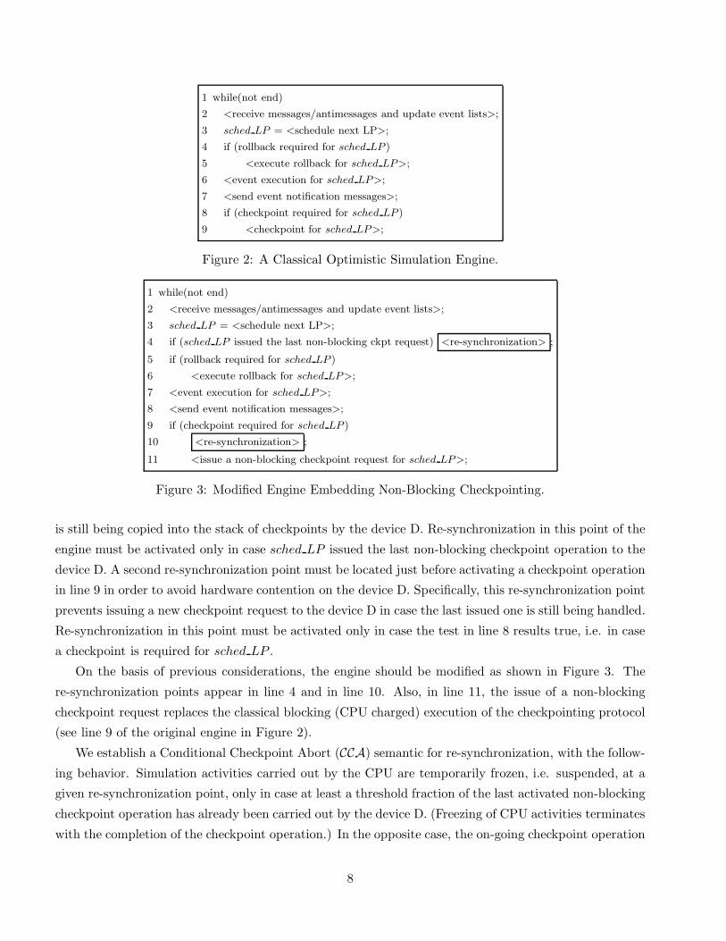
1 while(not end)
2 <receive messages/antimessages and update event lists>;
3 sched LP = <schedule next LP>;
4 if (rollback required for sched LP )
5 <execute rollback for sched LP>;
6 <event execution for sched LP>;
7 <send event notification messages>;
8 if (checkpoint required for sched LP )
9 <checkpoint for sched LP>;
Figure 2: A Classical Optimistic Simulation Engine.
1 while(not end)
2 <receive messages/antimessages and update event lists>;
3 sched LP = <schedule next LP>;
4 if (sched LP issued the last non-blocking ckpt request) <re-synchronization> ;
5 if (rollback required for sched LP )
6 <execute rollback for sched LP>;
7 <event execution for sched LP>;
8 <send event notification messages>;
9 if (checkpoint required for sched LP )
10 <re-synchronization> ;
11 <issue a non-blocking checkpoint request for sched LP>;
is still being copied into the stack of checkpoints by the device D. Re-synchronization in this point of the
engine must be activated only in case sched LP issued the last non-blocking checkpoint operation to the
device D. A second re-synchronization point must be located just before activating a checkpoint operation
in line 9 in order to avoid hardware contention on the device D. Specifically, this re-synchronization point
prevents issuing a new checkpoint request to the device D in case the last issued one is still being handled.
Re-synchronization in this point must be activated only in case the test in line 8 results true, i.e. in case
a checkpoint is required for sched LP .
On the basis of previous considerations, the engine should be modified as shown in Figure 3. The
re-synchronization points appear in line 4 and in line 10. Also, in line 11, the issue of a non-blocking
checkpoint request replaces the classical blocking (CPU charged) execution of the checkpointing protocol
(see line 9 of the original engine in Figure 2).
We establish a Conditional Checkpoint Abort (CCA) semantic for re-synchronization, with the follow-
ing behavior. Simulation activities carried out by the CPU are temporarily frozen, i.e. suspended, at a
given re-synchronization point, only in case at least a threshold fraction of the last activated non-blocking
checkpoint operation has already been carried out by the device D. (Freezing of CPU activities terminates
with the completion of the checkpoint operation.) In the opposite case, the on-going checkpoint operation
8
is aborted, with no freezing at all of CPU activities.
In the instance of checkpoint abort, data consistency is maintained since, in case sched LP is as-
sociated with a not yet completed non-blocking checkpoint operation, the operation itself is considered
as it had never been activated. Therefore, updates issued by sched LP on its state vector will never
ultimately result in a non-consistent checkpoint since the situation looks like no checkpoint at all was
ever scheduled for the state vector value prior to the updates. Analogously, no hardware contention ever
occurs since an on-going checkpoint operation is interrupted (i.e. taken away from the device D) before
any new checkpoint operation is activated.
On the other hand, in the instance of freezing of CPU activities, neither sched LP is allowed to update
its state vector while the vector itself is still being checkpointed, which maintains data consistency, nor it
can issue a non-blocking checkpoint request until the last issued one is completely handled by the device
D, which avoids hardware contention.
(Dynamically) controlling the threshold fraction value should allow the CCA re-synchronization se-
mantic to achieve good tradeoffs between the checkpointing cost experienced at the application level in
the form of freezing of CPU activities and the state recovery cost determined on the basis of the distance
between consecutive committed checkpoints at the same LP.
3.5 Remarks
As pointed out in Section 2.2, skipping a checkpoint after the execution of some simulation events by
completely avoiding to activate the checkpoint operation, is a classical solution for reducing the check-
pointing overhead in case of non-incremental methods based on blocking (CPU charged) execution of
the checkpointing protocol [4, 13, 25, 33, 35, 37]. We refer to this skipping approach as a-priori. On
the other hand, the notion of checkpoint abort underlying CCA actually introduces a kind of a-posteriori
checkpoint skipping, where “a-posteriori” means “after” the activation of the checkpoint operation itself.
This is orthogonal to, and thus combinable with, a-priori checkpoint skipping. As respect to this point,
the engine in Figure 3 exhibits a test in line 9 to verify whether a non-blocking checkpoint operation
must be activated for the lastly scheduled LP, namely sched LP . In the negative case, a-priori checkpoint
skipping is performed independently of the fact that the execution mode of the checkpointing protocol is
non-blocking. Insights on the effects of combining a-priori and a-posteriori checkpoint skipping will be
provided in the experimental analysis reported in Section 5.4.
As a last observation, we recall that classical a-priori skipping of checkpoints has the advantage of
keeping low the memory usage due to the reduced amount of recorded state information, which might
exhibit benefits when memory is a critical resource. Given the possibility to adopt a-priori skipping in
combination with the non-blocking execution mode of the checkpointing protocol, such an advantage can
be maintained while using non-blocking checkpointing. Overall, non-blocking checkpointing exhibits the
potential to reduce the cost of any single checkpoint operation while still allowing reduction of memory
usage whenever needed.
9
4 An Implementation for Myrinet Clusters
This section describes the implementation of a C library capable to support non-blocking checkpointing
on myrinet based clusters. This library exploits DMA capabilities proper of myrinet network hardware
to support data copy associated with checkpointing, therefore, in our perspective, the device D coincides
with a myrinet network card.
The library we present, which we will refer to as Checkpointing-and-Communication Library (CCL),
is an integrated software offering both checkpointing and low latency message delivery functionalities.
In this article our focus is on the presentation of checkpointing functionalities, however, given that
CCL is an extension of a classical message passing layer for myrinet, a short overview of how message
passing is implemented is mandatory for the comprehension of the extension. We will provide such an
overview in Section 4.2, just after the description of the specific myrinet hardware CCL has been designed
for. Then the extension to support non-blocking checkpointing is presented. As a last observation, we
remark that CCL has been developed for LINUX, kernel version 2.0.32, assuming an underlying hardware
architecture employing snooping-cache to maintain coherency between data in the cache memory and data
read/written from/to main memory [21].
4.1 Hardware
CCL has been designed for the M2M-PCI32C myrinet card (see Figure 4.a), based on the LANai 4 chip
[27], which is a programmable communication device consisting of:
(A) An internal bus, namely LBUS (Local BUS), clocked at twice the chip-clock speed.
(B) A programmable RISC processor connected to the LBUS, which we will refer to as LANai processor.
(C) A RAM bank of 1 Mbyte (LANai internal memory), connected to the LBUS, which is used for
storing both data and the driver run by the LANai processor, typically called control program. This
memory can be mapped into the memory address space of the host. Also, host access to the LANai
internal memory takes place through a PCI bridge.
(D) A packet interface between the myrinet switch and the LANai chip, accessible by the LANai pro-
cessor.
(E) Three DMA engines used respectively for: (i) packet-interface/internal-memory transfer operations
(Receive DMA), (ii) internal-memory/packet-interface transfer operations (Send DMA), and (iii)
internal-memory/host-memory (or vice-versa) transfer operations (EBUS DMA, namely External
Bus DMA). Internal-memory/host-memory transfer (or vice-versa) also takes place through the
PCI bridge.
The LANai processor cannot access host memory directly. Nonetheless, the control program run by
the LANai processor can set the EBUS DMA to perform data transfer to/from that memory.
10
Receive
DMA
EBUSDMA
EBUSDMA LANai Processor
LANai Chip
LBUS
Send
DMA InterfacePacket
1 MB RAM Bank
HOST
PCI Bridge
Receive queue (host memory)
(b)(a)
1 MB RAM Bank
LBUS
HOST
PCI Bridge
SB CS
sb stackj j
Figure 4: High Level Structure of the M2M-PCI32C Card (a) and Data Transfers Associated with Non-
Blocking Checkpointing (b).
4.2 Communication Functionalities
As in the common choice to fast speed messaging layers for myrinet (see for example [28]), in CCL
messages incoming from the network are temporarily buffered into the LANai internal memory (data
transfer between the packet interface and the internal memory takes place through the Receive DMA)
and then transferred into the receive queue, located onto host memory, through the EBUS DMA (see
the directed dashed line in Figure 4.a). Given that the message is already in the host memory when
performing a receive operation, this operation does not involve access to the PCI bridge, thus keeping at
a minimum the overhead of any message receipt.
The implementation of the receive queue in host memory needs reserved main memory pages for DMA
operations. Reservation of blocks of main memory pages takes place through the function get free pages()
internal to the kernel, activated through a kernel module that also notifies the main memory page ad-
dresses through the /proc file system. The function communication init() included in the API maps
the receive queue into the application address space through the mmap() system call on the /dev/mem
special device file.
A classical optimization called “block-DMA” is used to transfer incoming messages from the LANai
internal memory to the host memory. This optimization allows incoming messages stored in contiguous
message slots of the LANai internal memory to be transferred into the receive queue using a single EBUS
DMA operation.
Following another common design choice, any send operation issued by the application involves copy-
ing the message content directly into the LANai internal memory. This is also referred to as “zero-copy”
send. Then the message is transferred onto the network through the Send DMA. This optimization allows
11
keeping the delivery latency at a minimum by avoiding additional buffering in host memory at the sender
side.
The responsibility to program the three DMA engines anytime there is the need for a given data
transfer operation pertains to the control program run by the LANai processor, whose structure will be
presented in detail in Section 4.4. This program also handles an acknowledgment mechanism to support
reliability of message delivery.
The following API communication functions are available at the application level. (i) send msg(int
msg type, int machine id, void *msg), where msg type defines the type of the message, machine id
defines the destination host for the message, and msg is a pointer to the memory area containing the
data to be sent (7). This function passes to the network card the data to be transmitted by employ-
ing the zero-copy optimization previously described. (ii) receive msg(int msg type, void *msg, int
*machine id), which returns a message of a given type, if any, in the memory area pointed by msg, and
also the identifier of the sender host in the memory area pointed by machine id. Since the receive queue
is mapped into the application address space, this function copies the message content from the receive
queue into the buffer pointed by msg through a simple memcpy() call.
Message delivery latencies offered by CCL for specific message sizes are aligned with those offered by
other myrinet tailored message passing layers [28]. Information on delivery latency values for the specific
message size used in the experimental analysis presented in this paper will be provided in Section 5.1.
4.3 Checkpointing Functionalities
In CCL, a non-blocking checkpoint operation for LPj corresponds to a data copy from the state buffer
sbj to the stack of checkpoints stackj , which is performed by the EBUS DMA. As shown by the directed
dotted lines in Figure 4.b, the EBUS DMA uses the LANai internal memory as a temporary buffer.
Temporary buffering is needed since, as already mentioned, the EBUS DMA does not support host
memory to host memory data transfer directly. It only supports host memory to LANai internal memory
transfer or vice versa. Anyway, conventional computer architectures (e.g. IA-32 [20, 21, 22]) are typically
not equipped with hardware components, distinct from the CPU, able to perform host memory to host
memory data copy, thus making the intermediate buffering approach the only feasible solution for the
non-blocking checkpointing mode.
It would be possible to select other DMA engines, for example the video card DMA (AGP DMA) or
the south bridge DMA, to support non-blocking checkpointing. Our choice went to the EBUS DMA on
the myrinet card since operating system bypass mechanisms offered by the myrinet productor (Myricom
[26]) allow us to develop the most part of the CCL software as an application level library (8). The only
7In the current implementation the maximum amount of bytes that can be sent via a single message is determined at
compile time of CCL so that it can be tailored to requirements of any overlaying application.8Since the LANai internal memory can be mapped into application address space, the application level can interact with
the control program run by the LANai processor, i.e. the LANai driver, without passing through the operating system.
Software for mapping the LANai memory is provided by Myricom.
12
exception is the usage of the previously mentioned kernel module (see Section 4.2).
The usage of alternative DMA engines might also introduce additional problems. For instance, the
DMA of the south bridge, if any, would typically require a PCI device equipped with RAM storage, which
is mandatory for efficient intermediate buffering (9). With respect to the AGP DMA, it is relatively
unusual for video card vendors to provide technical specifications allowing one to rewrite the card driver
to support additional functionalities.
On the other hand, using the EBUS DMA forces data transfer associated with checkpointing to make
use of the PCI bus, which might give rise to slightly longer completion time for a checkpoint operation as
compared to what would be achieved using a DMA engine working on a bus faster than PCI, for instance
the AGP bus. In other words, the choice of the EBUS DMA represents a tradeoff between checkpointing
latency and simplicity of implementation.
Using the EBUS DMA on the myrinet card to perform non-blocking checkpointing matches the Device
Decoupling requirement identified in Section 3.2. Specifically, data transfer performed by the EBUS DMA
involves access to the host main memory while the CPU works into the cache memory. In other words,
there is no direct interference due to EBUS DMA data transfer on CPU activities. However, charging
the EBUS DMA with data transfer for checkpointing could produce a form of indirect interference due to
variations in the execution locality. Specifically, checkpoint stack entries are not referenced by the CPU
while taking the checkpoint, therefore they are not loaded into the cache while performing the checkpoint
operation. This might have both positive and negative effects. On the positive side, contention on cache
entries is reduced while taking the checkpoint. On the negative side, the checkpoint stack entry is not
available into the cache for future reference. However, even if CPU charged checkpointing has the effect
of loading any referenced checkpoint stack entry into the cache while taking the checkpoint, the involved
cache entries might get overwritten before a new reference to that checkpoint stack entry is made by the
simulation program. Therefore, CPU charged checkpointing might not favor locality anyway.
Also, a second form of indirect interference due to EBUS DMA data transfer associated with check-
pointing is related to the system bus traffic, caused by the two-way transfer of the state vector required
for the intermediate buffering into the LANai internal memory, which could theoretically increase the
latency of cache misses. However, as we will show in the experimental study in Section 5.3.3, non-blocking
checkpointing is effective even for simulation software exhibiting unusually low locality of references, case
in which the frequency of cache misses is expected to be non-minimal.
From the point of view of the simulation application, issuing a non-blocking checkpoint request con-
sists in notifying to the LANai processor that the EBUS DMA must be programmed for the data transfer
associated with checkpointing. This takes place through the API function non block ckpt(int LP id,
time type simulation clock), where LP id is the identifier of the LP whose state vector needs to be
checkpointed, and simulation clock is the value of the current simulation time of the LP (10). Actually,
9Intermediate buffering on secondary storage devices is infeasible since it would increase the latency of memory to memory
data copies to levels unacceptable in the optimistic simulation context.10time type is a redefinition of double.
13
CCL manages the checkpoint stacks of the LPs in a totally transparent way to the application program-
mer, which is the reason why LP id is a sufficient parameter to identify both the state buffer and the
entry into the stack of checkpoints that must be involved in the data copy (11). Mapping state buffers and
checkpoint stacks to LP identifiers is achieved through the initialization function checkpoint init(int
num LPs, int size) included in the API, that assigns to each LP both a state buffer (of up to size
bytes) and a checkpoint stack.
As for the receive queue, blocks of reserved main memory pages are used for both the state buffers of
the LPs and their stacks of checkpointed state vectors since the EBUS DMA needs host main memory ad-
dresses to perform read/write operations. The previously mentioned kernel module (see Section 4.2) also
reserves main memory pages for these blocks, which are then mapped into the simulation application ad-
dress space (again through mmap() on /dev/mem) by the checkpoint init() function. Each LP retrieves
the virtual address of the assigned state buffer through the function void *get state pointer(int
LP id) also included in the API.
Given that common kernel programming approaches assign a different main memory region to each
I/O device, no I/O device different from the myrinet card should access the memory pages reserved for
LP state buffers and checkpoint stacks. Therefore, the CPU is the only other device that might modify
the data being read/written by the EBUS DMA. As already explained in Section 3.4, this issue is tackled
through re-synchronization.
The execution of the non block ckpt() function has the effect to communicate to the control program
run by the LANai processor the physical addresses of the state buffer of the LP and of the entry into
the checkpoint stack. This is achieved by writing this information into a proper buffer located in the
LANai internal memory. Since the snooping cache protocol automatically maintains cache/main-memory
coherency, no explicit cache flushing must be performed upon issuing a non block ckpt() call for the
memory regions read/written by the EBUS DMA while performing checkpointing.
Transparent management of checkpoint stacks during a rollback phase is supported by the API func-
tion reload ckpt(int LP id, time type recovery time), which reloads into the state buffer associ-
ated with LP id the earliest checkpoint whose simulation time is less than or equal to recovery time.
Invocation of this function has also the effect of transparently pruning the stack by all the checkpoints,
if any, with simulation time larger than recovery time.
The API includes also the function prune ckpt stack(int LP id, time type global virtual time),
which allows transparent storage recovery of busy entries of the checkpoint stack associated with LP id
during a fossil collection phase. Execution of this function has the effect to prune the checkpoint stack
associated with LP id by all the checkpoints, except the earliest one, with simulation time less than or
equal to global virtual time.
11LP identifiers must range between 0 and n− 1, where n is the number of LPs hosted by the machine. Mapping into this
range is required if a different identification is used at the simulation application level.
14
1. While (1)
2. if (message needs to be sent) <activate Send DMA>;
3. if (message needs to be received) <activate Receive DMA>;
4. if (EBUS DMA not busy)
5. if (block-DMA not needed AND checkpoint burst needed) ckpt burst();
6. if (block-DMA needed AND checkpoint burst not active) <activate block-DMA>;
Figure 5: Structure of the Control Program.
4.4 Structure of the Control Program
The control program run by the LANai processor has the responsibility to activate and control the
three DMA engines on board of the card. This program must be structured in a way to ensure the
Non-Intrusiveness requirement identified in Section 3.2. In this context, Non-Intrusiveness means that
communication functionalities must not suffer from the activation of checkpointing functionalities. To
achieve this, we have structured the control program as shown in Figure 5. Specifically, any checkpoint
operation is split by the control program into a sequence of invocations of the function ckpt burst().
Each invocation has the effect to program the EBUS DMA to transfer up to a maximum amount of bytes,
called burst, from the LP state vector to the LANai internal memory (intermediate buffering) or from
the LANai internal memory to the checkpoint stack of the LP.
Actually, splitting the checkpoint operation into a sequence of bursts avoids keeping the hardware on
board of the myrinet card (i.e. the EBUS DMA, the PCI bridge and the LBUS) busy due to checkpointing
for excessively long periods (12). This feature, together with the lower priority assigned to data transfer
associated with checkpointing as compared to block-DMA (13), actually permits to respect the Non-
Intrusiveness requirement. In [34] we have shown how to identify the maximum value for the burst
length, which allows the performance of communication functionalities not to be significantly perturbed
by the activation of checkpointing functionalities.
4.5 Implementation of Re-Synchronization
The CCA semantic for re-synchronization relies on the ability to track the advancement status of an on-
going non-blocking checkpoint operation in order to determine whether to commit or abort the operation
itself. Given that, due to the Non-Intrusiveness requirement, any checkpoint operation is split by the
12Access to the EBUS DMA, the PCI bridge and the LBUS is required for block-DMA operations, which transfer messages
incoming from the network into the receive queue. Also, access to the PCI bridge and the LBUS is required for zero-copy
sends issued by the application.13EBUS DMA data transfer operations associated with checkpointing functionalities are activated only in case no block-
DMA operation is currently required to transfer messages into the receive queue located onto host memory (see line 5 of the
control program), thus achieving lower priority of data transfer associated with checkpointing as compared to block-DMA.
We have not used preemption on data transfer associated with checkpointing to favor communication since, according to
hardware specifications [27], we might incur problems with the PCI protocol.
15
control program run by the LANai processor into a sequence of EBUS DMA data transfer operations,
namely bursts, a straightforward way to track the advancement of any on-going checkpoint operation
consists in counting the number of already completed EBUS DMA data transfers (from/to host memory)
associated with that operation. To implement this solution we have introduced a counter in the LANai
internal memory, namely completed transfers, which is managed as follows. The counter is reset by the
function non block ckpt() upon issuing a checkpoint request at the application level. It is incremented
by the control program each time the program becomes aware that an EBUS DMA data transfer (from/to
host memory) associated with the checkpoint operation has been completed.
The API includes the re-synchronization function ckpt cond abort(float threshold). The pa-
rameter threshold indicates the completion percentage (i.e. the threshold fraction) of the last activated
checkpoint operation, if any, under which the checkpoint operation must be aborted according to the CCA
semantic. To decide whether to abort the checkpoint operation or not, ckpt cond abort() needs infor-
mation about both the current value of the completed transfers counter and the total number of EBUS
DMA data transfers required for the operation. We maintain the latter information into an additional
variable located onto host memory, namely total transfers, visible to the function ckpt cond abort(),
as well as to the function non block ckpt().
As soon as the checkpoint operation is issued by the application, the function non block ckpt()
computes the total number of EBUS DMA transfers (from/to host memory) to complete the operation
according to the following expression:
total transfers = 2 × ⌈state vector size
burst length⌉ (1)
where the multiplier factor 2 takes into account the fact that data transfer for checkpointing needs inter-
mediate buffering. The variable total transfers stores the obtained result, making it available to the
function ckpt cond abort(). The function ckpt cond abort() takes the decision on whether to abort or
not the last activated checkpoint operation on the basis of the condition completed transfers
total transfers< threshold.
The operation is aborted in case the condition is verified.
Notification of the checkpoint abort decision to the control program run by the LANai processor
takes place through a flag, namely ckpt abort, implemented as a word located into the LANai internal
memory (14), which is managed as follows. The flag is initialized to zero. It is set to one by the function
ckpt cond abort() in case the checkpoint abort decision is taken. It is eventually reset by the control
program after it has interrupted EBUS DMA data transfer associated with checkpointing.
Abort of an on-going checkpoint operation cannot take place as a preemption of an in-progress EBUS
DMA data transfer since, as already pointed out, hardware specifications [27] indicate that preemption
may cause problems to the PCI protocol. Therefore, interruption is implemented by simply avoiding the
14We have used a word instead of a single byte for the flag ckpt abort since the LANai 4 chip internal circuitry is optimized
for aligned words access. Also, the host CPU accesses an aligned word using a single bus cycle, as it would be for the case
of a single byte.
16
activation of additional EBUS DMA transfers related to that checkpoint operation.
As a last point, if the checkpoint abort condition (i.e. completed transfers
total transfers< threshold) is not veri-
fied, the function ckpt cond abort() behaves as follows. It returns immediately in case the checkpoint
operation has already been completed. Otherwise it spin-locks around a flag ckpt completed, also im-
plemented as a word located in the LANai internal memory, which is managed as follows. It is set to zero
by the function non block ckpt(), upon issuing a checkpoint request. It is eventually set to one by the
control program run by the LANai processor as soon as the data transfer associated with the checkpoint
request has been completed.
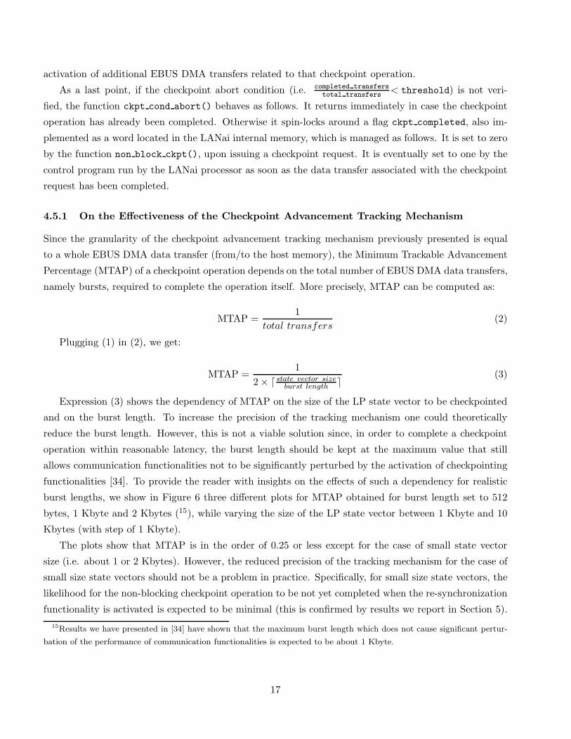
4.5.1 On the Effectiveness of the Checkpoint Advancement Tracking Mechanism
Since the granularity of the checkpoint advancement tracking mechanism previously presented is equal
to a whole EBUS DMA data transfer (from/to the host memory), the Minimum Trackable Advancement
Percentage (MTAP) of a checkpoint operation depends on the total number of EBUS DMA data transfers,
namely bursts, required to complete the operation itself. More precisely, MTAP can be computed as:
MTAP =1
total transfers(2)
Plugging (1) in (2), we get:
MTAP =1
2 × ⌈state vector sizeburst length
⌉(3)
Expression (3) shows the dependency of MTAP on the size of the LP state vector to be checkpointed
and on the burst length. To increase the precision of the tracking mechanism one could theoretically
reduce the burst length. However, this is not a viable solution since, in order to complete a checkpoint
operation within reasonable latency, the burst length should be kept at the maximum value that still
allows communication functionalities not to be significantly perturbed by the activation of checkpointing
functionalities [34]. To provide the reader with insights on the effects of such a dependency for realistic
burst lengths, we show in Figure 6 three different plots for MTAP obtained for burst length set to 512
bytes, 1 Kbyte and 2 Kbytes (15), while varying the size of the LP state vector between 1 Kbyte and 10
Kbytes (with step of 1 Kbyte).
The plots show that MTAP is in the order of 0.25 or less except for the case of small state vector
size (i.e. about 1 or 2 Kbytes). However, the reduced precision of the tracking mechanism for the case of
small size state vectors should not be a problem in practice. Specifically, for small size state vectors, the
likelihood for the non-blocking checkpoint operation to be not yet completed when the re-synchronization
functionality is activated is expected to be minimal (this is confirmed by results we report in Section 5).
15Results we have presented in [34] have shown that the maximum burst length which does not cause significant pertur-
bation of the performance of communication functionalities is expected to be about 1 Kbyte.
Figure 6: MTAP vs the LP State Vector Size for Different Values of the Burst Length.
Therefore, for small state vector size the CCA re-synchronization semantic is actually insensitive to the
precision of the tracking mechanism, thus allowing the mechanism not to exhibit real ineffectiveness.
5 Experimental Analysis with the PHOLD Benchmark
In this section we report an experimental analysis of non-blocking checkpointing conducted using the
PHOLD synthetic benchmark. This study aims at observing the behavior of the non-blocking mode while
varying simulation application settings. The PHOLD benchmark, originally presented in [16], consists of
a fixed number of LPs and of a constant number of messages (jobs) circulating among the LPs, which is
referred to as message population. A message simply triggers the production of a new message with an
increased timestamp value. Both the routing of messages among the LPs and the timestamp increments
are taken from some stochastic distributions. Although a set of standard benchmarks for parallel discrete-
event simulation does not exist, PHOLD is in practice one of the most used ones [1, 2, 33, 35, 38, 43].
Before entering the analysis, we report a description of the testing environment we have used and of the
testing methodology employed.
5.1 Testing Environment
The experiments were all performed on a cluster of Pentium II 300 MHz (128 Mbytes RAM - 512 Kbytes
second level cache). All the PCs of the cluster run LINUX (kernel version 2.0.32) and are equipped with
M2M-PCI32C myrinet cards. On the basis of the methodology we have presented in [34], burst length of
1 Kbyte has been selected for this cluster environment.
The simulation software implements the events as a compound structure with several fields (sender,
receiver, timestamp etc.). For the case of PHOLD, this structure has total size 36 bytes and using CCL
any message carrying an event is delivered to the recipient within about 20/25 microseconds when no
congestion occurs on the switch. The same delay characterizes the transmission of antimessages. Message
exchange among LPs hosted by the same machine does not involve operations of the CCL layer. There is
an instance of the optimistic simulation engine on each machine. The engine manages the local event list
18
(consisting in the logical collection of the event lists of the local LPs) and schedules LPs for event execution
according to the Smallest-Timestamp-First algorithm [24]. The LPs are implemented as application level
threads. Memory space for new entries into the event lists of the LPs is allocated dynamically using
classical malloc() calls. Therefore there is no pool of pre-allocated buffers. Antimessages are sent
according to the aggressive policy [18], i.e. they are sent as soon as an LP rolls back. Fossil collection is
executed periodically.
5.2 Testing Methodology
As we have seen in Section 3.5, the CCA semantic for re-synchronization determines a particular type of
checkpointing strategy based on a-posteriori skipping of checkpoints. As respect to this point, we have
decided to split the analysis with the PHOLD benchmark in two parts.
In the first one, namely Part A, we study the effects of this strategy with no interference between
a-posteriori and a-priori checkpoint skipping. Specifically, the results for non-blocking checkpointing
reported in Part A have been obtained by imposing always positive result to the test in line 9 of the
simulation engine in Figure 3, so that a non-blocking checkpoint operation is requested after the exe-
cution of each simulation event (i.e. no a-priori checkpoint skipping is ever performed). In this part
of the study we have initially treated threshold (i.e. the argument to the re-synchronization function
ckpt cond abort()), as the independent parameter. Therefore, we have tested the behavior of non-
blocking checkpointing assuming a set of different values for threshold, manually moving it from one
value to another while performing the experiments. Then we have also addressed the issue of run-time
adaptive tuning of this parameter.
The second part of the study, namely Part B, is instead devoted to the observation of the effects of
combining both a-posteriori and a-priori checkpoint skipping.
Basically, we report measures related to the event rate, that is the number of committed events per
time unit, which is representative of the simulation execution speed, and also to the following parameters:
• The frequencies F1 and F2 of checkpoint abort upon the invocation of the re-synchronization func-
tion. F1 relates to re-synchronization in line 4 of the optimistic simulation engine in Figure 3, while
F2 relates to re-synchronization line 10.
• The average distance (number of events) between two consecutive committed checkpoints of the
same LP. This parameter allows us to measure the “density of committed checkpoints” (as respect
to the amount of executed events) at the point where the event rate, namely the performance, is
maximized.
Additional metrics will be introduced, whenever required, in some parts of the analysis.
We test non-blocking checkpointing against a classical Periodic State Saving (PSS) strategy based on
19
CPU charged (blocking) checkpointing (see Section 2.2) (16). For this strategy, we report both the peak
event rate and the corresponding value of the checkpoint interval χ. In our experiments, CPU charged
checkpointing is implemented efficiently as a memcpy() call that copies the state vector of the LP into
the stack of checkpointed states of that LP. As CCL adopts reserved main memory pages for both the
LP state vectors and their checkpoint stacks, to ensure fairness in the comparison we have used the same
approach for the case of CPU charged checkpointing.
Mean value analysis is employed, and each reported parameter value results as the average over 10
runs, all done with different random seeds. At least 2 × 10⁶ committed events were simulated in each
run.
5.3 Part A
5.3.1 Basic Test Case
As a basic test case we have considered a PHOLD benchmark with 32 LPs evenly distributed on 4
machines of the previously described cluster. The message population has been fixed at 1 message per
LP and messages are equally likely to be forwarded to any LP, with timestamp increments following an
exponential distribution with mean 10 simulation time units.
In the experiments we have fixed the event execution time at about 150 microseconds, obtained
by structuring the event routine as a simple CPU busy loop [30, 38], which has been selected as an
intermediate event granularity value for parallel discrete event simulation applications (17). As respect
to the LP state vector size, we have varied it between 100 bytes and 8 Kbytes (passing through 2 and 4
Kbytes), so as to cover a relatively large range of values for the state granularity. The results are reported
in Figure 7.
The plots for the event rate show that non-blocking checkpointing provides execution speed improve-
ments over PSS (up to 13% for 8 Kbytes state vector size) except for the case of minimal state granularity,
i.e. 100 bytes state vector. Such a result is an expected one since minimal state granularity implies neg-
ligible overhead in case of CPU charged checkpointing, which can be comparable with the overhead to
manage non-blocking checkpointing (e.g. the overhead due to the activation of non-blocking checkpoint
operations, which involves data exchange between host and LANai memory through the PCI bridge).
We have noted no relevant difference in the execution efficiency, evaluated as the ratio between the
amount of committed events and the total number of executed events (committed plus rolled back), be-
tween non-blocking checkpointing and PSS. Therefore the performance gain of non-blocking checkpointing
16For some particular simulation problems with regular patterns for the difference between timestamps of successive events,
performance improvements over PSS can be achieved by relaxing the constraints that CPU charged checkpoints must be
taken on a periodic basis [33]. However, PSS remains, in general, a performance effective strategy.17For simulation applications with very coarse event granularity, the CPU overhead due to checkpointing tends to become
a minor issue, thus reducing the impact of optimizations like non-blocking checkpointing. This is the reason why we have
considered an intermediate event granularity value in this part of the study. Anyhow, we shall consider later finer event
granularity when running simulations of the PCS model.
20
0.0 0.2 0.4 0.6 0.8 1.0threshold
11000
12000
13000
14000
15000ev
ent r
ate
100 bytes state vector2 Kbytes state vector4 Kbytes state vector8 Kbytes state vector
0.0 0.2 0.4 0.6 0.8 1.0threshold
1.00
1.10
1.20
1.30
1.40
aver
age
dist
ance
bet
wee
n co
mm
itted
che
ckpo
ints
100 bytes state vector2 Kbytes state vector4 Kbytes state vector 8 Kbytes state vector
0.0 0.2 0.4 0.6 0.8 1.0threshold
0.00
0.05
0.10
0.15
0.20
F1
100 bytes state vector2 Kbytes state vector4 Kbytes state vector8 Kbytes state vector
0.0 0.2 0.4 0.6 0.8 1.0threshold
0.00
0.05
0.10
0.15
0.20
F2
100 bytes state vector2 Kbytes state vector4 Kbytes state vector8 Kbytes state vector
PSS
State Vector Size Best χ Peak Event Rate
100 Bytes 1 14752
2 Kbyte 2 13736
4 Kbytes 3 12474
8 Kbytes 3 11426
Figure 7: Results for the Basic Test Case.
does not derive from reductions of the amount of rollback, i.e. from indirect effects due to changes in the
execution mode of the checkpointing protocol. The efficiency values for this experiment are in the order
of 85%, with rollback frequency and rollback distance in the order of 12% and 1.25 events, respectively.
Another interesting point is that plots for the event rate assume different shapes depending on the
size of the state vector. In particular, plots for 100 bytes and 2 Kbytes state vector size are almost flat.
Instead, those for 4 Kbytes and 8 Kbytes state vector size exhibit a clear dependency on threshold.
Specifically, for 4 Kbytes state vector size the event rate increases from about 12700 to 13300 committed
events per sec. while moving threshold from 0.0 to 0.6, and then stabilizes. For 8 Kbytes state vector
size, the event rate starts from about 11700 committed events per sec. when threshold is set to 0.0, and
then reaches a peak of about 12900 committed events per sec. when threshold is set to 0.4. Notice that
after reaching the maximum value, the curve of the event rate does not stay flat as for the case of 4 Kbytes
state vector size. By these results the low sensitivity of the execution speed vs threshold for the case of
relatively small state vectors is an empirical support to the effectiveness of the tracking mechanism for the
checkpoint operation advancement described in Section 4.5. As already said, the mechanism exhibits finer
granularity for medium/large state vectors, case in which the selection of threshold, and thus adequate
management of the CCA re-synchronization semantic, is a critical factor for the final performance.
From the values of F1 and F2 reported in Figure 7 we note that, with the exception of 8 Kbytes state
21
vector size, almost all the checkpoint aborts are due to re-synchronization in line 4 of the simulation
engine in Figure 3, i.e. re-synchronization preventing the checkpoint inconsistency problem. We recall
that re-synchronization in line 4 is activated only in case sched LP issued the last non-blocking checkpoint
request. Therefore, uncommitted checkpoints are mainly due to locality of event occurrences at the same
LP over a period of simulation time. Instead, for the case of 8 Kbytes state vector size and threshold
set to 1.0, some checkpoint aborts are due to the fact that sometimes, but not frequently, CCL is unable
to complete the last activated non-blocking checkpoint request before a new request is issued. Given the
largeness of the state vector, this was an expected behavior. Anyway F2 remains null, or almost null, for
values of threshold up to 0.8, therefore we have a clear indication that, in spite of the largeness of the
state vector, almost all the work associated with data copy due to checkpointing was actually completed
before the activation of a new checkpoint request.
An interesting observation is related to the particular shape of the curve for the average distance
between committed checkpoints in case of 8 Kbytes state vector size. In particular, this curve shows two
different steps, one for threshold set to 0.2, the other one for threshold set to 1.0. However, only the
first step produces an increase in the event rate due to a decrease in the checkpointing overhead (i.e. the
overhead due to freezing of CPU activities). The reason for this is as follows. The plot related to F1 shows
that when threshold is moved from 0.0 to at least 0.2, we get a non-minimal amount of checkpoint aborts
due to re-synchronization in line 4. This allows aborting most of the checkpoint operations associated
with calls to non block ckpt() in line 11 of the simulation engine in case the calling LP is re-scheduled
for execution, which produces a strong reduction of the checkpointing overhead since committing those
checkpoints would be costly, in terms of freezing of CPU activities, due to their recent activation. At the
same time, the second step in the average distance between checkpoints is exclusively due to the increase
in the frequency F2 when threshold is moved from 0.8 to 1.0, which, unlike the previous case, does not
produce relevant decrease in the checkpointing overhead since the additional aborts involve checkpoints
with short expected completion latency due to their non-recent activation. Combining this with the
monotonic increase of coasting forward cost vs threshold (due to the increase in the average distance
between committed checkpoints) we get the slight decrease in the event rate noted after the peak in 0.4.
5.3.2 Effects of Increased Workload
In this section we consider a PHOLD configuration similar to the one in Section 5.3.1, but with message
population increased to 10 messages per LP. As compared to 1 message per LP, this increased workload
actually produces an execution with longer rollback distance (in the order of 2.5 events) occurring with
reduced frequency (in the order of 3%). In other words, this configuration allows us to test the effects
of variations of the rollback pattern. Note that longer rollback distance means that longer antimessage
communication bursts occur during a rollback phase. Therefore this configuration provides indications
for communication traffic exhibiting different characteristics. Also in this case we have used 4 machines,
with even distribution of the 32 LPs on the machines.
22
0.0 0.2 0.4 0.6 0.8 1.0threshold
13000
14000
15000
16000ev
ent r
ate
100 bytes state vector2 Kbytes state vector4 Kbytes state vector8 Kbytes state vector
0.0 0.2 0.4 0.6 0.8 1.0threshold
1.00
1.10
1.20
1.30
1.40
aver
age
dist
ance
bet
wee
n co
mm
itted
che
ckpo
ints
100 bytes state vector2 Kbytes state vector4 Kbytes state vector8 Kbytes state vector
0.0 0.2 0.4 0.6 0.8 1.0threshold
0.00
0.05
0.10
0.15
0.20
F1
100 bytes state vector2 Kbytes state vector4 Kbytes state vector8 Kbytes state vector
0.0 0.2 0.4 0.6 0.8 1.0threshold
0.00
0.05
0.10
0.15
0.20
F2
100 bytes state vector2 Kbytes state vector4 Kbytes state vector8 Kbytes state vector
PSS
State Vector Size Best χ Peak Event Rate
100 Bytes 1 16133
2 Kbytes 4 15903
4 Kbytes 8 15318
8 Kbytes 10 14631
Figure 8: Results for Increased Workload.
The results are reported in Figure 8. They are mostly aligned with those obtained in case of the 1
message per LP workload. There are however some differences. For minimal (100 bytes) state vector
size, PSS exhibits a slightly higher gain over non-blocking checkpointing. Also, the performance gain
of non-blocking checkpointing for medium/large state vector size is slightly reduced. This is due to the
fact that with a reduced rollback frequency, PSS achieves the best performance for a larger value of the
checkpoint interval χ, thus allowing a stronger reduction of the CPU overhead due to checkpointing.
As a last observation, differently from the 1 message per LP case, the plot for the event rate stays
flat after reaching the maximum value for threshold set to 0.4. This is because the increase in the state
recovery cost, due to the increase in the average distance between committed checkpoints while moving
threshold from 0.4 to 1.0 (which produces longer coasting forward), has negligible impact since rollbacks
are less frequent.
5.3.3 Effects of Increased System Bus Traffic
The benchmark configurations used in Section 5.3.1 and in Section 5.3.2 are both characterized by event
routine implemented as a simple busy loop. In this situation, event execution does not involve main
memory access, which does not reduce the system bus bandwidth available for data transfer operations
23
0.0 0.2 0.4 0.6 0.8 1.0threshold
10000
11000
12000
13000ev
ent r
ate
100 bytes state vector2 Kbytes state vector4 Kbytes state vector8 Kbytes state vector
0.0 0.2 0.4 0.6 0.8 1.0threshold
1.00
1.10
1.20
1.30
1.40
aver
age
dist
ance
bet
wee
n co
mm
itted
che
ckpo
ints
100 bytes state vector2 Kbytes state vector4 Kbytes state vector8 Kbytes state vector
0.0 0.2 0.4 0.6 0.8 1.0threshold
0.00
0.05
0.10
0.15
0.20
F1
100 bytes state vector2 Kbytes state vector4 Kbytes state vector8 Kbytes state vector
0.0 0.2 0.4 0.6 0.8 1.0threshold
0.00
0.02
0.04
0.06
F2
100 bytes state vector2 Kbytes state vector4 Kbytes state vector8 Kbytes state vector
PSS
State Vector Size Best χ Peak Event Rate
100 Bytes 1 12659
2 Kbytes 1 11836
4 Kbytes 2 10947
8 Kbytes 3 10061
Figure 9: Results for Increased System Bus Traffic.
associated with non-blocking checkpointing. To study a different situation in which event execution com-
petes with non-blocking checkpointing for system bus bandwidth, we have considered the same benchmark
as the one in Section 5.3.1, with a modified structure of the event routine code. Specifically, we have
structured the event routine as a loop that performs memset() calls circularly issued on contiguous sets
of entries of the state vector of the LP. This originates RAM accesses for (i) memory updating due to
write back from the cache each time contention on a cache slot occurs and (ii) cache updating upon
write misses. Note that this configuration is actually an unfavorable test case since event execution code
exhibits unrealistically low locality due to the fact that a state vector entry is referenced only after all the
other entries have been referenced by the event routine software. We set the length of the loop performing
memset() in order to obtain loop completion within about 150 microseconds when there is no other active
user load. As for previous test cases, we have used 4 machines, with even distribution of the LPs on the
machines.
The results, reported in Figure 9, confirm the tendencies noted for the case of the experiment in
Section 5.3.1. In particular, the gain due to non-blocking checkpointing in case of non-minimal state
vector size is confirmed also with this setting. For 8 Kbytes state vector size, this gain is in the order of
12% when threshold is set to 0.6. For 4 Kbytes state vector size, it is in the order of 9%, also in this
case when threshold is set to 0.6.
24
0.0 0.2 0.4 0.6 0.8 1.0threshold
0
2
4
6
8
10
12
14
max
imum
dis
tanc
e be
twee
n co
mm
itted
che
ckpo
ints
100 bytes state vector2 Kbytes state vector4 Kbytes state vector8 Kbytes state vector
1 message per LP
0.0 0.2 0.4 0.6 0.8 1.0threshold
0
5
10
15
20
max
imum
dis
tanc
e be
twee
n co
mm
itted
che
ckpo
ints
100 bytes state vector2 Kbytes state vector4 Kbytes state vector8 Kbytes state vector
10 messages per LP
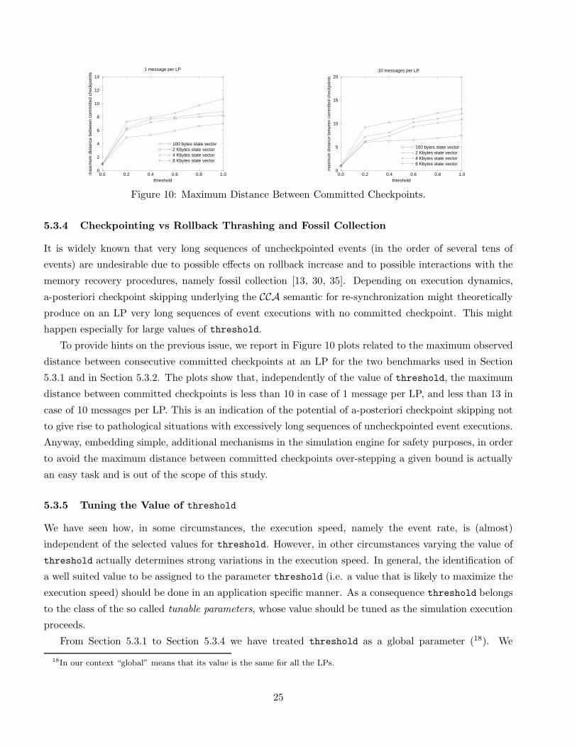
Figure 10: Maximum Distance Between Committed Checkpoints.
5.3.4 Checkpointing vs Rollback Thrashing and Fossil Collection
It is widely known that very long sequences of uncheckpointed events (in the order of several tens of
events) are undesirable due to possible effects on rollback increase and to possible interactions with the


![Hypervisor-Assisted Application Checkpointing in ...osinside.net/mlee/dsn2011_minlee.pdfcheckpointing of virtual machines using a special-purpose checkpointing VM. Remus [19] and Kemari](https://static.documents.pub/doc/80x56/5ed9f58028db2d5ca249272a/hypervisor-assisted-application-checkpointing-in-checkpointing-of-virtual-machines.jpg)


