Page 1
7th
International Symposium on NDT in Aerospace – Mo.5.A.7
1 License: http://creativecommons.org/licenses/by/3.0/
NON-DESTRUCTIVE EVALUATION OF AIRCRAFT
CABLES USING ULTRASONIC GUIDED WAVE
TECHNIQUE
Alvin Yung Boon CHONG 1
, Shu-Mei TAN 1
, Raj ARONDEKAR 1
,
Thayaparan PARTHIPAN 2
, Paul JACKSON 2, Serafeim MOUSTAKIDIS
3,
Vassilios KAPPATOS 1
, Cem SELCUK 1
, Tat-Hean GAN 1
1 Brunel Innovation Centre, Brunel University London, Granta Park, Great Abington,
Cambridge, CB21 6AL United Kingdom
Phone: +44 (0)1223 899512, Fax: +44 (0)1895 232806, e-mail: [email protected] ,
[email protected] 2
Plant Integrity Ltd, Granta Park, Great Abington, Cambridge, CB21 6AL United
Kingdom. e-mail: [email protected] 3
Centre for Research & Technology Hellas, Athens, Greece. e-mail:
[email protected]
Abstract
The degradation of aircraft wire structure over time due to environmental and operational
conditions can potentially become a source of electrical unreliability. This consequently
compromise the functionality of instruments and safety of the aircraft. Therefore, it is
essential to develop an inspection technique to accurately determine the health of electrical
wiring, in particular to inspect the condition of the insulation during maintenance
efficiently. Recently, the use of Ultrasonic Guided Wave (UGW) has gained wide attention
in the field of Non-Destructive Testing (NDT) notably in the application for pipeline
inspection. In this paper, a mobile UGW system is developed by utilizing transducer based
on Macro Fibre Composite (MFC). Numerical studies using Finite-Element Method (FEM)
have been used to study the frequency and transient characteristics on the modes of wave
propagation in wire structures. Representative aircraft cables with well classified insulation
defects were subjected to the UGW inspection system operating at frequencies range of 10
– 20 kHz. The data acquired by the pulser/receiver unit was further processed with a Hybrid
Defect Detection (HDD) algorithm in order to automate the result analysis. The results
yield a standard deviation of 0.25 m which provides an indication on the applicability of the
proposed system to inspect small insulation defects for a length of 6 m cable bundle.
Page 2
Project overview
• Feasibility study for novel wiring inspection technique based on the use of
Ultrasonic Guided Wave (UGW).
• Wires act as wave guides.
• Insulation damage will be characterized by defect detection algorithm.
Problems in aircraft wiring
Proposed solution.
• Aging of wires (due to environmental &
operation conditions).
• Arcing.
• Difficult to access certain part of the wire
(i.e. not exposed).
• Massive cable looms.
(Ref: McDanels SJ, Space Shuttle Columbia
Aging Wiring Failure Analysis, NASA report)
Copyright© Brunel Innovation Centre
Typical inspection of wiring
Method: Visual inspection (Ref: http://www.af.mil/News/Photos.aspx?igphoto=2000577959)
Method: Pulse Arrested Spark Discharge(Ref: Astronics test system)
Method: Optical Time Domain Reflectometry (Ref: KITCO System)
Method: Infrared thermography(Ref: Infrared imaging services LLC)
Method: Frequency Domain
Reflectometry (FDR)
(Ref: MOHR System)
• Prone to error
• Need full access of wire
• Accidentally causing damage
• Prone to error
• Need full access of wire
• Accidentally causing damage
• Only to test metallic core• Only to test metallic core
• Suitable only for fibre
optic cable
• Suitable only for fibre
optic cable
• Need full access of wire
• Complexity increases due to
scalability
• Complex data
interpretation
Copyright© Brunel Innovation Centre
2
Page 3
Introduction on Ultrasonic Guided Wave (UGW)
(Ref: https://en.wikipedia.org/wiki/Guided_wave_testing)
• Also known as Long Range
Ultrasonic Test (LRUT)
• Typical operating frequencies
around 10 – 100 kHz
• Also known as Long Range
Ultrasonic Test (LRUT)
• Typical operating frequencies
around 10 – 100 kHz
• An example of ultrasonic
guided wave testing
performed on a pipe using
Teletest System.
(Ref: https://www.flickr.com/photos/twiltd/14547059419 )
Copyright© Brunel Innovation Centre
• COMSOL® Multiphysics was used to validate the work
performed in disperse® and model complex geometry (i.e.
insulation/multiple cores).
• COMSOL® is an FEM based software which subdivides a
complex geometry domain into several elements, and
provides approximate solutions to Partial Differential
Equations. (PDE).
Numerical modelling software: Finite
Element Method (FEM)
Copyright© Brunel Innovation Centre
3
Page 4
Cont. FEM• Eigenfrequency analysis** used to determine natural
frequencies and mode shapes using COMSOL.
�. −���� − �� + . �� + �� = �� ������ − �� ���� ���
Governing equation:
• Eigenfrequencies (�� ���) in the structural mechanics field is
related to the eigenvalue (�� ���) returned by the solver
through:
�� ��� =����(�� ���)
2�
• Input parameters for the material properties that are
necessary for COMSOL model;
- Density , Poisson’s ratio & Young’s Modulus
**S. Soua, A. Raude, and T-H. Gan, “Guided Wave in Engineering Structures Using Non-Contact
Electromagnetic Acoustic Transducers – A Numerical Approach for the Technique Optimisation.” (2009)
Copyright© Brunel Innovation Centre
Cont: Modelling Benchmark (FEM)
3kg/m 1700
0.35
GPa 110E
=
=
=
ρ
ν
Fixed constrained on the edge boundaries
Copyright© Brunel Innovation Centre
1m
(Picture illustration of the copper rod)
Wire diameter: 2.4 mm
• Tetrahedral mesh.
• No. of elements: At least 10 elements per
wavelength (max. element size = 8 x 10-12).
• Freq sweep: 10 kHz to 200 KHz.
4
Page 5
Cont: Results for the modelling Benchmark (FEM)
Longitudinal mode @
21341 Hz
Torsional mode @
23089 Hz
Flexural mode @ 21054 Hz
n
L =λ
λf=c
L = length of rod (i.e. 1 m)n = standing wave count
c = wave velocity= Eigenfrequencyf
Post processing of COMSOL® results to
obtain dispersion curve.
0.02 0.04 0.06 0.08 0.1 0.12 0.14 0.16 0.18 0.20
0.5
1
1.5
2
2.5
3
3.5
4
4.5
Frequency [MHz]
Vp
h [km
/s]
Error analysis Benchmark model
Comsol
disperse
L(0,1)
T(0,1)
F(1,1)
Copyright© Brunel Innovation Centre
Dispersion curve data between COMSOL® and Disperse®
agree well for our application!
Transient analysis (FEM)0.1 ms
0.3 ms
0.6 ms
0 0.5 1 1.5 2 2.5 3 3.5
x 10-4
-1
-0.8
-0.6
-0.4
-0.2
0
0.2
0.4
0.6
0.8
1
Source: 16 kHz, 5 cycle sine hanning window.
Simulation time: 0 – 0.6 ms (steps: 6µs)
Time to compute: ≅ 45 mins.
1mm2 Defect
simulation Copyright© Brunel Innovation Centre
5
Page 6
Transducer holder design (prototype)
• Adjustable compression
• Non-conductive material (around
transducers).
MFC (type - P1)
Copyright© Brunel Innovation Centre
Ref: http://www.smart-material.com/MFC-
product-main.html
Hardware
Copyright© Brunel Innovation Centre
Developed by project collaborator (Plant Integrity Ltd)
Ref: T. Parthipan, P. Jackson, A. Chong, M. Legg, V. Kappatos, A. Mohimi, C. Selcuk, T.H. Gan, S.
Moustakidis and K. Hrissagis, “Long Range Ultrasonic Inspection of Aircraft Wiring – Technique and
hardware development” (2014).
6
Page 7
Safewire system testing on bundle of cable
Copyright© Brunel Innovation Centre
Experiment setup
Cont. Safewire system testing on bundle of cable
Copyright© Brunel Innovation Centre
Cross section of cable
(55D0211-10-9, AWG size 10)
End of 6 m
cable loom
Transmitting
and receiving
transducers
Material of cable illustrated
using , 55D0211-22-9, AWG
size 22)
7
Page 8
Quarter slit (insulation) defect at 4.5 m (i.e. defect 2)
Slit defect at 4.5m (Defect 2) on wire 1
Copyright© Brunel Innovation Centre
Cross-section of wire showing
the insulation defect
segments
Defect detection algorithm using Hybrid Defect Detection (HDD)
Raw PE
data
Baseline
subtraction
Anti cross-
correlation
HDD
Copyright© Brunel Innovation Centre
Results showing
for 13 kHz
Green line: Signal for
defect-free
(baseline)
Red line: Signal for
defect 2
X
II
Developed by project collaborator (CERTH)
8
Page 9
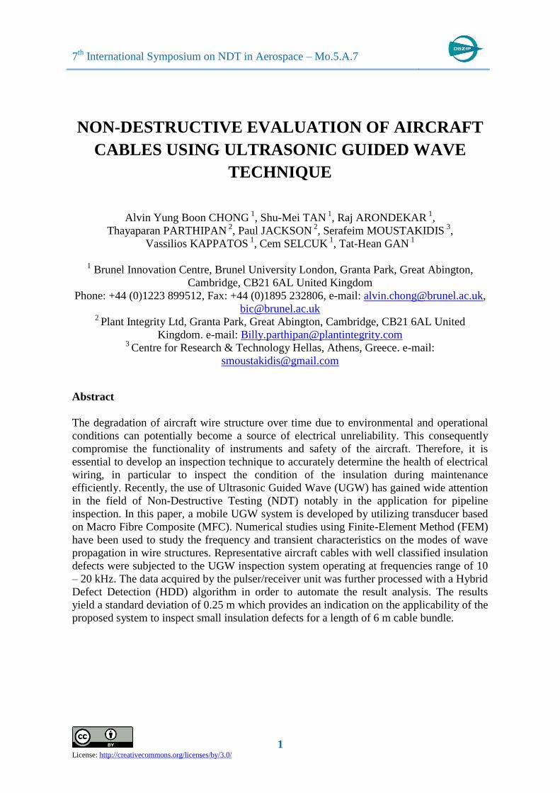
Hybrid Defect Detection (HDD) metrics for the defect Slit at 4.5 mm using
channel 2 computed at each single frequency
HDD at various frequencies
10 kHz
20 kHz
11 kHz
Copyright© Brunel Innovation Centre
12 kHz
Copyright© Brunel Innovation Centre
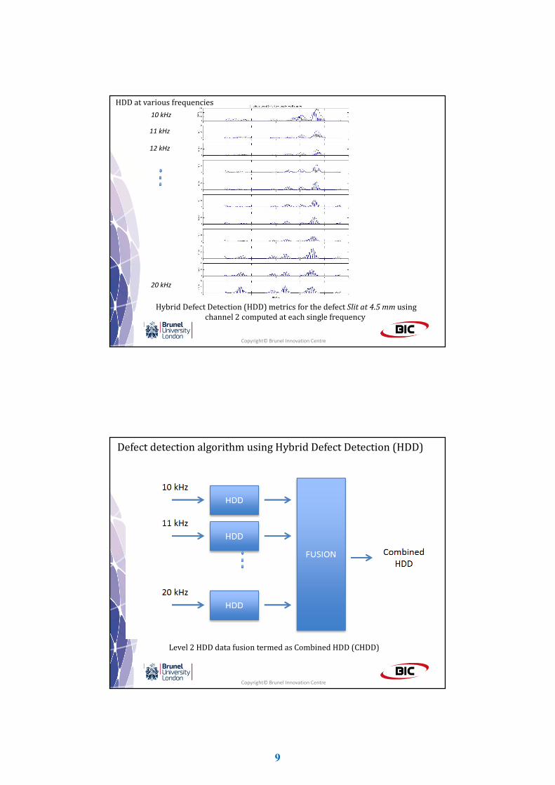
Defect detection algorithm using Hybrid Defect Detection (HDD)
Level 2 HDD data fusion termed as Combined HDD (CHDD)
9
Page 10
Combined Hybrid Defect Detection (CHDD)
Copyright© Brunel Innovation Centre
≈ 4.58 m
Final result clearly shown the defect at ca. 4.58 m
σ = ca. 0.25 m
Copyright© Brunel Innovation Centre
Larger slit defect at 5.5 m on wire 2
Final result clearly shown the defect at ca. 5.75 m
10
Page 11
Conclusionsi) Feasibility study of utilizing UGW for inspection of insulation defect
on aircraft cable (type 55D0211-10-9, AWG size 10) in a wire bundle
has been performed.
iv) UWG is well applicable to detect the defect (small slit) on the
insulation for a representative aircraft cable bundle of length
6m.
v) According to these results, insulation defect can be distinctively
observed with HDD algorithm. Standard deviation calculated to be
ca. 0.25 m for a 6 m cable length inspection.
ii) Numerical studies using Finite-Element Method (FEM) have been
used to study the frequency and transient characteristics on the
modes of wave propagation in wire structures.
iii) UWG system prototype have been developed based on
commercially available Macro Fibre Composite (MFC) transducers.
Copyright© Brunel Innovation Centre
Future work
Copyright© Brunel Innovation Centre
i) To investigate different types and extended length of aircraft cable
loom.
iii) Investigate further defect detection algorithm to improve
accuracy on defect localization
iv) To investigate different mode of testing operation such as online
condition monitoring to improve reliability of results.
Acknowledgements
ii) A better understanding of the influence of multiple insulation
defects at different locations in the wire.
The research leading to these results has received funding from the European Union's
Seventh Framework Programme managed by REA-Research Executive Agency
http://ec.europa.eu/research/rea ([FP7/2007-2013]) for the project entitled “Long
range ultrasonic inspection of aircraft wiring” – SAFEWIRE, under grant agreement no
[313357], FP7-SME-2012-1 (http://www.safewire.eu). SAFEWIRE is collaboration
between the following organisations: HORTEC, PLANT INTEGRITY LIMITED, ASSIST,
POLKOM BADANIA SP ZOO, ATARD, MARSHALL ADG, BRUNEL UNIVERSITY LONDON
and CERTH.
11
Page 12
Thank You!!
[email protected]
Copyright© Brunel Innovation Centre
Safewire project website: http://www.safewire.eu
12