(non-)Destructive high-rate tests on silicon strip modules Emulating LHC beam incidents using the PS booster and measuring the effect on a LHCb Velo silicon strip module Lars Eklund, on the behalf of the LHCb Collaboration
Transcript
(non-)Destructive high-rate tests on silicon strip modules
Emulating LHC beam incidents using the PS booster and measuring the effect on a LHCb Velo silicon strip
module
Lars Eklund, on the behalf of the LHCb Collaboration
14 September, 2009
L. Eklund, Vertex 2009 2
Outline
• Introduction– Motivation and previous publications
• The participants– The PS booster and the LHCb/VELO module
• The measurements– Observables and program
• The surprise– Results and interpretations
• Summary
14 September, 2009
L. Eklund, Vertex 2009 3
Motivation (1)
The LHC• Stored beam energy 102 - 103 times larger than any previous
accelerator• New machine, limited operational experience
The LHCb Velo• Very close to the beam: silicon sensors @ 7-30 mm distance
(moving!)• Located next to the injection line TI8• Designed and built: but operation procedures can be changed
– LV & HV on/off at injection?• Feedback to the machine
– Intensity limit at injection– Currently H/W 1011 protons and F/W 1010
14 September, 2009
L. Eklund, Vertex 2009 4
Motivation (2)
Possible beam incidents• Injection failures:
– incomplete or unsynchronized kicker fire => mostly Alice & LHCb
– wrong magnet settings in transfer line => mostly Alice & LHCb– wrong magnet settings in the LHC => everybody
– A set of standard measurements• I/V of both sensors• Noise & pedestal data• Test pulse data at +1.5, 0 and -150 V (for some shots)
– Insert the module, acquire during the shot• 14 consecutive triggers of front-end data• Voltage on hybrid GND and sensor bias via oscilloscope• Beam spot image via a a camera
– Repeat the same set of measurements• Shots on two sensor positions• Shots on five front-end chips (only LV on/off matters)
No m
easu
rable
dam
age
up to
• 9x1
012
@ 3
00V b
ias o
n th
e se
nsor
• 2x1
011
(LV o
n) o
n th
e FE ch
ips
14 September, 2009
L. Eklund, Vertex 2009 12
Beam images
Beam line camera on scintillating screen Combined R-Φ sensor front-end data
14 September, 2009
L. Eklund, Vertex 2009 13
I/V curves
• I/V curves in-situ between each shot– Superimpose temperature corrected I/V curves– Small increase probably due to accumulated dose– Rough estimate between first and last curve: 3x10¹² neq & 200 Gy
• Work in progress– Correlate with radiation monitoring data
14 September, 2009
L. Eklund, Vertex 2009 14
Thermal image: No hot-spots
The majority of the shots hit this area
14 September, 2009
L. Eklund, Vertex 2009 15
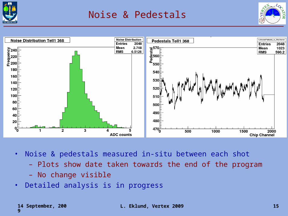
Noise & Pedestals
• Noise & pedestals measured in-situ between each shot– Plots show date taken towards the end of the program– No change visible
• Detailed analysis is in progress
14 September, 2009
L. Eklund, Vertex 2009 16
Test pulse response – post-zap
• Test pulse response– ‘booster’: in-situ after a few shots at 2x10⁹
– ‘lab’: lab measurement after the full program• Gain difference due to different analogue drivers/receivers• Bad channels identical to production QA
14 September, 2009
L. Eklund, Vertex 2009 17
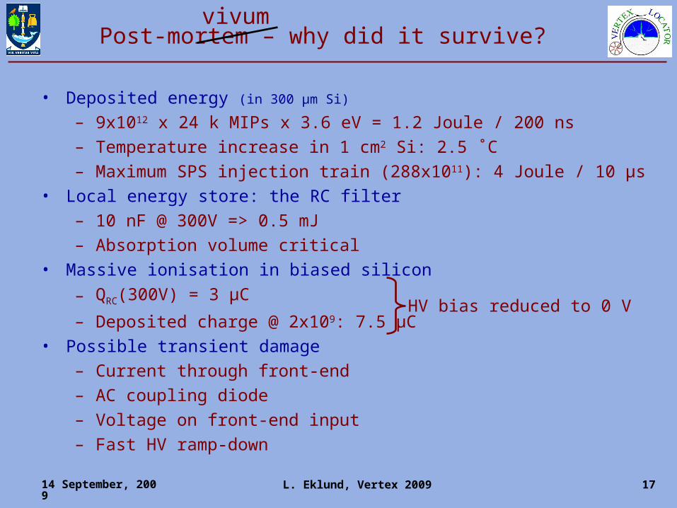
Post-mortem – why did it survive?
• Deposited energy (in 300 µm Si)
– 9x1012 x 24 k MIPs x 3.6 eV = 1.2 Joule / 200 ns– Temperature increase in 1 cm2 Si: 2.5 ˚C – Maximum SPS injection train (288x1011): 4 Joule / 10 µs
• Local energy store: the RC filter– 10 nF @ 300V => 0.5 mJ– Absorption volume critical
Rbias reduced to ~100kΩ/2048 via punch-through mechanism Still to large to play a role
14 September, 2009
L. Eklund, Vertex 2009 21
Shots on the FE chips
• 56 shots on the FE chips: 2x10⁹ – 2x10¹¹
• No destructive latch-up– Design rules include structures to prevent latch-up– Seems to be effective!
• SEU analysis in progress: none observed so far– Requires large energy deposited in small volume– Nuclear reactions necessary– Cross-section very low– Triple-redundant registers: corrected every 2 ns
14 September, 2009
L. Eklund, Vertex 2009 22
Summary
• The PS booster provided beam to emulate LHC beam incidents– 200 ns shots, 2x10⁹ to 9*1012 protons
• A VELO strip module was subject to a large number of shots– Two positions on the sensor, five FE chips
• Survived 9x10¹² protons on sensor with 300 V bias• Survived 2x10¹¹ protons on the FE chip• No visible change in performance
– The whole sensor responds as a unit– Large area sensor – many channels– CAC >> CRC (+CDET)– Protection diodes on the FE inputs– Triple-redundant registers in FE chips
• Analysis & measurement still in progress
14 September, 2009
L. Eklund, Vertex 2009 23
Back-up slides
14 September, 2009
L. Eklund, Vertex 2009 24
Total number of shots
Intensity
LV offHV off
LV onHV off
LV onHV
150V
LV onHV
300V
2*109 1 2 29+3 2
2*1010 1 1 1 1
2*1011 1 1 1 1
2*1012 1 1 1 1
9*1012 2 2 5 5
Shots on the sensor (position 1+2)
Intensity
Beetle 4 Beetle 5 Beetle 6 Beetle 7
LV on
LV off
LV on
LV off
LV on
LV off
LV on
LV off
2*109 - - 2 4 3 3 3 6
2*1010 3 3 5 3 3 3 6 6
2*1011 - 3 - - - - - -
Shots on the front-end chips
B2
B6
B0
B3
B4
B7
B5
B1
63 shots on the sensor
56 shots on the FE chips
14 September, 2009
L. Eklund, Vertex 2009 25
Beam size – seen by the Φ-sensor
“FWHM” of beam~80 strips of 70 m pitch~5.5 mm
Response to beam during initial 25 ns of beam rising edge in detector
14 September, 2009
L. Eklund, Vertex 2009 26
Fitting rising edge of all shots
• Termination of HV monitoring signal was improved during the program
• Rising edge not affected by termination• 150 V: Shots 3-5 & 24 @ 2e9, shot 10 @
2e10 and shot 14 @ 2e11 are less than 1 GV/s
• 300V & 9e12: Shots 34, 42, 44 are greater than 5 GV/s