71
Non-Domestic Heating, Cooling and Ventilation Compliance Guide May 2006 1st Edition

Published by NBS, part of RIBA Enterprises Ltd, and available from:
RIBA Bookshops Mail Order15 Bonhill StreetLondon EC2P 2EA
Telephone orders/General enquiries: 020 7256 7222Fax orders: 020 7374 2737Email orders: [email protected]
Or order online at:www.thebuildingregs.com
www.thenbs.comwww.thenbs.com
Non-Domestic Heating, Coolingand Ventilation Compliance Guide
May 20061st Edition
© Crown copyright 2006
The Approved Documents are published by NBS for the Department for Communities andLocal Government.
This publication has been approved by Ministers and has official status. Copyright in thecontents, the cover, the design and the typographical arrangement of this publication restswith the Crown unless otherwise stated. The contents of this publication may be reproducedfree of charge in any format or medium for the purposes of private research and studyor for internal circulation within an organisation. This is subject to the contents beingreproduced accurately and not in a way that implies official status. Any publisher wishingto reproduce the content of this publication must not use or replicate the DCLG logoor replicate the official version’s style and appearance, including the cover design, andmust not present their publication as being an official publication as this may confuse thepublic. The reproduced material must be acknowledged as Crown Copyright and the titleof the publication specified. The Office of the Deputy Prime Minister does not accept anyresponsibility for the accuracy and comprehensiveness of any other versions.
Any other use of the contents of this publication would require a copyright licence. Pleaseapply for a licence by writing to the Department for Communities and Local Government,Information Policy Team, St Clements House, 2-16 Colegate, Norwich NR3 1BQ.Fax 01603 723000 or email [email protected] information can be obtained from www.opsi.gov.uk.
ISBN-10 1 85946 226 XISBN-13 978 1 85946 226 3
Stock code 57646
RIBA Bookshops
66 Portland Place, London W1B 1AD. Telephone 020 7256 7222.
113-115 Portland Street, Manchester M1 6DW. Telephone 0161 236 7691.
Birmingham & Midland Institute, Margaret Street, Birmingham B3 3SP. Telephone 0121 233 2321.
RSUA, 2 Mount Charles, Belfast BT7 1NZ. Telephone 028 9032 3760.
Renew Rooms, 82 Wood Street, Liverpool L1 4DQ. Telephone 0151 707 4380.

ONLINE VERSION
ONLINE VERSION
ONLINE VERSION
1
The Building Regulations 2000As amended 2006
NON-DOMESTIC HEATING, COOLING AND VENTILATION COMPLIANCE GUIDE
COMPLIANCE WITH APPROVED DOCUMENTSL2A: NEW BUILDINGS OTHER THAN DWELLINGSAND L2B: EXISTING BUILDINGS OTHERTHAN DWELLINGS
1st edition May 2006
Non_domestic Heating.indd 1Non_domestic Heating.indd 1 17/5/06 16:06:5417/5/06 16:06:54

ONLINE VERSION
ONLINE VERSION
ONLINE VERSION
2
Acknowledgements
This document was compiled with the assistance of the following trade organisations:
ICOM Energy AssociationThe Heat Pump Association The Federation of Environmental Trade AssociationsThe Electric Heating and Ventilation AssociationThe Combined Heat and Power Association The Thermal Insulation Manufacturers and Suppliers Association
Published by NBS for the Department for Communities and Local GovernmentNBS is part of RIBA Enterprises Ltd.
RIBA Bookshops Mail Order15 Bonhill Street, London EC2P 2EATelephone orders/General enquiries: 020 7256 7222Fax orders: 020 7374 2737Email orders: [email protected] order online at www.thebuildingregs.com
RIBA Bookshops66 Portland Place, London W1B 1AD. Telephone 020 7256 7222.113-115 Portland Street, Manchester M1 6DW. Telephone 0161 236 7691.Birmingham & Midland Institute, Margaret Street, Birmingham B3 3SP. Telephone 0121 233 2321.RSUA, 2 Mount Charles, Belfast BT7 1NZ. Telephone 028 9032 3760.Renew Rooms, 82 Wood Street, Liverpool L1 4DQ. Telephone 0151 707 4380.
© Crown copyright 2006
Stock code 57646ISBN-10 1 85946 226 XISBN-13 978 1 85946 226 3
This publication has been approved by Ministers and has offi cial status. Copyright in the contents, the cover, the design and the typographical arrangement of this publication rests with the Crown unless otherwise stated. The contents of this publication may be reproduced free of charge in any format or medium for the purposes of private research and study or for internal circulation within an organisation. This is subject to the contents being reproduced accurately and not in a way that implies offi cial status.
Any publisher wishing to reproduce the content of this publication must not use or replicate the DCLG logo or replicate the offi cial version’s style and appearance, including the cover design, and must not present their publication as being an offi cial publication as thismay confuse the public. The reproduced material must be acknowledged as Crown Copyright and the title of the publication specifi ed.The Department for Communities and Local Government does not accept any responsibility for the accuracy and comprehensiveness of any other versions.
Any other use of the contents of this publication would require a copyright licence. Please apply for a licence by writing to the Offi ceof Public Sector Information, Information Policy Team, St Clements House, 2-16 Colegate, Norwich NR3 1BQ. Fax: 01603 723000 or email HMSOlicensing@cabinet-offi ce.x.gsi.gov.uk. Further information can be obtained from www.opsi.gov.uk.
Non_domestic Heating.indd 2Non_domestic Heating.indd 2 17/5/06 16:06:5517/5/06 16:06:55

ONLINE VERSION
ONLINE VERSION
ONLINE VERSION
3
Contents
PAGESection 1 Introduction 5
1.1 How to use this guide 6
1.2 Definitions relevant to space heating and domestic hot water systems 7
1.3 Requirements of Approved Documents L2A and L2B 8
1.4 General guidance for compliance with ADL2A and ADL2B 9
Section 2 Gas and oil-fired boilers 13
2.1 Introduction 13 2.2 Scope of the guidance 13 2.3 Definitions 13 2.4 Determining Seasonal Boiler Efficiency 13 2.5 Boilers in new buildings 17 2.6 Boilers in existing buildings 18 2.7 Glossary of boiler terminology 22
Section 3 Heat pumps 24
3.1 Introduction 24 3.2 Scope of the guidance 24 3.3 Definitions 24 3.4 Minimum provisions for heat pumps in new and existing buildings 25 3.5 Heating efficiency credits for heat pump systems 27
Section 4 Gas and oil-fired warm air heaters 30
4.1 Introduction 30 4.2 Scope of the guidance 30 4.3 Definitions 30 4.4 Minimum provisions for warm air heaters in new and existing buildings 31 4.5 Heating Efficiency Credits for warm air heaters in new and existing buildings 31
Section 5 Gas and oil-fired radiant technology 33
5.1 Introduction 33 5.2 Scope of the guidance 33 5.3 Definitions 33 5.4 Minimum provisions for radiant heaters 34 5.5 Heating Efficiency Credits for radiant heaters in new and existing buildings 34
Section 6 Combined heat and power (CHP) and community heating 36
6.1 Introduction 36 6.2 Scope of the guidance 36 6.3 Definitions 36 6.4 Minimum provisions for CHP in new and existing buildings 36 6.5 Additional guidance for community heating in new and existing buildings 37
Non_domestic Heating.indd 3Non_domestic Heating.indd 3 17/5/06 16:06:5517/5/06 16:06:55

ONLINE VERSION
ONLINE VERSION
ONLINE VERSION
4
PAGESection 7 Electric space heating 38
7.1 Introduction 38 7.2 Scope of the guidance 38 7.3 Definitions 38 7.4 Minimum provisions for electric space heating in new and existing buildings 38
Section 8 Domestic hot water 41
8.1 Introduction 41 8.2 Scope of the guidance 41 8.3 Definitions 42 8.4 Minimum provisions for domestic hot water systems in new and
existing buildings 43 8.5 Heating efficiency credits for domestic hot water systems 45
Section 9 Comfort cooling 48
9.1 Introduction 48 9.2 Scope of the guidance 48 9.3 Definitions 48 9.4 Minimum provisions for comfort cooling in new and existing buildings 49 9.5 Calculating the SEER for the NCM (SBEM) 50
Section 10 Air distribution systems 52
10.1 Scope of the guidance 52 10.2 Definitions 52 10.3 Minimum provisions for air handling units in new and existing buildings 53
Section 11 Pipework and duct insulation 55
11.1 Introduction 55 11.2 Scope of the guidance 55 11.3 Minimum provisions for insulation of pipes and ducts in new and
existing buildings 55
Section 12 Compliance checklist and data input into the National CalculationMethodology Tool 58
Section 13 Glossary 60
Appendix 1: Conversion factors 61
Appendix 2: Compliance checklist 62
Non_domestic Heating.indd 4Non_domestic Heating.indd 4 17/5/06 16:06:5517/5/06 16:06:55

ONLINE VERSION
ONLINE VERSION
ONLINE VERSION
5
Section 1 Introduction
Part L of Schedule 1 to the Building Regulations1 is concerned with the conservation of fuel and power in buildings. For buildings other than dwellings Part L is supported by two Approved Documents,Approved Document L2A (ADL2A) and Approved Document L2B (ADL2B). In addition to Part L, other Regulations also bear on the energy performance of buildings and their heating systems. ADL2A gives guidance on how to satisfy the energy performance provisions of the Building Regulations for new buildings. ADL2B gives guidance on how to satisfy the energy performance provisions of the Building Regulations for work in existing buildings. Both Approved Documents repeat the relevant regulatory requirements verbatim in various places distinguished by a green background with theaim of making them complete references for ordinary purposes. In cases of doubt however it maybe necessary to refer direct to the Building Regulations as amended.
These Approved Documents were published in 2006 in support of the amendments to the Building Regulations, SI 2006/652. The amendment will come into force on 06 April 2006.
The revised Approved Documents, ADL2A and ADL2B, are more strategic in nature and rely on ‘second-tier’ documents to provide detailed information on how to comply with the requirements of Part L of the Regulations.
This guide (the ‘Non-Domestic Heating, Cooling and Ventilation Compliance Guide’) is a second-tier document referred to in ADL2A and ADL2B as a source of guidance on the means of complying with the requirements of Building Regulations Part L for space heating systems, hot water systems, cooling and ventilation systems. The guide was prepared by industry bodies and the Offi ce of the Deputy Prime Minister (ODPM)*; it covers the conventional means of providing primary space heating, domestic hot water and comfort cooling and ventilation for buildings in use in England and Wales at the time of writing. When appropriate, the guide identifi es the different requirements for systems in new build and those in existing buildings where work is being undertaken.
The guide outlines the minimum provisions for compliance with Part L for each type of heating, hot water, cooling or air distribution system as follows:
• The minimum provisions for effi ciency of the plant that generates heat, hot water or cooling.
• The minimum provisions for controls to ensure that the system is not generating heat, hot water or cooling unnecessarily or excessively.
• A set of additional measures which may improve the effi ciency of the plant; these are non-prescriptive and may be either required or optional depending on the type of plant.
• Minimum provisions for other factors affecting the safety or energy effi ciency of the system.
• The minimum provision for insulation of pipes and ducts serving space heating, hot waterand cooling systems.
• Minimum provisions for acceptable specifi c fan power ratings for fans serving airdistribution systems.
The Building Regulations Part L now requires the energy performance of buildings other than dwellings to be calculated using the National Calculation Methodology (NCM)2. The NCM defi nes the procedure for calculating the annual energy use for a proposed building (based on a range of factors including the properties of the walls, fl oors, roofs and glazing as well as the building services) and comparing it with the energy use of a comparable ‘notional’ building. The NCM also calculates the rate of carbon emissions from the building which should not be greater than its Target Emission Rate as described in Approved Documents L and also calculated by the NCM. The NCM can be implementedthrough accredited simulation software or through the Simplifi ed Building Energy Model (SBEM)3.
* On 5th May 2006 the responsibilities of the Offi ce of the Deputy Prime Minister (ODPM) were passed to the Department for Communities and Local Government (DCLG).
1 The Building Regulations, SI 2006/652 including Part L of Schedule 1 apply in England and Wales. Separate Regulations apply in Scotland and Northern Ireland and may require different provisions from those signalled in this Guide as the minimum regulatory requirement.
2 The National Calculation Methodology for Part L, ODPM, 2006. ISBN 1 85946 227 8.3 The Simplifi ed Building Energy Model (SBEM) tool can be downloaded from www.odpm.gov.uk
Non_domestic Heating.indd 5Non_domestic Heating.indd 5 17/5/06 16:06:5617/5/06 16:06:56

ONLINE VERSION
ONLINE VERSION
ONLINE VERSION
6
This guide identifi es the input parameters that are required by the accredited NCM models (e.g. SBEM), for space heating, hot water, comfort cooling and ventilation systems, in order to calculate the annual energy performance.
The key requirements for compliance with Part L and Approved Documents L2A and L2B and thekey parameters for input into the accredited NCM models (e.g. SBEM) are summarised in a Compliance Checklist.
1.1 How to use this guide
This document provides guidance on the means of complying with the requirements of Building Regulations Part L for conventional space heating systems, hot water systems, cooling and ventilation systems in non-domestic buildings.
The guide addresses each technology in a separate section. These technology-specifi c sections are stand-alone but should be read alongside this introduction, and the generic sections that follow:
• Section 1.2 Defi nitions relevant to space heating and domestic hot water systems
• Section 1.3 Requirements of Approved Documents L2A and L2B
• Section 1.4 General guidance for compliance with ADL2A and ADL2B
• Section 10 Air-handling units (if applicable)
• Section 11 Pipework and duct insulation
• Section 12 Compliance checklist and data input into the National Calculation Methodology tool
• Section 13 Glossary The Non-domestic Heating, Cooling and Ventilation Compliance Guide identifi es the minimum standards of provision that meet the requirements of Part L for systems in new build and those in existing buildings when work is being undertaken. The guide covers a range of frequently occurring situations but alternative means of achieving compliance may be possible. The status of alternative provisions is explained in the ‘Use of Guidance’ sections at the front of the Approved Documents.
Non_domestic Heating.indd 6Non_domestic Heating.indd 6 17/5/06 16:06:5617/5/06 16:06:56

ONLINE VERSION
ONLINE VERSION
ONLINE VERSION
7
Section 1.2 Defi nitions relevant to space heating and domestic hot water systems
The following generic defi nitions are used in this document. Specifi c defi nitions are also applicable to each type of heating plant or system depending on the relevant test procedures and are included in the relevant technology section of this guide.
It is important to note that this document deals only with the equipment that converts fuel or electricityto heat (the ‘heat generator’) and factors that improve the effi ciency of the heat generator. Other aspectsof the heat delivery system are addressed by the accredited NCM model (e.g. SBEM). Defi nitions relevant to cooling and ventilation systems are given in Section 9 and Section 10 of this guide, respectively.
Heat Generator – a device for converting fuel and/or electricity into heat, e.g. boiler, radiant heater.
Heat Generator Effi ciency – Heat Generator Effi ciency is the ratio of useful heat output to energy input in the fuel (based on gross calorifi c value) or electricity delivered to the heat generator as determined by the appropriate testing methods for that type of heat generator.
Heat Generator Seasonal Effi ciency – the Heat Generator Seasonal Effi ciency is the estimated seasonal ratio of heat input to heat output from the heat generator. This will depend on the Heat Generator Effi ciency and the operating mode of the heat generator(s) over the heating season. For example, in the case of boilers it is a ‘weighted’ average of the effi ciencies of the boiler at 30% and 100% of the boiler output. For other technologies the Heat Generator Seasonal Effi ciency may bethe same as the Heat Generator Effi ciency.
Heating Effi ciency Credits – these are awarded for the provision of specifi c measures. Different credits apply to measures possible for each of the heating or hot water technologies. Heating Effi ciency Credits are added to the Heat Generator Seasonal Effi ciency to obtain an Effective Heat Generating Seasonal Effi ciency.
Effective Heat Generating Seasonal Effi ciency – the Effective Heat Generating Seasonal Effi ciencyis calculated by adding the Heating Effi ciency Credits, where applicable, to the Heat Generator SeasonalEffi ciency as described in Equation 1. The Effective Heat Generating Seasonal Effi ciency is the minimumeffi ciency that must be met by the heat generator and associated heating effi ciency credits.
Effective Heat Generating Seasonal Effi ciency =Heat Generator Seasonal Effi ciency + Heating Effi ciency Credits Equation 1
Minimum controls package – a package of controls specifi c to each technology that represents the minimum provision for controls to reduce carbon emissions from a space heating or hot water system. Heating Effi ciency Credits are not available for the minimum controls package.
Additional controls and other measures – controls or other measures that go beyond the required minimum controls package and for which heating effi ciency credits are available. For some types of heat generators (with an inherently low effi ciency) the additional measures are required in order to achieve the minimum Effective Heat Generating Seasonal Effi ciency.
Alternatively these additional measures can be used to exceed the required minimum performance level to improve the overall energy performance of the building.
Space heating system – the complete system that is installed to provide heating to the space.It includes the heating plant and the system by which the heating medium effects heating in the relevant zone. Heat losses from the distribution system can be addressed by reference to theTIMSA HVAC Insulation Guide4.
Domestic hot water system – a local or central system for providing hot water for use by building occupants.
4 TIMSA HVAC Insulation Guide www.timsa.org.uk
Non_domestic Heating.indd 7Non_domestic Heating.indd 7 17/5/06 16:06:5617/5/06 16:06:56

ONLINE VERSION
ONLINE VERSION
ONLINE VERSION
8
Section 1.3 Requirements of Approved DocumentsL2A and L2B
The Building Regulations that bear on energy effi ciency are repeated for easy reference at the frontof both Approved Document L2A and Approved Document L2B before the sections giving technical guidance on compliance. The Approved Documents can be viewed on www.communities.gov.uk.
For new buildings the provision of heating and hot water services systems has to be considered as part of the overall design. For heating and hot water services systems works in existing buildings provision can be considered in isolation. Both Approved Documents refer to this publication as the source of detailed guidance on what is reasonable provision.
This document is given as a source of guidance on showing compliance in paragraph 41 in Approved Document L2B.
Non_domestic Heating.indd 8Non_domestic Heating.indd 8 17/5/06 16:06:5717/5/06 16:06:57

ONLINE VERSION
ONLINE VERSION
ONLINE VERSION
9
Section 1.4 General guidance for compliance withL2A and L2B
Compliance with the Approved Documents, L2A and L2B, depends on meeting the minimum provisionsfor the following:
• A minimum Heat Generator Seasonal Effi ciency of the device that generates heat or hot water. The minimum Heat Generator Seasonal Effi ciency for particular types of space heating and hot water systems is specifi ed in Table 1. AND
• For heating and hot water systems, a minimum Effective Heat Generating Seasonal Effi ciency as detailed in each technology-specifi c section of the guide. This will require the use of heating effi ciency credits where the Heat Generator Seasonal Effi ciency is less than the minimum requirement for the Effective Heat Generating Seasonal Effi ciency. AND
• For cooling systems, a minimum Energy Effi ciency Ratio as detailed in the cooling sectionof the guide. The minimum Energy Effi ciency Ratio for particular types of cooling plant is specifi ed in Table 1. AND
• A minimum controls package to ensure that the system is not generating heat, hot wateror cooling unnecessarily or excessively. AND
• Additional measures which may improve the effi ciency of the heat generator or cooling generator from a non-prescriptive list. This is necessary only for particular technologies.By providing additional measures heating plant effi ciency credits can be gained. AND
• Insulation, to avoid excessive heat loss from pipes and ducts serving space heating or hot water systems, and to avoid heat gain by pipes and ducts serving cooling systems. AND
• An acceptable specifi c fan power for fans serving air distribution systems. The maximum permissible Specifi c Fan Power for particular types of air distribution systems is specifi ed in Table 1. AND
• Other requirements for factors affecting the safety or energy effi ciency of the system.
Note that the minimum provision for the energy effi ciency of heating plant is expressed in terms of the Effective Heat Generating Seasonal Effi ciency. Recognition for exceeding the minimum provisions in new buildings is refl ected in an improved energy performance rating when calculated in the accredited NCM tool. Similarly the Heat Generator Seasonal Effi ciency and the minimum controls package both represent the minimum requirement for compliance with L2A and L2B.
Table 1 summarises the minimum provisions for the energy effi ciency of the types of heating, hot water and cooling generator and ventilation systems covered by the Non-domestic Heating, Cooling and Ventilation Compliance Guide. Further guidance on how to comply with the values in Table 1 is given in the relevant technology sections that follow. Later sections of this document also describe the controls required for each type of heating, hot water or cooling system, additional controls and associated Heating Effi ciency Credits and any other requirements.
Non_domestic Heating.indd 9Non_domestic Heating.indd 9 17/5/06 16:06:5717/5/06 16:06:57

ONLINE VERSION
ONLINE VERSION
ONLINE VERSION
10
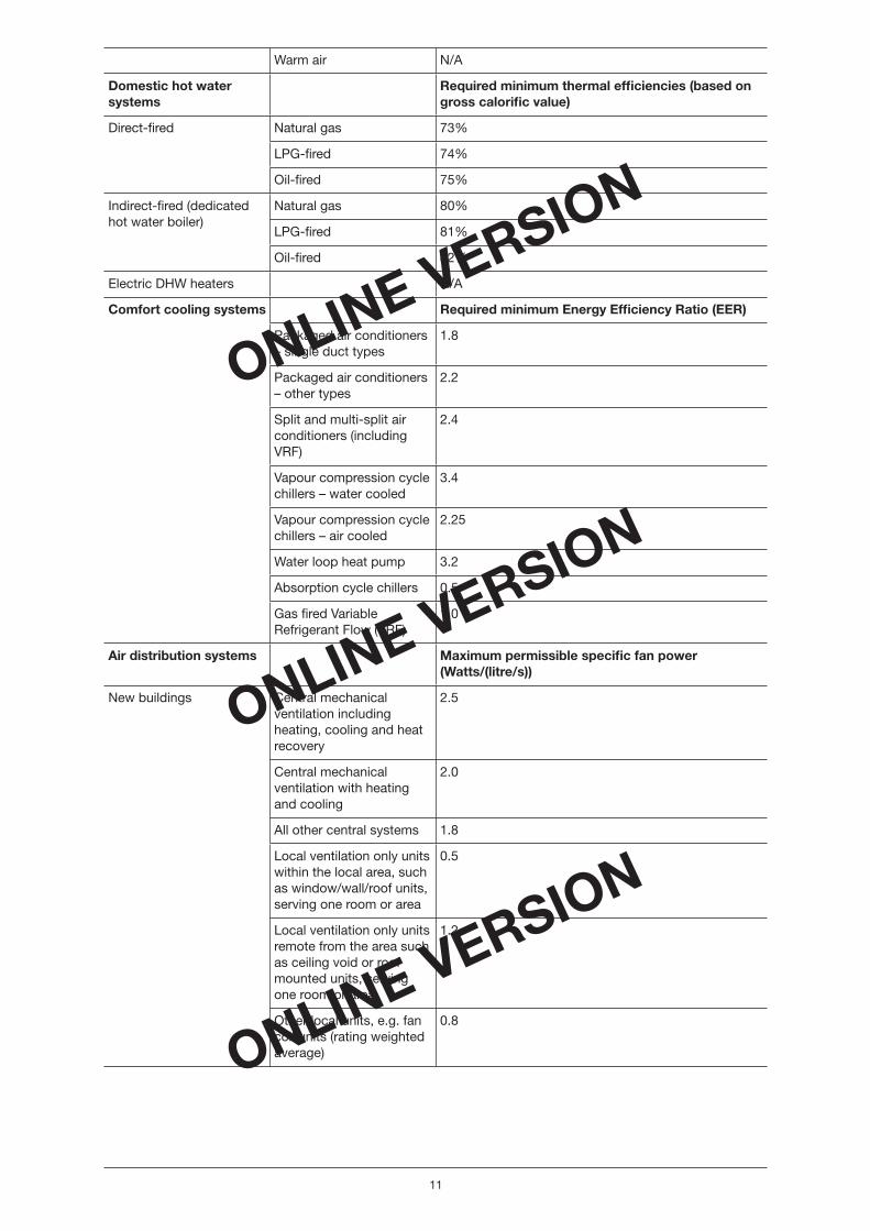
Table 1 Minimum Heat Generator Seasonal Effi ciency for primary heating systems,hot water systems, minimum Energy Effi ciency Ratios for cooling systems and maximum permissible specifi c fan powers for air distribution systems Primary spaceheating system
System type Required Minimum Boiler Seasonal Effi ciency (based on gross calorifi c value)
Boilers in new build Natural gas Single boiler system – 0.84Multiple-boiler system – 0.80 for any individual boiler and 0.84 for the overall multi-boiler system
LPG Single boiler system – 0.84 Multiple-boiler system – 0.80 for any individual boiler and 0.84 for the overall multi-boiler system
Oil Single boiler system – 0.84Multiple-boiler system – 0.80 for any individual boiler and 0.84 for the overall multi-boiler system
Boilers in existing buildings
Natural gas 80%
LPG 81%
Oil 82%
Gas and oil-fi red warm air systems
Required minimum thermal effi ciency (based on gross calorifi c value)
Gas-fi red forced convection heater without a fan complying with EN 621
80%
Fan assisted gas-fi red forced convection complying with EN 1020
80%
Direct gas-fi red forced convection heater complying with EN 525
90%
Oil fi red forced convection 80%
Radiant heaters Luminous (unfl ued) 85.5%
Non-luminous (unfl ued) 85.5%
Non-luminous fl ued 73.8%
Multi-burner radiant heaters
80%
Heat pumps Required Minimum Heating COP (at design condition)
All types except absorption heat pumps and gas engine heat pumps
2.0
Absorption heat pumps 0.5
Gas engine driven heat pumps
1.0
CHP Required Minimum CHPQA Quality Index (CHPQA QI)
All types 105
Electric (primary) heating Boiler N/A
Non_domestic Heating.indd 10Non_domestic Heating.indd 10 17/5/06 16:06:5717/5/06 16:06:57
ONLINE VERSION
ONLINE VERSION
ONLINE VERSION
11
Warm air N/A
Domestic hot water systems
Required minimum thermal effi ciencies (based on gross calorifi c value)
Direct-fi red
Natural gas 73%
LPG-fi red 74%
Oil-fi red 75%
Indirect-fi red (dedicated hot water boiler)
Natural gas 80%
LPG-fi red 81%
Oil-fi red 82%
Electric DHW heaters N/A
Comfort cooling systems Required minimum Energy Effi ciency Ratio (EER)
Packaged air conditioners – single duct types
1.8
Packaged air conditioners – other types
2.2
Split and multi-split air conditioners (including VRF)
2.4
Vapour compression cycle chillers – water cooled
3.4
Vapour compression cycle chillers – air cooled
2.25
Water loop heat pump 3.2
Absorption cycle chillers 0.5
Gas fi red Variable Refrigerant Flow (VRF)
1.0
Air distribution systems Maximum permissible specifi c fan power (Watts/(litre/s))
New buildings Central mechanical ventilation including heating, cooling and heat recovery
2.5
Central mechanical ventilation with heating and cooling
2.0
All other central systems 1.8
Local ventilation only units within the local area, such as window/wall/roof units, serving one room or area
0.5
Local ventilation only units remote from the area such as ceiling void or roof mounted units, serving one room or area
1.2
Other local units, e.g. fan coil units (rating weighted average)
0.8
Non_domestic Heating.indd 11Non_domestic Heating.indd 11 17/5/06 16:06:5817/5/06 16:06:58

ONLINE VERSION
ONLINE VERSION
ONLINE VERSION
12
Existing buildings Central mechanical ventilation including heating, cooling and heat recovery
3.0
Central mechanical ventilation with heating and cooling
2.5
All other central systems 2.0
Local ventilation only units within the local area, such as window/wall/roof units, serving one room or area
0.5
Local ventilation only units remote from the area such as ceiling void or roof mounted units, serving one room or area
1.5
Other local units, e.g. fan coil units (rating weighted average)
0.8
Non_domestic Heating.indd 12Non_domestic Heating.indd 12 17/5/06 16:06:5817/5/06 16:06:58
ONLINE VERSION
ONLINE VERSION
ONLINE VERSION
13
Section 2 Gas and oil-fi red boilers
2.1 Introduction
This section outlines the minimum provisions needed to comply with Part L when space heating in new build and in existing buildings is provided by boiler systems. It addresses the relevant boiler types and measures, such as controls, for which the associated energy effi ciency benefi ts may be added to the Heat Generator Seasonal Effi ciency.
2.2 Scope of the guidance
The guidance given here applies to commercial boilers for use in wet central heating systems as follows:
• Natural gas boilers.• Liquid petroleum gas (LPG) boilers.• Oil-fi red boilers.
It does not cover the use of:
• Steam boilers (these are used primarily for processes rather than the provision of space heating). • Electric boilers (see Section 7 of this document for guidance on electric heating).
2.3 Defi nitions
The terminology used to describe effi ciencies for boiler systems is detailed below. In this section a heat generator refers to a boiler.
Boiler Effi ciency – the energy delivered by the water as it leaves the boiler (or boilers in multi-boiler installations) to supply the heat emitters divided by the energy (based on gross calorifi c value) in the fuel delivered to the boiler expressed as a percentage. It is an expression of the boiler performance and excludes boiler and auxiliary controls energy, pumps, boiler room ventilation fans, mechanical fl ue extraction fans and fan dilution systems.
The boiler effi ciency is measured according to the standards that are used to demonstrate compliance with the Boiler Effi ciency Directive5.
Economiser – a device including a secondary heat exchanger fi tted on, or near to, a boiler providing additional heat transfer capacity. For the purpose of this guide, any boiler which will be suppliedwith an economiser should have the economiser fi tted when the boiler effi ciency is tested according to the standards that are used to demonstrate compliance with the Boiler Effi ciency Directive if the effi ciency benefi ts of the economiser are to be included in the calculation of Boiler Effi ciency using Equation 2, 3.1, or 3.2 and 3.3 (as appropriate).
2.4 Determining Seasonal Boiler Effi ciency
Seasonal Boiler Effi ciency for single boiler systems and multiple-boiler systems using identical boilers – for boilers the relevant heat generator seasonal effi ciency is the seasonal boiler effi ciency. The Seasonal Boiler Effi ciency is a ‘weighted’ average of the effi ciencies of the boiler at 15%, 30% and 100% of the boiler output (the effi ciency at 15% is taken to be the same as that at 30%). Thisis usually quoted by the boiler manufacturer. Note that the effi ciency based on net calorifi c value should be converted to that based on gross calorifi c value using the appropriate conversion factorin Appendix 1.
5 Council Directive 92/42/EEC (the Boiler Effi ciency Directive) relates to the effi ciency requirements for new hotwater boilers fi red with liquid or gaseous fuels. The associated UK legislation is the Boiler (Effi ciency) Regulations1993 (SI 1993/3083), amended by the Boiler (Effi ciency) (Amendment) Regulations 1994 (SI 1994/3083).
Non_domestic Heating.indd 13Non_domestic Heating.indd 13 17/5/06 16:06:5817/5/06 16:06:58

ONLINE VERSION
ONLINE VERSION
ONLINE VERSION
14
The Boiler Effi ciencies, measured at 100% load and at 30%, are used as the basis for calculating the Seasonal Boiler Effi ciency as described by Equation 2. The weighting factors given in Equation 2 should be used as they represent typical seasonal operating conditions for the boiler.
Equation 2 applies in the following conditions:
• single boiler systems where the boiler output is �400kW and the boiler will operate on a low temperature system;
• multiple-boiler systems where all individual boilers have identical effi ciencies AND where the output of each boiler is �400kW operating on low temperature systems.
For boilers with an output >400kW the manufacturer’s declared effi ciencies should be used.
Seasonal Boiler Effi ciency Equation 26
= 0.81�30% + 0.19�100%
Where the terms in Equation 2 are defi ned as follows:
• �30% is the gross boiler effi ciency measured at 30% load;• �100% is the gross boiler effi ciency measured at 100% load.
Seasonal Boiler Effi ciency for a multiple-boiler system replacing an existing installation where the component boilers have non-identical effi ciencies – where more than one boiler is installed on the same heating system and the effi ciencies of the boilers are not all identical, Equation 3.1 should be used to calculate the overall Seasonal Boiler Effi ciency. All boilers should be included in the calculation, even when some are identical.
Seasonal Boiler Effi ciency (multiple-boiler Equation 3.1systems with non-identical boilers)= �
OSBE = �
SBE.R
�R
Where the terms in Equation 3.1 are defi ned as follows:
• �OSBE
is the gross overall seasonal boiler effi ciency, being a weighted average with respect to boiler output, of the individual seasonal boiler effi ciencies;
• �SBE
is the gross seasonal boiler effi ciency of each individual boiler calculated usingEquation 2;
• R is the rated output in kW of each individual boiler (at 80ºC/60ºC).
Seasonal Boiler Effi ciency for a multi-boiler system in a new building – in the case of multiple boilers in new build, the more accurate three-step method described below should be used to calculate the overall seasonal boiler effi ciency for multiple-boilers. These steps can readily be programmed into a spreadsheet to automate the calculation.
Step 1
Determine which boilers are operating at what individual part load level at each of the three system part load conditions of 15%, 30% and 100%. For example, if the total system output is made up of three equally sized boilers, at 15% of system output, the lead boiler will be operating at 45% of its rated output, with the other two boilers switched off.
Step 2
Determine the effi ciency at which each individual boiler is operating at each of the above operating conditions. In the above example, the effi ciency of the boiler operating at 45% can be determined by linear interpolation between its effi ciencies at 30% and 100% of rated output. Where it is necessary to determine the effi ciency of an individual boiler at 15% of rated output, this should be taken as the same as the effi ciency at 30% of rated output. (Note that the effi ciency at 15% of rated output will only be needed if a single boiler meets the full design output.)
6 This equation assumes that the effi ciency at 15% load is taken to be the same as that at 30% (and therefore the equation has been simplifi ed accordingly).
Non_domestic Heating.indd 14Non_domestic Heating.indd 14 17/5/06 16:06:5917/5/06 16:06:59

ONLINE VERSION
ONLINE VERSION
ONLINE VERSION
15
Step 3
Calculate the overall operating effi ciency at each of the system part load conditions. This is calculated by the following formula:
p =
Qp
qb, p
b, p�
Equation 3.2
where �p = the system effi ciency at part load condition p, i.e. 15%, 30% and 100% of system rated output. Qp = the system heat output at part load condition p. qb,p = the individual boiler heat output at system part load condition p. �b,p = the individual boiler effi ciency at system part load condition p.
Calculate the overall seasonal boiler effi ciency as the weighted average of the effi ciencies at the three load conditions using the following equation: �OSBE = 0.36� p = 15% + 0.45� p = 30% + 0.19� p = 100% Equation 3.3
Table 2 is a worksheet that can be used to follow through these calculations. Table 3 shows a completedexample calculation using this worksheet, for the case where a system with a rated output of 600kW is served by three boilers, each rated at 250kW. The fi rst two boilers are condensing boilers, with the third being a standard boiler. Because the installation is oversized (750kW compared to 600kW), even at full system output, the fi nal boiler is only operating at 40% output (100/250).
The notes at the foot of Table 3 illustrate how the various values are calculated.
Table 2 Worksheet for calculating the overall seasonal boiler effi ciency ofa multiple-boiler system using the alternative three-step method
Effi ciency at stated % of boiler output
Boiler output at stated% of system output
Boiler effi ciency at stated% of system output
Boilerno.
Rating kW
@100% @30% 15% 30% 100% 15% 30% 100%
1
2
3
4
5
6
7
8
System effi ciency at part load
Weighting factor 0.36 0.45 0.19
Overall seasonal boiler effi ciency
Non_domestic Heating.indd 15Non_domestic Heating.indd 15 17/5/06 16:06:5917/5/06 16:06:59

ONLINE VERSION
ONLINE VERSION
ONLINE VERSION
16
+250*100%
86.00%
250*100%
86.00%+ ] = 85.41%
250*40%
85.00%600/ [
Table 3 Example calculation of the overall seasonal boiler effi ciency of a multiple boiler system in a new building
Effi ciency at stated % of boiler output
Boiler output at stated % of system output
Boiler effi ciency at stated % of system output
Boilerno.
Rating kW
@100% @30% 15% 30% 100% 15% 30% 100%
1 250 86.0 90.0 36.0% 72.0% 100.0% 89.66%1 87.60% 86.00%
2 250 86.0 90.0 0.0% 0.0% 100.0% 90.00% 90.00% 86.00%
3 250 85.0 85.0 0.0% 0.0% 40.0% 77.00% 77.00% 85.00%
System effi ciency at part load 89.66% 87.60% 85.41%2
Weighting factor 0.36 0.45 0.19
Overall seasonal boiler effi ciency 87.28%3
Notes 1: calculated by linear interpolation
1,30% = + ( 30% – )* 30% 100%
(36% – 30%)
(100% – 30%) 2: calculated by dividing the thermal output of the system (600kW) by the rate of fuel consumption, which is
given by the sum of the boiler outputs divided by their individual operating effi ciency, i.e.
3: calculated as the weighted average, i.e. 89.66%*0.36 + 87.60%*0.45 + 85.41%*0.19 = 87.92%
Effective Heat Generating Seasonal Effi ciency – this is equivalent to the heat generator seasonal effi ciency, that is the Boiler Seasonal Effi ciency (as calculated by Equation 2 for individual boilers or by Equation 3.1 plus any heating effi ciency credits that apply for existing installations.
Economisers – where the boiler manufacturer supplies an economiser as part of the boiler (as a matched package) and the combined unit is tested to the standards needed to demonstrate compliancewith the Boiler Effi ciency Directive, the effect of this on the boiler effi ciency at 30% and 100% of the boiler output may be taken into account in the values used for the calculation of the Heat Generator Seasonal Effi ciency (Seasonal Boiler Effi ciency) using Equations 2 or 3.1 or the three-step method and Equations 3.2 and 3.3, as appropriate.
Non_domestic Heating.indd 16Non_domestic Heating.indd 16 17/5/06 16:07:0017/5/06 16:07:00

ONLINE VERSION
ONLINE VERSION
ONLINE VERSION
17
2.5 Boilers in new buildings
Background
It is essential that any new building will be provided with high effi ciency condensing and/or non-condensing boilers and the minimum provisions with respect to the heat generator seasonal effi ciency refl ect this requirement.
Commercial heating systems are inherently more complicated than domestic systems with a wider range of temperatures and heat emitters. The selection of condensing or non-condensing boilers will therefore need to be determined by application and physical restraints.
Condensing boilers will meet projected effi ciencies only when they operate with a system return temperature between 30˚C and 40˚C for 80% of the annual operating hours. With a return temperatureof 55˚C and above, condensing boilers will not produce condensate and will have similar effi ciencies to non-condensing high effi ciency boilers. Some systems are suitable for outside compensator control that allows return temperatures to fall into the condensing range for some periods of the heating season and these may be best served by a mixture of condensing and non-condensing boilers.
In the case of boilers in new buildings the minimum Heat Generator Seasonal Effi ciency is equivalent to the minimum Effective Heat Generating Seasonal Effi ciency.
Minimum provisions for boilers in new buildings
In order to comply with ADL2A, when installing boiler plant in new buildings the following minimum provisions should be met:
a. Where a single boiler is used to meet the heat demand, the boiler should achieve a boiler seasonal effi ciency (gross calorifi c value) as given in Equation 2, of not less than 84%; OR
b. For multiple-boiler systems, each boiler should have a boiler seasonal effi ciency of notless than 80% (gross calorifi c value) as defi ned by Equation 2; AND the overall boiler seasonal effi ciency of the multi-boiler system, as defi ned by Equation 3.1 for an existing installation orthe three-step method and Equations 3.2 and 3.3 for new building installations, should be noless than 84%; AND
c. The relevant minimum controls package in Table 4 should be adopted.
Non_domestic Heating.indd 17Non_domestic Heating.indd 17 17/5/06 16:07:0017/5/06 16:07:00

ONLINE VERSION
ONLINE VERSION
ONLINE VERSION
18
Table 4 Minimum controls package for new boilers or multiple-boiler systems (depending on boiler plant output or combined boiler plant output)Boiler plant output Minimum controls
package Minimum controls package
<100kW A • Timing and temperature demand control which should bezone-specifi c where the building fl oor area is greater than 150m2
• Weather compensation except where a constant temperature supply is required
100kW to 500kW B • Controls package A above PLUS
• Optimal start/stop control is required with night set-back OR frost protection outside occupied periods
• Boiler with two stage high/low fi ring facility or multiple boilers should be installed to provide effi cient part-load performance
For multiple boilers, sequence control should be provided AND boilers, by design or application, should have limited heat loss from non-fi ring modules, for example by using isolation valves or dampers.For boilers with low standing losses isolation valves and dampers would not be required
Individual boilers, by design or application, should have limited heat loss from non-fi ring modules, for example by using isolation valves or dampers.
>500kW – individual boilers
C • Controls package A above AND Controls package B PLUS:
• The burner controls should be fully modulating for gas-fi red boilers or multi-stage for oil-fi red boilers
The correct effi ciency to input into the accredited NCM tool when calculating the energy performance rating is the effective heat-generating seasonal effi ciency. For boilers in new buildings there are no Heating Effi ciency Credits available and the Effective Heat Generating Seasonal Effi ciency is therefore the same as the Heat Generator Seasonal Effi ciency.
2.6 Boilers in existing buildings
Background
Boiler effi ciencies have improved markedly over recent years. A boiler meeting the minimum required effi ciency in 1989 would have a Boiler Seasonal Effi ciency of approximately 65%, whereas a boiler meeting the minimum requirements of the Boiler Effi ciency Directive would have a Boiler Seasonal Effi ciency of approximately 78.5% (both based on gross calorifi c value). This improvement in boiler effi ciency represents an energy saving of approximately 17%.
This guidance recognises that in many cases using condensing boiler technology in existing buildings would be either technically impractical (because of fl ueing constraints) or economically unviable. For this reason non-condensing boilers may be used provided that the minimum provisions for effi ciency are met as given in this section.
Minimum provisions for replacement boilers
In order to comply with ADL2B, when installing boiler plant in existing buildings the following minimum provisions should be met:
a. Each boiler (regardless of whether it is in a single-boiler system or part of a multiple-boiler system) should have a minimum Boiler Seasonal Effi ciency (gross calorifi c value), as calculated by Equation 2, no worse than the relevant value in Table 5;
Non_domestic Heating.indd 18Non_domestic Heating.indd 18 17/5/06 16:07:0017/5/06 16:07:00

ONLINE VERSION
ONLINE VERSION
ONLINE VERSION
19
b. For multiple-boiler systems the minimum seasonal boiler effi ciency as determined by Equation 3.1 should be no worse than the relevant value in Table 5;
AND c. A minimum controls package should be adopted as described in Table 6; AND
d. The Effective Heat Generating Seasonal Effi ciency should be no less than the relevant valuein Table 5. Additional measures from Table 7 must be adopted to gain Heating Effi ciency Creditsif the Boiler Seasonal Effi ciency is less than the relevant value of the Effective Heat GeneratingSeasonal Effi ciency.
Table 5 Required Minimum Effective Heat Generating Seasonal Effi ciencies andminimum boiler seasonal effi ciency for boiler systems in existing buildingsFuel type Minimum Effective Heat
Generating Seasonal Effi ciency (% gross calorifi c value)
Minimum Boiler Seasonal Effi ciency(% gross calorifi c value)
Gas (Natural) 84 80
Gas (LPG) 85 81
Oil 86 82
Table 6 Minimum controls package for replacement boilers in existing buildings Minimum controls package for replacement boilers
Suitable controls
Zone controls Zone control is required only for buildings where the fl oor area is greater than 150m2. As a minimum, on/off control (e.g. through an isolation valve for unoccupied zones) should be provided. This is achieved by default for a building of fl oor area 150m2 or less
Demand controls Room thermostat which controls through a diverter valve with constant boiler fl ow water temperature. This method of control is not suitable for condensing boilers
Time controls Time clock controls
Heating Effi ciency Credits for replacement boilers
Where the Boiler Seasonal Effi ciency is less than the minimum Effective Heat Generating Effi ciency for that type of boiler, additional measures must be adopted in order to achieve a minimum Effective Heat Generating Seasonal Effi ciency of not less than the relevant value in Table 5. Table 7 indicatesthe range of additional measures which may be adopted and the relevant effi ciency credit thatis applicable.
Table 7 Heating Effi ciency Credits for measures applicable to boiler replacement in existing buildings Measure
Heating effi ciency credits% points
Comments/defi nition
A Boiler oversize �20% 2 Boiler oversize is defi ned as the amount by which the maximum boiler heat output exceeds heat output of the system at design conditions, expressed as a percentage of the system heat output. For multiple-boiler systems the maximum boiler heat output isthe sum of the maximum outputs of all the boilersin the system.
Non_domestic Heating.indd 19Non_domestic Heating.indd 19 17/5/06 16:07:0117/5/06 16:07:01

ONLINE VERSION
ONLINE VERSION
ONLINE VERSION
20
B Multiple boilers 1 Where more than one boiler is used to meet the heat load.
C Sequential control ofmultiple-boiler systems
1 Applies only to multi-boiler/module arrangements. It is recommended that the most effi cient boiler(s) should act as the lead in a multi-boiler system.
D Monitoring and targeting 1 Means of identifying changes in operation or onset of faults. The credit can only be claimed if metering is included and a scheme for data collection is provided and available for inspection.
E i) Thermostatic Radiator Valves (TRV) alone. Would also apply to fanned convector systems
1 TRVs enable the building temperature to be controlled and therefore reduce waste of energy.
ii) Weather (inside/outside temperature) compensation system using a mixing valve
1.5 Provides more accurate prediction of load andhence control.
iii) Addition of TRV or temperature zone control to (ii) above to ensurefull building temperature control
1 This credit is additional to E (ii) above.
F i) A ‘room’ thermostat orsensor that controls boilerwater temperature in relationto heat load
0.5
ii) Weather (inside/outside temperature) compensation system that is direct acting
2 Provides more accurate prediction of load andhence control.
iii) Addition of TRV or temperature zone control to (i) or (ii) above to ensure full building temperature control
1 This credit is additional to F (i) or F (ii) above. Note F (i) and F (ii) are not used together.
G i) Optimised start 1.5 A control system which starts plant operation at the latest time possible to achieve specifi ed conditions at the start of the occupancy period.
ii) Optimised stop 0.5 A control system which stops plant operation at the earliest possible time such that internal conditions will not deteriorate beyond preset limits by the end of the occupancy period.
iii) Optimised start/stop 2 A control system which starts plant operation at the latest time possible to achieve specifi ed conditions at the start of the occupancy period and stops plant operation at the earliest possible time such that internal conditions will not deteriorate beyond preset limits by the end of the occupancy period.
Note that if optimised start/stop systems are installed credits G (i) and G (ii) cannot also be claimed.
H Full zoned time control 1 Allowing each zone to operate independently in terms of start/stop time. Only applicable where operational conditions change in different zones. Does not include local temperature control.
Non_domestic Heating.indd 20Non_domestic Heating.indd 20 17/5/06 16:07:0117/5/06 16:07:01
ONLINE VERSION
ONLINE VERSION
ONLINE VERSION
21
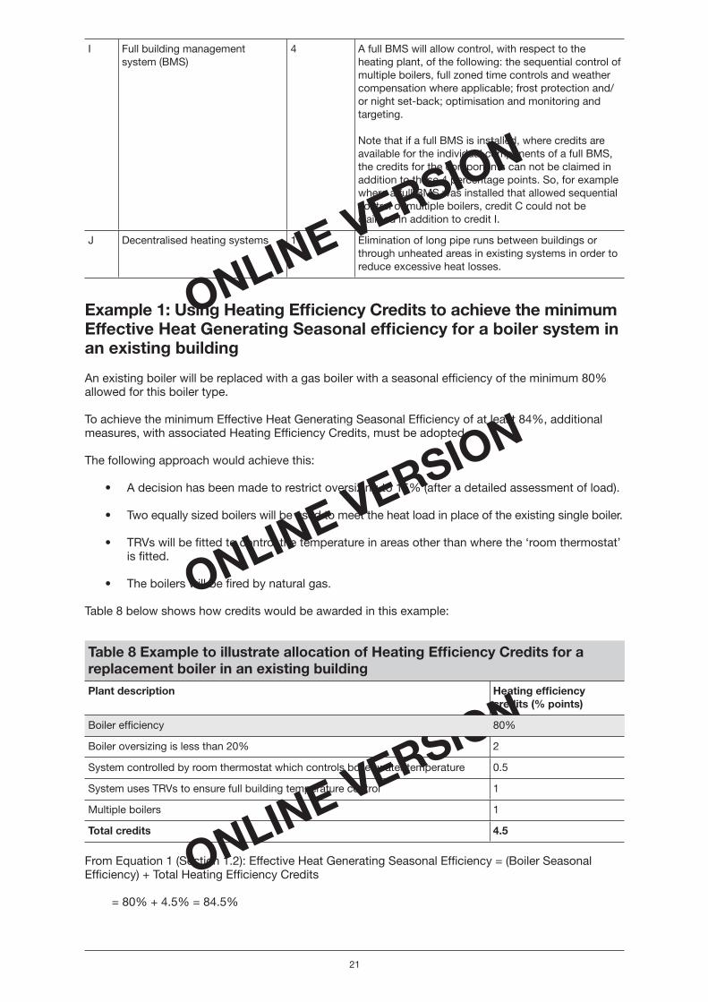
I Full building managementsystem (BMS)
4 A full BMS will allow control, with respect to the heating plant, of the following: the sequential control of multiple boilers, full zoned time controls and weather compensation where applicable; frost protection and/or night set-back; optimisation and monitoring and targeting.
Note that if a full BMS is installed, where credits are available for the individual components of a full BMS, the credits for the components can not be claimed in addition to these 4 percentage points. So, for example where a full BMS was installed that allowed sequential control of multiple boilers, credit C could not be claimed in addition to credit I.
J Decentralised heating systems 1 Elimination of long pipe runs between buildings or through unheated areas in existing systems in order to reduce excessive heat losses.
Example 1: Using Heating Effi ciency Credits to achieve the minimumEffective Heat Generating Seasonal effi ciency for a boiler system in an existing building
An existing boiler will be replaced with a gas boiler with a seasonal effi ciency of the minimum 80% allowed for this boiler type.
To achieve the minimum Effective Heat Generating Seasonal Effi ciency of at least 84%, additional measures, with associated Heating Effi ciency Credits, must be adopted.
The following approach would achieve this:
• A decision has been made to restrict oversizing to 15% (after a detailed assessment of load).
• Two equally sized boilers will be used to meet the heat load in place of the existing single boiler.
• TRVs will be fi tted to control the temperature in areas other than where the ‘room thermostat’ is fi tted.
• The boilers will be fi red by natural gas.
Table 8 below shows how credits would be awarded in this example:
Table 8 Example to illustrate allocation of Heating Effi ciency Credits for a replacement boiler in an existing buildingPlant description Heating effi ciency
credits (% points)
Boiler effi ciency 80%
Boiler oversizing is less than 20% 2
System controlled by room thermostat which controls boiler water temperature 0.5
System uses TRVs to ensure full building temperature control 1
Multiple boilers 1
Total credits 4.5
From Equation 1 (Section 1.2): Effective Heat Generating Seasonal Effi ciency = (Boiler Seasonal Effi ciency) + Total Heating Effi ciency Credits
= 80% + 4.5% = 84.5%
Non_domestic Heating.indd 21Non_domestic Heating.indd 21 17/5/06 16:07:0217/5/06 16:07:02
ONLINE VERSION
ONLINE VERSION
ONLINE VERSION
22
In this example the minimum requirement of an effective heat-generating seasonal effi ciency of 84% is exceeded by 0.5%.
2.7 Glossary of boiler terminology
Condensing boilers
Condensing boilers offer higher energy effi ciencies by recovering heat from the fl ue gases. This is achieved by increasing the heat exchanger surface area which recovers extra sensible heat whenever the boiler fi res. They become even more effi cient when system water temperatures are low because the extra heat exchanger promotes condensation, allowing much of the latent heat to be recaptured. Standing losses (when the boiler is not fi ring) are low and part load performance is very good. In multiple-boiler systems condensing boilers can be used as the lead boiler.
Standard boiler
In the context of this document, a standard boiler denotes a boiler that is non-condensing.
Zone control
Rooms or areas within buildings may need to be heated to different temperatures and/or at different times, each requiring independent control. Where several rooms or areas of a building behave in a similar manner, they can be grouped together as a ‘zone’ and put on the same circuit and controller.
Sequence control
This enables two or more heating boilers to be controlled in order to achieve the desired heat output temperature. This maximises the effi ciency of the boilers by switching them off in sequence when the heating load declines. This reduces fuel consumption as well as wear and tear on the boilers.
Direct acting weather compensation
These controls enable a condensing boiler to work at its optimum effi ciency. The controls allowthe boiler to vary its operating fl ow temperature automatically, to suit weather conditions and the temperatures inside the building. Weather compensation relies on communication between an external sensor and one inside the boiler. The boiler’s water fl ow temperature is varied accordingly, rather than the boiler turning on and off which wastes energy.
Weather compensation via a mixing valve
Similar to ‘Direct acting weather compensation’ except that the temperature of water supplied to the heat emitters is controlled by mixing the boiler fl ow and return instead of by altering the boiler temperature.
Optimiser
A control system employing an optimum start algorithm.
Optimum start
A control system or algorithm which starts plant operation at the latest time possible to achieve specifi ed conditions at the start of the occupancy period.
Optimum stop
A control system or algorithm which stops plant operation at the earliest possible time such that internal conditions will not deteriorate beyond preset limits by the end of the occupancy period.
Two-stage burner control – two-stage burner control enables two distinct fi ring rates.
Non_domestic Heating.indd 22Non_domestic Heating.indd 22 17/5/06 16:07:0217/5/06 16:07:02

ONLINE VERSION
ONLINE VERSION
ONLINE VERSION
23
Multi-stage burner control – multi-stage burner control will allow more than two distinct fi ring rates but without continuous adjustment between fi ring rates.
Modulating burner control – having continuous adjustment between fi ring rates. Modulating burner control will alter the fi ring rate to match the boiler load over the whole turndown ratio.
Decentralisation
The replacement of centralised boiler plant and its associated distribution pipework with several smaller, more accurately sized boiler plants, installed within or adjacent to the buildings or systems they serve. This enables elimination of long pipe runs between buildings or through unheated areas in existing systems in order to reduce excessive heat losses.
Building Management System (BMS)
A building wide network which allows communication with and control of items of HVAC plant (and other building systems) from a single remote control centre.
Full Building Management System
A full Building Management System will include, with respect to the heating plant, the sequential control of multiple boilers, full zone controls and compensation where applicable; frost protect and/or night set-back; optimisation and monitoring and targeting.
Non_domestic Heating.indd 23Non_domestic Heating.indd 23 17/5/06 16:07:0217/5/06 16:07:02
ONLINE VERSION
ONLINE VERSION
ONLINE VERSION
24
Section 3 Heat pumps
3.1 Introduction
This section outlines the minimum provisions needed to comply with Part L when space heating in new build and in existing buildings is provided by heating-only heat pumps or reverse cycle heat pumps.
It addresses the relevant heat pump types and measures, such as controls, for which the associated energy effi ciency benefi ts may be added to the Heat Generator Seasonal Effi ciency. For these purposesa heat pump is a device which takes heat energy from a low temperature source and upgrades it to a higher temperature at which it can be usefully employed for heating.
For guidance on heat pumps that also provide cooling see Section 9 of this guide.
3.2 Scope of the guidance
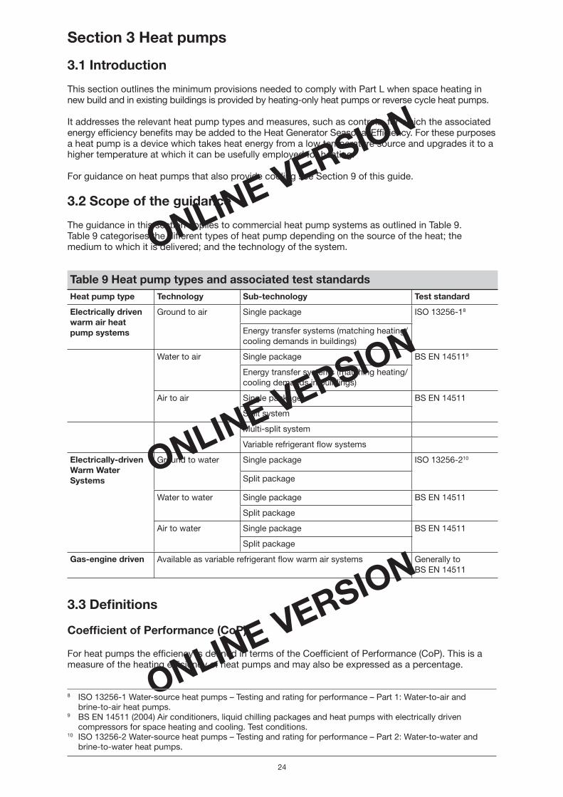
The guidance in this section applies to commercial heat pump systems as outlined in Table 9. Table 9 categorises the different types of heat pump depending on the source of the heat; the medium to which it is delivered; and the technology of the system.
Table 9 Heat pump types and associated test standards Heat pump type Technology Sub-technology Test standard
Electrically driven warm air heatpump systems
Ground to air Single package ISO 13256-18
Energy transfer systems (matching heating/cooling demands in buildings)
Water to air Single package BS EN 145119
Energy transfer systems (matching heating/cooling demands in buildings)
Air to air Single package BS EN 14511
Split system
Multi-split system
Variable refrigerant fl ow systems
Electrically-driven Warm Water Systems
Ground to water Single package ISO 13256-210
Split package
Water to water Single package BS EN 14511
Split package
Air to water Single package BS EN 14511
Split package
Gas-engine driven Available as variable refrigerant fl ow warm air systems Generally to BS EN 14511
3.3 Defi nitions
Coeffi cient of Performance (CoP)
For heat pumps the effi ciency is defi ned in terms of the Coeffi cient of Performance (CoP). This is a measure of the heating effi ciency of heat pumps and may also be expressed as a percentage.
8 ISO 13256-1 Water-source heat pumps – Testing and rating for performance – Part 1: Water-to-air andbrine-to-air heat pumps.
9 BS EN 14511 (2004) Air conditioners, liquid chilling packages and heat pumps with electrically driven compressors for space heating and cooling. Test conditions.
10 ISO 13256-2 Water-source heat pumps – Testing and rating for performance – Part 2: Water-to-water and brine-to-water heat pumps.
Non_domestic Heating.indd 24Non_domestic Heating.indd 24 17/5/06 16:07:0317/5/06 16:07:03

ONLINE VERSION
ONLINE VERSION
ONLINE VERSION
25
The heating CoP for a heat pump is the heat output of the heat pump divided by its power input as in Equation 4.
Heating CoP (%) = (Heat output/power input) x 100 Equation 4
In order to calculate the CoP the heat pump should be tested in line with the relevant standard for the technology in Table 9. The input power items that should be incorporated in this calculation are defi ned in the relevant test standard.
3.4 Minimum provisions for heat pumps in new and existing buildings
In order to comply with ADL2A and ADL2B, for heat pump systems in new and existing buildings,the following minimum provisions should be met:
a. The heat pump system should achieve a minimum Coeffi cient of Performance (Heat GeneratorSeasonal Effi ciency) no worse than the applicable value in Table 10;
AND
b. A minimum controls package should be adopted as detailed in Table 11.
There are currently no test standards in the EU for part load testing of heat pumps so a single minimum fi gure should be used that must be achieved at the heating system design conditions.
Table 10 Required minimum CoPs (Heat Generator Effi ciencies) for heat pumps systems in new and existing buildingsHeat pump type Heating CoP Heat Generator Effi ciency (%)
All types (except absorption heat pumps and gas-engine heat pumps)
2.0 (200%) when operating at the design conditions
Absorption heat pumps 0.5 (50%) when operating at the design conditions
Gas-engine heat pumps 1.0 (100%) when operating at the design conditions
The minimum provisions for controls given in Table 11 should be provided. Heating effi ciency credits are not available for these control measures.
Table 11 Minimum controls package for heat pump systems in new and existing buildings Heat source/sink
Technology Minimum controls package
Minimum controls package
All types All technologies A On/off zone control. If the unit serves a single zone,and for buildings with a fl oor area of 150m2 or less,the minimum requirement is achieved by default
Time control
Air to air Single package B Controls package A above PLUS
Heat pump unit controls to include:Control of room air temperature (if not provided externally)Control of outdoor fan operationDefrost control of external airside heat exchangerControl for secondary heating (if fi tted)
External controls should include:Room thermostat (if not provided internal to the HP) to regulate the space temperature and interlocked with the heat pump unit operation
Non_domestic Heating.indd 25Non_domestic Heating.indd 25 17/5/06 16:07:0317/5/06 16:07:03

ONLINE VERSION
ONLINE VERSION
ONLINE VERSION
26
Split system
Multi-split system
Variable refrigerantfl ow system
B Controls package A above PLUS
Heat pump unit controls to include:Control of room air temperature (if not provided externally).Control of outdoor fan operationDefrost control of external airside heat exchangerControl for secondary heating (if fi tted)
External controls should include:Room thermostat (if not provided internal to the HP) to regulate the space temperature and interlocked with the heat pump unit operation
Water orground to air
Single packageenergy transfer systems (matching heating/cooling demand in buildings)
D Controls package A above PLUS
Heat pump unit controls to include:Control of room air temperature (if not provided externally)Control of outdoor fan operation for cooling tower or dry cooler (energy transfer systems)Control for secondary heating (if fi tted) on air to air systemsControl of external water pump operation
External controls should include:Room thermostat (if not provided internal to the HP) to regulate the space temperature and interlocked with the heat pump system operation
Air to water
Water orground to water
Single package
Split package
E Controls package A above PLUS
Heat pump unit controls to include:Control of water pump operation (internal and external as appropriate)Control of water temperature for the distribution systemControl of outdoor fan operation for air to water unitsDefrost control of external airside heat exchanger for air to water systems
External controls should include:Room thermostat to regulate the space temperature and interlocked with the HP unit operation
Gas engine driven heat pumps are currently availableas variable refrigerantfl ow warmair systems
Multi-split
Variable refrigerant fl ow
F Controls package A above PLUS
Heat pump unit controls to include:Control of room air temperature (if not provided externally)Control of outdoor fan operationDefrost control of external airside heat exchangerControl for secondary heating (if fi tted)
External controls should include:Room thermostat (if not provided internal to the HP) to regulate the space temperature and interlocked with the heat pump unit operation
If further measures are taken beyond these minimum provisions for controls, in order to exceed the minimum CoP for the proposed system, then the credits indicated in Table 12 can be added. This modifi ed CoP (i.e. effective CoP) is entered in the accredited NCM tool when calculating the energy performance rating.
Non_domestic Heating.indd 26Non_domestic Heating.indd 26 17/5/06 16:07:0317/5/06 16:07:03

ONLINE VERSION
ONLINE VERSION
ONLINE VERSION
27
3.5 Heating Effi ciency Credits for heat pump systems
Heating Effi ciency Credits are available for measures over and above the minimum requirements which can be added to the CoP. The effi ciency measures outlined in Table 10 are not required,but where they are adopted the relevant effi ciency credit (percentage points) can be added to the minimum CoP (or to the manufacturer’s rating, where this exceeds the minimum COP) in order to calculate the Effective CoP.
In line with Equation 1 (Section 1.2): Effective CoP =Coeffi cient of performance (%) + Total Heating Effi ciency Credits
Table 12 Heating effi ciency credits for measures applicable to heat pump systems in new and existing buildingsMeasure Heating effi ciency credit Comments/defi nition
Ratio (% points)
<20% oversizing
0.02 2 The amount by which the maximum heat pump output exceeds heat output of the system at design conditions, expressed as a percentage of the system heat output
Optimised stop
0.02 2 A control system which stops plant operation at the earliest possible time such that internal conditions will not deteriorate beyond preset limits by the end of the occupancy period
Full zone control
0.02 2 Allowing each zone to operate independently in terms of start/stop time. Only applicable where operational conditions change in different zones
M & T system
0.02 2 Means of identifying changes in operation or onset of faults
Example 2: Using Heating Effi ciency Credits to exceed the minimum CoP for a heat pump installation
The following example illustrates how Heating Effi ciency Credits can be added to the effi ciency of a heat pump system to exceed the minimum provisions.
The proposed building will have an air-to-water, electrically driven heat pump to be used with an underfl oor heating system. When tested to EN 14511 the CoP was measured as 2.0 (200%) which meets the minimum provisions for this type of system.
The minimum controls package will be installed, that is:
• controls package A (zone control, demand control and time control) PLUS
• controls package B:
– control of water pump operation and water temperature for the distribution system
– control of outdoor fan operation for air to water units
– defrost control of external airside heat exchanger for air to water systems
– a room thermostat to regulate the space temperature and interlocked with the HPunit operation
Non_domestic Heating.indd 27Non_domestic Heating.indd 27 17/5/06 16:07:0417/5/06 16:07:04

ONLINE VERSION
ONLINE VERSION
ONLINE VERSION
28
In addition to the minimum controls package, optimised stop control and full zone control will be installed.
Table 13 shows how credits would be awarded to this example.
Table 13 Example to illustrate the allocation of Heating Effi ciency Credits to a new heat pump systemMeasure Heat Plant Effi ciency Credit (expressed as a ratio)
CoP single duct air-to-water heat pump 2.0 in this example (manufacturer’s rating)
Measures specifi ed in controls package A 0 (as minimum requirement)
Measures specifi ed in controls package B 0 (as minimum requirement)
Optimised stop 0.02
Full zone control 0.02
Total credits 0.04
In line with Equation 1 (Section 1.2) Effective CoP = (CoP) + (Total Heating Effi ciency Credits) = 2.0 + 0.04 = 2.04
The Effective CoP would therefore be 2.04, exceeding the minimum CoP. The value that would be entered in the accredited NCM tool to calculate an energy performance rating is 2.04.
Non_domestic Heating.indd 28Non_domestic Heating.indd 28 17/5/06 16:07:0417/5/06 16:07:04

ONLINE VERSION
ONLINE VERSION
ONLINE VERSION
29
Recommended good practice for heat pumps
Table 14 outlines further recommendations for heat pumps. It should be noted that these are not required for compliance with the Approved Documents ADL2A or ADL2B but are recommended as good practice.
Table 14 Recommended good practice for heat pumpsHeat source/sink Technology Comments
Air to air Single package Units may be ducted on one or other of the supply and return air sides or ducted on both sides. Ducting needs to be designed totake into account the maximum specifi c fan power allowable (see Section 10 of this guide) and to maintain the minimum allowable Coeffi cient of Performance
Split system
Multi-split system
Variable refrigerant fl ow system
Gas engine driven
A split system will comprise a single outdoor unit and a single indoor unit as a package. Multi-split and VRF systems will comprise a single outdoor unit and two or more indoor units as a package. Several packages may be used to satisfy the requirements of the building
In order for effi ciencies to be maintained all connecting pipework must installed in accordance with manufacturer’s recommendations (diameter, length, insulation and riser height). Any ducting needs to be designed to take into account the maximum specifi c fan power allowable and to maintain the minimum allowable Coeffi cient of Performance
Water or groundto air
Single package
Energy transfer systems (matching heating/cooling demand in buildings)
Energy transfer systems generally consist of multiple water source heat pumps connected in parallel to a common closed water loop. They are installed to offset the simultaneous heating and cooling demand in a building due to the different loads present on the aspects of the building. Water circulation pumps for the closedloop need to be taken into consideration along with the fan power required for the cooling tower or dry cooler or energy for water pumps for the ground loop if this method is utilised for heat injection and rejection. Any ducting needs to be designed to take into account the maximum specifi c fan power allowable and to maintain the minimum allowable Coeffi cient of Performance
Air to water
Water to groundor water
Single package
Split package
Water circulation pumps for the delivery of heated water to the building need to be taken into consideration in the calculation. Additionally the energy of water pumps used for the heat source (water or ground) needs to be considered in the calculation. Any ducting needs to be designed to take into account the maximum specifi c fan power allowable and to maintain the minimum allowable Coeffi cient of Performance
Non_domestic Heating.indd 29Non_domestic Heating.indd 29 17/5/06 16:07:0517/5/06 16:07:05

ONLINE VERSION
ONLINE VERSION
ONLINE VERSION
30
Section 4 Gas and oil-fi red warm air heaters
4.1 Introduction
This section outlines the minimum provisions needed to comply with Part L when space heating in new build and in existing buildings is provided by warm air heaters. It addresses the relevant types of warm air heaters and measures, such as controls, for which the associated energy effi ciency benefi ts may be added to the Heat Generator Seasonal Effi ciency.
Note that it is advisable to use the National Calculation Methodology (NCM) to determine the carbon performance of the proposed new building as some of the benefi ts of using warm air heaters are included in the calculation procedure.
4.2 Scope of the guidance
The guidance given in this section covers the types of warm air heater systems described in Table 15. The provisions of this section also cover indirect gas or oil-fi red heat exchangers (as used in large ducted systems for offi ce blocks, shopping and leisure complexes, etc.) to provide heating and fresh or conditioned air. Warm air central heating systems are not within the scope of this section.
Table 15 Warm air heaters and associated test methodologies Type of warm air heater Product standard
Type 1 Gas-fi red forced convection without a fan to assist transportation of combustion air and/or combustion products
BS EN 621:199811
Type 2 Gas-fi red forced convection incorporating a fan to assist transportation of combustion air and/or combustion products
BS EN 1020:199812
Type 3 Direct gas-fi red forced convection BS EN 525:199813
Type 4 Oil-fi red forced convection BS EN 13842:200414
4.3 Defi nitions
Heat Generator Seasonal Effi ciency
As air heaters operate under the same conditions at all times their Heat Generator Seasonal Effi ciencyis equivalent to their measured steady state thermal effi ciency (gross calorifi c value). Gross thermal effi ciency will be obtained from the heater manufacturer’s data. If the net effi ciency is given this must be converted to a gross effi ciency, using the conversion factors in Appendix 1 of this guide.
For indirect-fi red heaters data values for net heat input and output are measured using the effi ciency test methods described in EN 1020, EN 621 or EN 13824 as appropriate.
For direct-fi red heaters the effi ciency should be calculated using the method described in EN 525.
The calculation of the gross thermal effi ciency should:
• Include the heater.
• Include associated products of combustion exhaust chimney within the building envelope.
• Exclude fans.
11 BS EN 621:1998 Non domestic gas fi red forced convection air heaters for space heating not exceeding a net heat input of 300kW, without a fan to assist transportation of combustion air. ISBN 0 580 295834.
12 BS EN 1020:1998 Non domestic gas-fi red convection air heaters for space heating not exceeding a net heat input of 300kW, incorporating a fan to assist transportation of combustion air and/or combustion products (AMD 13525).
13 BS EN 525:1998 Non domestic direct gas-fi red forced convection air heaters for space heating not exceeding a net input of 300kW.
14 BS EN 13842:2004 Oil-fi red convection air heaters – stationary and transportable for space heating.
Non_domestic Heating.indd 30Non_domestic Heating.indd 30 17/5/06 16:07:0517/5/06 16:07:05

ONLINE VERSION
ONLINE VERSION
ONLINE VERSION
31
4.4 Minimum provisions for warm air heaters in new andexisting buildings
In order to comply with ADL2A and ADL2B, for warm air systems in new and existing buildings, the following minimum provisions should be met:
a. The warm air system should achieve a minimum thermal effi ciency (gross calorifi c value) (Heat Generator Effi ciency) no worse than the applicable value in Table 16;
AND
b. A minimum controls package should be adopted entailing time control AND space temperature control AND, for buildings with a fl oor area greater than 150m2, zone control.
Table 16 Minimum thermal effi ciencies for warm air heatersWarm air heater type (as defi ned in Table 15) Minimum thermal effi ciency (gross calorifi c value)
Types 1, 2 and 4 80%
Type 3* 90%
*Note. For Type 3 air heaters 100% of the net heat input is delivered to the space. Specifi c ventilation requirements as defi ned in EN 525 must be met.
4.5 Heating Effi ciency Credits for warm air heaters in new and existing buildings
Heating Effi ciency Credits are available for measures listed in Table 17; however, these measures are optional. If these measures are adopted, the associated effi ciency benefi ts can be added to the Heat Generating Seasonal Effi ciency and inputted into the accredited NCM tool in order to improve the energy performance rating for the proposed building.
Therefore, when demonstrating compliance for new buildings the relevant effi ciency value to input intothe accredited NCM model is the applicable thermal effi ciency value in Table 16 (or the manufacturer’srating for the appliance being specifi ed, where it exceeds the relevant value in Table 16) plus any Heating Effi ciency Credits.
Note that Heating Effi ciency Credits are not available for the minimum controls package.
Table 17 Heating Effi ciency Credits for measures applicable to warmair heaters Measure Heating Effi ciency
Credits (% points)Comments/defi nition
Optimised shut down 1 A control system which stops plant operation at the earliest possible time such that internal conditions will not deteriorate beyond preset limits by the end of the occupancy period
Hi/lo burners 2 Two stage burners which enable two distinct fi ring rates
Modulating burners 3 Burner controls allow continuous adjustment between fi ring rates
Destratifi cation fans and air-induction schemes
It is recognised that destratifi cation fans and air-induction schemes may improve the effi ciency of a warm air system and signifi cantly reduce the carbon emissions associated with the heating system. The benefi ts associated with these measures are calculated in the accredited NCM tool. Note that warm air systems with air induction schemes or destratifi cation fans should not be confused with central heating with air distribution. (Warm air central heating systems are not within the scope of the Non-domestic Heating, Cooling and Ventilation Compliance Guide.)
Non_domestic Heating.indd 31Non_domestic Heating.indd 31 17/5/06 16:07:0517/5/06 16:07:05

ONLINE VERSION
ONLINE VERSION
ONLINE VERSION
32
Example 3: Using Heating Effi ciency Credits to exceed the minimum Heat Generator Seasonal Effi ciency for a warm air heater
The following example illustrates how Heating Effi ciency Credits can be used to exceed the minimum Heat Generator Seasonal Effi ciency for a warm air heater system.
The proposed building will have a gas-fi red forced convection warm air heater without a fan to assist transportation of combustion air and/or combustion products. When tested to BS EN 621:1998 the effi ciency is calculated as 80% which meets the minimum Heat Generator Effi ciency requirement for this type of system.
The minimum controls package will be installed, i.e. zone, space temperature and time controls.In addition to the minimum controls requirement, optimised start/stop and modulating burners willbe provided.
Table 18 shows how credits would be awarded in this example.
Table 18 Example to illustrate the allocation of Heating Effi ciency Credits to a warm air heater systemMeasure Heating effi ciency credits (% points)
Thermal effi ciency of warm air heater 80%
Zone, space and temperature controls 0 (as minimum requirement)
Modulating burners 3
Optimised shut down 1
Total credits 4
From Equation 1 (Section 1.2): Effective Heat Generating Seasonal Effi ciency = Gross Thermal Effi ciency + Total Heating Effi ciency Credits
= 80% + 4% = 84%
Destratifi cation fans will be also be installed providing seven volume changes per hour. But note that the effi ciency benefi ts of the destratifi cation measures are calculated in the accredited NCM tool.
The Effective Heat Generating Seasonal Effi ciency would therefore be 84%, exceeding the minimum requirement by four percentage points. The value that would be entered in the accredited NCM tool to calculate an energy performance rating is 84%, expressed as a ratio (i.e. 0.84).
Non_domestic Heating.indd 32Non_domestic Heating.indd 32 17/5/06 16:07:0617/5/06 16:07:06

ONLINE VERSION
ONLINE VERSION
ONLINE VERSION
33
Section 5 Gas and oil-fi red radiant technology
5.1 Introduction
This section outlines the minimum provisions needed to comply with Part L when space heating in new build and in existing buildings is provided by radiant heaters. It addresses the relevant radiant heater types and measures, such as controls, for which the associated energy effi ciency benefi ts may be added to the Heat Generator Seasonal Effi ciency.
Note that it is advisable to use the NCM to determine the carbon performance of the proposed new building as some of the benefi ts of using radiant heaters are included in the calculation procedure.
5.2 Scope of the guidance
The guidance given in this section covers the types of radiant heater systems outlined in Table 19 below:
Table 19 Types of radiant heater and associated product standards Radiant heater type Product standard
Luminous radiant heater BS EN 419:200015
Non-luminous radiant heater BS EN 416-1:199916
Multi-burner radiant heaters BS EN 777 series17
Oil-fi red radiant heaters N/A
5.3 Defi nitions
Radiant Heater Seasonal Effi ciency
For radiant heaters the Heat Generator Seasonal Effi ciency is equivalent to its thermal effi ciency (gross calorifi c value).
For fl ued appliances the thermal effi ciency of the radiant heater will be stated by the manufacturer of the radiant heater having been measured according to the test standards EN 102018 or EN 1384219 as applicable. The procedures in EN 1020 and EN 13842 yield a net effi ciency – this must be converted to a gross effi ciency, using the conversion factors in Appendix 1 of this guide.
The calculation of the thermal effi ciency (gross calorifi c value) should:
• Include the radiant heater.
• Include associated fl ue pipe/tailpipe within the building envelope.
• Exclude fans.
For unfl ued heaters the minimum thermal effi ciency levels given in Table 20 should be used.
15 BS EN 419-1:2000 Non-domestic gas-fi red overhead luminous radiant heaters. Safety.16 BS EN 416-1:1999 Single burner gas-fi red overhead radiant-tube heaters. Safety.17 BS EN 777-1:1999 Multi-burner gas-fi red overhead radiant tube heater systems for non-domestic use.
System D, safety. BS EN 777-2:1999 Multi-burner gas-fi red overhead radiant tube heater systems for non-domestic use.
System E, safety. BS EN 777-3:2000 Multi-burner gas-fi red overhead radiant tube heater systems for non-domestic use.
System F, safety. BS EN 777-4:1999 Multi-burner gas-fi red overhead radiant tube heater systems for non-domestic use.
System H, safety.18 BS EN 1020 Non domestic gas-fi red convection air heaters for space heating not exceeding a net heat input of
300kW, incorporating a fan to assist transportation of combustion air and/or combustion products (AMD 13525). BS EN 13842:2004 Oil-fi red convection air heaters – stationary and transportable for space heating.19 BS EN 13842:2004 Oil-fi red convection air heaters – stationary and transportable for space heating.
Non_domestic Heating.indd 33Non_domestic Heating.indd 33 17/5/06 16:07:0617/5/06 16:07:06

ONLINE VERSION
ONLINE VERSION
ONLINE VERSION
34
5.4 Minimum provisions for radiant heaters
In order to comply with ADL2A and ADL2B, for radiant heaters in new and existing buildings, the following minimum provisions should be met:
a. The radiant heater system should achieve a minimum Heat Generator Seasonal Effi ciency, that is a thermal effi ciency (gross calorifi c value), of no less than the relevant value in Table 20;
AND
b. A minimum controls package should be adopted entailing time control and space temperaturecontrol with black bulb sensors.
Table 20 Minimum thermal effi ciency levels (Heat Generator Seasonal Effi ciency) for radiant heater technology Appliance type Minimum thermal effi ciency (gross calorifi c value) %
Luminous radiant heater (unfl ued) 85.5
Non-luminous radiant heater (unfl ued) 85.5
Non-luminous radiant heater (fl ued) 73.8
Multi-burner radiant heaters 80
5.5 Heating Effi ciency Credits for radiant heaters in new andexisting buildings
Heating Effi ciency Credits are available for measures listed in Table 21; however, these measures are optional. If these measures are adopted, the associated effi ciency benefi ts can be added to the Heat Generating Seasonal Effi ciency and input into the accredited NCM tool in order to improve the energy performance rating for the proposed building.
Therefore, when demonstrating compliance for new buildings the relevant effi ciency value to input intothe accredited NCM model is the applicable thermal effi ciency value in Table 20 (or the manufacturer’srating for the appliance being specifi ed, where it exceeds the relevant value in Table 20) plus any Heating Effi ciency Credits.
Note that Heating Effi ciency Credits are not available for the minimum controls package
It is recognised that the effi ciency of a heating system using radiant heaters improves with increasing room height. These effi ciency benefi ts arise from a reduction in the ventilation and fabric losses. The effi ciency benefi ts are assigned in the accredited NCM tool.
Table 21 Heating Effi ciency Credits for measures applicable to radiant heatersMeasure Heating Effi ciency
Credits % pointsComments/defi nition
Controls (additional to the minimum package)
Optimisedshut down
1 A control system which stops plant operationat the earliest possible time such that internal conditions will not deteriorate beyond preset limits by the end of the occupancy period
Zone control 1 Allowing each zone to operate independently in terms of start/stop time. Only applicable where operational conditions change in different zones
Non_domestic Heating.indd 34Non_domestic Heating.indd 34 17/5/06 16:07:0617/5/06 16:07:06
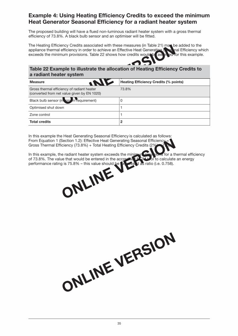
ONLINE VERSION
ONLINE VERSION
ONLINE VERSION
35
Example 4: Using Heating Effi ciency Credits to exceed the minimum Heat Generator Seasonal Effi ciency for a radiant heater system
The proposed building will have a fl ued non-luminous radiant heater system with a gross thermal effi ciency of 73.8%. A black bulb sensor and an optimiser will be fi tted.
The Heating Effi ciency Credits associated with these measures (in Table 21) may be added to the appliance thermal effi ciency in order to achieve an Effective Heat Generating Seasonal Effi ciency whichexceeds the minimum provisions. Table 22 shows how credits would be awarded for this example.
Table 22 Example to illustrate the allocation of Heating Effi ciency Credits toa radiant heater systemMeasure Heating Effi ciency Credits (% points)
Gross thermal effi ciency of radiant heater(converted from net value given by EN 1020)
73.8%
Black bulb sensor (minimum requirement) 0
Optimised shut down 1
Zone control 1
Total credits 2
In this example the Heat Generating Seasonal Effi ciency is calculated as follows:From Equation 1 (Section 1.2): Effective Heat Generating Seasonal Effi ciency =Gross Thermal Effi ciency (73.8%) + Total Heating Effi ciency Credits (2%) = 75.8%
In this example, the radiant heater system exceeds the minimum provisions for a thermal effi ciencyof 73.8%. The value that would be entered in the accredited NCM tool to calculate an energy performance rating is 75.8% – this value should be expressed as ratio (i.e. 0.758).
Non_domestic Heating.indd 35Non_domestic Heating.indd 35 17/5/06 16:07:0717/5/06 16:07:07

ONLINE VERSION
ONLINE VERSION
ONLINE VERSION
36
Section 6 Combined Heat and Power (CHP) andcommunity heating
6.1 Introduction
This section outlines the minimum provisions needed to comply with Part L when space heating in new build and in existing buildings is provided by Combined Heat and Power (CHP). It addresses the relevant CHP technologies and measures, such as controls, that may be used to improve the effi ciency of the heat generator.
CHP units are normally used in conjunction with boilers. The majority of the annual heat demand is usually supplied from the CHP plant and the boilers are used to meet peak demands and for periods when the CHP unit is not operating either for economic considerations, for example at night, or during maintenance downtime. CHP units may on a relatively small scale supply single buildings or, on a larger scale, supply a number of buildings through a Community Heating system. The most common fuel is natural gas which can be used in spark-ignition gas engines, micro-turbines, or gas turbines in open cycle or combined cycle.
This section gives the minimum provisions for CHP units which may or may not supply community heating. Guidance on community heating systems (including those with heat generators other than CHP) is available in the Domestic Heating Compliance Guide published by the OPDM in support of Part L of the Building Regulations.
6.2 Scope of the guidance
The guidance in this section covers all types of CHP systems used in commercial applications.
6.3 Defi nitions
Combined Heat and Power Quality Assurance (CHPQA)
CHPQA20 is a scheme under which registration and certifi cation of CHP schemes is carried out in accordance with the criterion for Good Quality CHP.
CHPQA Quality Index (CHP(QI))
This is an indicator of the energy effi ciency and environmental performance of a CHP scheme, relative to the generation of the same amounts of heat and power by separate, alternative means.
6.4 Minimum provisions for CHP in new and existing buildings
In order to comply with ADL2A and ADL2B, for CHP units in new and existing buildings, the following minimum provisions should be met:
a. The CHP plant shall achieve a minimum CHPQA Quality Index of 105;
AND
b. As a minimum, the control system shall ensure that the CHP unit operates as the leadheat generator;
AND
c. Metering shall be provided to measure the hours run, the electricity generated and the fuel supplied to the CHP unit;
AND
d. For peak and standby boilers, the minimum boiler effi ciencies and minimum controls applyas in Section 2 of this guide.
20 Further information about the CHPQA programme is available on the website: www.chpqa.com
Non_domestic Heating.indd 36Non_domestic Heating.indd 36 17/5/06 16:07:0717/5/06 16:07:07

ONLINE VERSION
ONLINE VERSION
ONLINE VERSION
37
The CHP should be sized to supply no less than 45% of the annual total heating demand (i.e. space heating, domestic hot water heating and process heating) unless there are overriding practical or economic constraints.
Total CO2 emissions from CHP – data input for NCM tools (e.g. SBEM)
CHP may be used as the main or supplementary heat source in Community Heating or District Heating schemes. In calculating the total CO2 emissions for a new building to show compliance,the following data shall be entered into the accredited NCM tool (e.g. SBEM):
1. The proportion of the annual heat demand (H) supplied from the CHP plant (P). This is neededas the CHP unit is normally sized below the peak heat demand of the building and will also be outof service for maintenance purposes.
2. The overall effi ciency ratio of the CHP plant (E) as defi ned in Equation 5 and taking account of part load operation and all heat rejection predicted by an operating model.
Overall effi ciency E = annual useful heat supplied + annual electricity generated(net of parasitic electricity use) divided by the annual energy of the fuel supplied(in gross calorifi c value terms) Equation 5
3. The heat to power ratio of the CHP plant (R) is calculated for the annual operation according to Equation 6:
Heat to power ratio (R) = annual useful heat supplied divided by annual electricitygenerated (net of parasitic electricity use) Equation 6
From these parameters, the SBEM model (or other accredited NCM model) will calculate the CO2 emissions in the heat supplied from the CHP plant using an emissions factor for the electricity generated by the CHP of 568g/kWh applied to the annual total of electricity generation.
The annual CO2 emissions for the heat supplied by a CHP plant (assuming gas-fi red) is given by Equation 7:
Annual CO2 emissions for the heat supplied by a CHP plant = ((H x P)/E)+(H x P)/(R x E)) x 194 – ((H x P)/R) x 568 Equation 7
(CO2 emissions are in kg for the heat demand H in MWh)where the terms H, P, E and R are defi ned above.
The CO2 emissions for the balance of heat supplied by the boilers is then calculated by the SBEM model as for a boiler only system.
6.5 Additional guidance for community heating in new andexisting buildings
The design of the community heating (CH) connection and the building’s heating control system shall take account of the requirements of the CH Organisation with respect to maintaining low return temperatures at part load and limiting the maximum fl ow rate to be supplied by the CH system to the agreed level. A heat meter shall be installed to measure the heat energy supplied and to monitor themaximum heat demand, the maximum CH fl ow rate and the return temperatures onto the CH network.
Further guidance can be found in the following documents:
• Carbon Trust GPG 234 – Community Heating and CHP
• CIBSE AM12 – Small-scale CHP for buildings
At the time of writing, the guidance for micro-CHP is still under development and is expected to include:
• A Good Practice Guide specifying the minimum standards for installation and control of micro-CHP
• Publicly Available Specifi cation – PAS 67 Laboratory test to determine heating and electricalperformance of heat-led micro-cogeneration packages primarily intended for heating dwellings.
Non_domestic Heating.indd 37Non_domestic Heating.indd 37 17/5/06 16:07:0717/5/06 16:07:07

ONLINE VERSION
ONLINE VERSION
ONLINE VERSION
38
Section 7 Electric space heating
7.1 Introduction
This section outlines the minimum provisions needed to comply with Part L when space heating in new build and in existing buildings is provided by electric heaters. It addresses the relevant electric heater types and the minimum provision of controls.
7.2 Scope of the guidance
The guidance given in this section covers the following types of electric heating systems which may be used to provide primary or secondary space heating:
• Electric boilers
• Electric warm air systems (not including electric warm air central heating systems)
• Electric panel heaters
• Electric storage systems including integrated storage/direct systems
• Electric fan heaters and fan convector heaters
• Electric radiant heaters including quartz and ceramic types
The guidance does not cover electric heat pumps or portable electric heating devices.
7.3 Defi nitions
The electric heating devices in this section are assumed to be 100% thermally effi cient in conversion of electricity to heat within the building and therefore a Minimum Heat Generating Seasonal Effi ciency is not defi ned.
7.4 Minimum provisions for electric space heating in new andexisting buildings
In order to comply with ADL2A and ADL2B, for electric space heating systems in new and existing buildings, the following minimum provisions should be met:
a. Electric boilers should meet the minimum provisions for controls given in Table 23.
b. Electric space heating systems, other than boilers, should meet the minimum provisions for controls given in Table 24.
Non_domestic Heating.indd 38Non_domestic Heating.indd 38 17/5/06 16:07:0817/5/06 16:07:08
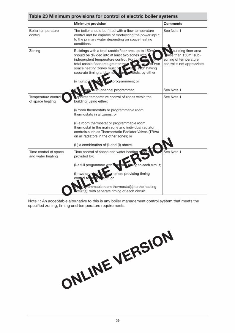
ONLINE VERSION
ONLINE VERSION
ONLINE VERSION
39
Table 23 Minimum provisions for control of electric boiler systems Minimum provision Comments
Boiler temperaturecontrol
The boiler should be fi tted with a fl ow temperature control and be capable of modulating the power input to the primary water depending on space heating conditions.
See Note 1
Zoning Buildings with a total usable fl oor area up to 150m2
should be divided into at least two zones with independent temperature control. For buildings with a total usable fl oor area greater than 150m2, at least two space heating zones must be provided, each having separate timing and temperature controls, by either:
(i) multiple heating zone programmers; or
(ii) a single multi-channel programmer.
If the building fl oor area is less than 150m2 sub-zoning of temperature control is not appropriate.
See Note 1
Temperature control of space heating
Separate temperature control of zones within the building, using either:
(i) room thermostats or programmable room thermostats in all zones; or
(ii) a room thermostat or programmable room thermostat in the main zone and individual radiator controls such as Thermostatic Radiator Valves (TRVs) on all radiators in the other zones; or
(iii) a combination of (i) and (ii) above.
See Note 1
Time control of space and water heating
Time control of space and water heating should be provided by:
(i) a full programmer with separate timing to each circuit;
(ii) two or more separate timers providing timing control to each circuit; or
(iii) programmable room thermostat(s) to the heating circuit(s), with separate timing of each circuit.
See Note 1
Note 1: An acceptable alternative to this is any boiler management control system that meets the specifi ed zoning, timing and temperature requirements.
Non_domestic Heating.indd 39Non_domestic Heating.indd 39 17/5/06 16:07:0817/5/06 16:07:08

ONLINE VERSION
ONLINE VERSION
ONLINE VERSION
40
Table 24 Minimum provisions for control of primary and secondary electric heating systems (other than electric boilers)Electric heating system
Requirement Reasonable provision Comments
Electric warm air systems
Time and temperature control, either integral to the heater or external
(i) A time switch/programmer and room stat OR
(ii) a programmable room thermostat
Zone control – for buildings with a total usable fl oor area greater than 150m2 more than one space heating circuit should be provided, each having separate timing and temperature controls
(i) Multiple heating zone programmers OR
(ii) a single multi-channel programmer
Electric radiant heaters
Zone or occupancy control Connection to a passive infrared detector
Electric radiant heaters can provide zone heating or be used for a full heating scheme. Common electric radiant heaters include the quartz or ceramic type
Panel/skirting heaters
Local time and temperature control
(i) Time control provided by a programmable time switch integrated into the appliance OR a separate time switch
(ii) Individual temperature control provided by integral thermostats OR by separate room thermostats
Panel heater systems provide instantaneous heat
Storage heaters Charge control Automatic control of input charge (ability to detect the internal temperature and adjust the charging of the heater accordingly)
Temperature control Manual controls for adjusting the rate of heat release from the appliance such as adjustable damper or some other thermostatically controlled means
Fan/fanconvector heaters
Local fan control A switch integrated into the appliance OR a separate remote switch
Individual temperature control Integral switches or separate remote switching
Non_domestic Heating.indd 40Non_domestic Heating.indd 40 17/5/06 16:07:0917/5/06 16:07:09
ONLINE VERSION
ONLINE VERSION
ONLINE VERSION
41
Section 8 Domestic hot water
8.1 Introduction
This section outlines the minimum provisions needed to comply with Part L when domestic hotwater systems are provided in new build and in existing buildings. It addresses the relevant hot water system types and measures, such as controls, for which the associated energy effi ciency benefi ts may be added to the Heat Generator Seasonal Effi ciency.
As well as Building Regulations, other regulations apply to the provision of domestic hot water systems and energy-saving measures should not compromise the safety of people or the ability of the system to achieve approved regimes for the control of legionella.
For guidance on solar hot water systems, refer to the Domestic Heating Compliance Guide which is published by NBS in support of Building Regulations Part L and the NBS publication Low or Zero Carbon Energy Sources – Strategic Guide.
8.2 Scope of the guidance
The guidance in this section covers conventional gas, electric and oil-fi red systems.
The minimum provisions of this section apply only to dedicated water heaters. Therefore, the effi ciency performance of central heating boilers which provide space heating and domestic hot water should be as in Section 2 of this guide.
Solar hot water systems are not within the scope of this guide; however, in the UK they are normally operated with a back-up source of heat, such as gas or electricity so the guidance in this section will apply to the back-up system.
The types of domestic hot water systems covered in this section are shown in Table 25.
Non_domestic Heating.indd 41Non_domestic Heating.indd 41 17/5/06 16:07:0917/5/06 16:07:09

ONLINE VERSION
ONLINE VERSION
ONLINE VERSION
42
Table 25 Types of hot water systems covered by the Non-domestic Heating, Cooling and Ventilation Compliance Guide DHW system type Defi nition
Indirect natural gas, LPG and oil-fi red systems
A system in which the water is supplied to the draw-off points from a device in which water is heated by means of an element through which the heating medium is circulated in such a manner that it does not mix with the hot water supply. In practice these are likely to be boilers dedicated to the supply of DHW and therefore would meet the minimum requirements of the Boiler Effi ciency Directive
Direct-fi red storage water heater system (natural gas, LPG and oil-fi red)
A system in which the water is supplied to the draw-off points from a hot water vessel in which water is heated by combustion gases from a primary energy source
Electric water heaters
Point of use electrically heated water heater systems
A system in which the water is supplied to the draw-off points from a device in which water is heated by an electric element or elements immersed in the stored water. The water heater is situated in close proximity to the draw-off points (point of use) and should have a storage capacity no greater than 100 litres
Instantaneous electrically heated water heater systems
A system in which the water is supplied to the draw-off points from a device in which the water is heated by an electric element or elements that heat the cold water as it fl ows through the water heater. The water heater is situated in close proximity to the draw-off points. The unit has no storage volume as water is instantaneously heated as it fl ows through the device
Local electrically heated water heater systems
A system in which the water is supplied to the draw-off points from a device in which water is heated by an electric element or elements immersed in the stored water. The water heater is situated in the locality of the draw-off points and should have a storage capacity of between 100 and 300 litres. Bulk heating of the water heater should be arranged to occur using off peak electricity supplies
Centralised electrically heated water heater systems
A system in which the water is supplied to the draw-off points from a device in which water is heated by an electric element or elements immersed in the stored water. The water heater is situated centrally with a distribution system to supply water to the draw-off points and should have a capacity greater than 300 litres. Bulk heating of the water heater should be arranged to occur using off peak electricity supplies
8.3 Defi nitions
The heat generator seasonal effi ciency is defi ned for each system type in Table 26.
The Effective Heat Generating Seasonal Effi ciency is the heat generator seasonal effi ciency plus heating effi ciency credits gained by adopting measures in Table 29.
Non_domestic Heating.indd 42Non_domestic Heating.indd 42 17/5/06 16:07:0917/5/06 16:07:09
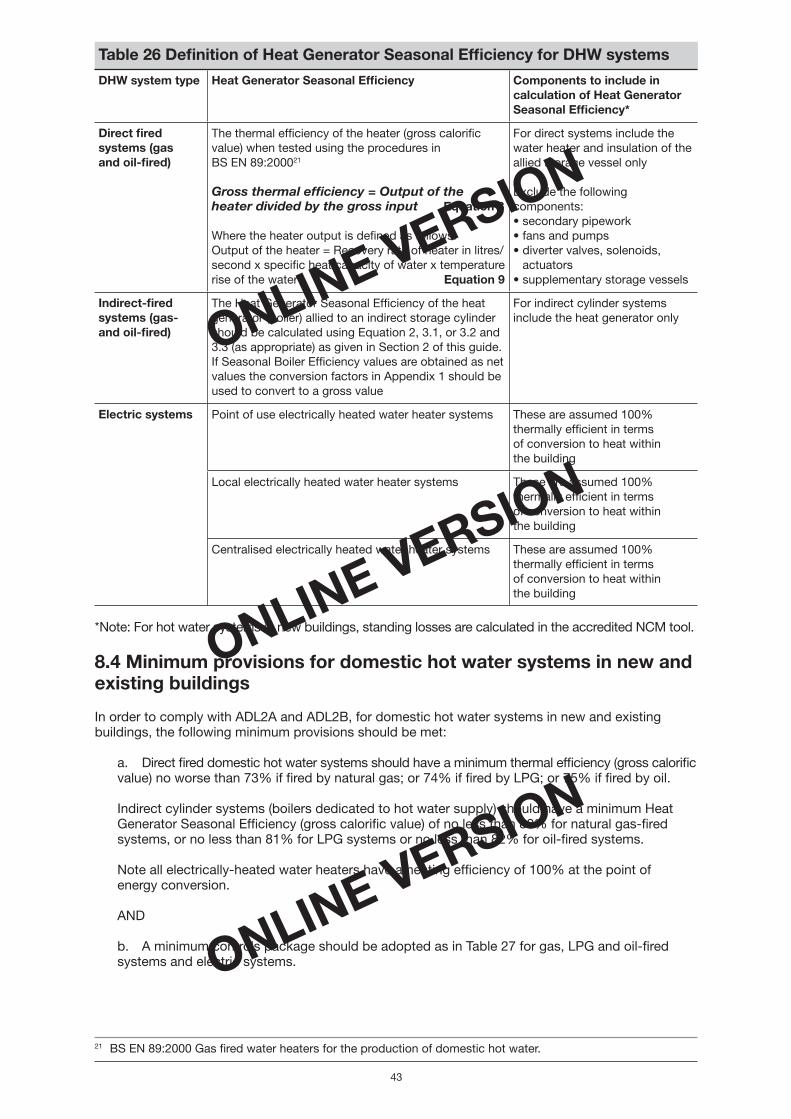
ONLINE VERSION
ONLINE VERSION
ONLINE VERSION
43
Table 26 Defi nition of Heat Generator Seasonal Effi ciency for DHW systems
DHW system type Heat Generator Seasonal Effi ciency Components to include in calculation of Heat Generator Seasonal Effi ciency*
Direct fi red systems (gasand oil-fi red)
The thermal effi ciency of the heater (gross calorifi c value) when tested using the procedures in BS EN 89:200021
Gross thermal effi ciency = Output of the heater divided by the gross input Equation 8
Where the heater output is defi ned as follows:Output of the heater = Recovery rate of heater in litres/second x specifi c heat capacity of water x temperature rise of the water Equation 9
For direct systems include the water heater and insulation of the allied storage vessel only
Exclude the following components: • secondary pipework• fans and pumps• diverter valves, solenoids,
actuators• supplementary storage vessels
Indirect-fi red systems (gas-and oil-fi red)
The Heat Generator Seasonal Effi ciency of the heat generator (boiler) allied to an indirect storage cylinder should be calculated using Equation 2, 3.1, or 3.2 and 3.3 (as appropriate) as given in Section 2 of this guide. If Seasonal Boiler Effi ciency values are obtained as net values the conversion factors in Appendix 1 should be used to convert to a gross value
For indirect cylinder systems include the heat generator only
Electric systems Point of use electrically heated water heater systems These are assumed 100% thermally effi cient in termsof conversion to heat withinthe building
Local electrically heated water heater systems These are assumed 100% thermally effi cient in termsof conversion to heat withinthe building
Centralised electrically heated water heater systems These are assumed 100% thermally effi cient in termsof conversion to heat withinthe building
*Note: For hot water systems in new buildings, standing losses are calculated in the accredited NCM tool.
8.4 Minimum provisions for domestic hot water systems in new and existing buildings
In order to comply with ADL2A and ADL2B, for domestic hot water systems in new and existing buildings, the following minimum provisions should be met:
a. Direct fi red domestic hot water systems should have a minimum thermal effi ciency (gross calorifi cvalue) no worse than 73% if fi red by natural gas; or 74% if fi red by LPG; or 75% if fi red by oil.
Indirect cylinder systems (boilers dedicated to hot water supply) should have a minimum Heat Generator Seasonal Effi ciency (gross calorifi c value) of no less than 80% for natural gas-fi red systems, or no less than 81% for LPG systems or no less than 82% for oil-fi red systems.
Note all electrically-heated water heaters have a heating effi ciency of 100% at the point ofenergy conversion.
AND
b. A minimum controls package should be adopted as in Table 27 for gas, LPG and oil-fi red systems and electric systems.
21 BS EN 89:2000 Gas fi red water heaters for the production of domestic hot water.
Non_domestic Heating.indd 43Non_domestic Heating.indd 43 17/5/06 16:07:1017/5/06 16:07:10
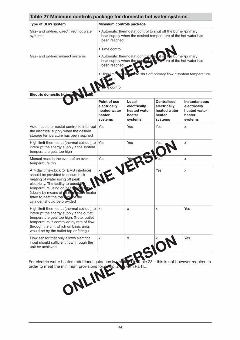
ONLINE VERSION
ONLINE VERSION
ONLINE VERSION
44
Table 27 Minimum controls package for domestic hot water systems Type of DHW system Minimum controls package
Gas- and oil-fi red direct fi red hot water systems
• Automatic thermostat control to shut off the burner/primaryheat supply when the desired temperature of the hot water has been reached
• Time control
Gas- and oil-fi red indirect systems • Automatic thermostat control to shut off the burner/primaryheat supply when the desired temperature of the hot water has been reached
• High limit thermostat to shut off primary fl ow if system temperature too high
• Time control
Electric domestic hot water systems
Point of use electrically heated water heater systems
Local electrically heated water heater systems
Centralised electrically heated water heater systems
Instantaneous electrically heated water heater systems
Automatic thermostat control to interrupt the electrical supply when the desired storage temperature has been reached
Yes Yes Yes x
High limit thermostat (thermal cut-out) to interrupt the energy supply if the system temperature gets too high
Yes Yes Yes x
Manual reset in the event of an over-temperature trip
Yes Yes Yes x
A 7-day time-clock (or BMS interface) should be provided to ensure bulk heating of water using off peak electricity. The facility to boost the temperature using on peak electricity, (ideally by means of an immersion heater fi tted to heat the top 30% of the cylinder) should be provided
x Yes Yes x
High limit thermostat (thermal cut-out) to interrupt the energy supply if the outlet temperature gets too high. (Note: outlet temperature is controlled by rate of fl ow through the unit which on basic units would be by the outlet tap or fi tting.)
x x x Yes
Flow sensor that only allows electrical input should suffi cient fl ow through the unit be achieved
x x x Yes
For electric water heaters additional guidance is provided in Table 28 – this is not however required in order to meet the minimum provisions for compliance with Part L.
Non_domestic Heating.indd 44Non_domestic Heating.indd 44 17/5/06 16:07:1017/5/06 16:07:10

ONLINE VERSION
ONLINE VERSION
ONLINE VERSION
45
Table 28 Additional guidance for construction of electric water heaters Point of use electrically heated water heater systems
These should be constructed to comply with BS EN 60335-2-21:199922 and the heat loss should not exceed 1.28 x (0.2 + 0.051V2/3 ) kWh where V is the cylinder’s nominal capacity in litres
Instantaneous electrically heated water heater systems
These should be constructed to comply with BS EN 60335-2-35:200223
Local electrically heated water heater systems should be constructed to comply with
Vented systems
These should be constructed to comply with BS EN 60335-2-21 ORBS 1566-1:200224 OR BS 3198:198125 for vented systems
Unvented systems
These should be constructed to comply with BS 7206 and/or be certifi ed by the BBA, WRC-NSF or other accredited body as complying with Building Regulation G3 for unvented systems
The heat loss should not exceed 1.28 x (0.051V) kWh where V is the 2/3
nominal capacity of the cylinder in litres
Centralised electrically heated water heater systems
The vessel should be constructed to comply with BS 85326
Bulk heating of the water should utilise off peak electricity where possible
When using off peak electricity a ‘Boost Heater’ should be fi tted to allow ‘on peak’ heating. The ‘Boost Heater’ should heat the top 30% of the cylinder and be rated to approximately 30% of the main off peak heater battery; however the kW load will depend on the recovery time required
The heater battery should be of either removable core or rod element construction. Removable core construction allows elements to be changed without removing the heater from the vessel or draining the system. For removable core construction, the maximum element watts density must not exceed 3W/cm2 for copper tubes or 2.5W/cm2 for stainless steel tubes. For rod element construction, elements should be of Nickel Alloy 825 sheath, be U-bent and have a maximum watts density of 10W/cm2
Temperature control should be by means of ‘on/off’ control of the heater battery utilising stage ramping for kW loadings above 30kW. Thermostatic control is an ideal solution
The control sensor should be mounted in the cylinder at an angle of approximately 45° to the heater and at a level just above the heating bundle. The over temperature sensor (high limit) should be mounted in the top 30% of the cylinder directly above the heater bundle. A manual reset should be required in the event of an over-temperature trip
For loadings greater than 6kW temperature sensors should not be fi tted to the heater bundle. This is to prevent thermostat and contactor cycling which will lead to premature failure of the equipment and poor temperature control
8.5 Heating Effi ciency Credits for domestic hot water systems
Heating Effi ciency Credits are available for measures listed in Table 29; however, these measures are optional. If these measures are adopted, the associated effi ciency benefi ts can be added to the Heat Generating Seasonal Effi ciency and entered into the accredited NCM tool in order to improve the energy performance rating for the proposed building.
22 BS EN 60335-2-21:1999 Specifi cation for safety of household and similar electrical appliances. Particular requirements for storage water heaters.
23 BS EN 60335-2-35:2002 Specifi cation for safety of household and similar electrical appliances. Particular requirements for instantaneous water heaters.
24 BS 1566-1:2002 Copper indirect cylinders for domestic purposes. Open vented copper cylinders. Requirements and test methods.
25 BS 3198:1981 Specifi cation for copper hot water storage combination units for domestic purposes.26 BS 853-1: Calorifi ers and storage vessels for central heating and hot water supplies.
Non_domestic Heating.indd 45Non_domestic Heating.indd 45 17/5/06 16:07:1017/5/06 16:07:10

ONLINE VERSION
ONLINE VERSION
ONLINE VERSION
46
When demonstrating compliance for new buildings the relevant effi ciency value to input into the accredited NCM model is the Effective Heat Generating Seasonal Effi ciency as in Equation 1 (repeated):
Effective Heat Generating Seasonal Effi ciency =Heat Generator Seasonal Effi ciency + Total Heating Effi ciency Credits Equation 1
where the Heat Generator Seasonal Effi ciency is:
• The applicable thermal effi ciency value for direct fi red systems (or the manufacturer’s ratingfor the appliance being specifi ed, where it exceeds the minimum provisions); OR
• The Seasonal Boiler Effi ciency for indirect gas- or oil-fi red systems (or the manufacturer’s rating for the appliance being specifi ed, where it exceeds the minimum provisions).
Note that Heating Effi ciency Credits are not available for the minimum controls package.
Table 29 Heating Effi ciency Credits for measures applicable to domestic hot water systems System type Measure Heating effi ciency credits %
All system types Decentralisation 2 not applicable to systems innew buildings
Direct fi red Integral combustion circuit shut-off device 1
Fully automatic ignition controls 0.5
All system types Confi rming correct size of unit by using manufacturer’s technical help lines and using manufacturer’s sizing software
2
Example 5: Using Heating Effi ciency Credits to exceed the minimum Heat Generator Seasonal Effi ciency for a direct fi red system
Step 1: calculating thermal effi ciency of direct-fi red DHW system
• Recovery rate of heater = 0.4694 litres/second
• Gross input rate of heater = 128kW
• Specifi c heat capacity of water = 4.187kJ/kgºC
• Temperature rise of water inside heater = 50ºC
The heater output is calculated from Equation 9: Output of the heater = Recovery rate of heater in litres/second x specifi c heat capacity of water x temperature rise of the water.
0.4694 � 4.187 � 50 = 96.26kW output
The gross thermal effi ciency is therefore calculated from Equation 8: Gross thermal effi ciency = Output of the heater divided by the gross input.
96.26 ÷ 128 = 0.76
Non_domestic Heating.indd 46Non_domestic Heating.indd 46 17/5/06 16:07:1117/5/06 16:07:11

ONLINE VERSION
ONLINE VERSION
ONLINE VERSION
47
Step 2: adding Heating Effi ciency Credits for additional measures
The heater has been sized to closely match the system demand by using the manufacturer’s sizing guide and it will be fi tted with fully automatic controls.
Table 30 shows how credits would be assigned in this example.
Table 30 Example to illustrate allocation of Heating Effi ciency Credits fora DHW systemMeasure Heating Effi ciency Credit – % points
Sized according to manufacturer’s guidance 2
Fully automatic ignition controls 0.5
Total credits 2.5
Heat Generating Seasonal Effi ciency = Gross Thermal Effi ciency + Total Heating Effi ciency CreditsTherefore 76 + 2.5 = 78.5
The Effective Heat Generating Seasonal Effi ciency would therefore be 78.5%. For this example, the value that would be entered in the NCM tool is 78.5% expressed as a ratio (i.e. 0.785).
Non_domestic Heating.indd 47Non_domestic Heating.indd 47 17/5/06 16:07:1117/5/06 16:07:11

ONLINE VERSION
ONLINE VERSION
ONLINE VERSION
48
Section 9 Comfort Cooling
9.1 Introduction
This section outlines the minimum provisions needed to comply with Part L when comfort cooling is provided in new build and in existing buildings. It addresses the relevant types of cooling technologiesand measures, such as controls, that may be used to improve the overall effi ciency. The purpose is to demonstrate the plant is suffi ciently effi cient and provide guidance on the use of the NCM (SBEM). It is not intended to replace the normal design process.
9.2 Scope of the guidance
This document deals with the specifi cation of the effi ciency of the refrigeration plant that is used in theSBEM tool and defi ned as the seasonal Energy Effi ciency Ratio. The SBEM tool allocates standard correction factors27 to the performance of cooling plant to account for the use of the different systems of distributing cooling to the spaces. Evaporative cooling and desiccant cooling systems are not within the scope of this guidance.
9.3 Defi nitions
Cooling plant
The cooling plant is that part of a cooling system that produces the supply of cooling medium. It does not include means of distributing the cooling medium or the delivery of the cooling into the relevant zone. It may consist, for example, of a single chiller or a series of chillers.
Cooling system
The cooling system is the complete system that is installed to provide the comfort cooling to the space. It includes the cooling plant and the system by which the cooling medium effects cooling in the relevant zone and the associated controls. This will in some cases be a complete packaged air conditioner.
Energy Effi ciency Ratio (EER)
For chillers, the EER is the ratio of the cooling energy delivered into the cooling system divided by the energy input to the cooling plant as determined by BS EN 1451128.
In the case of packaged air conditioners, the EER is the ratio of the energy removed from air within the conditioned space divided by the effective energy input to the unit as determined by BS EN 14511 or other appropriate standard procedure. The test conditions for determining EER are those specifi ed in BS EN 14511.
Part Load Energy Effi ciency Ratio
The Part Load Energy Effi ciency Ratio is the ratio of the cooling energy delivered into the cooling system divided by the energy input to the cooling plant. The conditions at which part load performance is determined for individual chillers are based on chilled water provision of 7°C out/ 12°C in, at all load conditions, and are defi ned as follows:
Percentage part load 25% 50% 75% 100%
Air cooled chillers ambiententering air (°C)
20 25 30 35
Water cooled chillers entering condenser water (°C)
18 22 26 30
27 Details of these, and how they have been derived, are available in the Manual of the UK National Methodology for Calculating the Energy Performance of Non-Domestic Buildings, on the DCLG website.
28 BS EN 14511 (2004) Air conditioners, liquid chilling packages and heat pumps with electrically driven compressors for space heating and cooling. Test conditions.
Non_domestic Heating.indd 48Non_domestic Heating.indd 48 17/5/06 16:07:1117/5/06 16:07:11

ONLINE VERSION
ONLINE VERSION
ONLINE VERSION
49
Flow rate is assumed to be constant on basis of 35°C leaving at 100% load, i.e. a 5°C spread. (Note: If minimum compressor capacity is above 25%, then it is assumed that control will be by cycling the compressor. In that case a 0.9 ‘cycling factor’ will be applied to reduce the actual minimum load EER the manufacturer can achieve.)
Seasonal Energy Effi ciency Ratio (SEER)
SEER is the ratio of the total amount of cooling energy provided, divided by the total energy input to the cooling plant (which may comprise more than one cooling unit), summed over the year.
Where an industry approved test procedure for obtaining performance measurements of cooling plant at partial load conditions exists, the SEER of the cooling plant may be estimated from the EER of the cooling plant measured at partial load conditions, adjusted for the cooling load profi le of the proposedbuilding. Equation 10 illustrates how to determine the seasonal effi ciency of the cooling plant at four steps of load control for a single chiller well matched to the applied load:
SEER = a (EER25 ) + b (EER50 ) + c (EER75 ) + d (EER100 ) Equation 10
where:
EERx is the EER measured at the defi ned partial load conditions of 100%, 75%, 50% and 25%, and
a, b, c and d are the load profi le weighting factors relevant to the proposed application.
9.4 Minimum provisions for comfort cooling in new andexisting buildings
In order to comply with ADL2A and ADL2B, for comfort cooling systems in new and existing buildings, the following minimum provisions should be met:
a. Each cooling unit of the cooling plant shall achieve a minimum full load Energy Effi ciency Ratio (EER) no worse than those in Table 31;
AND
b. The minimum controls package specifi ed in Table 32 shall be adopted.
Table 31 Minimum Energy Effi ciency Ratio (EER) for comfort cooling Type Minimum cooling plant full load EER
Packaged air conditioners Single duct types 1.8
Other types 2.2
Split and multi-split air conditioners including variable refrigerantfl ow systems
2.4
Vapour compression cycle chillers, water cooled 3.4
Vapour compression cycle chillers, air cooled 2.25
Water loop heat pump 3.2
Absorption cycle chillers 0.5
Gas engine driven variable refrigerant fl ow 1.0
Non_domestic Heating.indd 49Non_domestic Heating.indd 49 17/5/06 16:07:1217/5/06 16:07:12

ONLINE VERSION
ONLINE VERSION
ONLINE VERSION
50
Table 32 Minimum controls for comfort cooling in new and existing buildings Minimum controls
Cooling plant • Multiple cooling modules should be provided with controls to provide the most effi cient operating modes for the combined plant
Cooling system • Each terminal unit capable of providing cooling must be capable of time and temperature control either by its own, or remote, controls
• In any given zone simultaneous heating and cooling shall be prevented by a suitable interlock
9.5 Calculating the SEER for the NCM (SBEM)
The value of the SEER to be used in the SBEM tool can be calculated in a number of ways according to the availability of information and application. The following section describes how the SEER may be calculated for situations where suitable data exist to a greater or lesser extent. The situations are:
• Chillers with no part load performance data
• Unknown load profi les
• Offi ce type buildings
• Other building types with known load profi le data.
For chillers that have no part load data
For chillers that have no part load data then the full load EER is taken as the SEER.
When load profi le is not known
For applications where the load profi le under which the cooling plant operates is not known but there are some data on chiller part load EER then:
• For chillers where the full and half load (50%) EER are known then the average of the EERs is taken as the SEER: i.e. the 100% and 50% are equally weighted.
• For chillers with four points of part load EER equation 10 is used with each EER weighted equally: i.e. a, b, c and d equal 0.25 each.
• In the event that the chiller used does not have data for four steps of load then the weights are apportioned appropriately.
For offi ce type of accommodation
For applications in general offi ce type accommodation the weighting factors as in the table below can be taken as representative of the load profi le:
a b c d
0.20 0.36 0.32 0.12
Other buildings with known load profi le
If the load profi le is known in detail, from more detailed simulation or prediction, then the appropriate weights may be used together with the appropriate EERs at those loads and the SEER may be derived as above and used as input to SBEM.
Non_domestic Heating.indd 50Non_domestic Heating.indd 50 17/5/06 16:07:1217/5/06 16:07:12

ONLINE VERSION
ONLINE VERSION
ONLINE VERSION
51
Examples
1. For a single chiller with EER of 2.9 (known at full load only) then the input of SEER to SBEM is 2.9.
2. For a chiller with 100% and 50% EERs of 2.0 and 2.5 respectively in a building with unknown load profi le the SEER would be 2.25.
3. For a chiller with unknown application load profi le and part load EERs of
EER100 = 4.89 EER75 = 4.42 EER50 = 3.93 EER25 = 2.59 SEER = 0.25 � 2.59 + 0.25 � 3.93 + 0.25 � 4.42 + 0.25 � 4.89 = 3.96
4. If the above chiller was to be used in an offi ce and the typical UK weighting factors used then the SEER would be:
SEER = 0.2 � 2.59 + 0.36 � 3.93 + 0.32 � 4.42 + 0.12 � 4.89 = 3.93
Multiple chiller systems
For systems with multiple chillers for use in offi ce buildings, combined EER values may be calculated based on the sum of the energy consumptions of all the operating chillers. In this case care must be taken to include all of factors that can infl uence the combined performance of the multiple chiller installation. This will include:
• degree of oversizing of the total installed capacity
• sizing of individual chillers
• EERs of individual chillers
• control mode for the multiple chiller, e.g. parallel or sequential
• load profi le of the proposed cooling load.
When these are known it may be possible to calculate a SEER which matches more closely the proposed installation than the simplifi cations described earlier.
Systems with free cooling and/or heat recovery
Systems that have the ability to use free cooling and/or heat recovery can achieve greater SEERs than more conventional systems. In these cases the SEER must be derived for the specifi c application under consideration.
Absorption chillers and district cooling
Absorption chillers may be used in conjunction with on-site CHP or from a Community or District Heating system. The CO2 emissions will be calculated as for the use of CHP for heating. The control system shall ensure as far as possible that heat from boilers is not used to supply the absorption chiller.
Where a District Cooling scheme exists, connection to the system may result in lower CO2 emissions if the cooling is produced centrally from CHP/absorption chillers, heat pumps or high effi ciency vapour compression chillers. The District Cooling company will provide information on the CO2 content of the cooling energy supplied, and this fi gure can then be used in calculating the CO2 emissions for the building to demonstrate compliance.
Non_domestic Heating.indd 51Non_domestic Heating.indd 51 17/5/06 16:07:1317/5/06 16:07:13

ONLINE VERSION
ONLINE VERSION
ONLINE VERSION
52
Section 10 Air distribution systems
This section outlines the minimum provisions needed to comply with Part L when air distribution systems are provided in new build and in existing buildings.
10.1 Scope of the guidance
The guidance in this section applies to the following types of air handling systems:
• Central mechanical ventilation – including heating, cooling and heat recovery
• Central mechanical ventilation with heating and cooling
• All central systems not covered by the two points above
• Local ventilation only units within the local area, such as window/wall/roof units, serving one room or area
• Local ventilation only units remote from the area, such as ceiling void or roof-mounted units serving one room or area. This also includes fan assisted terminal VAV units where the primaryair and cooling is provided by central plant
• Other local units, e.g. fan coil units.
Gas- and oil-fi red air heaters installed within the area to be heated are not within the scope of this section.
10.2 Defi nitions
Specifi c fan power of an air distribution system
The specifi c fan power of an air distribution system (SFP) is defi ned as the sum of the design total circuit-watts, including all losses through switchgear and controls such as inverters, of the fans inthe system that supply air and exhaust it back to outdoors (i.e. the sum of the total circuit-watts for supply and extract fans), divided by the design air fl ow rate through that system.
For the purpose of this guide, the specifi c fan power of an air distribution system should be calculatedaccording to the procedure set out in Annex D ‘Assessing the Power Effi ciency of Fans and Air HandlingUnits – Calculating and Checking the SFPV’ of Draft prEN 13779, April 2005, ‘Ventilation for Non-Residential Buildings – Performance Requirements for Ventilation and Room-Conditioning Systems’.Note, however, the defi nition includes power losses through switchgear and controls, as in Equation 11:
Equation 11
where SFP is the specifi c fan power demand of the air distribution system (W/(litre/s))
Psf is the total fan power of all supply air fans at the design air fl ow rate including power losses through switchgear and controls associated with powering and controlling the fans (W)
Pef is the total fan power of all exhaust air fans at the design air fl ow rate including power losses through switchgear and controls associated with powering and controlling the fans (W) and
q is the design air fl ow rate through the system, which should be the greater of either the supply or exhaust air fl ow (litre/s).
Specifi c fan power of an individual fan
The specifi c fan power of an individual fan, SFPv, is defi ned as in Equation 12:
Equation 12
where Pmains is the power supplied to the fan (W) and qf is the airfl ow rate through the fan (litre/s).
SFP = Psf + Pef
q
SFPv = Pmains
qf
Non_domestic Heating.indd 52Non_domestic Heating.indd 52 17/5/06 16:07:1317/5/06 16:07:13

ONLINE VERSION
ONLINE VERSION
ONLINE VERSION
53
10.3 Minimum provisions for air handling units in new andexisting buildings
In order to comply with ADL2A and ADL2B, air handling units in new and existing buildings should meet the following minimum provisions:
a. An air handling system should be capable of achieving a specifi c fan power at 25% of design fl ow rate no greater than that achieved at 100% design fl ow rate; and
b. In order to aid commissioning and to provide fl exibility for future changes of use, reasonable provision would be to equip with variable speed drives those fans that are rated at more than 1100W and which form part of the environmental control system(s), including smoke control fans used for control of overheating. The provision is not applicable to smoke control fans and similar ventilation systems only used in abnormal circumstances; and
c. In order to limit air leakage, ventilation ductwork should be made and assembled so as to be reasonably airtight. One way of achieving this would be to comply with the specifi cations given in HVCA DW144 (‘Specifi cations for sheet metal ductwork’, DW144, HVCA, 1998). Membership of the HVCA specialist ductwork group or the Association of Ductwork Contractors and Allied Services is one way of demonstrating suitable qualifi cations.
d. The air distribution system should be installed to meet a specifi c fan power that does not exceed the values given in Table 35 for new buildings and in Table 36 for existing buildings.
New buildings
Where fan systems are installed to either provide ventilation or air circulation, reasonable provision would be to install air distribution systems whose specifi c fan power at the design air fl ow rate is no worse than the values in Table 35.
Table 35 Limiting specifi c fan powers, W/(litre/s) in new buildings System type SFP, W/(litre/s)
Central mechanical ventilation including heating, cooling and heat recovery 2.5
Central mechanical ventilation with heating and cooling 2.0
All other central systems 1.8
Local ventilation only units within the local area, such as window/wall/roof units, serving one room or area
0.5
Local ventilation only units remote from the area such as ceiling void or roof mounted units, serving one room or area*
1.2
Other local units, e.g. fan coil units (rating weighted average**) 0.8
Notes: * This also includes fan assisted terminal VAV units where the primary air and cooling is provided by central plant.** The rating weighted average is calculated by the following formula
Pmains,1 .SFP1 + Pmains,2 .SFP2 + Pmains,3 .SFP3 + ...
Pmains,1 + Pmains,2 + Pmains,3 + ...
Work in existing buildings
Where the work involves the provision of a controlled service, reasonable provision would be to provide new services that meet reasonable standards of energy effi ciency. Under such circumstances whenever air handling plant is provided or replaced, reasonable provision would be to provide installations whose specifi c fan power at the design fl ow rate is no worse than the values in Table 36.
Non_domestic Heating.indd 53Non_domestic Heating.indd 53 17/5/06 16:07:1317/5/06 16:07:13

ONLINE VERSION
ONLINE VERSION
ONLINE VERSION
54
Table 36 Limiting specifi c fan powers, W/(litre/s) in existing buildings System type SFP, W/(litre/s)
Central mechanical ventilation including heating, cooling and heat recovery 3.0
Central mechanical ventilation with heating and cooling 2.5
All other central systems 2.0
Local ventilation only units within the local area, such as window/wall/roof units, serving one room or area
0.5
Local ventilation only units remote from the area such as ceiling void or roof mounted units, serving one room or area*
1.5
Other local units e.g. fan coil units (rating weighted average**) 0.8
Notes: *This also includes fan assisted terminal VAV units where the primary air and cooling is provided by central plant.** The rating weighted average is calculated by the following formula
Pmains,1 .SFP1 + Pmains,2 .SFP2 + Pmains,3 .SFP3 + ...
Pmains,1 + Pmains,2 + Pmains,3 + ...
Non_domestic Heating.indd 54Non_domestic Heating.indd 54 17/5/06 16:07:1417/5/06 16:07:14

ONLINE VERSION
ONLINE VERSION
ONLINE VERSION
55
Section 11 Pipework and duct insulation
This section outlines the minimum provisions needed to comply with Part L when insulating pipework and ducting serving space heating, hot water and cooling systems in new build and in existing buildings.
11.1 Introduction
The insulation of pipework and ducting is essential to minimise heat losses for heated systems and heat gains for cooled systems. For cooled systems, it is also important to ensure that the risk of condensation is adequately controlled; this is however not within the scope of the guidance given in this section. The ‘TIMSA HVAC Guide for achieving compliance with Part L of the Building Regulations’gives additional information and guidance on controlling condensation and all other provisions required for compliance with Part L.
11.2 Scope of the guidance
The guidance in this section applies to the insulation of pipes and ductwork serving space heating, hot water and cooling systems as follows:
• Pipes – direct hot water pipework, low, medium and high temperature heating pipework and cooled pipework
• Ducts – heated ductwork, cooled ductwork and dual-purpose heated and cooled ductwork
11.3 Minimum provisions for insulation of pipes and ducts in new and existing buildings
In order to comply with ADL2A and ADL2B in new and existing buildings the following minimum provisions for insulation of pipes and ducts serving heating and cooling systems must be met:
a. Direct hot water and heating pipework – pipework serving space heating and hot water systems should be insulated in all areas outside of the heated building envelope. In addition, pipes should be insulated in all voids within the building envelope and within spaces which will normally be heated if there is a possibility that those spaces might be maintained at temperatures different to those maintained in other zones. The guiding principles are that control should be maximised and that heat loss from uninsulated pipes should only be permitted where the heat can be demonstrated as ‘always useful’. In order to demonstrate compliance the maximum permissible heat losses for different pipe sizes and temperatures, as given in Table 37, shouldnot be exceeded.
b. Cooled pipework – cooled pipework should be insulated along its whole length in order to provide the necessary means of limiting heat gain. Control should be maximised and heat gainto uninsulated pipes should only be permitted where the proportion of the cooling load relating to distribution pipework is proven to be less than 5% of total load. In order to demonstrate compliance,the maximum permissible heat gain for different pipe sizes and temperatures, as given in Table 38,should not be exceeded29. Additional provision for the control of condensation may need to be made as detailed in the TIMSA HVAC Guide.
c. Hot and cooled ducting – ducting should be insulated along its whole length in order to provide the necessary means of limiting heat gains and/or heat losses from ducts. Where ducting may be used for both heating and cooling duties at different periods during its lifecycle, the provisions for chilled ducting should be adopted, since these are the most onerous. Table 39 indicates the maximum heat loss/gain per unit area required to meet these provisions (heat gains are shown as negative values). As with pipes, additional insulation may be required to provide adequate condensation control. Further details regarding these specifi c requirements are givenin the TIMSA HVAC Guide.
29 It is recommended that requirements for the control of condensation are assessed using the TIMSA HVAC guide when specifying a system.
Non_domestic Heating.indd 55Non_domestic Heating.indd 55 17/5/06 16:07:1417/5/06 16:07:14

ONLINE VERSION
ONLINE VERSION
ONLINE VERSION
56
Table 37 Maximum permissible heat loss (W/m) for direct hot water and heating pipes Maximum permissible heat loss (W/m)
Outside pipe diameter (mm)
Hot water1 Low temp.heating2
Medium temp. heating3
High temp.heating4
�95°C 96°C–120°C 121°C–150°C
17.2 6.60 8.90 13.34 17.92
21.3 7.13 9.28 13.56 18.32
26.9 7.83 10.06 13.83 18.70
33.7 8.62 11.07 14.39 19.02
42.4 9.72 12.30 15.66 19.25
48.3 10.21 12.94 16.67 20.17
60.3 11.57 14.45 18.25 21.96
76.1 13.09 16.35 20.42 24.21
88.9 14.58 17.91 22.09 25.99
114.3 17.20 20.77 25.31 29.32
139.7 19.65 23.71 28.23 32.47
168.3 22.31 26.89 31.61 36.04
219.1 27.52 32.54 37.66 42.16
273.0 & above 32.40 38.83 43.72 48.48
Notes 1, 2, 3, 4: To ensure compliance with maximum permissible heat loss criteria, proposed insulation thicknesses should be calculated according to BS EN ISO 12241 using standardised assumptions: 1 Horizontal pipe at 60°C in still air at 15°C2 Horizontal pipe at 75°C in still air at 15°C 3 Horizontal pipe at 100°C in still air at 15°C 4 Horizontal pipe at 125°C in still air at 15°C
Non_domestic Heating.indd 56Non_domestic Heating.indd 56 17/5/06 16:07:1517/5/06 16:07:15
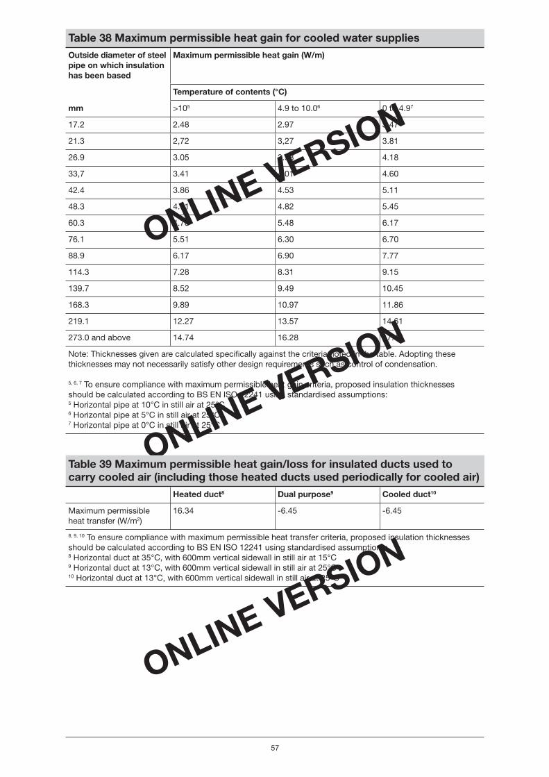
ONLINE VERSION
ONLINE VERSION
ONLINE VERSION
57
Table 38 Maximum permissible heat gain for cooled water supplies Outside diameter of steel pipe on which insulation has been based
Maximum permissible heat gain (W/m)
Temperature of contents (°C)
mm >105 4.9 to 10.06 0 to 4.97
17.2 2.48 2.97 3.47
21.3 2,72 3,27 3.81
26.9 3.05 3.58 4.18
33,7 3.41 4.01 4.60
42.4 3.86 4.53 5.11
48.3 4.11 4.82 5.45
60.3 4.78 5.48 6.17
76.1 5.51 6.30 6.70
88.9 6.17 6.90 7.77
114.3 7.28 8.31 9.15
139.7 8.52 9.49 10.45
168.3 9.89 10.97 11.86
219.1 12.27 13.57 14.61
273.0 and above 14.74 16.28 17.48
Note: Thicknesses given are calculated specifi cally against the criteria noted in the table. Adopting these thicknesses may not necessarily satisfy other design requirements such as control of condensation.
5, 6, 7 To ensure compliance with maximum permissible heat gain criteria, proposed insulation thicknessesshould be calculated according to BS EN ISO 12241 using standardised assumptions: 5 Horizontal pipe at 10°C in still air at 25°C6 Horizontal pipe at 5°C in still air at 25°C 7 Horizontal pipe at 0°C in still air at 25°C
Table 39 Maximum permissible heat gain/loss for insulated ducts used to carry cooled air (including those heated ducts used periodically for cooled air) Heated duct8 Dual purpose9 Cooled duct10
Maximum permissible heat transfer (W/m2)
16.34 -6.45 -6.45
8, 9, 10 To ensure compliance with maximum permissible heat transfer criteria, proposed insulation thicknesses should be calculated according to BS EN ISO 12241 using standardised assumptions: 8 Horizontal duct at 35°C, with 600mm vertical sidewall in still air at 15°C9 Horizontal duct at 13°C, with 600mm vertical sidewall in still air at 25°C 10 Horizontal duct at 13°C, with 600mm vertical sidewall in still air at 25°C
Non_domestic Heating.indd 57Non_domestic Heating.indd 57 17/5/06 16:07:1517/5/06 16:07:15

ONLINE VERSION
ONLINE VERSION
ONLINE VERSION
58
Section 12 Compliance checklist and data input into the National Calculation Methodology tool
The compliance checklist is included in Appendix 2 of this guide. This table lists all the space heating technologies for primary heating, hot water systems, cooling systems and air distribution systems withinthe scope of the Non-domestic Heating, Cooling and Ventilation Compliance Guide and summarises the main compliance requirements. The checklist does not cover the minimum provisions for insulationof pipes and ducts serving heating or cooling systems as given in Section 11 of this guide.
The purpose of the compliance checklist is twofold. The checklist can be used:
• By Building Control Offi cers as a simple means of checking the compliance of a heating, comfort cooling or hot water system;
• By users of the approved building energy performance calculation tools to determine the correctparameters for compliance of heating, comfort cooling or hot water systems to input into the tool. As it is not possible to cover all possible approved calculation tools, this compliancechecklist focuses on the data inputs for the SBEM calculation tool.
Note that other approved calculation tools may be used and the data required are made
transparent in each of the technology-specifi c sections. For example, all of the heating effi ciencycredits are provided for users of other approved calculation tools to incorporate in their models.
The SBEM calculation tool and the accompanying user guide are available from the website (www.ncm.bre.co.uk). Section 6 of the user guide (version 1.0.0) explains how to input data into SBEM relating to Building Services.
How to use the compliance checklist
The compliance checklist is a table summarising the key criteria for compliance with the minimum provisions of the Building Regulations, Part L for heating, hot water, cooling and ventilation systems as detailed in this guide. It is important that building services designers consult individual sections of this guide as using the compliance checklist alone will not enable a full appreciation of the minimum provisions for compliance with Part L.
The checklist is divided into six columns as follows:
Column 1: Technology
This column lists all the space heating systems for primary heating, DHW systems, cooling and air distribution systems covered in the Non-domestic Heating, Cooling and Ventilation Compliance Guide. Column 2: Effi ciency check
This column shows the minimum acceptable effi ciency for each type of heating or cooling system and the maximum permissible specifi c fan power for air distribution systems. These minimum (or,for fans, maximum) acceptable effi ciency values are designated Value A1 to Value A11. The actual design values can be entered in the adjacent sub-column – the design values are designated Value B1 to Value B11. The fi nal sub-column allows a record that the appropriate check has been made.
Column 3: Minimum controls package check
This column displays all the control measures which should be specifi ed as part of the minimum controls package. An entry can be made in the adjacent sub-column to indicate that the check has been made.
Non_domestic Heating.indd 58Non_domestic Heating.indd 58 17/5/06 16:07:1517/5/06 16:07:15

ONLINE VERSION
ONLINE VERSION
ONLINE VERSION
Column 4: Additional controls – heating effi ciency credits check
This column shows all the measures that are additional to the minimum controls package, for which heating effi ciency credits can be gained. The values assigned to each additional measure can be checked and summed to obtain the total Heating Effi ciency Credits. The values for the total heating effi ciency credits are designated value C2 to value C5, and C7 to C8.
Note that heating effi ciency credits are not defi ned for all types of technologies. In some cases it may be acceptable for values C2 or C3, C4, etc. to be zero. This would be the case if the value of the heat generator seasonal effi ciency meets or exceeds the minimum acceptable Effective Heat GeneratingSeasonal Effi ciency as defi ned in each technology-specifi c section of this guide.
Column 5: Summary compliance check
This column describes the key compliance requirements and prompts the user for additional checks where these are not already covered in columns 2, 3 and 4.
Column 6: Data input to NCM tool (SBEM) check
This column indicates the effi ciency value that should be entered in the approved calculation tools.It also indicates the name of the fi eld in SBEM in which the value should be entered, as in some cases the terminology used in SBEM may be different to that used in this guide.
Note that the compliance checklist does not cover data inputs related to building services which may be required by SBEM, other than those which are defi ned in this Non-domestic Heating, Cooling and Ventilation Compliance Guide as a minimum provision for compliance with Part L.
59
Non_domestic Heating.indd 59Non_domestic Heating.indd 59 17/5/06 16:07:1617/5/06 16:07:16

ONLINE VERSION
ONLINE VERSION
ONLINE VERSION
60
Section 13 Glossary
Approved Document L2A ADL2A Approved Document L2A gives guidance on how to satisfy Part L (Conservation of fuel and power in new buildings other than dwellings – 2006 edition) the Building Regulations in common situations. Effective from 6 April 2006.
Approved Document L2B ADL2B Approved Document L2B gives guidance on how to satisfy Part L (Conservation of fuel and power in existing buildings other than dwellings – 2006 edition) of the Building Regulations in common situations for work in non-domestic buildings. Effective from 6 April 2006.
The Building Regulations Statutory Instrument 2000 No. 2531. The Building Regulations ensure the health and safety of people in and around buildings by providing functional requirements for building design and construction.
Offi ce of the Deputy ODPM The government department responsible for producing andPrime Minister revising The Building Regulations. On 5th May 2006 the responsibilities of the ODPM passed to the Department for Communities and Local Government (DCLG).
Non-domestic Heating, This second-tier document in support of ApprovedCooling and Ventilation Documents L2A and L2B setting out the minimum standardsCompliance Guide of provision that meet the requirements of Part L for
conventional space heating, hot water and cooling systems provided in new build other than dwellings and for work in existing buildings other than dwellings.
National Calculation NCM The National Calculation Methodology defi nes the procedureMethodology for demonstrating compliance with the Building Regulations
for buildings other than dwellings. This involves calculating the annual energy use for a proposed building and comparing it with the energy use of a comparable ‘notional’ building. The NCM comprises the underlying method plus the standard data sets. The NCM can be implemented through accredited simulation software or in SBEM.
Simplifi ed Building SBEM A simplifi ed tool underpinned by the National CalculationEnergy Model Methodology and based on a set of CEN standards which
allows the calculation of annual energy use for a proposed building in order to demonstrate compliance with The Building Regulations for buildings other than dwellings.
Accredited NCM tool A tool or model (such as SBEM) which is underpinned bythe National Calculation Methodology which allows the calculation of annual energy use for a proposed buildingin order to demonstrate compliance with The Building Regulations for buildings other than dwellings.
European Committee for CEN CEN produces standards (often at the request of industryStandardization or at the request of the European Commission in order to
implement European legislation). Harmonised CEN standards ensure consistent standards for products which may be manufactured, sold and installed across the EC.
Energy performance rating In this document this refers to the annual energy use predicted for the building using the National Calculation Methodology.
Non_domestic Heating.indd 60Non_domestic Heating.indd 60 17/5/06 16:07:1617/5/06 16:07:16

ONLINE VERSION
ONLINE VERSION
ONLINE VERSION
Appendix 1: Conversion factors
The conversion factors in Table 40 can be used to convert effi ciencies based on calorifi c value from net to gross and gross to net:
• To convert from net effi ciency to gross, multiply by the factor for the appropriate fuel.As an example take a boiler at 80% net effi ciency fi ring LPG. To convert to gross = 80 � 0.921 = 73.68%.
• To convert from gross effi ciency to net, divide by the factor for the appropriate fuel.As an example take a boiler at 73.68% gross effi ciency fi ring LPG. To convert to net = 73.68 � 0.921 = 80.0%.
Table 40 Factors for converting effi ciencies30 Fuel type Conversion factor
Natural gas 0.901
Liquefi ed petroleum gas (LPG) 0.921
Oil 0.937
30 Conversion factors are derived from The Government’s Standard Assessment Procedure for Energy Rating of Dwellings 2005 edition (Table E.3 in Appendix E).
61
Non_domestic Heating.indd 61Non_domestic Heating.indd 61 17/5/06 16:07:1617/5/06 16:07:16

ONLINE VERSION
ONLINE VERSION
ONLINE VERSION
Ap
pen
dix
2: C
om
plia
nce
chec
klis
t
62
Non_domestic Heating.indd 62Non_domestic Heating.indd 62 17/5/06 16:07:1717/5/06 16:07:17
ONLINE VERSION
ONLINE VERSION
ONLINE VERSION

ONLINE VERSION
ONLINE VERSION
ONLINE VERSION
63
Non_domestic Heating.indd 63Non_domestic Heating.indd 63 17/5/06 16:07:1717/5/06 16:07:17
ONLINE VERSION
ONLINE VERSION
ONLINE VERSION
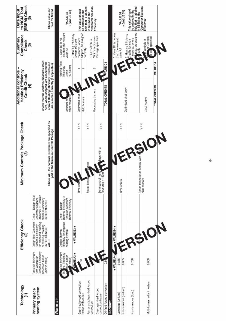
ONLINE VERSION
ONLINE VERSION
ONLINE VERSION
64
Non_domestic Heating.indd 64Non_domestic Heating.indd 64 17/5/06 16:07:1717/5/06 16:07:17
ONLINE VERSION
ONLINE VERSION
ONLINE VERSION

ONLINE VERSION
ONLINE VERSION
ONLINE VERSION
Non_domestic Heating.indd 65Non_domestic Heating.indd 65 17/5/06 16:07:1817/5/06 16:07:18
ONLINE VERSION
ONLINE VERSION
ONLINE VERSION

ONLINE VERSION
ONLINE VERSION
ONLINE VERSION
66
Non_domestic Heating.indd 66Non_domestic Heating.indd 66 17/5/06 16:07:1817/5/06 16:07:18
ONLINE VERSION
ONLINE VERSION
ONLINE VERSION

ONLINE VERSION
ONLINE VERSION
ONLINE VERSION
67
Non_domestic Heating.indd 67Non_domestic Heating.indd 67 17/5/06 16:07:1917/5/06 16:07:19
ONLINE VERSION
ONLINE VERSION
ONLINE VERSION

ONLINE VERSION
ONLINE VERSION
ONLINE VERSION
68
Non_domestic Heating.indd 68Non_domestic Heating.indd 68 17/5/06 16:07:1917/5/06 16:07:19
ONLINE VERSION
ONLINE VERSION
ONLINE VERSION

ONLINE VERSION
ONLINE VERSION
ONLINE VERSION
69
Non_domestic Heating.indd 69Non_domestic Heating.indd 69 17/5/06 16:07:1917/5/06 16:07:19
ONLINE VERSION
ONLINE VERSION
ONLINE VERSION
Published by NBS, part of RIBA Enterprises Ltd, and available from:
RIBA Bookshops Mail Order15 Bonhill StreetLondon EC2P 2EA
Telephone orders/General enquiries: 020 7256 7222Fax orders: 020 7374 2737Email orders: [email protected]
Or order online at:www.thebuildingregs.com
www.thenbs.comwww.thenbs.com
Non-Domestic Heating, Coolingand Ventilation Compliance Guide
May 20061st Edition
© Crown copyright 2006
The Approved Documents are published by NBS for the Department for Communities andLocal Government.
This publication has been approved by Ministers and has official status. Copyright in thecontents, the cover, the design and the typographical arrangement of this publication restswith the Crown unless otherwise stated. The contents of this publication may be reproducedfree of charge in any format or medium for the purposes of private research and studyor for internal circulation within an organisation. This is subject to the contents beingreproduced accurately and not in a way that implies official status. Any publisher wishingto reproduce the content of this publication must not use or replicate the DCLG logoor replicate the official version’s style and appearance, including the cover design, andmust not present their publication as being an official publication as this may confuse thepublic. The reproduced material must be acknowledged as Crown Copyright and the titleof the publication specified. The Office of the Deputy Prime Minister does not accept anyresponsibility for the accuracy and comprehensiveness of any other versions.
Any other use of the contents of this publication would require a copyright licence. Pleaseapply for a licence by writing to the Department for Communities and Local Government,Information Policy Team, St Clements House, 2-16 Colegate, Norwich NR3 1BQ.Fax 01603 723000 or email [email protected] information can be obtained from www.opsi.gov.uk.
ISBN-10 1 85946 226 XISBN-13 978 1 85946 226 3
Stock code 57646
RIBA Bookshops
66 Portland Place, London W1B 1AD. Telephone 020 7256 7222.
113-115 Portland Street, Manchester M1 6DW. Telephone 0161 236 7691.
Birmingham & Midland Institute, Margaret Street, Birmingham B3 3SP. Telephone 0121 233 2321.
RSUA, 2 Mount Charles, Belfast BT7 1NZ. Telephone 028 9032 3760.
Renew Rooms, 82 Wood Street, Liverpool L1 4DQ. Telephone 0151 707 4380.


