Ariel Etinger, Nezah Balal, Boris Litvak, Moshe Einat, Boris Kapilevich, Senior Member, IEEE,and Yosef Pinhasi
Abstract— This paper describes a millimeter-wave sensor thatis able to detect pedestrians, thereby reducing the likelihoodof human road injuries or fatalities. The sensor consists of atransmit/receive channel module, operating in the millimeter-wave range (W-band) using frequency-modulated-continuous-wave mode. The laboratory prototypes of the sensor have beendesigned and tested in real-life environment. An analysis ofsystem performance and experiments conducted has indicateda high-resolution, detection ability of both adults and childrenat a distance of up to 100–150 m.
Index Terms— Road safety, radar detection, millimeter wavesensor, FMCW systems.
I. INTRODUCTION
PEDESTRIAN safety is a major modern-day concern.According to the ‘Global Road Safety Partnership’ site,
“Every day, more than 3,000 people around the world losetheir lives due to road crashes. Half of these deaths are vul-nerable road users such as pedestrians [1]”. Many accidents arethe result of driver inattention or difficult weather conditionscausing poor visibility, as well as pedestrian inattentivenessto their surroundings [2]. Some advanced systems, typicallyoptical or IR, designed for optimal performance in goodvisibility conditions, include warning sensors to alert drivers orif necessary, control the vehicle in an emergency situation [3].
A system based on optical or IR cameras has been deployedfor the purpose of identifying nearby objects, that would eitherwarn the driver or stop the vehicle altogether when an accidentis imminent [4]. An important parameter of these systems isthe detection range; if this parameter is increased, then thedriver would be given considerably more time to respond.It has been demonstrated that with a 24GHz radar, a pedestriancan be detected at a distance of up to 30m [5], and that dataprocessing can be used to identify the pedestrian’s azimuthallocation at a ∼7m distance [6]. Various means are beingexplored so as to extend this range, including integration withan IR system [7], integration with an optical camera extendingdetection range to 50m [8], and thermal imaging [9].
Manuscript received September 25, 2013; revised October 31, 2013;accepted November 25, 2013. Date of publication December 3, 2013; dateof current version February 21, 2014. The associate editor coordinating thereview of this paper and approving it for publication was Dr. David Hecht.
Color versions of one or more of the figures in this paper are availableonline at http://ieeexplore.ieee.org.
Digital Object Identifier 10.1109/JSEN.2013.2293534
The primary issue with optical systems is the fact that theycannot operate at night, and also suffer from significant atten-uation in extreme weather conditions (up to 100 dB/km). Thatsaid, it has been shown that extreme weather does increasethe frequency of road accidents [10]. One possible solutionwould be to use systems operating in the 77–95 GHz wherethe attenuation is 1–3 dB/km in extreme weather conditions,e.g. 100 percent humidity or heavy fog [11].
Another alternative approach involves the development ofmm-wave imaging systems. In the course of the past twodecades, there have been various attempts, both active andpassive, at realising such systems [12]–[15] however, theircomplexity and short-range operation pose considerable lim-itations in the application of such systems for pedestriandetection at a range of ∼100m.
In this article, we aim to examine the ability of the FMCWsensor, operating in W-band, (75–110 GHz) to help preventingvehicular accidents involving pedestrians. Assessing the sen-sor’s potential is done by factoring in expected system perfor-mance, and also via experimental verification. The basic RadioFrequency (RF) components of the laboratory prototype areavailable off-the-shelf; however, some of them were designedand assembled in Ariel University’s RF-Microwave-MM wavelab, e.g. the voltage-controlled Oscillator (VCO) with atriangle-shaped modulator; a Lab-View interface matched withData Acquisition (DAQ), and a programmable positioner usedin experiments. Preliminary experiments [16] have proven thatsuch sensors do in fact possess the ability to detect targets,characterized by a small Radar Cross-Section (RCS) that istypical to pedestrians.
II. HARDWARE CONFIGURATION
The block diagram of the sensor discussed below is shownin Fig. 1. The key element of the sensor is a Voltage-Controlled Oscillator (VCO) modulated by a triangular wavesignal. It was built using Hititte VCO module HMC632 [17]operating in the f = 14.25−15.65 GHz frequency range witha 9 dBm output power. We have actually used a slightlyhigher frequency range than indicated on the data sheet inorder to generate a chirp at a frequency of 15.6–15.8 GHz.However, experiments have shown that the component has infact remained linear in the workspace.
In order to create the chirp signal, we used the ana-logue output from the National Instruments’ data acquisitioncard (DAQ), model NI USB 6251, controlled by a com-puter which forms a 33 Hz triangular wave with a voltage
ETINGER et al.: NON-IMAGING MM-WAVE FMCW SENSOR FOR PEDESTRIAN DETECTION 1233
Fig. 1. Block diagram of the FMCW sensor.
range of 8.2–9.2 V. This wave controls the VCO whichproduces a proper FMCW signal. An x6 frequency multiplier(Millitech AMC-10-RFHOO) was used to obtain the chirp inthe 93.6–94.8 GHz range.
The Tx channel consists of a Gaussian-beam antennathat is 7cm in diameter with a 35dBi gain and a 3-degreebeamwidth (QuinStar QLA-WOOYO3C). The power transmit-ted is 10mW. The back-scattered echoes from the target werereceived using the identical antenna in the Rx channel, ampli-fied by a Low-Noise Amplifier (LNA) (QuinStar MN-QLN-94046028-12), and then mixed with the transmitted signal,using a Mixer (ELVA-1-BM-10-F). A Low Pass Filter (LPF)with a 30kHz cutoff was added to suppress the out-band noise.
The intermediate frequency (IF) signal was sampled usingthe same DAQ. The signal processing is flexible and differentthreshold-detection-level settings can be pre-installed for thepurposes of adapting to a real-life environment. The resultsobtained from the system are sampled every 1/10 of a second.The information is processed by Lab-View software. Process-ing takes a number of milliseconds, after which the receivedenvelope is displayed on the laptop screen. The measurementresults are displayed in real-time. A general view of sensor isshown in Fig. 2.
III. SYSTEM PERFORMANCE CONSIDERATIONS
A. Noise Performance and Minimum Detectable Signal (MDS)
The received power can be estimated using the radar equa-tion. Assuming the RCS of a human body σ is about 1 m2
[15] and the transmission power Pt = 10 mW, the amount ofreceived power Pr,min at a maximum distance dmax of 60mcan be calculated using the radar range equation, given by
Pr,min = Pt · Gr · Gt · λ2 · σ(4π)3 · d4
max(1)
For transmitting and receiving antenna gains Gt = Gr =35 dB, we compute Pr,min = −74 dBm.
The noise figure calculations are based on the components’datasheet: The noise figure of LNA is Famp max = 6dB,the LNA minimum Gain is 28 dB, the conversion loss of amixer is CLmix = 7.8dB and the insertion loss of LPF is
Fig. 2. Photograph of the FMCW sensor.
FL P F = 0.5dB.
FT OT ,Max = Famp,Max + (C L Mix − 1)
Gamp,min
+ (FL P F,Max − 1)C L Mix
Gamp,min(2)
The total system noise figure was calculated according toEq. (2) and was found to be ∼6 dB, approximately same asthat of the low noise amplifier on account of its high gain. Thenoise floor, PNF, given by kB · T · B · FT OT ,max, where kB isthe Boltzmann constant (1.38 × 10⁻²³ J/K), T , the ambi-ent temperature (290 K), B , the bandwidth (30 kHz), andFT OT ,max, the front-end noise figure (6 dB) is computedas −123.17 dBm.
Using the values for the minimum received power andthe noise floor, the signal-to-noise ratio (SNR) at 60m isobtained as 49.17 dB. The distance of 60m was selected as thisdetection distance allows not only for a warning but also foran automatic slowing down, and even for a complete haltingof the vehicle. From this calculation it emerges that detectionat even larger distances is feasible under these terms.
The minimum detectable signal, assuming a SNRout,min of12 dB is then computed as −111.17 dBm.
Actual contributions of different RF components to theoverall system noise-performance also depend on a specifichardware structure and may vary across a wide range. How-ever, the above-estimated performance can be realized usingcommercially-available components. In this configuration, thenoise is more dominant than the minimum detectable signal.
B. Antenna Mutual Coupling
Mutual coupling between antennas can be a source of theparasitic leakage that leads to degrading overall system noiseperformance, and to saturating front-end LNA. The couplingeffect depends on both the polarization and distance betweenantennas. As an illustrating example, the transmittance mag-nitude S21 between the two ports of identical horn-antennaswith radiating apertures 18 × 25mm2 and zero spacing wasestimated in the 90–100GHz range. The antennas’ two ori-entations were simulated using a 3D EM solver (CST-12):side-by-side (H-plane) and collinear (E-plane). Fig. 3 showsthe role of polarization in the mutual coupling of the two horn
1234 IEEE SENSORS JOURNAL, VOL. 14, NO. 4, APRIL 2014
Fig. 3. The mutual coupling effect between two horn antennas, for H and Eplanes.
antennas. The comparison of both cases clearly demonstratesthat the H-plane structure allows for the reducing of thecoupling to about 80dB, due to minimal electric field presenceon the metal walls. On the other hand, the E-plane structuresuffers from edge diffraction leading to an increase in mutualcoupling. Therefore H-plane configuration was employed inthe experiments described below.
From the system’s point-of-view, the sensor with theseparated antennas is simpler in comparison with its singleantenna counterpart, seeing as there is no need for a cir-culator, a PIN switch, and additional couplers for leakagecancelling [19]. However, the overall dimensions of sensorwith the separated antennas are larger as the antennas areultimately in charge of this parameter.
IV. LAB-VIEW INTERFACE AND PROCESSING ALGORITHM
The IF signal in crude form, comes out of the mixer outputand needs the initial processing. The first step is to apply theFFT (Fast Fourier Transform) to the signal in order to analyzethe components of the received signal frequencies.
FFT processing is a complete, structured program (feature)in Lab-View. This program can set a number of processingelements, e.g. averaging or window filtering, etc. The timeduration used for FFT processing is defined by the samplingrate and number of samples taken at a certain, given time.A timeframe of 0.1 s was used. The signal obtained aftertransformation corresponds with various frequencies, depend-ing on the distance to targets. In order to view the resultsin convenient form, proper normalization to the distance wasadded prior to their displaying on the X-axis. This processingwas done in the Lab-View interface which also features a graphshowing the distance to a target, after applying the following
formula [15, p. 87]:Ddistance = c · �t
2 · � f· f (3)
Where:Ddistance-distance between the sensor and target,f – frequency obtained after FFT, c – speed of light invacuum, �t – period of the modulation signal, � f -frequency band of modulation signal. Factor 2 is needed toaccount for the signal’s completion of a “roundtrip”. Theparameters of the transmitted signal were:
�t = 0.03s
� f = 1.2G H z
Therefore, the conversion coefficient is:
Ddistance = 0.625 · 10−3 · f (4)
The minimum detectable distance is less than 1m while therange resolution is
�d = c
2 · � f∼= 12.5cm (5)
V. EXPERIMENTS
Experiments were conducted with the aforementioned radarin various environments and targets. Firstly, range calibrationmeasurements were taken with a corner reflector to verifythe radar’s range readings. Then, both adult and child mea-surements were taken in a ‘road-like’ environment, and ina grassy soccer field. Measurements were taken in real timeusing the LabView, and also, post processing was done usingMatlab. Several rounds of experiments were conducted and theconclusions from the MATALAB analysis were implementedinto the LabView code to enhance the real time algorithm. Theexperimental results were as follows.
The threshold level varied while integration over variousnumbers of transmitted cycles was checked experimentally, inorder to determine the best setting for a given environment.The experiment was conducted in a parking area. That par-ticular setting was chosen as it provides an environment withrather similar conditions to what one might expect to encounteron the road. The sensor output was processed by the LabView code while the results appeared on a laptop screen inreal time. Additionally, the raw detection results were savedfor the purpose of being used in post processing if necessary.An example of such reading is shown in Fig. 5 where thetarget is an eight-year-old child at 60m as seen in Fig. 4.
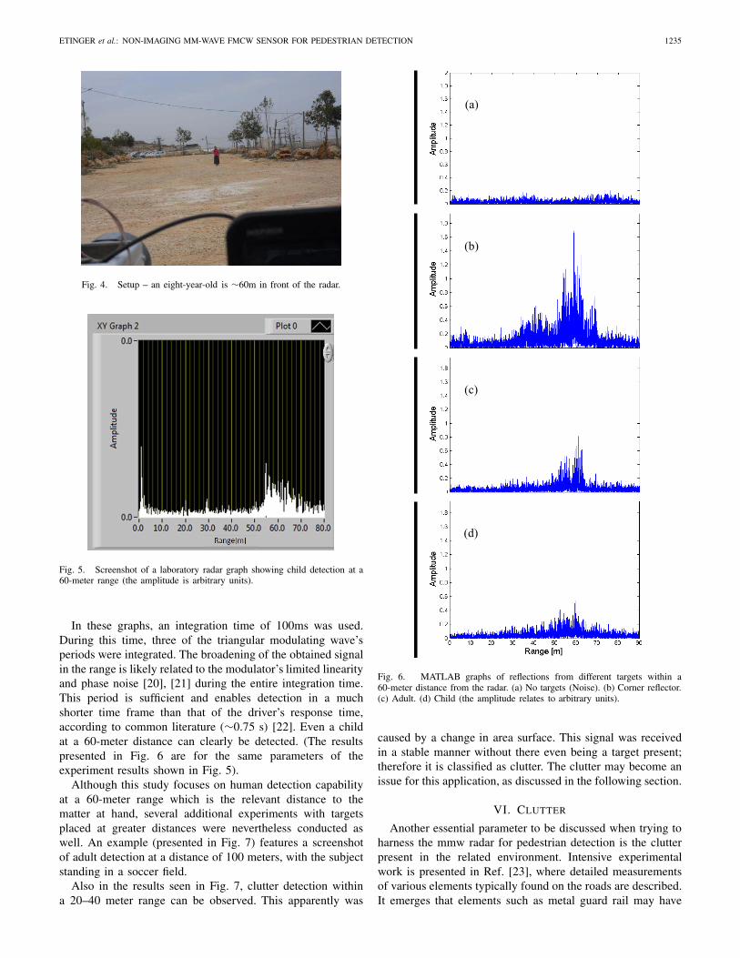
Here, one might see that a signal was recorded well abovethe noise level, thus enabling the detection of this target.The results were then transferred to MATLAB for furtherprocessing and convenient presentation. Different types ofintegration methods were used and compared. The methodwhich gave the best result was implemented in the Lab-Viewreal time code. Several of the post-processing graphs are asfollows:
• Empty field reflections – noise only [Fig. 6(a)].• Corner reflector at 60 m [Fig. 6(b)]• An adult at 60 m [Fig. 6(c)]• A child at 60 m [Fig. 6(d)]
ETINGER et al.: NON-IMAGING MM-WAVE FMCW SENSOR FOR PEDESTRIAN DETECTION 1235
Fig. 4. Setup – an eight-year-old is ∼60m in front of the radar.
Fig. 5. Screenshot of a laboratory radar graph showing child detection at a60-meter range (the amplitude is arbitrary units).
In these graphs, an integration time of 100ms was used.During this time, three of the triangular modulating wave’speriods were integrated. The broadening of the obtained signalin the range is likely related to the modulator’s limited linearityand phase noise [20], [21] during the entire integration time.This period is sufficient and enables detection in a muchshorter time frame than that of the driver’s response time,according to common literature (∼0.75 s) [22]. Even a childat a 60-meter distance can clearly be detected. (The resultspresented in Fig. 6 are for the same parameters of theexperiment results shown in Fig. 5).
Although this study focuses on human detection capabilityat a 60-meter range which is the relevant distance to thematter at hand, several additional experiments with targetsplaced at greater distances were nevertheless conducted aswell. An example (presented in Fig. 7) features a screenshotof adult detection at a distance of 100 meters, with the subjectstanding in a soccer field.
Also in the results seen in Fig. 7, clutter detection withina 20–40 meter range can be observed. This apparently was
Fig. 6. MATLAB graphs of reflections from different targets within a60-meter distance from the radar. (a) No targets (Noise). (b) Corner reflector.(c) Adult. (d) Child (the amplitude relates to arbitrary units).
caused by a change in area surface. This signal was receivedin a stable manner without there even being a target present;therefore it is classified as clutter. The clutter may become anissue for this application, as discussed in the following section.
VI. CLUTTER
Another essential parameter to be discussed when trying toharness the mmw radar for pedestrian detection is the clutterpresent in the related environment. Intensive experimentalwork is presented in Ref. [23], where detailed measurementsof various elements typically found on the roads are described.It emerges that elements such as metal guard rail may have
1236 IEEE SENSORS JOURNAL, VOL. 14, NO. 4, APRIL 2014
Fig. 7. Screenshot of human detection distance of 100 meters with the sensor(The amplitude is in arbitrary units).
a much higher RCS than the human target. Clearly a practicalsolution will have to include methods of removing the clutter.One parameter which distinguishes a human target from clutteris the fact that the latter is almost entirely static, whereas theformer is moving. Therefore, Moving Target Indicator (MTI)and Doppler analysis may have to be used in order to eliminatethe clutter. Another parameter that can be used for the elimi-nation of clutter is the location of clutter targets. If a locationcoming from a GPS system and road maps supplies data to thesystem, then the radar can classify targets that are not on theroad as clutter and subsequently exclude them. Furthermore,accumulated data on the road can predict the constant expectedclutter and help the radar exclude clutter targets.
VII. CONCLUSION
The mm-wave sensor, geared towards real-time pedestrian-detection has been presented. The architecture of the sensorwas based on the FMCW Rx-Tx module using the two inde-pendent Gaussian-beam antennas. The preliminary analysis ofthe link budget proves an ability to assemble the prototypingradar system from already market-available components. TheLab-View interface was designed and employed for processingand evaluating distance to detected targets. The sensor isindeed capable of detecting adults and children at a distanceof up to 100m.
ACKNOWLEDGMENT
The authors would like to thank A. Schulzinger for thedesign of electronics options, S. Neporent for assisting inmechanical works and D. Hardon for coordinating this work.
REFERENCES
[1] GRSP, Savannah, GA, USA. (2011). Working Together for a Decadeof Action on Road Safety (2011–2020) http://www.grsproadsafety.org/sites/grsp.drupalgardens.com/files/GRSP_brochure.pdf
[2] T. Gandhi and M. M. Trivedi, “Pedestrian protection systems: Issues,survey, and challenges,” IEEE Trans. Intell. Transp. Syst., vol. 8, no. 3,pp. 413–430, Sep. 2007.
[3] S. N. Lu, H. W. Tseng, Y. H. Lee, Y. G. Jan, and W. C. Lee, “Intelligentsafety warning and alert system for car driving,” Tamkang J. Sci. Eng.,vol. 13, no. 4, pp. 395–404, 2010.
[4] T.-H. Chang, C.-S. Hsu, C. Wang, and L.-K. Yang, “Onboard measure-ment and warning module for irregular vehicle behavior,” IEEE Trans.Intell. Transp. Syst., vol. 9, no. 3, pp. 501–513, Sep. 2008.
[5] T. Matthias, D. Reiner, M. Marc-Michael, and O. Marian Andrzej,“Radar sensors and sensor platform used for pedestrian protection in theEC-funded project SAVE-U,” in Proc. IEEE Intell. Veh. Symp., Parma,Italy, Jun. 2004, pp. 813–818.
[6] F. Fölster and H. Rohling, “Data association and tracking for automo-tive radar networks,” IEEE Trans. Intell. Transp. Syst., vol. 6, no. 4,pp. 370–377, Dec. 2005.
[7] In the Matter of Allocations and Service Rules for the 71–76 GHz,81–86 GHz, and 92–95 GHz Bands, Federal Commun. Commission,Washington, DC, USA, Nov. 2003.
[8] T. Kato, Y. Ninomiya, and I. Masaki, “An obstacle detection method byfusion of radar and motion stereo,” IEEE Trans. Intell. Transp. Syst.,vol. 3, no. 3, pp. 182–188, Sep. 2002.
[9] D. T. Linzmeier , M. Skutek, M. Mekhaiel, and K. C. J. Dietmayer,“A pedestrian detection system based on thermopile and radar sensordata fusion,” in Proc. IEEE 8th Int. Conf. Inf. Fusion, vol. 2. Jul. 2005,pp. 1–8.
[10] H. Wu and S. Malipeddi, “Influential factors for severe traffic crashes,”in Proc. IEEE ICVES, Jul. 2011, pp. 71–75.
[11] Y. Pinhasi, A. Yahalom, O. Harpaz, and G. Vilner, “Study of ultrawide-band transmission in the extremely high frequency (EHF) band,” IEEETrans. Antennas Propag., vol. 52, no. 11, pp. 2833–2842, Nov. 2004.
[12] L. Yujiri, M. Shoucri, and P. Moffa, “Passive millimeter wave imaging,”IEEE Microw. Mag., vol. 4, no. 3, pp. 39–50, Sep. 2003.
[13] R. Appleby, “Passive millimeter–wave imaging and how it differs fromterahertz imaging,” Phil. Trans. R. Soc., London Ser. A, Math., Phys.Eng. Sci., vol. 362, no. 1815, pp. 379–393, Feb. 2004.
[14] D. M. Sheen, D. L. McMakin, W. M. Lechelt, and J. W. Griffin,“Circularly polarized millimeter–wave imaging for personnel screening,”Proc. SPIE, vol. 5789, pp. 117–126, Apr. 2005.
[15] M. I. Skolnik, Introduction to Radar Systems. New York, NY, USA:McGraw-Hill, 1962.
[16] B. Kapilevich and M. Einat, “Detecting hidden objects on human bodyusing active millimeter wave sensor,” IEEE Sensors J., vol. 10, no. 11,pp. 1746–1752, Nov. 2010.
[17] Hittite Microwave Corporation Company Web, Chelmsford, MA, USA.(2013). Data-Sheet of VCO HMC632 Component [Online]. Available:http://www.hittite.com/content/documents/data_sheet/hmc632lp5.pdf
[18] B. Kapilevich, Y. Pinhasi, M. Anisimov, B. Litvak, and D. Hardon,“FMCW MM-wave non-imaging sensor for detecting hidden objects,”in Proc. IEEE MTT-S IMWS, Sitges, Spain, Sep. 2011, pp. 664–667.
[19] P. D. L. Beaslev and A. G. Stove, “PILOT—An example of advancedFMCW techniques,” in Proc. IEE Colloq. High Time-Bandwidth ProductWaveforms Radar Sonar, May 1991, pp. 101–105.
[20] M. Vossiek, P. Heide, M. Nalezinski, and V. Magori, “Novel FMCWradar system concept with adaptive compensation of phase errors,” inProc. 26th Eur. Microw. Conf., Sep. 1996, pp. 135–139.
[21] H. D. Griffiths, “The effect of phase and amplitude errors in FM radar,”in Proc. IEE Colloq. High Time-Bandwidth Product Waveforms RadarSonar, London, U.K., May 1991, pp. 91–95.
[22] Y. Wu, H. Yuan, H. Chen, and J. Li, “A study on reaction timedistribution of group drivers at car-following,” in Proc. 2nd ICICTA,vol. 3. Changsha, China, Oct. 2009, pp. 452–455.
[23] R. M. Narayanan and B. R. J. Snuttjer, “Millimeter-wave backscattermeasurements in support of surface navigation applications,” Int. J. Infr.Millim. Waves, vol. 18, no. 11, pp. 2077–2109, Nov. 1997.
Ariel Etinger received the B.Sc. degree in electronicengineering and the B.A. degree in applied physicsfrom Israel’s Ariel University in 2009, where heis currently pursuing the M.A. degree in electricalengineering. His research interests include radarsystems, image processing, intelligent transportationsystems, and signal processing.
He has been involved with research and develop-ment with the mm Wave Laboratory, Ariel Univer-sity, since 2012.
ETINGER et al.: NON-IMAGING MM-WAVE FMCW SENSOR FOR PEDESTRIAN DETECTION 1237
Nezah Balal is currently pursuing the Graduatedegree with the Department of Electrical and Elec-tronic Engineering, Faculty of Engineering, ArielUniversity. He was born in Israel, in 1982. Hereceived the B.Sc. degree in physics in 2010 andin electrical engineering in 2011 from the ArielUniversity of Samaria.
He has been with the Electromagnetic ResearchLaboratory, since 2011, involved in remote sensingradars, operating in the millimeter, and terahertzregimes.
Boris Litvak is an Engineer of the Microwave andMM-Wave Group, Center for Radiation Sources andApplications, Ariel University, Israel. He has pub-lished over 20 papers and articles on RF-microwave-mm wave-engineering and microwave materialcharacterization.
Moshe Einat received the B.Sc., M.Sc., and Ph.D.degrees from Tel-Aviv University. He is a SeniorLecturer with the Engineering Faculty, Ariel Uni-versity, Israel. He has specialized in high-powermicrowave electron tubes, integrated to a ferro-electric cold electron gun. He conducts experimen-tal research on various projects in the field ofmicrowave, millimeter, and THz waves, both fromgeneration and application points of view.
Boris Kapilevich (M’94–SM’97) is a Full Professorof microwave engineering with the Ariel University,Israel. He has authored or co-authored four books,holds 15 patents, and has published over 150 papersdedicated to both active and passive microwavedevices, the theory of guided waves, electromagnet-ics, measurements and material characterization, andmm-wave imaging.
Yosef Pinhasi is the Dean with the Faculty ofEngineering, Ariel University. He was born in Israel,in 1961. He received the B.Sc., M.Sc., and Ph.D.degrees in electrical engineering from Tel-Aviv Uni-versity, Israel, in 1983, 1989, and 1995, respectively.He was the Head of the Department of Electrical andElectronic Engineering from 2004 to 2007.
He has been working in the field of electro-magnetic radiation, investigating mechanisms of itsexcitation and generation in high-power radiationsources like microwave and millimeter wave electron
devices, free-electron lasers and masers since 1990. He has developed aunified, coupled-mode theory of electromagnetic field excitation and prop-agation in the frequency domain, enabling the study of wideband interactionsof electromagnetic waves in media, in both linear and nonlinear (saturation)operation regimes.
Prof. Pinhasi researches the utilization of electromagnetic waves in a widerange of frequencies for various applications such as communications, remotesensing, and imaging. The space-frequency approach, developed by him, isemployed for the purposes of studying the propagation of wide-band signalsin absorptive and dispersive media in broadband communication links, inwireless, indoor and outdoor networks, and in remote sensing radars operatingin the millimeter and terahertz regimes.