Tenth U.S. National Conference on Earthquake Engineering Frontiers of Earthquake Engineering July 21-25, 2014 Anchorage, Alaska 10NCEE NON-LINEAR DYNAMIC AND STATIC ANALYSIS OF SIX SPAN RC BOX GIRDER BRIDGE WITH HIGH HOLLOW PIERS: DISCUSSION AND COMPARISON N. Serdar 1 , J. Pejovic 2 , R. Pejovic 3 ABSTRACT This paper will present comparison of results obtained from non-linear dynamic analysis and static push-over analysis applied on box girder bridge with very high RC hollow rectangular piers. Analysis was conducted on already designed bridge that is going to be built on highway of Montenegro. Continuous box girder bridge, with total length of 960 meters has six spans length of 130-4x175-130 meters and columns whose heights varies from 80 meters (first and last pier) to 165 meters for each of three central columns. Bridge was designed for seismic earthquake resistance according European code EC 8-2. Also NDA and push-over analysis were conducted according to European standards and recommendation. Nonlinear model was built in software perform3D, using concentrated plasticity model approach. Engineering demand parameters were chosen to represent structural performance, and they were checked and monitored during loading. Results from two analyses were compared, and it was concluded that globally structure had same response under applied seismic input, but expectably push-over analysis under estimated some structural behaviors like column sheer demand/capacity factor. Conclusions about improving bridge design were made, and some deficits in applied regulation were noticed. 1 Phd Student Researcher, Dept. of Civil Engineering, University of Montenegro 2 Phd Student Researcher, Dept. of Civil Engineering, University of Montenegro 3 Professor, Dept. of Civil Engineering, University of Montenegro Serdar N, Pejovic J, Pejovic R. Non-linear dynamic and static analysis of six span RC box girder bridge with hollow piers: Discussion and comparison. Proceedings of the 10 th National Conference in Earthquake Engineering, Earthquake Engineering Research Institute, Anchorage, AK, 2014.
Transcript
Tenth U.S. National Conference on Earthquake EngineeringFrontiers of Earthquake Engineering July 21-25, 2014 Anchorage, Alaska 10NCEE
NON-LINEAR DYNAMIC AND STATIC ANALYSIS OF SIX SPAN RC BOX GIRDER
BRIDGE WITH HIGH HOLLOW PIERS: DISCUSSION AND COMPARISON
N. Serdar1, J. Pejovic2, R. Pejovic3
ABSTRACT This paper will present comparison of results obtained from non-linear dynamic analysis and static push-over analysis applied on box girder bridge with very high RC hollow rectangular piers. Analysis was conducted on already designed bridge that is going to be built on highway of Montenegro. Continuous box girder bridge, with total length of 960 meters has six spans length of 130-4x175-130 meters and columns whose heights varies from 80 meters (first and last pier) to 165 meters for each of three central columns. Bridge was designed for seismic earthquake resistance according European code EC 8-2. Also NDA and push-over analysis were conducted according to European standards and recommendation. Nonlinear model was built in software perform3D, using concentrated plasticity model approach. Engineering demand parameters were chosen to represent structural performance, and they were checked and monitored during loading. Results from two analyses were compared, and it was concluded that globally structure had same response under applied seismic input, but expectably push-over analysis under estimated some structural behaviors like column sheer demand/capacity factor. Conclusions about improving bridge design were made, and some deficits in applied regulation were noticed.
1 Phd Student Researcher, Dept. of Civil Engineering, University of Montenegro 2 Phd Student Researcher, Dept. of Civil Engineering, University of Montenegro 3 Professor, Dept. of Civil Engineering, University of Montenegro Serdar N, Pejovic J, Pejovic R. Non-linear dynamic and static analysis of six span RC box girder bridge with hollow piers: Discussion and comparison. Proceedings of the 10th National Conference in Earthquake Engineering, Earthquake Engineering Research Institute, Anchorage, AK, 2014.
Tenth U.S. National Conference on Earthquake EngineeringFrontiers of Earthquake Engineering July 21-25, 2014 Anchorage, Alaska 10NCEE
Non-linear dynamic and static analysis of six span RC box girder bridge
with hollow piers: Discussion and comparison
N. Serdar1, J.Pejovic2, R.Pejovic3
ABSTRACT This paper will present comparison of results obtained from non-linear dynamic analysis and static
push-over analysis applied on box girder bridge with very high RC hollow rectangular piers. Analysis was conducted on already designed bridge that is going to be built on highway of Montenegro. Continuous box girder bridge, with total length of 960 meters has six spans length of 130-4x175-130 meters and columns whose heights varies from 80 meters (first and last pier) to 165 meters for each of three central columns. Bridge was designed for seismic earthquake resistance according European code EC 8-2. Also NDA and push-over analysis were conducted according to European standards and recommendation. Nonlinear model was built in software perform3D, using concentrated plasticity model approach. Engineering demand parameters were chosen to represent structural performance, and they were checked and monitored during loading. Results from two analyses were compared, and it was concluded that globally structure had same response under applied seismic input, but expectably push-over analysis under estimated some structural behaviors like column sheer demand/capacity factor. Conclusions about improving bridge design were made, and some deficits in applied regulation were noticed.
Introduction Non-linear analyses are often necessary in engineering practice for evaluating behaviour of existing and new constructions under seismic loads. Often results obtained from linear analyses do not provide information about real response of the construction during earthquake, and many uncertainties may stay even after applying regulation in designing and detailing of the construction. Value of the investment, demanded post-earthquake functionality of bridge, reducing damage to acceptable level are motives for evaluating preliminary design of bridge construction and bringing construction in desirable behaviour. Non-linear dynamic time history (NDA) and static push-over analysis (NSA), are often used to obtained bridge response. Push-over analysis has many disadvantages in comparison to NDA especially when the system cannot be approximated by generalized single-degree-of freedom system. Still when all of conditions are met that construction can be approximated with one degree of freedom (straight bridges, column’s height decrease towards the abutments etc.) results of push-over analysis can be discussed and compared with NDA results with goal to evaluate suitability of push-over analysis
1 Phd Student Researcher, Dept. of Civil Engineering, University of Montenegro 2 Phd Student Researcher, Dept. of Civil Engineering, University of Montenegro 3 Professor, Dept. of Civil Engineering, University of Montenegro Serdar N, Pejovic J, Pejovic R. Non-linear dynamic and static analysis of six span RC box girder bridge with hollow piers: Discussion and comparison. Proceedings of the 10th National Conference in Earthquake Engineering, Earthquake Engineering Research Institute, Anchorage, AK, 2014.
in bridges. Next step after structural analysis is relating structural response with earthquake intensity, which can be useful for predicting bridge behaviour for different intensity level. Furthermore, analyses can lead to damage estimation and loss estimation what is not subject of this paper.
Description of the bridge construction Bridge is located on future highway that is going to be built in Montenegro. Bridge was already designed by the team of engineers according to national rule book of specifications for designing bridges and for seismic design European standard EN 1998-2 was used [1]. At this level slightly more that preliminary design exists for this construction, further analysis needs to be done to be considered that a main project is completed. This paper presents part of additional analysis. Due to specific features of the valley that this bridge is crossing and due to the value of whole investment, several bridges were designed, but in this paper only one of the solutions is going to be evaluated for its seismic behaviour. This bridge is a continuous six span concrete bridge with cast-in place post-tensioned box girder deck. The inner four spans are 175m (572ft) and the outer two are 130m (425ft). Width of the deck is 22.7m (74ft) and it was designed to carry 4 lines of traffic. Height of the superstructure varies from 3.5m (11ft) in the middle of the spans and over the abutments to 10m (33ft) over the middle columns, see Fig. 1. Height of the columns decreases towards to abutments, and the their cross section over the height also varies, see Fig. 2. Height of the columns from first (S1) to last (S5) are 75.2m (246ft), 167.2m (547ft), 165m (540ft), 152.4m (498ft) and 85.7m (280ft). The deck is supported over the abutments on expansion bearings and it is fixed over the columns. Bridge deck concrete and column concrete were assumed to have unconfined compressive strength of 35MPa and 30MPa respectively. Confined concrete compressive strength were calculated according to literature [2]. According to geotechnical research bridge is founded on very stiff rock with capacity of carrying of 1000kN/m2.
2 % 2 %i % i %
Figure 1. Deck cross section over columns and in the middle of the span Bridge was assumed to be in 3rd class of importance (according to EN 1998-2 this assumption increase seismic forces by 30%) so corresponding PGA for the location is 0.273g with return period of 475 years. Longitudinal reinforcement in one direction is 2x110#25 and in another 2x352#25 which corresponds to reinforcement ratio of 1%. The transverse reinforcement is #12 with longitudinal spacing sL=12.5cm and transverse spacing sT=20cm which corresponds to approximately 0.2% reinforcement ratio in both orthogonal directions. Longitudinal and transverse reinforcement is obtained from minimum amount of reinforcement according to EN 1998-2. Here to say, dimensions of piers were conditioned by bridge’s cantilever type of construction. This type of construction was a logical choice by economic parameters considering configuration of valley and existing road infrastructure.
4-4 5-5 7-76-6
1 0 %
+165.11
+275.16
01
S1
S2 S3
S4 S5 02
+80.08
44
55
66
77
Figure 2. Bridge configuration and column cross section
Seismic input
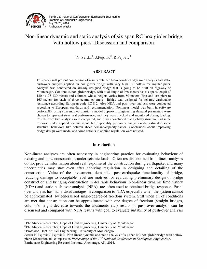
For the purpose of this study two analyses were conducted: nonlinear dynamic time-history analysis and static push-over analysis. Response of the structure obtained from these two analyses will be later compared and commented. In time-history analysis seven pairs of horizontal ground motion were selected according to EN 1998-2 from the European strong-motion database [3]. For each of these seven pairs SRSS spectrum was constructed and their average SRSS spectrum is multiplied so that is not lower than 1.3 times the 5% damped elastic response spectrum of the designed seismic action, in the period range between 0.2T and 1.5T (T is natural period of fundamental mode). In such way derived scaling factor was used for multiplying all individual seismic motion components. Two horizontal ground motion components of the same earthquake act simultaneously. Vertical ground motion component is not considered. Magnitudes of the selected earthquake are between 6 and 7 with distance from the fault between 10 and 35 km. Selected earthquakes are listed in Table 1. SRSS spectrum for each event and their average are shown in Fig.3. Table 1. Ground motion set used in NDA
N Wave ID
Earthquake ID
Station ID
Earthquake name
Date M Fault dist.
PGA_x PGA_y
1 198 93 ST64 Montenegro 4/15/1979 6.9 21 1.7743 2.1985
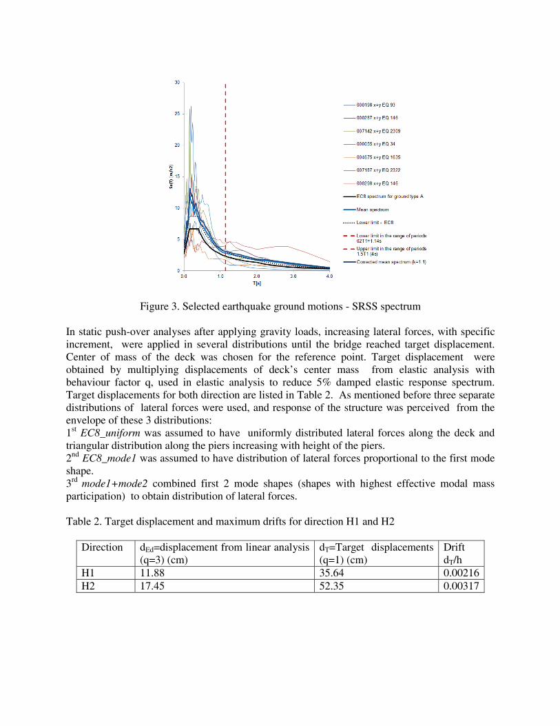
In static push-over analyses after applying gravity loads, increasing lateral forces, with specific increment, were applied in several distributions until the bridge reached target displacement. Center of mass of the deck was chosen for the reference point. Target displacement were obtained by multiplying displacements of deck’s center mass from elastic analysis with behaviour factor q, used in elastic analysis to reduce 5% damped elastic response spectrum. Target displacements for both direction are listed in Table 2. As mentioned before three separate distributions of lateral forces were used, and response of the structure was perceived from the envelope of these 3 distributions: 1st EC8_uniform was assumed to have uniformly distributed lateral forces along the deck and triangular distribution along the piers increasing with height of the piers. 2nd EC8_mode1 was assumed to have distribution of lateral forces proportional to the first mode shape. 3rd mode1+mode2 combined first 2 mode shapes (shapes with highest effective modal mass participation) to obtain distribution of lateral forces. Table 2. Target displacement and maximum drifts for direction H1 and H2
Direction dEd=displacement from linear analysis (q=3) (cm)
dT=Target displacements (q=1) (cm)
Drift dT/h
H1 11.88 35.64 0.00216 H2 17.45 52.35 0.00317
Modeling of RC bridge structure for nonlinear analysis
For the purpose of performing nonlinear analyses, model of the bridge was created using Perform-a 3D (Perform 3D Product of Computers & Structures, Inc., 2006). Modelling of inelastic bridge columns was performed using Plastic zone model [4], by which columns are modelled with plastic zones at both ends and elastic segments between them. Plastic hinge at both ends are concentrated in the center of plastic zones. Plastic hinges at the ends of the element are curvature hinges. This method of inelastic behaviour modelling of bridge columns is quite satisfactory in the case of bridge structure in which appearing of plastic hinges is expected at the ends of the bridge columns. The basic components of Plastic zone model of bridge column is shown on Fig.4.
Figure 4. The basic components of plastic zone model of the bridge column
According to EN 1998-2:2005 the bridge deck should be designed to remain within elastic range. For that reason the bridge deck is modelled as an elastic element using moment strength section and shear strength section. For the purposes of controlling whether the bridge deck remains in the elastic range of behaviour, are defined two characteristic sections for control of moment strength and shear strength (sections above columns and in the middle of the spans). For the analyses herein, columns are assumed fix at the base and soil-structure interaction is not considered either at foundation or at the abutments.
Results of the non-linear static and non-linear dynamic analysis Demand/capacity ratios are derived from both analyses see Fig.5 and Fig.6. Limit states that were checked are: capacity of plastic hinge’s curvature, column and deck sheer capacity and bending moment strength of deck. Average d/c ratio from seven earthquakes and maximum d/c ratio from three considered distribution are compared in Table 3.
Table 3. Maximum d/c ratios from NSA and average ratios for NDA
Figure 5. Demand/capacity ratios for three force distribution used in NSA
After comparing results of NSA and NDA, similar results are obtained, regardless of all known disadvantages of static push-over analysis. NSA underestimated column sheer capacity but other d/c ratios were slightly overestimated comparing to NDA.
Figure 6. Demand/capacity ratios for ten earthquakes used in NDA From NDA peak drift ratio is computed as maximum square root of the sum of the squares of values of two orthogonal directions of motions. When in such manner derived peak drift is considered as engineer demand parameter and for intensity measure of earthquake event spectral acceleration Sa is taken [5,6,7], assuming that drift is log-normally distributed and applying least square fit rule to the results, best fit line is obtained as shown in Fig.7. Now when spectral acceleration is related to drift ratio, for several intensities of an earthquake predicted drifts are calculated. Predicted drifts were used for calculating new target displacements used in pushover analysis for calculating moment-curvature relation shown in Fig.8. Moment–curvature relation for seven earthquake events is presented in Fig.9.
Figure 7. Relation maximum drift-spectral acceleration
00.5
11.5
22.5
33.5
44.5
0 0.001 0.002 0.003 0.004 0.005 0.006 0.007Spec
tral
acc
eler
atio
nSa
(m
/s2)
Maximum drift IDRmax
scatter diagramregression line
IDRmax=b IMaσ=0.000214 a=1.103 b=0.001638
Figure 8. Moment-curvature relation for column S3 for different intensities–NSA
Figure 9. Moment-curvature relation column S3 for different earthquake events–NDA
Results of NDA and NSA show elastic behaviour of bridge columns and plastic behaviour of deck. From the results of NDA it can be noticed that plastic behaviour only occurs during earthquake events with high intensity level (Fig.9). Same results were obtained from NSA when predicted drifts for several intensity levels, using relation in Fig.7, were applied as target drift in reference point. From Fig.8 plastic behaviour of columns starts at intensity level that is approximately 2.4 times higher that designed intensity while significant yielding in deck occurs. This is considered as undesirable seismic behaviour, so changes in design have to be made even if all designing and detailing rules were applied. In elastic analysis that was previously done, these disadvantages couldn’t be noticed.
Conclusions
As the results of the analysis here shown, even after applying all rules for designing and detailing specified in EN 1998-2 , bridge’s columns during earthquake stay in elastic range while superstructure yields for the most selected earthquake ground motions. Columns have great reserve in bending capacity so during earthquake generated bending moments in columns are
0
1000000
2000000
3000000
4000000
5000000
6000000
0 0.0001 0.0002 0.0003 0.0004
Co
lum
n's
ben
din
g m
om
ent
(kN
m)
Hinge curvature (1/m)
m-k for Sa=1.31m/s2
m-k for Sa=1.50m/s2
m-k for Sa=2.0m/s2
m-k for Sa=2.50m/s2
m-k for Sa=3.0m/s2
m-k for Sa=3.5m/s2
m-k for Sa=4.0m/s2
m-k for Sa=4.237m/s2
0
1000000
2000000
3000000
4000000
5000000
6000000
0 0.0001 0.0002 0.0003 0.0004Colu
mn'
s be
ndin
g m
omen
t (k
Nm
)
Hinge curvature (1/m)
Mx-kx Montenegro
Mx-kx Campano Lucano 287
Mx-kx Bingol
Mx-kx Friuli
Mx-kx South Iceland
Mx-kx Avej
Mx-kx Campano Lucano 290
much lower than their capacity and no plastic behaviour occurs for most earthquake events. This comes as a consequence of a fact that dimensions of columns are conditioned by type of construction, their height and slenderness. Plastic behaviour in columns starts at intensity level that corresponds to Sa=3.2 m/s2, what is 2.4 times higher intensity than designed Sa=1.31 m/s2 . Critical load combination for designing bridge deck were non-seismic load combination (self-weight, temperature and traffic) and no extra capacity in bending were provided, so during earthquake superstructure yields. This can be considered as undesirable behaviour, so in original design changes must be made. Changes should effect deck rather than columns with the aim of raising bending deck capacity, most likely with increasing longitudinal reinforcement since increasing post tensioned force will lead to unwanted tension in considered cross section. After comparing results of NSA and NDA, similar results are obtained, regardless of all known disadvantages of static push-over analysis. NSA underestimated column sheer capacity but other d/c ratios were slightly overestimated comparing to NDA. Here to mention that NDA results were taken as average of considered seven earthquake ground motion, selected to matched design spectrum. This suggested method of selecting earthquake ground motions leaded to great deviations in results. Criteria for selecting earthquakes applied here, should be more precise like defining upper and lower boundaries of deviation for every selected event in the group of events which should lead to more uniform results for selected intensity level.
References 1. CEN European Committee for Standardization. Eurocode 8 Design of structures for earthquake resistance Part
2: Bridges, 2005; European Committee for Standardization
2. Paulay T., Priestley N., Seismic design of reinforced concrete and masonry buildings, 1992; ISBN-10:0471549150
3. Ambraseys N., Smit P., Berardi R., Rinaldis D., Cotton F. and Berge-Thierry C., Dissemination of European Strong-Motion Data, 2000; CD-ROM collection, European Council, Environment and Climate Research
4. Perform 3D Product of Computers & Structures, Inc., Perform Components and elements, Computers and Structures, 2006, Inc Berkeley
5. Mackie K, Stojadinovic B. Residual displacements and post-earthquake capacity of highway bridges, 2004; Proceedings of the 13th World Conference on Earthquake Engineering, Vancouver, Canada.
6. Mackie K, Stojadinovic B. Fragility curves for reinforced concrete highway overpass bridges, 2004; Proceedings of the 13th World Conference on Earthquake Engineering, Vancouver, Canada.
7. Pejovic J.R., Jankovic S.J., Selection of ground motion intensity measure for reinforced concrete structure, 2013; International Conference "Skopje Earthquake - 50 Years of European Earthquake Engineering" (SE-50EEE), Skopje