Non-solid, non-rigid optics for high power laser systems. M.M.Michaelis a A.Forbes a A.Conti a N.Nativel a H.Bencherif b R.Bingham c B.Kellett c and K.Govender a . a School of Pure and Applied Physics, University of KwaZulu-Natal, Durban, South Africa. b Laboratoire de l’Atmosphere et des Cyclones, Universite de la Reunion, Reunion Island, France. c Rutherford Appleton Laboratory, Chilton, Didcot, U.K. ABSTRACT Non-solid and non-rigid optics employ gas and liquid transmission and reflection, as well as flexible membranes to influence laser beams, laser driven particle beams and harmonic generators. Some examples are acoustic gratings, phase conjugate mirrors, Raman cells, gas-jets, gas and flame lenses, gas capillaries, plasma cones, mercury mirrors and rotating and aerodynamic windows. Industrial scale laser propulsion, laser fusion, laser accelerators, lithography and laser isotope separation will necessitate handling average beam powers very different from present day single shot demonstrations. Standard solid state optics may prove incapable of handling such conditions. Keywords: Non-solid optics. Gas lenses. Flame lenses. 1. INTRODUCTION Whereas before the appearance of the first lasers in 1960 almost all optical apparatus involved solid glass, crystals or fixed metal surfaces (with rare exceptions such as optical activity in liquids and gas discharge spectroscopy), very shortly thereafter, a whole range of experiments were performed with non-solid media. And with the advent of high power laser systems, flexible or moving solid devices became or are becoming useful. In this article we will briefly review non-solid or non-rigid optical devices (NSNRO) developed in different countries. We then describe similar devices developed or improved in laboratories in South Africa or the UK. And finally we describe or propose various applications of NSNRO. 2. SOME NON-SOLID, NON-RIGID OPTICAL DEVICES. 2.1. Non-solid devices. To cover in detail all NSNRO devices would require several tomes. Here we simply intend to list a few important devices, some frequently used, some almost forgotten. The study of parametric processes and non linear waves gave birth soon after the invention of the laser, to the phase conjugate mirror (1), the four wave mixing amplifier and the Raman cell: fig. 1 a,b,c. (2). Before the development of fiber optics and before the realization that power conversion into laser light and back was very inefficient, high hopes were raised for information and power transmission by gas lenses and laser beams. Various gas lenses were developed at Bell Labs by Marcuse (3), Gloge et al. (4) and also in Russia and Poland by Martynenko (5) and Sinkiewicz (6) . These were the compressed air negative lens, the drawn air gas lens, the spinning pipe gas lens (SPGL) and the gas dynamic lens: fig 1 d,e,f,g. At Natal, we invented the Colliding Shock Lens (CSL). Other older, laser transmission, focusing and isolation devices are the laser produced plasma isolator and plasma lens (7) and the laser spark generated plasma isolator and spatial filter invented at Aldermaston by C.L.M. Ireland (8) and employed in self-triggering mode on the Nova laser: fig. 1 h,i. Recently three important breakthroughs have been achieved with multi-terawatt or petawatt lasers. Gas jet illumination produced 80 MeV pulses of mono-energetic electrons (9). At somewhat lower powers, the same experiment with focal intensities in Invited Paper High-Power Laser Ablation VI, edited by Claude R. Phipps, Proc. of SPIE Vol. 6261, 626115, (2006) · 0277-786X/06/$15 · doi: 10.1117/12.672988 Proc. of SPIE Vol. 6261 626115-1
Transcript
Non-solid, non-rigid optics for high power laser systems.
Non-solid and non-rigid optics employ gas and liquid transmission and reflection, as well as flexible membranesto influence laser beams, laser driven particle beams and harmonic generators. Some examples are acousticgratings, phase conjugate mirrors, Raman cells, gas-jets, gas and flame lenses, gas capillaries, plasma cones,mercury mirrors and rotating and aerodynamic windows. Industrial scale laser propulsion, laser fusion, laseraccelerators, lithography and laser isotope separation will necessitate handling average beam powers very differentfrom present day single shot demonstrations. Standard solid state optics may prove incapable of handling suchconditions.
Keywords: Non-solid optics. Gas lenses. Flame lenses.
1. INTRODUCTION
Whereas before the appearance of the first lasers in 1960 almost all optical apparatus involved solid glass, crystalsor fixed metal surfaces (with rare exceptions such as optical activity in liquids and gas discharge spectroscopy),very shortly thereafter, a whole range of experiments were performed with non-solid media. And with the adventof high power laser systems, flexible or moving solid devices became or are becoming useful. In this article we willbriefly review non-solid or non-rigid optical devices (NSNRO) developed in different countries. We then describesimilar devices developed or improved in laboratories in South Africa or the UK. And finally we describe orpropose various applications of NSNRO.
2. SOME NON-SOLID, NON-RIGID OPTICAL DEVICES.
2.1. Non-solid devices.
To cover in detail all NSNRO devices would require several tomes. Here we simply intend to list a few importantdevices, some frequently used, some almost forgotten. The study of parametric processes and non linear wavesgave birth soon after the invention of the laser, to the phase conjugate mirror (1), the four wave mixing amplifierand the Raman cell: fig. 1 a,b,c. (2). Before the development of fiber optics and before the realization thatpower conversion into laser light and back was very inefficient, high hopes were raised for information and powertransmission by gas lenses and laser beams.
Various gas lenses were developed at Bell Labs by Marcuse (3), Gloge et al. (4) and also in Russia and Polandby Martynenko (5) and Sinkiewicz (6) . These were the compressed air negative lens, the drawn air gas lens, thespinning pipe gas lens (SPGL) and the gas dynamic lens: fig 1 d,e,f,g. At Natal, we invented the Colliding ShockLens (CSL). Other older, laser transmission, focusing and isolation devices are the laser produced plasma isolatorand plasma lens (7) and the laser spark generated plasma isolator and spatial filter invented at Aldermaston byC.L.M. Ireland (8) and employed in self-triggering mode on the Nova laser: fig. 1 h,i. Recently three importantbreakthroughs have been achieved with multi-terawatt or petawatt lasers. Gas jet illumination produced 80 MeVpulses of mono-energetic electrons (9). At somewhat lower powers, the same experiment with focal intensities in
Invited Paper
High-Power Laser Ablation VI, edited by Claude R. Phipps, Proc. of SPIEVol. 6261, 626115, (2006) · 0277-786X/06/$15 · doi: 10.1117/12.672988
S IIOTAJO2I .IA3ITqO II3TJII JAITA2 pnitcion op cmec 19
bed
DIIITAIID 2113.1 .110 GIUOIJ
lie
enol ia hiupii
(9
IIOI1II1M YIIU3II3M GIUOIJ iC flh.ttnoa 0 t
/ mc .
l5Tl PH hiupii (0
IIOI1II1M AM2AJ topic'
— — —
ioecJ — ho,uheiq cmeciqN
cede tcteoho9 oeluq (H
(N — — ti
DOARS AM2AJ
A93W91e1 (II
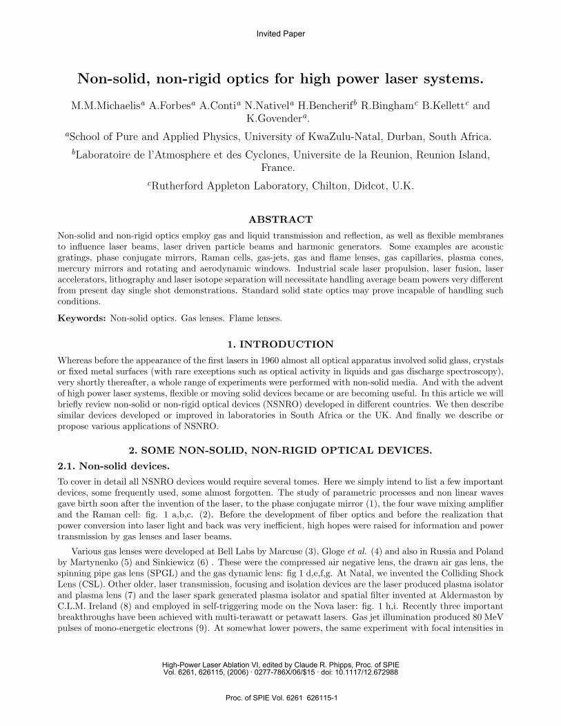
Figure 1. a. Raman cell converts pump power into other wavelengths. b. Self-pumped Phase Conjugate Mirror (PCM)corrects distortions introduced by e.g. laser amplifiers or the atmosphere. c. Four wave mixing amplification. d. Vortexof compressed air, negative lens. e. Drawn air gas lens. f. Spinning pipe gas lens (SPGL). g. Russian large aperture, gasdynamic lens. h. Laser produced plasma (LPP) isolator and plasma lens. i. Aldermaston spatial filter and LPP isolator.j. Irradiation of gas jets by petawatt laser pulses produces monoenergetic e-beams or soft X-rays. k. Conventionallyimploded µ-balloon is “fast-ignited” with gold cone focused PW laser. (In the future a shock-driven plasma-cone could beenvisaged). l. Lopes hollow pinch or self-drilled plasma waveguides for TW/PW lasers. m. Plasma Bragg Gating (PBG)for Chirped Pumped Amplifier (CPA) in PW systems. n. Plasma mirror removes pedestal portion of TW/PW pulse. o.Electronic liquid lenses for small aperture and ultra large aperture liquid mercury mirrors.
the 1013 W.cm−2 range yields high harmonics in the EUV spectral range. (10, 11). And a gold cone focused aGEKKO PW beam into a pre-compressed fusion target, demonstrating Tabak’s concept of Fast Fusion Ignition:fig. 1 j,k (12). Such gold cone ignition is inconceivable for a rep-rated power station. However, our collidingshock techniques described in section 3.3 might easily be adapted to generate PW focusing cones at repetitionrates of a few Hz.
In the context of laser accelerators, we think that attempts to generate plasma wave-guides will extend laseracceleration into the GeV range. One such wave-guide is the Lopes (13) or Hosokai (14) Z-pinch plasma channelgenerated between two disc electrodes: fig. 1 l. Two novel plasma devices are the plasma Bragg grating (15)and the plasma mirror (16): fig. 1 m,n. The former could serve to replace the extremely delicate and expensivegratings used for chirped pump amplification (CPA) central to PW lasers. The latter serves to remove the longpre-pulse or pedestal from ultra high power pulses, but might find many other applications, for instance in fusionand laser propulsion. Finally we mention two “liquid optics” devices. The liquid lens and the mercury mirror:fig. 1 o,p. Both these devices are becoming quite common in everyday optics and in amateur astronomy. Largeaperture mercury mirrors have only a small near-vertical field of view, but all-night automated data collection
Proc. of SPIE Vol. 6261 626115-2
c) AVCflflVI D)--tZ.bIES024—
0 fli-
IMD12LOIfLED
ElfOliL
biVill MVAE
VOL'l
1 )))
1V2 E If
AVC COWS ErEr VJIBBOB
IcCIB
-CPV
bIESO
VCOfl2.LIC CBV.LIWC
B)
2b0L2,HOL
)III
1V2 E If
BO.LV.LIIlC MIIIDOM
and multi-latitude operation can overcome this obvious difficulty. It isn’t hard to imagine the use of either ofthese two liquid optics varifocal devices with very high power lasers.
Figure 2. a. Acoustic grating. b. Rotating window for high average power transmission. c. Vacuum controlled adaptivevarifocal mirror focuses H-F or D-F laser on remote target. d. Piezo-controlled adaptive optics mirror compensateswave-front distortions in similar fashion to PCM.
2.2. Non-rigid devices
Here again we content ourselves with listing the devices in fig. 2, with a few words for each. The acoustic gratingwas the first “non-rigid” device used to split laser beams into separate channels: fig. 2a. Rotating mirrorsand windows are able to surmount the problems of thermal-lensing/mirror-deformation at high average beamirradiance: fig. 2b. Flexible vacuum controlled mirrors are used by the military to adjust their focal length forirradiation with kJ H-F or D-F pulsed lasers: fig. 2c. Most important of all are “adaptive optics” (AO) mirrorsdeveloped for “Star Wars” and later declassified for use in astronomy. They have recently been used to controlthe focusing of KrF lasers in a target area: fig. 2d(17). It is likely that “AO” will become a crucial feature oflaser propulsion of satellites: there is very little difference in focusing an energetic laser beam onto a militarytarget in space and doing the same for a laser propelled satellite.
3. NSNRO IN SOUTH AFRICA
We now describe NSNRO experiments carried out at the University of KwaZulu Natal in South Africa, some incollaboration with the National Laser Center (NLC) and RAL (UK).
3.1. The Spinning Pipe Gas Lens. (M. Notcutt, A. Prause)The Spinning Pipe Gas Lens (SPGL) was invented by Martynenko in 1985 at the Lyukov Institute of Heat andMass Transfer in Minsk, USSR. M. Notcutt (18) and one of us “re-invented” this lens three years later with noprior knowledge, due to difficulty in accessing Soviet literature. The SPGL is a thermal lens that overcomes the
Proc. of SPIE Vol. 6261 626115-3
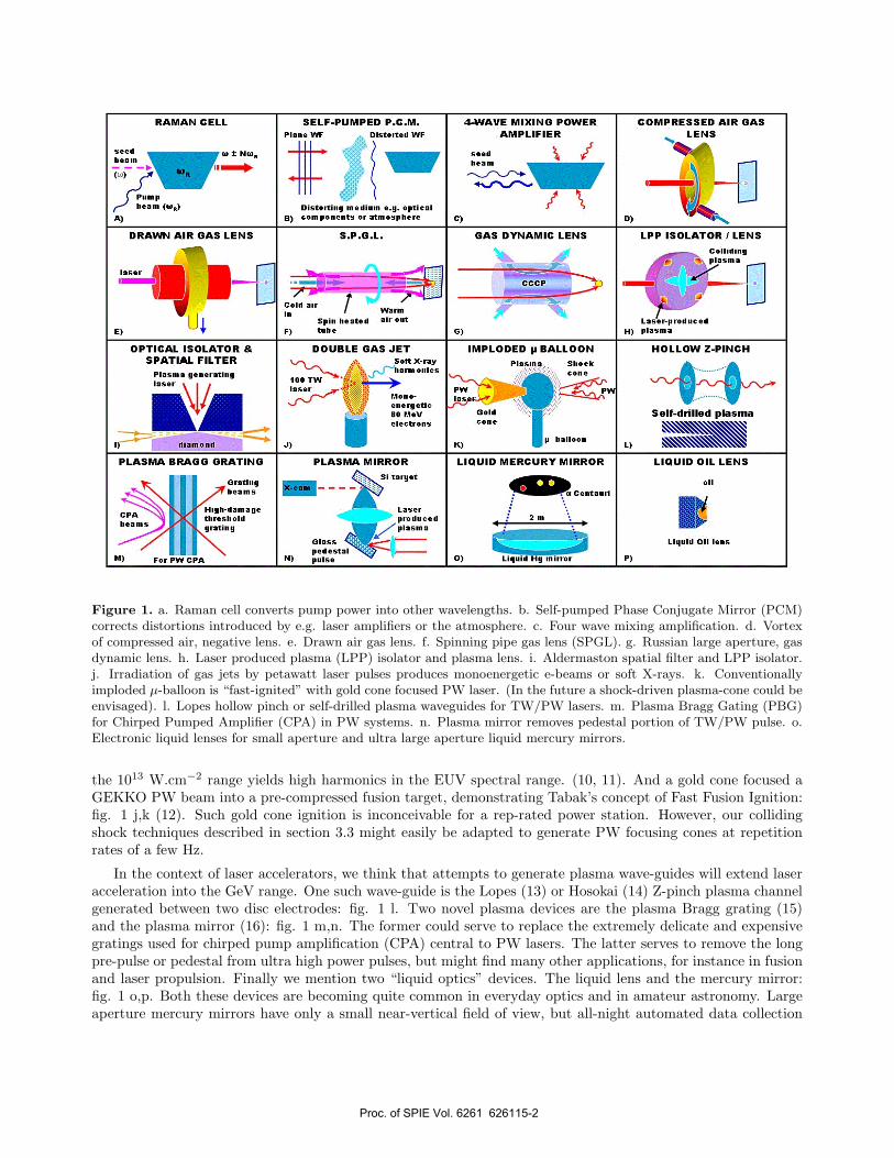
gravity induced limitations of the aspired lens by spinning the heated pipe. Each half of the SPGL is found tocontain three regions, which can be rendered visible with a spinning glass tube and smoke (19): fig. 3a. RegionI is cold air sucked along the axis. Region II is a stagnation volume of warm, slightly turbulent air. Region III isa warm sheath of counter-flowing air that gets centrifuged out of the ends. The corresponding temperatures areplotted in fig. 3b. We employed a SPGL to demonstrate the quality of gas lenses by imaging a water tower at adistance of 5 km, sunspots and various phases of the Moon: fig. 4 (20). The SPGL was one meter long, had aninternal diameter of 25 mm, was apertured down to about 8 mm and heated to a temperature of about 70oC.
Figure 3. The spinning pipe gas lens. a.The three separate regions of gas flow. b.Temperature profile measured inside aself feeding S.P.G.L.
3.2. The Colliding Shock Lens. (CSL). (R. Buccellato, N. Lisi, M. M.)
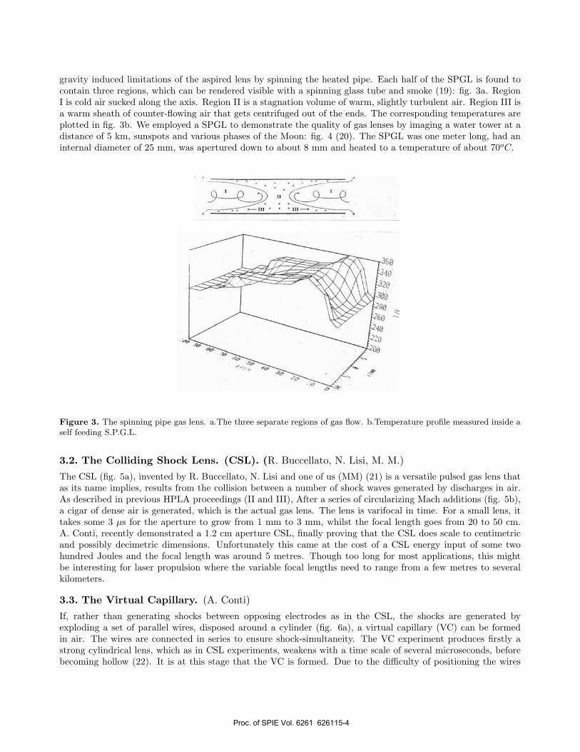
The CSL (fig. 5a), invented by R. Buccellato, N. Lisi and one of us (MM) (21) is a versatile pulsed gas lens thatas its name implies, results from the collision between a number of shock waves generated by discharges in air.As described in previous HPLA proceedings (II and III), After a series of circularizing Mach additions (fig. 5b),a cigar of dense air is generated, which is the actual gas lens. The lens is varifocal in time. For a small lens, ittakes some 3 µs for the aperture to grow from 1 mm to 3 mm, whilst the focal length goes from 20 to 50 cm.A. Conti, recently demonstrated a 1.2 cm aperture CSL, finally proving that the CSL does scale to centimetricand possibly decimetric dimensions. Unfortunately this came at the cost of a CSL energy input of some twohundred Joules and the focal length was around 5 metres. Though too long for most applications, this mightbe interesting for laser propulsion where the variable focal lengths need to range from a few metres to severalkilometers.
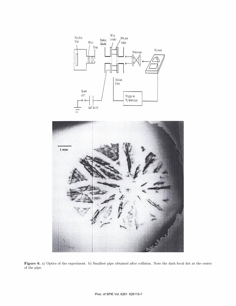
3.3. The Virtual Capillary. (A. Conti)
If, rather than generating shocks between opposing electrodes as in the CSL, the shocks are generated byexploding a set of parallel wires, disposed around a cylinder (fig. 6a), a virtual capillary (VC) can be formedin air. The wires are connected in series to ensure shock-simultaneity. The VC experiment produces firstly astrong cylindrical lens, which as in CSL experiments, weakens with a time scale of several microseconds, beforebecoming hollow (22). It is at this stage that the VC is formed. Due to the difficulty of positioning the wires
Proc. of SPIE Vol. 6261 626115-4
Figure 4. Water tower at 5 km, the Sun and Moon seen through a gas telescope.
with precision, only about 20 % of the implosions were satisfactory. However, we were able to demonstrate theformation of a sub-hundred micron diameter VC (Fig. 6b), which is what may be needed for laser accelerationexperiments - as described in section C. Greater reliability will be obtained by substituting sets of electrodes inseries for each wire. A new power supply, capable of producing the correct high voltage pulse is on order.
————-
3.4. Flame driven gas lenses. (N.Nativel)
The focal length of tubular gas lenses is given by the semi-empirical formula
f =104
6�r2 Tw
Tw − 300
where r is the radius of the lens, Tw is the wall temperature in absolute degrees and l is the length of thetube. This formula explains why gas lenses tend to be long narrow devices. In an attempt to remedy thisnegative aspect, we recently experimented with “flame lenses” in which flat oxyacetylene flames were injectedinto refractory or stainless steel cylinders (fig. 7a). (23). Although this method met with some success, the fociobtained were “fuzzy” due to turbulence and probably of little practical use. However, during our flame lensresearch, it happened that the flame was angled in the “wrong direction”: fig. 7b. As explained in our submittedarticle, this produced a remarkably good focus. The resulting lens we call a “flame driven lens”, since the flameonly serves to heat the stainless steel structure to a high temperature as well as to entrain air through the lensin several non-turbulent modes.
————-
Proc. of SPIE Vol. 6261 626115-5
toirI UJIIP
- -t - -
(rtTTT. I
ELECTRODES
LASER BEAM
GRINLENS
ARC
K-It
I.,• I
Figure 5. a) Device Geometry. b) Time sequence of CSL waves at times 3.2, 5, 6, 6.9, 8, 10, 10.4, 10.9, 11.3, 11.6, 11.8,12.2, 12.4, 13.1, 14 and 15.6 µs.
4. SOME APPLICATIONS OF NSNRO.
4.1. Laser Propulsion with NSNRO and Varifocal Beam Control.
Laser propulsion has so far only been demonstrated up to a height of some 30m. in the record breaking Myraboet al. experiments (24). For such low level flights, atmospheric absorption or distortion is hardly likely to beproblematic - especially as the “fuel” was air itself. The Myrabo et al. “light-craft” is designed so it couldaccommodate the hollow beam from an unstable resonator CO2 laser. Other “flyers” such as the Phipps etal. “Reference Flyer” (25) or the DLR Bohn and Schall bell shaped light-craft (26), may find Gaussian beamspreferable. In South Africa, our early (1997) successful >5m flights (27) were made possible by the use of the lowdivergence MLIS (molecular laser isotope separation) Gaussian beam. On attempting to repeat this experimentmore recently (2001) with a single one kilowatt oscillator (28), problems typical of future high altitude missionswere encountered: beam distortion and absorption prevented the one gram light-craft from rising higher thantwo meters. This was because the poor quality of the beam compelled us to focus the light within the launch
Proc. of SPIE Vol. 6261 626115-6
W 01)04< )lbILJCL (0
ppLI.
obucoj
1c1cocobo}4 jOWL
Figure 6. a) Optics of the experiment. b) Smallest pipe obtained after collision. Note the dark focal dot at the centerof the pipe.
Proc. of SPIE Vol. 6261 626115-7
bOVJ- EOCfl2
At2tBIE EVVJE
flVE EOCO2
Figure 7. a) Directly injected flame lens produces fuzzy focus. b) Flame driven lens generates sharp focus. (CourtesyOptics and Laser Technology).
tube and to use a highly absorbing “fuel”. (Without focusing and fuel change, the projectile failed to levitate).This focusing and fuel change resulted in combustion vapor-induced breakdown, once the craft had exceeded thefocal height. Similar problems with “flyer” exhaust interacting with multi-megawatt average power beams willwe believe, make varifocal beam control essential for “industrial scale” propulsion of the future. Many of theNSNRO lenses or mirrors described above could be useful. For centimetric beams either the CSL, the SPGL orthe novel flame driven lens could ensure that the flyer is never too far from the focal region.
If as is likely for beams of multi-megawatt average power, one will be dealing with meter scale apertures, then“AO” and/or flexible mirrors may be the only varifocal options. For vertical flights, mercury mirrors should beconsidered. Also the same PCM or Four Wave Mixing Amplifier tricks used in laser fusion might prove usefulin compensating for the atmospheric distortion of the beam. At the University of Natal, Cazalet et al. (29),demonstrated how a PCM could be used to remove the distortions of a gas lens. The disadvantage of using thismethod for laser propulsion is that because the optical path length through the atmosphere needs to be shortand because of the long o.p.l. in free space, the trajectory would need to be steep as well as linear. The lightcraftwould transmit a seed beam (similar to that envisaged in laser fusion) and would not be allowed to deviate fromthe amplified return beam which is fixed in space
4.2. Laser Fusion (LF).
LF is the one high power application where NSNRO has been routinely employed, namely in the aforementionedNova plasma isolator. NIF and “Laser Megajoule” may fire at most a few shots per day (not many less thanNova, Omega and GEKKO). Running a future LF power plant at several Hertz and average powers of severalMW will stress the optical components far beyond present day levels. Already the dimensions of petawatt andterawatt systems are determined by damage considerations. It is inevitable that lenses and mirrors that cannotbe damaged - such as the totally forgotten Russian gas dynamic lens (Fig. 1g) - will play an important role. AllLF plant designs address the problem of protecting the final focusing optics from debris. One popular conceptis to use a gas blanket system to absorb the debris as well as to exhaust the chamber after the TN detonation.(30). Configuring the blanket system as a gas lens would reduce the aperture of the final optics from ca 50 cm to10 cm and simultaneously remove the cost of periodically replacing damaged lenses or mirrors as well as reducethe radioactive waste.
4.3. Lithography and Virtual Capillaries (VC).
In order for the Moore’s Law prediction that the micro-electronic component density double every two years (31)be realized, ever shorter wavelengths for lithography are becoming essential. Two plasma based methods are at
Proc. of SPIE Vol. 6261 626115-8
the forefront of this industrial research. The first is laser produced plasma (LPP) as described in for instanceI.C.E. Turcu’s book on excimer LPP (32). The second is the now commercially available capillary or rotatingelectrode-pair discharge method, which generates EUV light at the mandatory 13.5 nm wavelength. The rep.rate of the commercial sources is a few tens of Hertz, the useful power ca. 20 W , and the mirrors are 90 %reflecting multilayer silicon-molybdenum. Debris mitigation is an important aspect and is accomplished with agaseous layer (not unlike future LF). Capillary EUV sources are only 1 cm to 1.5 cm long and can be operatedat kHz. rep. rates in a research environment. Commercial sources have a life-time of over 1000 hours. One of us(AC) has suggested that virtual capillaries should be studied in the Moore’s Law context: debris and life-timeproblems could be greatly reduced. We have demonstrated that the capillaries can be narrow enough. Yet toour knowledge, no laboratory has operated a VC so that it emits light, let alone under conditions similar to theEUV sources.
4.4. Laser Accelerators and Virtual Capillaries.
The “magic formula” for maximum laser acceleration energy versus electron density (9) is
E (eV ) =√
ne (cm)−3/2
This says that if multi-GeV beams are required for instance for manufacturing positron sources for PET(positron emission tomography), then acceleration lengths of tens of centimeters will be needed and high plasmadensities (ne ≈ 1020 cm−3). This demands some form of high density laser wave-guiding through narrow channels.As with lithography, whilst pre-excited capillary wave-guiding works well for a limited number of shots, this isonly a useful method for proof of principle demonstrations. It may not be easy as our preliminary VC experimentstaught us, to produce a reliable high rep-rate sub-millimetric VC. But it will be equally difficult to imagine multi-staging and synchronizing air jet petawatt laser acceleration regions, not to mention “getting the phase right”.This may involve gas jet positioning with sub-micron precision. In the event of the phase adjustment problemproving insuperable, it may be better to opt for the longer interaction lengths provided by plasma pinches,self drilled plasmas or VC’s. This may also require a different acceleration mechanism such as Beat WaveAcceleration. In this context we mention an unusual feature of virtual capillaries, namely that their transverseand longitudinal geometry is easily modified. By exploding only four wires we have already demonstrated a VCwith rectangular cross section (22). It would be a trivial modification for the spark gap driven VC to generatea VC light pipe that follows a circular trajectory. Coupled with an adjustable magnetic field, this would enable“optical cyclotron” (or “cycloptron”) experiments to be conducted. The prototype optical cyclotron could be ofsimilar size to E.O.Lawrence’s first ever device which only generated 50 MeV electrons. If the cyclotron radiusr � 20 cm and the VC radius is 100 µm then for the circular light guide we write for the arc length
l = r.∆θ
and
∆θ = l∆n
∆r
so
∆n
∆r=
1r
or ∆n =∆rr
≈ 5.10−4
Since
n ≈ 1 − 12
ne
nc
And for 1 µm light nc ≈ 1021 cm−3 we require ne ≈ 1018 cm−3, an easily achievable light pipe requirement.
Proc. of SPIE Vol. 6261 626115-9
BE
AM
RA
DIU
S (m
m)
U 5 20 25 3010 15
TIME (s)
4.5. High power laser beam delivery for Laser Isotope Separation (AVLIS and MLIS):rotating and aerodynamic windows.
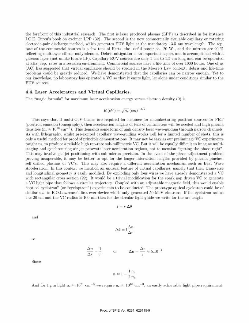
Uranium, though probably the most important IS material is not the only material of interest. Presently thereis great importance attached to growing pure carbon 12 diamond for semi-conductor manufacture (19) becauseof its very high thermal conductivity. (Absence of phonon scattering). But whatever the material, whatever thelaser, very long thin high intensity beams will probably be required for industrial scale operation. This meansthat the optics will need to be able to withstand average powers in the kilowatt/cm2 range. Thermal lensing intransmission optics is well known and well documented in the literature. In high power laser systems such asthe Pelindaba CO2 MLIS chain, this thermal lensing leads to rapid changes in the measured beam parametersobserved at the amplifier chain output. An example of this is shown in fig. 8 where the beam radius is observed torapidly decrease with time as the thermal lens develops. Such rapid laser beam changes can result in catastrophicdamage to optical elements further down the path, create non-linear effects such as self-focusing, or generateplasmas in air. These influences are undesirable when trying to deliver high average power laser beams. Thereare two types of window that can mitigate the effects of thermal lensing: the rotating and the aerodynamicwindow. The rotating window is a device in which the optical window is rotated off axis, causing the beam toheat a different part of the window with each pulse. Care needs to be taken to achieve maximum heat dissipation.For example, if the rotation period matches the time between pulses, the window appears stationary. At thecorrect rate of rotation, the heating is spread over a large area thus reducing the temperature gradient. Fig. 9shows how significant reduction of thermal lensing was achieved in one of the MLIS amplifiers.
Figure 8. Change of laser beam radius in the MLIS, MOPA chain. Stability is reached after approx 20s.
The aerodynamic window seeks to remove lensing by virtue of the absorption coefficient of gas being muchlower than that of a solid state device. It uses flowing gas to act as a window: with the correct pressure gradientsalong the flow direction, the system acts as a barrier to the atmosphere. In our experiments, the flow of gas wasparallel to the laser beam propagation direction, though in other designs transverse flow is employed. In thisexperiment , the last amplifier in the laser chain had both conventional windows removed and replaced with a
Proc. of SPIE Vol. 6261 626115-10
(mm
) C
o
C/)°lDI0 I. 11.1 l ROTAT
0 1 2 3
STATIONARY WINDOW
ING WINDOW
TIME (s)
Figure 9. Significant reduction in thermal lensing achieved with a rotating window.
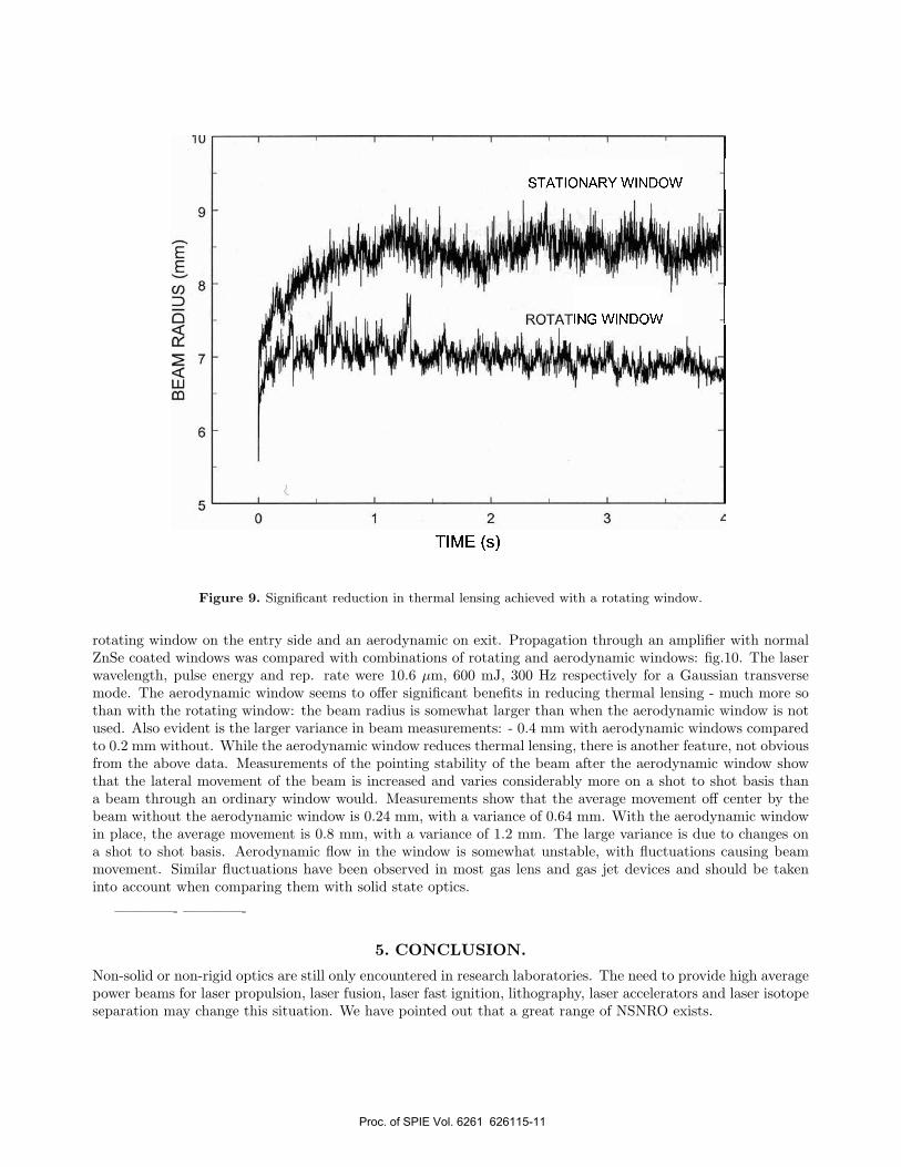
rotating window on the entry side and an aerodynamic on exit. Propagation through an amplifier with normalZnSe coated windows was compared with combinations of rotating and aerodynamic windows: fig.10. The laserwavelength, pulse energy and rep. rate were 10.6 µm, 600 mJ, 300 Hz respectively for a Gaussian transversemode. The aerodynamic window seems to offer significant benefits in reducing thermal lensing - much more sothan with the rotating window: the beam radius is somewhat larger than when the aerodynamic window is notused. Also evident is the larger variance in beam measurements: - 0.4 mm with aerodynamic windows comparedto 0.2 mm without. While the aerodynamic window reduces thermal lensing, there is another feature, not obviousfrom the above data. Measurements of the pointing stability of the beam after the aerodynamic window showthat the lateral movement of the beam is increased and varies considerably more on a shot to shot basis thana beam through an ordinary window would. Measurements show that the average movement off center by thebeam without the aerodynamic window is 0.24 mm, with a variance of 0.64 mm. With the aerodynamic windowin place, the average movement is 0.8 mm, with a variance of 1.2 mm. The large variance is due to changes ona shot to shot basis. Aerodynamic flow in the window is somewhat unstable, with fluctuations causing beammovement. Similar fluctuations have been observed in most gas lens and gas jet devices and should be takeninto account when comparing them with solid state optics.
————- ————-
5. CONCLUSION.
Non-solid or non-rigid optics are still only encountered in research laboratories. The need to provide high averagepower beams for laser propulsion, laser fusion, laser fast ignition, lithography, laser accelerators and laser isotopeseparation may change this situation. We have pointed out that a great range of NSNRO exists.
Figure 10. Beam radius for various window combinations.
REFERENCES1. R. Hellwarth, 1977. J.Opt.Soc.Am., 67, 1.2. A. Yariv, 2000. IEEE Sel. Topics in Q. Electron., 1478.3. D. Marcuse, 1982. “Light Transmission Optics”. Van Nostrand. NY.4. D. Gloge, 1968. “Deformation of Gas Lenses by Gravity”. Bell Syst. Techn. J.4, 7, p. 179.5. O. G. Martynenko, N. I. Lemesh. Il Nuovo Cimento, 5D (1985), 225.6. E. Sinkiewicz, 1981. Optica Applicata, 11, p. 243.7. P. T. Rumsby, M. M. Michaelis, 1977. Opt. Comm., 21, 337.8. C. L. M. Ireland, 1980. J.Phys.D: Appl.Phys., 13, 9.9. R. Bingham, J. T. Mendonca, P. K. Shukla, 2004. Plasma Phys. & Contr. Fusion. 46, R1.10. S. Banerjee et al., 2003. J.Opt.Soc.Am. B., 20, 182.11. H. Fiedorowicz, 2005. Laser and Part.Beams, 23, 365.12. P. A. Norreys et al., 2003. 3rd Int.Conf. on Inertial Fusion Sci & Applics. 13.13. N. Lopes, 2004. CARE-ELAN 2004-017. “Adv and Novel Accelerator Development”. GoLP Presentation
A10.14. T. Hosokai et al., 2003. Phys Rev E.67.036407. (See also JAERI website).15. H.-C. Wu et al., 2005. Laser and Part.Beams, 23, 417.16. H. C. Kapteyn et al., 1991. Opt.Lett., 16, 490.17. M. J. Shaw et al., 1986. J.Opt.Soc.Am.B., 10. 1466.18. M. Notcutt, 1989. “Gas Lenses”. Ph.D. thesis, University of Natal, South Africa.19. A. R. Prause, 1994. “Applications of Optical, Plasma and Laser Focusing”. Ph.D. thesis, University of Natal,
South Africa.
Proc. of SPIE Vol. 6261 626115-12
20. M. M. Michaelis et al., 1991. Nature, 353, 547.21. R. Buccelato, N. Lisi and M. M. Michaelis, 1993. Opt. Comm., 101, 350.22. A.Conti. 2004. “Gas and Plasma Structures”. Ph.D. thesis, University of KwaZulu-Natal, South Africa.23. M. M. Michaelis and N. Nativel, 2006. Optics and Laser Technology, submitted.24. L.N. Myrabo, 1987. SDIO Workshop on Laser Propulsion. P 173-208.25. C. R. Phipps, J. P. Reilly, J. W. Campbell, 2000. Laser and Part. Beams, 661.26. W. O. Schall, W. L. Bohn, H. A. Eckel, W. Mayerhofer, W. Riede, E. Zeyfang. HPLA III. Proc. SPIE, 4065,
472.27. M. M. Michaelis et al., HPLAIV. Proc. SPIE, 4760, 691.28. M. M. Michaelis and A.Forbes, 2006. Submited to S.A.J. Sci.29. R. S. Cazalet, P. F. Cunningham et al., 1990. Sci. Tech. (J.Phys.E), 1, 147.30. N. G. Basov, I. G. Lebo, V. B. Rozanov. ”The Physics of Laser Thermonuclear Synthesis” in Russian.
(Translation available).31. H.Wong, H,Iwai. 2005. Physics World. Sept. 40.32. I. C. E.T urcu. 1996. “Generation & Application of X-Rays from excimer’s”. D.Phil thesis. London.