JOURNAL OF RESEARCH of the National Bureau of Standards Vol. 87, No. 5, September-October1982 Nondestructive Evaluation Methods for Quality Acceptance of Installed Building Materials James R. Clifton* and Nicholas J. Carino* National Bureau of Standards, Washington, DC 20234 July 29, 1982 A review of methods developed for the nondestructive evaluation (NDE) of building materials is presented. The generic features of NDE methods are discussed. This is followed by descriptions of specific methods. The principles underlying the operation of the methods are described, along with their typical ap- plications, advantages, and limitations. A table is included summarizing the characteristics of various NDE methods. Key words: building materials; concrete; evaluation; inspection; inplace testing; nondestructive testing; quality assurance. INTRODUCTION A nondestructive evaluation (NDE) method refers to a procedure for obtaining information about the properties of an object without altering that object, and contrasts with traditional destructive tests which permanently damage test objects. Another significant characteristic of many NDE methods is that they are capable of perform- ing measurements not only on laboratory specimens but also on objects "in-situ." It is the latter attribute which makes NDE methods extremely valuable in the area of building technology. With today's emphasis on rehabilitation and renovation, as opposed to new con- struction, there is a need for methods to evaluate the con- dition of existing structures. Such an assessment is re- quired in order to develop the best renovation scheme. In addition, NDE methods are valuable tools for periodic inspections of structural components to determine the degree of deterioration, if any, which may occur during service conditions. Finally, these methods may be used for quality assurance purposes to determine whether or not an item has been fabricated as intended. The pur- pose of this article is to review the NDE methods which have been developed for the examination of materials and structural components. NDE methods typically measure the properties that are desired in an indirect manner, that is, they measure a characteristic which is somehow related to the property in question. Thus, the accuracy of property measurements based on NDE methods will depend on several factors. First, it will depend on the relationship between the desired property and the quantity actually *Center for BuildingTechnology, National Measurement Laboratory. measured by the NDE method. If the relationship is strong, then the property can be estimated quite ac- curately by means of the indirect measurement. Second, the accuracy will depend on how insensitive the indirect measurement is to factors which do not affect the prop- erty in question. For example, if an NDE method is used to estimate the strength of a material and if the NDE measurement is strongly influenced by the moisture con- tent while strength is not, then the strength estimate will be imprecise unless corrections are made for the actual moisture content. Finally, the accuracy will depend on the precision of the NDE measurement. Thus, prior to employing an NDE method, the user must be fully aware of the principles and limitations inherent to the method. Otherwise, incorrect interpretations will result. The material property of most interest in engineering applications is strength. NDE methods may be used to determine the strength of materials as well as to deter- mine whether or not flaws are present in the material which have an adverse effect on its strength. Some of the indirect measurements used to estimate the desired prop- erties include the velocity of ultrasonic waves through the material, the disturbances of magnetic fields by discontinuities in the material and the absorption of electromagnetic radiation, such as x-rays. Because of great differences between the properties of metallic and non-metallic building materials, many of the NDE methods are not applicable to both classes of materials. Steel, concrete and wood are the main structural materials, but the technology of nondestructive evalua- tion is not equally developed for all three types of materials. The most technically advanced methods are for steel inspection, which is in part due to the com- 407
Transcript
JOURNAL OF RESEARCH of the National Bureau of StandardsVol. 87, No. 5, September-October 1982
Nondestructive Evaluation Methods forQuality Acceptance of Installed Building Materials
James R. Clifton* and Nicholas J. Carino*
National Bureau of Standards, Washington, DC 20234
July 29, 1982
A review of methods developed for the nondestructive evaluation (NDE) of building materials ispresented. The generic features of NDE methods are discussed. This is followed by descriptions of specificmethods. The principles underlying the operation of the methods are described, along with their typical ap-plications, advantages, and limitations. A table is included summarizing the characteristics of variousNDE methods.
A nondestructive evaluation (NDE) method refers to aprocedure for obtaining information about the propertiesof an object without altering that object, and contrastswith traditional destructive tests which permanentlydamage test objects. Another significant characteristic ofmany NDE methods is that they are capable of perform-ing measurements not only on laboratory specimens butalso on objects "in-situ." It is the latter attribute whichmakes NDE methods extremely valuable in the area ofbuilding technology. With today's emphasis onrehabilitation and renovation, as opposed to new con-struction, there is a need for methods to evaluate the con-dition of existing structures. Such an assessment is re-quired in order to develop the best renovation scheme. Inaddition, NDE methods are valuable tools for periodicinspections of structural components to determine thedegree of deterioration, if any, which may occur duringservice conditions. Finally, these methods may be usedfor quality assurance purposes to determine whether ornot an item has been fabricated as intended. The pur-pose of this article is to review the NDE methods whichhave been developed for the examination of materialsand structural components.
NDE methods typically measure the properties thatare desired in an indirect manner, that is, they measure acharacteristic which is somehow related to the propertyin question. Thus, the accuracy of propertymeasurements based on NDE methods will depend onseveral factors. First, it will depend on the relationshipbetween the desired property and the quantity actually
*Center for Building Technology, National Measurement Laboratory.
measured by the NDE method. If the relationship isstrong, then the property can be estimated quite ac-curately by means of the indirect measurement. Second,the accuracy will depend on how insensitive the indirectmeasurement is to factors which do not affect the prop-erty in question. For example, if an NDE method is usedto estimate the strength of a material and if the NDEmeasurement is strongly influenced by the moisture con-tent while strength is not, then the strength estimate willbe imprecise unless corrections are made for the actualmoisture content. Finally, the accuracy will depend onthe precision of the NDE measurement. Thus, prior toemploying an NDE method, the user must be fullyaware of the principles and limitations inherent to themethod. Otherwise, incorrect interpretations will result.
The material property of most interest in engineeringapplications is strength. NDE methods may be used todetermine the strength of materials as well as to deter-mine whether or not flaws are present in the materialwhich have an adverse effect on its strength. Some of theindirect measurements used to estimate the desired prop-erties include the velocity of ultrasonic waves throughthe material, the disturbances of magnetic fields bydiscontinuities in the material and the absorption ofelectromagnetic radiation, such as x-rays. Because ofgreat differences between the properties of metallic andnon-metallic building materials, many of the NDEmethods are not applicable to both classes of materials.
Steel, concrete and wood are the main structuralmaterials, but the technology of nondestructive evalua-tion is not equally developed for all three types ofmaterials. The most technically advanced methods arefor steel inspection, which is in part due to the com-
407
paratively homogenous nature of steel compared to theother materials. Concrete is unique among constructionmaterials in that it is manufactured on-site (or at anearby concrete plant) using locally available materials.Thus, there is no such thing as a "grade" concrete whichhas well-defined physical and chemical propertiesanalogous to a "grade" of steel. In addition, concrete is amacroscopically heterogenous material composed of ce-ment, water, sand and rocks. For these reasons, NDEmethods have been developed for specific application toconcrete, and as will be explained some are not com-pletely "nondestructive." The technology of NDE in-spection is least developed for wood.
A key element of many NDE methods is the calibra-tion standard or calibration curve which is necessary totranslate the indirect measurement to an estimate of thedesired property. The development of the calibrationprocedure is just as important as the development of thehardware for performing the indirect measurement, andthis must be kept in mind when choosing among alter-native methods for estimating a desired property. The"cost" of NDE inspection involves not only the cost ofthe apparatus but also the cost of the calibration. For ex-ample, many of the methods used for concrete inspectionemploy relatively inexpensive test apparatus, but theirimplementation requires laboratory testing to developthe applicable calibration curve. The need for calibra-tion will be mentioned as each method is discussed.
Having presented this brief introduction to some ofthe generic characteristics of NDE methods, we will nextdiscuss the principles, applications, advantages anddisadvantages of methods which are felt to be applicablefor the inspection of building materials and structuralcomponents. The methods are presented in alphabeticalorder beginning with acoustic methods and ending withvisual inspection. A special section details a proposedprocedure which combines two of the other methods forthe purpose of improving the accuracy of strengthprediction of concrete. Following this section, the utilityof the various NDE methods is discussed in the Sum-mary. Also, displayed in table form for the reader's con-venience, is information on commonly used NDEmethods, which should prove useful in selecting an NDEmethod for a specific application.
DESCRIPTION OF NDE METHODS
1. Acoustic Emission Method
In this method, stress waves originating from withinthe test material or object are detected using surfacetransducers. [11].1 The acoustic waves are due to the sud-
]Figures in brackets indicate literature references at the end of this paper.
den release of stored strain energy when either pre-existing or newly created flaws propogate under the ac-tion of an applied stress field. The types of flaw propaga-tion that can be detected include dislocation movementin metals and crack growth in metals or brittle solidssuch as concrete. Thus, acoustic emission is able to deter-mine the onset of mechanical failure, i.e., yielding orfracture. The test object needs to be stressed so that crea-tion, movement, or propogation of flaws will occur.Static flaws are not detected by acoustic emission.
1.1. Description of Method
Acoustic emission testing is a passive technique andonly an acoustic wave detection instrument is required.The acoustic waves, which may have a frequency rangefrom audible to ultrasonic, are detected by piezoelectrictransducers attached to the surface of the test object.Flaw growth usually can be detected by a transducerlocated on the test object some distance from the flawregion (provided that the wave amplitude is sufficient tobe detected). The transducers generally detect waves inthe frequency range of 50 kHz to 10 MHz [1]. Detectedsignals are amplified and the amount of amplificationdepends on the source of the acoustic emission; signalsfrom dislocation movement require greater amplificationthan signals from microcrack propagation. Afteramplification, the acoustic emission activity is processedand displayed. The most useful data are the rate ofacoustic emission events and the cumulative number ofevents plotted as a function of time, applied load ornumber of load cycles.
1.2. Applications
The method has been used to monitor the in-servicebehavior of pressure vessels (including nuclear reactors),to detect the onset of rapid crack propagation underfatigue loading or due to stress corrosion, and to monitorthe response of systems to proof-load tests. Becauseacoustic emissions give forewarning of ultimate failure,the technique can be used to indicate when loads shouldbe reduced to prevent total failure. By using multiplepickup of acoustic signals with transducers at differentlocations and by electronic data processing, it is possibleto pinpoint regions of high acoustic emission activity andthereby locate the area of law development or propaga-tion.
1.3. Advantages and Limitations
The most significant advantage of the acoustic emis-sion method is that it gives the response of the total struc-
408
ture (or system) to applied loads. By observing theacoustic emission activity as loads are applied it is possi-ble to monitor the rate of internal material deteriorationtaking place (yielding or fracture) as a function of load.It is generally possible to determine the stage of incipientfailure as this is usually accompanied by a rise in theacoustic emission rate and rapid increase in thecumulative number of emissions.
A major difficulty in interpreting acoustic emissionresults is the separation of signals due to the loadingsystem or microscopic slippage at joints in the test objectfrom the signals due to flaw propagation in the material.Users of the technique must be aware of all the possibleextraneous acoustic signals that may be detected by thetransducers, and must take precautions not to confusethem with signals due to flaw growth. Some backgroundnoise may be eliminated by using low frequency filters,but usually it is necessary to properly plan an acousticemission inspection to eliminate unwanted noises.Equipment costs vary from moderate ($10,000) to veryexpensive depending on whether a single- or multiple-pickup system is required for the particular application.
2. Acoustic Impact Method
2.1. Description of Method
Acoustic impact is the oldest and simplest form ofacoustic inspection. In this method, audible stress wavesare set up in a test object by mechanical impact and thefrequency and damping characteristics of the vibrationscan be used to infer the integrity of the test object [2]. Inits most unsophisticated form, the test object is struckwith a hammer and the operator listens to the "ringing"(which is due to resonant vibration of the object). In amore sophisticated form, a transducer is attached to thetest object, and an amplifier and display unit are used toproduce a visual display of the frequency and dampingcharacteristics of the "ringing". By comparing the out-put with a standard of acceptable quality, a decision ismade regarding the integrity of the object.
2.2. Applications
This method can be used to detect hollow zones anddelaminations in concrete and masonry structures or itmay be used to detect the location of studs behindwallboard. It also has been used to detect deliminationsin laminar and composite materials and rot in wood. Bymeasuring the transmission time in wood, it's modulus ofelasticity can be determined.
2.3. Advantages and Limitations
The equipment required to carry out the test isrelatively inexpensive and the test can be performed easi-ly. However, because the "ringing" can be affected bythe mass and geometry of the test object, an experiencedoperator may be needed to correctly interpret the results.
3. Cast-In-Place Pullout
The pullout test measures the force required to pullout a steel insert, having an enlarged end, which hasbeen cast in concrete (fig. 1). The concrete is subject to acomplex state of stresses by the pullout force, and a coneof concrete is removed at failure. The pullout forces areusually related to the compressive strength of the con-crete, with the ratio of pullout strength (force divided bysurface area of the conic frustum) to compressivestrength being in the range of 0.1 to 0.3. Correlationgraphs are used to relate pullout force to compressivestrength. There are several commmercially available testapparatus for measuring the pullout resistance of con-crete with prices varying from $1000 to $6000.
ADRAW ROD
\ c~0 P
-; ,) \4I- , a to ,
REACTIONJ, RING
I,
0 i , O -,, I
Jo' CONCRETEo H t. / /o / / , L
ca o t t
FIGURE 1. Schematic of cast-in-place pullout device.
3.1. Description of Method
The American Society for Testing and Materials4ASTM) has recently issued a test method, C900 [3]which describes the pullout assembly and givesallowable dimensions. The pullout insert is cast-in-placeduring placing of fresh concrete, and it is either pulledcompletely out of the concrete, or pulled until maximumload is reached, with a manually operated hollow tensionram exerting pressure through the steel reaction ring.Components of one possible test apparatus for pulling
409
out the insert are shown in figure 2.2 Testing andcalculation procedures are also given in ASTM C900.Techniques have been developed so that the inserts canbe embedded deep in concrete, thereby permittingtesting of the interior concrete.
FIGURE 2. Components of one Type of apparatus for performingpullout test.
Because the pullout insert is usually cast-in-place dur-ing placing of the fresh concrete, these tests must beplanned in advance. Alternatively, hardened concretecan be drilled to receive the pullout insert. This nec-cesitates drilling through the bottom or backside of aconcrete slab for example, to the proper depth and widthto permit the insertion of the enlarged head. A smallerhole, sufficient to permit insertion of the steel shaft, isdrilled through the remaining portion of the concreteslab, the insert is placed through the bottom or backside,and the test is performed. This alternate method is cur-rently being developed and is not covered by ASTMC900.
3.2. Reliability of Method
Malhotra [41 and Richards [5] have shown the pulloutmethod is a reliable method for estimating the com-pressive strength of concrete. Malhotra found that thecoefficients of variation for pullout test results were inthe same range as those obtained from testing standardcylinders in compression. Correlation coefficients of 0.97to 0.99 have been obtained for normal weight concretefrom curve fitting of pullout and compression testresults.
21n this paper several commercially available devices used for NDE teats of
building materials are identified and discussed. Such identification does notimply recommendation or endorsement by the National Bureau of Standards.
3.3. Advantages and Limitations
The pullout technique is the only nondestructive testmethod which directly measures a strength property ofconcrete in place. The measured strength is thought tobe a combination of tensile and shear strengths.
The major disadvantage of the pullout test is that acone of concrete is sometimes pulled out necessitatingminor repairs. However, if the pullout force is quicklyreleased when failure is just initiated, the concrete conewill not be torn loose, and no repairs will be required.Another disadvantage is the need to plan where insertsare to be located and to make provisions for their place-ment prior to placing concrete. The feasibility of drillingholes into hardened concrete and inserting pulloutdevices is being explored [61. This would eliminate theneed to install the inserts prior to placing concrete.
4. Electrical Potential Measurements
Information on the corrosion state of metals can be ob-tained from measuring the electrical potential of themetal using a standard reference electrode and avoltmeter. As the electrical potential of a metal becomesmore negative, the probability that corrosion has takenplace increases.
4.1. Measurements on Steel in Concrete
The electrical potential method is commonly used toassess the corrosion condition of steel reinforcement inconcrete. The electrical potentials of steel reinforcementare measured by making an electrical connection from avoltmeter to the reinforcement and a second electricalconnection from the voltmeter to a reference cell inphysical contact with the surface of the concrete (fig. 3).Dry concrete must be moistened before making electricalmeasurements. A saturated copper-copper sulfate elec-trode is usually used as the reference cell. The electricalpotential of the reinforcement located below thereference cell is measured.
VOLTMETER
SATURATED Cu/CuSO4ELECTRODE
:J , :S , i X .
REINFORCINGSTEEL7
CONCRETE -_ a ') /I /Z/,l )#A'
FIGURE 3. Measurement of electrical potential of steel reinforcing
bars in concrete.
410
.��7�;.;4 I . .:�,I,L .
If the electrical potential of the steel reinforcement ismore negative than -0.35 V versus the copper sulfateelectrode, active corrosion is probably taking place.Values in the range of -0.30 to -0.35 V suggest that cor-rosive conditions are developing at the concrete-steel in-terface, while values less negative than -0.30 V indicatethat the steel is probably passive, i.e., not corroding 17].
An electrical potential diagram of a concrete slab canbe constructed in which areas of similar potentials areoutlined. This can be used to identify those areas wherereinforcement may be corroding.
4.2. Advantages and Limitations of Method
The equipment is inexpensive and only a moderateamount of user expertise is needed to make themeasurements. Measurements of the electrical potentialof steel reinforcement provide information concerningthe probability for the occurrence of corrosion. However,information on either the rate or the extent of corrosionis not obtained. In addition, a direct electrical connec-tion must be made to the reinforcing steel. If the steel isnot exposed, then some concrete covering must beremoved.
5. Electro-Magnetic Methods
The presence of flaws or changes in composition ofmetals will affect their electrical and magnetic proper-ties. Therefore, it is possible to detect anomalies inmetals by measuring changes in the electrical andmagnetic characteristics of metals. NDE methods thatfunction on the above basis include eddy current,magneto-inductive, and magnetic particle testing.
5.1. Eddy Current Inspection
Eddy current inspection is a versatile NDE methodbased upon the principles of electromagnetic inductionand is only applicable to inspection of metals [11.
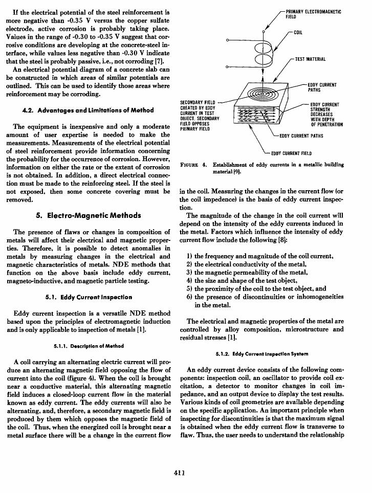
SECONDARY FIELD -CREATED BY EDDY ICURRENT IN TEST g ark X VI,-OBJECT. SECONDARY 7 &e A vFIELD OPPOSES - "PRIMARY FIELD
FIGURE 4. Establishment of eddymaterial 19].
PRIMARY ELECTROMAGNETICFIELD
COIL
TEST MATERIAL
EDDY CURRENTPATHS
EDDY CURRENTSTRENGTH
V/ ZDECREASESWITH DEPTH
w_:tff OF PENETRATION
\EDDY CURRENT PATHS
-EDDY CURRENT FIELD
currents in a metallic building
in the coil. Measuring the changes in the current flow (orthe coil impedence) is the basis of eddy current inspec-tion.
The magnitude of the change in the coil current willdepend on the intensity of the eddy currents induced inthe metal. Factors which influence the intensity of eddycurrent flow include the following [8]:
1) the frequency and magnitude of the coil current,2) the electrical conductivity of the metal,3) the magnetic permeability of the metal,4) the size and shape of the test object,5) the proximity of the coil to the test object, and6) the presence of discontinuities or inhomogeneities
in the metal.
The electrical and magnetic properties of the metal arecontrolled by alloy composition, microstructure andresidual stresses [1].
5.1.1. Description of Method
A coil carrying an alternating electric current will pro-duce an alternating magnetic field opposing the flow ofcurrent into the coil (figure 4). When the coil is broughtnear a conductive material, this alternating magneticfield induces a closed-loop current flow in the materialknown as eddy current. The eddy currents will also bealternating, and, therefore, a secondary magnetic field isproduced by them which opposes the magnetic field ofthe coil. Thus, when the energized coil is brought near ametal surface there will be a change in the current flow
5.1.2. Eddy Current Inspection System
An eddy current device consists of the following com-ponents: inspection coil, an oscillator to provide coil ex-citation, a detector to monitor changes in coil im-pedance, and an output device to display the test results.Various kinds of coil geometries are available dependingon the specific application. An important principle wheninspecting for discontinuities is that the maximum signalis obtained when the eddy current flow is transverse toflaw. Thus, the user needs to understand the relationship
411
between coil configuration, eddy current flow and typeof flaw to be detected.
The frequency of the excitation current affects thedepth of the eddy currents and the sensitivity of flawdetection. Increasing the coil frequency will reducepenetration but increase sensitivity. Thus high coil fre-quencies should be used in attempting to detect smallnear-surface flaws. If it is desired to detect sub-surfaceflaws, a lower frequency should be used but theminimum detectable flaw size increases. Thus, there is atrade-off of penetrating ability versus sensitivity which iscommon to other inspection methods. The range of fre-quencies is from 200 Hz to 6 MHz [1], with the lowerfrequencies used primarily for inspecting ferromagneticmetals.
The detector circuit can also take on many formsdepending on the application of the instrument. In anycase, the changes in coil impedance that occur during in-spection are small and bridge circuitry, similar to thatused to monitor electrical resistance strain gages, is usedto detect these changes. In making a measurement, theimpedance bridge is first balanced by using an internaladjustment or placing the coil on a reference object of ac-ceptable quality; then the coil is placed on the test object,and any difference between test object and reference ob-ject will result in an imbalance of the bridge which is in-dicated on the output device. The output device can beof many forms, such as audible alarms, meters, X-Y plot-ters, strip-chart recorders, magnetic tape, storageoscilloscopes, or a computer.
5.1.3. Instrument Calibration
Because there are many factors that may affect thecoil impedance when a test is performed, the object usedto calibrate the instrument must be carefully chosen. Forexample, to detect cracks, the reference object must havethe same electrical and magnetic properties as the testobject; otherwise differences in alloy composition couldbe interpreted as a crack. Therefore, a user must beknowledgeable in the operation of an eddy currentdevice in order to properly calibrate it and to interprettest results.
5.1.4. Applications
Eddy current inspection has many uses including thedetection of flaws such as cracks, porosity, or inclusionsin metals; detection of changes in alloy composition ormicrostructure; and the measurement of the thickness ofnonconductive coatings on a metal.
5.1.5. Advantages and LImitations
There are several important limitations to eddy cur-rent inspection. A major limitation is the depth at whichdiscontinuities can be detected. The density of eddy cur-rents rapidly decreases with increased distances belowthe surface of a metal. The depth of penetration is con-trolled by the resistivity and permeability of the metaland the coil frequency.
The strength of the signal due to a particular defectwill depend on the proximity of the coil to the surface ofthe test object. As this distance, called "lift-off," in-creases the signal strength diminishes. The lift-off effectis so strong that it may mask signal changes due todefects. Care must be taken, therefore, to ensure uniformcontact between coil and test object. This requirementmay make it difficult to test objects with rough or ir-regular surface. The lift-off effect may be used, however,in measuring the thickness of nonconductive coatings ona conductive metals or non-magnetic metal coatings onmagnetic metals. Proper calibration samples are re-quired to use an eddy current instrument as a thicknessgage.
5.2. Magneto-Inductive Methods
This technique is only applicable to ferromagneticmetals and is primarily used to distinguish between steelof different alloy composition and different heattreatments. The principle involved is electromagnetic in-duction and the equipment circuitry resembles a simpletransformer in which the test object acts as the "core"[1]. There is a primary coil connected to a power supplydelivering a low frequency (10 to 50 Hz) altering current,and a secondary coil feeding into an amplifier circuit. Inthe absence of a test object, the primary coil induces asmall voltage in the secondary coil, but when a fer-romagnetic object is introduced a much higher secon-dary voltage is induced. The magnitude of the inducedvoltage in the secondary coil is a function of themagnitization characteristics of the object, and changesin these characteristics are used to distinguish betweensamples of different properties. As in the case of eddycurrent inspection, this method can be used for quan-titative measurement only after proper calibration is per-formed.
5.3. Cover Meters
Cover meters are portable, battery-operated magneticdevices that are primarily used to estimate the depth andlocation of reinforcing steel (bars and tendons) embedd-ed in concrete. In addition, some information can be ob-tained regarding the dimensions of the reinforcement [4].
412
5.3.1. Principle and Applications
Cover meters are magnetic devices that are based onthe magneto-inductive principle. A typical meter isshown in figure 5. A magnetic field is induced betweenthe two faces of the probe, which houses a magnetic core,by an alternating current passing through a coil. If themagnetic field passes through concrete containing rein-forcement, the induced secondary current is controlledby the reinforcement. The magnitude of this change ininductance is measured by a meter. For a given probe,the magnitude of the induced current is largely con-trolled by the distance between the steel reinforcementand the probe.
The induced current decreases as the distance fromprobe to the reinforcement increases because themagnetic flux intensity of a magnetic material decreaseswith the square of the distance. In addition, themagnetic permeability of the concrete, even though it islow, will have some affect on the reading. Therefore, thecalibrated scales on the meters of commercial equipmentare nonlinear. Also, a meter must be readjusted if a dif-ferent probe is attached.
The probe is highly directional; i.e., a sharp maximumin induced current is observed when the long axis of theprobe and reinforcement are aligned and when the probeis directly above the reinforcement.
The commercial cover meter shown in figure 5 candetect reinforcement with a concrete cover as thick as 8inches 4200 mm). Through the use of spacers of knownthickness, the size of reinforcing between 0.38 to 2 in. (6to 51 mm) can be estimated.
Another possible application of the cover meter is toestimate the thickness of slabs which are accessible fromboth sides. If a steel plate is aligned on one side with theprobe on the other side, the measured induced currentwill give an indication of the thickness of the slab. For
FIGURE 5. Cover meter used to detect steel reinforcement.
this application, a series of calibration tests must be firstperformed.
5.3.2. Advantages and Limitations
Cover meters are portable, inexpensive, instrumentsthat can be easily used. They are most useful when rein-forced concrete has only one layer of widely separatedreinforcing bars. In highly reinforced concrete, thepresence of secondary reinforcement makes the deter-mination of the depth of concrete cover difficult. Fur-thermore, reinforcing bars running parallel to those be-ing measured influence the induced current if thedistance between bars is less than two or three times thecover distance 141.
5.4. Magnetic Particle Inspection
5.4. 1. Principle of Method
This inspection method relies on the ability of cracksto alter the magnetic field within a metal so that finemagnetic powder will be attracted to the crack zone andcracks thereby identified [1, 10, 11]. To further under-stand the principle, consider a bar magnet in which themagnetic field passes through the magnet from south tonorth poles. If ferromagnetic particles are sprinkled overthe middle surface of a crack free magnet, there will beno attraction because the magnetic field lies whollywithin the magnet. Now consider the case in which themagnet is cracked; the two sides of the crack will act asnorth or south poles, and the magnetic field bridges thegap. However, some of the magnetic field will leak out ofthe magnet into the surrounding air space, and fer-romagnetic powder will be attracted by the leakage field.Therefore, the attraction of the powder gives an indica-tion of the presence of the crack. A subsurface crackwould also produce a leakage field, but the responsewould be weaker than for a surface crack of the samesize.
5.4.2. Application of Method
In using the magnetic particle method, it is necessaryto magnetize the object being inspected, to apply fer-romagnetic particles, and then to inspect for indicationsof cracks. There are two general types of magnetic fieldsthat may be induced in the test object, circular andlongitudinal fields. A circular field will be produced bypassing an electric current through the test object, inwhich case the magnetic field would be concentric withthe direction of current flow. A longitudinal field will becreated by placing the part inside a coil carrying electric
413
current, in which case the magnetic field will be parallelto the longitudinal axis of the coil. The direction of themagnetic field relative to the test object controls whichcracks will be detected. Strong leakage fields are pro-duced by cracks which intersect the magnetic lines offorce at an angle, and no leakage fields are produced bycracks parallel to the magnetic lines of force. Therefore,complete inspection of a part should involve rotation ofthe test object with respect to the magnetic field to makesure that all existing cracks intersect the magnetic fieldlines.
In field inspections, it usually is not practical to pass acurrent through the entire part or surround the part witha coil. Portable units are available that permit inspectionof small portions of the test object at one time. For exam-ple, prods can be used to introduce a flow of current be-tween two contact points on the object. In this case a cir-cular magnetic field is induced. A yoke, i.e., a U-shapedelectromagnet in which the poles are brought into con-tact with the test object, can also be used. With a yoke, alongitudinal magnetic field is set up in the object and thelines of force run from one pole to the other pole of theelectromagnet. With either portable method, only asmall portion of a large test object can be inspected atone time; 12 in (300 mm) is about the practical limit [11for spacing between prod contacts.
The choice of current type used to magnetize the testobject is important. If it is desired to detect subsurfacecracks, direct current must be used because alternatingcurrent will only produce a surface magnetic field. Thedirect current may be from a constant or pulsatingsource, though the pulsating type is preferred because itimparts greater mobility to the ferromagnetic powder.The current supply is low voltage and very highamperage for user safety but still permits strongmagnetization of the test object. Inspection is usuallycarried out with the current on but if the metal has highretentivity (permanent magnetism), the current may beturned off before applying the powder.
The powder used to indicate the leakage fields may bedry or suspended in a liquid. Dry powders are preferredfor the best sensitivity to subsurface cracks and shouldbe used with direct current while the wet powders aresuperior for detecting very fine surface cracks. Toenhance visibility, various colors are available so thathigh contrast with the background can be achieved. Inaddition, fluorescent particles are available for increasedvisibility.
5.43. Advantages and Limitations
The magnetic particle inspection method has severaladvantages over other crack detection systems [1]. The
equipment is portable, inexpensive, and simple tooperate; positive crack indications are produced directlyon the part and no electronic equipment is needed; andany shape part that is accessible can be inspected.However, there are some limitations that must beunderstood by the user. The method will only work withferromagnetic metals. For complete inspection, eacharea needs to be inspected more than once using dif-ferent magentic field directions and very large currentsare needed to inspect large areas. Experience and skill isneeded to properly interpret the particle indications andto recognize patterns which do not indicate cracks.Demagnetization may be required after inspecting steelswith high magnetic retentivity. The maximum depth offlaw detection is about one-half inch (13 mm), and theminimum detectable flaw size increases as its depth in-creases.
6. Leak Testing Method
6.1. Principle of Method
Leak testing refers to the detection of holes in pipesand tanks which permit the escape of liquids or gases [9].There are many different methods of leak testing butthey can be generally classified into two categories. Inthe first category, the leaking system is monitored undernormal operating conditions. This includes the use ofpressure meters, the applications of a soap solution, orthe use of audio or amplified listening devices. In the se-cond category, a particular substance is added into thesystem flow to provide special indications of leakage.This includes such additives as colored dyes, Freon 12,helium gas, radioactive tracers, and odorous indicators.
6.2. Applications
Many leak detection methods are suitable for field ap-plication. Liquid storage vessels and above ground pip-ing can usually be checked visually for leakage undernormal operating conditions with no special equipment.Gas-carrying systems can usually best be checked in thefield with a soap solution or, when Freon gas is added tothe system, with a propane torch. These systems have nospecial power requirements and none of the equipmentweighs more than 5 lbs (2 kg).
6.3. Advantages and Limitations
Leak detection methods can locate flaws too small tobe found by any other NDE method. Gas leaks withrates as small as 10-12 cc/s can be detected with the useof radioactive tracers and radiation monitoring devices,
414
while a soapy water solution can locate leaks with ratesasow as 10-3 ec/s 191.
Flaws can be detected only if they penetrate through astructure that can be held at pressure conditions differ-ing from the surrounding atmosphere.
7. Microwaves
Microwaves are a form of electromagnetic radiationwhich has frequencies between 300 MHz and 300 GHzcorresponding to wavelengths of one meter to onemillimeter. Microwaves are generated in special vacuumtubes called klystrons and transported in a circuit bywaveguides. Diodes are commonly used to detectmicrowaves.
7.1. Applications
Microwaves are reflected when they intercept a boun-dary between regions of different dielectric properties.They thus may be used for the detection of interfacesand voids. This technique can be used to detectdelaminations and the presence of different material inhighway pavements 112-14). The use of microwaves toestimate the moisture contents of roofing materials 115]and concrete 141 also has been explored. Similar tocapacitance instruments [section 91 the effect of water onthe dielectric properties of materials is determined. Bootand Watson 1161 reported that the microwave techniqueonly estimated the moisture content of concrete to within12 to 30 percent of its mean value. Its low accuracy waslargely attributed to the heterogeneity of concrete, andthe internal scattering and diffraction it caused.
7.2. Limitations
The feasibility of using microwaves for inspecting in-stalled construction materials has not beendemonstrated. Further development work is required ifthe microwave method is to become a reliable field NDEmethod.
8. Moisture Detecfion Methods
Many of the problems encountered in a building areattributed to the presence of moisture. Visual inspectioncan reveal surface moisture, but even if a surface is dry,subsurface moisture can be present Therefore, NDEmethods are often used when making moisture inspecttdons. Four NDE methods are commercially employed inmoisture inspections: electrical resistance measurements;capacitance instruments; nuclear meters; and infraredthermography (15, 17,1 81.
8.1. Electrical Resistance Probe
8.1.1. Princlpl, and Applications
The resistance probe method involves the measure-ment of the electrical resistance of a material, whichdecreases as the moisture content increases Most in-struments consist of two closely spaced probes and ameter-battery assembly which are enclosed in one hous-ing or in two attached assemblies. A commercial instru-ment is shown in figure 6. The probes are usually in-sulated except at the tips so that the region beingmeasured lies between the tips of the probes. The probecan penetrate soft materials, such as roofing membranes,so that moisture located at various distances below thesurface can be detected. Operation of a resistance probeis very simple. A voltage is impressed between the probesand the resistance is measured.
Probe instruments have been used for moisture detec-tion in plaster, brick, concrete and roofing materials.Similar procedures have been used for determining theelectrical resistance of soils. In this application a 4-probesystem is used.
8.1.2. Calibration
The electrical resistance probe instruments and othermoisture measuring instruments are usually calibratedby obtaining relationships between their response andthe moisture content of materials similar to those beinginspected. The moisture contents of the specimens aregravimetrically determined, i.e., specimens are weighed
415
before and after oven drying with the differences inweight giving their moisture contents.
S. 1.3. Advantages and Limitations
Electrical resistance probe instruments do not give aprecise determination of moisture contents. The simpleinexpensive instruments, while giving only a qualitativeindication of wetness, are useful in identifying wet areasand for determining moisture migration patterns. Moresophisticated instruments appear to be capable of givingsemi-quantitative information if they are properlycalibrated.
8.2. Capacitance Instruments
8.2.1. Principle and Applications
Capacitance instruments used to detect moisture arebased on the principle that moisture can affect the dielec-tric properties of a material [17]. The dielectric constant,K, of a material is a relative measure of the ability of amaterial to store electrical energy and is given by:
8.3. Nuclear Meters
8.3.1. Principle of Method
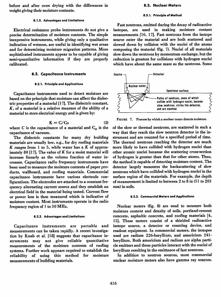
Fast neutrons, emitted during the decay of radioactiveisotopes, are used in making moisture contentmeasurements [16, 171. Fast neutrons from the isotopesource enter the material and are both scattered andslowed down by collision with the nuclei of the atomscomposing the material (fig. 7). Nuclei of all materialsslow down the neutrons by momentum exchange, but thereduction is greatest for collisions with hydrogen nucleiwhich have about the same mass as the neutrons. Some
Source -Detector
Specimen surface
Paths of neutrons, some of whichcollide with hydrogen nuclei, becomeslow neutrons, strike the detector,and are counted
K = C/Co (2)where C is the capacitance of a material and CO is thecapacitance of vacuum.
The dielectric constants for many dry buildingmaterials are usually low, e.g., for dry roofing materialsK ranges from 1 to 5, while water has a K of approx-imately 80 [17]. The value of K for a moist material willincrease linearly as the volume fraction of water in-creases. Capacitance radio frequency instruments havebeen used to measure the moisture contents of paper pro-ducts, wallboard, and roofing materials. Commercialcapacitance instruments have various electrode con-figurations. The electrodes are attached to a constant fre-quency alternating current source and they establish anelectrical field in the material being tested. Current flowor power loss is then measured which is indicative ofmoisture content. Most instruments operate in the radiofrequency region of 1 to 30 MHz.
8.2.2. Advantages and Limitations
Capacitance instruments are portable andmeasurements can be taken rapidly. A recent investiga-tion by Knab et al. [18] suggests that capacitance in-struments may not give reliable quantitativemeasurements of the moisture contents of roofingsystems. Further work appears required to establish thereliability of using this method for moisturemeasurements of building materials.
FIGURE 7. Process by which a nuclear meter detects moisture.
of the slow or thermal neutrons, are scattered in such away that they reach the slow neutron detector in the in-strument and are counted for a specified period of time.The thermal neutrons reaching the detector are muchmore likely to have collided with hydrogen nuclei thanother atomic nuclei because the scattering cross-sectionof hydrogen is greater than that for other atoms. Thus,the method is capable of detecting moisture content. Thedetector largely measures the backscattering of slowneutrons which have collided with hydrogen nuclei in thesurface region of the materials. For example, the depthof measurement is limited to between 2 to 8 in (51 to 203mm) in soils.
8.3.2. Commercial Meters and Applications
Nuclear meters (fig. 8) are used to measure bothmoisture content and density of soils, portland-cementconcrete, asphaltic concrete, and roofing materials [4,15]. These meters consist of a shielded radioactiveisotope source, a detector or counting device, andreadout equipment. In commercial meters, the isotopesused are radium 226-beryllium, and americium 241-beryllium. Both americium and radium are alpha parti-cle emitters and these particles interact with the nuclei ofberyllium resulting in the emittance of fast neutrons.
In addition to neutron sources, most commercialnuclear moisture meters also have gamma ray sources.
416
FIGURE 8. Nuclear meter used to measure moisture contents ofmaterials.
The gamma rays are used to determine the density ofmaterials. See section 13 for explanation of the principle.
8.3.3. Advantages and Limitations
Nuclear meters are portable and moisturemeasurements can rapidly be made on materials.However, the hydrogen atoms of building materials inaddition to those of water will contribute to the numberof detected thermal neutrons. For example, asphalt in aroofing membrane may contribute to a reading becauseit contains bonded hydrogen atoms. For hydrogen-containing materials, calibration of the meter is requiredusing samples identical to those expected during field in-spection. Also, a license must be obtained from theNuclear Regulatory Commission for domestic use of theradioactive isotopes in the neutron source of the neutronmoisture meters.
8.4. Infrared Thermography
In addition to detecting heat loss, infrared ther-rnography can be used to detect moisture in buildingmaterials if heat is flowing through them. The presenceAf moisture will effect the heat transfer properties ofmaterials which permits the identification of wet areasWy thermography. The principle involved in makinglhermography scans is discussed in section 16. Thismethod is being used in making aerial scans of roofs,Nhereby large roof areas and many buildings can besanned in a relatively short time 115]. Hand held in-rared cameras also are being used to measure heat lossesmd to detect moisture in roofing systems 1i91. See sec-
tion 16 for additional applications of this method.In using the thermography method to detect moisture
in roof systems, it is necessary to assume thattemperature gradients are caused by moisture and arenot associated with differences in roofing composition orthickness. Because construction and thickness variationscan be present, results from thermographic inspectionsshould be interpreted carefully.
9. Point Inspection Gage (Tooke Gage)
9.1. Principle and Applications
The paint inspection gage is used to measure dry paintfilm thickness by the microscopic observation of a smallV-groove cut into the paint film. In addition, the numberof paint layers and their individual thickness can bedetermined. The thickness of dry coating applied to anytype of surface (e.g., wood, metal, glass, or plastic) can bemeasured. A commercially available paint inspectiongage, the Tooke Gage, is shown on figure 9. This gage isportable having overall dimensions of 4.5 x 3.5 x 1 in(114 x 89 x 25 mm) and weighing 26 oz. (.74 kg). Threecutting tips are furnished permitting the measurement offilm thickness up to 50 mils (1.3 mm).
I
FIGURE 9. Tooke gage for measuring the thicknesses and/ornumber of paint layers.
417
9.2. Limitations
A disadvantage of this method is that a cut is made inthe paint film which may need to be repaired, dependingon the substrate and the severity of the environment.
10. Pin Hole Detector
10.1. Principle and Applications
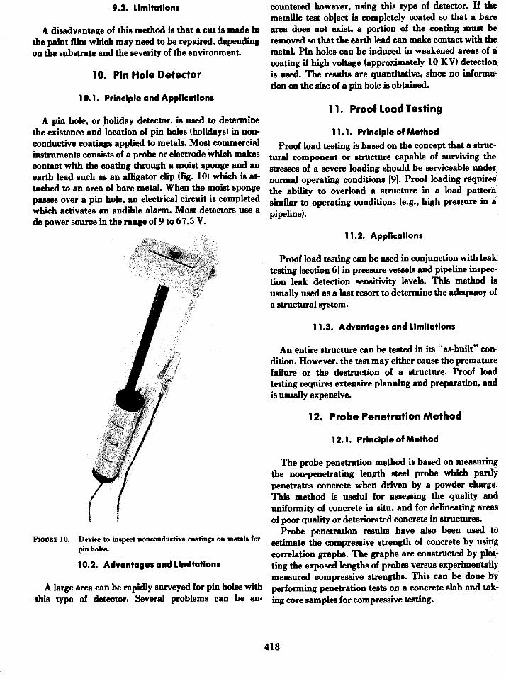
A pin hole, or holiday detector, is used to determinethe existence and location of pin holes fholidays) in non-conductive coatings applied to metals. Most commercialinstruments consists of a probe or electrode which makescontact with the coating through a moist sponge and anearth lead such as an alligator clip (fig. 10) which is at-tached to an area of bare metal. When the moist spongepasses over a pin hole, an electrical circuit is completedwhich activates an audible alarm. Most detectors use adc power source in the range of 9 to 67.5 V.
FIGURE 10. Device to inspect nonconductive coatings on metals forpin holes.
10.2. Advantages and Limitations
A large area can be rapidly surveyed for pin holes with-this type of detector. Several problems can be en-
countered however, using this type of detector. If themetallic test object is completely coated so that a barearea does not exist, a portion of the coating must beremoved so that the earth lead can make contact with themetal. Pin holes can be induced in weakened areas of acoating if high voltage (approximately 10 KV) detectionis used. The results are quantitative, since no informa-tion on the size of a pin hole is obtained.
11. Proof Load Testing
11.1. Principle of Method
Proof load testing is based on the concept that a struc-tural component or structure capable of surviving thestresses of a severe loading should be serviceable undernormal operating conditions 191. Proof loading requiresthe ability to overload a structure in a load patternsimilar to operating conditions (e.g., high pressure in apipeline).
11.2. Applications
Proof load testing can be used in conjunction with leaktesting (section 6) in pressure vessels and pipeline inspec-tion leak detection sensitivity levels. This method isusually used as a last resort to determine the adequacy ofa structural system.
11.3. Advantages and Limitations
An entire structure can be tested in its "as-built" con-dition. However, the test may either cause the prematurefailure or the destruction of a structure. Proof loadtesting requires extensive planning and preparation, andis usually expensive.
12. Probe Penetration Method
12.1. Principle of Method
The probe penetration method is based on measuringthe non-penetrating length steel probe which partlypenetrates concrete when driven by a powder charge.This method is useful for assessing the quality anduniformity of concrete in situ, and for delineating areasof poor quality or deteriorated concrete in structures.
Probe penetration results have also been used toestimate the compressive strength of concrete by usingcorrelation graphs. The graphs are constructed by plot-ting the exposed lengths of probes versus experimentallymeasured compressive strengths. This can be done byperforming penetration tests on a concrete slab and tak-ing core samples for compressive testing.
418
12.2. Probe Equipment and Use
The Windsor Probe is the most commonly selected,and possibly the only commercially available apparatusin the U.S. for measuring the penetration resistance ofconcrete. It consists of a special driving gun (fig. 11) intowhich a high-strength steel probe is inserted. This probeis driven into the concrete by firing a charge la 32 caliberblank with a precise quantity of powder). A series ofthree measurements is made in each area using thespacer plate shown in figure 12. The length of a probeextending from the surface of concrete can be measuredusing a simple device as shown in figure 13.
f t0000000000000a,"0N'ES-0.-0': j: :: -I f D:fiEd: ::kE.tiSXV 0 _
f : : : E W g E f: , a f Ha_
f -ffEs -
FIGURE 12. Windsor probe in use.
FIGURE 13. Device for measuring length of probe extending fromsurface of concrete.
Operating procedures for the Windsor Probe are givenby the manufacturer. In addition, testing procedures aregiven in ASTM Standard C803 [201. The probe can beeasily operated by concrete inspectors, and is readily por-table.
The manufacturer supplies a set of five calibrationcurves, each curve corresponding to a specific Mob'shardness for the coarse aggregate used in the concrete,by which probe measurements can be converted to com-pressive strength values. However, Arni [21] observedthat use of the manufacturer's calibration curve oftenresults in grossly incorrect estimates of the compressivestrength of concretes. Therefore, it is recommended thatthe Windsor Probe should be calibrated by the in-dividual user, and should be recalibrated whenever thetype of aggregate or the concrete propagation is changed.
12.3. Applications
The Windsor Probe can be used for assessing thequality and uniformity of concrete because physical dif-ferences in concrete will affect its resistance to penetra-tion. A probe will penetrate deeper as the density, sub-surface hardness, and strength of the concrete decreases.Areas of poor concrete can be delineated by making aseries of penetration tests at regularly spaced locations.
The Windsor Probe has been used to estimate thecompressive strength of concrete. However, the relation-ship between the depth of penetration of the probe andthe compressive strength can only be obtained empiri-cally because penetration of the probe depends on a com-plex mixture of tensile, shear, and compressive forces[211. The estimation of compressive strengths with theWindsor Probe, therefore, must be made using a correla-tion diagram with appropriate confidence limits.
419
The probe technique appears to be gaining acceptanceas a practical NDE method for estimating the com-pressive strengths of concrete. Improved correlationsbetween probe results and in-place strength can be ob-tained by keeping the curing conditions of the testspecimens close to those expected for the in-place con-crete and by making sure that the test concrete isrepresentative of the in-place concrete. If the WindsorProbe is calibrated using concrete specimens taken froman early construction stage, the calibration chart couldbe used to estimate the strength of concrete placed dur-ing later stages (assuming that the concrete design is thesame).
12.4. Advantages and Limitations
The Windsor Probe equipment is simple, durable, re-quires little maintenance, and can be used by inspectorsin the field with little training. Care must be exercised,however, because a projectile is fired and safety glassesshould be worn. The gun can only be fired when it ispushed against a special spacer plate.
The Windsor Probe primarily measures surface andsubsurface hardness and does not yield precisemeasurements of the in situ strength of concrete.However, useful estimates of the compressive strength ofconcrete may be obtained if the probe is properlycalibrated. The probe test is very useful in assessing thegeneral quality and relative strength of concrete in dif-ferent parts of a structure.
The Windsor Probe test does damage the concrete,leaving a hole of about 0.32 in (8 mm) in diameter for thedepth of the probe and, also, may cause minor crackingand some surface spalling, necessitating minor repairs.
13. Radiography
Radiography enables the inspection of the internalstructure of a test object through the use of penetratingradiation, which may be electromagnetic (X-ray, gammarays, etc.) or particulate (neutrons) [1, 22, 23]. The ob-ject is exposed to a radiation beam and the intensity ofthe radiation passing through the object is reduced ac-cording to variations in thickness, density and absorp-tion characteristics of the object. The quantity of radia-tion passing through the object is measured and used todeduce the internal structure of the test object. The typesof radiation that have been most widely used are X-raysand gamma rays, with gamma rays being most com-monly used during field inspections.
13.1. X-rays
X-rays are produced by bombarding a target materialwith fast moving, high energy electrons. The high energyelectrons collide with electrons in the target, which arepromoted to higher energy levels. X-rays are emitted aselectrons fill the vacancies left by the promoted elec-trons. The generation of X-rays takes place in anevacuated chamber (X-ray tube) in which high energyelectrons are generated by applying a very high voltagebetween an incandescent filament (the electron source)and the target material. By varying the voltage, X-rayswith different penetrating abilities can be generated. Forexample, 200 kV (kilovolt) X-rays are capable ofpenetrating about 1 in (25 mm) of steel, while 400 kV X-rays can penetrate up to 2 in (51 mm) of steel [1], whichis about the maximum attainable with portable equip-ment. In general, the penetrating ability of X-rays of agiven energy level decreases as the density of the objectincreases. Portable gamma radiography units areavailable with greater penetrating capabilities than por-table X-ray units. Therefore, gamma radiography ismore commonly used for field inspections.
13.2. Gamma Rays
Gamma rays are physically indistinguishable from X-rays, the primary difference is the source. Gamma raysare the results of radioactive decay of unstable isotopes,and as a result there are some basic differences betweengamma ray and X-ray radiography. Because gammarays are due to nuclear disintegrations, a gamma raysource will lose its intensity with time and longer ex-posure times may be required for adequate inspection.In addition, each source produces rays of fixedpenetrating ability. Isotopes of thulium, iridium, cesium,radium and colbalt have been used for radiography.Thulium has a penetrating ability of 1/2 in (13 mm) ofsteel, while cobalt produces gamma rays capable ofpenetrating up to 9 in (230 mm) of steel. The gammasources usually used for inspecting concrete are given intable 1.
Note that the relative penetration abilities of thegamma rays are controlled by their energies.
13.3. Principle and Applications
Gamma or X-ray radiation is attenuated (reduced)when passing through materials. The extent of attenua-tion is dependent on the density and thickness ofmaterial, and on the energy of the rays. In radiography,differences in radiation attenuation produced by varia-tions in the density and thickness of a material are
420
TABLE 1. GAMMA RAYSOURCES[221
Radioactive Gamma Optimum WorkingSource Energy Half-life Thickness of Dose
(MeV) (t 1 /2 Concrete (mm) Ratea
Iridium 192 0.296 70 days 30-200 0.55and
0.613
Cesium 137 0.66 33 years 100-300 0.39
Colbalt 60 1.17 5.3 years 150-450 1.35and1.33
'Roentgens per hour per curie at 1 m.disintegrations per second.
One curie is equal to 3.7 x 10¹⁰
recorded on photographic film. For example, when rein-forced concrete is radiographically inspected, steel rein-forcement attenuates the radiation more than concreteand appears as a lighter area in the film. Voids andcracks in the concrete will appear as darker areas on thefilm due to less attenuation of the incident radiation.
In practice, penetrating rays generated by a suitablesource are allowed to pass through materials, withemerging radiation being recorded on X-ray film held ina light-tight cassette. Some of the applications of gammaradiography are inspection of concrete to locate reinforc-ing bars, and to determine if excess porosity or voids arepresent [24]; inspecting welds for cracks, voids, and slaginclusion; and inspecting masonry walls for the presenceof reinforcement or grout.
sources are inherently hazardous because they emit rayscontinuously and high energy sources have extremelyhigh penetrating ability. As a result, gamma ray sourcesrequire large amounts of shielding material which limitsthe portability of gamma radiography equipment. Theuse of gamma ray producing isotopes is closely con-trolled by the Nuclear Regulatory Commission, and alicense is required to use them.
14. Seismic Testing
14.1. Principle of Method
Seismic testing is the evaluation of material integrityby analysis of shock wave transmission rates and effects19]. An array of sensing devices around an explosivecharge of known energy (the most common shock loadinput system) is used to record shock wave transmissionrates. These shock wave transmission rates can berelated to material densities. Vibrational patterns in-duced from shock loading can be used to determine reso-nant frequencies in structures.
14.2. Applications
Seismic testing can measure soil densities and locatedensity variation boundaries (figure 14). Soil density
I Er
A
* -SENS
mII
OIRSEXPLOSIVECHARGE
1iv
.0
13.4. Advantages and Limitations
Radiography provides a method for readilycharacterizing the internal features of an in-placematerial or building component. This method is ap-plicable to a variety of materials. Portable gammaradiography units can have greater penetrating abilitiesthan portable X-ray units.
The most important drawback of radiography is thehealth hazard associated with the penetrating radiation.A radiographic inspection program should be plannedand executed by individuals who have been trained andare qualified to perform this type of inspection. All per-sonnel involved in radiographic inspection must carrydevices that monitor the radiation dosage to which theyhave been exposed and must be protected so that thedosage rate does not surpass Federal limits. Gamma ray
t-
B-j4=
I I I I I I
I EI mH ]I ITEST ZONE
iv
FIGURE 14. Schematic of seismic testing [91(A) Shock wave pattern (B) Seismic test data plot
421
values can then be related to load bearing capacities andfoundation preparation requirements. Seismic testingcan also be used to check structures for possible resonantfrequencies that could cause failure under operatingdynamic loads.
14.3. Limitations
Seismic testing is applicable only to monitoring soilconditions and structural vibrations. Multi-channelrecording systems, power cables, and a large number ofsensing devices are required for seismic testing. Thehazards of explosives are also involved in the testing, butall components of a seismic test system are portable.
15. Surface Hardness Testing
Surface hardness methods are generally used to obtainan indication of the strength level or quality of amaterial rather than for flaw detection. Hardness inthese tests refers to the resistance a material offers to in-dentation by an object. Indentation is produced understatic or impact loading conditions; and the most com-mon applications are in testing metals and concrete.
15.1. Static Indentation Tests
These methods are primarily used in testing metals.They commonly involve indenting the surface with an in-dentor of fixed geometry under specified loads [1]. Theindenter has a small point and thereby produces highstresses in the metal at the point of contact. The stressesare sufficient to cause the metal to yield beneath the in-denter and a permanent indentation results. Themagnitude of the indentation will depend on the strengthof the metal, the applied load, and geometry of the in-denter. Therefore, by measuring the size of the indenta-tion under a given set of conditions, an estimate ofstrength can be obtained.
15.1. 1. Standard Methods
There are three widely used standard methods forhardness testing metals. The Brinell method [1] involvesapplying a constant load (500, 1500 or 3000 kg) on a 0.4in (10 mm) diameter hardened steel ball-type indenterand measuring the diameter of the indentation on thetest piece with a microscope. A hardness number isdetermined by substituting the values of the appliedload, ball diameter, and indentation diameter into astandard formula. An example of a Brinell test resultwould be 400 HB, in which 400 is the numbercalculated from the standard formula, "H" stands for
hardness and "B" for Brinell. For weaker metals asmaller load would be used to produce the indentation.
The Vickers method [11 is similar to the Brinellmethod except that a square-based pyramidal diamondindenter is used and the applied loads are much smaller.The diagonal of the square indentation is measured, andits value and the applied load are substituted into a stan-dard equation to calculate the Vickers hardness number(HV).
The most common method is the Rockw, ell hardnesstest [1]. In this method the depth of additional perma-nent indentation that occurs as the load is increased froma small load to the test load is measured. The test instru-ment measures the depth automatically and the hardnessnumber is read directly from a scale on the instrument.The Rockwell test can be performed much faster thanthe previously described methods. There are five dif-ferent indenters and three different test loads that can beused; therefore, there are 15 different Rockwell hardnessscales. For example, the result 60 HRC indicates a hard-ness number of 60 on the Rockwell C scale. The varietyof scales permits testing a wide range of metals from verysoft (weak) to very hard (strong).
15.1.2. Usefullness of Static Tests
Tables are available that permit conversion of thehardness number from one test method to the equivalentnumber of another test method (for example, ASTME140)[25]. Tables are also available giving approximatetensile strengths of meta ls corresponding to the differenthardness numbers. Care must be exercised in using thestrength tables, because each is applicable to only certaintypes of metals.
Portable hardness testers are available for in-placetesting of metal structures.
15.2. Rebound Hammer Method
The rebound method is based on the rebound theoriesof Shore [26]. He developed the Shore Scleroscopemethod in which the height of rebound of a steel hammerdropped on a metal test specimen is measured. The onlycommercially available instrument based on the reboundprinciple for testing concrete is the Schmidt ReboundHammer [271.
The Schmidt Rebound Hammer has gained wide ac-ceptance by researchers and concrete inspectors and isone of the most universally used nondestructive testmethods for determining the in situ quality of concreteand for deciding when forms may be removed. Stan-dards [28] have been drafted in Poland and Romania forthe Rebound Hammer. The British Standards Institu-
422
tion has issued Building Standard 4408 which coversnondestructive test methods for concrete, and includesthe rebound hammer method in part 4 of the Standard[281. Recently, ASTM issued Standard C805, Test forRebound Number of Hardened Concrete, which givesprocedures for the use of the rebound hammer.
15.2.1. Description of Method
The Schmidt Rebound Hammer consists of a steelweight and a tension spring in a tubular frame (figure15). When the plunger of the hammer is pushed againstthe surface of the concrete, the steel weight is retractedagainst the force of the spring. When the weight is com-pletely retracted, the spring is automatically released,the weight is driven against the plunger and it rebounds.
FIGURE 15. Schmidt rebound hammer.
The rebound distance is indicated by a pointer on a scalethat is usually graduated from zero to 100, and the re-bound readings are termed R-values. The determinationof the R-values is outlined in the manual supplied by themanufacturer. R-values give an indication of the hard-ness of the concrete with values increasing with the hard-ness of the concrete.
Each hammer is furnished with a calibration chart,showing the relationship between compressive strengthof the concrete and rebound readings based on data fromtests conducted by the Swiss Federal Materials Testingand Experimental Institute. Users should not place toomuch confidence on the calibration chart, however, asthey should develop their own for each concrete mix andfor each rebound hammer.
15.2.2. Applications
Numerous investigators 129-311 have shown that thereis some correlation between compressive strength of con-crete and the hammer rebound number. Extensivedisagreement exists, however, (e.g., Refs 1321 and 1331)concerning the accuracy of the strength estimates fromrebound measurements. Mitchel and Hoagland 1341found that the coefficient of variation for estimated com-pressive strength, for a wide variety of specimens fromthe same concrete, averaged 18.8 percent. Arni 1211found that the rebound hammer gave a less reliable
estimate of compressive strength than the WindsorProbe.
Several investigators (33, 351 have attempted toestablish correlations beteen the flexural strength of con-crete and the hammer rebound number. Relationshipssimilar to those obtained for compressive strengths wereobtained, except that the statistical variations were evengreater.
Mitchel and Hoagland 1341 attempted to correlate re-bound numbers with the modulus of elasticity of the con-crete specimens. They concluded that no valid correla-tions could be made. Peterson and Stoll 1291 and Klieger1361 have developed some empirical relations betweenthe dynamic modulus of elasticity and hammer rebound.
The rebound hammer, like the Windsor Probe, is veryuseful in assessing the general quality of concrete and forlocating areas in which poor quality concrete is located.A large number of measurements can be rapidly taken sothat large exposed areas of concrete can be mappedwithin a few hours.
15.2.3. Advantages and Limitations
The rebound hammer provides a simple and quickmethod for the nondestructive testing of concrete in situ.The equipment is inexpensive, costing less than SI 000,and can be operated by field personnel with a limitedamount of instruction.
The rebound hammer, however, has recognizedlimitations. The rebound measurements on in situ con-crete are affected by [4, 33, 371:
(1) Smoothness of the concrete surface(2) Moisture content of concrete(3) Type of coarse aggregate(4) Size, shape and rigidity of specimen, e.g., a thinwall or beam(5) Carbonation of the concrete surface.
The rebound method is largely an imprecise test and itdoes not provide a reliable prediction of the strength ofconcrete. The rebound hammer, however, is very usefulin the rapid assessment of the relative quality of concreteand for estimating the relative strength of concrete.
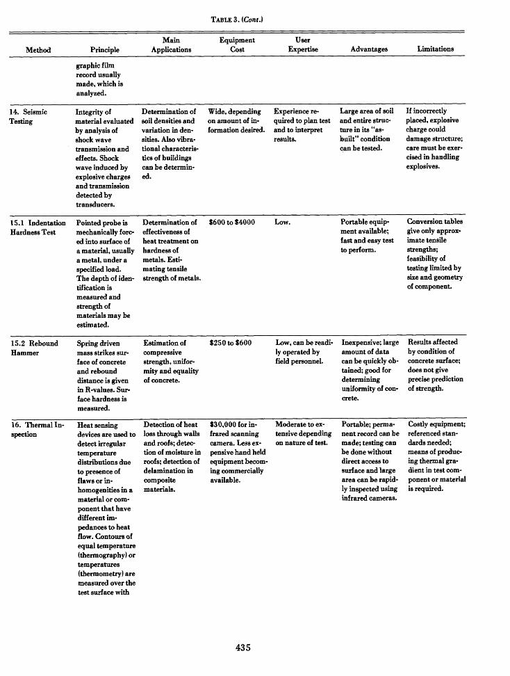
16. Thermal Inspection Methods
The presence of discontinuities in an object, such ascracks, voids or inclusions, will change the heat transfercharacteristics of the object. Thus, if is a transient heatflow condition exists, there will be nonuniform surfacetemperatures, and the pattern of the surfacetemperatures can be used as an indirect indicator of sub-
423
surface anomalies [1]. Thermal inspection can also beused to detect anomalous operating characteristics of asystem, such as over loaded electrical wiring or heat lossthrough walls and roofs of buildings. The followingdiscussion will address primarily the application of ther-mal inspection to detect anomolies in the internal struc-ture of test objects such as structural metallic com-ponents and roofing systems.
16.1. Principles of Thermal Inspection
To establish the conditions for thermal inspection, aheat flow situation must exist or be created. If necessary,this can be done by applying a temporary heat source tothe front or back surface of the test object. The flow ofheat from the warm to the cold surface will be affectedby the thermal diffusivity of the material which is itself afunction of its thermal conductivity, density, and specificheat. If discontinuities are present which have thermaldiffusivities that differ from the bulk material, local"hot" or "cold" spots will exist on the surfaces directlyover the location of the voids. Therefore, by measuringthe pattern of surface temperatures under heat flow con-ditions, subsurface flaws can be detected.
Detection of surface temperatures can be accom-plished by two methods: (1) contact inspection methods,and (2) non-contact inspection methods. With contactmethods, the surface is covered with a temperature sen-sitive material and differences in surface temperature arerecorded as a pattern of the coating material. Examplesof coatings that have been developed for this applicationare [11: heat sensitive paints and papers; phosphorcoatings whose fluorescence under ultraviolet light is af-fected by temperature; melting point coatings whichmelt when a specific temperature is reached; and liquidcrystals which undergo color changes as theirtemperatures are varied. Contact methods are generallynot very sensitive, have relatively long response times,and require an application procedure prior to thermal in-spection. Non-contact methods permit remote sensing ofthe thermal patterns, and are the most popular thermalinspection methods.
16.2. Infrared Thermography
16.2.1. Principle of Method
An object having a temperature above absolute zerowill emit energy in the form of thermal photons. Thewavelengths of the radiation fall within certain bandsdepending on the temperature. For example, at room
temperature, the wavelengths are typically from 4 to 40,um with a peak wavelength of about 10 Mm [1]. At veryhigh temperatures, the wavelengths of the emitted radia-tion are reduced to less than 1 micrometer and fallwithin the visible spectrum. The longer wavelengthradiation associated with room temperature is not visibleto the eye and is called infrared radiation. By using in-struments that can detect infrared radiation, it is possi-ble to "see" differences in surface temperatures. This isthe basis of the thermal inspection method known as in-frared thermography.
The rate of radiant energy emission per unit area ofsurface (W) is given by the Stefan Boltzmann Law:
W=edT4
where T is the absolute temperature,e is the emissivity, and6 is the Stefan Boltzmann constant(5.67 x 10⁻¹² watt/cm 2 /0K 4 ).
Thus, changes in temperature of a surface produce morethan proportional changes in emitted energy, and thisenables the detection of temperature differences as lowas 0.2 0 C with the available detection equipment.Emissivity refers to the efficiency of energy radiation bythe surface. The maximum radiation efficiency occurs ina "black body" and this is given an emissivity value of 1.All real surfaces have an emissivity while rough texturednon-metals have high emissivity. Since detectionmethods are based on the intensity of emitted radiation,a change in emissivity at various points on the surfacemay be incorrectly interpreted as a change intemperature. Surfaces with non-uniform or low emissivi-ty can be painted with high emissivity coatings.
16.2.2. Remote Inspection
Infrared thermography permits remote inspection ofthe test object. This is made possible because air is prac-tically transparent to the infrared wavelengths asso-ciated with near room-temperature conditions [17].However, high water content will reduce the transmis-sion of infrared radiation through air so that problemsmay arise under humid conditions. The most commonmethod for detecting infrared radiation is with semicon-ductor crystals whose electrical properties are altered byincident infrared radiation. For best sensitivity, thecrystals should be kept cold with liquid nitrogen and thisplaces some limitations on the portability of the detec-tion systems. Dewar flasks are required to hold the li-quid nitrogen, and the nitrogen needs to be replaced as itevaporates.
424
16.4. Advantages and Limitations
Infrared scanners consist of a sensing or camera-likeunit and a display or recording unit. The elements of acamera unit are shown schematically in figure 16 andthese components scan the viewed area and focus the in-dividual "points" on a sensor or radiation detector. Asshown in figure 16, the radiant flux which is related tothe temperature of the selected viewing area passesthrough an infrared transparent lens and a mechanical-optical scanner. The mechanical-optical scanner, whichconsists of rotating or vibrating mirrors or prisms, pro-vides a vertical and horizontal scan of the virtual imagefrom the lens.
IR
lenses
Mechanical-apticalscanner
Infrared transparentcamera fens
Field seen by camera
FIGURE 16. Schematic of infrared camera.
The picture is presented as shades of gray correspond-ing to variations in surface temperatures of the viewedobject. A calibration strip is also shown so that theshades can be converted to absolute temperatures ifdesired. It is also possible to have a color display inwhich different temperatures are shown with differentcolors.
16.3. Applications
Thermal inspection methods have been applied fordetecting disbonds in laminated materials, entrappedmoisture, material density gradients, and anomalies incastings [1l. In the construction area, infrared ther-mography has been applied to compare thermalresistances of roofs, to detect water penetration intobuilt-up roofs, to detect heat loss through walls and roofsqf buildings, and to detect overloaded electrical circuits[1 7]. Recently, infrared thermography has been used todetect deteriorated regions in bridge decks [381.
Thermal inspection equipment is generally portableand a permanent record (photograph) can be made of theinspection results. By using thermal infrared ther-mography, inspections can be performed without directaccess to the surface and large areas can be rapidly in-spected.
In determining the size and location of detectableflaws, it should be recognized that under heat flow condi-tions the surface temperature patterns will be a functionof the type and size of the discontinuity, the heat intensi-ty applied or flowing to the surface of the object, and theobservation time [1]. The sensitivity of infrared thenmography in detecting internal flaws is a complex func-tion of these variables. The results of such inspections,therefore, should be carefully interpreted.
17. Ultrasonic Pulse Methods
In the ultrasonic pulse methods sound waves whichare beyond the audible range are induced in a test objectgenerally by means of a peizoelectric transducer, andeither reflected waves or those passing through the objectare detected by a similar type of transducer [1, 4, 39-42].When reflected waves are detected, the technique isreferred to as "pulse-echo" and the transmittingtransducer may also act as the receiver. Waves passingthrough the object (velocity methodi are detected with asecond transducer, i.e., a receiving transducer.
The application of ultrasonic inspection is based ontwo principles: U1) the velocity of the acoustic waves in amaterial is a function of its elastic constants and density;and (2) when an acoustic wave encounters an interfacebetween dissimilar materials, a portion of the wave isreflected. The amount of reflection depends on themismatch in acoustic impedance (product of wave veloci-ty and density) of the materials with the amount ofreflection increasing with the mismatch.
17.1. Ultrasonic Pulse Velocity Method
The ultrasonic pulse velocity method is one of themost universally used NDE methods for assessing thequality of concrete. It has been used in both thelaboratory and in the field for the 7past 40 years. Somefield applications have included checking the quality ofconcrete in bridge piers, pavements and dams.
17.1.1. Principle of Method
The ultrasonic pulse velocity method is based onmeasuring the travel time of an ultrasonic pulse passing
425
16.2.3. Infrared Scanners and Display
through a material. The pulse generated by an electro-acoustic transducer is picked up by a receiver transducerand amplified.
The time of travel of the pulse is measured elec-tronically 1421. A commercial instrument for measuringthe ultrasonic pulse velocity of concrete is shown infigure 17.
FIGURE 17. Ultraonic pulse velocity equipment.
When a mechanical pulse is applied to a material byan electroacoustical transducer, waves are induced in thematerial. Usually longitudinal waves are used in testingconcrete. These waves are transmitted by particlesvibrating parallel to the direction of propagation. Thevelocity of the waves is controlled by the elastic proper-ties and density of the material, and is virtually indepen-dent of the geometry of the object being tested.
If a longitudinal wave encounters a discontinuity suchas a crack or void, it may "bend," i.e., be diffractedaround the discontinuity. This increases the internaldistance the wave must pass between the transmittingand pickup transducers, and consequently its travel timeincreases. Therefore, for a given separation of thetransducers, and for a given concrete, the travel time of alongitudinal wave will be affected by changes in densityand elastic properties along the travel path.
Several ultrasonic pulse velocity units are commer-cially available for testing concrete and cost about$4000. They can be used to test concrete having athickness up to about 75 ft (30 m) depending on thespecific model.
17.1.2. Application for Assessment of Condition of Concrete byUltrasonic Pulse Velocity
The ultrasonic pulse velocity method is considered tobe the best NDE method for determining the uniformityof in situ concrete, and ASTM Standard C 597 gives thestandard test procedure to use. For example, velocitymeasurements have been successfully used to detectdeteriorated regions in concrete bridges and the unifor-mity of concrete in walls [41. In general, if substantialvariations in pulse velocities are found in a structure,
without any apparent reason (such as intentionalchanges in materials, concrete mix, or construction pro-cedures), this indicates that unsound concrete is present.
A general rating which has been proposed [431 toassess the relative quality of concrete is presented intable . Three criteria should be used with caution asdifferences in the qualities of concrete cannot be asharply delineated as indicated in table 12. In addition,velocity is affected by the density and amount of ag-gregate in the concrete. A crude assessment of the qual-ity of similar types of concrete can be made, however, us-ing these criteria. For example, if one concrete has apulse velocity of 15,000 ft/s (4570 m/s) while anotherconcrete with a similar composition has a velocity below10,000 ft/s (3050 m/s), then there is clearly a significantdifference in their qualities.
17.1.3. Estimation of Strength Properties of Concret
Numerous investigations have attempted to correlatecompressive and flexural strengths of concrete with pukevelocity. Some correlations have been obtained inlaboratory studies, provided that mix proportions, ekcement, types of aggregate, and curing conditions weenot varied. If these factors were varied, however, sousable correlations were obtained. For example, Parker1441 made a comparison of pulse velocities and cm-pressive strengths for concretes made from only one typeof aggregate but containing different cements from dif-ferent sources and a variety of admixtures. His analyshof the total data indicated that at the 95 percent ecmfidence level the estimate strength of 4440 psi (30.7MN/m 2 ) concrete ranged from about 2100 to 6000 put(14.5 to 41.8 MN/m2 ). Obviously, the ultrasonic pulemethod cannot be used to obtain reliable estimates of thcompressive strength of concrete in structure when iEecomposition is unknown.
Probably the best concluding remarks regardingstrength prediction from wave propagation methods wethose stated by Jones [451:
426
"In spite of the promising results of the early investiga-tions, it must be concluded that no general relation hasbeen found between the dynamic modulus of elasticityand its flexural or compressive strength. "
This statement still holds if one substitutes "pulse veloc-ity" for "dynamic modulus of elasticity."
17.1.4. Extraneous Effects on Velocity Measuremonts
The measurement of the pulse velocity of concrete isaffected by several factors which are not intrinsic proper-ties of concrete, and, therefore, are not a function of thequality or strength of concrete [41:
(1) Smoothness of concrete at transducer contactarea. Good acoustical contact between thetransducers and concrete is required. In addition,a coupling agent such as an oil or a jelly must beused.
(2) Concrete temperatures outside of the range be-tween 410 and 86 OF (50 and 30 0C) affect themeasured pulse velocity. Below this temperaturerange, the velocity is increased, and above thevelocity is decreased.
(3) Moisture condition of concrete. Pulse velocitygenerally increases as the moisture content of con-crete increases, while compressive strengthdecreases as moisture content increases.
(4) Presence of reinforcing steel. The pulse velocityin steel is 1.2 to 1.9 times the velocity in concrete.Measurements made near steel reinforcing bars,therefore, may not be representative of the con-crete. If possible, measurements should be madeperpendicular to the longitudinal axis of the bars.If measurements must be made parallel to thelongitudinal axis of the steel bars, crude correc-tion factors are available.
17.2. Ultrasonic Pulse Echo Method
17.2.1. Principle of Method
In the ultrasonic pulse echo method waves which arereflected off of discontinuities (e.g. cracks and voids) andfrom interfaces (e.g. interfaces between concrete andsteel or between concrete and air) are recorded. Both thetransmitting and receiving transducers are contained inthe same probe, thus, only those waves which arereflected back at nearly 1800 to the incident waves are
detected. The penetrating ability of the ultrasonic pulseand the minimum size of detectable flaws are influencedby the frequency of the generated waves. High frequencyresults in less penetration but better sensitivity than lowfrequency.
17.2.2. Applications
Echo techniques have been extensively used to iden-tify and locate discontinuities and defects in metals andwelds [1, 39-411. The echo technique is one of the mostversatile and accepted NDE methods for metals.However, its application to concrete has been slow,largely because the extensive pore system, presence ofcracking, and the heterogeneous nature of concreteresult in multiple reflections when high frequency pulsesare used which both significantly attenuate the reflectedwaves and complicate the interpretation of the observa-tions. It may, however, be possible to combine the echomethod with acoustic impact (see section 2) so that lowfrequency waves are generated which would be insen-sitive to microscopic flaws but could be used to detectlarge discontinuities. Commercial equipment is not atpresent available for this type of testing.
17.2.3. Advantages and Limitations
Ultrasonic pulse-echo inspection offers several ad-vantages over other NDE methods capable of detectinginternal flaws in a test object such as gammaradiography [1J. For example, acoustic waves have ex-cellent penetrating ability, and with proper instrumentselection thick sections on the order of 10 m or more canbe inspected. Very small flaws may be detected and theirlocation and geometry may be estimated with reasonableaccuracy. In addition, test results are immediatelyavailable, the equipment is lightweight and portable,and acoustic waves pose no known health hazard.
Because of the indirect nature of flaw detection byultrasonic pulse-echo inspection, a high level of expertiseis required to plan an inspection program. A thoroughunderstanding of the nature of the interactions betweenthe acoustic waves and different discontinuities is re-quired in order to properly interpret test results. Thephysical testing, on the other hand, may be performed bytechnical level personnel after proper training. Beforeultrasonic inspection equipment can be used, calibrationand referencing with standards must be performed,otherwise test results are difficult to interpret. Thenature of the calibrations will depend on the particularinspection program.
427
18. Visual Inspection
Often surface defects can be detected visually usingmethods to enhance ordinary visual acuity. Opticalmagnification or other techniques which can be used toincrease the apparent size of surface cracks are coveredin this section.
18.1. Optical Magnification
Available magnifying instruments range from simpleinexpensive glasses to expensive microscopes. Some fun-damental principles about the operating characteristicsof magnification instruments need to be understoodbefore selecting a system for a particular application.First, the focal length decreases as the magnificationpower increases. This means that when high magnifica-tion is desired, the primary lens must be placed close tothe test object. The field of view (that portion of the ob-ject that can be seen at any instant) also decreases asmagnification power increases. A small field of viewmeans that it will be tedious to examine a large surfacearea. Another important parameter is the depth of field,which refers to the elevation difference of rough texturedsurfaces that can be viewed in focus simultaneously; thedepth of field decreases as the magnification power ofthe instrument increases. Therefore, to inspect a rough-textured surface, a magnification power should beselected that gives a sufficiently large depth of field sothat the "hills" and "valleys" will be simultaneously infocus. Finally, the illumination intensity required toclearly see surface flaws will increase as the magnifica-tion power increases. High magnification may requireusing a supplementary light source to augment theavailable lighting.
A useful tool for field inspection is a pocket magnifierwith a built-in measuring scale which enables measure-ment of flaw dimensions. A stereomicroscope is veryuseful when a three-dimensional view of the surface is re-quired. With this instrument one can determine whethera crack is shallow or extends for considerable distanceinto the object. By calibrating the focus adjustment, astereomicroscope can also be used as a depth gage tomeasure the approximate height of surface irregularities.
18.2. Fiberscope
Another useful instrument is the fiberscope, which iscomposed of a bundle of flexible optical fibes and lenssystems. The fiberscope can be used to look inside a cav-ity by inserting it through a small access hole. Some ofthe fibers in the bundle are used to carry light into thecavity and illuminate the field of view. The viewing head
can be rotated so that a wide viewing angle is possiblefrom a single access hole. A fiberscope, because of thediscrete nature of light transmission by the fibers maynot have as good a resolution ability as a boroscope,which is a straight rigid tube using a lens system forviewing. The best resolution is obtained by an instru-ment with small diameter fibers in which the fiber densi-ty per unit area is high. To use a fiberscope requires drill-ing access holes if natural channels are not present, andthe holes must intercept cavities. The acoustic impacttechnique (section 4.2) can be used to locate hollow spotsfor subsequent fiberscope inspection.
18.3. Liquid Penetrant Inspection
In this method a highly visible dye is used to coat thesurface to be inspected [1, 461. Any cracks that are opento the surface will soak up the dye because of surface ten-sion and capillary effects. After application of the dyethe surface is cleaned. The dye which penetrated intocracks remains and can be visually observed, therebydisclosing the presence of cracks. The method is one ofthe most inexpensive inspection methods available. Itonly enables detection, however, of open flaws that in-tersect the surface of the object.
18.3.1. Description of Method
Dye penetration inspection involves the followingsteps: (1) cleaning the surface; (2) applying the dye; (3)removing excess dye from surface; (4) applying adeveloper; and (5) interpreting the results.
The objective of the cleaning procedure is to removeforeign matter from within cracks so that dye canpenetrate into them. The specific procedures to be usedwill depend on the condition of the surface. Care must betaken to ensure that the cleaning process does not smearthe cracks or fill the cracks with residues. For example,sandblasting a soft metal may "hammer" the surface tosuch an extent that cracks become closed and undetec-table.
The dye may be applied to the surface by spraying,painting or dipping. Two types of dye are available: oneis for viewing under ordinary light and is usually abrilliant red color; the other is fluorescent and viewedunder ultraviolet light. Fluorescent dyes offer the bestsensitivity for detecting small cracks. The dye is allowedto remain on the surface from 10 to 30 min (dwell time)before cleaning the surface.
Cleaning can be done by flushing the surface withwater or by wiping with a rag dampened with solvent.For water cleaning, the dye requires an emulsifyingagent so that it can be completely removed with water.
428
The agent is either already included within the dye or itis added to the coated surface prior to washing. Thisphase is very important; all excess dye needs to beremoved otherwise there will be false indications ofcracks. If the surface is very porous, inspection by thismethod may be difficult; if dye is not removed from thepores, there will be a loss of contrast as the surface willtake on a color that is a light shade of the dye. If dye isremoved from all pores, it will probably also be removedfrom some of the cracks.
After cleaning, the surface is allowed to dry and adeveloper is added. Developer is a fine powder added fortwo reasons: (1) it provides a uniform coloredbackground which increases contrast; and (2) it has ablotting effect, thereby drawing up the dye from withinthe cracks. The blotting action increases the apparentwidth of the cracks so that they become more visible.Developer can be applied as a dry powder or as a paint.The thickness of the developer layer is important, if it istoo thin there may not be good contrast; and if it is toothick, it may mask the cracks.
Finally, the prepared surface is inspected. If the ap-plication procedure was correctly performed, thepresence of cracks will be clearly shown. However, theinspector needs to be familiar with the patternsassociated with "irrelevant indications," i.e., patternsnot due to cracks but due to other sources such as im-proper cleaning.
18.3.2. Advantages and Limitations
Although dye penetrant inspection relies on simpleprinciples, a certain amount of skill is necessary to prop-erly carry out the process. The operator needs to knowwhich materials to use for a particular application and tounderstand how the materials respond to differenttemperature conditions. Portable kits are available inwhich the various chemicals are contained in aerosolvans, thus making field inspection possible. At present,the technology has been developed primarily for inspec-tion of metals, and the applicability of the procedures tomasonry or concrete structures with surfaces of highporosity has not been demonstrated.
COMBINATIONS OF NONDESTRUCTIVEEVALUATION METHODS
While no single NDE method may be entirely satisfac-tory for predicting the strength or quality of a material,combinations of methods which respond to different fac-tors may give more definite information. The combinedNDE approach has been largely developed for
evaluating concrete and, therefore, only applications toconcrete will be described.
To predict the compressive strength of in situ concretemore accurately, the results of two or even three differentNDE methods have been combined. The most popularcombination has been the ultrasonic pulse velocitymethod in conjunction with the rebound hammer [47].Other common combinations are the ultrasonic pulsevelocity method and the measurement of the dampingconstant of concrete [481, and the ultrasonic pulse veloc-ity and pulse attenuation methods [49]. The latter twocombinations are essentially laboratory research techni-ques and therefore will not be discussed further.
The results of two methods can be combined in alinear equation of the form:
= A(NDE 1) + B(NDE 2) + C
where fc is the estimated compressive strength from thecombined method, NDE1 and NDE2 are the results ofthe individual methods, and A, B, and C are empiricallydetermined constants.
Combination of Ultrasonic Pulse Velocityand Rebound Hammer Methods
This combination of nondestructive tests has beenused in Europe, primarily, with the most exhaustivestudies being carried out by Facaoaru [50-53]. In thiscombined approach, measurements of ultrasonic pulsevelocity and rebound number are made in situ on con-crete. The pulse velocity and rebound number aresubstituted into a previously derived regression equationto predict compressive strength. It is believed that themultiple regression equation should give a more accurateestimate of compressive strength than either of the in-dividual measurements alone.
Facaoaru [501 has developed calibration charts forstandard concrete mixes from which the compressivestrengths can be estimated when the pulse velocities andrebound numbers are known. Correction factors havealso been developed to be used in the case of nonstan-dard concrete mixes. This combined method has beenused often in Romania to estimate the compressivestrength of in situ concrete 150, 521. Based on his ex-periences, Facaorau contends that by using the com-bined method, the following accuracy in predictions ofcompressive strengths can be obtained:
(1) When composition is known and test specimensor cores are available for calibration purposes, ac-curacy is within 10 to 15 percent.
429
(2) When only the composition of the concrete isknown, accuracy is within 15 to 20 percent.
3) When neither the composition is known nor testspecimens or cores are available, accuracy iswithin 20 to 30 percent.
This suggests that, for case (3), the combined methodgives no better prediction of the compressive strengththan can be obtained by measuring only the ultrasonicpulse velocity or only the rebound number; in case (2),the improvement is marginal. Therefore, only when theconcrete is well characterized is this combined methodbetter than the individual nondestructive methods.
SUMMARY
Nondestructive evaluation methods (NDE) offersignificant advantages over traditional methods fordetermining the properties of building materials. One ofthese is the ability to make in-situ measurements of thematerials, which virtually eliminates the specimenpreparation costs used with ordinary strength testingmethods. In-situ measurements are especially valuablein concrete technology because the characteristics ofhardened concrete are affected by such factors as ther-mal history, presence of moisture and degree of compac-tion. Testing concrete in the structure ensures that thesefactors have been included. Another advantage of NDEmethods is that they enable re-testing of the material orcomponent at later ages so that material degradationwith time can be determined. Finally, a majority of theNDE methods are economical and simple tests, permit-ting a larger number of tests for the same effort, com-pared with traditional test methods.
A key feature in the successful application of NDEmethods is an understanding of their operating prin-ciples and their inherent limitations. These aspects havebeen emphasized in the paper are summarized in table 3.The numbers shown for each method refer to the section
numbers in the text. The principle of operation will oftendictate the types of materials and the nature of thecharacteristics that can be probed with each method.
In selecting which particular NDE method one shoulduse, consideration should be given to the following fac-tors: (l) the type of material, since many methods are ap-plicable to only a particular type, such as concrete orsteel; (2) the properties being sought; (3) the level of ex-pertise required not only to perform but also to interpretthe tests; and (41 the desired level of accuracy.
The required calibration procedure should also beconsidered as this may increase the total effort to per-form an acceptable nondestructive inspection program.
The reliability of each method for a particular applica-tion depends on the relationship between the quantitymeasured directly by the method and the desired prop-erty. Methods are less reliable if their measurements arestrongly affected by factors which have negligible effecton the desired properties. Reliability can often be im-proved by careful calibration of the method; this isespecially critical to some of the NDE methods for con-crete strength prediction.
The future offers many opportunities for the growth ofNDE methods in building technology. The demand forsuch techniques is increasing, as is the level of researchto refine existing methods and develop new ones. It is an-ticipated that the exploitation of microcomputers willlead to a new generation of methods capable of measur-ing characteristics that are presently beyond our reach.
Preparation of this report was sponsored by the U.S.Army Construction Engineering Laboratory, Cham-paign, IL 61820. The authors appreciate the valuablesuggestions and information provided by Dr. PaulHowdyshell of the Engineering Laboratory and by Mr.Harry Berger, Office of Nondestructive Evaluation,National Bureau of Standards.
430
TABLE 3. Survey of Commonly used NDE Methods for Inspection Building Materials
Main Equipment UserMethod Principle Applications Cost Expertise Advantages Limitations
1. Acoustic Emis- During crack Continuous $10,000 for single Extensive Monitors struc- Requires means ofsion growth or plastic monitoring of pickup, up to knowledge re- tural response to loading structure;
deformation, the structure during S100,000 for quired to plan test applied load; complex electronicrapid release of service life to multichannel and to interpret capable of de- equipment is re-strain energy pro- detect impending pickup. results. tecting onset of quired.duces acoustic failure; monitor- failure; capable of(sound) waves that ing performance locating source ofcan be detected by of structure dur- possible failure.sensors attached ing proof testing.to the surface of atest object.
2. Acoustic Im- Surface of object Detect delamina- Negligible for Low level of ex- Portable; easy to Geometry andpact (Hammer is struck with tion or disbonds in manual technique, pertise required to perform; elec- mass of test objectTest) hammer (usually composite $3000 for measur- use, but ex- tronic device not influences results;
metallic). The fre- systems; detect ing devices. perience needed needed for quali- poor discrimina-quency, through voids and cracks for interpreting tative results. tion; referencetransmission time, in materials, e.g. results. standards re-and damping hammer techni- quired for elec-characteristics of que detect defec- tronic testing.the "ringing" can tive masonrygive an indication units; "chainof the presence of drag" method todefects. detect delamina-
tions in concretepavements. Canbe used tomeasure themodulus ofelasticity of wood.
3. Cast-in-Place Measure the force Estimation of $1000 to $6000 Low, can be used Only NDE Pullout devicesPullout required to pull compressive and by field concrete method which must be inserted
out the steel rod tensile strengths of testers and inspec- directly measures during construc-with enlarged concrete. tors. inplace strength of tion. Cone of con-head cast in con- concrete; appears crete may be pull-crete. Pullout to give good ed out,forces produce prediction of con- necessitatingtensile and shear crete strength. minor repairs.stresses in con-crete.
4. Electrical Electrical poten- Determining con- $1000 to $2000 Moderate. User Portable equip- Does not providePotential tial of steel rein- dition of steel must be able to ment; field information onMeasurements forcement rebars in concrete recognize pro- measurements rate of corrosion.
measured. Poten- blems. readily made; ap- Requires access totial indicates pro- pears to give reinforcing bars.bability of corro- reliable informa-sion. tion.
5.1 Eddy Current An electrically ex- Inspection of Minimum 53000 Moderate. Extremely sen- Requires calibra-cited coil induceseddy current flowand an associatedelectromagneticfield in metal.Flaws alter in-duced electro-magnetic fieldwhich in turn
metal parts forcracks, inclusions,seams and laps;measurement ofthickness of non-metalic coating onmetals; detectionof improper alloycomposition.
sitive to change inproperties andcharacteristics ofmetal; portable.
with standards;limited depth ofpenetration; onlyapplicable tometals; sensitiveto geometry ofpart.
431
TABLE 3. (Cont.)
alters the im-pedance of the ex-citation coil.Change in coil im-pedance indicatespresence of flaw oranomaly.
Main Equipment UserMethod Principle Applications Cost Expertise Advantages Limitations
5.2 Magnetic An electrically $3000 Low to moderate Portable; rapid Applicable only toField Testing energized primary Distinguishing depending on ap- test; easily detects ferromagnetic
coil is brought between steels plication. magnetic objects alloys; referencenear test object, a based on dif- even if embedded standards andvoltage is induced ferences in com- in nonmagnetic calibration may bein a secondary coil position, hard- material. required for someand its magnitude ness, heat treat- applications.is compared to a ment, or residualreference stan- stresses; locatingdard. Magnetic hidden magneticproper- parts; measuringties of test object thickness of non-affect induced magnetic coatingsvoltages. or films.
5.3 Covermeter Presence of steel Determination of $800 to $1500 Moderate. Easy to Portable equip- Difficult to inter-affects the presence, location operate. Training ment, good results pret results if con-magnetic field of a and depth of needed to inter- if concrete is light- crete is heavilyprobe. Closer pro- rebars in concrete pret results. ly reinforced. reinforced or ifbe is to steel, the and masonry wire mesh is pre-greater the effect. units. sent.Principle of opera-tion is similar toeddy currentmethod.
5.4 Magnetic Presence of Usually used to Minimum $2000 Expertise required Capable of detec- Non-ferro-Particle Inspec- discontinuities in detect fatigue to plan non- ting subsurface magnetic metaltion ferromagnetic cracks inservice routine tests. cracks if they are cannot be in-
material will cause metal components Moderate exper- larger than sur- spected; coatingsleakage field to be and inspection tise to perform face cracks; size affect sensitivity;formed at or during production test. and shape of corm- demagnetizationabove the discon- control. Ap- ponent poses no may be requiredtinuity when the plicable to inspec- limitation; por- after testing.material is ting welds. table equipmentmagnetized. The available.presence of thediscontinuity isdetected by use offerromagneticmagnetic particlesapplied over thesurface whichform an outline ofthe discontinuity.
6. Leak Testing Telltalesubstances addedto piping systemunder pressurereveal presence of
Detection of leaksin pipes carryingfluids.
Wide rangedepending ondetection method.S100 to $5000.
Low to highdepending on ap-plication.
Can locate leakstoo small to befound by anyother NDEmethod.
Difficult to deter-mine position ofleaks in pipes hid-den in wall orfloor cavities.
432
TABLE 3 (Cont.)
Main Equipment UserMethod Principle Applications Cost Expertise Advantages Limitations
leaks. Soundamplification todetect leak.
8.1 Moisture Electrical Measurement of $300 to $1000 Low Equipment is in- Not reliable atMeter-Electrical resistance between moisture contents expensive, simple high moisture con-Resistance Probe two probes in- of timber, roofing to operate and tents; needs to be
serted into test materials and many measure- calibrated; precisecomponent is soils. ments can be results are notmeasured. The rapidly made. usually obtained.resistancedecreases with in-creased moisturecontents.
8.2 Moisture Water affects die- Measurement of $2,000 to $5,000 Low level of ex- Portable; simple Measurement isMeter- electric constant moisture contents pertise required to to operate; effec- only of surfaceCapacitance and the dielectric of timber and use but experience tive over a wide layer; calibration
loss factor of roofing materials. needed to plan range of moisture required; resultsmaterials. test. contents. affected by roof-Measurement of ing aggregates;either property other factors af-can be used to fect accuracy.estimate moisturecontents.
8.3 Moisture Fast neutrons are Moisture content $4000toS6000 Must be operated Portable; moisture Only measuresMeter-Neutron slowed by interac- measurements of by trained and measurements can moisture content
tions v 'th hydro- soil and roofing licensed person- rapidly be made of surface layergen atoms. materials. nel. on in-service ma- (50 mm); danger-Backscattered terials. ous radiation;slowed neutrons hydrogen atoms ofare measured, the building materialsnumber of which are measured inare proportional addition to thoseto the amount of of water.hydrogenatoms present in amaterial.
8.3 NucleairDen- Gamiua rays are Measurement of $4000 to $6000 Must be operated Portable; density Calibration neces-sity Meter used to measure density of soils. by trained and measurements can sary; dangerous
mass density. The licensed person- be made without radiation; onlyenergy loss of the nel. disturbing the soil. measures densityemitted gamma of surface layers.rays is propor-tional to the massdensity of thematerial throughwhich the rayspass.
9. Tooke Gage A V-groove is cut Measurement of $1300 Low Simple to operate, Small scratch isinto the coatingand an illumi-nated magnifierequipped with areticle in theeyeplace is used to
the number andthickness of paintlayers.
portable; measure- made in coatingment can be made and the substratewith any type of is exposed.substrate.
433
TABLE 3 (Cont.)
Main Equipment UserMethod Principle Applications Cost Expertise Advantages Limitations
measure thenumber andthickness of thefilms.
10. Pin Hole An earth load is Determining the $200 to S1000 Low Simple to operate; Results are(Holiday) Meter connected to a presence of pin' portable. qualitative, e.g.,
conductive sub- holes in non- there is nostrate and a probe conductive measure of the pin(a moistened coatings over hole size.sponge) is passed metals.directly over acoating. An alarmis sounded whenthe circuit is com-pleted resultingfrom the probecontacting a pinhole (holiday).
11. Proof Structure or Determining safe Wide, depending Depends on Entire structure Can be very cost-Loading system is sub- capacity and in- on application; nature of tests; can be tested in its ly; instrumenta-
jected to loads and tegrity of struc- often high. can be high. "as-built" condi- tion required torespond is tures. Leak testing tion. measure response;measured. of pressure vessels careful planning
and plumbing. required; candamage structure.
12. Windsor Probe fired into Estimations of S1000pluscostof Low,canbe Equipment is sim- Slightly damagesProbe concrete and compressive probes. operated by field ple and durable; small area; does
depth of penetra- strength, unifor- personnel. good for determin- not give precisetion is measured. mity and quality ing quality of con- prediction ofSurface and sub- of concrete. crete. strength.surface hardnessmeasured.
13.1 X-ray Similar to gamma To identify hidden Field Equipment Should be Portable equip- Dangerous radia-Radiography radiography, ex- construction in excess of $5000 operated by train- ment available, in- tion; portable
cept X-rays are features in ed personnel tensity of radia- units have low in-used. wooden struc- because of radia- tion can be varied. tensities and field
tures. tion. applicationslimited to woodenand thin com-ponents; oppositesurface of compo-nent must be ac-cessible.
13.2 Gamma Gamma radiation Locating internal $5000to$10,000 Mustbeoperated Portable and Radiation intensi-Radiography attenuates when
passing through abuilding compo-nent. Extent of at-tenuation controll-ed by density andthickness of thematerials of thebuilding compo-nent. Photo-
cracks, voids and by trained andvariations in den- licensed person-sity and composi- nel.tion of materials.Locating internalparts in a buildingcomponent, e.g.reinforcing steel inconcrete.
relatively inexpen- ty cannot be ad-sive compared toX-ray radio-graphy; internaldefects can bedetected; ap-plicable to a varie-ty of materials.
lusted; long ex-posure times maybe required;dangerous radia-tion; two oppositesurfaces of compo-nent must be ac-cessible.
434
TABLE 3. (Cont.)
Main Equipment UserMethod Principle Applications Cost Expertise Advantages Limitations
graphic filmrecord usuallymade, which isanalyzed.
14. Seismic Integrity of Determination of Wide, depending Experience re- Large area of soil If incorrectly
Testing material evaluated soil densities and on amount of in- quired to plan test and entire struc- placed, explosiveby analysis of variation in den- formation desired. and to interpret ture in its "as- charge could
shock wave sities. Also vibra- results. built" condition damage structure;
transmission and tional characteris- can be tested. care must be exer-effects. Shock tics of buildings cised in handlingwave induced by can be determin- explosives.explosive charges ed.and transmissiondetected bytransducers.
15.1 Indentation Pointed probe is Determination of $600 to $4000 Low. Portable equip- Conversion tables
Hardness Test mechanically forc- effectiveness of ment available; give only approx-
ed into surface of heat treatment on fast and easy test imate tensile
a material, usually hardness of to perform. strengths;
a metal, under a metals. Esti- feasibility of
specified load. mating tensile testing limited byThe depth of iden- strength of metals. size and geometrytification is of component.measured andstrength ofmaterials may beestimated.
15.2 Rebound Spring driven Estimation of S250 to $600 Low, can be readi- Inexpensive; large Results affected
Hammer mass strikes sur- compressive ly operated by amount of data by condition of
face of concrete strength, unifor- field personnel. can be quickly ob- concrete surface;and rebound mity and equality tained; good for does not givedistance is given of concrete. determining precise predictionin R-values. Sur- uniformity of con- of strength.face hardness is crete.measured.
16. Thermal In- Heat sensing Detection of heat $30,000 for in- Moderate to ex- Portable; perma- Costly equipment;
devices are used todetect irregulartemperaturedistributions dueto presence offlaws or in-homogenities in amaterial or com-ponent that havedifferent im-pedances to heatflow. Contours ofequal temperature(thermography) ortemperatures(thermometry) aremeasured over thetest surface with
loss through wallsand roofs; detec-tion of moisture inroofs; detection ofdelamination incompositematerials.
frared scanningcamera. Less ex-pensive hand heldequipment becom-ing commerciallyavailable.
tensive dependingon nature of test.
nent record can bemade; testing canbe done withoutdirect access tosurface and largearea can be rapid-ly inspected usinginfrared cameras.
referenced stan-dards needed;means of produc-ing thermal gra-dient in test com-ponent or materialis required.
435
spection
TABLE 3. (Cont.I
Main Equipment UserMethod Principle Applications Cost Expertise Advantages Limitations
contact or non-contact detectiondevices. A com-mon detectiondevice is an in-frared scanningcamera.
17.1 Ultrasonic Based on measur- Estimation of the S4000toS6000 Low level required Excellent for Does not providePulse Velocity ing the transit quality and to make measure- determining the estimate of
time of an induced uniformity of con- meats. quality and strength; skill re-pulsed compres- crete. uniformity of con- quired in analysissional wave pro- crete; test can be of results;pagating through quickly perform- moisture variationa material. ed. can affect results.
17.2 Ultrasonic Pulse compres- Inspectingmetals MinimumS5000 High level of ex- Portable; internal Good couplingPulse Echo sional waves are for internal pertise required to discontinuities can between
induced in discontinuities. interpret results. he located and transducer andmaterials and Some work has their sizes test substratethose reflected been performed estimated. critical; inter-back are detected. on the use of the pretation ofBoth the transmit- pulse echo method results can be dif-ting and receiving to inspect con- ficult; calibrationtransducers usual- crete. standards re-ly are contained in quired.the same probe.
18.2 Fiberscope Bundle of flexible, Check condition $3000to$6000 Low. Direct visual in- Probeholes usual-(Endoscope) optical fibers with of materials in spection of other- ly must be drilled;
lens and illumi- cavity, such as wise unaccessible probe holes mustnating systems is thermal insulation parts is possible. connect to ainserted into small in wall cavities, cavity.bore hole thus pipes and elec-enabling view of trical wiring ininterior of cavities. cavity walls; check
for unfilled coresin reinforcedmasonry construc-tion; check forvoids alonggrouted stressedtendons.
18.3 Liquid Surface is covered Detection of sur- $50 to $250 per Low. Inexpensive; easy Detects only sur-Penetrant Inspec- with a liquid dye face cracks and 100 linear feet of to use; can be ap- face flaws, falsetion which is drawn in- flaws. Usually inspection. plied to complex indications possi-
to surface cracks used to inspect parts; results are ble on rough orand voids. metals. easy to interpret. porous materials;Developer is ap- surface requiresplied to reveal cleaning prior topresence and loca- testing.tion of flaws.
436
REFERENCES
[1] Metals Handbook, Vol. 11, Nondestructive Inspection andQuality Control, 8th Edition (American Society of Metals,Metals Park, Ohio, 1976).
111 Betz,-C.E., Magnetic Particle Inspection Applications, Lesson 4,ref. 2.
1121 Cantor, T.R. and Knecter, C.P., Verification of Radar NDE of700 ft of the GWB, PAIVYNI Engineering R & D Report No.El-3 (New York Port Authority, 1981).
1131 Cantor, T.R. and Knecter, C.P., Radar and Acoustic EmissionApplied to Study of Bridge Decks Suspension Cables andMasonry Tunnel, Transportation Research Paper 676 (1978).
[141 Alongi, A.V., Radar Examination of Condition of Two InterstateHighway Bridge decks, Penetradar Corp. (Niagara Falls,1973).
115] Bushing, H., Mathey, R., Rossiter, W., and Cullen, W., Effectsof Moisture in Built-up Roofing-A State-of-the-ArtLiterature Survey, National Bureau of Standards TechnicalNote 965 (1978).
[161 Boot, A. and Watson, A., Applications of CentimetricRadiowaves in Nondestructive Testing, in Application ofAdvanced and Nuclear Physics to Testing Materials,ASTM STP-373, pp. 3-24 (1965).
17] Jenkins, D.R., Knab, L.J., and Mathey, R.G., MoistureDetection in Roofing by Nondestructive Means, A State-of-the-Art Survey, National Bureau of StandardsTechnical Note 146 (1981).
181 Knab, L., Mathey, R., and Jenkins, D., LaboratoryEvaluation of Nondestructive Methods to MeasureMoisture in Built-Up Roofing Systems, National Bureauof Standards Building Science Series 131 (1981).
19] Tobiasson, W. and Korhonen, C., Summary of Corps ofEngineering Research on Roof Moisture Detection andthe Thermal Resistance of Wet Insulation, Cold RegionsResearch and Engineering Laboratory Special Report78-29(1978).
[201 Test for Penetration Resistance of Hardened Concrete,ASTM Designation C803.
[211 Arni, H.T., Impact and Penetration Resistance Tests ofPortland Cement Concrete, Federal Highway Ad-ministration Report No. FHWA-RD-73-5 (1972).
[22] Aman, J.K., Carney, G.M., McBride, D., and Turner,R.E., Radiographic Fundamentals, Lesson 8, ref. 2.
1231 McBride, D., Carney, G., Turner, R., and Lomerson,E.O., Fundamentals of Radiography, Lesson 9, ref. 2.
[241 Forrester, J.A., Gamma Radiography of Concrete, Pro-ceedings of Symposium on Nondestructive Testing ofConcrete and Timber, Session No. 2, pp. 9-13, Instituteof Civil Engineers (London, 1969).
[251 Standard Hardness Conversion Tables for Metals, ASTMDesignation E140.
1261 Shore, A.T., Properties of Hardness in Metals andMaterials, Proceedings ASTM, Vol. 9, pg. 733, (1911).
1271 Schmidt, E., A Nondestructive Concrete Test, Concrete,Vol. 59, (No. 8), pg. 34(1951).
128] Clifton, J.R., Nondestructive Test to Determine ConcreteStrength-A Status Report, NBSIR 75-729, NationalBureau of Standards (1975).
1291 Peterson, P.H. and Stoll, V.W., Relation of ReboundHammer Test Results to Sonic Modulus andCompressive-Strength Data, Proceedings, of HighwayResearch Board, Vol. 34, pg. 387, (1955).
1301 Boundy, C. and Hondrus, G., Rapid Field Assessment ofStrength of Concrete by Accelerated Curing and SchmidtRebound Hammer, Journal of American Concrete In-stitute, Vol. 61, (No. 1), pg. 1 (1964).
[31] Victor, D.J., Evaluation of Hardened Field Concrete withRebound Hammer, Indian Concrete Journal, Vol. 37,(No. 11), pg. 407 (1963).
1321 Green, G.W., Test Hammer Provides New Method ofEvaluating Hardened Concrete, Journal of AmericanConcrete Institute, Vol. 26, (No. 3), pg. 249, (1954).
133] Discussion of Reference 32, Journal of American ConcreteInstitute, Vol., 27 (No. 4), pg. 256, (1955).
1341 Mitchel. L.J., and Hoagland, G.G., Investigation of theImpact-Type Concrete Test Hammer, Highway ResearchBoard Bulletin 305, pg. 14, (1961).
[351 Williams, C.H., Investigation of the Schmidt Concrete TestHammer, Miscellaneous Report No. 6-267, U.S. ArmyEngineer Waterways Experiment Station (Vicksburg,Mississippi, 1958).
,[36] Discussion of Reference 29 by Klieger, Proceedings ofHighway Research Board, Vol. 34, pg. 392, (1955).
137) Erickson, G.A., Investigation of the Impact-type ConcreteTest Hammer, Model II, Concrete Laboratory Report C-928, Division of Engineering Laboratories, Dept. of theInterior (Denver, 1959).
[45] Jones, R., Nondestructive Testing of Concrete, Cam-bridge University Press, Oxford, (1962).
[461 Lomerson, E.O., Liquid Penetrants, Lesson 2, ref. 2.[47] Jones, R. and Facaoaru, Analysis of Answers to a Ques-
tionnaire on the Ultrasonic Pulse Technique, RILEMMaterials and Structures, Vol. 1 (No. 5), pg. 457 (19681.
[48] Wiebenga, J.G., A Comparison Between Various Com-bined Nondestructive Testing Methods to Derive theComprehensive Strength of Concrete, Report No. B-168-61/IHI.8, Institut TNO Voor Bouwmaterialen enBouwconstructies, (Delft, Netherlands, 1968).
[49] Galan, A., Estimate of Concrete Strength by Ultrasonic
[50]
[51]
[521
1531
Pulse Velocity and Damping Constant, Journal ofAmerican Concrete Institute, Vol. 64, No. 10, pg. 678(1967).
Facaoaru, I., Nondestructive Testing of Concrete inRomania, Paper 4C, Symposium on NondestructiveTesting of Concrete and Timber, Institution of CivilEngineers, (London, 1969).
Facaoaru, I., Dumitrescu, I., and Constaninescu, L.,Concrete Strength Determination by NondestructiveCombined Methods, RILEM Report, Aachen, 41 (1966).
Facaoaru, I., Dumitrescu, I., and Stamate, G., NewDevelopments and Experience in Applying CombinedNondestructive Methods for Testing Concrete, RILEMReport, Varna, 26 (1968).
Facaoaru, I., Chairman's Report of the RILEM Commit-tee on Nondestructive Testing of Concrete, RILEM,Materials and Structures, Vol. 2, No. 10, pg. 253 (1969).