qr, . NONDESTRUCTIVE TESTING FOR SPACE APPLICATION FEASIBILITY AND PRELIMINARY DESIGN STUDY PHASE I REPORT OCTOBER 15,1966 PREPAREDFOR NATIONAL AERONAUTICS AND SPACE ADMINISTRATION GEORGE C. MARSHALL SPACE FLIGHT CENTER CONTRACT NO. NAS 8-20630 CONTROL NO. 1-6-60-00039 (IF) & SI (IF) PREPARED BY: V W A ZORAN PROJECT ENGINEER APPROVED BY: 49. R .G. COOPER PROGRAM MANAGER https://ntrs.nasa.gov/search.jsp?R=19670018100 2018-06-27T13:31:19+00:00Z
Transcript
q r , .
NONDESTRUCTIVE TESTING FOR
SPACE APPLICATION FEASIBILITY AND PRELIMINARY DESIGN STUDY
PHASE I REPORT OCTOBER 15,1966
PREPAREDFOR
NATIONAL AERONAUTICS AND SPACE ADMINISTRATION GEORGE C. MARSHALL SPACE FLIGHT CENTER
CONTRACT NO. NAS 8-20630 CONTROL NO. 1-6-60-00039 (IF) & SI (IF)
The need f o r development of nondestructive testing technology for in-space use is clearly defined by a thorough examination of current and proposed future space programs. Its use, and selection of the best method/methods of inspection considering ultrasonics, eddy current and radiography are also discussed. These are related to proposed in-space fabrication, repair and other functional requirements such a s medical, preventative maintenance and scientific research aid. A preliminary design concept of an integrated ultrasonic - eddy current instrument with a detachable radiography unit is presented. Results of this study phase have indicated this prototype breadboard hardware, utilizing "off-the-shelf' equipment to be only the f i rs t s tep in what must be a parallel effort to other in-space fabrication studies and developments,
I
I
, The space environments compatability and the required human engineering aspects are defined with a test plan for their evaluation. The demonstration test for the prototype unit is outlined, based upon use of a Hamilton Standard test subject suited in an NASA owned Apollo Block 11 suit in the 8 foot environmental chamber at NASA-MSC.
INTRODUCTION TECHNICAL DISCUSSION Literature Survey - In-Space NDT Requirements Primary Space Construction Repair Preventive Ma in tenance and Inspection Other Applications NDT Method Selection Multiple NDT Selection Single Method Selection Ultrasonic Inspection In-Space Eddy Current Inspection In-Space Radiography In spe c t ion In- Space PRELIMINARY DESIGN CONCEPT Qualified Components Review Ultrasonic-Eddy Current Integration and Simplification Preliminary Thermal Analysis Thermal Protection Considerations Probe Thermal Control Considerations Ultrasonic- Eddy Current Package Thermal Considerations Radioisotope Package Thermal Considerations Vi bra ti on Testing Evaluation Demonstration Hardware Packaging Combination Ultrasonic/Eddy Current Instrument Isotope Radiograph Unit Concept Drawings - Human Engineering Probe Design
Procurement of Off- The-Shelf Instruments Fabrication of Standard Defects Concept and Design Evaluation Testing Ultrasonics Eddy Current Ultrasonic- Eddy Current Package Evaluation Radiography Demonstration Test - NASA-MSC Bi bl iog rdph y Appendix A
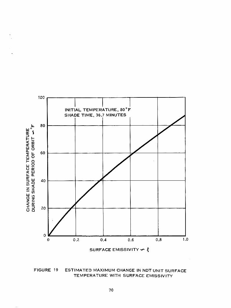
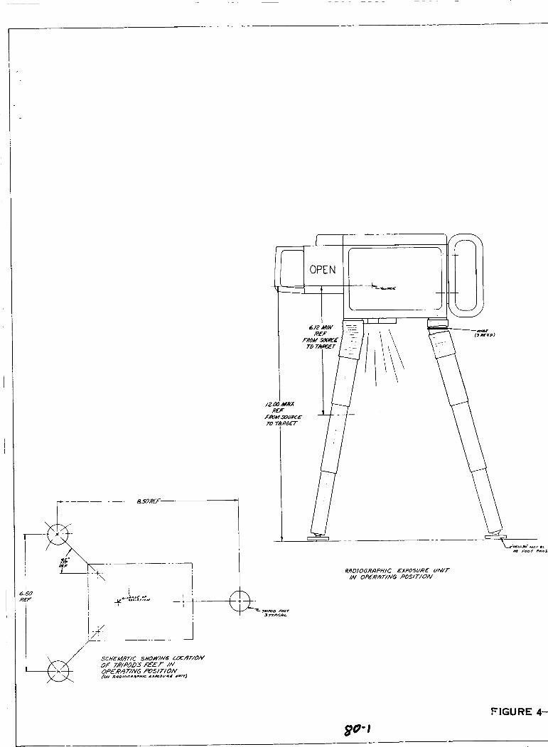
Interrelationship of Various Aspects of Space Exploration Various Possible Vehicle Configurations Meteoroid Protected Wall Structures EB Welded Self-Aligned Wal l Joint Modified Joint for Ultrasonic Inspection Hermetic Seal for Telescoping Section Joint Cutaway View of Pyrobraze Tube Coupling Unit Exotherm/Adhesive Pad Package for In-Space U s e Proposed Adhesive System for In-Space U s e Meteoroid Puncture and Repair Block Diagram 1 - Eddy Current Unit Rompas Inductest FC300S Frequency Oscillator - Inductest FC3OOS Dwg No. ES21-1030 - Rompas Ultrasonics Differential Amplifier - Inductest FC300S Dwg No. ES21- 1031 Rompas Ultrasonics Block Diagram I1 - Ultrasonics Unit Sperry Reflectoscope UCD UCD Verticle and Horizontal Schematic UCD Power Supply Schematic Block Diagram I11 - In-Space Nondestructive Testing Ultrasonic - Eddy Current Unit Radiant Heat Flux From Sun and Earth Incident to the Concave Surfaces of an Earth Orbiting Cylinder (Tangent to Orbit) Radiant Heat Flux From Sun and Earth Incident to the Concave Surfaces of an Earth Orbiting Cylinder (on Radius of Earth) Estimated Maximum Change in NDT Unit Surface Temperature with Surface Emissivity Proposed In-Space NDT Unit Combined Schematic of Ultrasonic- Eddy Current Control Panel Chest Pack - External Assembly Radiographic Exposure Unit Chest Pack - Internal Assembly In-Space Inspection Proposed Probe Concept Multiple Head Probe Concept Back Scatter Radiation Survey
- 3
8 10 10 10 10 16 17 18 22 5 3
54
55 57 58 59
61
67
68
70 75 77 79 80 81 83 84 88 97
i i
I Table
I I
I1
111
IV
V
VI
VI1
VI11
LIST O F TABLES
Title
U It ras on ic Equipment Instrument Survey
Rating Potential - Ultrasonic Units
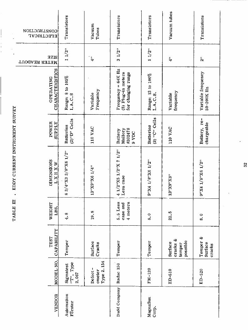
Eddy Current Instrument Survey
Rating Potential - Eddy Current Units
Radiographic Inspection Unit Survey
Rating Potential - Radiographic Units
Specific Characteristics of Ytterbium 169
Advantages and Disadvantage of 3 Major NDT Techniques
Page No.
28
29
32 ,33
34
38
39
41
42
i i i
1.0 INTRODUCTION
With the Gemini program nearing completion, and the lunar oriented Apollo program already under way, studies fo r programs considering longer life duration in orbit such as the "Manned Orbiting Laboratory'' (MOL) are either in process o r complete. These studies have resulted in several conceptual designs for extended duration space stations, all of which will, by necessity, be considerably larger than any to date. Because of size most of these space stations will have to be at least partially fabricated in the terrestial space environment. In-space fabrication studies, design and actual construction of in-space fabrication tools, (electron beam welders, minimum reaction power tool, etc) and space tool operation development are also either in process or nearing completion. Initial feasibility use and experimentation of these tools in-space will be accomplished on the Apollo Applications program. The products of these initial in-space fabrication experi- ments will be returned to earth for fabrication quality evaluation and determination of experiment success. Although mandatory from both an astronaut safety and structural integrity standpoint, on-earth inspection will obviously not be possible with actual in-space fabrication. The necessary in-space inspection concept must therefore be thoroughly ex- plored. Nondestructive testing tools and techniques for in-space applications must be developed. This development effort must parallel the development of fabrication tools for space use if any significant degree of success is to be expected in the development of large manned orbiting space stations. Unfortunately little effort has been concentrated in this area to date. In addition to fabrication inspection, in-space nondestructive testing, equipment will definitely be required to determine the extent of space damage, (i. e . , meteorite collision, potential docking damage, potential dam age resulting from hard lunar landings, etc) and to determine the quality of subsequent damage repair. Other immediate and realistic applications of nondestructive equipment in space programs include areas such as preventive maintenance "in-space", medical use, and scientific research aid.
~
I
I
This program, "Nondestructive Testing for Space Application, Feasibility and Preli- minary Design Study", has been conceived through recognition of the above indicated re- quirements, (i. e. astronaut safety, space station structural integrity analysis and repair, "in-space" preventive maintenance, in-space medical use, and scientific research aid). The overall objectives of this program are to study and evaluate present and future space station concepts, structure, fabrication techniques, and potential in-space problem fo r the purpose of defining as specifically as possible present and future requirements of nondestructive testing in the space environment. Also an objective of this program is the preliminary design and prototype construction of applicable nondestructive testing equipment oriented toward the in-space utilization as defined by the study phase of the program. The scope of the preliminary design and prototype hardware construction includes consideration of all the various problems encountered when considering in-space applications, such as human engineering and materials-space environment compatability. It is expected that the results of this program will sufficiently define flight hardware re- quirements and problem areas to enable design and actual construction of flight hardware.
space damage
1
This report covers a three month Phase I, "Fabrication Study and Preliminary Design" effort of the total program. The period of performance was from 1 July, 1966 to 1 October,
effort is reported under the following major categories: I . 1966. All effort in this phase was oriented toward requirements of NDT in-space. The
Literature Survey Fabrication Technique Study Damage, Repair, and Preventative Maintenance Study Other Application (i.e. Medical, etc.)
NDT Method Selection Multiple Selection Single Selection Ultrasonic Inspection Eddy Current Inspection Radiographic Inspection
Preliminary Design Concept Component Analysis Qualified Components Redundancy Ultrasonic - Eddy Current Integration and Simplification
Preliminary Thermal Analysis General Ultrasonic-Eddy Current Unit Radiographic Unit
Preliminary Vibration Analysis General Hard, Soft, Mount Considerations
Packaging - and Human Engineering Single-Dual Unit Concept Ultrasonic -Eddy Current Conceptual Design Radiographic Conceptual Design
2
Probe Design Multiple Head Concept Finger Tip Concept
Concept and Design Evaluation Testing U1 trasonic s Eddy Current Ultrasonic -Eddy Current Package Radiography Radioisotope Package Operation NASA-MSC Demonstration
It should again be emphasized that all above categories a r e "Space-Oriented".
3
2 0 TECHNICAL DISCUSSION
2.1 Literature Survey - In-Space NDT Requirements
Increases in space flight activity, mission duration and space vehicle size that have progressed from Mercury to Apollo programs all point to future activities which will involve orbiting space laboratories, lunar landings and bases, orbital launch facilities and eventually interplanetary travel. The space vehicles necessary for such missions soon exceed the imposed aerodynamic restrictions of vehicle launch. To overcome these restrictions, both NASA and the A i r Force are currently developing in-space fabrication techniques for expandable sectional space structures.
While it is true that completion of specific mission objectives is a measure of success, astronaut safety is yet the most important single factor in the space endeavor. The high reliabilities that are presently established on earth prior to launch cannot be sacrificed by an in-space welded o r brazed joint which is not inspected for quality and reliability. With these requirements it is imperative that techniques such as current nondestructive testing be adapted for in-space use to perform these inspections,
The use of nondestructive testing equipment is not restricted to inspection of primary construction. Potential hazards such as space damage (i. e. Meteorite penetration) and even accidental damage (i. e. mismatch docking damage) must be considered. NDT equipment would be invaluable in assessing the extent of such damage and the quality of rritsrr sub- sequent repair. Nondestructive inspection is required to provide the needed reliability assurance. Results of numerous research programs conducted in the past ten years have indicated that degradation and deterioration of some materials is to be expected in the space environment during long duration missions. Nondestructive inspection equipment will be invaluable in evaluation of this degradation as preventive maintenance. As previous- ly indicated, the same NDT equipment can be extended for use in such areas as medical diagnoses and scientific research aid.
This literature search was performed to define specific requirements of in-space nondestructive testing and to establish associated guide lines. More specific equipment requirements have been established by considering proposed fabrication techniques and expected defects that the equipment must be capable of determining. The study has been categorized in four major areas: (1) primary construction (2) damage and repair and (3) preventive maintenance, and (4) medical and other uses. In considering primary construc- tion, in-space fabrication techniques were reviewed coupled with material investigations, proposed space station configurations, structures, and joint design. The interdependence of these areas and their effects on in-space nondestructive testing equipment are clearly demonstrated in Figure 1. Potential damage modes were investigated and the use of in- space NDT equipment for accurate damage analysis is demonstrated. The utilization of fabrication techniques in conjunction with NDT for repair operations are also included. Effects of the space environment on degredation of materials and use of NDT to assess
4
SAFETY AND n REL lABl L lTY
FIGURE 1 . INTERRELATIONSHIP OF VARIOUS ASPECTS OF SPACE EXPLORATION
5
the extent of these effects i s considered.
I '2.1.1 Primary Space Construction
Proposed Space Station Configurations
The broad mission definition of continued exploration of space i s used as a starting point for primary space station construction. Design of future space stations must he considered, with few exceptions, as still conceptual. There designs a re expected to be modified as the effects of the space environment on specific missions, physiological, psychological, and the biological requirements of man-in-space are more clearly defined. A program oriented toward such definition is the Manned Orbiting Laboratory (MOL). The prime mission of MOL is to investigate the behavior and capabilities of man-in-space for extended duration flights. The results of MOL experiments, specifically the effects of zero gravity on man for extended time periods, will strongly influence future space station designs
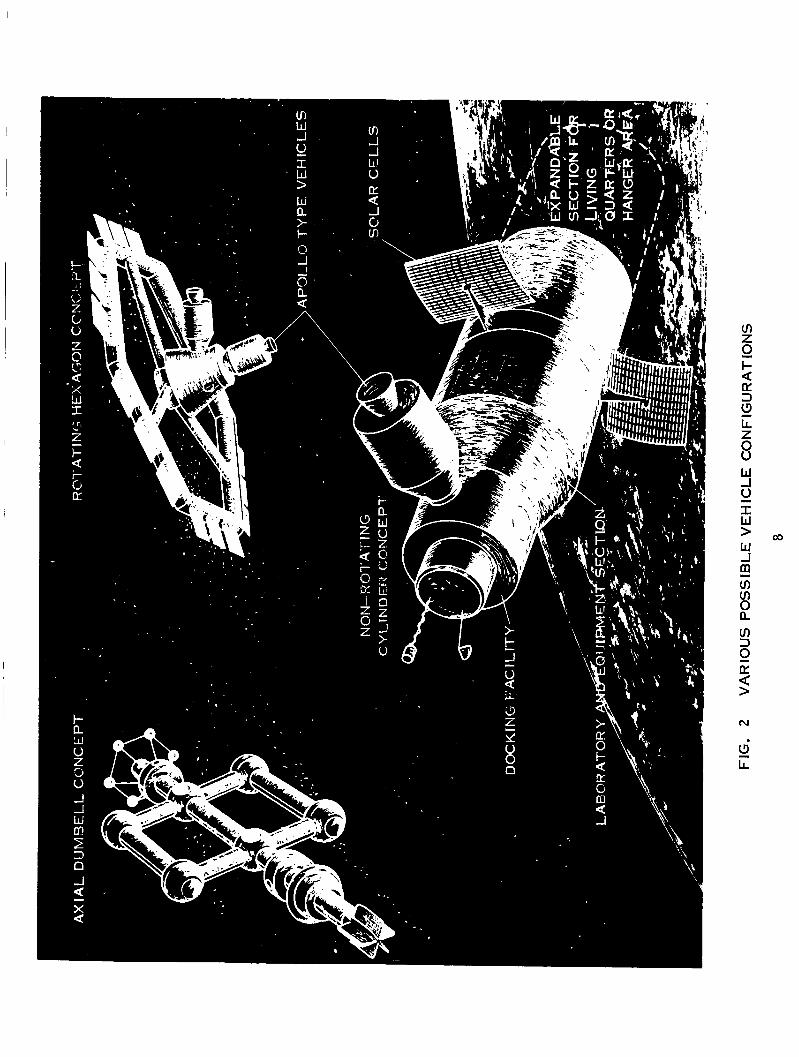
Two configurations for large f i rs t generation space stations are considered. These are the cylinder and the spoked toroid (or hexagon). If mission requirements do not in- clude a need for artificial gravity, the cylinder configuration will undoubtedly be selected. The toroid (or hexagon) configuration will be considered only i f it is necessary to provide artificial gravity. This will be accomplished by rotation of the toroid at a speed sufficient to create the necessary tangential force which will create the sensation of gravity.
"In-orbit" considerations impose only minor geometric restrictions on non-rotating space stations. Geometry will be dictated by compatability with the launch vehicle which restr ic ts shape to a cylinder. The first MOL, the only space station in the hardware stage, will be a cylinder with a 10 feet diameter and a 41 feet length which will conform to the Titan 3C launch vehicle. The primary cylinder will be of rigid wall construction. Should additional volume be needed for experimentation o r hanger area, an expandable structure may be used. Work done by the USAF during the past 4-5 years has shown that expandable structures a re currently within the state-of-the-art capabilities of industry,
Pr imary construction (in-space fabrication) on this type of space station i s expected to be very limited. Ppssible in-space fabrication and subsequent in-space NDT includes attachment of solar cell panels, antenna structures, and probe booms to the exterior of the cylinder, Experiments will consist of construction and inspection of large structures that cannot be launched in final conliguration.
A s ear l ier stated, if i t is deemed necessary to provide artificial gravity, the space station must be rotated. be more than 60 feet f rom the center of rotation. During a study by NASA - Langley Research Center, configurations Considered included cross, rim, flywheel, tumbling cylinder, spinning cylinder, in-plane modules and axial modules. Based upon inherent stability,
Human factors studies have indicate that mnjor work :ireas must
. size and usable space, the configuration considered optimum was the flywheel, (spoked toroid o r hexagon). A totally expandable flywheel shaped space station w a s considered but subsequently discarded due to; (1) equipment would have to be stored in the hub during
and I I
I I
. launch and moved to the r im after inflation to provide the necessary spin stability, ( 2 ) insufficient micrometeoroid protection could be provided.
I
A partially rigid-partially "inflatableff hexagon configuration w a s initially considered in a study of rotating space station configurations, and an applicable systems analysis conducted by North American Aviation for NASA-LRC. The final design was an all rigid hexagon configuration with center hub and spokes shown in Figure 2. The six sides of the hexagon can be hinged and folded into a cylinder where the axes are parallel to provide compatibility with launch. The sides would automatically be deployed once in orbit. The hub has facilities for a zero gravity laboratory and for re-entry vehicle docking. The spokes are telescoping walkways o r laboratory areas
I The feasibility of a semi-rigid ffexpandable'f (telescoping) structure has been demon- strated by the Martin Marietta Corp. in a contract with the USAF. Each section of the hexagon is expected to have its own power supply and environmental control system. The sections will be separated by air locks. In the event damage occurs to any individual sec- tion, the damaged section can be isolated from the remaining station until repairs are completed, inspected and qualified for use will be more extensive in this configuration than that of the cylinder.
In-space assembly and subsequent inspec tion
One of the more critical problem areas of large space stations of long duration is that of leakage. Hermetic sealing of space station interfaces is a recognized necessity. Methods of joining these interfaces have already been studied by NASA and the USAF. The six corners of the hexagon require hermetic seals as will the telescoping interfaces of the spokes. Hermetic sealing will also apply to the attachment of spokes for the rim. These joints are structurally loaded members and will require subsequent in-space NDT to assure astronaut safety .
I To provide additional space "in-space", the A i r Force has proposed the use of non- rigid and/or semirigid expandable structures. It i s expected that some in-space fabrica- tion and subsequent NDT inspection will be required to successfully accomplish this goal. The current NASA approach to additional space station volume i s to utilize spent stage fuel tanks. An airlock is presently being developed to couple the spent S-4B stage to an Apollo spacecr'aft. Little primary construction is expected on the S-4B stage with the availability of the Apollo hardwnrc>. E:xtcnsi\.c. construction inside t h e fue l tank is however foreseen. Such construction ng:iin indica1c.s the> nced for in-space fabrication and sub- scqucnt inspection. station i s also under consideration.
Linking several S-4B stages together to form a large complex space
Two configurations have hecn proposcd that require extensive in-orbit fabrication and subsequent inspection. They arc r*c>fcrrcd t o as the "extended dumhell" and a modification known as the "Pseudo - C;eogr.:it.it:~tion:il Vchiclc". The extensive fabrication cmd inspection
arc due primarily to the large size and complexity of these proposed concepts.
Space station configurations a re influenced primarily by mission requirements, how- The ultimate configuration ever materials and fabrication techniques also have an effect.
will indirectly affect the required nondestructive testing through structures, joint design <and fabrication techniques as shown in Figure 5. The structures concepts most often encountered in primary orbital construction are walls, tubing duct work, and external appendicies, (i. e. antenna supports, solar cell panels, radiators, etc. ).
Walls of a space stations have the same broad functional requirements of any typical wall in that it must contain the desired environment while protecting the occupants and contents from an undesirable environment. This containment function in-space has more rigid requirements in that it must be hermetically sealed. Any such structure fabricated in-space must also be inspected in-space if the required seals and subsequent safety a r e to be maintained. The above requirement has been demonstrated by the high resupply cost of environmental fluids to large, long duration space stations. Although there is no gravitational loading in orbit, structural requirements are imposed by internal pressuriza- tion, thermal cycling, possible artificial gravity, dynamic aspects of a manned space station, launch loads and on-earth assembly. Protection must be provided in the space environment from meteoroid, solar radiation and charged particle radiation. The walls are also to be used for radiant heat dissipation to the near infinite heat sink of deep space and for absorption of heat energy due to solar radiation.
The simplest structure consists of a one layer sheet but imposes extreme weight penalties when considering meteoroid protection and structural loads (buckling) during launch. The addition of stringers to thin materials has been proposed, but this would solve the buckling problem only.
Hypervelocity particle impact studies have shown that a double wall construction is approximately 3 times more effective than an equivalent single wall structure for meteoroid protection. The proposed "Whipple bumper" is a two layer structure with an outer layer 1/12 the original single wall thickness and the inner layer 1/4 the original thickness. The outer layer produces the effect of fragmenting the impacting meteoroid and spreading out the debris over a larger area as it penetrates and strikes the inner wall. The meteoroid protection afforded by the "Whipple bumper has completely eliminated the single sheet wall structure concept. The structural requirements a re met by using honeycomb, corru- gation, stringer o r t russ configuration. Honeycomb i s not considered an effective "Whipple bumper" due to the ch'anneling effect of the cell structure. An additional third layer must I>e utilized for the outer meteoroid wall. Thc space between walls are to be filled with in- sulation material which wil l aid in thermal control. Radiation protection requirements are c.onsiclci.cd minoi. when c o m p r c d to structural nnd mctcoroid protection rcquirc nwnts of
METEOROID BUMPER
PRIMARY LOAD STRUCTURE
INS U LATlON
PRESSURE SHELL
STIFFENER PRIMARY LOAD S TR U CTU R E
FIGURE 3 METEOROID PROTECTED WALL STRUCTURES
RADIATOR TUBE
I NSU LATlON METEOROID BUMPE
E B WELD HONEYCOMB
PRESSURESHELL
FIGURE 4 E B WELDED SELF ALIGNED WALL JOINT
PRESSURESHELL ULTRASONIC
’ METEOROID
A -MC3DIFIED JOINT FOR UI-TRASONIC B - ilERMETlC SEAL FOR TELESCOPING INSPECTION SECTION JOINT
FIGURE 5
10
~ 2 space station in low (500 nm.) earth orbit and inclined at less than 30°. levels a t these altitudes a re the result of incident charged particle capture by the magnetic field of the earth at higher altitudes interplanetary travel, protection from the intense radiation of solar f lares becomes a prime design consideration for a significant portion of the space station wall structure. (Protection of the entire space station leads to excessive weight penalties). Thermal stresses due to heat flux variations in orbit will have a significant effect on wall structure design, and hence upon in-space fabrication techniques and subsequent inspection. Allow- ances must be made for thermal expansion and contraction of the outer layer. A "semi- floating" outer wall is common in most concepts of wall structures. The three structures shown in Figures 3 and 4 have the same common characteristics: (1) internal pressure shell (2) reinforcements to prevent buckling, (3) meteoroid bumper (4) non-rigid support between inner and outer layers and (5) thermal insulation. Techniques for damage repair of these structures is currently under study, however in-space nondestructive test tech- niques must also be developed to assess the reliability of the repair to assure astronaut safety.
Low radiation I
I I
(The Van Allen Belts). However, when considering
Tubing and duct work systems proposed for space stations are essentially the same as for earth use. However, closed environmental system imposes a much more stringent requirement because of sealing aspects. Tubing and duct work occur primarily in environ- mental control systems, propulsion systems and power generating systems. Tube joints are expected to occur more frequently as space stations become more complex. These joints may be brazed or welded depending on the specific configuration. If this work is accomplished in-space as will be necessary in many instances, the joint must also be in- spected in-space if any quality assurance level is to be expected. Space stations such a s the extended axial dumbell, which have atomic power stations and environmental fluid storage tanks located romote to the main living quarters, will require extensive tube and duck work joints and attendant high reliability.
The structure of external appendices is expected to be similar to counterparts on earth. In non-rotating space stations, load requirements will essentially be non-existent except for on-earth assembly and transportation. If used on a rotating station, the artiiicial gravity will not exceed one "g" due to human considerations, and design require- ments a r e not expected to exceed those on earth. However the possibility of damage on lift off (heavy vibrational loads) is a definite factor, therefore a means of detecting potential damage such as a nondestructive test instrument must be provided,
Applicable references: 8, 44, 14, 13, 2, 12, 32.
Materials for "In-Space'? Use
Although a large variety of materials are utilized in present day spacecraft, aluminum and titanium are the major structural materials. The Mercury and Gemini pressure vessels were of commercially pure titanium (AMS 4901) skins stiffened with titanium stringers o r coriwgations of welded construction, The pressure vessel of the Apollo command module
11
is aluminum honeycomb of 2014 and 5052 alloys. Most secondary construction is also of titanium or aluminum alloys. adapter module due to weight considerations but is not considered a principal material for man occupied sections due to a possible explosion hazzard from meteoroid impact. As this alloy is a thorium bearing alloy a potential astronaut communication problem exists in that the thorium could possibly produce radiation and hence interfere with communication. Stainless steel (PH15-7 Mo) is used as a structural support material for the ablative heat shield on the Apollo command module. The service module of Apollo i s a1 u m i nu m honeycomb .
I Magnesium (HK 31A) i s used extensively in the Gemini
.
Investigation of secondary structures, power systems and propulsion systems reveals a myrid of high temperature, high strength o r corrosion resistant materials depending on the specific applications.
Due to its strength to weight ratio, and state-of-the-art fabrication, aluminum is present- ly the principal material being considered. Other materials that will also occur frequent- ly are titanium, stainless steel and magnesium. It is expected that as the state-of-the-art of materials development increases, other high strength-to-weight ratio materials such as beryllium and fiber reinforced materials will see extensive use in space oriented systems.
A review of material thicknesses to be encountered in in-space fabrication indicated that approximately 90% of the cases would have wall thicknesses less than .125". The limited number of heavier sections are used in structural reinforcements and radiation protection.
Applicable references: 2, 14, 13, 24, 6 , 23.
Joint Designs Proposed
Joint design requirements can be divided into three areas - structural, hermetic seal and attachment. The specific joint design o r configuration for hermetic seals or structural requirements that are to be used for in-space fabrication and assembly will depend on space station design, wall structure, material, fabrication technique and inspection technique. In attachment operations where the joint strength is not of prime consideration, the design guide will be simplicity.
For first generation space station, the primary use of in-space fabrication facilities will be hermetic sealing. As stated earlier, because of both safety and atmosphere replenishment costs, these in-space fabrications must be inspected, Since this will occur essentially in rotating stations, the joints will also be structurally loaded. Figure 5B represents a conceptual joint that is contemplated for use in the hexagon configuration studied by NAA. The triple layer honeycomb wall structure has been modified to provide self-aligning facilities for the meteoroid bumper and the pressure shell. A deficiency of this design is the middle layer which is not joined, The stiffness of honeycomb i s such that both skins can be used to carry the load of internal cabin pressure. It will be necessary
1%
. to modify this concept to include either a method of joining the middle layer o r a transfer of the middle layer load to the pressure shell. Similar type modifications will be needed for the two other wall structures shown in Figure 3. Electron beam welding appears to be the ideal joining method for this type of joint.
.
The sealing method for the telescoping joints in the expandable structure developed by Martin Marietta is an internal bladder and an 0 ring. A metallurgical bond is, however, preferred for a better hermetic seal. Figure 5B illustrates the Martin proposed joint design plus a preplaced placement of braze alloy and exothermic heat source. The joint is further modified in Figure 5A to provide capabilities for ultrasonic inspection. The pre-engineered aspect of the exothermic brazing process readily lends itself to a joint of this nature.
Attachment type joints could be mechanical fastened, E. B. welded or exothermically brazed. The use of organic adhesives, for external applications on long duration space stations ,are limited due to deterioration in the space environment. Possible damage to the solar cell panels prohibits extensive astronaut activity in their immediate vicinity, how- ever should such damage occur, a readily available in-space non-destructive test instru- ment would be invaluable.
An evaluation of joining systems for in-space fabrication was performed by Hughes Aircraft Co. fo r NASA-MSC. The following systems were evaluated:
1. 2. 3. 4. 5. 6. 7. 8. 9.
Electron beam welding Resistance welding Thermochemical brazing Adhesive bonding Solid state joining G a s fusion welding A r c welding Focused sunlight welding Laser welding
The systems are listed in decreasing order of probable in-space success. The cr i ter ia for evaluation was materials, design philosophies, logistics of currently contemplated missions,and human factors. The two systems selected by Hughes with the highest poten- tial for adaptation to in-space fabrication are electron beam and resistance welding. The program is continuing with feasibility demonstrations and reliability tests in simulated space environment.
13
Although the study recognized the potential of resistance welding for space use, there is no current hardware development. While the system has several advantages, there are several major drawbacks. Short electrical pulse times that are characteristic of resistance welding result in a minimum of total power expenditure consistant, with good efficiency. The fusion zone during lap welding is completely surrounded by solid metal which reduces the problems of zero gravity and hard vacuum. Main disadvantages of resistance welding are the clamping forces necessary to provide contact and the inherent restriction to only lap type weld joints. The system is very adaptable for welding of intricate electronic systems but not hermetic seals or the structural members of large space stations.
'
Narmco Research has been contracted by the A i r Force Materials Lab of WPAFB for development of exothermic brazing in vacuum. The object of the program was to design, fabricate and evaluate vacuum bonded joints of stainless steel, titanium, aluminum, and magnesium alloys using an exothermic heat source. A demonstration space station module was assembled and brazed remotely in a vacuum. The program consisted of evaluation of exothermic heating systems, application of exothermic heat to various base metal alloys, joint design and evaluation module design, fabrication, and evaluation. The advantages of the system are: (1) short heating times (5 to 45 seconds from ignition of exotherm to solidification of braze alloy) (2) complete remote control capabilities (3) light weight joints with relatively high strength (4) good hermetic sealing, and (5) totally pre-engineered for a minimum of in-space work. Principle disadvantages of the system a re (1) close tolerances are needed for braze joints (2) the potentially dangerous reaction of the exotherm in a pure oxygen environment, and (3) poor brazeability of aluminum and magnesium alloys. Lap shear tensile specimens of 347 stainless steel and A-11OAT titanium exothermically brazed had strengths comparable to ordinary vacuum brazed specimens. Exposure of titanium to the exothermic reaction causes near complete loss of ductility (a decrease from 20% to 1% elongations). This problem could be minimized by using a thin metallic interface between the exotherm and titanium.
Types of joints considered in the program were the joining of structural members, sealing of openings, and the rigidification of locating devices. Preliminary design was based on ease of fabrication and joint strength but modifications were made for brazing and exothermic heating. The nine joints designed, brazed and evaluated are listed below:
Type Description
I I1 III IV V VI
VI1 VI I1 Ix
Butt joint, thin walled tube Butt joint, thick walled tube Door hinge Telescoping joint, thin walled tube Ball joint Swivel joint Tee joint, tube to tube 60' butt joint, tube to tube Door seal
14
All joints were successfully brazed with load carrying capabilities greater than the base material.
The space station module fabricated w a s very similar to the NAA hexagon concept shown in Figure 2. The module consisted of six type 8 joints, three type 7 joints and three type 4 joints. Assembly of the module included placement of the braze alloy, exotherni heat source and ignitor wires . Brazing was done in a vacuum of 3 X torr . The total pre-engineered aspect of exothermic brazing is illustrated by the fact that the only opera- tion necessary for brazing,once the module was in the vacuum chamber,was the operation of a switch. All joints were successfully brazed except one where ignition failure occurred. Due to the success of the program the A i r Force feels exothermic brazing is now ready for tests in space test beds such as the MOL.
Independent development by Narmco has lead to a commercially available permanent tube connector under the trade name of "Pyrobrazef'. The totally prepackaged unit is shown in Figure 6. Modifications necessary for space use have been made by Narmco and the unit has been successfully demonstrated in a simulated space environment.
In work recently completed for the A i r Force but as yet not yet published, Narmco has adapted the exothermic heat source for adhesive bonding in-space. The system uses a single-component thermoplastic as the adhesive that is heated to bonding temperatures by the exothermic reaction. systems developed by NCR is its capabilities of bonding to substrates that are at low temperatures. Figure 7 is the Narmco system adapted to a mounting bolt.
The principle advantage of this system over the two-component
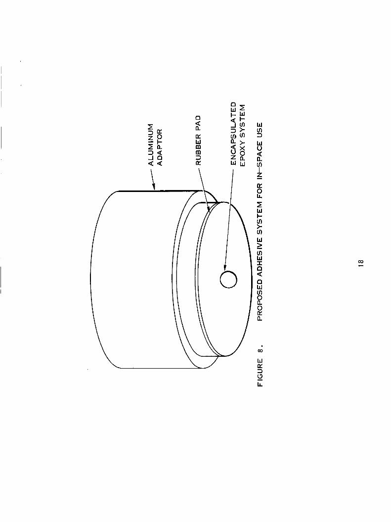
The National Cash Register Coo recently completed a program for the A i r Force on the development of a capsular adhesive system that has potential use in a device for attach- ing an astronaut to an extravehicular activity (EVA) work site. Design goals w e r e an ad- hesive for use in space that would bond to a variety of substrates with a strength of 100 psi and within 10 seconds of applying an activation force of 2-5 pounds. Two systems w e r e developed with very promising results but more effort is required to evaluate in-space storage life. The encapsulated system is attached to the center of a pad as shown in Figure 8. Six pads can be stored in a dispenser unit which remains mechanically attached to the pad and becomes an integral part of the astronaut-to-work site attachment complex. The system has also been proposed for structural bonding hermetic sealing, meteoroid damage repair and astronaut space suit repair kits.
Although not directly applicable, a fabrication technique that has already been in orbit (Gemini 11) is the space power tool designed and developed jointly by Mar t in Marietta and Black and Decker. Unfortunately the experiment was cancelled. impact type minimum reaction wrench capable of torques of 400 inch pounds, operated by self -contained Ni -Cd batteries
The power tool is an
15
w In 3 w u
In I z a: 0 LL w
2 -
s u 2 2 a
Ill
m w I a \ 2 a: w I I- O X W
2
a
b
W a: 3 (3 G
n 2 oc W
3 oc
rn rn
W m 3 W 0
m I z
w
if
c -
2 W I- m > m W
m W I 0 < W m
0 oc a
2
n
B
co
W LT 3
LL 2
The most extensively studied and developed system for in-space fabrication is electron beam welding. A 2 1/4 year study w a s conducted by Hamilton Standard Division of United Aircraft Corp. for the USAF to determine design guidelines for electron beam welding equipment and techniques for variable environment (in-space) use. This study was completed in February, 1965. Hamilton Standard w a s then contracted by NASA Manned Spacecraft Center in June, 1965 to construct a hand held E. Bo gun. This specific gun was success- fully demonstrated at a simulated altitude of 73 miles in Hamilton Standard's man rated space chamber in September, 1966. The gun has a rated power of 1 . 5 KW and an accelera- tion voltage of 15 KV. This is capable of penetrating approximately 1/4 inch aluminum at a welding speed of 15 inches per minute.
Westinghouse has been contracted by NASA Manned Space Flight Center to design and build a self-contained electron beam welding machine. The equipment is designed to oper- ate from its own battery pack. This equipment is scheduled for delivery to NASA in the latter part of 1967.
The high energy of the electron beam and the small fusion zone provide excellent efficiency. E. B. welded butt joints have strengths equivalent to base metal due to the small heat effected zone. Although the metallurgical bond resulting produces true hermetic seals, subsequent nondestructive testing for safety purposes is still required.
Nondestructive inspection instruments to be used for the detection of defects depend on (1) geometry of hardware (2) material, (3) geometry of defect and (4) the position of defect in that geometry. Hardware geometry has been illustrated in the sections on struc- tures and joint design. With only minor modifications, these structures and joints can be inspected with near conventional equipment. Materials in space stations have had extensive use on earth and should impose no additional restrictions on NDT equipment in-space. The geometry of defects is not expected to be substantially different from on-earth defects, Basic equipment capabilities for in-space NDT are met by commercially available equip- ment, although this equipment must be redesigned to cope with the human engineering factors in the environment of space, and the vibrational problems encountered during launch into space. '
Major characteristics of the space environment expected to effect joining operations a r e the hard vacuum, zero gravity and temperature extremes. These characteristics should have limited effects on electron beam welding. Currently commercial E. B. equip- ment operates in a vacuum of tor r or better. A vacuum of to tor r is not expected to adversely effect the weldment. The main effect expected is possible changes in surface energies when absorbed gases are removed. This effect will be small because the high temperature of E.B. welding has a normal tendency to remove the absorbed gases during the welding process. The hard vacuum will increase sublimation and vaporization. This could cause porosity in extremely "hard" vacuums, and possibly a spewing of the molten metal if gas evolution is rapid. Zero gravity effects of the space environment are expected to have a negligible,if any,effect on EB in-space welding. This has been demon- strated at Hamilton Standard by inverted E.B. welding (i.e. directing the beam upward
19
I to the workpiece rather than the conventional downward direction). Workpiece temperature I variations however will effect optimum weld parameters. If the workpiece temperature
has significantly changed between E . B. parameter determination and actual welding, an over or under power situation will occur affecting the weld quality. This situation is possible due to effects of heat flux variations imposed on an orbiting vehicle.
'
A common defect found in welding processes is porosity. This is expecially true in the case of E.B. welding of joints where total penetration is not required, (i.e. lap joints). Vacuum effect of the space environment may increase this porosity potential. Weld bead cracking, longitudinal and transverse, can occur if weld parameters are not optimized. Beam diameter of the E.B. welding process is sufficiently small to make base metal "fit-up", and tracing of the weld joint a potential problem. Improper fit-up o r a joint "miss" (which is highly possible) would obviously result in a totally unbonded area. Defects in in- space E. B. weldments are in general expected to be the same as on-earth weldments (i. e. cold shuts, porosity, bead cracking, lack of penetration, etc.). Initially, until space effects on E. B. welding and human factors (EVA) are better understood, it is expected that defects in-space will be more numerous. It is essential that a means such as nondestructive testing in-space be provided to locate and assess the effect of these defects.
Structural braze joints are expected to be mainly lap joints with close tolerances. The strength of a braze joint is derived from large shear areas. Characteristic on-earth brazing problems are the lack of flow and the lack of wetting. Flow is controlled by capillary action and surface wetting characteristics in the joint and is not expected to be effected by zero gravity conditions of the space environment. Hard in-space vacuum is expected to have a greater effect on brazing than on welding due to the strong dependence of brazing on the wetting phenomenum and surface energy effects. This is the result of removal of sur- face oxides and contaminants (of which the wetting action and braze flow are a function of) by the hard in-space vacuum. The ultimate result of brazing in the hard vacuum of space then may be excessive flow and a deficiency of braze alloy in the joint. Depending on braze alloy used sublimation and vaporization may also occur causing porosity. Close tolerances required of a braze joint will cause most of the defects to appear to be two dimensional (as cracks). Braze joints, as in the case of most in-space fabrication, will require nondes- tructive testing to achieve the necessary reliability confidence level Ultrasonic techniques can best reveal subsurface crack-like defects. Eddy current techniques are also applicable with thin material c ross section.
Structural adhesive bonds and seals are expected to have defects very similar to braze joints. Eddy current inspection techniques are not applicable to this type of inspection because of the low conductivity of the organic adhesives. Ultrasonic inspection then is the only reliable NDT method of establishing organic bond integrity.
20
. 2 . 1 . 2 Repair
It is expected that accidents, such as meteoroid puncture o r docking mishaps, will occur even though they are minimized by extensive on earth engineering and reliability measures. When an accident does occur however, on-board fabrication techniques can be used to make repairs. Nondestructive testing equipment can be used for accurate access- ment of the damage and establish repair reliability.
Meteoroid Damage
I .
,
I l The effects of meteoroids on spacecraft are to be divided into two categories, erosion
and puncture., Meteoroid environment in an earth orbit is an inverse log-log relationship between meteoroid mass and flux. The large number of micrometeoroids a spacecraft encounters causes a gradual erosion and degradation of the surface coating and material. The impact of "large" meteoroids (10 to 100 mils in diameter) can create emergency situa- tions. Spacecraft wall structure design is based on a "trade off" between meteoroid protection and weight. Knowing the penetration characteristics of the structure, the meteoroid environment and the space mission, a probability of near zero punctures can be given. Even with the high prdxbili t ies of no puncture that manned spacecrafts are now designed to, I'sufficient evidence exists at this time to consider meteoroid penetration, when and if it occurs, as a major emergency, rather than the minor inconvenience of locating the leaks.'I (ref. 8.) The ability of a spacecraft to complete its mission will be seriously jeopardized unless repairs are made and nondestructively inspected.
Consider a double wall, semi-monocoque structure that is filled with a low density foam insulation struck by a high velocity meteoroid. Impact with the outside wall causes a small (1 1/2 to 2 times meteoroid diameter) neat hole. The meteoroid and hole debris are broken into many small particles. As these particles hit the insulation they are generally stopped if it w a s initially a small meteoroid. large the results are very disasterous. Impact of the many small particles with the insu- lation material produces a pressure pulse that is almost an explosion. The pulse is trans- mitted to both the inner and outer walls, and produces an extremely destructive effect on the inner wall. It literally "ripsll a hole in the inner wall that is several hundred times larger than the hole in the outer sheet. This inner wall hole is characterized by jagged petaling metal and large r:idial cracks. (See Figure 9.) The extent of the pressure pulse damage to the outside wall has not been thoroughly studied but it could be of the same magnitude ;is the inner wall. The next result of this type of construction is either no hole in the inner wall or an extremely large hole.
However, if the meteoroid w a s
The immediate results of meteoroid penetration are (1) a pressure pulse in the interior of the cabin, (2) potential dtwxidation of the cabin atmosphere, (3) combustion of cabin material and ( 3 ) meteoroid and cabin wall debris injected into the cabin, One of the most serious results are the radial cracks that occur in the inner wall (pressure shell). Thc shell will be stressed due to intc>rnal pressure and the cracks could initiate a catastrophic failure of the wall. Structuixl supports hetu.een the walls. such a s stringers, honcycomh
21
W a: 3 I- u z 3 n n I
0
W I- 8 r” LL 0
W U 3 I- u z 3 n n - 0
W I- W
8
or corregution, may tend to minimize this effect somewhat. If complete penetration does not occur, the pressure pulse could cause a bulging of the inner wall, possible cracking and rupture of honeycomb or stringer bands.
Once penetration occurs and before repairs can be made, the puncture must be located and the extent of damqge determined. The location of a 2 to 4 inch diameter hole in the inner wall will not be too difficult provided it is not hidden by equipment o r secondary structures. If it is necessary to locate the puncture from the exterior surface visual in- spection is probably the most effective method for large punctures. Small punctures that cause no,or only smal1,effect on the pressure shell will be more difficult to detect and will create a problem of preventive maintenance rather than an emergency situation. Detection of these small punctures will have to be accomplished by nondestructive testing. Damage analysis of a large punctures will deal mainly with the extent of radial cracking. Any repair operation must eliminate these cracks or hermetically seal them and prevent further propogation. Eddy current NDT equipment can be used to determine the extent of these cracks. Bonds between the inner wall and reinforcement structures may be ruptured by the pressure pulse. This damage can readily be analyzed with ultrasonic NDT equip- ment in space.
Repair of meteoroid puncture damage involves 3 distinct problems. (1) hermetic seal of pressure shell, (2) structural reliability of repaired area and (3) prevention of crack propagation. Hermetic sealing will be essential since the station will be operating on the basis of no resupply. The large dynamic loads of launch will not have to be considered for repair but internal pressurization and possible artificial gravity produce substantial static loads which any repair operation must consider. Cracks can be sealed with organic material but a metallurgical bond is required to prevent propagation if the area of the crack is stressed. Again in-space NDT must be utilized to ascertain the achievement of a complete metallurgical bond in the repair operation. The repaired area compared to the total area of the spacecraft is considered small and the effect on thermal balance will generally be negligible. The low density insulation prevents convective currents of a i r trapped between the walls due to on-earth construction. The repairs in space eliminate the convective air problem and re-foaming should not be necessary.
Repair of meteoroid puncture has been suggested by two sources as involving a kit type of procedure. The damaged material in the area of puncture will be completely re- moved. A pre-cut and pre-contoured plate will be positioned over the opening and electron beam lap welded o r exothermically brazed to the pressure shell. The advantages of E o B. sited ear l ier also apply to repair work. Also of consideration is the use of the E.B. gun as a cutting tool to remove damaged material. Exothermic brazing has the advantage of simplicity of operation. Since repair plates will be totally pre-engineered, the braze alloy and exothermic heat source can also be pre-placed on the plates resulting in a minimum in- space effort. reliability of a true fusion bond.
Adhesive sealing can also be used but will not provide the permanency or
For mission continuation with reliability of the original structure, the repair operation will be critical and inspection will be required to establish the quality and reliability of the repaired joint.
23
* Potential Cracking Damage
Fatigue cracking is expected to become an increasingly important design considera- tion as mission times become longer and spacecraft increase in size. The rotation of a space station to induce gravity will also have a definite and significant effect on fatigue considerations. If fatigue cracking does occur simple adhesive patching to prevent leakage will not be sufficient as crack propagation will occur and reopen the crack. Proper repair will involve reinforcement of the area to eliminate a design deficiency as well as sealing of the crack. If a preventive maintenance procedure is established, (as discussed below) the cracks can easily be detected with eddy current or ultrasonic inspection while repair is still feasible. Repair procedures can then seal the crack with an E.B. weld o r exother- mic braze patch. Structural reinforcements will be critical and NDT inspection of repairs will be mandatory if the mission is to continue, Although the astronaut may not be in any immediate danger without repair-inspection techniques, the cost of their development compared to the cost of "scrubbing" a mission is extremely small.
Structural Damages
Docking of space vehicles is still and will for some time be an intricate operation that requires precision in alignment and vector control. As space activities increase the frequency of docking, maneuvers will increase. The malfunction of a control rocket such as occurred on Gemini 8 and 11 o r pilot e r ro r could cause sufficient damage to place the astronauts o r mission in severe jeopardy. On-board fabrication equipment will be avail- able for repair and NDT equipment can be used for damage analysis and inspection of the repair .
Lunar landings are expected to require the same intricate rocket control as dockings, except the operation will be on a larger scale. Damage of the structural support of a lunar module could prevent take-off unless repairs a r e made. During landing and launch from the moon's surface, rocket exhaust impingement on the surface are expected to se t into motion lunar dust and debris that could cause damage to the module. Damage analysis, repair and repair inspection will again be essential.
Applicable References: 2, 8, 12, 26, 32, 44, 51.
2 . 1 . 3 Preventative Maintenance and Inspection
The characteristics of the space environment that contribute primarily to the deterio- ration and degradation of materials are vacuum, electromagnetic radiation, charged particle radiation and micrometeoroids, Although heat flux variations are important in the space environment they cannot be considered a characteristic of the environment alone. A preventive maintenance program to periodically nondestructively inspect for deteriora- tion is a definite necessity fo r any extended space missions. Principle areas of concern a re thermal control coatings, hermetic seals, and structural joints and materials.
24
I I -
Deterioration of thermal control coatings is the result of a change in the absorption and radiation characteristic (e/a ratio) or a coating thickness reduction due to errosion.
particle radiation contain sufficient energy per quantum to initiate chemical reactions. This may change the chemistry of organic base thermal control coatings and hence change the e/a ratio. Other resultant effects are increase in strength and hardness, decrease in ductility plus variations in thermal conductivity and electrical resistivity. Micrometeor- oids, charged particle radiation, and sublimation cause erosion o r material loss in the space environment. It is conceivable that all of the above changes may be determined through nondestructive eddy current testings .
, . Shorter wave length electromagnetic radiation, up to ultraviolet light, and charged
~
~
Continual nondestructive test surveillance will be required to insure material integrity and astronaut safety. In addition, data generated from this surveillance will be invaluable in improving and/or better selection of materials for the space environment.
Structural adhesives are utilized to bond the ablative heat shield to the vehicle sub- structure. Deterioration of this bond would seriously jeopardize astronaut safety during re-entry. An Apollo type re-entry vehicle docked at a space station for 6 to 8 weeks will be subjected to extremes of the space environment. Heat flux variations and charged particle radiation for these extended periods have strong potential to cause delamination of the heat shield. Nondestructive inspection to determine bond integrity in these cases is mandatory. Techniques currently under development wiil be capable of revealing these "debonded" areas. Cold welding is a potential problem in extreme vacuums. Failure of moving components; valves, solenoids, etc; may be due to either fracture o r cold welding. Radiographic inspection of the interior of the unit would be a valuable aid for in-space "trouble shooting'' and repair.
Long interplanetary missions will initially be launched from an earth orbit ra ther than by direct "lift-off" from earth. For safety and reliability, it may be necessary to inspect critical engine components (valves, tube joints) before final "in-orbit" launch. If failure occurred during launch from earth orbit, repair and inspection will definitely be required before the mission can be allowed to proceed. NDT equipment would be required for an "on-the'spotfTfailure analysis to enable the mission to continue and to aid future design.
During the separation and ignition of successive stages of a multi-stage rocket, the rocket plume could conceivably impinge on the foreward section of the spent stage. The effect could result in an effective thermal treatment and change the metallurgical properties resulting in a decrease in strength. In some cases these stages a re being considered for use as auxiliary space stations, therefore, change in mechanical properties of the spent stage materials could jeopardize the structural integrity of the unit. A nondestructive evaluation of the material will definitely be required. The applicable NDT technique to determine this heat treat change would be eddy current inspection. This thermal change detection is common in on-earth inspection and requires no NDT state-of-the-art increase for in-space applications.
Applicable References: 5, 9 , 32, 39, 40.
25
2.1.4 Other Applications
purposes on earth. Ultrasonic techniques are finding increasing application in medical diagnosis and research. Current applications include determining blood flow, pulsation of arteries, brain symmetry, brain temperature, brain calcification, variations of bone calcium content, tumor location, tumor size, etc. Such information would be invaluable in the diagnosis of astronaut illness and monitoring biological effects of man on long dura- tion space flights. This equipment differs from portable inspection equipment in read-out technique and in some cases a frequency measurement ability only. Basic equipment,
I 2 . 2 . 1 Multiple NDT Selection
To adequately inspect joining methods considered for in-space fabrication, it becomes apparent that no one inspection method can possibly detect the required defects. For ex- ample, cracking in E. B. welds cannot readily be detected by radiography without proper source porosity and inclusions are readily located and identified. are more easily found but subsurface porosity becomes difficult if not impossible to identify. Surface cracks in welds with crowns removed can easily be detected by eddy current methods provided surface finish is 250 r m s or better, but difficult to detect with other NDT techniques.
positioning and/or optimum crack orientation. On the other hand subsurface Employing ultrasonics, cracks
In examining honeycomb panels, defects can be inherent in the fabrication process. Those which are detectable by ultrasonics are unbonds between the adhesive and face sheet, unbond between the adhesive and the honeycomb, and lack of adhesive material. Specific identification of the particular defect type is still difficult. Radiography is more suited to the detection of crushed core, lack of adhesive material porosity in the adhesive layer, improper cell direction and deformed honeycomb.
Evaluation of 2014 aluminum for changes in temper conditions from TG to 0, can only be done accurately with eddy current. Defects which are inherent in tube brazing are shrinkage cracking, lack of wetting, joint porosity,low percentage of braze coverage, no capillary flow and excessive flow into the inside of the tubes. Of these defects, those which are most easily detected by radiography are joint porosity, excessive flow, and 110
capillary flow. Defects readily detected by ultrasonics are shrinkage cracking, lack of capillary flow, and lack of wetting.
. .
It becomes evident that no single NDT technique will suffice for adequate in-space inspection, rather all three basic techniques (i. e. ultrasonics, eddy current, and radiography ) must be incorporated to form the required in-space NDT package, if there is to be any assurance that reliable fabrication is completgd in-space construction. Due to the serious consequences of a joint failure in space, both to astronaut safety and structural failure, it should be stressed that defects normally considered minor problems on earth, become major problems in space.
Equipment Review - Ultrasonics
Five ultrasonic equipment manufactures were reviewed for potential use of their portable ultrasonic units for in-space inspection. An evaluation of the instruments is summarized in Tables 1 and 2 .
Each instrument was evaluated on the following characteristics:
1.
2.
3.
4.
5.
6 .
7 .
8.
9.
Capability of performing defect detection in electron beam welds, adhesive bonded honeycomb, and brazed tubing.
Unit size
Weight
Power Supply
Physic a1 Construction
Electrical Design
Types of components used
Availability of equipment
Overall capability for demonstration hardware
The manufacturers were evaluated for present o r potential capabilities as related to t h i s program in the following areas:
27
5 E
s E4 P 3
0 d
0 rl
E
- - ua W x b . -
0
00 R1
TABLE II . RATING POTENTIAL-ULTRASONIC UNITS (1 = most favorable rating)
l a VENDOR
c 7 4 0 0
E:
4 5
W 0 w
MODEL NO.
2 - * WEIGHT
VOLUME
3
3
3
4
5
3
2 - * POWER SUPPLY (Batteries Only)
4
z 2 1
1 ~~ ~~~
COMPACTNESS
INTEGRATION
NO. OF INTERNAL PARTS
- *
1 2 2
2
3 s
- i
- *
1 - *
2 3
3
EASE O F OPERATION 1 - * - 3
4 1 - * 2 TECHNICAL ASSISTANCE
MODIFICATION ABILITY
UNIT AVAILABILITY
1 - * 3 2 2
3
3
1
a OVERALL CAPABILITY FOR DEMONSTRATION HARDWARE
~ ~~
POTENTIAL FOR FLIGHT 4 1 HARDWARE FABRICATION
F 0 0
7 F N 0 0 3
I F 0 0
'fl F cn 0 0 3
0 0
7
ro F N 0
0 0 r 1
0 t;; 0 r
OPERATING TEMPERATURE RANGE
W 00 a3 W
Y P Q, a3 4
w (0 cn 00
VOL. - FT3
* INFORMATION NOT SUPPLIED BY VENDOR
I 29
1. Technical assistance relating to their specific unit, during fabrication of the demonstration unit.
2. Conformance to NASA quality control requirements for flight hardware potential. Pertaining to parts procurements, typical requirements are: Source control documents, traceability, material identification, and NASA qualified and/or military standard parts.
In the area of manufacturing, necessary requirements considered; process control documentation, in process inspection, and NASA qualified soldering procedures.
Equipment manufacturers applicable to this program were:
Branson Instrument, (a subsidiary of Smith, Kline, and French Lab.) Stamford, Conn.
The Budd Instrument Division The Budd Company Phoenixville, Perm.
Due to the nature of this program and the factors to be considered in selection of an ultrasonic unit it was felt,that in addition to a literature surveyyeach vendor be contacted with regard to engineering personnel, manufacturing capability, and vendor facilities capabilities. Equipment demonstrations and internal construction were examined to deter- mine quality level, and ease of adaptability to prototype flight hardware.
Results of the evaluation indicated the following:
1. Sperry and Budd exhibited small portable lightweight units most readily adaptable to prototype in-space hardware. These features included minimum number of controls, highest number of electrical components meeting Military Specifications and ease of operation.
30
2. In the area of potential capability to ass is t in flight hardware designs, Sperry Products appeared most suited. The other three American suppliers rated approximately equal while Krautkramer in Germany rated last. The Kraut- kramer rating stems only from the fact that unit design and manufacture a re done in Germany, and a definite communication problem exists (prints, part numbers, etc. in German).
Quality control is practiced by all vendors contacted only to the extend of supplying a reliable, commercial instrument which would be com- petitive with other manufacturers units. None of the vendors have established formal quality assurance systems equivalent to that required for NASA level fabrication.
Procurement of par ts is conducted on an economical basis only. Source control and procurement drawings are employed only on a limited basis, on critical parts. Mili tary standard components are not usually used with the exception of resistors. In this area Sperry rated highest with the greatest percentage of components meeting Military Specifications.
Due to the commercial nature of the manufacturers, none of the vendors possess in-house capability to perform NASA quality soldering.
Selection of the Sperry UCD was based on a number of evaluations oriented toward prototype space hardware. It is both compact and lightweight. Internal electrical construc- tion and design appears above average. The power requirement-life consideration combina- tion of the unit appears well chosen. Integration of the eddy current unit circuitry with the Sperry unit is possible with only minor modification. The UCD has the least number of in- ternal par ts consistent with the greatest number of components meeting Military Specifications. The minimum number of external controls and ease of operation of the UCD before human engineering for in-space use a re desirable features. Sperry also indicated positive technical assistance for modifications and facilities if desired,
Eddy Current Equipment Selection
A total of five equipment manufacturers were reviewed for potential use of their portable eddy current devices. A summary of the instruments reviewed is illustrated in Tables 3 and 4.
Each device was evaluated on the basis of the following characteristics:
1. Ability to perform crack detection and temper variations detection. (range versatility)
2. Size
31
m 9)
9 E 5 s 3
c,
m k 0 m c, .r(
3 c
E 0 m m
k
.c,
.*
E-c
E
2 s + F
s m l a ,
E 0 rl
% 0 rl
0 c,
* m h 0 p
.r(
k 9 )
m d
2 + 0 d rl
2 3 0 r( d
w
fi w I4 p9 c b
a,
Q, rl
v)
@a cu 0 a,
a,
';r
0
a,
8
!i E 2
k a,
E" * u3 d
0 0 3 4 I
E Fr
0 d v)
d w
0 cu m
d w
m
- B
0 0 c,c,
k 0
L1 I
m k 0 m -44
.r(
3 E
m u .2 0 k 3
a 2 c d -
TABLE IV . RATING POTENTIAL-EDDY CURRENT UNITS (1 = most favorable rating)
COMPACTNESS
INTEGRATION
NO. O F I N T E R N A L PARTS
M r E:
$ 2 z 3
9
z s I
N
MODEL NO.
2 4 6
5
WEIGHT
2 VOLUME
POWER SUPPLY (Batteries Only)
1
a 8 6
8 6
2
2 5
2
5
1
3 - 1 4
1 2 TECHNICAL ASSISTANCE
MODIFICATION ABILITY Jnknown 1 4
f x
5
2
2
-
CI rl 0 0 x
-
4
-
UNIT AVAILABILITY z 8 x
5 2 OVERALL CAPABILITY FOR DEMONSTRATION HARD- WARE
6
- 1
34
3 1 POTENTIAL FOR FLIGHT HARDWARE FABRICATION
3. Weight
4. Power Supply
5. Physical Construction
6 . Electrical Design
7. Probe Design
8. Method of readout display (ease of integration to CRT display)
9. Types of components used
10. Availability of equipment
The manufacturers were considered for their present or potential capabilities in the following areas:
1. Technical assistance regarding their specific unit during fabrication of demons- tration unit, including ability to perform special modifications if necessary.
2. NASA level quality assurance.
a. Parts Procurement
(1) Source Control Documents
(2) Traceability
(3) Material Identification
(4) MIL - Standard Parts
b. Manufacturing
(1) Process Control Documentation
(2) In-Process Inspection
(3) NASA Qualified Soldering
The equipment manufacturers considered for this program were:
35
Automation Forster , subsidiary of Automation Industries, Inc. - Ann Arbor, Michigan (American Sales Office) - Reutlingen, West Germany (Design and Manufacturing) ; Budd Instruments Division - The Budd Company - Phoenixville, Penna; Magnaflux Corporation -
Advances, Inc. - Richland, Washington; and Uresco, Inc. (Representing Rompas Ultrasonics) Downey, California.
In addition to a preliminary literature survey, evaluation of eddy current 1 of rs, s tr a- d. Lum ainless
devices, manufacturing, and engineering facilities of all potential vendors, except one, were visited by engineering personnel. Equipment performance d demonstrations were observed and internal construction of potential instru- ments was examined. Manufacturers were asked to demonstrate the equipment on samples of 2014 Aluminum alloys in both the "T6" and ffO" conditions and also to demonstrate on samples of stainless steel tubing.
Results of the evaluations revealed the following:
1. Two vendors, Uresco and Nortec, exhibited suitable features adaptable to in- space use. This was directly related to current available off-the-shelf equip- ment. Both of these suppliers were able to exhibit small compact instruments capable of performing both conductivity (temper variation) measurements and flaw detection.
2. In the a rea of potential assistance capability in flight hardware considerations, four of the five suppliers were rated about equal. The fifth supplier (Automation Forster) could not be equally evaluated because the design and manufacturing is done in West Germany. The four American-based suppliers all exhibited the following characteristics:
a.
b.
C .
Quality control is practiced on a limited level; comparable to most suppliers of industrial instrumentation. Only two vendors, Uresco and Budd are currently involved in a government contracts requiring military standard quality control of hardware. None of the vendors had established quality assurance systems equivalent to that required for NASA level fabrication. This, however, was to be expected as equipment of this type had never before been considered for aerospace flight use.
Pa r t s procurement is conducted by the four suppliers using only commercial level hardware. A s a rule military standard components a re not used. Source control and procurement drawings are used only to a limited extent by these vendors.
Because of the commercial nature of the industry, none of the vendors possess in-house capability to perform NASA quality soldering.
36
Evaluation of available equipment, by comparison of instrument accuracy, was difficult to perform. This is so primarily because the only unifying standard available, in the eddy current field, is the International Annealed Copper Standard (I. A. C. S. ). The marked differences in unit construction (type of readout, circuit design, external adjust- ments) do not allow direct unit comparison. The I. A. C. s. is a relative scale of conduct- ivity measurement and does not directly relate to the ability to perform crack detection. All units surveyed had adequate resolution ability in determination of relative conductivity.
able only in the Nortec and Uresco portable units. Significant in these units was the ability to integrate the complete system in the most compact of packages. Complete system performance (performance being a function of probe design, specimen material and shape and most important the electrical circuit design) however, enabled the selection process to be narrowed to the Nortec model NDT-2 and Uresco (Rompas) FCSOOS.
I - I
.
I The ability to do both flaw detection and temper detection, however, was currently avail-
The ultimate selection of the Uresco Inductest FCSOOS over the Nortec NDT-2 was made of the basis of circuit design differences. This was, for the most part, related to the Hamilton Standard decision to recommend a dual ultrasonics and eddy current instrument design. (A further description of the reasons for going dual package over single package is contained elsewhere in this report). Basically, the Uresco unit allowed for ease of system integration with the ultrasonics unit.
Radiography - Equipment Selection
A total of three manufacturers of radiography equipment (both rrXrr and gamma ray) considered to be consistent with the objectives of this program were considered. In addi- tion to product brochures, each manufacturer w a s contacted to obtain as thorough an evaluation of the applicable radiographic equipment as possible. The three manufacturers contacted were; Picker Division - Technical Operations Incorporated; Sperry Products Division - Automation Industries; and Budd Instrument Corporation. Specific points of evaluation considered included
Test Capability Weight Dimension Radiation Source Operating Characteristics Ease of Operation Manufacturer Technical Assistance Available (if needed) Ease of Modification Unit Availability Ultimate Flight Hardware Potential
The evaluation is itemized in tables 5 and specific ratings given each potentially applicable unit in table 6 .
POTENTIAL FOR FLIGHT 5 3 1 -___ HARDWARE FABRICATION
VOLUME - Ft3 .8182 .2743 .OB04
39
Consistent with program objectives of developing radiographic techniques and equip- ment for earliest possible utilization in the space environment is the consideration of a low power, light weight, and commercially available isotope radiographic unit. Evaluation of available isotope radiographic inspection units of this nature has indicated that the VIS0 unit lends itself readily, with few modifications to in-space use. The unit currently marketed by the Picker Division of Technical Operations Incorporated, has a total weight of 22 pounds and overall dimension of 6 1/4l' X 3 5/8" X 6 1/3". The isotope source utilized in the unit is the low energy (approx. 53 Kev) ytterbium 169 and with present design is AEC rated fo r a 100 curr ie source. Shielding for this source is the tungsten base alloy, Mallory 2000. The isotope produces gamma radiation with gterallv nqback- scatter, This, coupled with the low energy level, yields itself to optimum operator (astronaut) safety in isotope radiographic inspection. Although this source has seen only limited use, (because of high cost and short half life - 31 days) it is ideal for a program of this nature (i.e. thin, low absorptivity materials, optimum operator safety due to low energy peak, literally no backscatter, etc. ). In addition, the relatively high photon emission of ytterbium - 169, when incorporating an aluminum collminator, allows a relatively short exposure time. The relatively short half life of this isotope for a program of this nature, is decidedly an asset in that the radiation hazard is minimized. Specific characteristic of this isotope are shown in table VII. 2 . 2 . 2 Sinffle Method Selection
.
The inadvisability of utilizing a single NDT techniques to adequately determine the various defects expected in %-spaces structures, fabricated, or repaired "in-space'; has already been documented (Section 2.2 . ) However because of possible weight, volume etc. , restrictions on any specific mission it may be advisable to determine the most versatile NDT technique for in-space use. Results of this study program have indicated ultrasonics to be this most versatile NDT type. However, this study has further indicated that inte- gration of the eddy current and ultrasonic units can be accomplished at minimal cost increase and with a fraction of a pound weight increase. Increased capabilitv resulting from this integration would definitely justify its consideration as the "single method" recommendation resulting from this study. Specific defect types considered detectable by this unit include:
1. In Electron Beam Welds
Subsurface cracking, porosity, lack of fusion, internal cracking, undercutting , and incomplete penetration.
2. In Adhesive Bonded Honeycomb
Unbonds between the adhesive and face sheet, unbond between the adhesive and honeycomb, and lack of bond adhesive.
3. For Materials and Coatings
Surface cracks, temper variation, and coating thickness measurement.s.
40
TABLE VII . SPECIFIC CHARACTERISTICS O F YTTERBIUM 169
Energy Range 50-60 KEV
Yield of Source
Practical Range of Source Activity
Useful life (3 half lives)
Half value level
35m RHM per curie
Up to 75 curies for 2mm source
90 days
Fe , O3Off
A l .375"
Ref: 59
41
I ? I 4. In Brazed Tubing
~* Shrinkage cracking, lack of capillary flow, and lack of wetting.
Although a certain degree of skill is required in interpreting data, the increased versatility obtained with the ultrasonic - eddy current combination more than' justifies the additional training. It should be stressed that cracking, which should be con- sidered as the most critical detect, can most readily be detected utilizing ultrasonic techniques.
In reviewing the three methods of inspection, advantages and disadvantages are listed in Table 7.
2.2.3 Ultrasonic Inspection In-Space
In examining the electron beam welding process, major defects which can be occurred a re ; cracking, porosity, lack of fusion, incomplete penetration, and undercutting. These defects can normally be detected by ultrasonics utilizing proper ultrasonic techniques and parameters. Due to the relatively thin sections and joint configurations in space applica- tions, shear wave techniques appear to be most applicable. Angle beams in the range of 45' to 80°, fo r material cross-sections smaller than 1/2" are presently good "on-earth" commercial practice. Because of possible unfavorable defect orientation in welds, (parallel to the shear wave) inspection must be performed from several directions to achieve the required defect detection confidence level. Size of the defects which now become critical because of the very nature of in-space applications (i.e. astronauts safety), a re of such a small magnitude that quafitz, which is compatible with the space environment must be replaced by a more sensitive crystal, such a s lithium-sulphate. To withstand the tempera- ture extremes of space, crystals such a s lithiumsulphate will have to be suitably encased and protected. Also, to detect the small defects expected, higher frequency transducers must be used.
Current program plans require transducers ranging from 5m Hz to 15m Hz. Consider- ing ultrasonic inspection of T-joints, the joint cannot be approached with an angle probe from both sides, and inspection must be done from one side only. To complement angle beam inspection, in'thicker sections, it is possible to inspect the T-joint from the top of the 'IT" using a longitudinal beam. Because of the thin sections the ultrasonic instrument
I will be required to have very good resolution.
In evaluating bonded honeycomb structures, defects, such as voids, delaminations, porosity, poor adhesion, unbond and crushed core exist if all fabricating parameters are not followed precisely. To detect these defects four ultrasonic techniques a re considered; pulse-echo, through transmission, surface waves and single probe-double-crystal trans- ducers. Pulse-echo techniques considered are based on the honeycombs characteristics
, I 42
1 5
rn w c7 c c +- a E
2 a H
rn w c7 c 5 +- a c
vl 0 E: 0 vl cd k
..-I
4 4 F-d
3
- of absorbing sound energy. Theoretically a good bond will dissipate sound through the honeycomb while unbond will cause a ringing of energy in the thin face sheet. considered fo r this application will be larger in diameter than the one inch debond test I
~ ' standard,
Transducers
Utilizing through-transmission techniques, at frequencies ranging from 1 to 5m Hz, the majority of the previously disclosed defects can be detected. It should be noted that some of the difficulties inherent to through-transmission techniques are: (1) transducers must be placed on both sides of the panel (2) transducer alignment opposite one another and (3) exact location of defect with respect to depth cannot be determined.
I Bond inspection using surface waves is the resul t of energy transmitted from one transducer to another, in the form of surface waves, and each adhesive bond absorbs a small portion of the total energy. The technique is such that i f the transducers are adequately coupled to the test piece, debonds will be indicated by an increase in received energy since good bonds tend to attenuate sound. This type of inspection requires good coupling and wave lengths that are largeY than the thickness of the f ace sheet.
A double crystal, pitch-catch type probe may also be utilized to detect debond areas. With this technique the probe is applied to the face sheet of the test specimen over a good bond and a minimum of sound energy is reflected into the receiving crystal. When a debond occurs, a greater amount of the incident energy is reflected and can be recorded.
It should be noted that no one method of the four ultrasonic inspection techniques described can fulfill all the requirements necessary to accurately locate, and identify bonding defects. The applied technique will be dependent upon the particular panel con- figuration and joint geometry.
Inspection of thin wall, small diameter welded tubing necessitates higher frequency transducers and a precise method of maintaining intimate contact between transducer and the work piece. The most difficult problem is maintaining prope r entrance angle because slight deviations from the entrance angle can reduce system sensitivity. Modes of in- spection considered are shear wave and surface waves at frequency ranges from 5m Hz to 15m Hz.
An expected in-space fabrication is that of brazing tube joints. The defects en- countered in brazed joints a re very similar to those adhesive bonded (i.e. determining percentage o r area of the void). Here the transducer alignment problem is essentially the same as that described for weld joints except that longitudinal wave techniques a re utilized. The application again requires high resolution capability in the instrument. With reference to vacuum, temperature, and oxygen atmosphere transducer reciuire- ments, the most critical factor appears to be the temperature extremes. sulphate considered to be a prime transducer material because of its desirable re - solving power and sensitivity, tends to decompose at 220 F. fore must either be insulated, covered with an emissivity coating, o r designed in such a manner as to allow the couplrant liquid to control crystal temperature. Present transducers utilize expoxies to bond the internal components to form the finished unit. At approximately 200°F, many of these epoxies breakdown causing transducer mal- function. Transducer temperature control may rectify this situation.
Lithium
0 The transducer there-
44
The ultrasonic circuits and reado-It systems can be suitably repackaged in a sealed container with specially designed sealed controls to operntc in the 0 2 and hard vacuum atmospheres. protect circuitry from the temperature extremes. Due to the broad range of defect detec- tion capabilities and suitable adaptation to the space environment, ultrasonics i s expected to be one of the prim2 methods of in space NDT.
Suitable thermal control coating and insulation used in the package can
I
I 2.2.4 Eddy Current Inspection In-Space
Eddy current methods appear to be suitable for three mqjor types of anticipated defects (surface cracks, mzterial temper variations and thermal contra1 coating degra- dation). Surface cracks resulting from in-space welding techniques and from unforeseen
overstressed areas can be easily detected by eddy current techniques. Material temper variation (heat damage to materials) may occur in close proximity to weldments during fabrication, repair, o r as a result of rocket plumage from the course of normal ma- neuvering operations, o r possibly as a mishap in docking maneuvers. Since most of the thermal control coatings are pigmented organic films, they may be subject to sublimation and change in inherent characteristics as a result of long term vacuum and in-space irradiation. Eddy current thickness and conductivity measurements can provide the basis for preventative maintenance. The eddy current technique has been long recognized in on- earth inspection for detecting a11 of these defects. Specific details of the techniques are found in the Nondestructive Testing Handbook. (Ref #55). Because of relatively simple circuitry, lightweight. and adaptability to space environment, eddy current must be considered one of the key methods for in-space application.
Experimentation of specific interest to this program has recently been performed on aluminum alloys 2014 and 2024 using eddy current techniques, M r . W, D. Pummel, in his article "Characterization and Evaluation of 2014 Aluminum Alloy by Eddy Current Conductivity Techniques", (reference 6 6 ) discusses practical, theoretical, and experi- mental data relating the various heat treat tempers of this alloy to corresponding values in eddy current conductivity. The study made by Rummel is based upon changes in the form and particle size the al loy precipitate. The range of conductivity, for 2014, was dctcrmined to lw as follows: (All results were based upon specimen tested at ambient conditions).
Condition Conductivity Hardness Rockwell F '& I. A. C. S.
It should be noted that a strength loss due to overaging may occur in the 2014-T6 A1 alloy if the material is heated just above the normal age temperature for any length of time. This same overaging may readily take place in spacecraft structure due to rocket plume inpingement, internal fire damage or severe overheating of electrical spacecraft components. The increase of eddy current conductivity with an overaged structure is a direct function of the strength loss of the material.
Environmental factors associated with modifying the eddy current instruments for in-space use are individually discussed below:
1. Temperature Effects
A variation in temperature, between the eddy current probe coil and the test specimen, may possibly be the largest source of e r r o r to an eddy current measure- ment. A change in temperature of 5 O F is sufficient to change the electrical con- ductivity of pure metals by about 1%. A literature survey to date revealed little work done in the area of electrical conductivity changes over the -250°F to +250°F temperature range with aluminum alloys such as AA2014. To overcome the poten- tial temperature problem, standard calibration blocks of known I. A. C. S. values are required with an in-space eddy current instrument. Samples should be of known inspace structural materials only. In flight hardware the calibration pieces may be made an integral part of the exposed surface of the instrument case, thereby being exposed to the same environment a s that of the test specimen. Since the read- ings are based upon a relative scale, the changes in the calibration blocks would be expected to reflect the ambient temperature changes in the structures to be tested. to be testid.
2. Vacuum and 0 2 Environment Effects
Eddy current instruments can readily be packaged for use in either a lOOo/o 0 2 spacecraft cabin environment or the in-space vacuum environment. Controlling factors, in meeting these requirements, are basically proper selection of materials (components) and in maintaining critical component is01 ation from the environment by hermetic sealing techniques.
46
The demonstration unit concepted in this program and discussed later is being designed to function in a 100% oxygen atmosphere and a hard vacuum, All electrical switching will take place in the internally pressurized inert gas envelope in an effort to provide maximum safety when operating in a 100% 0 2 environment a t the least cost in the prototype stages of this program.
3. Electromagnetic Interference Effects
Electromagnetic Interference Control is a critical function which must be consider- ed in the design of all space flight hardware.
The eddy current probe, by its very nature, is an R F radiator. This is the result of the probe coil operating at a 50 to 150 kilohertz frequencies. By proper cable shielding and special probe design the effects of this coil can be localized to only the area of the specimen under study.
In the design and manufacture of the demonstration unit every effort will be made to provide for EM1 control. Radio frequency measurements of the demonstration unit will be conducted to assure compliance with the requirements of the manned vacuum chamber at Houston.
2.2.5 Radiography Inspection In-Space
Radiation sources most utilized in conventional on-earth nondestructive testing are r r ~ f l and gamma ray. These two sources also appear most applicable to ready conversion for "in-spaceT1 utilization. There are however, certain major advantages and disadvantages to either of these radiation sources when considering their use in the space environment.
The primary advantages of x-radiation are its ability to vary incident radiation allow- ing control of penetrating power, and the fact that x-ray equipment always "fails safeff By reducing incident radiation to a minimum, subject contrast can significantly be improved thereby allowing less interpretation to the operator. Because current x-ray equipment always'yails safe" (i. e. since a power source is required b 'produce x-radiation, a power failure results in a source failure and radiation ceases.) danger to the operator (the astronaut for space'hardware) is minimized. Important also in this area is the safer storage of the radiation unit as there will be no radiation when the power source is turned off.
Certain disadvantages however do exist when space orienting conventional x-ray equip- ment. Currently there is no commercial off-the-shelf x-ray unit which is readily adaptable to the scope of this program. A s shown by the ear l ier indicated method analysis, the lightest unit (still too heavy) applicable to this program is the 50 lbs S p e r q unit. Though not impossible, an extremely light weight unit such as required for flight hardware could be designed, constructed and tested, with sufficient time and funding. The weight has a
47
. potential of increasing when considering the possible requirement of a separate coolant, for the cathode. This is because x-rays are generated by a continuous electron flow creating a potential heat problem. This is, of course, dependent upon material, location, and thick- nesses to be x-rayed (intensity requirements). Additional problem areas with x-ray for in- space use are the requirement of a high power source and scatter radiation caused by the continuous spectrum of x-radiation.
*
Utilization of isotopes for radiography has certain distinct advantages over x-ray, especially when considering in-space radiography. The most predominant advantage is that of the small "easily made portable" size of most isotope packages. The overall cost of isotope radiography is also generally considered less as no heavy power generator is required.
There are several disadvantages to isotope radiography however. Although extremely simple to operate (little chance for error or damage) isotope units are not "fail safe"; that is should a highly improbable failure occur and the radiographic unit shielding is dam- aged, the unit will continue to emit radiation until again shielded. Also since radiographic ex- posure time is dependent upon isotope strength, an isotope with a short half-life will re- quire frequent exposure time increases and frequent isotope replacements. This last consideration does not realistically apply to in-space use where limited initial usage of the isotope is contemplated, regardless of half life (provided of course that the initial half life is of sufficient duration to render the isotope useful for the specific application).
Numerous isotopes have been characterized as capable of providing useable radiation but only a few are regularly used in industry and are commercially available. Some of the more common isotopes utilized for radiography ipclude Radium, Cobalt-60, Cesium- 137, Iridium-192, and Thulium-170. These sources have half-lives ranging from 70 days (Iridium-192) to 1620 years (Radium), and except for Thulium-170 have Kev energies too high for most materials utilized in structural space members. For example, aluminum alloys with their characteristically low cross section absorptivity will not require the high energies needed to penetrate 2 to 7 inches of steel. In addition most of the sections con- templatsd or already in use a re thin (1/211 or less) indicating an even lower required Kev rating. Excessive radiation in these cases results in reduced film contrast which effect- ively places more reliance on operator (astronaut) interpretation.
As ear l ie r indica@d, a relatively new radioisotope, ytterbium-169, ideally suited to a program of this nature(lightweight, compact, low energy level, etc.) was decided upon. A s characteristics of this isotope were previously discussed (Section 2.2.1) further mention will not be made here.
Currently available radiographic recording media consist of regular radiographic film, Polaroid film, zerox process, and electronic devices. Due to weight, size limitations, and dust contamination the zerox process is not satisfactory. Electronic devices a re '
currently too massive and will require development to be made applicable. Regular radio- graphic fi lm offers the best image quality relative to sensitivity and definition but film
\
48
processing procedures arc' too complex to perform under space environment conditions. The remaining media, Polaroid film, appears to provide the best imniediate recording media. The film may consist of a print, o r a print and negative, and a single solution
. developing process These are contained in a single envelope. Preliminary testing in- dicates that the film i s useable after a two hour exposure in a vacuum of 2 X t o r r , Visible developer pad leak'age did not occur and sensitivity to x-rays was comparable to film which had not been exposed in the vacuum, Processing of the film is accomplished by conventional Polaroid techniques. No tests have as yet been conducted for film develop- ment in the vacuum environment. It is expected that protection will he needed to prevent vaporization of the developer
.
If protection is needed, a plastic envelope, hermetically , sealed, may provide the necessary protection.
The nature of radiation absorption limits the process to inspection for defects which create a difference in material thickness and a resultant difference in the emerging radiation intensitites. Defects in this catagory are porosity, inclusions, shrinkage, lack of penetration, etc. More important a r e the defects which will not be detected such as cracks whose direction of propagation i s not located parallel to the direction of the photon energy. Lack of fusion in weldments fits into the crack catagory and would not be detect- ed unless favorably orientated.
Also it should be noted that the isotope chosen, ytterbium-169 is currently utilized as a conventional medical radiation source because of its soft radiation characteristics. This must be considered as a "bonus" for "in-space" use.
3.0 PRELIMINARY DESIGN CONCEPT
'3.1 Qualified Components Review
To establish the degree of compliance of off the shelf equipment to space flight hard- ware qualifications, a thorough par t by part review was conducted on the two most adapt- able ultrasonic and eddy current instruments (Sperry llUCD", Budd UT 700, Uresco FC300S, and Nortec NDT-2). Preferred parts lists from NASA, Grumman (LEM PPL) and RCA were used as a basis for approval. The eddy current units contained less than 5% approved parts and the ultrasonic units contained between 30 and 35% approved parts. The approved par ts from the eddy current units were an occasional transistor o r diode. However, the commercial procurement method eliminated these par ts as approved. The bulk of the approved parts in the ultrasonic units a r e Allen-Bradley carbon composition resistors. Most other initially approved par ts were eliminated due to procurement methods. A complete list of parts for the selected units was sent to Apollo Parts Infor- mation Center (APIC) for screening. No new information was obtained due to the com- mercial procurement method of the equipment manufacturers.
Recommended substitution data was determined for the Sperry "UCD" and the Uresco FC300S units. Direct substitution of many par ts is not possible. Most capacitors were not on QPL lists or were not classified by MIL or NASA specifications. Substitution of most potentiometers, inductors and connectors involves size problems and subsequent redesign of printed circuit boards. Substitution of high reliability semiconductors Can be accomplished by procurement to Fairchild's FACT 111 ser ies or Texas Instruments o r Motorola's high -rei" series. A tabulation of component data is presented in Appendix A.
An area of specific concern is the cathode tay tube. The current available portable This ultrasonic testers use cathode ray tube (CRT) means for display of measurements.
two dimensional display is required due to the nature of the instrument techniques in- volved in ultrasonic testing. From the stand point of future flight hardware, the CRT represents the weakest link in the entire system, A major effort, to be conducted during Phase 11, is to evaluate other display means to develop design criteria for flight hardware.
Minimum requirements for high reliability flight components include:
1. Quality assurance and control of procurement having:
a. Source control drawings and specifications
b. Vendor source survey
c. Material identification and traceability
2 . Quality assurance and control of in-house receiving - receiving inspection (on 100% basis) to ver i fy conformance to procurement specifications and source control documents.
50
3 . Quality assurance and control of parts usage in-house.
a. Segregation of components
b. Control of received lots
c. In-house traceability of parts ;
4. Quality and reliability tests.
a. loo'$ x-ray inspection of all semiconductors.
b. Power burn-in of critical components to cull out units susceptable to "infant mortality" (i. e. certain electronic components have higher failure rates during initial usage).
The above list represents the initial step towards flight type component verification only. In the final analysis however, the true test of the ability of components to function with high reliability is how these components function as an overall package. mental testing (vibration, shock, acceleration) of transistor, resistor type components, by the manufacturers, is generally t o levels much lower and far less severe than a qualified flight hardware package containing such components must meet. Most "quali- fied-components" lists in existance today are based upon these components having passed hard environmental tests only as a discrete part of a total instrument package. For example, it has been demonstrated that quality controlled (including 100% x-ray inspec- tion) transistors, guaranteed t o only 20 g's sinusoidal vibration by the manufacturers, have successfully passed G O g's sinusoidal and 1.5 g2/cps random vibration when tested as part of a larger transducer package. It is the method of packaging, circuit board con- struction, wiring, soldering, potting, etc. , that determines when small component parts can survive and function for flight requirements. Industrial electronic equipment cannot be made into space flight hardware by merely replacing internal res is tors , transistors, capacitors, etc. It shou!d be emphasized that designs for flight hard- ware must start from the "ground-up". Due consideration must be given to internal phy- sical construction, mounting methods, wire routing and density of packaging. In addition, the optimum package is designed only when all the environments to be met are fully known. formal qualification program must be instituted. Such a program would typically include a block of Design Verification Tests (DVT) run on production hardware. The purpose of DVT is to establish the necessary high degree of confidence that production hardware will pass in qualification tests. and are intended t o find the weak links in the system.
Environ-
Once a package has been designed and controlled components built-in, then a
The DVT levels are higher than those of qualification
It i s during D\'T that potentially failure-prone components, solder or weld joints, and circuit design are culled out. A formal qualification program is then coiiducted to show conformance to actual program environmental and system requirements.
51
. 3 1.1 Ultrasonic- Eddy Current Integration and Simplification
The objective for this phase of the "Nan-Destructive Testing For In-Space Use" pro- - gram is to combine the two electronic units selected, into one package. This package
will be capable of performing tests indicated in the test phase of this report. Size, weight and simplicity of operation a r e the main objectives. Two separate instrumenta- tion units selected were the Rompas (URESCO) Inductest FC300S eddy current unit, and the Sperry UCD Reflectoscope, f o r ultrasonic tests. The following discussion describes the basic operation of each unit before modification, and the operation of the modified combined system. Block diagrams, as well as the schematics, to in the discussion.
included and referred * Eddy current (or electromagnetic induction) systems work on many different princi-
ples. The principle described is the amplitude indicating type with a one coil probe ap- plication. A difference in amplitude of the reference oscillator and the probe output is detected and indicated on a panel meter. Referring to block diagram I and schematics ES 21-1030 and ES 21-1031 will help in understanding the unit operation.
Block diagram I shows the basic blocks of an oscillator section, a probe, an indicator section and a power source.
The oscillator section of the Rompas Inductest produces a sine wave output frequency that has a range of 65 to 150 kilo-hertz. This frequency range is determined by the course and vernier frequency adjustment on the instrument front panel. When the test material is placed in the varying magnetic field (primary act field) that is produced by the coil, eddy currents a r e induced in the test material. These eddy currents in turn produce an ac field (secondary ac field) in the test material that tends to oppose the pri- mary field. This is reflected as a change of impedance which for this technique appears as an amplitude change in the signal. Again referring to block diagram I, the probe out- put and the reference signal are connected to the inputs of the differential amplifier. With the probe placed on the test material and located on a surface where there is no crack, the reference control of the indicator section is adjusted to give a meter o r scale indica- tion. The probe when moved to the area of a crack o r change in Conductivity, will pro duce a change in meter reading. Sensitivity controls gain in the differential amplifier and is adjusted for the required deflection in the meter between the normal area in the test material and'area that contains a crack o r change in conductivity. The system is powered by three 8.4 volt dry cell batteries with a life of 90 hours,
Ultrasonic Reflectoscope
The ultrasonic reflecting technique is a method used to detect discontinuities or boundaries of different ultrasonic properties. To better understand the operation of the Sperry "UCD" Reflectoscope, which was selected for this study, a brief description is presented along with the accompanying block diagram I1 and Sperry schematics 50D397 and 50D398. The operation starts with a synchronous pulse from the clock section con- tolling the pulser network. This pulse fires a silicon controlled rectifier in the pulser
52
I I I I I I '2l I I W z l I I- Q l I U I I- z
W n!
m m W
m > I
r c
o!
-c
0 0 0 e
I c
I I I I I I I I I I I I I I I I I I I I I
a >
EU I -I
--------
a >
Ail - I - - v) [y: 13 [y:
[r
m 0
a > +
I I I I I I I I I I I I I I I I I I I I I I I I
n U
* block which then discharges a capacitor through the pulser coil. switch of the pulser determines at which frequency the pulser will ring; these frequencies are 1, 2.25 and 5 megahertz.
a single search unit and later explain the purposes of a two search unit method.
The frequency selector
. The output of the pulser is fed to the search unit and to - the receiver section. For discussion purposes it is best to describe the operation with
For single search unit operation the "NORNIAL THRU" switch (to the right of the pul- ser blocks) will be in the rrNORMALff position.
In this operation the transducer functions as both the transmitting and the receiving transducer. Shown on Diagram I1 is such a probe. This probe is connected to connector R on the main unit. This initial pulse is also present at the input of the receiver section. The duration of this pulse is 2 millionths of a second o r less,and at the end of this period the crystal vibration decays rapidly to zero. The time that it takes for the initial pulse to return to zero essentially defines the resolution capability of the instrument. For thin space type materials, higher resolution is required than is available in this instrument. The initial pulse and the reflected pulses are amplified by tuned radio frequency ampli- fiers in the receiver section. The radio frequency section consists of 4 stages of tuned amplifiers with a frequency range of 1 to 5 megahertz. Frequencies up to 15 mhz are necessary for thin space type materials. vertical deflection amplifier which drives the vertical plates of the cathode ray tube display.
The signals are detected and applied to the
The sweep section of the unit provides the horizontal drive for the horizontal deflec- tion plates of the cathode ray tube. This is a typical sweep circuit normally found in standard oscilloscopes where a signal is generated and produces a horizontal trace on a cathode ray tube. The sweep length control f o r the Sperry unit is calibrated in inches with the range being 1 to 200 inches selected in 8 steps. This range is greater than needed. The systempower for the Sperry unit is a 8.7 volt silver cadium battery, regulating section, and an inverter to produce the required operating D. C. voltages.
For through transmission technique,one search unit is connected to connector T , and acts as the transmitting transducer and the other search unit is connected to connector R and acts as the receiving transducer. With the "NORMAL-THRU" switch in the thru position, the pulser now drives the transmitting search unit and the reflected pulses are fed to receiving search unit. The remaining functions are the same as previously des- cribed.
Block diagram I11 represents the proposed mechanical and electrical modification of the Sperry UCD reflectoscope and the Rompas Inductest FCSOOS to combine both units into one package in order to perform the eddy current and ultrasonic type testing with maximum simplicity. The two units will now be referred to as flUltrasonicfl for the Sperry Reflectoscope and "Eddy Current'' for the Rompas Inductest.
56
m W c7 s
u:b o >
t
I
1 I I
L
1
? f/Z
"- ZN/309
(15 a standard p r o d u c t of Automation Industries,Inc., i s ion and i s reproduced i n t h i s report with
1""
I BILL OF MATERIAL U b 18W P
I .1*1.*
This drawing concerns a standard wmdirct o f Automntion Industries,Inc. Sperry Products Div. and is reproduced i n t h i s report with their permission.
L
-FIGURE 115.
I I I
r-- t I I I I I I I I I I
- - 2
I I I I
ro; I
L ON YOL L --
The pulser section of block diagram I1 consists of a high energy pulse which rings a tuned circuit to produce the required operating frequency to drive the crystal probe of the ultrasonic section. Modification is required to increase the present upper frequency range to 15 megahertz (presently 5 megahertz) and to eliminate the frequency selector controls. This modification would eliminate the tuned coils presently used and therefore reduce one possibility of electromagnetic interference.
The Radio Frequency receiver section of the ultrasonic unit also has a frequency re- sponse limitation of 5 megahertz. Replacing this section with an integrated circuit type amplifier that has a frequency response of at least 15 megahertz would decrease the phy- sical s ize of the package and eliminate some additional coils and components which are a potential radiation problem. The high frequency response is needed for the higher resolu- tion. Separate display indicators are presently used for the Ultrasonic and Eddy Current systems. Modification of the Ultrasonic vertical deflection amplifier to accept signals from either the Eddy Current or Ultrasonic units would eliminate this duplication of in- dicating devices. Such a modification is shown on block diagram III. This includes the differential amplifier block and sections S1D and S1E of switch S1. differential amplifier are the sensitivity and balance controls. The sensitivity control is primarily used for the eddy current unit t o adjust the level of the differential amplifier. The Eddy Current indication will be a vertical shift of the horizontal trace on the cathode ray tube. performed by the one lfBalanceT1 control on the front of the modified system. The display for the Ultrasonic portion of the system will be a series of vertical pulses, (start, dis- continuity and back) along the horizontal axis.
Included within the
Zero positioning of the Ultrasonic and balancing of the Eddy Current unit is
Evaluation of the power supply requirements for a combination ultrasonics/eddy cur- rent package has been completed. Results of this study indicate that the entire NDT demon- stration unit may be powered by the same battery as is currently supplied with the Sperry unit. is expected that the design for flight hardware will not require as much power as the cur- rent available equipment.
This study has been directed only towards the demonstration unit requirements. It
The battery supplied with the Sperry UCD Reflectoscope is a rechargeable type. A 110 VAC charger is built into the Sperry unit. lows:
The specification of this battery is as fol-
Type: Yardney 8XYS5, silver cadmium
Voltage Output: 8.7 volts DC at 1 ampere current drain
Life: 5 ampere hours
The 'IUCDff draws 670 milliamperes of current at 8.7 volts DC.
60
I I I I I I I I I I
b e
41
J I a
a
z
W c W >
The Uresco (Rompas) Inductest FC3OOS uses (3) 9 volt DC (nominal) mercury batteries wired in parallel. The specification for these batteries is as follows:
Type: Mallory TR146X
Voltage Output.. 8.4 volts
Life: 350 milliampere - hours
This unit draws 37 milliamperes (at any operating frequency) at 8.4 volts DC. The FC3OOS is capable of being operated at 8.7 volts DC with no decrease in performance.
Both the fTJCDff and the FC300S may be powered by the 8.7 volt battery. The expected current drain of the two combined units will not exceed 707 milliamperes.
The battery life, before recharging, would be:
5 ampere- hours 0.7 ampere
= 7.1 hours
An operating life of 7.1 hours before charging is more than adequate for the purposes of the demonstration. For flight hardware, however, it may be advisable to consider a longer-life battery. In addition, evaluation of hermetically sealed batteries (similar to the Yardney battery now used in the EMU Back Pack) would be required. In the demonstration unit the battery will remain with the electronics package in the sealed container. The built-in charger unit, now in the Sperry unit, will be removed and used as an outside device when ground charging is required. The use of a built-in charger would be excess and redundant in the breadboard demonstration unit. Further evalua- tion of the requirements for a built-in charger will be made for the design of flight hard- ware.
A review of the new configuration control functions are as follows:
Central Function
I. - Switch S1 - "Eddy Current - Ultrasonicsff Toggle
S1A - Selects the proper excitation to the probe
S1B - Controls the operation of the pulser for the reflectoscope section.
S1C - Selects power fo r Eddy Current oscillator
S1D and S1E Select the display, Eddy Current or Ultrasonic
62
11. s2
111. s3
IV. S4
v. s5
VI. R1
VII. R2
VIII. R3
Ix. c1
- "Master power" (toggle) Power for the complete system. May possibly be combined with VI.
- "Normal-Thru" (toggle) Selects the probe application for the ultrasonic
- "Hi-Low" (toggle) The frequency selector for the Eddy Current oscillator
- flSweepl' Sweep selector for the scope, 4 Positions, .5, 1.0, 5.0 and 1 0 inches
- '!Gain" (Pot.) Sensitivity for the receiver section. (ultrasonic)
- "Sensitivity" (Potentiometer) Gain control for the Vertical deflection Amplifier (Eddy Current)
- "Balance" (Potentiometer) Balance control in the Vertical Amplifier, (ultrasonics and eddy current)
- fTVernier" (capacitor-rotary) Vernier frequency control for Eddy cur- rent oscillator .
All controls that will not require adjustment while the system is in operation in the chamber will be included in the system but will be made internal controls. These in- clude, the horizontal positioning, focus, intensity, astigmatism, and the reject. The vertical positioning rear control will be made a fron control (R3 above) and will serve as the vertical position and the Balance Control @or Eddy Current Unit).
3 . 2 Preliminary Thermal Analysis
3 . 2 . 1 Thermal Protection Considerations
Thermal analysis of the NDT package in the space environment can be divided into two areas; heat transfer within the package, and heat exchange of the package surfaces with its environment. Although transfer of heat within the package can occur by radia- tion, conduction, or convection, the only means by which the package can exchange heat with its environment is by radiation. Thus, for passive temperature control of the pack- age, that is without an integral environmental control system, excess heat must be elirn- inated by radiation to space. This exchange of radiant heat transfer between the package and its environment must be controlled, at least passively, to maintain the unit and com- ponent temperatures within tolerable limits. It has been found that for low internal power dissipation, such as an NDT package, the surface temperature of the package, as determined by the net radiant heat exchange with the space environment, is of primary importance in regulating the internal component temperatures. For this reason a pre- liminary space radiation analysis has been conducted to estimate expected surface
6 3
. temperature extremes and assess the possibility of passive temperature control of vary- ing surface radiation properties for selected earth orbiting conditions. -
The surface temperature of an object in orbit about the earth i s determined by the heat balance between the surface of the object, and its environment, which includes the sun, earth and its atmosphere, any other nearby objects, such as space vehicles, and space itself which acts as a heat sink. Inherent to these radiant heat flux exchanges are several variables which significantly influence the surface temperature of an orbiting object. These variables, and their effects on radiant heat exchange, are summarized and dis cussed below :
Variable Description
Orbit height Distance from planet
Fklative orientation
Orbital position
Internal heat load
Position of surface relative to various radiant heat sources, direct and reflected
Angular location in the orbital path relative to radiant he at s ource s
Direct heat transfer to surface from interior of sur- f ace
Thermal mass Total heat capacity pe r unit area of surface
Surface finish Absorptivity of radiant heat flux at solar wavelengths and emissivity of radiant heat flux at infrared wave- lengths
Solar constant Intensity of solar heat flux at orbit location
Albedo Reflectivity to solar radiation
For an earth orbit the solar constant, S, and the earth albedo, a , can be assumed to be constant and for'analytical work a re normally taken as S = 440 Btu/hr-ft2 and Q = 0 . 3 5 . The orbital height, relative orientation, and orbital position are the most influencial var- iables on the surface temperature but also the most difficult to control or alter. These surface location variables influence the percentage of direct solar radiation, the direct thermal radiation from the earth o r other orbiting objects, and reflected solar radiation, and are normally expressed analytically by geometry factors. Fo r the NDT package the internal heat dissipation per unit a rea of surface is sufficiently small to have little effect on the surface temperature, but the thermal m a s s per unit area is of sufficient magnitude to level out temperature oscillations due to cyclic variations in the radiant heat flux from the environment. Surface finish can be altered to greatly influence the surface temperature
64
. by adjusting the percentages of incident heat flux absorbed and emitted by the surface, and is the only variable available for thermal control of the NDT package aside from a separate environmental control system. The expected influence of these variables on
. NDT package surface temperature have been estimated in a preliminary thermal analysis which is reviewed in the following paragraphs.
.
For simplicity and because of the multitude of situations the NDT unit was assumed to be an isolated orbiting object, with no influence from a nearby space vehicle o r astro- naut. The orbit was considered circular at a height of 105 nautical miles (120 miles) in a plane passing through the ear th on sun centers. This results in the maximum percen- tages of incident solar and earth emitted radiant fluxes.
An energy balance of the surface of an orbiting object can be written as
where
-- dE - the rate of change of internal energy of the dt object or surface with time
dT dt
= MCp-
qSR = direct solar radiation absorbed by surface
=o(j f FSR A + Btu/hr
= solar radiation reflected from earth and absorbed by surface q~ (SR)
qE(TR) = thermal radiation from earth absorbed by surface
qI = rate of internal heat transfer to surface - Btu/hr
Substituting into the energy balance equation and rearranging terms gives
Note that the first two te rms on the right represent the radiant energy from the space environment to the surface. The variation of these two environmental radiation flux te rms were computed fo r two different orientations of a cylindrical surface in the as- sumed earth orbit and are shown in Figures 17 and 18 . These orientations were chosen because they represent the extremes in te rms of the maximum and minimum con- tributions of the solar radiation flux. It is important to realize that the solar radiation flux is zero on the shade side of the earth orbit and the surface only receives earth emitted thermal radiation if it is facing the earth.
The maximum radiant flux of the two orientations was used to estimate the maximum expected surface termperature fo r various surface finishes by solving the energy balance
M dT equation without the thermal lag term, - A cpdt
sponse). A n internal heat transfer per unit area of 7 watts/sq-ft was conservatively used for these calculations.
(i. e. instantanious temperature re-
I -. 4 I-
\ /
0 0
z I) u)
0 Eo c
0
0 d c
O N c
0 2
0 to
3 0
3 P
3 sl
3
z P t.r m B
8
a t m
1 u)
8
Maximum Surface Temperature - 0 F & - ds - Surface Finish
Anodized Aluminum 0.15 0.77 149
White (ZnO) Epoxy Paint 0.25 0 .88 180
Oxidized Stainless Steel 0 . 8 9 0 . 7 5 385
White (ZnO) Pottasium 0.159 0.925 Silicate Paint
13 8
These tabulated maximum surface temperatures indicate that by proper selection of the surface finish overheating of the NDT unit can be prevented. This is a conservative statement since the calculated temperatures are for the surface receiving the maximum radiant influx and do not account for temperature damping due to the thermal mass ef- fect. To account for variations in the radiant influx over the surface and the thermal mass effect involves a very complicated analysis which will require a digital computer program.
With regard to the minimum expected surface temperature the radiant influx and internal heat transfer were taken as zero which permits analytically solving the energy balance equation while accounting for the thermal mass. This situation is similar to orbiting on the shade side of the earth with the surface facing deep space. The solution f o r the surface temperature as a function of time under the conditions just described can be written as
where Ti is some initial temperature taken at the instant the surface enters the earth's shade and all influx goes to zero. This expression shows that fo r a fixed period of time without radiant heat influx the change in surface temperature can be controlled by proper selection of the surface emissivity and the thermal mass of the surface. Using a conser- vatively estimated mass per unit a rea for the NDT unit surface of 3.36 lb/sq-ft, the specific heat fo r aluminum of 0.214 Btu/lb-OR, a shade period of 150' of orbit which is 36.7 minutes of each 88 minute orbit, and an initial temperature of 80°F which is a typical operating level for electronic components; the variation of surface temperature with emissivity was computed. The results of these computations shown in Figure 19 illustrate that by providing the proper surface emissivity the minimum temperature of the NDT package can be controlled to reasonable levels for satisfactory operation of the various e le c t ronic components involved. These estimates represent greater tempera- ture change than the components inside the package will experience since the effects of internal heat paths was not represented. If a higher initial temperature had been used in this analysis the resulting change in temperature during the shade period of an orbit would have been less.
69
IO0
80
60
40
20
0 0 0.2 0.4 0.6 0.8 1 .o
SURFACE EMISSIVITY * 4
FIGURE 19 ESTIMATED MAXIMUM CHANGE IN NDT UNIT SURFACE TEMPERATURE WITH SURFACE EMISSIVITY
70
This preliminary radiation analysis shows in general what can be done to control the temperature of hardware in the space environment by providing selected surface finishes with proper radiation characteristics. However, because of the many variables inherent to the space radiation problem more exact analyses based on the expected environments of the NDT unit must be conducted before an optimized thermal design can be defined. These more exact analyses should be conducted for various expected conditions both out- side the space vehicle and in storage. The analyses should account for radiations in the radiant flux over the NDT unit surfaces, and the thermal lag due to cyclic variations in the radiant influx.
The results of the preceeding preliminary analysis will be used in the following sections to discuss the specific thermal control considerations of the individual NDT unit components.
3 . 2 . 2 Probe Thermal Control Considerations
The probe temperature is important since the piezoelectric effect of the probe crystal can be influenced by temperature extremes. The temperature of the surfaces being in- spected could also be of significant importance. These temperatures should be evaluated analytically such that operation in the space environment can be assured. This analysis may indicate that a protective cover or an integral electric heater may be required during certain phases of a space mission to properly regulate the probe temperature.
The fact that no heat is dissipated in the probe would tend to reduce the estimated maximum temperatures, and for an anodized aluminum surface a maximum temperature of 130'F is not unlikely. In addition, the thermal mass effect of the probe will be con- siderably greater than that assumed in the preliminary analysis, tending to reduce the temperature drop during the shade phase of an earth orbit.
This portion of the NDT unit will require the greatest thermal analysis effort since it involves electronic components and power supply that must be maintained within cer- tain temperature limits during operation and storage. The preliminary analysis is typical of this portion of the unit and represents what temperature extreme can be ex- pected with proper thermal control surfaces. However, specific anticipated environments should be evaluated by a more exact analysis. The objectives and scope of these recom- mended thermal analysis is discussed separately below for the demonstration package and actual space flight hardware.
a. Demonstration Package
The preliminary analysis did not include a heat transfer analysis of the interior of the NDT unit on the assumption that the package surface temperature controls the temperature of the components within. This is true if adequate direct conduction, radiation,
71
. and convection paths are provided to transfer heat generated by components to the pack- age surface. Fo r the demonstration package a heat transfer analysis will be conducted in the second phase of this study. Direct conduction paths will be utilized whenever possible to transfer the heat generated to the package surfaces, but it may be necessary to pressurize the package with a gas, such as nitrogen, to get proper heat dissipation. These analytical results and the test data which will be derived from the demonstration package should be of value in defining the internal heat dissipation effectiveness for speci- fication of the surface temperature limits of space hardware.
b. Space Flight Hardware
NDT hardware capable of in space operation and storage will require considerably more analytical thermal design effort than the demonstration package. This thermal analysis should be twofold, namely; internal heat dissipation design and external surface temperature control through radiation analysis. It will be necessary to conduct detailed analyses of the unit in the following space environments and related conditions outlined below:
Storage Environment:
1.) Radiation influx
2. ) Compartment temperature
3. ) Compartment pressure
4. ) Mounting structure
5. ) Compartment thermal conditioning
Extravehicular Environment:
1.) Orientation of unit relative to sun, earth, and space vehicle
2.) Temperature of space vehicle
3 . ) Radiation properties of space vehicle
A detailed space radiation computer program capable of handling the above situations has been written and is currently in use for analyzing the Apollo program Portable Life Support System in all of the anticipated environments. Assuming that this study program will lead to the development of NDT space hardware this computer program would be available for the necessary space radiation analysis.
72
3.2.4 Radioisotope Package Thermal Consideration
There should be very few problems with the Radioisotope package as a result of ex- posure to the thermal effects of a space environment. The Radioisotope is quite insensi- tive to temperature extremes compared to the other components, and the very large ther- mal mass per unit area should produce a substantial damping effect on temperature fluc- tuations due to cyclic variations in the radiation influx. However, as part of the thermal design for space hardware the radioisotope package should be analyzed as outlined above for the Ultrasonic-Eddy Current package.
3.3 Vibration Testing Evaluation
In order to obtain meaningful data from most vibration tests, it is necessary to test hardware that at least closely resembles the final configuration. This ensures that re- sponse of components within the package are realistically related to that of the final con- figuration.
If this similarity is not maintained, values of resonant frequencies and transmissibili- ties obtained will vary to the extent of clouding the ultimate design requirements. Re- sonant frequencies and transmissibilities vary according to the means of attachment and/or mounting configuration employed. This fact alone present a strong case for testing as- semblies on the same mounting configuration that will be employed in the vehicle. The "hard" o r frsofttf mount systems result in very different responses of the assembly and the components, and more often than not can make the difference between an item, component, o r assembly passing o r failing a vibration test. Depending on where the major resonances lie, a case can be made for I'hard" o r ffsoft'' mounting a system. In most cases it may be said that "soft mountingt' o r "isolation mounting" a system provides some relief from higher loads when subjected to sinusoidal and/or random vibrations with the above considerations in mind. The initial equipment being proposed for use in NDT will differ substantially from that used in the final configuration and as such any development work or design verification testing performed will not provide realistic data for use towards the design of the final configuration. A glance at the vibration levels indicate that a measure of design from the groundup would be required in order to produce a piece of hardware that could withstand the vibration levels called out in the specifications. Transmissibilities obtained from sine scans can be combined with the required random levels to provide PSD (Power Spectral Density) plots of backup response and on this basis item, component and/or assembly resonance can be placed to provide the required device of isolation.
3.4. Demonstration Hardware Packaging
The objective of the packaging effort was to design a breadboard unit capable of being operated by an astronaut in both a vacuum and 100% oxygen environments as a means to demonstrating feasibility of in-space nondestructive testing. The design criteria can then be outlined as follows:
73
1. Design of compact package o r packages.
2. Design for operation and handling, considering human factors requirements of a space -suited astronaut
3. Design for maximum utilization of equipment with minimum prior specialized training.
4. Design for built-in versatility and minimum equipment redundancy.
In complying with the program objectives, (i. e. Feasibility and Preliminary Design Study for In-Space NDT) basic off-the-shelf NDT equipment was selected.
A study of thermal test requirements, discussed ear l ier in this report , (Sections 3.2) indicated specific orbital parameters, ( orbits, storage conditions, proximity of other space vehicles to the NDT instrument, etc.) to be premature , . . and beyond the scope of this specific program. In accordance with these findings, only thermal balance (thermal flux) problem areas and flight hardware requirements will be defined in this program. As actual flight hardware design is expected to change significantly, any further effort in this area would be meaningless!
Similar studies of launch vibrational tests were also conducted (reported earlier in section 3.3). Results of these studies indicated that to be of any value, these tests must be performed on actual flight hardware. Minor changes such as mounting bracket design changes would make any vibration test meaningless! A s earlier pointed out flight hardware must be designed from the "ground-up". Actual In-Space NDT flight hardware wil l then be significantly different from the prototype demonstration package of this program. In addi- tion, it is anticipated that clearer definition of the specific launch location of the flight hardware unit in the launch vehicle can be made at the time of actual flight hardware con- struction. In accordance with these findings, only problem areas, and anticipated flight hard- ware requirements will be defined in this program.
It should be noted that within the scope of this feasibility study every effort possible will be made to provide sufficient information in defining flight hardware requirements, that actual prob1e.m areas in flight hardware construction are minimized.
Careful evaluation has indicated the optimum, most versatile demonstration package to be in two combinable sections. Section 1 being a combination ultrasonics/eddy current instrument and section 2, the radiographic device as shown in Figure 20.
3.4.1 Combination Ultrasonics/Eddy Current Instrument
The decision to combine the Sperry TJCD" ultrasonic unit with the Uresco FC300S eddy current tester became quite apparent once the components and circuitry were studied. The total weight of the FC3OOS with case, batteries and meter, is approximately 1 3/4 pounds,,
74
FIGURE 20 PROPOSED IN SPACE NDT UNIT - COMBINED
75
The unit volume is small and printed circuitry quite compact and modulized. With the CRT being an inherent part of the ultrasonics system, a unified method of displaying both ultrasonics and eddy current readouts is available. The present meter readout of the FC300S becomes redundant and a means of displaying eddy current outputs on the CRT is integrated into the package. By doing this,the differential amplifier section of the eddy current device also becomes redundant and is deleted. With a slight circuit modification, the vertical display deflection system of the "UCD'' now serves two functions; that of the eddy current differential amplifier circuit and that of the vertical control of the CRT. Other advantages of the integration of the two units are:
1.
2.
3.
4.
5.
6.
7.
8.
Utilization of a single power supply. The batteries of the FC3OOS are eliminated.
Better utilization of external controls by the design of dual function controls. Refer to the package assembly drawing for switch functions. (Figure 21)
Weight saving in deletion of excess batteries, instrument case, meter, control knobs, cable connectors, and unnecessary circuit boards and components.
Ease of operation. One instrument package and readout as compared to learning two instruments e
Elimination of probe cable assemblies. The ability to use one major cable as- sembly (serving both ultrasonics and eddy current).
Smaller overall volume with one integrated package than with two separate units.
Deletion of the eddy current meter. Meter movements are always potential problems in flight hardware consideration. In the environments of vacuum and zero -grs, bearing lubrication and pointer drive mechanisms become susceptible to failure. In addition, launch stresses on meter movements are quite severe and damaging.
Small number of total parts improving equipment reliability.
Thus, for a slight addition in weight (in ounces) to the ultrasonic unit, and for a negligible increase in current drain (probably less than 30 millamps) the eddy current device is easily integrated into the demonstration package. The overall effect here is that no major cost decision has to be made between the two measurement processes. Both ultrasonic and eddy current testing may be performed by one package for almost the same cost (in dollars, weight, packaging, powel; function, etc.) as a single ultrasonic device.
3 .4 .2 Isotope Radiograph Unit
The radiographic device is being packaged by itself for the following reasons:
76
L
w u J 4
f m
W
77
1. Depending on type of inspection required, whether fabrication o r repair , the as- tronaut may select the method of testing required without being subjected to the bulk effect of the entire package.
2. Separation from the other instrumentation also provides for testing by two astro- nauts at different locations, at the same time, if needed. (This would be extreme- ly valuable if urgent accessment of damage must be performed).
3. The radiographic camera, at present, requires no electronic circuitry and inte- gration into the other package would only add considerably to cost, isolation, and weight distribution.
4. In combination with the safety considerations, such as storage and accidential exposure, there would exist a significant psychological ba r r i e r to performing the other inspections; the user having knowledge of the radioactive source.
5. The process for changing the radioactive source becomes less complicated in the self contained unit. The ultrasonic/eddy current device need not be subjected to excess handling abuse.
While not designed as an integral part of the ultrasonic/eddy current package, however, provision has been made to enable the radiographic unit to be carried externally, This removable attachment design is illustrated on concept drawing SK64034. (Figure 22) This would allow the astronaut to bring the camera and accessories to a work area, in case both tech- niques are required.
The radiographic unit drawing No. SK64035 p i g u r e 22) illustrates the adjustable leg arrangement designed for this package. The legs shown will serve a dual function:
1. They will provide for positioning of the radioactive source to the target material.
2. They will stabilize and attach the unit to the spacecraft wall. Methods for attach- ment of the legs to the test article are under study. At this time, adhesive bonded "Velcro" padding appears to be the "best" choice.
3 . 4 . 3 c e
A. Drawing SK64033 (Figure 23)
This drawing illustrates the front panel configuration and internal assembly of the ultrasonic/eddy current chest pack.
The front control panel has been human factors engineered for ease of operation by a space-suited astronaut. The guidelines used here a re those developed, through ex- tensive studies, by the Hamilton Standard Human Factors group under the direction of Dr. Vail. Taken into consideration a r e such factors as:
78
A A L- I
n
U
7
FIGURE 4- 2 2.
70-c
1 6.50 REF
8 9 R € f r---- _ _ - ~ -
RRDIOGRAPHfC EXPOSURE U M T fN OP€RAT/NG POS/T/ON
FIGURE 4- 90- I I
ZW REF -
i:
d I
I SK 64033
1,
2.
3.
4.
5 .
6.
Distance between adjacent edges of controls (not less than "2", where possible).
Size of control knobs and handles (not less than 3/4", in diameter).
Swing of toggle switch devices (not less than a 30' a r c between toggle switch positions)
The amount of resistance incorporated in toggle switches (minimum: 10 ounces, maximum: 40 ounces)
The amount of resistance incorporated in rotary knobs (torque minimum: value determined by jarring, vibrations to be met, torque maximum: for fingertip operation = 4 1/2 inch-ounces).
Logical layout of controls to facilitate the sequential o r simultaneous operation and economy of panel space.
The choice of the chest pack concept was prompted by the results of the recent Gemini 11 extravehicular activity. The requirement to minimize the work load of the astronaut was pointed out by the astronaut's rapid over exertion on this trip. The chest mounted instru- ment package eliminates the need to hand carry the equipment and aids significantly in the ease of operation of the ultrasonics/eddy current equipment.
In the operation of the unit the astronaut will have all the materials needed; self- contained and available from the chest pack. (See concept Figure 25) The probe cable assembly and wrist band (see artist conception Figure 26) will be located in a corrugated nylon pouch (the larger of 4 ounces shown in SK64034), located on the right hand side of the cylindrical container. The smaller pouch on the righthand side will contain the semi- glove mounted fingertip probes. The other two pouches, located on the left-hand side, will be used for film packs and defect marking materials.
The two off-the-shelf instruments selected have atotal of 19 controls, five on the eddy current unit and 14 on the ultrasonic unit.
When this same equipment is human engineered for space applications, the total number of controls increases to 22. Three more a re required on the ultrasonic unit. Integration of the ultrasonic unit and eddy current unit into a single instrument and human engineering reduces the controls to only 9. Five controls are still required for eddy current but the ultrasonic portion needs only 4. Preliminary studies for flight hardware indicate a possible further reduction to six controls.
The CRT display, control knobs, and probe connections a re all located on the top panel affording full visual contact for the astronaut. A special lens assembly light filter will be installed in front of the CRT face to eliminate washout in direct sunlight. This Kaiser Aerospace "micro mesh" filter has the characteristic of preventing 95% of unwanted
82
83
I- W
0 0 W
pz
O W
n
Y
8 n
n
n 0 pz
84
incident light from striking the display surface. In addition, the lens assembly has an anti-reflecting quarter-wave coating to minimize reflections from the front surface of the glass. This coating reduces specular reflection to less than 0.5% of the intensity of the incident light. The viewing angle of the "micro mesh" filter is a 30 cone o r - + 15' from normal.
0
The demonstration unit has been designed to function in a vacuum o r 100% oxygen environment. To accomplish this all the electronic components, switches, battery, and CRT are located in a hermetrically sealed container. In addition, the ultrasonic fluid couplant will be stored in compartments within this container, The container has been designed as a pressurized can (14.7 to 1 7 psia). The can will be filled with inert nitrogen gas. A small pressure switch and indicating light will be provided to detect loss of con- tainer pressure. The inert/gas/atmosphere wil l serve to readily conduct heat from the electronic components to the vessel wall and to greatly decrease internal spark potentials. The cylindrical shape of the container was chosen to:
1. provide greater strength under pressure
2. eliminate potential sharp edges
3. facilitate use of sealing devices (readily available in circular configuration)
4. to provide as light a weight package as possible while still conforming to the chassis configuration of the off-the-shelf Sperry "UCD".
5. facilitate fabrication time (availability of cylindrical stock)
Vacuum sealing of the instrument package will be provided using approved techniques. The cover plate (control panel face) will be removable for repeated access to the bread- board package. A V-shaped special vacuum seal ring will be used as the cover plate seal. Toggle switch actuation w i l l be vacuum sealed using a welded bellows seal assembly. The rotary actuated potentiometers will be protected from vacuum by using special bellows rotary hermetic seals. The sealing techniques are illustrated on drawing SK64033. All connectors shown will be hermetic types having glass to metal sealed header pass-throughs.
The total estimated weight of the demonstration ultrasonics /eddy current package (not including the radiographic unit) is 26.0 pounds.
The estimated volume of this unit is 0.9 cubic feet.
B. Drawing SK64034
This drawing shows the external configuration of the demonstration package. The Vis0 radiographic is shown, conceptually, attached to the ultrasonic/eddy current chest
85
pack. The actual configuration of the demonstration unit will have such a mounting pro- vision for the radiographic unit, -
3.5 . Probe Design
Two major concepts in probe design were considered for astronaut use for in-space nondestructuve testing. The first concept was that of a multiple probe, hand held unit, which could be utilized for the inspection of such fabricating methods as electron beam welding, adhesive bonding, brazing and TIG welding. Figure 27 shows a multiple headed unit containing an eddy current and ultrasonic probe plus the couplant contained in a squeezeable tube. This initial concept appeared desirable due to the fact that all probes were centralized and that the probes would not have to be changed while in a zero-gravity condition. This condition could present problem areas in that transducers or probes could potentially be "lost in-space". Closer evaluation of this method revealed areas which noteably affect astronaut fatigue and thereby jeopardize success of the mission. Examina- tion of the pressurized glove revealed that the glove tends to assume a position of maxi- mum volume; Le . , a position where all the digits are fully extended. Under these condi- tions grasping a control or handle in a pressurize glove would require expenditure of energy. The continuous grasping of a handle, as would be required in the performance of various inspection application, would require a continuous expediture of energy and there- by contribute to overall astronaut fatigue. Also considered in the multiple probe concept was the problem of maintaining intimate contact with the surface of the material to be in- spected. It was noted that, while grasping the handle of the multiple probe unit, any twisting of the hand, wr is t , forearm or upper a r m would break the contact required for inspection. Motions of the hand o r a rm in any direction could also break the contact area.
In considering the forward and backward plus the sideways movement required during angle beam ultrasonic inspection it was decided that a finger tip mounted probe would be more applicable to this program. It was noted that the w r i s t and hand enclosed in a pres- surized glove has a maximum pronation-supination of + 50" to + 70" and that the wrist has a maximum flexion of 40" to 65". The ability of the wrist to bend and twist provides a compensating device with which to overcome body movements caused by zero-gravity conditions. Also with the transducer or eddy-current probe mounted on the finger-tip the tactile feedback or sense of touch is increased to the point where maintaining contact and providing motion to the transducer is greatly enhanced. The relationship between body mass and probe mass is so great that mobility of the finger tip must be considered as a prime design factor. The nature of contact testing demands this sense of touch, motion and positioning if defects are to be located and identified as to type and size. Another advantage to the fingertip-concept is that the hand with the probe can be utilized to set the controls on the unit and also help when the astronaut is positioning himself prior to and during the inspection process.
Interchangeability of probes wi l l be accomplished by a connector, similar to a B a N. C. This connector will serve only as a positive mechanical connection between the probe and
86
1 . the fingertip holder. Tethers will be provided to guard against loss of transducers.
Weight of the fingertip design has been estimated at approximately 1/3 the weight of the multiple-probe unit. This is an important consideration due to the nature of the inte- grated package design concept. Overall unit mass must be considered as a parameter contributing to astronaut fatigue.
The liquids which appear most promising as an ultrasonic couplant belong to the silicone fluid family. They exhibit sound transmission characteristics similar to SAE 30 oil. Many of the silicones have been exposed to radiation doses up to l o 6 rads , at pres- sures down to 10-5 mm, and exhibited no penetration change o r deterioration.
In considering couplants for ultrasonic applications, one potential problem area stands out. This problem is contamination of the astronauts hands, suit, and controls. During the process of inspection it is possible, and probable, that the astronaut wil l come in contact with the couplant which is essentially a lubricant. Should the lubricant be spread to the control panel knobs and the astronauts environmental system controls, the ability to manipulate the knobs with slippery pressurized gloves would be difficult. A pos- sible solution to this problem would be to have the astronaut wear thin, lightweight, ex- pendable gloves only during the inspection process. These gloves could be stripped off and thrown away after inspection or during an emergency situation. This would be most feasible for vehicular inspection under pressurized situation. Initial concept of selecting a fluid for inspection outside the capsde considered use of a liquid which would vaporize at a moderate rate and thereby present no contamination problems. Considering this same vaporizing fluid for inspection inside the capsule and in 100% oxygen atmosphere would indicate the possibility of contamination of the total cabin, mechanical controls, and elec- trical instrumentation.
It is therefore apparent that a different couplant for inside and outside use may be required
Preliminary concepts of applying the couplant have been (1) mounting a squeeze type applicator on the hand held multiple probe unit and (2) utilizing a fluid membrane over the transducer with a small orifice in the membrane to facilitate slow seepage on to the work piece. The transducer wi l l be so designed as to utilize the couplant as a fluid delay line and also allow the use of focused transducers. The proposed system would feed the fluid from a reservoir in the instrument package to the fluid delay portion of the probe which in turn would flow through the membrane and act as a couplant. Placement of the couplant fluid reservoir within the instrument package wil l provide a heat sink for maintaining reasonable temperatures on certain electrical components plus the heated couplant will tend to balance out thermal variations at the probe, partially during maximum shadow
87
W
a: d
4 a n
I
4.0 TEST PLAN - PHASE I1
4.1 Procurement of Off-the Shelf Instruments
To accomplish the above proposed design concept modifications for a breadboard demonstration instrument the following basic off-the-shelf equipment will be procured. Sperry portable ultrasonic instrument, model UCD; Picker portable radio isotope camera, Vis0 model 601, and Uresco portable eddy current unit, model FC300S. Note, that only a few of the electrical circuits f rom the Uresco eddy current unit will be utilized, however procurement is required in order that preliminary defect and environmental studies can be made.
Modification to the equipment will be accomplished in accordance with final designs which will be completed during the first month following Phase I concept approval. Test- ing and evaluation will be indicated as follows.
4.2 Fabrication of Standard Defects
A necessary part of any nondestructive test plan is fabrication of standard defects. The earlier review of proposed in-space fabrication has indicated that most of the repre- sentative defect specimens required by the program are directly applicable. However, to get maximum integration with the currently planned Apollo applications program and projected early in-space nondestructive tes t requirements ,some changes are recommended. The following lists the test specimens recommended and will be fabricated within the limits of feasibility for use in subsequent equipment and processes evaluations:
a. Surface cracks - a minimum of 0.125" length X 0.010" depth in electron beam butt-welded 2014 aluminum alloy plates of 0.50" - thickness. The surface finish to be a maximum of 250 rms .
Note: Due to lack of absolute control and precise measurement of natural cracks in a weld without distructive evaluation, an artificial eloxed groove of the above length and depth may be substituted as a standard.
b. Surface porosity -- porosities of 2% minimum size, based on material thickness, in electron beam butt - welded 2014 aluminum plates of 0.50" thickness.
c. Lack of penetration -- a minimum 20% lack of penetration in electron beam butt- weld 2014 aluminum alloy plates ~ 250 and e 50" thickness. The surface finish to be a maximum of 250 rms.
d. Lack of penetration - - a minimum 0.125" in length fo r through electron beam welded lap joint,simulating 0.020" thickness patch on O.02Of1 thick face sheet of honeycomb core.
89
e. Adhesive bonded aluminum honeycomb panel -- one inch diameter debond area and a one inch diameter crushed core area. Face sheets arc 0.020" thickness and core is 1/4" - aluminum alloy .004P, 1/2" thick.
f . Lack of bond in brazed tubing -- n minimum of 20 percent of braze area, the defects being oriented circumEerentially and longitudinally within the tube to coupling brazed joint between a 1/4" AISI 347 o r AISI 1321 stainless tube of 0.02811 wall thickness and a 3/4" long X 0.459" O.D. coupling.
Note: Representative actual tube to coupling joints of a similar material may he supplied by NASA for furnace brazing and establishment of above defects o r as supplied with known built-in defects. These will be consider- ed as a satisfactory substitution.
g. Temper variations -- two 2014 aluminum alloy plates of 0.125 thickness X 4" wide X 4" long shall be prepared. One shall be of T6 temper and one shall be in the "0" condition.
4.3 Concept and Design Evaluation Testing
This preliminary study for application of nondestructive testing to space has indicated the areas which must be evaluated prior to design of flight hardware as well as those areas where evaluation can only be conducted on totally designed flight hardware. The following concept and design evaluation testing plan covers only the former areas, These areas are out1 ined bel ow:
Ultrasonics:
(1) Establish resolution of standard defects by demonstration instrument.
(2) Select and evaluate couplant for compatibility with hard vacuum and 0 2 environments
(3) Evaluate probe materials compatibility with hard vacuum and 0 2 environments.
Eddy Current: .
(1) Establish rcsolution of standard defects by demonstration instrument.
(2) Evaluate performance i n simulated environments using IJresco FCBOOS as basis o f compa r i son.
( 3 ) Ev:iluatc> prol)c? in:Ltcri:ils compatibility with environmcnts using Uresco FCSOOS as basis of comparison.
Ultrasonic - Eddy Current System:
(1) Evaluate 110th methods of inspection as a single demonstration packaged instrument in hard vacuum.
(2) E:\’:iluate both methods of inspection of demonstration packaged instrument in 100 per cent 0 2 atrnosphcre.
( 3 ) Conduct survey of EM1 during both methods of operation of demonstration packaged instrument under room ambient conditions.
Radiography:
(1) Establish resolution of standard defect using V i s 0 Model 601 Camera and ytterbium 169 source.
(2) Evaluatc Polaroid film compatibility and reliability in hard vacuum.
(3) Develop technique chart fo r use of Vi s0 camera and ytterbium 169 source.
(4) Establish safety procedures considering astronaut use of Vis0 camera and ytterbium 169 source.
Radioisotope Package Operation:
(1) Conduct actual exposure of standard defect in hard vacuum using modified Vis0 601 camera and ytterbium 169 source.
Because the proposed concept and design evaluation testing actually constitutes applied developmc.nt, even though standard terrestrial equipment and processes are being used, all specific requirements defined for this section are considered as guidelines. That i s , within the capabilities of existing Hamilton Standard facilities and equipment, tests will he conducted as close to the levels defined as is reasonable and possible.
- 4.3. 1 Ultrasonics
On reccipt of the procured off-the-shclf Sperry UCD unit, calihration checks will be mado agains t stnndartl test hlocks in ordcr to define the original sensitivity and resolution c:i]):il)ililv. This \vi11 SC’I-VC’ as thc tiasis for eva1u:iting the effect of proposed modification :I ncl si in LI 1 :it c ~ l spac e t ypc c nvi r on m c> n t o n per fo r m;mccl jl
9 1
- be a maximum of 168 hrs . Operating tests shall consist of evaluation of the sonic proper- ties of the liquid while in a thermal vacuum of at least 5 X Hg and at temperature extremes of -20°F to +140°F. Duration of operating tests shall be four (4) hours maximum.
The ultrasonic transducers shall be exposed to temperatures ranging from - l O O ° F to +160°F. This shall be a maximum of 168 hours survival, non-operating test. Operating tests shall be conducted at a thermal vacuum of 5 X Hg in a temperature range of -20°F to +140°F for a maximum of four (4) hours. This test shall consist of fixturing transducers to a test block with the couplant selected and observing any changes in characteristics of the received signal.
Following the above tests and utilizing the subject transducers, reinspect the test standards at terrestrial condition using established techniques. This reinspection shall indicate either gains or losses in sensivity due to the environments.
4.3.2 Eddy Current
Since only specific circuits of the Uresco eddy current tester will be used in the modified ultrasonic -eddy current demonstration equipment,calibration tests will of necessity ultimately have to be run on the modified equipment. However, in order to study the environmental effects of hard vacuum and temperature on performance; a standard of reference is required. The portable Uresco eddy current tester, IACS test blocks and standard defects will form this basis. On procurement of the instrument, calibration tests will be conducted to establish sensitivity and resolution capability.
Although a fluid couplant is not required in eddy current testing, the effect of hard vacuum, 100 per cent 0 2 atmosphere and extreme temperatures are unknown. Test con- ditions for the eddy current probe I . , will. include a thermal vacuum at 10-5 to r r over the temperature range of -20 to +140°F for times up to 4 hrs. maximum considering AA2014-T6 AA2014-0. and a SM. IACS block. Compatibility and influence on performance of the eddy current probe in a 100 per cent 0 2 atmosphere will be established during the ultrasonic- eddy current package evaluation only. This test is discussed below. The thermal soak evaluation simulating storage conditions will be run for 168 h r s (1 week) at - 100°F minimum and 160°F maximum in air at normal atmosphere conditions. Re-examination of the standard IACS test blocks and defects wi l l establish the degree of gain or loss in sensitivity.
4.3.3 Ultrasonic-Eddy Current Package Evaluation
Evaluation testing of the preliminary concept ultrasonic -eddy current demonstration instrument will include leakage testing, operation in vacuum and 100 per cent 0 2 atmos- phere plus a E. M. I. survey. Pr ior to vacuum testing the completely assembled instrument will be pressurized with helium. By mass spectrometer techniques, a reasonable leak free rate will be established. Since a go-no-go pressure indicator light will be includec'
92
~ in the internal chamber of the ultrasonic-eddy current instrument, this will then be the only means by which further leakaged will be evidenced.
The vacuum tests will be conducted at to lom7 torr under room ambient tempera- ture conditions. With the ultrasonic system i n operation and the transducer coupled to a standard defect by a fixture, the vacuum chamber will be pump down to the range of to torr . Changes in the observed osciloscope indication will be one measure of the effect of hard vacuum on sensitivity and resolution capability. With the eddy current system in operation and the probe fix@red to a standard. the vacuum chamber will be pumped down to the range of to torr . Changes in the observed amplitudes of the osciloscope indication will be one measure of the effect of hard vacuum on the sensitivity and resolution capability. Following these tests the instrument will be check out on standards at room ambient conditions and visually examined for evidence of change or damage.
The oxygen compatibility tests will be run similar to the vacuum tests, with the exception that the final atmosphere will be 100 per cent 0 2 at room temperature and a pressure of 3-5 psia. Evaluation of change and damage will also be based on rechecking of standards at room ambient conditions,
The electromagnetic interference measurements will be of a survey type. Radiated interference and susceptibility will be investigated in screen room testing at a commercial testing facility. Low and high frequency levels of both the ultrasonic and eddy current methods will be considered. Specification MIL-I-6181D will be used as the guide-line for the permissible levels of interference and susceptability. and susceptibility will not be performed as they are not applicable to this unit as it is self -powered from the integral battery.
Tests for conducted interference
4.3.4 Radiography
Before effective and safe utilization of isotope radiography can be achieved in space certain basic evaluations must be undertaken. The following tests have been planned to develop this information.
Polaroid Film Sensitivity
Three types of Polaroid film are being considered P/N-55 (ASA 50 speed), P57 (ASA 3000 speed) and type TLX.
The first ser ies of tests will be directed toward selection of the Polaroid film having the greatest defect sensitivity and film exposure latitude. The evaluation will consist of comparing each of the films, which have been exposed to both conventional x-ray and the ytterbium 169 radiation, with Kodak type M film which has been exposed in a similar manner but processed under standarized conditions.
93
Sensitivity Tests
Variables: Film: Polaroid P / N 5 5 , P57 and TLX; Kodak M Radiation Source: 25 Curce Ytterbium 169, conventional x-ray. Radiation Exposure Time: Three levels each thickness. Material Thickness: 1/8Ir, 3/8" and 1/2!' AA2014 aluminum.
Constants: Environment : room ambient temperature Radiation Parameters: Focal spot size, fixed focal distance, KV-ma for
conventional x -ray ,
Standard of Comparison (1) Kodak M developed 5 minutes at 68OF using General Electric Solutions.
( 2 ) AA2014 Aluminum step block with 2% actual thickness penetrameters at 1/8l' 3/8" and 1/2".
Environment Compatibility
The second series of tests will be addressed to compatibility in the terrestial space and vehicular environments. Preliminary analysis indicates that processing of Polaroid film in a vacuum without supplimentary thermal and atmospheric control is highly un- likely. The temperature control necessary for obtaining a reproducible image plus direct sublimation and in turn icing of the moist gelatin processing chemicals due to the high vacuum are the two major factors. To establish film storage requirements the following test will be conducted
Space Storage Evaluation
Initially off-the-shelf film will be evaluated in order to establish the order of magnitude of the space storage problem. Latin Square statistical approach. Following storage tests one square consisting of nine randomly mixed variables will be evaluated by exposure to convential x-rays under standard ized conditions and to a specific defect level established in the sensitivity tests. Conven- tional x-rays will be used since the ytterbium 169 source strength would be changing during the length of the storage testing thus requiring compensation in the time of exposure. The second square, however, will be exposed to the ytterbium 169 source to assure that prefer- ential sublimation of some of the photo emulsion chemicals, which are sensitive to the radiation wave length of the isotope, has not occurred. The pertinent variables and con- stants are listed below.
To minimize cost this will be accomplished using a partial
Variables: Atmosphere: 10-7 torr Film: Polaroid P / N 5 5 , P57 and TLX
94
Constants: Temperature: ambient room Conventional x-ray at standard.defect at set KV-ma, F. F. D. time and processing following removal from storage tests Isotope: ytterbium 169 Standard of Comparison: Results on limit of sensitivity from previous
tests.
Should leakage occur in the sealed metal foil developer pads or significant degradation of the film sensitivity occur, then evaluation of hermetically sealed film packs will have to be explored. The approach currently being considered is to provide a supplementary envelope which would be vacuum sealed at a pressure not detrimental to the chemicals yet would require structural support for only a low differential pressure when exposure to the total vacuum of space. A low gas permeable organic film is the preferred material since in the relatively soft radiation range of ytterbium 169 addition of higher density materials will impose further restrictions on sensitivity. Once an envelope design and material is selected re-run of the above Latin Square storage tests would be accomplished.
Should no leakage or significant degradation of the film sensitivity occur the film reliability must be established. version,whichever is proven necessary, storage testing and certain radiation exposure evaluation must be accomplished on a large enough sample size of film to establish a significant level of confidence. To accomplish this,thirty films from at least three lots of the type selected will be stored at t o r r for a period of 168 h r s (1 week) at which time they will be exposed to conventional x-ray under standardized conditions. Thirty films randomly selected from the same lots will also be stored at room ambient conditions for the an equallength of time and then simularly exposed to the conventional x-ray radiation. Following development in a conventional Polaroid pack, evaluation will be based on (1) evidence of leakage of the chemical pad prior to development (2) loss of resolution of the standard defect image and (3) the uniformity of film development. Successful completion of all tests would define the reliability required for 99 per cent confidence that 90 pe r cent of the exposures would be successful.
Considering either the off-the-shelf film or the modified
Parallel evaluation of the films latitude to storage under the extreme temperatures anticipated in the terrestial space environment will be required. Of particular concern is the combined effect of the elevated temperature and vacuum on the sublimation and/or con - version of the processing chemicals. The low temperature does not appear to be a problem unless loss of adhesion of the chemical film was encountered. To determine the severity of the problem, three films pe r test condition will be subjected to temperatures of -100 and + G O degrees F. Note only the elevated temperature test will be conducted in vacuum. Following exposure to standard x-ray conditions and subsequent development, analysis as to the effect on performance wi l l be made.
95
A review and analysis of all of the above data should indicate (1) the best Polaroid film to use (2) the relative sensitivity and reliability of this film for use in vacuuni and ( 3 ) the extent of additional development required to fully utilize this film in flight tests and what may be required if development of the film outside the vehicle is ultimately deemed necessary.
Technique Operation Chart
In order for the astronaut to effectively use the Vis0 camera and ytterbium 169 source fo r routine inspection he must have simple operational instructions. This must consider: working distance from object being radiographed, strength of source, age of source, type fi lm, material, material thickness and time of exposure. Planned testing will be direct- ed toward establishing a technique chart covering the range of materials and thicknesses represented by the standard defects being fabricated for this program. This data will be analyzed considering different methods o r means of presenting the parameters which will provide ease of operation.
Safety Evaluation
Because of the low strength level, 25 curies and nearly monocromatic wave length of the ytterbium 169, source handling adTsafety precautions become minimal. The modified breadboard camera Picker, Vis0 601, will effectively be r w or 100 curies. A s a result checking in this respect will be limited to a routine leakage survey of the camera with the 25 curie source in the safe position emission. Preliminary evaluation of working radiation levels will be accomplished under normal room ambient conditions. While the camera is emitting radiation normal to the surface of 12Il X 12" X 1/417 aluminum and 12" X 12" X l/W1
at 10 degree increments though one quadrant and at the 0, 30 and 60 degree positions in the
of where the astronaut would be while activating the camera will be measured. Graphic presentation of this data will be as shown in Figure 28.
j steel plates respectively, a survey of back scatter radiation measurements will be made
- corresponding quadrant. Intensities at a minimum of two radii, representing boundary limits
Radio Isotope Package Operation
The preliminary concept demonstration radiographic unit, a modified Vis0 601 camera with 25 curie ytterbium source, will be operational tested in a vacuum of 10-6 to lom7 to r r at room temperatures. The equipment will be fixtured to permit activation of the radio- isotope source. The source to standard test specimen distance will be fixed. The film will be the best Polaroid type selected from previous work. Development will be accom- plished at room ambient conditions. Evaluation of results will be based on comparison of sensitivity and resolution capability from previous tests.
4 . 3 . 5 Demonstration Test - NASA-MSC
The prototype in-space nondestructive testing unit will be demonstrated at NASA-MSC a t the completion of this program. The demonstration will be conducted in the eight-foot
96
0 0 03 n
97
--I
10
diameter altitude chamber, furnished without charge by NASA under the following conditions:
(1) Pressure level of 1.5 X torr
(2) Ambient temperature of 68 to 70°F
(3) No thermal vacuum o r solar radiation simulation
The test subject will be supplied by Hamilton Standard and be qualified to operate the prototype NDT package. A test plan defining specific defects and the appropriate inspec- tion technique will be prepared by Hamilton Standard' and submitted for NASA-MSC further breakdown. This will be supplied at least one month pr ior to actual demonstration. Fo r the test demonstration, NASA will provide the following equipment and/or services:
Pressure profile of chamber internal pressure
Four thermocouples to monitor equipment o r ambient temperature if requested
Video tape recording of demonstration
Space suit for Hamilton Standard Division test subject
Biological monitoring of test subject, including respiration, 0 2 , C02 and EKG.
Breakdown of test plan to movement level
Test subject debriefing and short test profile report.
98
Bibliography
1.
2.
3.
4.
5.
6.
7.
8.
9.
10.
11.
12.
13.
14.
R. D. Engquist, D. B. Nord, Study of Space Environment Fabrication and Repair Techniques, May 1966.
F. R. Schollhammer, G. A. Lind, Final Report on Electron Beam Welding in Variable Environments, AFML-TR-65-172. June 1965.
R. D. Hibben, ITJSAF Studying Space Tool Development", Aviation Week and Space Technology, September 13, 1965.
L. G. Foxwell, F. R. Schollhammer, Variable Environments. 1R-8-243(1).
C. G. Goetzel, J. B. Rittenhouse, J. Second Edition, ML-TDR-64-40A.
J. E. Smith, Electron Beam Welding in
B. Singletary, Space Materials Handbook -
J. A. Chamberlin, '!Manned Spacecraft Design - The Problems Solved", Astronautics and Aeronautics, March 1966.
Hua Lin, ffStructures and Materials in the Long Duration Manned Spacecraft, If Astronautics and Aeronautics, March 1966.
D. Bogdanoff, M. T. Braun, M. Kushner,Composite Structures for Orbiting Space Stations, SAE Preprint No. 910D.
P. E. Purser , M.A. Faget, N. F. Smith, Manned Spacecraft: Engineering Design and Operation, 1964.
G. Peters , J. Whitaker, J . Hanny, Extravehicular Space Adhesive System AFAPL- TR-66-59.
R. A. Long, G. Gievert, F. Wilson, Final Report on Exothermic Joining in Vacuum AML-TDR-64-7.
J. F. Lundeburg, D. H. Lee, G. T. Burch Jr., "Impact Penetration of Manned Space Stations," Journal of Spacecraft and Rockets, February 1966.
P. M. Knox, Expandable Space Structure - Semirigid or Nonrigid Structures for Space Applications ~ ML-TDR-64-28 1.
T. L. Hoffman, Utilization of Elastic Recovery Materials for the Development of Crew Transfer Tunnels, Airlocks, and Space Maintenance Hangers, A F A P L-TR -6 6 -2.
99
15. F. W. Forbes, Expandable Structures for Space Applications, July 30, 1964.
16.
17 a
18.
19.
20.
21.
22.
23.
24.
25.
26.
27.
28.
29.
30.
3 1.
R. H. Christensen, R. J. Bellinfante, Some Considerations in the Fatigue Design of Launch and Spacecraft Structures ,NASA CR-242.
Expandable Structures Design Handbook Part I RTD-TDR-63-4275
Expandable Structures Design Handbook Part II, RT D -TDR-63 -427 5
R. Rochen, R. C. Clark, N.S. Hassen, W. 3. McKillip, Aerospace Expandable Structures and Maintenance Support Devices, Vol 1, AFAPL-TR-65 -40.
F. K. Daisey, Space Power Tool RTD-TDR-63-4227, April 1964.
Applied Exothermics ,Whittaker Corp., February 1966.
Norman E. Weare, Exothermic Brazing - A New Convience for Permanent Tube Connections, Whittaker Corp.
0. F. Danielson, "Materials for Manned Spacecraft", AIAA/ASME Seventh Struc- tures and Materials Conference
G. Strouhol, D. M. Curry, J. M. Janney, "Thermal Protection System Performance of the Apollo Command Module, It AIAA/ASME Seventh Structures and Materials Conference.
D. G. Younger, R. M. Edmiston, R. G . Cram, Nonrigid and Semirigid Structures for Expandable Spacecraft, ASD-TDR-62-568, November 1962.
R. L. Stark, F. B. Tatom, L. M. Bhalla, H. W. Hsu, Lunar Dust and Debris Hazards Associated with the Manned Flying System, NASA-CR-61106, October 19 65.
S. I. Firstman, Current Concepts and Issues of In-Space Support, August 1964.
J. F. Shea, M. I. Yavymovych, The Manned Orbital Laboratory, August 1964.
Evelyn Falkowsky, Saturn Illustrated Chronology, A ~ r i l 1957 to June 1964. NASA-TM-X-54992.
M. J. Rafflensperger, Future Manned Earth Orbital Activities, NASA-TM-X-56227.
G. P. Chubb, An Evaluation of Proposed Applications of Remote Handling In Space. AMRL-TR-64-98, October 1964.
100
32.
33.
34.
35.
36.
37.
38.
39.
40.
41.
42.
43.
44.
45.
46.
R. L. Keeney, Environmental Effects on Space Structures, April 1964.
High-Vacuum Technology, Testing and Measurement Meeting, NASA-TM-X-1268 June 1965.
L. R. Lankston, J. A. Wrede, Encapsulated Foam fo r Aerospace Support Applica- 2 tion AFAPL-TR-64-139,December 1964.
J. S . Islinger, Research and Development of Des iw Concepts for Sealing Applica- tions in Aerospace Vehicle Cabins, AS D-TR-61-696,February 1962.
C. 0. Keffer, Experimental Investigation of Packaging and Deployment Character- istics of an Inflatable Toroidal-Space-Station Configuration, NASA-TM-X-1079
Study on Methods of Structurally Evaluating Expandable Structures Having Potential Space Applications, August 1963.
D. J. Hamman, E. M. Wyler, Space Environment Effects on Materials and Components, Vol. 2, April 1964.
L. L. Allen, P. L. Vitkus, J. L. Ham, F. J. Brock, Adhesionand Cohesionof Metals ,April 1965.
P. M. Winslow, D. Horiwitz, D. V. McIntyre, Adhesion and Cohesion of Metals in the Space Environment
P. R. Hill, E. Schnitzer, "Rotating Manned Space Station", Astronautics, September 1962.
R. A. Berglund, "AEMT Space Station Design': Astronautics, September 1962.
R. S . Osborne, C. 0. Keffer, G. Look, "Materials and Stxc tures for Space Stations", Astronautics, September 19 62.
A Report on.the Research and Technological Problems of Manned Rotating Spacecraft, NASA-TN-D-15 04.
Aviation Week and Space Technology,August 22, 1966.
I. W. Russell, N. S. Hanssen, W. J. McKillip, Development of an Inflatable Self- Rigidizing Space Shelter and Solar Collector from Honeycomb Sandwich Material , APL-TOR-64-29
10 1
47. W. J. Normyle, "NASA Adapting S-4B for Space Station," Aviation Week and Space Technology, September 5, 1966.
48. Aviation Week and Space Technology, July 18, 1966.
49. W. J. Normyle, !'Air Force Given Manned Space Role, Technology, August 30, 1965.
Aviation Week and Space
50. B. J. Loret, Optimization of Manned Orbital Satellite Vehicle Design with respect to Artificial Gravity, ASD-TR-61-688,December 1961.
51. D. J. Withey, Repair of Leaks in an Aerospace Environment, ASD-TOR-62-1015, February 19 63.
52. F. J. Schollhammer, Hamilton Standard Division of United Aircraft Corp., Private Communication.
53. Norman E. Weare, Whittaker Corp. Private Communication
54. R. D. Engquist, Hughes Aircraft C o . , Private Communication
55. R. C. McMaster, Nondestructive Testing Handbook, 1959.
56. W. D. Rummel, "Characterization and Evaluation of 2014 Aluminum Alloy by Eddy Current Conductivity Techniquesv1, Materials Evaluation, June 1966.
57. D. Hagemaier, G . J. Base, Analysis of the Heat Affected Zone in 2014-T6 Wedments by Nondestructive (Eddy Current) Methods
58. Radiography in Modern Industry,Eastman Kodak Co.
59. Technical Operations, Inc. - Product Bulletin
60. N. A. N o r m m , M. D., Hamilton Standard Division, United Aircraft Corp., Private Communication
102
APPENDIX A
c- c- 00 oo rl rl 0 0
5 0 0
In m 5
P- a, rl 0 : 0 In
!=i=iHY Y H Y U Y
l-a PI PI
3 s 'E"
g
0
cd k a, u
0 0 rl w a 0 m rl
cd 0
5i %
2 +I
0 In W a 0 M *
2 k rn h &
a" $
% +I
0 rl
w
hl 0 0
=r
2 k rn h d
a"
g + I
0 rl w
r( 0
3
Q, Q
a"
%
$ rn h 4
s-0 +I CJ
0 rl
W
Q, m 0
Y
0 111 s *i
z
0
cd k Q, u
0 0 rl W
rl 0 0
=L
0 m s 3
g
V
cd k Q) u
0 0 rl W a 0 In rl
0 rn s -2
%
0
cd k Q) u
0 W w a E- *
z Q
a" %
+I e,
k h rn h u
4
0 In W
In 0 0
3
+I Q)
h u rn h H
a" 2 0 M w
In 0
3
0 rn 8 -a 0 cd k Q) u > 0 0 0 rl W
0 0 rl
a
0 rn s *z 2
0
cd k 0) u
0 W w a 0 Q, M
c R \
c R \
4 z \
e R \
c R \
t I
I
U E E c I c I 0 0
cd d k
d d 4 4 2 d 2 - F I& d
CD hl m hl
5
Q , Q , m Q , Q, m o o o o u 3 o * o m m m m w m w m 0
Q,
5
w PI 0
0 E u w 4 R w P;
u 5
x
n
9)
4 E 4 n E
z E 8 E 0 U
-
4 4 4 4 4 4 4 4 z z z z z z z z \ \ \ \ \ \ \ \
I
W 0 m rl
E ~
4 2 0 5 5 Q , Q ,
* I n m a m a m a w m a m a
w PI 0
0 b u w d crc w p;'
u 3
5:
n
U U U E E E
g +I 3 -2 c.1
% +I 3 '=; c.1
% M
? c Q l n o . o b r l
a 4
m a 4 <
r n r n r n c n r n r n r n r n r n r n r n
2 2 2 2 2 2 2 2 2 2 2
m a m m m a a m a a m ~ m w w w w w w w w w w w w w
92 -r
w Q % 0 E u W 4 F W p: Cl u 3 %
+I 3 I; cu
3 4
% +I 3 '=- N
% 4
2 E
0 In
3 '=- w
% 4
s +I 3 '=- cu
CD
s is I;
+ I
N
Q 0 rl In
% +I 3 -2 cu
Q 0 4 Q,
s + I 3 2 cu
3 0 cu
s + I 3 > M i
cu
P-
m m Q , Q ,
k k U P , r n r n .?I .-
a n w w
w c ) L c m
m Q,
k 0, rn .-
a w
u3 CD
m 0, k 0) rn
w
.r(
a
cz) w
a n a w w w
4 PI PI
w 4
E
I4 PI PI
w 4
E
I4 PI PI E w I4
4 PI PI
w I4 E
I4 PI PI
w 4
E
4 PI PI
Frl I4 E
c;l PI PI
w 4
E
I4 PI PI
w 4
E
s +I 3 -2 CJ
5 t- Tt(
s + I 3 '= CJ
?c m m
I4 PI PI
w 4
E
4 PI PI
w 4
E
4 PI PI
w I4
E
5 + I 3 '= ma
5 m
s + I 3 '= c\1
5 m
3
BQ
+I In
3 -2 CJ
5
I4 PI PI
w I4
E
4 PI PI E 3
il PI PI
w I4 E
$ + I 3 '2i CJ
g m
+I 3 '= CJ
5 m
to 0 4
4 PI a
c d
a d u
.~ .
0 0 rl
rn d c,
cd m E
Lrj
u a
c cd V
00 Q)
2 a, c cd m e
%
a cd u
Q)
d 0 0
cd k a, u
2
z N I 0 00 + 0 0 m ru
m 0 0
>
3
b
Y
E m % x b
m rl I 0 s c-l z
E W u
cil
u n W u n PI m w u W u 8 u W
CJ W b
w b
W b
W c7
0 l-i l-i
w PI 0
0 I3 u
5:
3
w a, > s E! c)
0 cd cr
3 a, > s I3 s +-r
F
2 2 d 2 2 F r t d k d c c
- 0 Q,
$ 5
c z \
c z \
w r3 ...
3 8
w r3
._ .
p" s 0
0 u d u ?L: 0 Q, c-
I 2 4
Q) k 0 u d 5 u Q, b 0 v) II a
J2 3 0 0 4
E
d 5
tk
0 u
u Q, b In v)
s Y 0 m 4
E
d 5
tk
0 u
u Q, c- In In
s 3 0
2
Q) k 0 u E
I--
r ) I rl
3 0 d
Q, w R
-
r l r l
I---
% + I 3 =. @a
Q 0 4
z +I 3 ‘=- CJ
Q 0 m c-
z +I 3 =. cu
Q m c-
%! +I 3 =. @a
ct 0 d
% + I 3 -2 CJ
Q 0 m c-
% +I 3 -2 @a
Q 0 0 d
m a 4 4
% +I 3 -2 N
ol 0 0 d
%
3
+I 3 d
m m
. . e, 0
d
+ I > % cy
m c) 0 0
Gi PI PI
E w 4
w PI 0
0 E u w
1 C - l F
53
~: IY
E w I4
0 .d CD
d 4 0
cd k a, 0
3 0
cd k a, 0
'E" V
cd k a, 0
'E" hi 0 ii
0 a, 0
g d
+ I
ii V E
d z 4
+I
E d
+I % + I
% +I
+ I 3 2
+I + 0 d !
d
+ I d
+ I rl
+I + I 3 L4
3
m W
d 0
+ I + I + L4
3
m W
rl 0
3 L4 m W W
;t m m 0 0
W
d 0
3 W
d 0
3 W W
d 0
a. W
rl 0
3 W
d 0
3 W
d 0
3 3 0 rl
c z \ d
m
i; B c m
0 4
0 e, Y m W m 5
rn a, k c) rn
.+ m
i; hl t-
d; W u
92 a, m
w a a w
w PI 0
0 b u W GI h W e: u 3
52
n
E3 p: w
0 0
z m + 0 rl I
0 m 3
2 0 0 rl
E m + 0 rl I
2 3 m
0 0 m
m + 0 rl I
2 3 m
0 0 rl
3 In c.1 +I
rl x 4
z \ s 3 0 r- 9
s =r 0 t- 9
e +I m
3 > w
Q rl m
E:
n
;j a Q)
- -- . ____--
w PI 0
0 t-1 u W A R w P; I3 u 3
5:
n # E
w b
O b b ) r l
4 l J A P I P I P I P I P I P (
4 PI PI
rl
+ I z 0 lc U
Y 0 0 c\1 4
0
cd k a,
4 u
0 W U
M M 0 0
3
c z \
3 E
iE c
0 rl
B In m m
$ + I 3 2 .xi
a. 0 m to
z +I 3 m
rl cc
w k 0 52 8 V w I4 R W P; r3 V 5
0 d
a c .. .
U :
m a, 3 3
u 3 a 0 w
m c, 4
s c- W
% d W
0 0 d
a. 4 R \
4 R \
4 R \
C z \
w w U 2 U
w pc 0
0 t-c u w I4 R w e; u 3
z
n
a 5
s E s
4
e, >
c,
crr
a 3 5 3 e,
Ll U U U
c, s R
;I q 2 2 c R d
2
c c c 2 2 2 '
5 + I 3 0 d
CD Q
2 d
W
0 0 d
3 c z \
a, cd 4
E E
8 c, a, r cn 0 d
0 m 2
0 v) s
0 d I
X e;
v) rl
1 0 0
5 14 z
4 0
0 d 0
0)
2
d 0
0 d 0
1 m 2
m rn h .r( - 3
7-
In 0 0 m
I u Erc t-c m w t-c u 3 n 3
2 2
aa
u u u u E r l
$ 2 0 0 5 : x
u u E rl
+ I 3, 'Li CJ
3 W
5: 0
u u s rl
+I 3 'Li c*l
I2 W
u u E rl
+ I 3 L N
z rl
u u E rl
+ I 3 '= N
3 e- N
u u E rl
+ I 3 1 N
3 e- CJ
u u E rl
+I 3 L N
5 rl
u u s rl
+I 3 L N
N 00
u u s rl
+ I 3 'Li N
3 N CJ
Li d 3 0
0 m I 0
3 1 co
cr 0 0 0 m
u u
+ I 3 L 0 3
Q aa m
3 % a l k " a * x 5: 3: 3: 5: 5: 5: 5: 'd g VI 5: 5: