Nonevaporable getter coating chambers for extreme high vacuum Marcy L. Stutzman, Philip A. Adderley, Md Abdullah A. Mamun, and Matt Poelker Citation: Journal of Vacuum Science & Technology A: Vacuum, Surfaces, and Films 36, 031603 (2018); doi: 10.1116/1.5010154 View online: https://doi.org/10.1116/1.5010154 View Table of Contents: http://avs.scitation.org/toc/jva/36/3 Published by the American Vacuum Society
Transcript
Nonevaporable getter coating chambers for extreme high vacuumMarcy L. Stutzman, Philip A. Adderley, Md Abdullah A. Mamun, and Matt Poelker
Citation: Journal of Vacuum Science & Technology A: Vacuum, Surfaces, and Films 36, 031603 (2018); doi:10.1116/1.5010154View online: https://doi.org/10.1116/1.5010154View Table of Contents: http://avs.scitation.org/toc/jva/36/3Published by the American Vacuum Society
Nonevaporable getter coating chambers for extreme high vacuum
Marcy L. Stutzman,a) Philip A. Adderley, Md Abdullah A. Mamun, and Matt PoelkerThomas Jefferson National Accelerator Facility, 12000 Jefferson Avenue, Newport News, Virginia 23606
(Received 23 October 2017; accepted 2 March 2018; published 27 March 2018)
Techniques for nonevaporable getter (NEG) coating a large diameter chamber are presented along
with vacuum measurements in the chamber using several pumping configurations, with base pressure
as low as 1.56� 10�12 Torr (N2 equivalent) with only a NEG coating and a small ion pump. The
authors then describe modifications to the NEG coating process to coat complex geometry chambers
for ultracold atom trap experiments. Surface analysis of NEG coated samples is used to measure the
composition and morphology of the thin films. Finally, pressure measurements are compared for two
NEG coated polarized electron source chambers: the 130 kV polarized electron source at Jefferson
Lab and the upgraded 350 kV polarized electron source, both of which are approaching or within the
extreme high vacuum range, defined as P< 7.5� 10�13 Torr. Published by the AVS.https://doi.org/10.1116/1.5010154
I. INTRODUCTION
Nonevaporable getter (NEG) thin films are routinely
applied to accelerator beamlines to provide distributed
pumping where the geometry makes appendage pumps diffi-
cult or impossible to use.1–5 This paper describes our work
over the past decade to expand the NEG coating technique
used in beamlines to larger diameter chambers such as the
Jefferson Lab polarized electron source. We present here
evidence that in a system such as ours, which is not regularly
vented and has no introduced process gasses and minimal
outgassing load, the NEG coatings are an effective means
to reduce the total chamber pressure beyond what can be
achieved in a similar system without the NEG coating.
Additionally, the NEG coating in combination with a small
ion pump is shown to be a very cost effective pumping com-
bination, reaching a pressure of 1.56� 10�12 Torr (nitrogen
equivalent) on a 460 mm diameter chamber.
The polarized electron source at Jefferson Lab (JLab) has
been using a combination of ion and NEG pump modules
since 1998.6 The JLab polarized source must be in at least the
10�12 Torr range to produce electron beams with polarization
over 85% routinely delivered for the nuclear physics program.
Strained-superlattice GaAs/GaAsP (Ref. 7) is used for the
photocathode material. The photocathode lifetime is limited
by ion bombardment, where residual gasses in the high volt-
age chamber are ionized by interaction with the electron
beam. The positive ions are then accelerated into the photo-
cathode, which is biased at �130 kV. The photocathode life-
time is adversely affected by this ion implantation, which
reduces the electron diffusion length, creates vacancies within
the photocathode crystal lattice structure, and disrupts the sur-
face chemistry required for photoemission from GaAs.8,9
The beamline exiting the polarized electron source has
been coated with an in-house DC sputtered NEG coating
since 1999 to improve vacuum and reduce secondary elec-
tron emission.10 In continuing efforts to improve the vacuum
photocathode lifetime in the polarized source high voltage
chamber, the same DC sputtering technique has been adapted
for larger diameter chambers and used for the JLab polarized
electron source since 2007. The vacuum of the JLab polarized
source has been measured at 9.9(60.2)� 10�13 Torr (nitrogen
equivalent), which enables electron beam delivery at average
currents up to 200 lA with 1/e charge lifetimes approaching
200 Coulombs. This is a critical parameter for the system to
operate for months without interruption before the photocath-
ode yield (or quantum efficiency) is restored via heat and
reactivation. A polarized electron source operating at much
higher current (50 mA) has been proposed for the
Brookhaven National Lab eRHIC linac-ring Electron Ion
Collider project, which will require significant improvements
in polarized electron source performance.
The development of NEG-coated vacuum systems that
routinely achieve vacuum approaching 1� 10�12 Torr has
attracted attention in other fields, including laser atom trapping
experiments of Fermi condensates11 and improvements to a
cesium fountain atomic clock.12 For these ultracold optically
trapped atoms, the lifetime of the trap depends strongly on the
pressure in the system due to background gas molecules eject-
ing the trapped atoms when they interact. Jefferson Lab has
NEG coated two vacuum chambers used in these experiments.
There is a project underway at the National Institute for
Standards and Technology as well to take advantage of the
dependence of the atom trap lifetime on pressure to develop a
cold atom vacuum standard gauge to directly measure pressure
in the UHV to XHV regime.13 Whereas the commercial devel-
opment of NEG coatings has largely focused on rapid deposi-
tion for accelerator scale systems and coating small-diameter
insertion devices to meet the needs of light sources requiring
vacuum in the UHV regime,14 this paper describes the NEG
coating techniques employed at Jefferson Lab for large diame-
ter chambers and the improvement in base pressures that can
be achieved in coated chambers.
II. NEG COATING SETUP
Sputtering a NEG coating onto the interior surface of a
large diameter or irregularly shaped chamber is not straight-
forward. Commercial companies will coat long tubes and
beampipes with a uniform diameter but have historicallya)Electronic mail: [email protected]
031603-1 J. Vac. Sci. Technol. A 36(3), May/Jun 2018 0734-2101/2018/36(3)/031603/8/$30.00 Published by the AVS. 031603-1
measurements33 were made for each experimental setup by
varying the extractor gauge’s repeller voltage until no gas
phase ions were able to arrive at the collector, with all mea-
sured current due to x-ray stimulated electron desorption
from the collector. The measured x-ray limit was then sub-
tracted from the pressure as a background and was often a sig-
nificant fraction of the total signal measured in the gauge.
Figure 6 shows an example of the extractor gauge x-ray limit
measurement, with an x-ray limit of 1.1� 10�12 Torr. For
the empty chamber, the x-ray limit was measured to be 1.8
� 10�12 Torr.
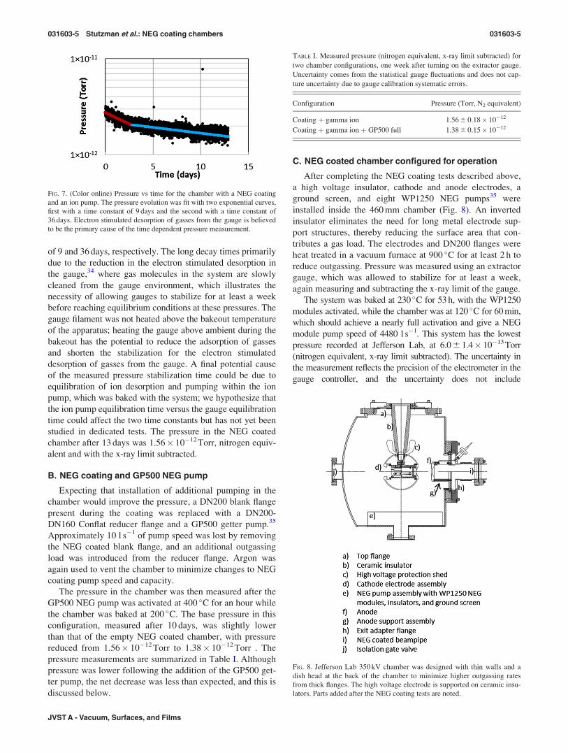
Figure 7 shows the time evolution of the extractor gauge
measured pressure, with the data fitted phenomenologically
using two exponential decay curves yielding time constants
FIG. 4. EDS analysis of the sample in the atomic physics chamber (JILA),
showing an atomic ratio of 2:1:2 for Ti:Zr:V.
FIG. 5. Chamber modifications for pressure measurements. The NEG wires
were removed, and an ion pump, extractor gauge, and rough pump behind a
valve were added. For the second configuration, a GP500 flange mounted
NEG pump was added.
FIG. 6. (Color online) X-ray limit measurement example for an extractor
gauge. The repeller voltage is varied, and over a threshold of 320 V, no gas
phase ions can reach the collector. The remaining current is due to photo-
emission of electrons from x-rays in the gauge and is subtracted as a signifi-
cant source of background at these pressures. In this measurement, the x-ray
limit is 1.1� 10�12 Torr.
031603-4 Stutzman et al.: NEG coating chambers 031603-4
J. Vac. Sci. Technol. A, Vol. 36, No. 3, May/Jun 2018
of 9 and 36 days, respectively. The long decay times primarily
due to the reduction in the electron stimulated desorption in
the gauge,34 where gas molecules in the system are slowly
cleaned from the gauge environment, which illustrates the
necessity of allowing gauges to stabilize for at least a week
before reaching equilibrium conditions at these pressures. The
gauge filament was not heated above the bakeout temperature
of the apparatus; heating the gauge above ambient during the
bakeout has the potential to reduce the adsorption of gasses
and shorten the stabilization for the electron stimulated
desorption of gasses from the gauge. A final potential cause
of the measured pressure stabilization time could be due to
equilibration of ion desorption and pumping within the ion
pump, which was baked with the system; we hypothesize that
the ion pump equilibration time versus the gauge equilibration
time could affect the two time constants but has not yet been
studied in dedicated tests. The pressure in the NEG coated
chamber after 13 days was 1.56� 10�12Torr, nitrogen equiv-
alent and with the x-ray limit subtracted.
B. NEG coating and GP500 NEG pump
Expecting that installation of additional pumping in the
chamber would improve the pressure, a DN200 blank flange
present during the coating was replaced with a DN200-
DN160 Conflat reducer flange and a GP500 getter pump.35
Approximately 10 l s�1 of pump speed was lost by removing
the NEG coated blank flange, and an additional outgassing
load was introduced from the reducer flange. Argon was
again used to vent the chamber to minimize changes to NEG
coating pump speed and capacity.
The pressure in the chamber was then measured after the
GP500 NEG pump was activated at 400 �C for an hour while
the chamber was baked at 200 �C. The base pressure in this
configuration, measured after 10 days, was slightly lower
than that of the empty NEG coated chamber, with pressure
reduced from 1.56� 10�12 Torr to 1.38� 10�12 Torr . The
pressure measurements are summarized in Table I. Although
pressure was lower following the addition of the GP500 get-
ter pump, the net decrease was less than expected, and this is
discussed below.
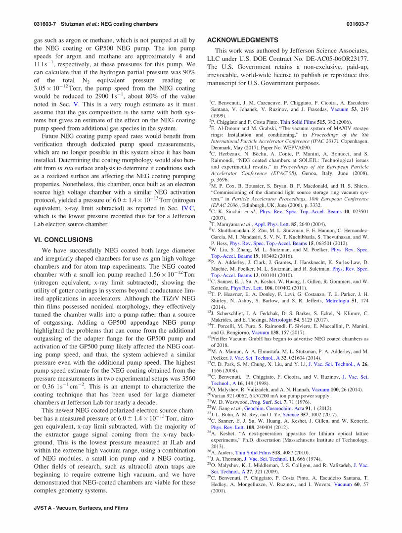
C. NEG coated chamber configured for operation
After completing the NEG coating tests described above,
a high voltage insulator, cathode and anode electrodes, a
ground screen, and eight WP1250 NEG pumps35 were
installed inside the 460 mm chamber (Fig. 8). An inverted
insulator eliminates the need for long metal electrode sup-
port structures, thereby reducing the surface area that con-
tributes a gas load. The electrodes and DN200 flanges were
heat treated in a vacuum furnace at 900 �C for at least 2 h to
reduce outgassing. Pressure was measured using an extractor
gauge, which was allowed to stabilize for at least a week,
again measuring and subtracting the x-ray limit of the gauge.
The system was baked at 230 �C for 53 h, with the WP1250
modules activated, while the chamber was at 120 �C for 60 min,
which should achieve a nearly full activation and give a NEG
module pump speed of 4480 l s�1. This system has the lowest
pressure recorded at Jefferson Lab, at 6.0 6 1.4� 10�13Torr
(nitrogen equivalent, x-ray limit subtracted). The uncertainty in
the measurement reflects the precision of the electrometer in the
gauge controller, and the uncertainty does not include
TABLE I. Measured pressure (nitrogen equivalent, x-ray limit subtracted) for
two chamber configurations, one week after turning on the extractor gauge.
Uncertainty comes from the statistical gauge fluctuations and does not cap-
ture uncertainty due to gauge calibration systematic errors.
Configuration Pressure (Torr, N2 equivalent)
Coating þ gamma ion 1.56 6 0.18� 10�12
Coating þ gamma ion þ GP500 full 1.38 6 0.15� 10�12
FIG. 8. Jefferson Lab 350 kV chamber was designed with thin walls and a
dish head at the back of the chamber to minimize higher outgassing rates
from thick flanges. The high voltage electrode is supported on ceramic insu-
lators. Parts added after the NEG coating tests are noted.
FIG. 7. (Color online) Pressure vs time for the chamber with a NEG coating
and an ion pump. The pressure evolution was fit with two exponential curves,
first with a time constant of 9 days and the second with a time constant of
36 days. Electron stimulated desorption of gasses from the gauge is believed
to be the primary cause of the time dependent pressure measurement.
031603-5 Stutzman et al.: NEG coating chambers 031603-5
JVST A - Vacuum, Surfaces, and Films
contributions due to the calibration coefficient uncertainty for
the gauge. We can compare the base pressure in the NEG
coated chamber with that in another JLab high voltage chamber
that was identical in construction and processing but not NEG
coated. The pressure in this uncoated chamber, installed for use
on an less pressure sensitive, unpolarized electron source,
achieved a value of 2.3� 10�11Torr, a factor of 40 worse than
the NEG coated chamber.
V. NEG COATING PUMP SPEED ESTIMATION
Since the NEG coated chamber was put into use for an
electron gun, dedicated pump speed tests were not performed
on the NEG coating. However, using the pressure measure-
ment from two pumping configurations, we can solve Eq. (1)
to estimate the coating pump speed and chamber outgassing
for the NEG coated chamber,
S ¼ q
P; (1)
where S is the pump speed (l s�1), q is the total chamber out-
gassing load (Torr l s�1), and P is the measured pressure
(Torr). This requires three main assumptions: the first being
that the ion pump speed for the system can be extrapolated
linearly from the manufacturer lowest measured pressure to
our operating pressure, supported by our measurements of a
linear relationship between ion pump current and an extrac-
tor gauge through this pressure range. The second assump-
tion that must be made is that the predominant gas in
the system is hydrogen. The estimated uncertainty in the cal-
culated chamber outgassing and coating pump speed from
this assumption will be discussed. We also use the manufac-
turer’s data that the ion pump speed for hydrogen is a factor
of 1.88 compared to that for nitrogen.36 The final assump-
tion, which may present the largest source of uncertainty, is
that the pump speed of the NEG coating in the two chamber
configurations is the same. The effect of this assumption will
be further discussed in Sec. V A.
The pressures recorded in Table I for the two system con-
figurations must be converted from nitrogen equivalent pres-
sures to hydrogen partial pressures, multiplying by a factor
of 2.17 for the extractor gauge sensitivity difference between
the two gasses (Table II).
For the NEG coated chamber with only an ion pump, the
black line in Fig. 9 shows a set of solutions to Eq. (2); any
combination of NEG coating pump speed and outgassing
rate from the chamber will satisfy
P ¼ q1
SIP þ SNC; (2)
where q1 is the outgassing load for the chamber, SNC is the
pump speed for the NEG coating, and SIP is 14 l s�1 for
hydrogen at 10�12 Torr (extrapolated linearly from published
data).
We can then further constrain the solution to this problem
by including the pressure measured with the GP500 append-
age NEG pump. For this case, we have
P ¼ q1 þ q2
SIP þ SNC þ SGP; (3)
where q1 is again the outgassing of the chamber that is
unchanged from the first case, q2 is the additional outgassing
from the reducer flange, and SGP is the additional 1200 l s�1
pump speed from the GP500 pump. To estimate q2, we know
the surface area and that the outgassing rate for the untreated
flange is likely in the range of 3–7� 10�12 Torr l s�1 cm�2.
The pink band indicates the range of possible outgassing for
the flange and adds uncertainty to our intersection of the two
lines and the solution to the outgassing and pump speed of
the system.
The intersection of the lines in Fig. 9 gives a NEG coat-
ing pump speed of 3560 l�1 6 300 l s�1 or 0.35 l s�1 cm�2,
with the quoted uncertainty coming from the estimated
uncertainty in the additional gas load from the reducer
flange.
A. Uncertainty estimation
Uncertainty in the pump speed calculation is introduced
from each assumption used in the calculation. Since we do
not precisely know the outgassing rate of the reducer flange
added with the GP500 module, we included uncertainty for
that value as described above. Our assumption that hydrogen
is the dominant gas species gives us an additional source of
uncertainty. The gas composition in the chamber was not
measured but undoubtedly contains methane, CO, and CO2
typically found in UHV systems, as well as argon due to
implantation in the NEG coating during sputtering. To exam-
ine a limiting condition, we can consider the scenario where
10% of the gas in the system is composed of a nongetterable
TABLE II. Nitrogen equivalent pressures are converted to hydrogen partial
pressures using the gauge sensitivity for hydrogen.
Configuration
Pressure
(Torr, N2 equivalent)
Pressure
(Torr, H2)
NEG coating and ion pump 1.56� 10�12 3.38� 10�12
NEG coating, ion pump and GP500 1.38� 10�12 3.00� 10�12
FIG. 9. (Color online) Black line represents the combinations of outgassing
and NEG coating pump speed (S) which satisfy Eq. (2) for the NEG coating
and ion pump system. The red line represents the combinations of q and Swhich satisfy Eq. (3) for the system with the added GP500 appendage NEG
pump. The uncertainty in the outgassing rate of the adapter flange is indi-
cated by the wider pink line. The intersection of these two lines shows val-
ues of q and S which are consistent in both cases.
031603-6 Stutzman et al.: NEG coating chambers 031603-6
J. Vac. Sci. Technol. A, Vol. 36, No. 3, May/Jun 2018
gas such as argon or methane, which is not pumped at all by
the NEG coating or GP500 NEG pump. The ion pump
speeds for argon and methane are approximately 4 and
11 l s�1, respectively, at these pressures for this pump. We
can calculate that if the hydrogen partial pressure was 90%
of the total N2 equivalent pressure reading or
3.05� 10�12 Torr, the pump speed from the NEG coating
would be reduced to 2900 l s�1, about 80% of the value
noted in Sec. V. This is a very rough estimate as it must
assume that the gas composition is the same with both sys-
tems but gives an estimate of the effect on the NEG coating
pump speed from additional gas species in the system.
Future NEG coating pump speed rates would benefit from
verification through dedicated pump speed measurements,
which are no longer possible in this system since it has been
installed. Determining the coating morphology would also ben-
efit from in situ surface analysis to determine if conditions such
as a oxidized surface are affecting the NEG coating pumping
properties. Nonetheless, this chamber, once built as an electron
source high voltage chamber with a similar NEG activation
protocol, yielded a pressure of 6.0 6 1.4� 10�13Torr (nitrogen
equivalent, x-ray limit subtracted) as reported in Sec. IV C,
which is the lowest pressure recorded thus far for a Jefferson
Lab electron source chamber.
VI. CONCLUSIONS
We have successfully NEG coated both large diameter
and irregularly shaped chambers for use as gun high voltage
chambers and for atom trap experiments. The NEG coated
chamber with a small ion pump reached 1.56� 10�12 Torr
(nitrogen equivalent, x-ray limit subtracted), showing the
utility of getter coatings in systems beyond conductance lim-
ited applications in accelerators. Although the TiZrV NEG
thin films possessed nonideal morphology, they effectively
turned the chamber walls into a pump rather than a source
of outgassing. Adding a GP500 appendage NEG pump
highlighted the problems that can come from the additional
outgassing of the adapter flange for the GP500 pump and
activation of the GP500 pump likely affected the NEG coat-
ing pump speed, and thus, the system achieved a similar
pressure even with the additional pump speed. The highest
pump speed estimate for the NEG coating obtained from the
pressure measurements in two experimental setups was 3560
or 0.36 l s�1 cm�2. This is an attempt to characterize the
coating technique that has been used for large diameter
chambers at Jefferson Lab for nearly a decade.
This newest NEG coated polarized electron source cham-
ber has a measured pressure of 6.0 6 1.4� 10�13 Torr, nitro-
gen equivalent, x-ray limit subtracted, with the majority of
the extractor gauge signal coming from the x-ray back-
ground. This is the lowest pressure measured at JLab and
within the extreme high vacuum range, using a combination
of NEG modules, a small ion pump and a NEG coating.
Other fields of research, such as ultracold atom traps are
beginning to require extreme high vacuum, and we have
demonstrated that NEG-coated chambers are viable for these
complex geometry systems.
ACKNOWLEDGMENTS
This work was authored by Jefferson Science Associates,
LLC under U.S. DOE Contract No. DE-AC05-06OR23177.
The U.S. Government retains a non-exclusive, paid-up,
irrevocable, world-wide license to publish or reproduce this
manuscript for U.S. Government purposes.
1C. Benvenuti, J. M. Cazeneuve, P. Chiggiato, F. Cicoira, A. Escudeiro
Santana, V. Johanek, V. Ruzinov, and J. Fraxedas, Vacuum 53, 219
(1999).2P. Chiggiato and P. Costa Pinto, Thin Solid Films 515, 382 (2006).3E. Al-Dmour and M. Grabski, “The vacuum system of MAXIV storage
rings: Installation and conditioning,” in Proceedings of the 8thInternational Particle Accelerator Conference (IPAC 2017), Copenhagen,
Denmark, May (2017), Paper No. WEPVA090.4C. Herbeaux, N. Bechu, A. Conte, P. Manini, A. Bonucci, and S.
Raimondi, “NEG coated chambers at SOLEIL: Technological issues
and experimental results,” in Proceedings of the European ParticleAccelerator Conference (EPAC’08), Genoa, Italy, June (2008),
p. 3696.5M. P. Cox, B. Boussier, S. Bryan, B. F. Macdonald, and H. S. Shiers,
“Commissioning of the diamond light source storage ring vacuum sys-
tem,” in Particle Accelerator Proceedings, 10th European Conference(EPAC 2006), Edinburgh, UK, June (2006), p. 3332.
6C. K. Sinclair et al., Phys. Rev. Spec. Top.-Accel. Beams 10, 023501
(2007).7T. Maruyama et al., Appl. Phys. Lett. 85, 2640 (2004).8V. Shutthanandan, Z. Zhu, M. L. Stutzman, F. E. Hannon, C. Hernandez-
Garcia, M. I. Nandasiri, S. V. N. T. Kuchibhatla, S. Thevuthasan, and W.
P. Hess, Phys. Rev. Spec. Top.-Accel. Beams 15, 063501 (2012).9W. Liu, S. Zhang, M. L. Stutzman, and M. Poelker, Phys. Rev. Spec.
Top.-Accel. Beams 19, 103402 (2016).10P. A. Adderley, J. Clark, J. Grames, J. Hansknecht, K. Surles-Law, D.
Machie, M. Poelker, M. L. Stutzman, and R. Suleiman, Phys. Rev. Spec.
Top.-Accel. Beams 13, 010101 (2010).11C. Sanner, E. J. Su, A. Keshet, W. Huang, J. Gillen, R. Gommers, and W.
Ketterle, Phys Rev. Lett. 106, 010402 (2011).12T. P. Heavner, E. A. Donley, F. Levi, G. Costanzo, T. E. Parker, J. H.
Shirley, N. Ashby, S. Barlow, and S. R. Jefferts, Metrologia 51, 174
(2014).13J. Scherschligt, J. A. Fedchak, D. S. Barker, S. Eckel, N. Klimov, C.
Makrides, and E. Tiesinga, Metrologia 54, S125 (2017).14T. Porcelli, M. Puro, S. Raimondi, F. Siviero, E. Maccallini, P. Manini,
and G. Bongiorno, Vacuum 138, 157 (2017).15Pfeiffer Vacuum GmbH has begun to advertise NEG coated chambers as
of 2018.16M. A. Mamun, A. A. Elmustafa, M. L. Stutzman, P. A. Adderley, and M.
Poelker, J. Vac. Sci. Technol., A 32, 021604 (2014).17C. D. Park, S. M. Chung, X. Liu, and Y. Li, J. Vac. Sci. Technol., A 26,
1166 (2008).18C. Benvenuti, P. Chiggiato, F. Cicoira, and V. Ruzinov, J. Vac. Sci.
Technol., A 16, 148 (1998).19O. Malyshev, R. Valizadeh, and A. N. Hannah, Vacuum 100, 26 (2014).20Varian 921-0062, 6 kV/200 mA ion pump power supply.21W. D. Westwood, Prog. Surf. Sci. 7, 71 (1976).22W. Jiang et al., Geochim. Cosmochim. Acta 91, 1 (2012).23J. L. Bohn, A. M. Rey, and J. Ye, Science 357, 1002 (2017).24C. Sanner, E. J. Su, W. Huang, A. Keshet, J. Gillen, and W. Ketterle,
Phys. Rev. Lett. 108, 240404 (2012).25A. Keshet, “A next-generation apparatus for lithium optical lattice
experiments,” Ph.D. dissertation (Massachusetts Institute of Technology,
2013).26A. Anders, Thin Solid Films 518, 4087 (2010).27J. A. Thornton, J. Vac. Sci. Technol. 11, 666 (1974).28O. Malyshev, K. J. Middleman, J. S. Colligon, and R. Valizadeh, J. Vac.
Sci. Technol., A 27, 321 (2009).29C. Benvenuti, P. Chiggiato, P. Costa Pinto, A. Escudeiro Santana, T.
Hedley, A. Mongelluzzo, V. Ruzinov, and I. Wevers, Vacuum 60, 57
(2001).
031603-7 Stutzman et al.: NEG coating chambers 031603-7