Page 1
CODES AND STANDARDS ENHANCEMENT INITIATIVE (CASE)
Nonresidential Lighting Controls:
Clarification and Control Credits Measure Number: 2016-NR-LTG-5-F
Nonresidential Indoor Lighting Controls
2016 CALIFORNIA BUILDING ENERGY EFFICIENCY STANDARDS
California Utilities Statewide Codes and Standards Team October 2014
This report was prepared by the California Statewide Codes and Standards Enhancement (CASE) Program that is funded, in part, by California
utility customers under the auspices of the California Public Utilities Commission.
Copyright 2014 Pacific Gas and Electric Company, Southern California Edison, Southern California Gas Company, San Diego Gas & Electric
Company, Los Angeles Department of Water and Power.
All rights reserved, except that this document may be used, copied, and distributed without modification.
Neither PG&E, SCE, SDG&E, SoCalGas, LADWP nor any of its employees makes any warranty, express of implied; or assumes any legal
liability or responsibility for the accuracy, completeness or usefulness of any data, information, method, product, policy or process disclosed
in this document; or represents that its use will not infringe any privately-owned rights including, but not limited to, patents, trademarks or
copyrights.
Page 2
2016 Title 24 CASE Report – NR Lighting Controls: Clarification and Control Credits Page i
TABLE OF CONTENTS
1. Introduction ............................................................................................... 1
2. Measure Description ................................................................................. 2
2.1 Measure Overview ....................................................................................................... 2
2.1.1 Measure Description ...................................................................................................... 2
2.1.2 Measure History and Existing Standards ....................................................................... 6
2.1.3 Alignment with Zero Net Energy Goals ...................................................................... 10
2.1.4 Relationship to Other Title 24 Measures ..................................................................... 10
2.2 Summary of Changes to Code Documents .............................................................. 11
2.2.1 Catalogue of Proposed Changes .................................................................................. 11
2.2.2 Standards Change Summary ........................................................................................ 13
2.2.3 Standards Reference Appendices Change Summary ................................................... 14
2.2.4 Nonresidential Alternative Calculation Method (ACM) Reference Manual Change
Summary ...................................................................................................................... 20
2.2.5 Compliance Forms Change Summary ......................................................................... 21
2.2.6 Simulation Engine Adaptations ................................................................................... 21
2.2.7 Other Areas Affected ................................................................................................... 21
2.3 Code Implementation ................................................................................................ 21
2.3.1 Verifying Code Compliance ........................................................................................ 21
2.3.2 Code Implementation ................................................................................................... 22
2.3.3 Acceptance Testing ...................................................................................................... 22
2.4 Issues Addressed During IOU CASE Development Process .................................. 23
3. Market Analysis .......................................................................................23
3.1 Market Structure ....................................................................................................... 23
3.2 Market Availability and Current Practices ............................................................. 24
3.3 Useful Life, Persistence, and Maintenance .............................................................. 24
3.4 Market Impacts and Economic Assessments ........................................................... 24
3.4.1 Impact on Contractors .................................................................................................. 24
3.4.2 Impact on Building Designers ...................................................................................... 24
3.4.3 Impact on Occupational Safety and Health .................................................................. 25
3.4.4 Impact on Building Owners and Occupants................................................................. 25
3.4.5 Impact on Energy Consultants ..................................................................................... 25
Page 3
2016 Title 24 CASE Report – NR Lighting Controls: Clarification and Control Credits Page ii
3.4.6 Impact on Building Inspectors ..................................................................................... 25
3.4.7 Impact on Statewide Employment ............................................................................... 25
3.5 Economic Impacts ...................................................................................................... 26
3.5.1 Creation or Elimination of Jobs ................................................................................... 26
3.5.2 Creation or Elimination of Businesses within California ............................................ 26
3.5.3 Competitive Advantages or Disadvantages for Businesses within California ............. 27
3.5.4 Increase or Decrease of Investments in the State of California ................................... 27
3.5.5 Incentives for Innovation in Products, Materials, or Processes ................................... 27
3.5.6 Effects on the State General Fund, State Special Funds and Local Governments ....... 27
3.5.7 Impacts on Specific Persons......................................................................................... 28
4. Proposed Language .................................................................................29
4.1 Standards .................................................................................................................... 29
4.2 Reference Appendices ................................................................................................ 35
Nonresidential Appendix NA7 ................................................................................................. 42
4.3 ACM Reference Manual ............................................................................................ 43
4.4 Compliance Manuals and Forms .............................................................................. 47
5. References .................................................................................................48
Appendix A Sample Fourier Filtering Command language for MATLAB .....50
Page 4
2016 Title 24 CASE Report – NR Lighting Controls: Clarification and Control Credits Page iii
List of Tables
Table 1: Scope of Code Change Proposal...................................................................................... vi
Table 2: Scope of Code Change Proposal..................................................................................... 11
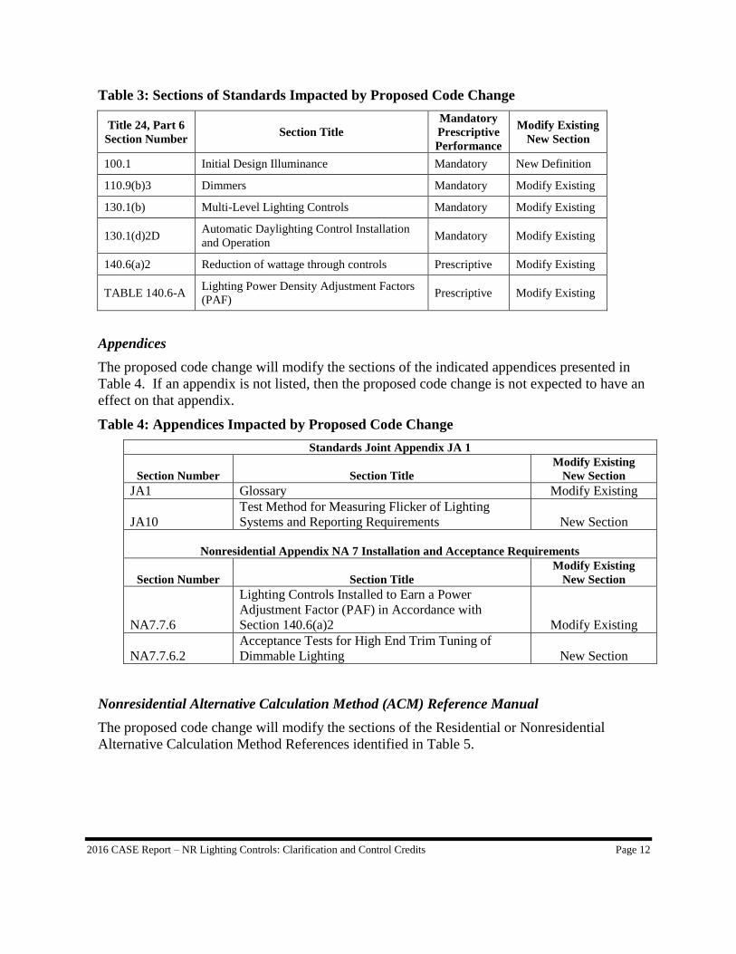
Table 3: Sections of Standards Impacted by Proposed Code Change .......................................... 12
Table 4: Appendices Impacted by Proposed Code Change .......................................................... 12
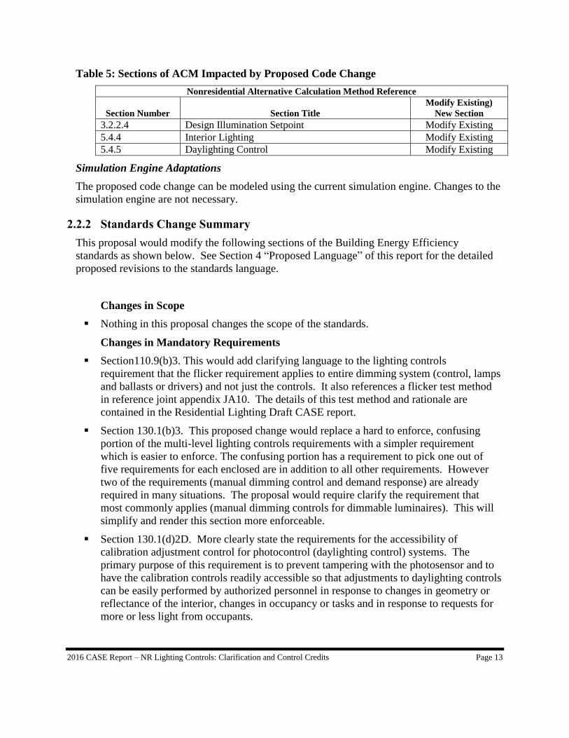
Table 5: Sections of ACM Impacted by Proposed Code Change ................................................. 13
Table 6: Comparison of unfiltered percent flicker results between two test labs ......................... 19
List of Figures
Figure 1: Photocontrol Sensor Location in Skylight Well .............................................................. 3
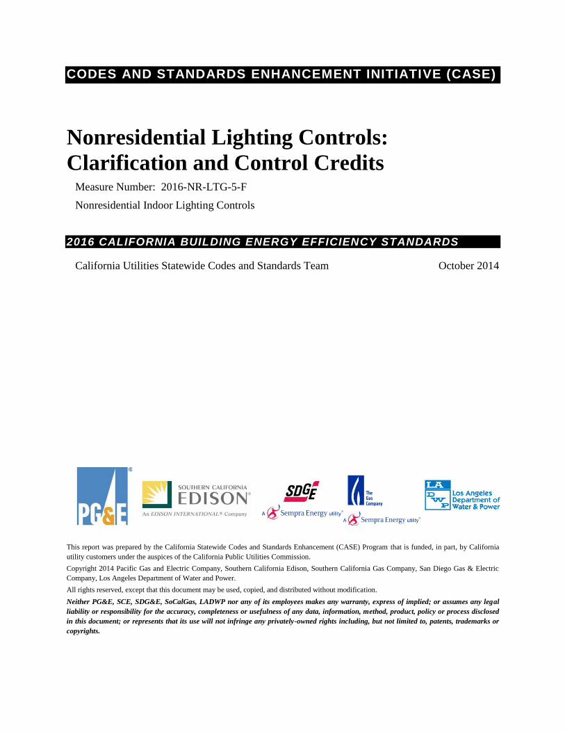
Figure 2: Meta-Study of Lighting Control Savings [LBNL 2012] ................................................. 4
Figure 3: Dimming and Dimming plus OFF control (Fig 10 in NR ACM) ................................... 5
Figure 4: ASHRAE 90.1 Daylighting Controls Comparison.......................................................... 8
Figure 5: Detection and Acceptability of Stroboscopic Effects (LRC 2012) ............................... 16
Figure 6: Low risk and no observable effect regions for flicker (Lehman et al 2014) overlaid with
region of graph not compliant with "reduced flicker operation" requirement ....................... 17
Figure 7: Filtered Flicker Test Data for 25 LED A-lamps (filtered flicker proposed for CA
standards) ............................................................................................................................... 18
Figure 8: Unfiltered Flicker Test Data for 25 LED A-Lamps (unfiltered flicker not proposed for
CA standards) ......................................................................................................................... 19
Page 5
2016 Title 24 CASE Report – NR Lighting Controls: Clarification and Control Credits Page iv
Document Information
Category: Codes and Standards
Keywords: Statewide CASE, Statewide Codes and Standards Team, Statewide C&S Team,
Codes and Standards Enhancements, Title 24, 2016, efficiency, nonresidential lighting
controls, daylighting controls, dimming plus off control, high end trim, tuning, Power
Adjustment Factor.
Page 6
2016 Title 24 CASE Report – NR Lighting Controls: Clarification and Control Credits Page v
EXECUTIVE SUMMARY
Introduction
The Codes and Standards Enhancement (CASE) initiative presents recommendations to
support California Energy Commission’s (CEC) efforts to update California’s Building Energy
Efficiency Standards (Title 24) to include new requirements or to upgrade existing
requirements for various technologies. The four California Investor Owned Utilities (IOUs) –
Pacific Gas and Electric Company, San Diego Gas and Electric, Southern California Edison
and Southern California Gas Company – and Los Angeles Department of Water and Power
(LADWP) sponsored this effort. The program goal is to prepare and submit proposals that will
result in cost-effective enhancements to energy efficiency in buildings. This report and the
code change proposal presented herein is a part of the effort to develop technical and cost-
effectiveness information for proposed regulations on building energy efficient design
practices and technologies.
The overall goal of this CASE Report is to propose a code change proposal for measure name.
The report contains pertinent information that justifies the code change including:
Description of the code change proposal, the measure history, and existing standards
(Section 2);
Market analysis, including a description of the market structure for specific technologies,
market availability, and how the proposed standard will impact building owners and
occupants, builders, and equipment manufacturers, distributers, and sellers (Section 3);
Proposed code change language (Section 4).
Scope of Code Change Proposal
This Lighting Controls Requirement Clarifications and Lighting Control Credits proposal will
affect the code documents listed in Table 1. As a clean-up proposal, it broadly impacts the
various portions of the standards that address controls. Thus the definitions in Section 100.1
are affected as are the mandatory requirements for lighting controls in Section 110.9 and the
mandatory controls that must be installed in Section 130.1 and the Power Adjustment Factors
(PAFs) in Section 140.6. One of these controls receiving a Power Adjustment Factor must
pass an acceptance test to receive the lighting credit and thus a new acceptance test is added to
Reference Nonresidential Appendix NA7.6.4. The power adjustment factor also impact the
deemed savings associated with high end trim tuning of dimming systems and this carries over
into the t performance approach and thus affects the Nonresidential Alternative Compliance
Method (ACM) Reference Manual.
Page 7
2016 Title 24 CASE Report – NR Lighting Controls: Clarification and Control Credits Page vi
Table 1: Scope of Code Change Proposal
Standards
Requirements
(see note below)
Appendix Modeling
Algorithms Forms
100.1
110.9(b)3 [M]
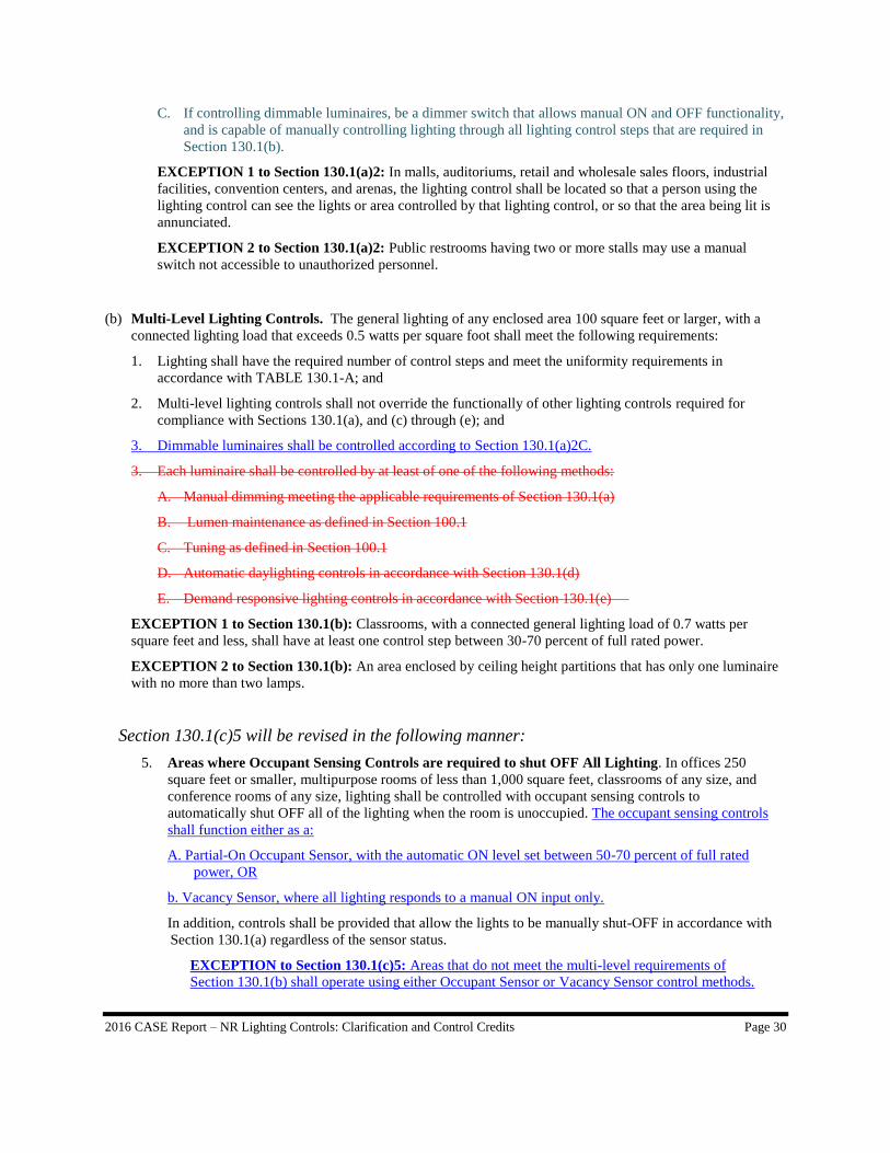
130.1(b)3 [M]
130.1(d)2D [M]
140.6(a)2H [CC]
140.6(a)2J [CC]
Table 140.6-A [Ps]
NA7.6.4 [CC] NACM 3.2.2.2 [Pm]
NACM 3.2.2.4 [Pm]
NACM 5.4.4 [Pm]
NACM 5.4.5 [Pm]
NRCC-LTI-02-E
NRCA-LTI-03-A
NRCA-LTI-04-A (new)
Note: An (M) indicates mandatory requirements, (Ps) Prescriptive, (CC) Control Credit, (Pm) Performance.
Measure Description
This CASE report provides the rationale for the adoption of the following changes to the
California building efficiency standards which simplifies, clarifies and provides compliance
credit for inexpensive and effective control strategies.
Section 100.1 A definition of “initial design illuminance” is added to support the
required activities to qualify for a Power Adjustment Factor for “High End Trim
Tuning of Dimmable Lighting in Section 140.6(a)2H (see below).
Section110.9(b)3. This would add clarifying language to the lighting controls
requirement that the flicker requirement applies to entire dimming system (control,
lamps and ballasts or drivers) and not just the controls. It also references a flicker test
method in reference Joint Appendix JA10. The details of this test method and rationale
were also contained in the Residential Lighting CASE report. It is repeated here for
completeness
Section 130.1(b)3. This proposed change would replace a hard to enforce, confusing
portion of the multi-level lighting controls requirements with a simpler requirement
which is easier to enforce. The confusing portion has a requirement to pick one out of
five requirements for each enclosed area in addition to all other requirements. However
two of the requirements (manual dimming control and demand response) are already
required in many situations. The proposal would require clarify the requirement that
most commonly applies (manual dimming controls for dimmable luminaires). This will
simplify and render this section more enforceable.
Section 130.1(d)2D. More clearly state the requirements for the accessibility of
calibration adjustment control for photocontrol (daylighting control) systems. The
primary purpose of this requirement is to prevent tampering with the photosensor and
to have the calibration controls readily accessible so that adjustments to daylighting
controls can be easily performed by authorized personnel in response to changes in
geometry or reflectance of the interior, changes in occupancy or tasks and in response
to requests for more or less light from occupants.
Section 140.6(a)2H. Remove the PAF for Partial-ON Dimming Controls (now a
mandatory requirement) and replace with a description of the requirements of the
Daylight Dimming Plus OFF controls. It should be noted that ASHRAE 90.1-2013
contains a mandatory requirement for daylighting controls that turn lights all the way
Page 8
2016 Title 24 CASE Report – NR Lighting Controls: Clarification and Control Credits Page vii
OFF when the space is fully daylit. This proposal is a halfway step towards having
daylighting control requirements as stringent as found in ASHRAE 90.1. Ideally this
PAF prepares the market for this control strategy being the default or mandatorily
required in the 2019 Title 24 standards.
Section 140.6(a)2J. Replace the description of Manual Dimming or Multiscene
Programmable Dimming System controls that qualify for a PAF with the description of
Manual Dimming Controls with High end Trim Tuning controls that qualify for a PAF.
This section also notes that the initial design illuminance must be on the construction
documents and that high end trim must be tuned so that it is within 10% of the initial
design illuminance as verified by the acceptance tests as contained in nonresidential
appendix NA7.6.4.
Table 140.6-A Remove two Power Adjustment Factors in Table 140.6-A for Partial-On
controls and dimming system controls. The rationale for removing these PAFs is
contained in the Nonresidential Lighting Controls Partial-ON Occupancy Sensors
CASE report. These changes are included in the proposed changed code in this report
for ease of understanding how the proposed changes from both CASE reports would
impact this table and this section
Table 140.6-A Add two Power Adjustment Factors in Table 140.6-A for daylight
dimming plus OFF control and tuning of dimming systems.
NA7.7.6.2 “Acceptance Tests for High End Trim Tuning of Dimmable Lighting.” This
new acceptance test is added to verify that lighting systems claiming the High End
Trim Tuning Power Adjustment factor have tuned the lighting system appropriately.
JA10 Test Method for Measuring Flicker of Lighting Systems and Reporting
Requirements. This test method quantifies the long standing requirement of “low
flicker operation for dimming systems. See also the clarification of dimming
requirement in Section110.9(b)3.
This proposal interacts with and builds upon the Residential Lighting and the Nonresidential
Lighting Controls Partial-ON Occupancy Sensors CASE reports. The full citations for the
Residential Lighting and the Nonresidential Lighting Controls Partial-ON Occupancy Sensors
CASE reports can be found in the References Section of this report.
Section 2 of this report provides detailed information about the code change proposal
including: Section 2.2 Summary of Changes to Code Documents (page 11) provides a
section-by-section description of the proposed changes to the standards, appendices, alternative
compliance manual and other documents that will be modified by the proposed code change.
See the following tables for an inventory of sections of each document that will be modified:
Table 2: Scope of Code Change Proposal (page 11)
Table 3: Sections of Standards Impacted by Proposed Code Change (page 12)
Table 4: Appendices Impacted by Proposed Code Change (page 12)
Table 5: Sections of ACM Impacted by Proposed Code Change (page 13)
Detailed proposed changes to the text of the building efficiency standards, the reference
appendices, and are given in Section 4 Proposed Language of this report. This section
proposes modifications to language with additions identified with underlined text and deletions
identified with struck out text.
Page 9
2016 Title 24 CASE Report – NR Lighting Controls: Clarification and Control Credits Page viii
The following documents will be modified by the proposed change:
Main text of Title 24, part 6
Nonresidential Standards Appendix NA7 (acceptance tests)
Nonresidential Alternative Compliance Method (NACM) Manual.
Market Analysis and Regulatory Impact Assessment
The code simplification aspects of this proposal are cost effective as they reduce compliance
cost without loss in energy savings. The lighting controls Power Adjustment Factors (PAFs)
provide credit for lighting controls that save significant amounts of energy for little cost.
However as PAFs, we are not calculating cost-effectiveness as these requirements do not
increase the stringency of the standards but rather provide code incentives for use of
technologies that may be required in future version of the standards. Over the long term this
proposal increases the wealth of the State of California. California consumers and businesses
save more money on energy than they do for financing the efficiency measure. As a result this
leaves more money available for discretionary and investment purposes.
The expected impacts of the proposed code change on various stakeholders are summarized
below:
Impact on contractors: Simpler code will render it easier to comply. Added control
credits will allow more equipment to be installed (both luminaires and controls) which
increases bill able work for contractors. The tuning proposal increases the amount of
labor on a job and generates work lighting acceptance test professionals.
Impact on building designers: Simpler code will render it easier to comply. Added
PAFs provide more design flexibility to comply with code. Some lighting designers may
be concerned about increased liability associated with placing design light levels on
design documents even though this is good design practice.
Impact on occupational safety and health: Most of the proposed code changes are not
expected to have an impact on occupational safety and health. The requirement for
calibration adjustments being readily accessible increase occupational safety as it avoids
the need for climbing up to the ceiling level to make photocontrol adjustments.
Impact on building owners and occupants: Since this measure is cost-effective, the
building owner who pays their energy bills is reducing their energy costs more than their
mortgage costs are for the cost of the measure (i.e. there are experiencing net cost
savings). For building occupants that are paying for their energy bills, since the measure
saves more energy cost on a monthly basis than the measure costs on the mortgage as
experiences by the building owner, the pass-through of added mortgage costs into rents is
less than the energy cost savings experienced by occupants.
Impact on equipment retailers (including manufacturers and distributors): The
Power Adjustments help develop a market for controls that have high end trim and for
dimming plus off photocontrols. This slightly increases overall market activity but
should have a large impact on these two control categories. There is a small cost on
manufacturers to conduct flicker testing on products they sell in California. This cost is
small as the cost is defrayed across all the units they sell in California. The test method
Page 10
2016 Title 24 CASE Report – NR Lighting Controls: Clarification and Control Credits Page ix
is similar to the test method for ENERGY STAR compliance so this test can be
structured to the collect the test data once for both purposes.
Impact on energy consultants: Simpler code will render it easier to document
compliance. Power adjustment factors increase the complexity of documentation but this
a voluntary effort when the owner or designers are looking for more lighting power
allowances or they are trying to fully document how more stringent their design is than
the minimal requirements of the code for LEED or other building efficiency certification.
Impact on building inspectors: As compared to the overall code enforcement effort, this
measure has negligible impact on the effort required to enforce the building codes.
However, the portion of this proposal that simplifies the code will render it easier to
enforce.
Statewide Employment Impacts: as mentioned above on the impact on contractors,
when the PAFs are used they generate more work for contractors. High end tuning
requires more labor as it requires that each space taking the credit have the high end trim
tuned to the design light levels defined for that space. In addition this tuning effort must
be verified by an acceptance testing professional, which generates even more work.
Impacts on the creation or elimination of businesses in California: The Lighting
Power Adjustment Factors have had a long history of creating the conditions for
innovative companies to open up shop in California. The occupancy sensor and
daylighting control PAF’s in the 1992 Title 24 standards help generate a market for these
control types. Thus it is not surprising that a number of controls manufacturers were
headquartered in California. More recently the requirement for multi-level controls
created a market for these types of controls.
Impacts on the potential advantages or disadvantages to California businesses: The
Title 24 energy efficiency standards have for years led the rest of the country and the rest
of the world. Many requirements in Title 24 have been adopted by the ASHRAE 90.1
and IECC energy codes in the United States and other codes overseas. Both high end
trim and daylight dimming plus off have been used voluntarily by advanced design teams
and by companies with large real estate holdings. Manufacturers and designers in
California have a leg up on their competitors by having products and service that
incorporate reliable energy savings techniques.
Impacts on the potential increase or decrease of investments in California: The
lighting controls business has become increasingly globalized so that it is hard to predict
just what fraction of increased lighting control investments will be invested in California
but it overall direction is positive in terms of more investment in California lighting
firms.
Impacts on incentives for innovations in products, materials or processes: Since
proposed controls credits are performance based, this allows for equipment suppliers to
develop new technologies that meet the requirements more effectively, more
inexpensively and potentially providing additional amenity in conjunction with the new
functionality.
Impacts on the State General Fund, Special Funds and local government: To the
extent that the Power Adjustment Factors allow designers to install lighting power with
Page 11
2016 Title 24 CASE Report – NR Lighting Controls: Clarification and Control Credits Page x
more equipment (luminaires and controls) costs, there would be slightly more sales tax
and property tax collected. However this is negligible in the context of overall new
construction project costs.
Cost of enforcement to State Government and local governments: The clarification
and simplification components of this proposal reduce the cost of code enforcement for
local jurisdictions. This impact is small.
Impacts on migrant workers; persons by age group, race, or religion: This proposal
and all measures adopted by CEC into Title 24, part 6 do not advantage or discriminate in
regards to race, religion or age group.
Impact on Renters: This proposal is advantageous to renters as it reduces the cost of
utilities which are typically paid by renters. Since the measure saves more energy cost on
a monthly basis than the measure costs on the mortgage as experiences by the landlord,
the pass-through of added mortgage costs into rents is less than the energy cost savings
experienced by renters.
Impact on Commuters: This proposal and all measures adopted by CEC into Title 24,
part 6 are not expected to have an impact on commuters
Statewide Energy Impacts
Power adjustment factors (PAFs) are voluntary and their impact depends upon how frequently
they are used. The primary impact of the PAFs depend upon how frequently they are used and
actual reduction of lighting usage as compared to the reduction embedded in the PAF. The PAFs
for tuning of dimming lighting and dimming plus OFF daylighting controls create credit for these
controls and provide a code incentive for these controls. If these incentives are used, this gives
practitioners and other lighting market participants experience with these controls. The
statewide impacts are long term with the main benefit to the state resulting from market
acceptance of these controls and ultimately adoption of these control strategies as mandatory
measures in future versions of Title 24.
The PAFs have been available in the Title 24 standards since the 1992 version of the code.
These PAFs have been effective in helping develop the market for other lighting controls that
were later on required by the standards including: occupancy sensors, bi-level occupancy sensors
and daylighting controls. These control types are no longer given PAF credit as these controls
are a mandatory requirement in Section 130.1 of the standards.
Cost-effectiveness
Cost-effectiveness is not calculated for this set of measures as what is being proposed is clean-
up language to various sections and a lighting control credit. Thus the stringency of the
standard is not being increased by this proposal and does not require a cost-effectiveness
calculation. However it should be noted that the cost-effectiveness of high end trim tuning of
controllable lighting was found to the be cost-effective in all space types besides classrooms in
the Requirements for Controllable Lighting CASE Study that supported the development of the
Page 12
2016 Title 24 CASE Report – NR Lighting Controls: Clarification and Control Credits Page xi
2013 Title 24 standards. [CASE 2011] Similarly the ASHRAE 90.1 lighting subcommittee
evaluated the costs and savings associated with multi-level plus OFF daylighting controls
before adopting this control strategy into ASHRAE 90.1-2010.1 The Pacific Northwest
National Laboratory conducted an evaluation of savings from multi-level plus OFF controls
which will be briefly discussed later on in this report. [PNNL 2013]
Greenhouse Gas and Water Related Impacts
Greenhouse Gas Impacts
Energy savings are not claimed for these measures and thus there is no claim of Greenhouse
Gas savings
Water Use and Water Quality Impacts
The proposed measure is not expected to have any impacts on water use or water quality,
excluding impacts that occur at power plants.
Acceptance Testing
The high end trim tuning Power Adjustment Factor requires the tuning of light levels to the
initial design illuminance levels tabulated on the construction documents and verified by an
independent third party according to the requirements in the proposed Nonresidential
Appendix NA7.6.4 “Acceptance Tests for High End Trim Tuning of Dimmable Lighting. This
acceptance tests verifies that all lighting systems receiving the credit have their initial design
illuminance listed on the construction documents, these lighting systems are capable of high
end trim control and that the lighting systems is adjusted so that at full light output the light
levels are no greater than 110% of the listed initial design illuminance.
1 ASHRAE 90.1-2013 Section 9.4.1.1(e) “Automatic daylighting controls for sidelighting” and Section 9.4.1.1(f) “Automatic
daylighting controls for toplighting”
Page 13
2016 CASE Report – NR Lighting Controls: Clarification and Control Credits Page 1
1. INTRODUCTION
The Codes and Standards Enhancement (CASE) initiative presents recommendations to
support California Energy Commission’s (CEC) efforts to update California’s Building Energy
Efficiency Standards (Title 24) to include new requirements or to upgrade existing
requirements for various technologies. The four California Investor Owned Utilities (IOUs) –
Pacific Gas and Electric Company, San Diego Gas and Electric, Southern California Edison
and Southern California Gas Company – and Los Angeles Department of Water and Power
(LADWP) sponsored this effort. The program goal is to prepare and submit proposals that will
result in cost-effective enhancements to energy efficiency in buildings. This report and the
code change proposal presented herein is a part of the effort to develop technical and cost-
effectiveness information for proposed regulations on building energy efficient design
practices and technologies.
The overall goal of this CASE Report is to propose changes to the 206 Title 24 part 6 building
efficiency standards in regards to Lighting Controls Requirement Clarifications and Lighting
Control Credits. The report contains pertinent information that justifies the code change.
Section 2 of this CASE Report provides a description of the measure, how the measure came
about, and how the measure helps achieve the state’s zero net energy (ZNE) goals. This section
presents how the Statewide CASE Team envisions the proposed code change would be
enforced and the expected compliance rates. This section also summarized key issues that the
Statewide CASE Team addressed during the CASE development process, including issues
discussed during IOU-sponsored public stakeholder meetings.
Section 3 presents the market analysis, including a review of the current market structure, a
discussion of product availability, and the useful life and persistence of the proposed measure.
This section offers an overview of how the proposed standard will impact various stakeholders
including builders, building designers, building occupants, equipment retailers (including
manufacturers and distributors), energy consultants, and building inspectors. Finally, this
section presents estimates of how the proposed change will impact statewide employment.
The report concludes with specific recommendations for language for the Standards,
Appendices, Alternate Calculation Manual (ACM) Reference Manual and Compliance Forms.
Page 14
2016 CASE Report – NR Lighting Controls: Clarification and Control Credits Page 2
2. MEASURE DESCRIPTION
2.1 Measure Overview
This nonresidential lighting control proposal to the 2016 Title 24 building efficiency standards
is primarily “clean up” and prepares the market for added control requirements in the 2019
standards. Key features of this proposal is to provide credit for high end trim tuning (the
energy rationale for requiring controllable lighting) and daylight dimming plus OFF (similar to
the mandatory daylighting control requirements in the ASHRAE 90.1-2013 national energy
code baseline) and referencing a test method for “low flicker operation” something required by
Title 24 for years but not before quantified with a repeatable test method.
2.1.1 Measure Description
Initial Design Illuminance Section 100.1. This definition supports the manual dimming with
high end trim tuning PAF. This clarifies that the Initial Design Illuminance value is higher
than the Maintained Design Illuminance which is what most designers think of when they hear
the term “design illuminance.”
Dimming system flicker requirements Section110.9(b)3. This would add clarifying language
to the lighting controls requirement that the flicker requirement applies to entire dimming
system (control, lamps and ballasts or drivers) and not just the controls. It also references a
flicker test method in Reference Joint Appendix JA10.
Multi-level control simplification Section 130.1(b)3. This proposed change would replace a
hard to enforce, confusing portion of the multi-level lighting controls requirements with a
simpler requirement which is easier to enforce. The confusing portion has a requirement to
pick one out of five requirements for each enclosed are in addition to all other requirements.
However two of the requirements (manual dimming control and demand response) are already
required in many situations. The proposal would require clarify the requirement that most
commonly applies (manual dimming controls for dimmable luminaires). This will simplify
and render this section more enforceable.
One of the benefits of mandatory requirements is that they are the same for every building and
thus they are easy to enforce. This simplicity is lost when a mandatory requirement is
structured to be a list of pick one requirement out of a list of five requirements. This format is
more readily applied to voluntary rating systems such as LEED where points are assigned for
picking more and more options. The requirements for multi-level control have so many
control steps for linear fluorescent lighting that the simplest approach is to install continuous
dimming controls. When continuous dimming controls are installed Section 130.1(a) [area
controls], requires that a manual dimmer control the lights though all control steps. A manual
dimmer is one of the five controls required in Section 130.1(b). This proposal would just
clarify that when the lighting is continuous dimming that the area control be a manual dimmer.
In most cases this proposal does not change the stringency of the standard but makes it more
understandable and easier to comply with and enforce.
Page 15
2016 CASE Report – NR Lighting Controls: Clarification and Control Credits Page 3
Daylighting Controls Calibration Accessibility Section 130.1(d)2D.
More clearly state the requirements for the accessibility of calibration adjustment control for
photocontrol (daylighting control) systems. The primary purpose of this requirement is to
prevent tampering with the photosensor and to have the calibration controls readily accessible
so that adjustments to daylighting controls can be easily performed by authorized personnel in
response to changes in geometry or reflectance of the interior, changes in occupancy or tasks
and in response to requests for more or less light from occupants.
Daylight Dimming Plus OFF Controls PAF
Section 140.6(a)2H. Replace the description
of the PAF for Partial-ON Dimming Controls
with a description of the requirements of the
Daylight Dimming Plus OFF controls. It
should be noted that ASHRAE 90.1-2013 has
a mandatory requirement that daylighting
controls turn lights all the way OFF when the
space is fully daylit. This proposal is a
halfway step towards having daylighting
control requirements as stringent as found in
ASHRAE 90.1. Ideally this PAF prepares the
market for this control strategy being the
default or the mandatory daylighting controls
requirement in the 2019 Title 24 standards.
Manual Dimming Controls with High End
Trim Tuning PAF Section 140.6(a)2J. Replace the description of Manual Dimming
or Multiscene Programmable Dimming
System controls that qualify for a PAF with
the description of Manual Dimming Controls
with High end Trim Tuning controls that
qualify for a PAF. This section also notes
that the initial design illuminance must be on
the construction documents and that high end
trim must be tuned so that it is no greater than
110% of the initial design illuminance as
verified by the acceptance tests as contained
in nonresidential appendix NA7.6.4. Add two
Power Adjustment Factors in Table 140.6-A for daylighting dimming plus OFF control and
tuning of dimming systems.
Remove three PAFs and Add two new PAF’s in Table 140.6-A The Power Adjustment
factors (PAFs) for partial-on controls and manual and scene controls for dimming systems and
the combination of manual dimming and partial on control are no longer needed as continuous
dimming is essentially required by the 2013 changes to Section 130.1(b) multi-level controls.
Figure 1: Photocontrol Sensor Location in
Skylight Well
Page 16
2016 CASE Report – NR Lighting Controls: Clarification and Control Credits Page 4
The rationale for removing these PAFs is contained in the Nonresidential Lighting Controls
Partial-ON Occupancy Sensors draft CASE report. These changes are included in the
proposed changed code in this report for ease of understanding how the proposed changes from
both CASE reports would impact Table 140.6-A.
This CASE report describes the
rationale for adding Power
Adjustment Factors for daylight
dimming plus OFF control and
manual dimming controls with
high end trim and tuning. A 10%
PAF is proposed for the daylight
dimming plus OFF control and
10% PAF is proposed for manual
dimming controls with high end
trim and tuning.
The 10% PAF for daylight
dimming plus OFF control
accounts for the typical savings
associated with the addition of an
OFF control to daylight dimming.
Typically dimming fluorescent
ballasts consume around 20% of
full power when they are fully
dimmed. In many applications
under skylights or in the primary sidelit zones, one can turn off lights for about half the day as
these zones are under full daylight conditions about half the day.
The 10% PAF for manual dimming controls with high end trim and tuning is a very
conservative estimate of the savings possible from this control strategy. During the
development of the 2013 Title 24 standards, the CASE [2011] report for “Requirements for
Controllable Lighting” estimated that for all lighting “tuning lighting to the required level
during the initial part of lamp life, a 15% power reduction over the lamping cycle is possible.”
This estimate is likely conservative, a metastudy of 31 other institutional tuning studies found
an average savings of 38% savings with a standard deviation of 17%. [LBNL 2012]
It should be noted that the LBNL definition of institutional tuning is slightly broader than the
high end trim tuning we are proposing. From the report the definition of institutional tuning is:
(1) Adjustment of light levels through commissioning and technology to meet location-specific
needs or building policies; or (2) provision of switches or controls for areas or groups of
occupants; examples of the former include high-end trim dimming (also known as ballast
tuning or reduction of ballast factor), task tuning, and lumen maintenance.
We recommend that the CEC consider a 10% PAF for tuning but that a PAF as high as 15%
would be energy neutral. If a PAF of 10% is used then society potentially would gain an
additional 5% energy savings in return for providing more design flexibility to the designer.
Figure 2: Meta-Study of Lighting Control Savings
[LBNL 2012]
Page 17
2016 CASE Report – NR Lighting Controls: Clarification and Control Credits Page 5
Though a 15% PAF would theoretically be energy neutral, it is possible that designers might
add some cushion to their estimated initial design lumens, or that tuning is imperfectly
conducted. Thus there is some risk with a 15% PAF; this high of a PAF could result in slightly
greater energy consumption. Which PAF below 15% PAF should be used is a judgment call.
Even if a 15% PAF were selected, the LBNL study seems to indicate there may still be some
net savings from this control credit. For those systems that are installed with high end tuning,
future additional savings are possible by more rigorous institutional tuning strategies where
each area is tuned closely based on the individual needs of current occupants. Thus this PAF
helps incentivize enabling technologies that could save even more energy in the future. The
main payoff to the State of California is if this control strategy is used enough to develop a
critical mass of designers contractors and inspectors who are able to implement and enforce
this strategy effectively so that it will be ready for adoption into future versions of Title 24. If
tuning is a mandatory requirement in future versions of Title 24, the full 15%+ of savings
would be then realized.
NA7.7.6.2 “Acceptance Tests for High End Trim Tuning of Dimmable Lighting.” This
new acceptance test is added to verify that lighting systems claiming the High end Trim
Tuning Power Adjustment factor have tuned the lighting system appropriately. One of the key
questions was how does one repeatedly measure average illuminance in a space. This proposed
acceptance tests would make use of the guidance for measuring illuminance in Chapter 9 of the
10th
Edition of the IES Handbook.
Nonresidential ACM Reference Manual Proposed changes to the Nonresidential Alternative
Compliance Method (ACM) Reference Manual would specify how to provide credit for
Daylight Dimming plus OFF Controls and Manual Dimming Controls with High End Trim
Tuning. We are proposing that these two PAF control credits are treated differently in the
ACM. The daylighting control credit would be simulated using the daylighting model in the
nonresidential performance software whereas lighting that is receiving a control credit for
tuning would have the installed lighting wattage derated by a factor equal to the PAF.
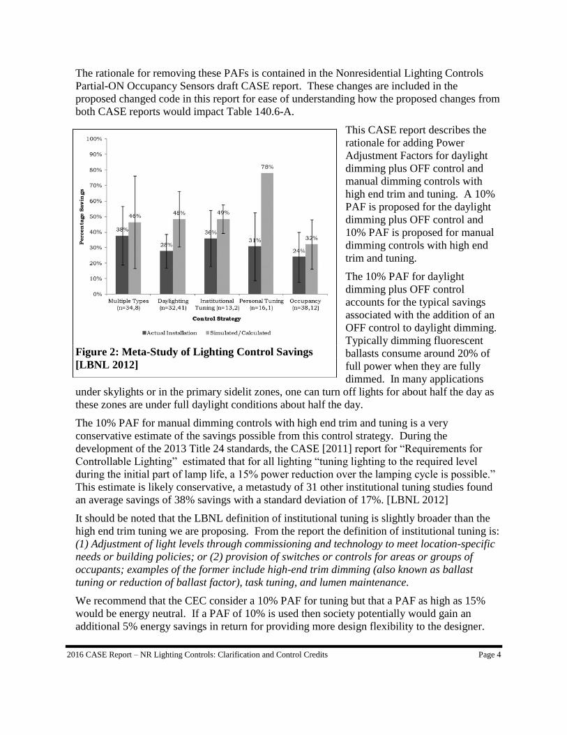
The base case daylight dimming
control strategy is dimming with
lowest power level being 30% at
full dimming and when the PAF is
selected and confirmed via the
acceptance test, the control is
continuous dimming plus off.
Figure 3 (Figure 10 of the ACM)
plots curves of percent of lighting
power for a dimming versus a
dimming plus OFF control
calculated for a space with a 75 fc
setpoint.
Figure 3: Dimming and Dimming plus OFF control
(Fig 10 in NR ACM)
0
0.2
0.4
0.6
0.8
1
1.2
0 10 20 30 40 50 60 70 80 90 100
uncontrolled fc (setpoint = 75 fc)
Fra
cti
on
of
rate
d p
ow
er
continuous
continuous + off
Page 18
2016 CASE Report – NR Lighting Controls: Clarification and Control Credits Page 6
2.1.2 Measure History and Existing Standards
Dimming system flicker requirements Section110.9(b)3. The Title 24 standards have had
requirements to minimizer flicker for over 20 years as it is recognized as a feature of lighting
that is so annoying that it can result in lost energy savings due to the associated controls being
disabled and efficient light sources being removed.
The Title 24 standards have had requirements for flicker starting in the 1988 standards and in
the 1992 standard contained the following definition: “REDUCED FLICKER OPERATION is
the operation of a light, in which the light has a visual flicker less than 30% for frequency and
modulation.” The 1992 Title 24 standards in mandatory Section 119[e] required that dimming
daylighting controls “provide electrical outputs to lamps for reduced flicker operation through
the dimming range and without causing premature lamp failure…”
This requirement remained unchanged until the 2008 Title 24 development process where LED
manufacturers commented that LED systems using pulse width modulation for dimming could
have amplitude modulation as high as 100% but that this did not result in perceptible flicker
because this amplitude modulation was occurring at very high frequencies. After review of the
research on flicker it was determined that flicker was a function of both percent amplitude
modulation (also known as percent flicker) and the frequency at which the amplitude
modulation takes place. In 2008 the definition and the requirement for daylighting controls
were combined so that the requirement for daylighting controls include the following: “If the
device is a dimmer controlling incandescent or fluorescent lamps, provide electrical outputs to
lamps for reduced flicker operation through the dimming range, so that the light output has an
amplitude modulation of less than 30 percent for frequencies less than 200 Hz, and without
causing premature lamp failure.” This requirement was expanded to cover all dimmers
including manual dimmers. Manufacturers have asked how they can comply with the standard
but up to this point were not given guidance on a test method.
Percent Amplitude Modulation of any signal is given by the following equation:
Percent Amplitude Modulation = (Max − Min)
(Max + Min)× 100
During the 2013 Title 24 revision process, the flicker requirement for dimmers and daylight
dimming controls were moved to the California Title 20 Appliance Efficiency Standards
Section 1605.3(l)2 “Self Contained Lighting Controls.” In Section 110.9(b), each lighting
control system has to meet the requirements in the Title 20 standards including those for
reduced flicker operation.
This proposal clarifies that the flicker requirements apply to the entire dimming system
(dimmer, lamps and ballasts or drivers) and applies to all light sources and specifies a test
method for confirming that the source is indeed qualifies as maintaining low flicker operation.
Multi-level control simplification Section 130.1(b)3. The approach of pick one approach out
of five was proposed near the end of the development of the 2013 standards. This format is
similar to approaches taken in voluntary standards where one can pick from a long list (5
options) to obtain extra points. For a mandatory requirement this results in significant added
Page 19
2016 CASE Report – NR Lighting Controls: Clarification and Control Credits Page 7
complexity for little gain. Three out of the five requirements in this section are already
required by other mandatory sections of the standards. It should be noted that one of these five
choices is high end trim tuning. However if one has dimmable lighting that can be tuned,
Section 130.1(a)2C also requires a manual dimmer, one of the other five choices. Thus this
approach provides no effective requirement to tune dimming lighting systems.
Daylighting Controls Calibration Accessibility Section 130.1(d)2D. The 2005 T-24
standards first introduced mandatory daylighting controls. In the 2008 Title 24 standards
(CASE 2006) additional installation and operating requirements were added to the daylighting
controls requirements in response findings from a large sidelighting photocontrols study that
identified common causes of photocontrol failure and poor performance. (HMG 2005) One of
causes of poor system performance, inaccessibility of calibration adjustments was addressed by
Section 131(c) 2Diii: “The location where calibration adjustments are made to the automatic
daylighting control device shall be readily accessible to authorized personnel, or located within
2 feet of a ceiling access panel that is no higher than 11 feet above floor level.”
The question was raised how does a building inspector make sure that the control is readily
accessible to authorized personnel only? The requirement didn’t say that it only had to be
accessible to authorized personnel as in some cases one is not concerned about tampering by
other employees. If one is concerned about authorized people having access one can place the
control behind a locked cover or in a secure room.
In the 2013 standards the code language was changed in the renumbered Section 130.1(d)2Di
to, “Photosensors shall be located so that they are not readily accessible to unauthorized
personnel, and the location where calibration adjustments are made to automatic daylighting
controls shall not be readily accessible to unauthorized personnel.” This would have the
unintended consequence that the calibration adjustments could be inaccessible to anyone
including authorized personnel. In fact this is one of the least expensive ways of making the
control by placing the photosensor and control logic and calibration adjustment controls on a
single unit which can then be located up on the ceiling (which might be 30 feet above the
floor).
The ASHRAE 90.1-2013 Energy Standard in Section 9.4.1.1(e)1 has the following
requirements for the location of calibration controls for photocontrols: “The calibration
adjustments shall be readily accessible.” The function testing requirements in ASHRAE 90.1
has the following requirement for photocontrols in Section 9.4.3(c)3: “The location where
calibration adjustments are made is readily accessible only to authorized personnel.” Thus the
current Title 24 requirements are out of synch with ASHRAE 90.1 and are not aligned with
earlier research on photocontrol performance.
Daylight Dimming Plus OFF Controls PAF Section 140.6(a)2H. The daylighting control
requirements in Section 130.1(d) say this about the minimum light level required at full
daylighting.
i. Automatic daylighting controls shall provide functional multi-level lighting having at least
the number of control steps specified in TABLE 130.1-A.
and
Page 20
2016 CASE Report – NR Lighting Controls: Clarification and Control Credits Page 8
iv. In areas served by lighting that is daylight controlled, when the illuminance received from
the daylight is greater than 150 percent of the design illuminance received from the general
lighting system at full power, the general lighting power in that daylight zone shall be reduced
by a minimum of 65 percent.
Depending on the light source the minimum light output in Table 130.1-A can be as low as
10% for incandescent lighting, as high as 50% for HID (high intensity discharge) lighting and
for incandescents between 20% and 40% on its lowest level. In conjunction with item iv above
this results in fluorescent systems dimming to between 20 and 35% under full daylight
conditions.
The ASHRAE 90.1-2013 standards
have the following minimum light
output requirements for automatic
daylighting responsive controls for
sidelighting in Section 9.4.1.1(e)3
and similar requirements for
toplighting in Section 9.4.1.1(f)2:
The photocontrol shall reduce
electric lighting in response to
available daylight using continuous
dimming or with at least one control
point between 50% and 70% of
design lighting power, a second
control point between 20% and 40%
of design lighting power or the lowest
dimming level the technology allows,
and a third control point that turns
off all the controlled lighting.
Note that the ASHRAE standard does
not require dimming controls but
does require that the controlled
general lighting in the daylit zone
have three different illumination levels plus OFF. The rationale for these requirements is based
on a simulation study conducted by PNNL with assistance from Mudit Saxena. This study
found that there was little difference in the annual lighting savings between multi-level
switching and continuous dimming. However when either control was enhanced by turning
lights completely off under full daylight conditions, this saved approximately another 30% of
lighting energy. These findings are illustrated in Figure 4. For a simulated office building
with a window to wall ratio of 33% and various glazing VT as identified on the x axis
(between 10% and 80%) the entire energy consumption of the building is impacted between
0.6% and 2.5% depending upon window VT and the type of daylighting control. It should be
noted that the prescriptive minimum VT in Title 24 for nonresidential buildings is 42% for
fixed windows and 32% for operable windows. The top two lines in each graph corresponding
Figure 4: ASHRAE 90.1 Daylighting Controls
Comparison
Page 21
2016 CASE Report – NR Lighting Controls: Clarification and Control Credits Page 9
to least energy savings corresponds to multilevel and dimming controls that do NOT switch all
the way OFF. The bottom two lines with greatest energy savings corresponds to dimming or
multilevel switching controls that are turned completely OFF under full daylight conditions.
From these graphs it is readily apparent that the addition of the OFF stage to the daylighting
controls saves approximately another 30% of lighting energy savings when the window VT is
around 40%. The results of this study were compelling and motivated the lighting
subcommittee to approve this control measure.
Manual Dimming Controls with High end Trim Tuning PAF Section 140.6(a)2J. Tuning
of lighting controls is required for daylighting controls as the acceptance tests for daylighting
controls requires adjusting controls under no daylight, partial daylight and full daylight. The
no daylight adjustment protocol essentially tunes the lighting systems for full light output.
During the 2013 Title 24 standards development, one of the largest energy savings measures
was the requirement for controllable lighting (Section 130.1(b)). This requirement essentially
requires dimmable lighting or lighting with enough controls steps that it closely mimics
dimmable lighting. The controllable (dimmable) lighting requirements are required for all
general lighting where the installed lighting power density is greater than 0.5 W/sf.
The rationale for requiring dimmable lighting everywhere, and not just in daylit zones or other
zones where automatic dimming controls would be used, was that controllable lighting
provides savings from tuning in all areas. Since one can only specify and integer value of
luminaires and cannot specify fractions of luminaires in a given space, there will be
opportunities to more closely match the design illuminance of the space by adjusting the light
output of luminaires. The CASE (2011) report “Requirements for Controllable Lighting”
estimated that on average for all locations “tuning lighting to the required level during the
initial part of lamp life, a 15% power reduction over the lamping cycle is possible.”
However in the 2013 standards, there are no mandatory requirements for tuning (outside of the
pick one of 5 choices in Section 130.1(b)) and there are no PAFs for tuning. Thus there are no
requirements for tuning controllable lighting and there are no credits either. Thus the 2013
Title 24 code provides little compulsion or incentive for designers to specify tuning of
controllable lighting.
Remove Three PAF’s in Table 140.6-A The Power Adjustment Factor for Partial ON
occupancy sensing control PAF helped to motivate designers to specify this control type and
for manufacturers to develop a product that met this specification. See the “Nonresidential
Lighting Controls: Partial-ON Occupancy Sensors.” CASE presentation and CASE report on
more detail on where this control is now a mandatory control requirement [CASE, 2014a;
CASE 2014c]
The PAF for manual dimming was introduced to encourage dimmable lighting. Dimmable
lighting is now a mandatory requirement for most general lighting; as a result, the PAF is no
longer needed.
NA7.7.6.2 “Acceptance Tests for High End Trim Tuning of Dimmable Lighting.” This
new acceptance test is added to verify that those lighting systems that are taking the PAF credit
for tuning have effectively been tuned. Though tuning was included in the list of 5 options for
Page 22
2016 CASE Report – NR Lighting Controls: Clarification and Control Credits Page 10
Section 130.1(b)3(A through E), there was no detailed definition of what was required or an
acceptance test to validate that it had been done.
The existing acceptance tests for PAF measures are contained in 2013 Title 24 Standards
Nonresidential Appendix NA7.7.6 “Lighting Controls Installed to Earn a Power Adjustment
Factor (PAF) in Accordance with Section 140.6(a)2.” Given that the requirements were for
fairly basic control strategies, there was little detail to these tests outside of confirming that the
control were installed and appear to be operational. What is proposed for verifying High End
Trim Tuning of Dimmable Lighting requires measuring illumination in accordance with the
methods in the IES handbook and comparing these results with initial design illuminance
levels listed on the construction documents.
A similar tuning proposal has been developed and is under consideration by the ASHRAE 90.1
Energy Standard lighting subcommittee. A similar proposal is being prepared for the energy
and indoor environmental working groups for the ASHRAE 189.1 Standard for the Design of
High-Performance Green Buildings.
2.1.3 Alignment with Zero Net Energy Goals
Many of the features of this proposal are clean-up to the code language that makes it easier to
understand and enforce. However this proposal is also recommending the addition to two
energy savings measures that increase energy efficiency: dimming plus off daylighting controls
and high end trim tuning of lighting systems. As is described in the description of these
measures, both save significant amounts of lighting energy. Both of these measures are
proposed as control credits (power adjustment factors) in the 2016 version of Title 24. These
control credits are intended to familiarize the nonresidential lighting design and construction
industry with this technology on a voluntary basis. This proposal modifies the control credits
and the ACM (alternative compliance method) manual so that there is an established way to
take credit for these two technologies. Besides using these credits for code compliance these
credits can be used to show that a building is more than minimally compliant with Title 24 for
LEED (Leadership in Energy & Environmental Design) certification or for participating in
utility efficiency incentive programs. The end goal is to include these requirements in future
energy codes well in advance of the 2030 target for all new Commercial buildings being ZNE2
and in advance of the 2025 deadline for the executive order that all new California government
buildings are ZNE.3
2.1.4 Relationship to Other Title 24 Measures
Power adjustment factors render it easier to comply with the lighting power allowances in
Section 140.6 because they provide a wattage credit for lighting designs that incorporate the
2 CPUC. CA Energy Efficiency Strategic Plan Update 2011. http://www.cpuc.ca.gov/NR/rdonlyres/A54B59C2-D571-440D-
9477-3363726F573A/0/CAEnergyEfficiencyStrategicPlan_Jan2011.pdf 3 Executive Order B-18-12. http://gov.ca.gov/news.php?id=17506
Page 23
2016 CASE Report – NR Lighting Controls: Clarification and Control Credits Page 11
use of the lighting control technologies specified in table 140.6-A “Lighting Power Density
Adjustment Factors (PAF). The Partial On Occupancy Controls CASE report has
recommended eliminating two Power Adjustment Factors (Partial On Occupant Sensing
Control and Dimming Systems). Removing these control systems from the PAF table makes
sense they are essentially required by a code that in the 2013 Title 24 standards essentially
requires dimming for many spaces in Section 130.1(b) and by the proposal for the 2016
standards for Partial-On Occupancy Sensing Controls mandatory requirements. This proposal
for PAFs for Daylight dimming plus OFF controls and High End Trim Tuning give some
additional flexibility back to the lighting designer.
In any project where a designer is having a hard time achieving compliance from judicious
selection of lighting technology and fixture layout, the designer can specify dimming plus off
daylighting controls and high end trim tuning and have a larger lighting budget for compliance.
Thus this proposal can offset some of the dislocation associated with complying with the new
LPD’s proposed for the 2016 standards while saving additional lighting energy.
2.2 Summary of Changes to Code Documents
The sections below provide a summary of how each Title 24 documents will be modified by
the proposed change. See Section 4 of this report for detailed proposed revisions to code
language.
2.2.1 Catalogue of Proposed Changes
Scope
Table 2 identifies the scope of the code change proposal. This measure will impact the
following areas (marked by a “Yes”).
Table 2: Scope of Code Change Proposal
Mandatory Prescriptive Performance
Compliance
Option
Trade-
Off
Modeling
Algorithms Forms
Yes Yes Yes Yes Yes Yes Yes
Standards
The proposed code change will modify the sections of the California Building Energy
Efficiency Standards (Title 24, Part 6) identified in Table 3.
Page 24
2016 CASE Report – NR Lighting Controls: Clarification and Control Credits Page 12
Table 3: Sections of Standards Impacted by Proposed Code Change
Title 24, Part 6
Section Number Section Title
Mandatory
Prescriptive
Performance
Modify Existing
New Section
100.1 Initial Design Illuminance Mandatory New Definition
110.9(b)3 Dimmers Mandatory Modify Existing
130.1(b) Multi-Level Lighting Controls Mandatory Modify Existing
130.1(d)2D Automatic Daylighting Control Installation
and Operation Mandatory Modify Existing
140.6(a)2 Reduction of wattage through controls Prescriptive Modify Existing
TABLE 140.6-A Lighting Power Density Adjustment Factors
(PAF) Prescriptive Modify Existing
Appendices
The proposed code change will modify the sections of the indicated appendices presented in
Table 4. If an appendix is not listed, then the proposed code change is not expected to have an
effect on that appendix.
Table 4: Appendices Impacted by Proposed Code Change
Standards Joint Appendix JA 1
Section Number Section Title
Modify Existing
New Section
JA1 Glossary Modify Existing
JA10
Test Method for Measuring Flicker of Lighting
Systems and Reporting Requirements New Section
Nonresidential Appendix NA 7 Installation and Acceptance Requirements
Section Number Section Title Modify Existing
New Section
NA7.7.6
Lighting Controls Installed to Earn a Power
Adjustment Factor (PAF) in Accordance with
Section 140.6(a)2 Modify Existing
NA7.7.6.2
Acceptance Tests for High End Trim Tuning of
Dimmable Lighting New Section
Nonresidential Alternative Calculation Method (ACM) Reference Manual
The proposed code change will modify the sections of the Residential or Nonresidential
Alternative Calculation Method References identified in Table 5.
Page 25
2016 CASE Report – NR Lighting Controls: Clarification and Control Credits Page 13
Table 5: Sections of ACM Impacted by Proposed Code Change
Nonresidential Alternative Calculation Method Reference
Section Number Section Title Modify Existing)
New Section
3.2.2.4 Design Illumination Setpoint Modify Existing
5.4.4 Interior Lighting Modify Existing
5.4.5 Daylighting Control Modify Existing
Simulation Engine Adaptations
The proposed code change can be modeled using the current simulation engine. Changes to the
simulation engine are not necessary.
2.2.2 Standards Change Summary
This proposal would modify the following sections of the Building Energy Efficiency
standards as shown below. See Section 4 “Proposed Language” of this report for the detailed
proposed revisions to the standards language.
Changes in Scope
Nothing in this proposal changes the scope of the standards.
Changes in Mandatory Requirements
Section110.9(b)3. This would add clarifying language to the lighting controls
requirement that the flicker requirement applies to entire dimming system (control, lamps
and ballasts or drivers) and not just the controls. It also references a flicker test method
in reference joint appendix JA10. The details of this test method and rationale are
contained in the Residential Lighting Draft CASE report.
Section 130.1(b)3. This proposed change would replace a hard to enforce, confusing
portion of the multi-level lighting controls requirements with a simpler requirement
which is easier to enforce. The confusing portion has a requirement to pick one out of
five requirements for each enclosed are in addition to all other requirements. However
two of the requirements (manual dimming control and demand response) are already
required in many situations. The proposal would require clarify the requirement that
most commonly applies (manual dimming controls for dimmable luminaires). This will
simplify and render this section more enforceable.
Section 130.1(d)2D. More clearly state the requirements for the accessibility of
calibration adjustment control for photocontrol (daylighting control) systems. The
primary purpose of this requirement is to prevent tampering with the photosensor and to
have the calibration controls readily accessible so that adjustments to daylighting controls
can be easily performed by authorized personnel in response to changes in geometry or
reflectance of the interior, changes in occupancy or tasks and in response to requests for
more or less light from occupants.
Page 26
2016 CASE Report – NR Lighting Controls: Clarification and Control Credits Page 14
Changes in Prescriptive Requirements
Add two Power Adjustment Factors in Table 140.6-A for daylighting dimming plus OFF
control and manual dimming with high end trim tuning.
2.2.3 Standards Reference Appendices Change Summary
Reference Joint Appendix JA10
Reference Joint Appendix JA10 “Test Method for Measuring Flicker of Lighting Systems and
Reporting Requirements” describes a test method for quantifying the amount of flicker from
lighting systems. The Title 24 standards have had requirements to minimizer flicker for over
20 years as it is recognized as a feature of lighting that is so annoying that it can result in lost
energy savings due to the associated controls being disabled and efficient light sources being
removed. However until the addition of this appendix there has not been a consistent reliable
test method for enforcing the flicker requirements.
The Title 24 standards have had requirements for flicker starting in the 1988 standards and in
the 1992 standard contained the following definition: “REDUCED FLICKER OPERATION is
the operation of a light, in which the light has a visual flicker less than 30% for frequency and
modulation.” The 1992 Title 24 standards in mandatory Section 119[e] required that dimming
daylighting controls “provide electrical outputs to lamps for reduced flicker operation through
the dimming range and without causing premature lamp failure…”
This requirement remained unchanged until the 2008 Title 24 development process where LED
manufacturers commented that LED systems using pulse width modulation for dimming could
have amplitude modulation as high as 100% but that this did not result in perceptible flicker
because this amplitude modulation was occurring at very high frequencies. After review of the
research on flicker it was determined that flicker was a function of both percent amplitude
modulation (also known as percent flicker) and the frequency at which the amplitude
modulation takes place. In 2008 the definition and the requirement for daylighting controls
were combined so that the requirement for daylighting controls include the following: “If the
device is a dimmer controlling incandescent or fluorescent lamps, provide electrical outputs to
lamps for reduced flicker operation through the dimming range, so that the light output has an
amplitude modulation of less than 30 percent for frequencies less than 200 Hz, and without
causing premature lamp failure.” This requirement was expanded to cover all dimmers
including manual dimmers. Manufacturers have asked how they can comply with the standard
but up to this point were not given guidance on a test method.
Percent Amplitude Modulation of any signal is given by the following equation:
Percent Amplitude Modulation = (Max − Min)
(Max + Min)× 100
During the 2013 Title 24 revision process, the flicker requirement for dimmers and daylight
dimming controls were moved to the California Title 20 Appliance Efficiency Standards
Section 1605.3(l)2 “Self Contained Lighting Controls.” In Section 110.9(b), each lighting
Page 27
2016 CASE Report – NR Lighting Controls: Clarification and Control Credits Page 15
control system has to meet the requirements in the Title 20 standards including those for
reduced flicker operation.
The ENERGY STAR program recognizes that flicker is a concern for the widespread adoption
of efficient lighting products and this is especially an issue when lighting is dimmed as some
(but not all) dimming methods have the potential to increase flicker. However the ENERGY
STAR program only requires that percent flicker and flicker index (a similar metric as percent
flicker) be measured and does not set any requirements based on the results of the
measurements. In addition, the ENERGY STAR program does not require that these results be
filtered by frequency which is needed to address the concerns by the LED industry that the
problems with flicker are a function of both amplitude modulation and frequency; something
California addressed in 2008 by including a frequency specification.4 By including flicker
testing for light sources with the dimming controls they are intended to be used with,
ENERGY STAR explicitly recognized that flicker is not just a function of a particular dimmer
control but is a function of the combination of the dimmer, ballast or driver and light source
and they are combining this information as part of the process for certifying lamps as
ENERGY STAR qualified.
The proposed Reference Joint Appendix JA10 would take the ENERGY STAR flicker protocol
a couple of steps further by specifying the minimum sampling rate, sample duration for
measuring light output and providing specifications and tools for filtering the higher frequency
components of the digitized signal before conducting the percent amplitude modulation
calculations.
The filtering of the high sample rate data is performed mathematically using Fourier Transform
analysis. The details of this manipulation are described in an IEEE paper: (Lehman et al.)
“Proposing Measures of Flicker in the Low Frequencies for Lighting Applications.” The key
steps of the process are to convert the time series data into the frequency domain as a Fourier
series having the form:
To filter the data in a low-pass format, the Fourier series terms that are above the cut-off
frequency are deleted. This modified or truncated Fourier series is then converted back into the
time domain. The filtered time series data is then used to calculate percent amplitude
modulation for frequencies below the cut-off frequency. The proposed Reference Joint
Appendix JA10 requires that percent amplitude modulation be reported for unfiltered data as
well as data filtered with the following cut-off frequencies: 1,000 Hz, 400 Hz, 200 Hz, 90 Hz,
and 40 Hz. The data required for meeting the reduced flicker requirements in Reference Joint
4 The California flicker specification is written to be technology neutral so it does not assume for instance that modulation occurs
at 120 Hz as has been often the case for LED with poorly filtered drivers, but could be at other frequencies as might be the case with an unstable arc of a discharge source.
Page 28
2016 CASE Report – NR Lighting Controls: Clarification and Control Credits Page 16
Appendix JA8.6 is only the percent amplitude modulation at full light output and dimmed to
20% of full light output when the data is filtered for 200 Hz. The rest of the percent amplitude
modulation data is stored in the CEC database and is available to lighting designers who may
want to compare product performance across all of the different frequencies and at the four
dimming levels (100%, 80%, 50% and 20%).
In addition to the summary data, the entity submitting data would be required to submit the
unfiltered raw high frequency digitized light output data which is used to validate the percent
amplitude modulation values submitted to the California Energy Commission.
The “reduced flicker operation” requirements in the current Title 20 appliance standards and
proposed for Reference Joint Appendix JA8 are: “reduced flicker operation is defined as
having percent amplitude modulation (percent flicker) less than 30% at frequencies less than
200Hz.” In addition we are proposing that this definition would be enforced though the test
method in JA10. This flicker requirement is not particularly stringent but prohibits the most
objectionable flicker in light sources complying with JA8. Once flicker data is available for a
broader range of products through this test and list requirement, the Commission may decide
that even more stringent flicker requirements are justified in the future revisions to the
standards.
Flicker can be related headaches
and eyestrain even when the light
source is not perceived to flicker
(Wilkins et al. 1989). Wilkins
compared the number of
headaches reported by office
workers under two types of
fluorescent lamp—a 50Hz AC
lamp with an amplitude
modulation of around 50%, and a
32kHz lamp with a modulation of
around 7%, neither of which gave
perceptible flicker. Subjects
reported an average of 0.52
headaches per week, a value which
halved after the installation of the
high-frequency lighting. These
results apply to frequencies above
the perceptible range of flicker.
Thus it seems prudent to reduce
flicker significantly below the
perceptible range to avoid the
possibility of adverse non-visual
effects.
Performance can also be impacted
Figure 5: Detection and Acceptability of Stroboscopic
Effects (LRC 2012)
Page 29
2016 CASE Report – NR Lighting Controls: Clarification and Control Credits Page 17
by imperceptible flicker. Veitch (1995) found that the visual performance of 48 undergraduate
students was reduced under 60Hz AC lamps compared with 20-60kHz lamps, despite the
absence of perceptible flicker.
More recent research by the Light Research Center (LRC 2012) evaluated stroboscopic effects
from flickering light sources to evaluate both when people notice these effects and what levels
of percent flicker (percent amplitude modulation) were considered unacceptable. The results of
this study are graphed in Figure 5. Overlaid on top of these figures is a rectangle in the upper
left corner; this rectangle indicates the performance characteristics of products that would not
satisfy the Title 24 requirements for “reduced flicker operation,” where amplitude modulation
(percent flicker) is greater than 30% for frequencies less than 200 Hz. This region of
frequencies and amplitude modulation is detectable by at least 80% of the population and the
stroboscopic effects are considered very unacceptable.
Another reference point on the relative
stringency of the reduced flicker
operation requirement is obtained by
comparing this requirement to regions
of frequency and amplitude
modulation that are considered low
risk and no effect for flicker by
Lehman et al (2014). Figure 6 in the
upper left corner overlays the region
not compliant with “reduced flicker
operation” on top of the regions that
are considered low risk by Lehman. It
is readily apparent that the regions of
amplitude modulation and frequency
that do not comply with the T-24
definition of low flicker operation are
well above the region defined as being
low risk for affects from flicker,
indicating that the Title 24
specification may not be stringent
enough.
In support of a proposal to the
California Appliance Standards on LED Replacement Lamp Quality, (PG&E/SDG&E 2013),
flicker testing was conducted on omni-directional LED A-lamps controlled by phase cut
dimmers. The results of these initial tests of filtered amplitude modulation measurements of
LED A lamps indicates that 52% of products tested were considered to achieve “reduced
flicker operation” at full light output and when lamps were dimmed to 20% of full light output.
Figure 6: Low risk and no observable effect
regions for flicker (Lehman et al 2014) overlaid
with region of graph not compliant with
"reduced flicker operation" requirement
Page 30
2016 CASE Report – NR Lighting Controls: Clarification and Control Credits Page 18
In Figure 7, the results
are filtered so that only
the low frequency data
less than 200 Hz is
evaluated for percent
amplitude modulation
(percent flicker). If one
observes the results in
Figure 7, one can see that
13 out of 25 A-lamps are
able to pass the “low
flicker operation”
specification; they have
less than 30% amplitude
modulation at 100 % full
light output and when
dimmed down to 25% of
full light output. Lamp
13 fails for having too much amplitude modulation at full light out and lamps 15 through 25
fail mostly at both dimming levels. These results indicate the cup is both half full and half
empty. Half full in regards to the market being able to provide plenty of products that can
meet the flicker requirements before there is a quantitative metric for flicker. But with half of
the LED products failing the flicker test indicates that the cup is also half empty; these findings
indicate that the market is not self-policing; as has occurred numerous times in the past with
food, drugs, and consumer goods, inferior products are sold into markets without testing,
labeling and minimum standards. It should be noted that 12% or 3 of the samples out of 25
lamps with photometric date filtered for frequencies less than 200 Hz had amplitude
modulation of 100%! Comments that all lamp manufacturers have a quality control expert
with a “golden eye” that detects and prevents problematic flicker do not withstand the scrutiny
of objective physical testing. Clearly some products are significantly exceeding the modest
flicker requirements proposed here, but others are failing badly
Currently the ENERGY STAR test protocol does not have the Fourier method filtering as part
of their test method. The results of the ENERGY STAR test method without filtering bring up
the issues that the CEC addressed in 2008 with the redefinition of “low flicker operation” that
accounts for both amplitude modulation (percent flicker) and frequency. Figure 8 illustrates
for the same A-lamps what happens if the high frequency photometric data is not filtered, only
one product is able keep amplitude modulation less than 30%. Thus unless the manufacturers
of the 52% of the LED products that are passing the proposed California flicker criteria have
filtered their photometric data with a 200 Hz low pass filter they might believe that their
products don’t comply when they actually do satisfy the filtered flicker criteria.
Figure 7: Filtered Flicker Test Data for 25 LED A-lamps
(filtered flicker proposed for CA standards)
Page 31
2016 CASE Report – NR Lighting Controls: Clarification and Control Credits Page 19
We have proposed that
the CEC host a public
domain tool that will
filter the flicker data
automatically for
manufacturers
submitting data.
However for the use of
interested parties, the
CASE team has
attached a sample of
public domain
command language for
use with the
mathematical software
MATLAB in
Appendix A. If test
data is placed in the data format as outlined in TABLE JA-10 (see the JA 10 code language in
Section 4.2) this command language will read in the csv (comma separated variables) data file
and write a similar data file but insert the correct filtered amplitude modulation. The file must
have four strings of data at 100%, 80%, 50% and the greater of 20% or minimum fraction of
light output. The CASE team is looking for feedback on how this system of evaluation works
and whether this approach alleviates the fears of raised about flicker testing.
In terms of repeatability of collecting raw data
for the flicker test, The California Lighting
Technology Center (CLTC) and the Pacific
Northwest National Laboratory (PNNL) tested
four LED A-lamps with phase cut dimmers and
measured percent flicker (the same as
amplitude modulation) at full light output. The
error between the two sets of data is tiny. We
are looking for partners in industry to conduct
the tests in their labs and compare the results with what we have found. Building on findings
from above, we also want to compare both filtered and unfiltered results.
The CASE team has also conducted flicker testing of five fluorescent dimming ballasts which
were controlled with 0-10 VDC controls or digital dimming controls. None of these ballasts
were controlled with phase cut dimmers. All of these dimming ballasts had less than 5%
percent amplitude modulation at both full light output and dimmed down to 20% of full light
output.
Thus we anticipate that once flicker testing is widely conducted, that lamp manufacturers will
be designing most of their products to comply with this standard. This proposal also
encourages the use of NEMA SSL 7A compliant phase cut dimmers as one can test with their
Figure 8: Unfiltered Flicker Test Data for 25 LED A-Lamps
(unfiltered flicker not proposed for CA standards)
Table 6: Comparison of unfiltered
percent flicker results between two test
labs
CLTC PNNL Difference
Product 1 100.00 99.80 0.20%
Product 2 29.79 30.10 -1.05%
Product 3 11.22 11.00 1.96%
Product 4 100.00 100.00 0.00%
0
30
60
90
1 2 3 4 5 6 7 8 9 10 11 12 13 14 15 16 17 18 19 20 21 22 23 24 25
Pe
rce
nt
Flic
ker
(Am
plit
ud
e M
od
ula
tio
n)
Lamp Sample No.
LED A Lamps Unfiltered Flicker Data
100% output 25% output minimum
Page 32
2016 CASE Report – NR Lighting Controls: Clarification and Control Credits Page 20
product with only one NEMA SSL7A compliant dimmer and be considered compliant for all
NEMA 7A qualified dimmers.
Nonresidential Standards AppendixNA7 – Acceptance Tests
This proposal would modify the following sections of the Standards Appendices as shown
below. NA7.6.4 “Acceptance Tests for High End Trim Tuning of Dimmable Lighting.” This
new acceptance test is added to verify that lighting systems claiming the High end Trim
Tuning Power Adjustment factor have tuned the lighting system appropriately.
The high end trim tuning Power Adjustment Factor requires the tuning of light levels to the
initial design illuminance levels tabulated on the construction documents and verified by an
independent third party according to the requirements in the proposed Nonresidential
Appendix NA7.6.4 “Acceptance Tests for High End Trim Tuning of Dimmable Lighting.”
This acceptance tests verifies that all lighting systems receiving the credit have their initial
design illuminance listed on the construction documents, these lighting systems are capable of
high end trim control and that the lighting systems is adjusted so that at full light output the
light levels are within 10% of the listed initial design illuminance.
This will require the creation of a new acceptance testing form.
2.2.4 Nonresidential Alternative Calculation Method (ACM) Reference Manual
Change Summary
This proposal would modify the following sections of the Alternative Calculation Method
(ACM) Reference Manual as shown below. See Section 4.3 ACM Reference Manual of this
report for the detailed proposed revisions to the text of the Alternative Calculation Method
(ACM) Reference Manual.
Proposed changes to the Nonresidential Alternative Compliance Method (ACM) Reference
Manual would specify how to provide credit for Daylight Dimming plus OFF Controls and
Manual Dimming Controls with High End Trim Tuning.
In Section 3.2.2.4 “Design Illumination Setpoint”, specifies that the designer must document
initial design illuminance to take the credit for high end trim tuning PAF. Without this
documentation, the installer is unable to tune the lighting and the acceptance testing
professional is unable to verify the results of high end trim tuning of dimming lighting.
The PAF subsection of Section 5.4.4 “Interior Lighting” describes how the credit for dimming
plus OFF daylighting controls and manual dimming with high end trim tuning are treated
differently in the performance method. The daylighting control credit is simulated using the
daylighting model in the nonresidential performance software whereas lighting that is
receiving a control credit for tuning would have the installed lighting wattage derated by a
factor equal to the PAF.
The Daylighting Control Type subsection in Section 5.4.5 “Daylighting Control” describes the
base case control and the dimming plus OFF daylighting control. The base case daylight
dimming control strategy is dimming with lowest power level being 30% at full dimming and
Page 33
2016 CASE Report – NR Lighting Controls: Clarification and Control Credits Page 21
when the PAF is selected and confirmed via the acceptance test, the control is continuous
dimming plus off.
2.2.5 Compliance Forms Change Summary
The proposed code change will modify the following compliance forms listed below.
NRCC-LTI-02-E –This existing compliance form will be modified to clarify that
continuously dimmable lighting systems must be comply with the low flicker operation
requirements in Section 110.9 as tested in accordance with Reference Joint Appendix
JA-10.
This proposal will require modifying one acceptance form and the creation of a new
acceptance form as described below:
NRCA-LTI-03-A Acceptance testing form (daylighting control acceptance), will need
to be revised to check for lights being turned all the way off when applying for the
daylight dimming plus OFF PAF.
NRCA-LTI-04-A – This new form will be created to support the acceptance test
contained in Appendix NA7.6.4 “Acceptance Tests for High End Trim Tuning of
Dimmable Lighting.”
2.2.6 Simulation Engine Adaptations
The simulation engine does not need to be modified as it can already apply lighting power
adjustment factors associated with pre-calculated PAF’s and it already has a rudimentary
daylighting simulation capability. What would change are the rule sets for the credit for high
end tuning and how credit is given for dimming plus OFF controls.
2.2.7 Other Areas Affected
No other areas affected.
2.3 Code Implementation
2.3.1 Verifying Code Compliance
Most of the changes can be verified using slightly modified existing compliance forms and
acceptance forms. The PAF for high end trim tuning would result in the most changes as it
requires:
The designer to place initial design illuminances directly on the plans or on a lighting
schedule that is part of the construction documents.
Requires the contractor to adjust the high end trim settings to match the initial design
illuminance levels
An acceptance testing professional to retest and fill out the acceptance forms.
Page 34
2016 CASE Report – NR Lighting Controls: Clarification and Control Credits Page 22
2.3.2 Code Implementation
The main challenge to code implementation is the issue of acceptance testing. See more
discussion below.
2.3.3 Acceptance Testing
The high end trim tuning Power Adjustment Factor requires the tuning of light levels to the
initial design illuminance levels tabulated on the construction documents and verified by an
independent third party according to the requirements in the proposed Nonresidential
Appendix NA7.6.4 “Acceptance Tests for High End Trim Tuning of Dimmable Lighting. This
acceptance tests verifies that all lighting systems receiving the credit have their initial design
illuminance listed on the construction documents, these lighting systems are capable of high
end trim control and that the lighting systems is adjusted so that at full light output the light
levels are within 10% of the listed initial design illuminance.
The Acceptance tests were introduced in the 2005 version of the Title 24 standards. The
original intent of the acceptance tests was to provide to the installer of setup contractor a series
of brief tests that would evaluate common failure modes and give direct feedback to the
installing contractor whether the control was performing to the intent of the energy code. The
contractor would fix or adjust any control that failed the acceptance test until it passed. Under
the 2013 standards this mastery method approach towards controls was replaced with a third
party inspector approach that disintegrates the original direct feedback intent of the acceptance
tests.
The challenge of the acceptance testing of high end trim tuning is that one person is adjusting
the lights and another person if verifying compliance with acceptance tests. The calculated
average illuminance of the space is sensitive to where the illumination measurements are
collected. Some of this variability is reduced by using a common method (the illumination
measurement locations and illumination calculations as described in Chapter 9 of the IES
Lighting Handbook 10th Edition. For small spaces this is not an issue as there are a limited
number of locations where one can take the measurements. However as described in the IES
Handbook, one can sample illuminance readings in a couple of locations in a large space and
apply this sampled illuminance to the rest of the space. If the third party acceptance testing
verification takes measurements at other sampled locations they may get different
illuminances.
Rather than having the acceptance testing professional re-measure all the illuminances in the
space used for tuning, it would be more desirable if the installation or tuning contractor filled
out the acceptance form and the acceptance testing professional review the forms and take
sample measurements where the illumination measurements can be repeatedly and easily
defined.
Page 35
2016 CASE Report – NR Lighting Controls: Clarification and Control Credits Page 23
2.4 Issues Addressed During IOU CASE Development Process
The Statewide CASE Team solicited feedback from a variety of stakeholders when developing
the code change proposal presented in this report. In addition to personal outreach to key
stakeholders, the Statewide CASE Team has also been communicating with the stakeholders in
the ASHRAE 90.1 code development process. As mentioned earlier, the ASHRAE 90.1-2013
energy standard requires multi-level plus OFF daylighting controls as a mandatory lighting
control measure and the high end trim tuning proposal is under consideration by the ASHRAE
90.1 lighting subcommittee. The issues that were addressed during development of the code
change proposal are summarized below.
Daylight dimming plus OFF: won’t occupants in a space think that the lights are
broken if they enter a room with full daylighting, try to switch the lights on but they do
not turn on? The response to this question is that occupancy sensors were
disconcerting at first but now people are used to them and understand how they work.
Regular occupants in a space will get used to the system and explain to newcomers how
the control works. Given that this control is required by ASHRAE 90.1-2013, a critical
mass of new buildings will render this commonplace. In this case ASHRAE 90.1 is
leading on daylighting controls and Title 24 is following. This proposal is
recommending this control strategy only as a voluntary PAF, for a building designer
that either wants to show how far they can exceed Title 24 or in return for higher LPDs.
High end trim tuning. Lighting designers don’t want the liability of placing design light
levels on construction documents. As a control credit, this is a voluntary measure for
those designers that want either more lighting power or bragging rights for exceeding
Title 24 by a larger margin for receiving LEED credits or utility incentives.
Calculating and placing the design illuminances on the construction documents is good
lighting practice performed by many lighting designers.
How does someone define average task illuminance? Use the measurement and
calculation procedures as described in Chapter 9 of the IES Lighting Handbook 10th
Edition.
3. MARKET ANALYSIS
The Statewide CASE Team performed a market analysis with the goals of identifying current
technology availability, current product availability, and market trends. The Statewide CASE
Team considered how the proposed standard may impact the market in general and individual
market players.
3.1 Market Structure
Dimming plus off controls are available from multiple manufacturers and can also be
programmed into lighting control panels with software changes. High end trim controls are
available on many stand-alone dimmers.
Page 36
2016 CASE Report – NR Lighting Controls: Clarification and Control Credits Page 24
3.2 Market Availability and Current Practices
Dimming plus off controls are used by one of the largest owners of daylit real estate, Wal-
Mart. The standard Wal-Mart store design uses skylights with dimming fluorescent lights that
dim in response to daylight availability and turn off when the daylight illuminance exceeds the
design illuminance. COSTCO uses a multi-level plus OFF switching control for many of its
stores. However outside of these large end-users of daylighting controls most of the smaller
end-users and many designers have not yet made the transition to dimming plus OFF controls.
3.3 Useful Life, Persistence, and Maintenance
The useful life persistence and maintenance of daylight dimming plus off controls are
comparable to the daylight dimming only controls they replace. For fluorescent lighting
systems, it is expected that the burning hours of the lamps will be reduced as switching on an
off a lamp reduces it burning hours. However if the lamp is turned off for more than 90
minutes, the actual time between replacements increases by switching them off. With
appropriate use of illuminance deadband and time delay algorithms, the daylight switching of
lamps is reduced to several times per day.
High end trim is built into many stand-alone dimmers and is a capability inherent in many
lighting control panels. On stand-alone dimmers the trim control is located under the switch
cover and thus not accessible to unauthorized building occupants. For lighting control panels
adjustments of high end trim is usually accessible (understandable) to a few people who are
maintaining the lighting control system. Thus the persistence of the high end trim is high.
Given that lumen depreciation is low for many modern light sources, there is not a need to
adjust high end trim settings between lamp replacements. This may change with greater use of
LED lighting being served by drivers that do not automatically adjust in response to burn hours
or to a closed loop lumen maintenance control.
3.4 Market Impacts and Economic Assessments
3.4.1 Impact on Contractors
Simpler code requirements (such as eliminating the one out of five requirements in Section
130.1(b)) will render it easier to comply and easier to enforce. Added control credits will
allow more equipment to be installed (both luminaires and controls) which increases bill able
work for contractors. The tuning proposal increases the amount of labor on a job and generates
work lighting acceptance test professionals.
3.4.2 Impact on Building Designers
Simpler code will render it easier to comply. Added PAFs provide more design flexibility to
comply with code. Some lighting designers may be concerned about increased liability
associated with placing design light levels on design documents even though this is good
design practice.
Page 37
2016 CASE Report – NR Lighting Controls: Clarification and Control Credits Page 25
3.4.3 Impact on Occupational Safety and Health
The proposed code change does not alter any existing federal, state, or local regulations
pertaining to safety and health, including rules enforced by the California Department of
Occupational Safety and Health (Cal/OSHA). All existing health and safety rules will remain
in place. Complying with the proposed code change is not anticipated to have any impact on
the safety or health occupants or those involved with the construction, commissioning, and
Most of the proposed code changes are not expected to have an impact on occupational safety
and health. The requirement for calibration adjustments being readily accessible increases
occupational safety as it avoids the need for climbing up to the ceiling level to make
photocontrol adjustments.
3.4.4 Impact on Building Owners and Occupants
Since this measure is cost-effective, the building owner who pays their energy bills is reducing
their energy costs more than their mortgage costs are for the cost of the measure (i.e. there are
experiencing net cost savings). For building occupants that are paying for their energy bills,
since the measure saves more energy cost on a monthly basis than the measure costs on the
mortgage as experiences by the building owner, the pass-through of added mortgage costs into
rents is less than the energy cost savings experienced by occupants. Impact on Retailers
(including manufacturers and distributors)
3.4.5 Impact on Energy Consultants
Simpler code will render it easier to document compliance. Power adjustment factors increase
the complexity of documentation but this a voluntary effort when the owner or designers are
looking for more lighting power allowances or they are trying to fully document how more
stringent their design is than the minimal requirements of the code for LEED or other building
efficiency certification.
3.4.6 Impact on Building Inspectors
As compared to the overall code enforcement effort, this measure has negligible impact on the
effort required to enforce the building codes. However, the portion of this proposal that
simplifies the code will render it easier to enforce.
3.4.7 Impact on Statewide Employment
When the PAFs are used they generate more work for contractors. High end tuning requires
more labor as it requires that each space taking the credit have the high end trim tuned to the
design light levels defined for that space. In addition this tuning effort must be verified by an
acceptance testing professional, which generates even more work.
Impact on equipment retailers (including manufacturers and distributors): The
Power Adjustments help develop a market for controls that have high end trim and for
dimming plus off photocontrols. This slightly increases overall market activity but
should have a large impact on these two control categories. There is a small cost on
Page 38
2016 CASE Report – NR Lighting Controls: Clarification and Control Credits Page 26
manufacturers to conduct flicker testing on products they sell in California. This cost is
small as the cost is defrayed across all the units they sell in California. For LEDs the
flicker testing can be combined with te flicker testing required for ENERGY STAR
certification.
Impact on energy consultants: no net impact
Impact on building inspectors: Statewide Employment Impacts: as mentioned above
on the impact on contractors,
Impacts on the potential increase or decrease of investments in California: similar to
other lighting control credits, these lighting control credits may spur investment and
innovation by California based lighting control companies.
Impacts on incentives for innovations in products, materials or processes: Since
proposed controls credits are performance based, this allows for equipment suppliers to
develop new technologies that meet the requirements more effectively, more
inexpensively and potentially providing additional amenity in conjunction with the new
functionality.
Impacts on the State General Fund, Special Funds and local government: these
voluntary PAFs allow for the installation of more equipment in buildings which increases
construction costs and thus increases taxes associated with the valuation of new projects.
Cost of enforcement to State Government and local governments: the net impact of
this proposal is to reduce complexity of the code and thus slightly reduce the cost of
enforcement.
Impacts on migrant workers; persons by age group, race, or religion: This proposal
and all measures adopted by CEC into Title 24, part 6 do not advantage or discriminate in
regards to race, religion or age group.
3.5 Economic Impacts
As control credits this proposal has limited impacts on the life cycle cost of buildings.
However the addition of control credits (PAFs) provides more flexibility to the building
designer to add more lighting in exchange for more controls.
3.5.1 Creation or Elimination of Jobs
As a lighting control measure allows more lights and more controls to be installed the net
employment impact is to employ more electricians and to sell more lighting products.
3.5.2 Creation or Elimination of Businesses within California
The Lighting Power Adjustment Factors have had a long history of creating the conditions for
innovative companies to open up shop in California. The occupancy sensor and daylighting
control PAF’s in the 1992 Title 24 standards helped generate a market for these control types.
Thus it is not surprising that a number of controls manufacturers were headquartered in
Page 39
2016 CASE Report – NR Lighting Controls: Clarification and Control Credits Page 27
California. More recently the requirement for multi-level controls created a market for these
types of controls.
3.5.3 Competitive Advantages or Disadvantages for Businesses within California
The Title 24 energy efficiency standards have for years led the rest of the country and the rest
of the world. Many requirements in Title 24 have been adopted by the ASHRAE 90.1 and
IECC energy codes in the United States and other codes overseas. Both high end trim and
daylight dimming plus off have been used voluntarily by advanced design teams and by
companies with large real estate holdings. Manufacturers and designers in California have a
leg up on their competitors by having products and service that incorporate reliable energy
savings techniques
3.5.4 Increase or Decrease of Investments in the State of California
The lighting controls business has become increasingly globalized so that it is hard to predict
just what fraction of increased lighting control investments will be invested in California but it
overall direction is positive in terms of more investment in California lighting firms.
3.5.5 Incentives for Innovation in Products, Materials, or Processes
Since proposed controls credits are performance based, this allows for equipment suppliers to
develop new technologies that meet the requirements more effectively, more inexpensively and
potentially providing additional amenity in conjunction with the new functionality.
3.5.6 Effects on the State General Fund, State Special Funds and Local
Governments
To the extent that the Power Adjustment Factors allow designers to install lighting power with
more equipment (luminaires and controls) costs, there would be slightly more sales tax and
property tax collected. However this is negligible in the context of overall new construction
project costs.
3.5.6.1 Cost of Enforcement
Cost to the State
As an update to the 2016 Title 24 standards the impact to the state to enforce this change to the
standard is negligible. If approved, the state government (CEC) would be involved in the
updates to the standards and the reference appendices, the ACM, and the compliance manuals.
This change is small as compared to the other changes in the standard and the incremental
labor is an even smaller faction of the total effort expended.
Cost to Local Governments
The clarification and simplification components of this proposal reduce the cost of code
enforcement for local jurisdictions. This impact is small. Power adjustment factors add
complexity to the code but as we are removing two PAF controls and adding two control types
Page 40
2016 CASE Report – NR Lighting Controls: Clarification and Control Credits Page 28
the overall impact should be a wash on local government while providing added flexibility for
designers and preparing these code requirements for future versions of the standards.
3.5.7 Impacts on Specific Persons
This proposal and all measures adopted by CEC into Title 24, part 6 do not advantage or
discriminate in regards to race, religion or age group.
This proposal is advantageous to commercial building tenants as it reduces the cost of utilities
which are typically paid by tenants. Since the measure saves more energy cost on a monthly
basis than the measure costs on the mortgage as experienced by the building owner, the pass-
through of added mortgage costs into rents is less than the energy cost savings experienced by
tenants.
This proposal and all measures adopted by CEC into Title 24, part 6 are not expected to have
an impact on commuters. This proposal does not advantage nor disadvantage infill projects.
Page 41
2016 CASE Report – NR Lighting Controls: Clarification and Control Credits Page 29
4. PROPOSED LANGUAGE
The proposed changes to the Standards, Reference Appendices, and the ACM Reference
Manuals are provided below. Changes to the 2013 documents are marked with underlining
(new language) and strikethroughs (deletions).
4.1 Standards
Section 100.1 will be revised in the following manner:
SECTION 100.1 – DEFINITIONS AND RULES OF CONSTRUCTION
LIGHTING definitions:
HIGH END TRIM TUNING is a lighting control strategy in which the maximum light output of an individual or
group of luminaires is adjusted to provide the appropriate amount of light for a space, task or area.
INITIAL DESIGN ILLUMINANCE is the designed average illuminance (footcandles or lux) on the task surface,
provided by a new lighting system. Initial design illuminance is higher than maintained design illuminance as light
loss factors due to aging of the system are not applied.
Section 110.9(b)3 will be revised in the following manner:
3. Dimmers shall meet all requirements for Dimmer Control devices in the Title 20 Appliance Efficiency
Regulations. The entire dimming system including light sources (lamps or light engines), ballasts or
drivers, if applicable, and dimming control shall be designed so the combined performance of the dimming
system results in light amplitude modulation (percent flicker) of less than 30 percent for frequencies less
than 200 Hz as measured and documented according to the Test Method for Measuring Flicker of Lighting
Systems and Reporting Requirements in Reference Joint Appendix JA10. The dimming system shall be
able to dim the light source without causing premature failure of the light source.
Section 130.1(b) will be revised in the following manner:
(a) Area Controls.
1. All luminaires shall be functionally controlled with manually switched ON and OFF lighting controls. Each
area enclosed by ceiling-height partitions shall be independently controlled.
EXCEPTION to Section 130.1(a)1: Up to 0.2 watts per square foot of lighting in any area within a
building may be continuously illuminated during occupied times to allow for emergency egress, if:
A. The area is designated an emergency egress area on the plans and specifications submitted to the
enforcement agency under Section 10-103(a)2 of Part 1; and
B. The control switches for the egress lighting are not accessible to unauthorized personnel.
2. The lighting controls shall meet the following requirements:
A. Be readily accessible; and
B. Be operated with a manual switch that is located in the same room or area with the lighting that is
controlled by that lighting control; and
Page 42
2016 CASE Report – NR Lighting Controls: Clarification and Control Credits Page 30
C. If controlling dimmable luminaires, be a dimmer switch that allows manual ON and OFF functionality,
and is capable of manually controlling lighting through all lighting control steps that are required in
Section 130.1(b).
EXCEPTION 1 to Section 130.1(a)2: In malls, auditoriums, retail and wholesale sales floors, industrial
facilities, convention centers, and arenas, the lighting control shall be located so that a person using the
lighting control can see the lights or area controlled by that lighting control, or so that the area being lit is
annunciated.
EXCEPTION 2 to Section 130.1(a)2: Public restrooms having two or more stalls may use a manual
switch not accessible to unauthorized personnel.
(b) Multi-Level Lighting Controls. The general lighting of any enclosed area 100 square feet or larger, with a
connected lighting load that exceeds 0.5 watts per square foot shall meet the following requirements:
1. Lighting shall have the required number of control steps and meet the uniformity requirements in
accordance with TABLE 130.1-A; and
2. Multi-level lighting controls shall not override the functionally of other lighting controls required for
compliance with Sections 130.1(a), and (c) through (e); and
3. Dimmable luminaires shall be controlled according to Section 130.1(a)2C.
3. Each luminaire shall be controlled by at least of one of the following methods:
A. Manual dimming meeting the applicable requirements of Section 130.1(a)
B. Lumen maintenance as defined in Section 100.1
C. Tuning as defined in Section 100.1
D. Automatic daylighting controls in accordance with Section 130.1(d)
E. Demand responsive lighting controls in accordance with Section 130.1(e)
EXCEPTION 1 to Section 130.1(b): Classrooms, with a connected general lighting load of 0.7 watts per
square feet and less, shall have at least one control step between 30-70 percent of full rated power.
EXCEPTION 2 to Section 130.1(b): An area enclosed by ceiling height partitions that has only one luminaire
with no more than two lamps.
Section 130.1(c)5 will be revised in the following manner:
5. Areas where Occupant Sensing Controls are required to shut OFF All Lighting. In offices 250
square feet or smaller, multipurpose rooms of less than 1,000 square feet, classrooms of any size, and
conference rooms of any size, lighting shall be controlled with occupant sensing controls to
automatically shut OFF all of the lighting when the room is unoccupied. The occupant sensing controls
shall function either as a:
A. Partial-On Occupant Sensor, with the automatic ON level set between 50-70 percent of full rated
power, OR
b. Vacancy Sensor, where all lighting responds to a manual ON input only.
In addition, controls shall be provided that allow the lights to be manually shut-OFF in accordance with
Section 130.1(a) regardless of the sensor status.
EXCEPTION to Section 130.1(c)5: Areas that do not meet the multi-level requirements of
Section 130.1(b) shall operate using either Occupant Sensor or Vacancy Sensor control methods.
Page 43
2016 CASE Report – NR Lighting Controls: Clarification and Control Credits Page 31
Section 130.1(d)2D will be revised in the following manner
D. Automatic Daylighting Control Installation and Operation. For luminaires in daylight zones,
automatic daylighting controls shall be installed and configured to operate according to all of the
following requirements:
i. Photosensors shall be located so that they are not readily accessible to unauthorized personnel.,
and the The location where calibration adjustments are made to automatic daylighting controls
shall not be readily accessible to unauthorized personnel but may be inside a locked case or under
a cover which requires a tool for access.
Section 140.6(a)2 will be revised as follows.
2. Reduction of wattage through controls. In calculating actual indoor Lighting Power Density, the
installed watts of a luminaire providing general lighting in an area listed in TABLE 140.6-A may be
reduced by the product of (i) the number of watts controlled as described in TABLE 140.6-A, times (ii) the
applicable Power Adjustment Factor (PAF), if all of the following conditions are met:
A. An Installation Certificate is submitted in accordance with Section 130.4(b); and
B. Luminaires and controls meet the applicable requirements of Section 110.9, and Sections 130.0
through 130.5; and
C. The controlled lighting is permanently installed general lighting systems and the controls are
permanently installed nonresidential-rated lighting controls. (Thus, for example, portable lighting,
portable lighting controls, and residential rated lighting controls shall not qualify for PAFs.)
When used for determining PAFs for general lighting in offices, furniture mounted luminaires that
comply with all of the following conditions shall qualify as permanently installed general lighting
systems:
i. The furniture mounted luminaires shall be permanently installed no later than the time of building
permit inspection; and
ii. The furniture mounted luminaires shall be permanently hardwired; and
iii. The furniture mounted lighting system shall be designed to provide indirect general lighting; and
iv. Before multiplying the installed watts of the furniture mounted luminaire by the applicable PAF,
0.3 watts per square foot of the area illuminated by the furniture mounted luminaires shall be
subtracted from installed watts of the furniture mounted luminaires; and
v. The lighting control for the furniture mounted luminaire complies with all other applicable
requirements in Section 140.6(a)2.
D. At least 50 percent of the light output of the controlled luminaire is within the applicable area listed in
TABLE 140.6-A. Luminaires on lighting tracks shall be within the applicable area in order to qualify
for a PAF.
E. Only one PAF from TABLE 140.6-A may be used for each qualifying luminaire. PAFs shall not be
added together unless allowed in TABLE 140.6-A.
F. Only lighting wattage directly controlled in accordance with Section 140.6(a)2 shall be used to reduce
the calculated actual indoor Lighting Power Densities as allowed by Section 140.6(a)2. If only a
portion of the wattage in a luminaire is controlled in accordance to Section 140.6(a)2, then only that
portion of controlled wattage may be reduced in calculating actual indoor Lighting Power Density.
Page 44
2016 CASE Report – NR Lighting Controls: Clarification and Control Credits Page 32
G. Lighting controls used to qualify for a PAF shall be designed and installed in addition to manual,
multi-level, and automatic lighting controls required in Section 130.1, and in addition to any other
lighting controls required by any provision of Part 6.
EXCEPTION to Section 140.6(a)2G: Lighting controls designed and installed for the sole purpose of
compliance with Section 130.1(b)3 may be used to qualify for a PAF, provided the lighting controls
are designed and installed in addition to all manual, and automatic lighting controls otherwise required
in Section 130.1.
H. To qualify for the PAF for a Partial-ON Occupant Sensing Control in TABLE 140.6-A, a Partial-On
Occupant Sensing Control shall meet all of the following requirements:
i. The control shall automatically deactivate all of the lighting power in the area within 30 minutes
after the room has been vacated; and
ii. The first stage shall automatically activate between 30-70 percent of the lighting power in the area
and may be a switching or dimming system; and
iii. The second stage shall require manual activation of the alternate set of lights, and this manual-ON
requirements shall not be capable of conversion from manual-ON to automatic-ON functionality
via manual switches or dip switches; and
iv. Switches shall be located in accordance with Section 130.1(a) and shall allow occupants to
manually do all of the following regardless of the sensor status: activate the alternate set of lights
in accordance with item (iii); activate 100 percent of the lighting power; and deactivate all of the
lights.
H. To qualify for the PAF for daylight dimming plus off control, the daylight control and controlled
luminaires must be capable of continuous dimming in response to daylight availability and to turn
lights completely OFF when full daylight is available in the daylit zone. Only those luminaires in the
primary sidelit daylit zone and the skylit daylit zone qualify for this PAF.
I. To qualify for the PAF for an occupant sensing control controlling the general lighting in large open
plan office areas above workstations, in accordance with TABLE 140.6-A, the following requirements
shall be met:
i. The open plan office area shall be greater than 250 square feet; and
ii. This PAF shall be available only in office areas which contain workstations; and
iii. Controlled luminaires shall only be those which provide general lighting directly above the
controlled area, or furniture mounted luminaires that comply with Section 140.6(a)2 and provide
general lighting directly above the controlled area; and
iv. Qualifying luminaires shall be controlled by occupant sensing controls that meet all of the
following requirements, as applicable:
a. Infra-red sensors shall be equipped by the manufacturer, of fitted in the field by the installer,
with lenses or shrouds to prevent them from being triggered by movement outside of the
controlled area.
b. Ultrasonic sensors shall be tuned to reduce their sensitivity to prevent them from being
triggered by movements outside of the controlled area.
c. All other sensors shall be installed and adjusted as necessary to prevent them from being
triggered by movements outside of the controlled area.
Page 45
2016 CASE Report – NR Lighting Controls: Clarification and Control Credits Page 33
J. To qualify for the PAF for a Manual Dimming Controls with High End Trim Tuning System PAF or a
Multiscene Programmable Dimming System PAF in TABLE 140.6-A, the following requirements
shall be met:
i. the lighting shall be controlled with a control that can be manually operated by the user;
ii. the maximum output of the controlled lighting is capable of being adjusted for high end trim
tuning;
iii. Initial Design Illuminance is listed on construction documents for all spaces taking the PAF;
iv maximum lighting output is adjustable and is tuned so that average measured illuminance from the
controlled lighting is no greater than 110% of the Initial Design Illuminance for that space as
verified by the acceptance test in the nonresidential standards appendix NA7.7.6.2 “Acceptance
Tests for High End Trim Tuning of Dimmable Lighting.”
K. To qualify for the PAF for a Demand Responsive Control in TABLE 140.6-A, a Demand Responsive
Control shall meet all of the following requirements:
i. The building shall be 10,000 square feet or smaller; and
ii. The controlled lighting shall be capable of being automatically reduced in response to a demand
response signal; and
iii. Lighting shall be reduced in a manner consistent with uniform level of illumination requirements
in TABLE 130.1-A; and
iv. Spaces that are non-habitable shall not be used to comply with this requirement, and spaces with a
lighting power density of less than 0.5 watts per square foot shall not be counted toward the
building’s total lighting power.
L. To qualify for the PAF for Combined Manual Dimming plus Partial-ON Occupant Sensing Control in
TABLE 140.6-A, (i) the lighting controls shall comply with the applicable requirements in Section
140.6(a)2J; and (ii) the lighting shall be controlled with a dimmer control that can be manually
operated, or with a multi-scene programmable control that can be manually operated.
Page 46
2016 CASE Report – NR Lighting Controls: Clarification and Control Credits Page 34
Table 140.6-A will be revised in the following manner:
TABLE 140.6-A LIGHTING POWER DENSITY ADJUSTMENT FACTORS (PAF)
TYPE OF CONTROL TYPE OF AREA FACTOR
a. To qualify for any of the Power Adjustment Factors in this table, the installation shall comply with the applicable requirements in
Section 140.6(a)2
b. Only one PAF may be used for each qualifying luminaire unless combined below.
c. Lighting controls that are required for compliance with Part 6 shall not be eligible for a PAF
1. Partial-ON Occupant Sensing Control Any area ≤ 250 square feet enclosed by floor-to-ceiling partitions;
any size classroom, conference or waiting room. 0.20
1. Daylight Dimming plus OFF Control Luminaires in skylit daylit zone or primary sidelit daylit zone
0.10
2. Occupant Sensing Controls in Large
Open Plan Offices
In open plan offices > 250 square feet: One sensor
controlling an area that is:
No larger than 125 square feet 0.40
From 126 to 250 square feet 0.30
From 251 to 500 square feet 0.20
3. Dimming
System
Manual Dimming Hotels/motels, restaurants, auditoriums, theaters
0.10
Multiscene Programmable 0.20
3 Manual Dimming Controls with High End
Trim Tuning.
Luminaires in non-daylit areas. PAF is additive with other control
PAFs. 0.10
4. Demand Responsive Control All building types less than 10,000 square feet.
Luminaires that qualify for other PAFs in this table may also qualify
for this demand responsive control PAF 0.05
5. Combined Manual Dimming plus Partial- ON Occupant Sensing Control
Any area ≤ 250 square feet enclosed by floor-to-ceiling partitions; any size classroom, conference or waiting room
0.25
Page 47
2016 CASE Report – NR Lighting Controls: Clarification and Control Credits Page 35
4.2 Reference Appendices
Appendix JA1 – Glossary
ANSI C82.2 is the American National Standard for Lamp Ballasts –Method of Measurement for Fluorescent
Lamp Ballasts (ANSI C82.2:2002)
CIE 53 is the International Commission on Illumination (Commission Internationale de l’Eclairage) document
titled “Methods of characterizing the performance of radiometers and photometers,” Publication CIE 53:1982.
10 CFR 430 Subpart B, Appendix Q is a section from the Code of Federal Regulations entitled 10 CFR Part
430, Subpart B – Test Procedures, with Appendix Q entitled, “Fluorescent Lamp Ballasts.”
10 CFR 430 Subpart B, Appendix R is a section from the Code of Federal Regulations entitled 10 CFR Part
430, Subpart B - Test Procedures, with Appendix R entitled, “Uniform Test Method for Measuring Average Lamp
Efficacy (LE), Color Rendering Index (CRI), and Correlated Color Temperature (CCT) of Electric Lamps.”
10 CFR 430 Subpart B, Appendix W is a section from the Code of Federal Regulations entitled 10 CFR Part
430, Subpart B – Test Procedures, with Appendix W entitled, “Uniform Test Method for Measuring the Energy
Consumption of Medium Base Compact Fluorescent Lamps.”
10 CFR 430 Subpart B, Appendix BB is a forthcoming section from the Code of Federal Regulations (expected
DOE adoption in late Fall 2014) entitled 10 CFR Part 430, Subpart B – Test Procedures, with Appendix BB
entitled, “Uniform Test Method for Measuring the Input Power, Lumen Output, Lamp Efficacy, Correlated Color
Temperature (CCT), Color Rendering Index (CRI), Time to Failure, and Standby Mode Power of Integrated
Light-Emitting Diode (LED) Lamps.”
IES TM-15-11 is the Illuminating Engineering Society document titled, “Luminaire Classification Systems for
Outdoor Luminaires.” (IES TM-15-11)
IES LM-9 is the Illuminating Engineering Society document titled, “Electrical and Photometric Measurements of
Fluorescent Lamps.” (IES LM-9-2009)
IES LM-20 is the Illuminating Engineering Society document titled “Photometric Testing of Reflector-Type
Lamps – Incandescent Lamps.” (IES LM-20-13)
IES LM-45, is the Illuminating Engineering Society document titled, “Electrical and Photometric Measurements
of General Service Incandescent Filament Lamps.” (IES LM-45-09)
IES LM-46, is the Illuminating Engineering Society document titled, “Photometric Testing of Indoor Luminaires
Using High Intensity Discharge or Incandescent Filament Lamps.” 2004. (IES-LM-46-12)
IES LM-51, is the Illuminating Engineering Society document titled, “Electrical and Photometric Measurements
of High Intensity Discharge Lamps.” (IES LM-51-13)
IES LM-66, is the Illuminating Engineering Society document titled, “Electrical and Photometric Measurements
of Single-Ended Compact Fluorescent Lamps.” (IES LM66-11)
IES LM-79-08 is the Illuminating Engineering Society document titled, “IES Approved Method for the Electrical
and Photometric Measurements of Solid-State Lighting Products.” (IES LM 79-08)
IES LM-82-08 is the Illuminating Engineering Society document titled, “LED Light Engines and LED Lamps for
Electrical and Photometric Properties as a Function of Temperature.” (IES LM 82-12)
Page 48
2016 CASE Report – NR Lighting Controls: Clarification and Control Credits Page 36
Appendix JA10 Test Method for Measuring Flicker of Lighting Systems and
Reporting Requirements
This test method quantifies flicker from lighting systems which may include all of the
following components: lamps, ballasts or drivers and dimming controls. This test method
measures the fluctuation of light from lighting systems and processes this signal to quantify
flicker as a percent amplitude modulation (percent flicker) below a given cut-off frequency.
High frequency components of the signal above the cut-off frequency are filtered out. Since
this test method is measuring the relative fluctuation of light, the test can be performed using
either absolute photometry or relative photometry. The flicker of lighting components shall be
tested according to this method, or by a method approved by the Executive Director.
JA10.1 Equipment Combinations
Flicker measurements of a phase cut dimmer controlling an incandescent line voltage lamp
shall be considered representative of that dimmer with any line voltage incandescent lamp.
Flicker measurements of a phase cut dimmer controlling a transformer for low voltage
incandescent lamps shall be considered representative of only that combination of dimmer and
transformer with any incandescent lamp.
Flicker measurements of all non-incandescent lamp sources controlled by a phase cut dimmer
shall be considered representative of only the specific combination of phase cut dimmer,
ballast or driver, and lamp. These results cannot be applied to other combinations of dimmer,
ballast, driver or lamp.
Flicker measurements of light sources controlled by a 0-10 volt control, a DALI control, other
powerline carrier, wired, or wireless control protocol shall be considered representative of that
combination of control protocol and ballast or driver and lamp. These results of the lamp and
ballast or driver combination can be applied to other controls that utilize the same control
protocol. If a proprietary protocol is used to control dimming, the results for the lamp and
ballast or driver combination will be specific to that proprietary protocol only.
JA10.2 Test Equipment Requirements
Test Enclosure: The test enclosure does not admit stray light to ensure the light measured
comes only from the unit under test (UUT). Provisions shall be made so that ambient air
temperature and air flow rate in the test enclosure are maintained as described in JA 10.3 Test
Conditions.
Photodetector: The photodetector fits the International Commission on Illumination (CIE)
spectral luminous efficiency curve, V()within 5% (f1’<5%) in accordance with CIE 53. The
maximum deviation from linearity of response over the measurement range shall be less than
1%. The rise time of the sensor shall be 10 microseconds or less. Rise time is the time span
required for the output signal to rise from a 10% to a 90% level of the maximum value when a
steady input at the maximum value is instantaneously applied.
Page 49
2016 CASE Report – NR Lighting Controls: Clarification and Control Credits Page 37
Signal amplifier: If a signal amplifier is used to increase the voltage to a range appropriate for
the signal recording device, the bandwidth of the signal amplifier shall be at least 10 kHz at the
amplification gain used to conduct the test and the maximum deviation from linearity of the
amplifier gain over the measurement range shall be less than 3%.
Analog-to-digital converter and data storage: Digital oscilloscope with data storage
capability or similar equipment able to store high frequency data from the photodetector, at a
sample rate greater than or equal to 100 kHz for a minimum data record duration of greater
than or equal to 2 seconds (e.g. at least 200,000 samples at 100 kHz).
JA 10.3 Flicker Test Conditions
Product wiring setup: Fluorescent ballasts shall be wired in accordance to the guidelines
provided in the DOE ballast luminous efficiency test procedure in 10 CFR 430 Subpart B
Appendix Q.
Product pre-conditioning: All fluorescent lamps shall be seasoned (operated at full light
output) at least 100 hours before initiation of the test. Seasoning of other lamp types is not
required.
Input power: Input power to the UUT shall be provided in accordance with the relevant test
procedure for the UUT, as listed in JA 10.7. For technologies not listed in Section 10.7, input
power to the UUT shall be provided at the rated primary voltage and frequency within 0.5%
for both voltage and frequency. For technologies not listed in Section 10.7, the AC power
supply while operating the UUT, shall have a sinusoidal wave shape at the prescribed
frequency (typically 60 Hz or 50 Hz) such that the RMS summation of the harmonic
components does not exceed 3% of the fundamental, i.e. less than 3% total harmonic distortion
(THD).
Temperature: Temperature shall be maintained at a constant temperature in accordance with
the relevant test procedure for the UUT, as listed in JA 10.7. For any technologies not listed in
JA 10.7 temperature shall be maintained at a constant temperature of 25°C ±5°C.
Air Movement: Airflow rate shall be maintained in accordance with the relevant test
procedure for the UUT, as listed in Section 10.7. For any technologies not listed in JA 10.7,
airflow rate should be such that normal convective air flow induced by the UUT is not
affected.
Dimming levels: Flicker measurements shall be taken within 2% of the following increments
of full light output: 100%, 80%, 50%, and 20%, where 100% full light output is defined as the
measured light output when operating the light source at the maximum setting provided by the
control. Since this test method is interested in the relative fluctuation of light, these
measurements are relative and do not require the measurement of absolute illuminance values.
When the minimum light output of the systems is greater than 20% of full light output, then the
flicker measurements are taken at the minimum light output. For harmonization with ENERGY
STAR flicker tests, if a test lab wishes to use the labeled minimum output instead of 20% of
full light output, this data can be used in lieu of the 20% light output data. For dimming
Page 50
2016 CASE Report – NR Lighting Controls: Clarification and Control Credits Page 38
fluorescent ballasts, lamp arc power may be used as a proxy for light output for the purpose of
setting dimming levels for collecting test measurements.
JA10.4 Test Procedure
Light source stabilization: Light source stabilization for the initial flicker measurement of the
UUT for a given equipment combination shall be determined in accordance with test
procedures applicable to the UUT as referenced in JA 10.7. For any lighting technologies not
listed in JA 10.7, light source output shall be considered stabilized for the initial flicker
measurement of the UUT for a given equipment combination by using a test method in JA 10.7
that is applicable to a lighting technology that is most similar to the UUT. If the similar test
method does not have a stabilization methodology, the light source output shall be considered
stabilized for the initial flicker measurement by taking light output measurements once every
fifteen minutes until three consecutive measurements over 30 minutes deviate by no more than
0.5% from the average of the three measurements.
For subsequent measurements, light source output shall be considered stabilized by taking light
output measurements every minute until three consecutive measurements deviate by no more
than 0.5% from the average of the three measurements.
Recording interval: Measured data shall be recorded to a digital file with an interval between
each measurement no greater than 0.00005 sec (50 microseconds) corresponding to an
equipment measurement rate of no less than 20kHz.
Equipment measurement period: shall be greater than or equal to 2 seconds.
For each dimming level after the lamps have stabilized, record lighting measurements from test
equipment with readings taken at intervals of no greater than 50 microseconds. These readings
are compiled for an equipment measurement period of no less than two seconds into a comma
separated data file (*.csv) having the format specified in JA10.6.
JA 10.5 Calculations
The CEC Flicker Data Analysis Tool shall be used to perform the following data analysis on
data collected at each relative dimming level (100%, 80%, 50%, 20% or minimum dimming).
No calculations are required by the applicant, the CEC Flicker Data Analysis Tool will conduct
the following calculations:
1. Calculate percent amplitude modulation (percent flicker) of unfiltered data over the
duration of the test for a given dimming level using the following equation:
Percent Amplitude Modulation = (Max − Min)
(Max + Min)× 100
Where,
Max is the maximum recorded light level or voltage from the test apparatus during the duration
of the test for a given dimming level.
Page 51
2016 CASE Report – NR Lighting Controls: Clarification and Control Credits Page 39
Min is the minimum recorded light level or voltage from the test apparatus during the duration
of the test for a given dimming level.
2. Transform the time-domain data into frequency-domain data via Fast Fourier
Transform (FFT) techniques.
3. Filter frequency-domain data to create five additional data sets with the following cut-
off frequencies: 40 Hz, 90 Hz, 200 Hz, 400 Hz and 1,000 Hz. For each cut-off
frequency listed, all frequency domain terms above the cut-off frequency will be set to
zero, effectively truncating the Fourier series.5
4. Transform the filtered frequency-domain data back into the time-domain using an
inverse Fourier transform technique.6
5. Calculate percent amplitude modulation on resulting time domain data for each filtered
dataset over at least half of the full sampling duration (at least one second of filtered
data in the time domain).
JA 10.6 Test Report and Data Format
For all systems where reporting of flicker data is required, the data shall be submitted to the
California Energy Commission in a comma separated data file (*.csv) having the format
specified in Table JA-10. Applicants can submit the file with the rows for amplitude
modulation information left blank. The CEC Flicker Data Analysis Tool will take the file,
process the raw data, and return the same file but with the amplitude modulation filled in based
on calculations performed on the raw data.
TABLE JA-10. FLICKER DATA TO BE RECORDED AND SUBMITTED TO THE
CALIFORNIA ENERGY COMMISSION
Description Content
Test Date (2 comma separated text strings)
Date, (mm)/(dd)/(yyyy)
Contact Type Header (5 comma
separated text strings) Contact type, (Company), (Contact Name), (Phone Number), (e-mail address)
Test Operator (5 comma separated text strings)
Test Operator, (Company), (Contact Name), (Phone Number), (e-mail address)
Entity submitting results (5 comma
separated text strings)
Entity submitting results, (Company), (Contact Name), (Phone Number), (e-
mail address)
Product submitted for certification (5
comma separated text strings)
Product for certification, (Product type – dimmer, ballast or driver, etc.),
(manufacturer), (model number), (other description)
5 This filtering technique is described in Lehman, B.; Wilkins, A; Berman, S.; Poplawski, M.; Miller, N.J., "Proposing measures
of flicker in the low frequencies for lighting applications," Energy Conversion Congress and Exposition (ECCE), 2011 IEEE , vol., no., pp.2865,2872, 17-22 Sept. 2011.
6 Ibid, the paper above calculates “low frequency percent flicker” (filtered amplitude modulation) by a summation of the truncated Fourier series for each time step; this can more compactly be evaluated using the inverse Fourier transform.
Page 52
2016 CASE Report – NR Lighting Controls: Clarification and Control Credits Page 40
TABLE JA-10. FLICKER DATA TO BE RECORDED AND SUBMITTED TO THE
CALIFORNIA ENERGY COMMISSION
Description Content
Tested lighting system component: Dimmer (4 comma separated text
strings)
Dimmer, (manufacturer), (model number), (other description)
Tested lighting system component:
light source (4 comma separated text strings)
Light source, (manufacturer), (model number), (other description)
Tested lighting system component:
Ballast or Driver (4 comma separated text strings)
Ballast or Driver, (manufacturer), (model number), (other description)
Recording interval (1 text string and 1
number) Recording interval (secs), (value in sec – no greater than 0.00005 seconds)
Count of data points (1 text string and 1 number)
Count of data points, (number of measurements, no less than 40,000)
Equipment Measurement Period (1 text
string and 1 number) Equipment measurement period (secs), (value in sec – no less than 2 seconds)
Nominal Percent of Max Output Header (5 comma separated text
strings)
Nominal percent of maximum output, 100%, 80%, 50%, (20% or minimum)
Fraction of rated light output at 100%, 80%, 50% and the greater of 20% or
minimum fraction of light output. (1
text string and 4 comma separated numbers)
Measured fraction of max output, 100%, (measured fraction of max light
output at 80%), (measured fraction of max light output at 50%), (measured
fraction of max light output at the greater of 20% or minimum light output).
Amplitude modulation separator (1 text
string and 4 comma separated numbers) Cut-off Frequency Hz for dimming fractions, (same 4 values from line above)
Amplitude modulation with 40 Hz cut-off for each nominal dimming level (5
comma separated numbers)
40, (calculated percent amplitude modulation with 40 Hz cut-off for 100%,
80%, 50%, and the greater of 20% or minimum fraction of light output)
Amplitude modulation with 90 Hz cut-
off for each nominal dimming level (5 comma separated numbers)
90, (calculated percent amplitude modulation with 90 Hz cut-off for 100%,
80%, 50%, and the greater of 20% or minimum fraction of light output)
Amplitude modulation with 200 Hz
cut-off for each nominal dimming level (5 comma separated numbers)
200, (calculated percent amplitude modulation with 200 Hz cut-off for 100%,
80%, 50%, and the greater of 20% or minimum fraction of light output)
Amplitude modulation with 400 Hz
cut-off for each nominal dimming level
(5 comma separated numbers)
400, (calculated percent amplitude modulation with 400 Hz cut-off for 100%, 80%, 50%, and the greater of 20% or minimum fraction of light output)
Amplitude modulation with 1,000 Hz
cut-off for each nominal dimming level
(5 comma separated numbers)
1,000, (calculated percent amplitude modulation with 1,000 Hz cut-off for 100%, 80%, 50%, and the greater of 20% or minimum fraction of light output)
Amplitude modulation of unfiltered
data for each nominal dimming level (1
text string and 4 numbers)
Unfiltered Percent Amp Mod, (calculated percent amplitude modulation with
1,000 Hz cut-off for 100%, 80%, 50%, and the greater of 20% or minimum
fraction of light output)
Page 53
2016 CASE Report – NR Lighting Controls: Clarification and Control Credits Page 41
TABLE JA-10. FLICKER DATA TO BE RECORDED AND SUBMITTED TO THE
CALIFORNIA ENERGY COMMISSION
Description Content
Raw data separator (5 comma separated text strings)
Unfiltered raw photometric data for the following fractions of full light output:, 100%, 80%, 50%, (20% or minimum)
Raw data column headers (5 comma
separated text strings) Time stamp (sec), 100% data, 80% data, 50% data, (20% or minimum)
Raw Photometric Flicker Waveform (unfiltered) at 100%, 80%, 50% and the
greater of 20% or minimum fraction of
light output. (5 comma separated data values per row, with the number of
rows being the number of data points
taken during the test duration)
(time stamp), (flicker waveform data at 100%, 80%, 50%, and the greater of
20% or minimum fraction of light output)
JA 10.7 Reference Test Procedures
As described in Sections JA 10.2, JA 10.3 and JA 10.4, the criteria for input voltage, ambient
temperature, ambient airflow rate, and light source stabilization for the initial flicker shall be
based upon criteria in the test procedure specific to the lighting technology listed in Table JA-
10.7. For those technologies where the test procedure listed in Table JA-10.7 does not contain
a given criteria, the tests shall use the default criteria listed in Sections JA10.2 though JA 10.4.
TABLE JA-10.7 REFERENCE TEST PROCEDURES FOR UUT-SPECIFIC
TEST CONDITIONS AND LIGHT SOURCE STABILIZATION
Technology Test Procedure
Incandescent and halogen reflector lamps,
Incandescent non-reflector lamps, General service
fluorescent lamps
10 CFR 430 Subpart B, Appendix R
Medium base compact fluorescent lamps 10 CFR 430 Subpart B, Appendix W
Fluorescent ballasts 10 CFR 430 Subpart B, Appendix Q
Fluorescent sources that are not medium base
compact fluorescent lamps or general service
fluorescent lamps
IES LM-9
Induction lamps IES LM-66
LED integral lamps, LED light engines and
integral LED luminaires IES LM-79
High intensity discharge lamps IES LM-51
Page 54
2016 CASE Report – NR Lighting Controls: Clarification and Control Credits Page 42
Nonresidential Appendix NA7
Appendix NA7 – Installation and Acceptance Requirements for
Nonresidential Buildings and Covered Processes
NA7.7.6 Lighting Controls Installed to Earn a Power Adjustment Factor (PAF) in
Accordance with Section 140.6(a)2
NA7.7.6.1 Construction Inspection for all PAFs except High End Trim of Dimmable Lighting
Verify and document the following:
(a) Separately list all requirements for each PAF that is claimed in accordance with Sections
110.9, and 140.6(a)2, and Table 140.6-A.
(b) Verify the installation complies with all applicable requirements in accordance with
Sections 110.9, and 140.6(a)2, and Table 140.6-A.
(c) If all of the above in not true for a specific PAF, the installation fails, and that specific PAF
cannot be used.
NA7.7.6.2 Acceptance Tests for High End Trim Tuning of Dimmable Lighting.
NA7.7.6.2.1 Construction Inspection
Prior to Functional testing, verify and document the following:
(a) All systems receiving the PAF credit for tuning has their initial design illuminance on
the construction documents. Missing design illuminance values are obtained from
building designer or building owner before proceeding with rest of test.
(b)The controlled lighting is not within any daylight zone.
(c) The manual dimming control or the controlled luminaires have high end trim control
capability. The control or controlled luminaires able to be adjusted so that their
maximum light output can be adjusted and that normal operation of the manual dimming
control does not override the maximum light output.
(d) The wattage of controlled lighting on receiving the PAF credit for tuning matches the
controlled lighting power.
NA7.7.6.2.1 Functional testing of High End Trim Tuning of Dimmable Lighting For buildings with up to seven (7) enclosed areas claiming the Manual Dimming Controls with
High End Trim and Tuning PAF (power adjustment factor), all areas shall be tested. For
buildings with more than seven (7) areas claiming this PAF, sampling may be done on the seven
largest enclosed areas with tuned dimming systems. If any of the areas in the sample group of
seven areas fails the acceptance test another group of seven areas must be tested. If any tested
system fails it shall be tuned until it passes the test.
For each area to be tested do the following:
(a) Identify initial design illuminance for the areas illuminated by dimmable electric lighting
receiving High End Trim and Tuning PAF from construction documents.
Page 55
2016 CASE Report – NR Lighting Controls: Clarification and Control Credits Page 43
(b) Set dimmable electric lighting receiving High End Trim and Tuning PAF at normal
maximum output allowed (e.g. manual dimmer at full output, occupant controlled
dimming sensing occupancy etc).
(c) Measure and calculate average illuminance of the test areas in accordance with Chapter 9
of the IES Lighting Handbook 10th Edition.
(d) Document that measured average illuminance due to controlled electric lighting does not
exceed the Initial Design Illuminance by more than 10%.
4.3 ACM Reference Manual
3.2.2.2 Indoor Lighting Power (see 5.4.4)
Compliance software shall print all applicable lighting forms and report the lighting energy use
and the lighting level (Watts/ft2) for the entire project. Compliance software shall report “No
Lighting Installed” for nonresidential spaces with no installed lighting. Compliance software
shall report “Default Residential Lighting” for residential units of high rise residential
buildings and hotel/motel guest rooms. If the modeled Lighting Power Density (LPD) is
different than the actual LPD calculated from the fixture schedule for the building, Compliance
software shall model the larger of the two values for sizing the mechanical systems and for the
compliance run. Compliance software shall report the larger value on PERF-1. Lighting levels
schedules shall be adjusted by any lighting Control Credit Watts, if input by the user.
Lighting power is not modeled in unconditioned spaces that are modeled, but lighting in those
spaces is required to meet the prescriptive requirements for regulated unconditioned spaces
such as commercial and industrial storage spaces and parking garages. When these types of
spaces are entered the compliance software must report in the Special Features section that
these spaces must comply with the prescriptive requirements for such spaces.
…
3.2.2.4 Design Illumination Setpoint
Spaces that have low design illuminance levels, below the ranges specified in Appendix 5.4A,
shall provide documentation that show the design illuminance to be used as the daylight
illumination setpoint.
Spaces with lighting systems which are making use of the high end trim tuning power
adjustment factor shall provide documentation that show the initial design illuminance.
….
Page 56
2016 CASE Report – NR Lighting Controls: Clarification and Control Credits Page 44
5.4.4 Interior Lighting
The building descriptors in this section are provided for each lighting system. Typically a
space will have only one lighting system, but in some cases, it could have two or more.
Examples include a general and task lighting system in offices or hotel multi-purpose rooms
that have lighting systems for different functions. It may also be desirable to define different
lighting systems for areas that are daylit and those that are not.
….
Power Adjustment Factors (PAF)
All projects
Automatic controls that are not already required by the baseline standard and which reduce lighting power more or less uniformly over the day can be modeled as power adjustment factors. Power adjustment factors represent the percent reduction in lighting power that will approximate the effect of the control. Models account for such controls by multiplying the controlled watts by (1 – PAF). except for the daylighting control PAF which is modelled directly in the daylighting model. When Power Adjustment Factors are used this shall be specified in the model inputs and reported in the compliance documents as an exceptional condition.
Eligible California power adjustment factors are defined in Table 140.6-A. Reduction in lighting power using the PAF method can be used only for non-residential controlled general lights. Only one PAF can be used for a qualifying lighting system unless additions are allowed in Table 140.6.A of the standards. Controls for which PAFs are eligible are listed in Table 140.6-A of the California energy efficiency standards and include:
Occupancy Sensing Controls for qualifying enclosed spaces and open offices
Demand Control – Demand responsive lighting control that reduces lighting power consumption in response to a demand response signal for qualifying building types where the control is not required by Section 130.1(e) (buildings less than 10,000 square feet)..
Manual and multiscene programmable dimming combined with high level trim tuning as verified by NA7.6.4 Acceptance Tests for High End Trim Tuning of Dimmable Lighting for qualifying area types.
Continuous dimming plus OFF daylighting control – the PAF shall not be used but the continuous dimming plus OFF control type shall be used when modeling the control. For more information see the subsection on “Daylighting Control Type” in Section 5.4.5 “Daylighting Control.”
Manual Dimming plus multi-level occupancy sensor for qualifying area types.
List: eligible control types (see above) linked to PAFs
PAF shall be fixed for a given control and area type
PAF is zero
PAF is zero
Applicability
Definition
Units
Input Restrictions
Standard Design Standard Design, Existing Buildings
Page 57
2016 CASE Report – NR Lighting Controls: Clarification and Control Credits Page 45
5.4.5 Daylighting Control
This group of building descriptors is applicable for spaces that have daylighting controls or
daylighting control requirements.
California prescribes a modified version of the split flux daylighting methods to be used for
compliance. This is an internal daylighting method because the calculations are automatically
performed by the simulation engine. For top-lighted or sidelit daylighted areas, California
Compliance prescribes an internal daylighting model consistent with the split flux algorithms
used in many simulation programs. With this method the simulation model has the capability
to model the daylighting contribution for each hour of the simulation and make an adjustment
to the lighting power for each hour, taking into account factors such as daylighting availability,
geometry of the space, daylighting aperture, control type and the lighting system. The
assumption is that the geometry of the space, the reflectance of surfaces, the size and
configuration of the daylight apertures, and the light transmission of the glazing are taken from
other building descriptors.
Daylighting Control Type
Daylighted spaces.
The type of control that is used to control the electric lighting in response to daylight available at the reference point. The options are:
.
Stepped Switching Controls vary the electric input power and lighting output power in discrete equally spaced steps. See At each step, the fraction of light output is equal to the fraction of rated power.
Continuous Dimming controls have a fraction to rated power to fraction of rated output that is a linear interpolation of the minimum power fraction at the minimum diming light fraction to rated power (power fraction = 1.0) at full light output. See Figure 9
Continuous Dimming + Off controls are the same as continuous dimming controls except that these controls can turn all the way off when none of the controlled light output is needed. See Figure 10. When continuous dimming plus off control is used, this shall be reported in the compliance documentation as an exceptional condition.
Applicability
Definition
Page 58
2016 CASE Report – NR Lighting Controls: Clarification and Control Credits Page 46
Figure 9 – Example Stepped Daylight Control
Figure 10 – Example Dimming Daylight Control.
List (see above) As designed .
when general lighting in primary sidelit daylight zone or skylit daylight zone is greater than 120 Watts, otherwise no daylighting control.
Standard Design, Same as for new construction, when skylights are added, replaced and general lighting altered. Existing Buildings
0
0.2
0.4
0.6
0.8
1
1.2
0 10 20 30 40 50 60 70 80 90 100
uncontrolled fc (setpoint = 75 fc)
Fra
cti
on
of
rate
d p
ow
er
3 step + off
3 step dimming + off
0
0.2
0.4
0.6
0.8
1
1.2
0 10 20 30 40 50 60 70 80 90 100
uncontrolled fc (setpoint = 75 fc)
Fra
cti
on
of
rate
d p
ow
er
continuous
continuous + off
Units
Input Restrictions
Standard Design
Page 59
2016 CASE Report – NR Lighting Controls: Clarification and Control Credits Page 47
4.4 Compliance Manuals and Forms
Chapter 5 (Lighting) of the Nonresidential Compliance Manual will need to be revised. The
existing compliance form NRCC-LTI-02-E will be modified to be clear that continuously
dimmable lighting systems must be comply with the low flicker operation requirements in
Section 110.9 as tested in accordance with Reference Joint Appendix JA-10. Acceptance
testing form NRCA-LTI-03-A (daylighting control acceptance), will need to be revised to
check for lights being turned all the way off when applying for the daylight dimming plus OFF
PAF. A new form NRCA-LTI-04-A (high end trim tuning of dimmable lighting) will need to
be created.
Page 60
2016 CASE Report – NR Lighting Controls: Clarification and Control Credits Page 48
5. REFERENCES
[CASE] 2006. “Draft Report Sidelighting – Daylighting Requirements for Sidelit Areas near
Windows.” PG&E Codes & Standards Program. July 6, 2006
http://www.energy.ca.gov/title24/2008standards/prerulemaking/documents/2006-07-
12_workshop/reviewdocs/2006-07-07_DRAFT_SIDELIGHTING_REP.PDF
[CASE] 2011. “Requirements for Controllable Lighting.” Southern California Edison Codes &
Standards Program. March 21, 2011.
http://www.energy.ca.gov/title24/2013standards/prerulemaking/documents/current/Repor
ts/Nonresidential/Lighting_Controls_Bldg_Power/2013_CASE_NR_Controllable_Lighti
ng.pdf
[CASE] 2014a. “Nonresidential Lighting – Partial-On Occupancy Sensors & Control Credits.”
Presentation at CEC Staff Workshop, June 24, 2014.
http://www.energy.ca.gov/title24/2016standards/prerulemaking/documents/2014-06-
24_workshop/presentations/Nonresidential_Partial_On_Occupancy_Sensors.pdf
[CASE] 2014b. “Residential Lighting.” California Utilities Statewide Codes and Standards
Team. September 2014.
http://www.energy.ca.gov/title24/2016standards/prerulemaking/documents/2014-06-
24_workshop/final_case_reports/2016_Title_24_Final_CASE_Report-Res_Lighting.pdf
[CASE] 2014c. “Nonresidential Lighting Controls: Partial-ON Occupancy Sensors.” California
Utilities Statewide Codes and Standards Team. September 2014.
http://www.energy.ca.gov/title24/2016standards/prerulemaking/documents/2014-06-
24_workshop/final_case_reports/2016_Title_24_Final_CASE_Report-
Nonresidential_Lighting_Controls_Partial-ON_Ocupancy_Sensors.pdf
[CEC] California Energy Commission. 2014a. “Time Dependent Valuation of Energy for
Developing Building Efficiency Standards: 2016 Time Dependent Valuation (TDV) Data
Sources and Inputs.” July 2014.
http://www.energy.ca.gov/title24/2016standards/prerulemaking/documents/2014-07-
09_workshop/2017_TDV_Documents/Title24_2016_TDV_Methodology_Report%20v3.
docx. Accessed July 2014.
[HMG] 2005 Sidelighting Photocontrols Field Study. Heschong Mahone Group.
http://neea.org/docs/reports/sidelightingphotocontrolsfieldstudyb430a8212041.pdf
[LBNL] 2012 Williams A., B. Atkinson, K. Garbesi, E. Page, and F. Rubinstein “Lighting
Controls in Commercial Buildings.” Leukos: The Journal of the Illuminating Engineering
Society of North America, Vol. 8 No 3 Illuminating Engineering Society. New York.
January 2012 Pages 161–180
B. Lehman, A. Wilkins, S. Berman, M. Poplawski, and N. J. Miller, “Proposing measures of
flicker in the low frequencies for lighting applications,” in 2011 IEEE Energy Conversion
Congress and Exposition (ECCE), Phoenix, AZ, 2011, pp. 2865 –2872.
Page 61
2016 CASE Report – NR Lighting Controls: Clarification and Control Credits Page 49
B. Lehman & A. Wilkins, “Designing to Mitigate the Effects of Flicker in LED Lighting,” IEEE
Power Electronics Magazine, Vol. 1, No. 3, September 2014.
[LRC 2012] “Flicker Parameters for Reducing Stroboscopic Effects from Solid-state Lighting
Systems” Volume 11, Issue 1. Light Research Center on behalf of Alliance for Solid-
State Illumination Systems and Technologies. May 2012.
http://www.lrc.rpi.edu/programs/solidstate/assist/pdf/AR-Flicker.pdf
[PNNL] Pacific Northwest Laboratories 2013. “Analysis of Daylighting Requirements within
ASHRAE Standard 90.1.” PNNL-22698. August 2013.
http://www.pnnl.gov/main/publications/external/technical_reports/PNNL-22698.pdf
Veitch J A and McColl S L. 1995. “Modulation of fluorescent light: Flicker rate and light source
effects on visual performance and visual comfort — including Discussion,” Lighting
Research and Technology, Vol 27, No 4, 1995, pp 243-256, Correspondence Vol 29, No
1, 1997, pp 54-56.
Wilkins A J, Nimmo-Smith I, Slater A I and Bedocs L. 1989. “Fluorescent lighting, headaches
and eyestrain,” Lighting Research and Technology, Vol 21, No 1, 1989, pp 11-18,
Correspondence Vol 21, No 4, 1989, p 197.
Page 62
2016 CASE Report – NR Lighting Controls: Clarification and Control Credits Page 50
APPENDIX A SAMPLE FOURIER FILTERING
COMMAND LANGUAGE FOR MATLAB
This CASE report has proposed that high frequency light data be filtered before calculating
percent amplitude modulation (same as percent flicker). As proposed, the California Energy
Commission would receive data from equipment manufacturers in a csv (comma separated
variables) format as described in TABLE JA-10. Flicker Data to be Recorded and Submitted to
the California Energy Commission. This data would be processed by the CEC Flicker Data
Analysis Tool based on the raw photometric data submitted by the manufacturer. The data
processing in the CEC Flicker Data Analysis Tool is based upon the use of Fourier transforms
to filter out high frequency amplitude modulation that apparently does not impact people.
Manufacturers would not have to develop their own filtering tools or even use the command
language below. This command language is provided for use by stakeholders who wish to
evaluate what impact filtering out high frequency components of the raw photometric data has
on percent amplitude modulation of different light sources. Since the 2008 Title 24 standards
California has had a requirement for dimming systems that they comply with requirements for
“low flicker operation” which is defined as less than 30 percent amplitude modulation for
frequencies less than 200 Hz. In 2013 this requirement was moved into the California Title 20
appliance standards which require dimming controls to comply with requirements for “low
flicker operation.”
Disclaimer: While the authors have made every attempt to make this command language
accurate and useful, we cannot be responsible for its use or application to specific products.
The authors and sponsors of disclaim any responsibility or liability of any kind associated with
the material contained here and make no warrantees, expressed or implied, of any kind,
regarding the information or methods contained herein. Furthermore none of the contents of
this tool shall be construed as a recommendation of any patented or proprietary product or
application. By using this command language, the user agrees to hold harmless the authors
and sponsors from any damages that might result from the use of information contained
herein.
%
% This MATLAB command file is public domain evaluated files compatible with reporting format for
% 2016 Title 24 JA-10 "Test Method for Measuring Flicker of Lighting Systems and Reporting Requirements"
%
% Copy into MATLAB command window and press return
% This program will process photometric data in JA 10 format and return the identical file with
% calculated amplitude modulation of the data after it has been filtered
% for the following cut-off frequencies: 40, 90, 200, 400, 1,000 Hz
%
% This file is for processing raw relative photometric data and using Fourier transforms to
Page 63
2016 CASE Report – NR Lighting Controls: Clarification and Control Credits Page 51
% provide low pass filtering of data for various key frequencies similar that described in:
% B. Lehman, A. Wilkins, S. Berman, M. Poplawski, and N. J. Miller,
% “Proposing measures of flicker in the low frequencies for lighting applications,”
% in 2011 IEEE Energy Conversion Congress and Exposition (ECCE), Phoenix, AZ, 2011, pp. 2865 –2872.
% READING FILE DATA INTO ARRAYS
[filename, pathname] = uigetfile('*.csv', 'Select JA-10 csv file with photometric data');
source = strcat(pathname, filename)
destination = strcat(pathname,'modified-',filename)
cd(pathname)
fileIn = source
fileOut = destination
fidIn = fopen(fileIn);
fidOut = fopen(fileOut);
% The row and column arguments are zero based, so that row = 0 and col = 0 specify the first value in the file
% M = csvread(filename,row,col,csvRange) reads only the range specified by csvRange
% M = csvread('csvlist.dat',1,0,[1,0,2,2]) once in M the index of the array starts with 1
% Reading in variables
Interval = csvread(fileIn,9,1,[9,1,9,1]) % Time period between each recoded measurement (8th row 2nd column)
N = csvread(fileIn,10,1,[10,1,10,1]) % Number of data points (9th row 2nd column)
Duration = csvread(fileIn,11,1,[11,1,11,1]) % Length of total measurement duration (10th row 2nd column)
fS = (1/Interval) % sampling frequency of recorded data
Nz = floor(Duration/Interval) % Nz should equal N
FracMeas = csvread(fileIn,13,1,[13,1,13,4]) % fraction of full light output for each measurement
% fopen - Open file and overwrite 'w' – only applies to output file
fidOut = fopen(fileOut, 'w');
% Writing first 13 lines from source (input) file to destination (output) file
for Nline = 1:13
tline = fgets(fidIn)
Page 64
2016 CASE Report – NR Lighting Controls: Clarification and Control Credits Page 52
fprintf(fidOut, '%s', tline);
end
% Line 14 echo back Measured fraction from input file into output file
DimmingText = 'Measured fraction of max output'
myformat = '%s,%f, %f, %f, %f\r\n';
fprintf(fidOut, myformat, DimmingText, FracMeas);
% Line 15 Header for amplitude modulation values
AMHeader = 'Cut-off Frequency Hz for dimming fractions'
fprintf(fidOut, myformat, AMHeader, FracMeas);
% Vectors with 5 elements, CutOffHz - cut off frequencies, and
% FilterIndex - Fourier coefficient number that corresponds to Cut-off frequency
% Cut-off frequency*Duration = Fourier element number corresponding to cut-off frequency
CutOffHz = [40 90 200 400 1000]
FilterIndex = round(CutOffHz*Duration)
% PD - percent dimming 1 = 100%, 2 = 85%, 3 = 50%, 4 = 20% or minimum
for PD = 1:4 % 4 columns of data corresponding to 4 increments of percent dimming
M=csvread(fileIn,23,PD,[23,PD,N+22,PD]); % reading starting on line 24 (csvread uses 0 index for first value)
F = fft(M);
for Hz = 1:5 % 5 cut-off frequencies. See CutOffHz
% filterindex - how many transform terms allowed before truncation
% format of MATLAB transform frequency bins ( 0, 1, …N/2, -N/2+1, -N/2+2, …-2, -1)
% filter array has 1’s for low frequencies below cut-off frequency term,
% 0’s in middle of array to cut-off high frequencies and
% 1’s at end of end of array for low negative frequency terms
FilterArray(:,Hz) = vertcat(ones(FilterIndex(Hz),1), zeros(N-2*FilterIndex(Hz),1),
ones(FilterIndex(Hz),1));
Page 65
2016 CASE Report – NR Lighting Controls: Clarification and Control Credits Page 53
FilteredFourier = FilterArray(:,Hz).*F;
FF(:,Hz) = FilteredFourier;
InvFF = abs(ifft(FilteredFourier));
FFI(:,Hz) = InvFF;
AM(Hz,PD) = (max(InvFF) - min(InvFF)) /(max(InvFF) + min(InvFF))*100;
end
% Unfiltered Fourier and inverse transform, could also evaluate M directly
Hz = 6;
InvFF = abs(ifft(F));
FFI(:,Hz) = InvFF;
AM(Hz,PD) = (max(InvFF) - min(InvFF)) /(max(InvFF) + min(InvFF))*100;
end
% Display to screen
display(N)
display(FilterIndex)
display(CutOffHz)
display(FracMeas)
display(AM)
myformat = '%6.0f, %6.1f, %6.1f, %6.1f, %6.1f\r\n';
for n = 1:5; % Prints filtered amplitude modulation data to output file
newData = [CutOffHz(n), AM(n,1), AM(n,2),AM(n,3),AM(n,4)];
fprintf(fidOut, myformat, newData);
end;
% print unfiltered amplitude modulation data to file
UnfilText = 'Unfiltered Percent Amp Mod';
Page 66
2016 CASE Report – NR Lighting Controls: Clarification and Control Credits Page 54
myformat = '%s, %6.1f, %6.1f, %6.1f, %6.1f\r\n';
newData = [AM(6,1), AM(6,2),AM(6,3),AM(6,4)];
fprintf(fidOut, myformat, UnfilText, newData);
for Nline = 14:21 % Moves input file ahead to line 22
tline = fgets(fidIn);
end
for Nline = 22:23 % print header lines from rows 22 and 23
tline = fgets(fidIn);
strformat = '%s, %s, %s, %s, %s\r\n';
fprintf(fidOut, '%s', tline);
end
% read in high frequency photometric data (flicker data)
RawData=csvread(fileIn,23,0,[23,0,N+22,4]);
% transpose and write high frequency photometric data (flicker data) to output file
RawDataT = transpose(RawData);
myformat = '%f, %f, %f, %f, %f \r\n';
fprintf(fidOut, myformat, RawDataT);
fclose(fidOut);
fclose(fidIn);