Nonsinusoidal Signal Generators • rectangle, triangle, saw tooth, pulse, etc. Multivibrator circuits: astable – no stable states (two quasi-stable states; it remains in each state for predetermined times) monostable – one stable state, one non-stable state bistable – two stable states • From one stable state the circuit switches in the other state under the action of an control signal (input signal). • From one non-stable state the circuit switches in the other state automatically.
Transcript
Nonsinusoidal Signal Generators
• rectangle, triangle, saw tooth, pulse, etc.
Multivibrator circuits:
astable – no stable states (two quasi-stable states; it
remains in each state for predetermined times)
monostable – one stable state, one non-stable state
bistable – two stable states
• From one stable state the circuit switches in the other state
under the action of an control signal (input signal).
• From one non-stable state the circuit switches in the other
state automatically.
C in the time domain
CiC
vC
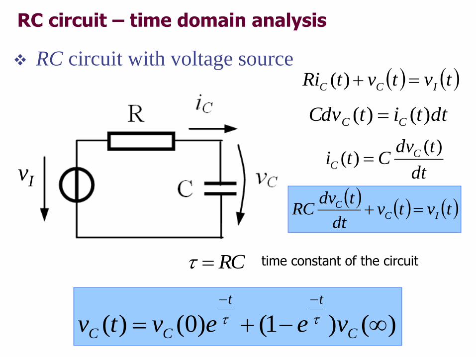
Defining relation between current and voltage
dttitCdv CC )()(
Considering finite variations:
tivC CC
Nonsinusoidal signal generators are based on charging and
discharging a capacitor; the voltage across the capacitor is further
compared with two thresholds using a hysteresis comparator
time constant of the circuit
)()1()0()(
C
tt
CC veevtv
dttitCdv CC )()(
tvtvtRi ICC )(
tvtv
dt
tdvRC IC
C
dt
tdvCti C
C
)()(
RC
vI
RC circuit – time domain analysis
RC circuit with voltage source
RC circuit – time domain analysis
RC circuit with dc voltage source
)()1()0()(
C
tt
CC veevtv
RCVvv ICC ;)(;0)0(
)0(Cv
)(tvC)(Cv
Astable multivibrators (Relaxation oscillators)
Operating principle
• if the voltage across the
capacitor is fed to a PF
comparator, a rectangular
wave is obtained
• the time variation of the
voltage across the capacitor
is exponential type
)(1)0()(
C
tt
CC veevtv
OHOHThH
OLOLThL
rVVRR
RV
rVVRR
RV
21
1
21
1
1. Astable multivibrator-rectangular signal generator
tvtvRR
Rvvtv COD
21
1)(
vD
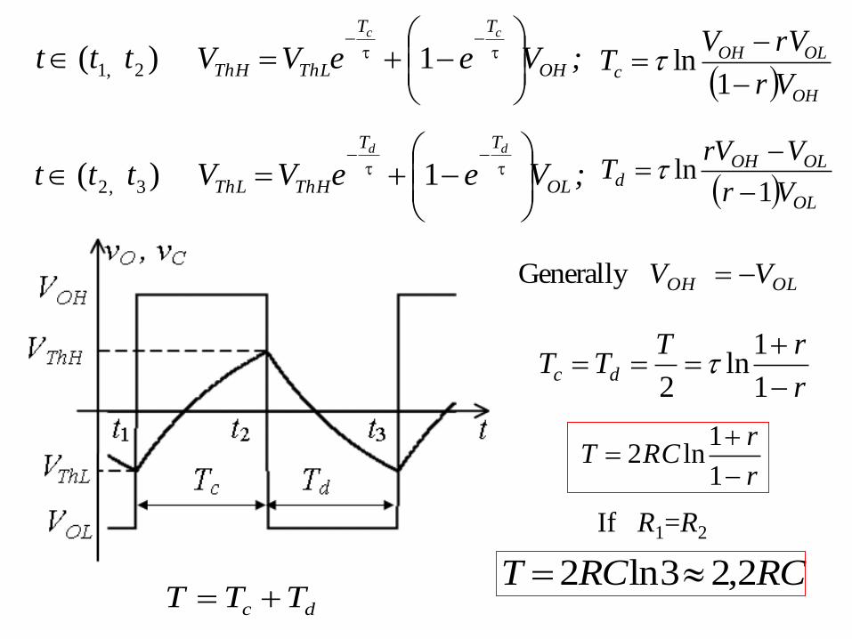
OLOH V V Generally
r
rTTT dc
1
1ln
2
r
rRCT
1
1ln2
If R1=R2
RCRCT 2,23ln2
;VeeVV OH
TT
ThLThH
cc
1 OH
OLOHc
Vr
rVVT
1ln
;VeeVV OL
TT
ThHThL
dd
1 OL
OLOHd
Vr
VrVT
1ln
)( 2,1 ttt
)( 3,2 ttt
dc TTT
Problem
±VPS = ±12V, R1=10kΩ, R2=20kΩ,
R=7.5kΩ and C=10nF. The op amp is
a rail-to-rail type.
a) What are the minimum and
maximum values for the voltage
across the capacitor?
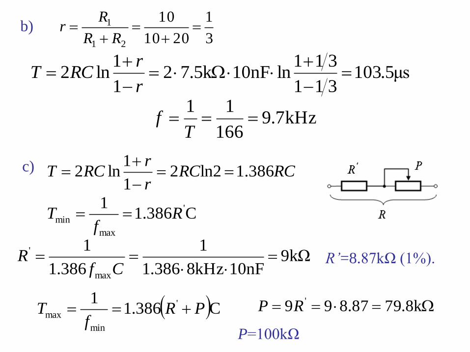
b) What is the frequency of the
rectangular signal?
c) Modify the circuit for an adjustable
frequency between fmin=0.8kHz and
fmax=8kHz?
V4122010
10
V4122010
10
21
1
21
1
OHThH
OLThL
VRR
RV
VRR
RV
a)
3
1
2010
10
21
1
RR
Rrb)
μs5.103311
311ln10nFk5.72
1
1ln2
r
rRCT
kHz7.9166
11
Tf
c)
C386.11 '
max
min Rf
T
kΩ910nFkHz8386.1
1
386.1
1
max
'
Cf
R R’=8.87kΩ (1%).
C386.11 '
min
max PRf
T k8.7987.899 'RP
P=100kΩ
RCRCr
rRCT 1.386ln22
1
1ln2
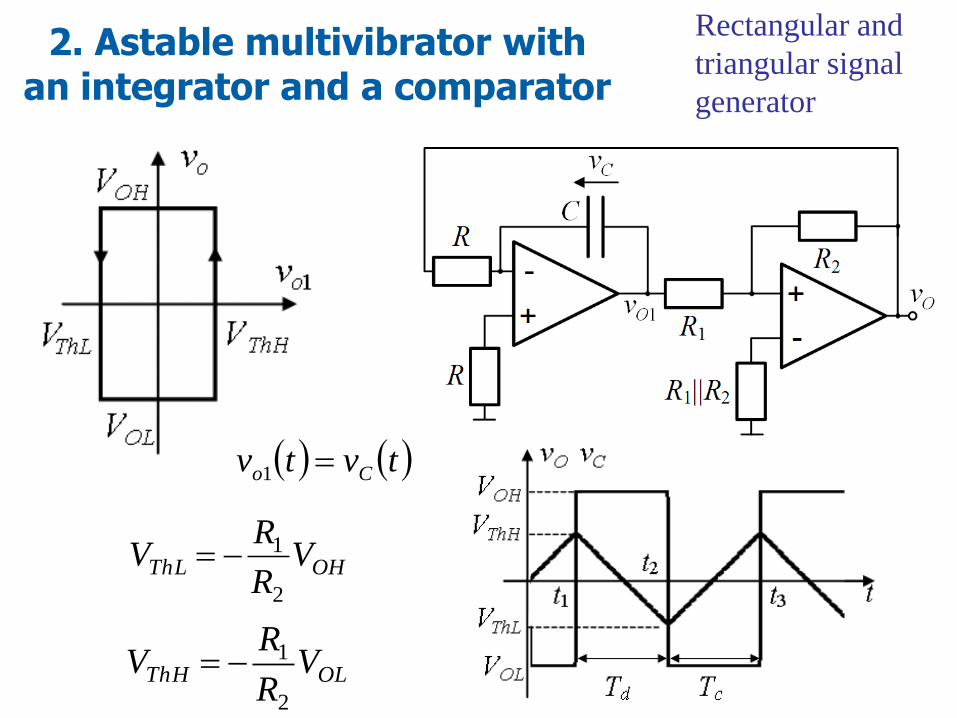
2. Astable multivibrator with an integrator and a comparator
OLThH VR
RV
2
1
OHThL VR
RV
2
1
Rectangular and
triangular signal
generator
tvtv Co 1
tivC CC
R
V
R
Vi OHOHC
0
d
ThHThLC
Tttt
VVv
12
;
OH
ThLThHd
V
VVRCT
OL
ThLThHc
V
VVRCT
cd TTT
OLOH VV generalIn
2
142R
RRC
V
VVRCT
OH
ThLThH
21If RR RC
fRCT4
14
discharge
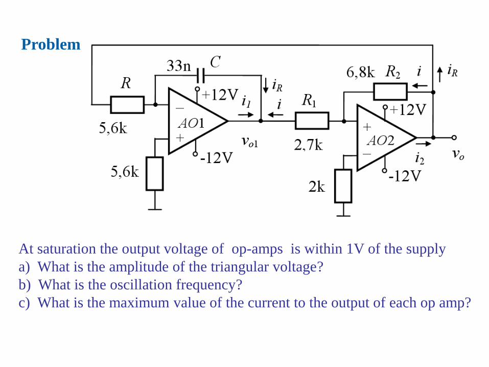
Problem
At saturation the output voltage of op-amps is within 1V of the supply
a) What is the amplitude of the triangular voltage?
b) What is the oscillation frequency?
c) What is the maximum value of the current to the output of each op amp?
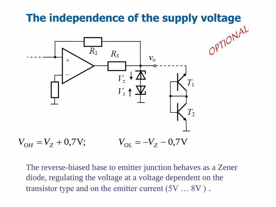
The independence of the supply voltage
V7,0V;7,0 ZOLZOH VVVV
The reverse-biased base to emitter junction behaves as a Zener
diode, regulating the voltage at a voltage dependent on the
transistor type and on the emitter current (5V … 8V ) .
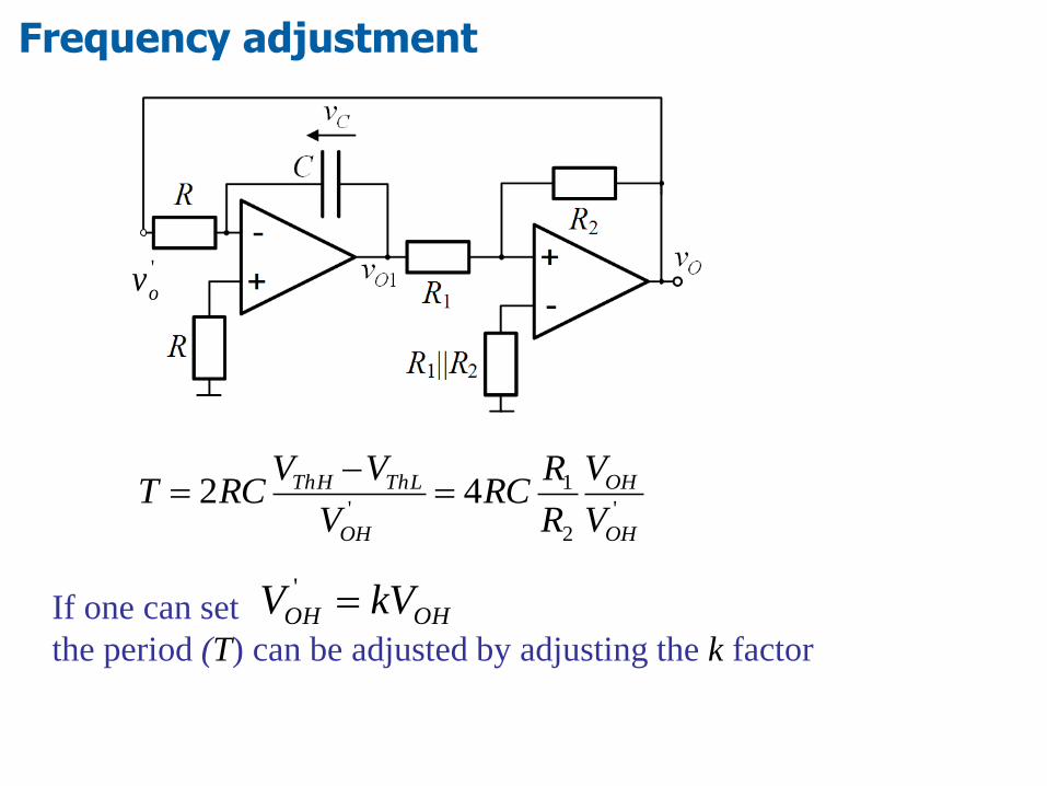
'
2
1
'42
OH
OH
OH
ThLThH
V
V
R
RRC
V
VVRCT
If one can set
the period (T) can be adjusted by adjusting the k factorOHOH kVV '
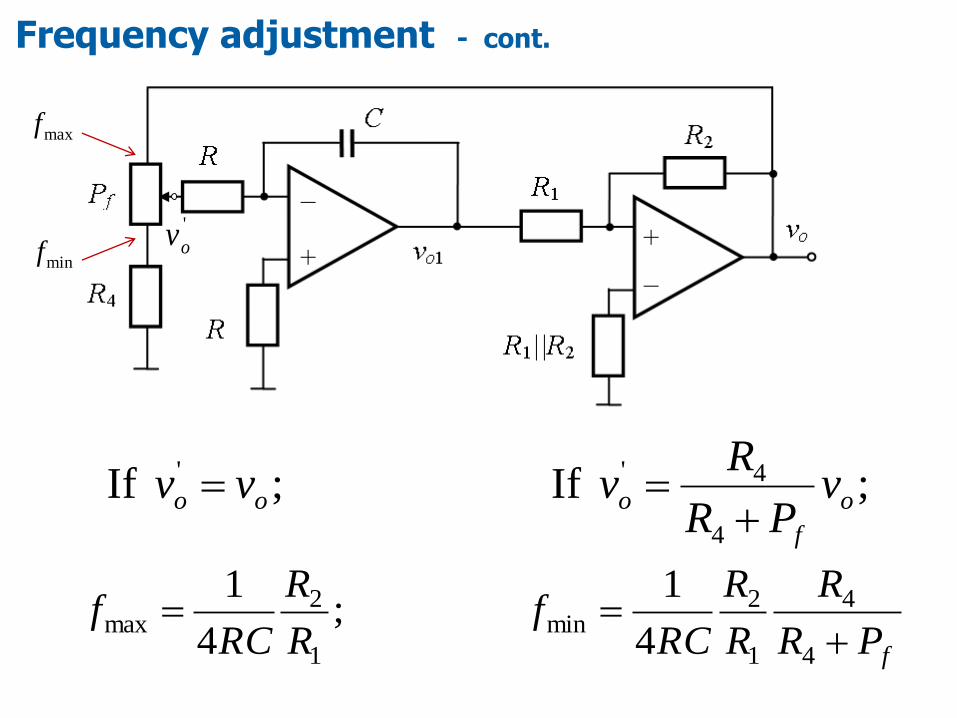
Frequency adjustment
'
ov
fPR
R
R
R
RCf
R
R
RCf
4
4
1
2min
1
2max
4
1;
4
1
Frequency adjustment - cont.
;If;If4
4''
o
f
ooo vPR
Rvvv
'
ov
maxf
minf
OHaThL VR
RV
R
RV
2
1
2
11
OLaThH V
R
RV
R
RV
2
1
2
11
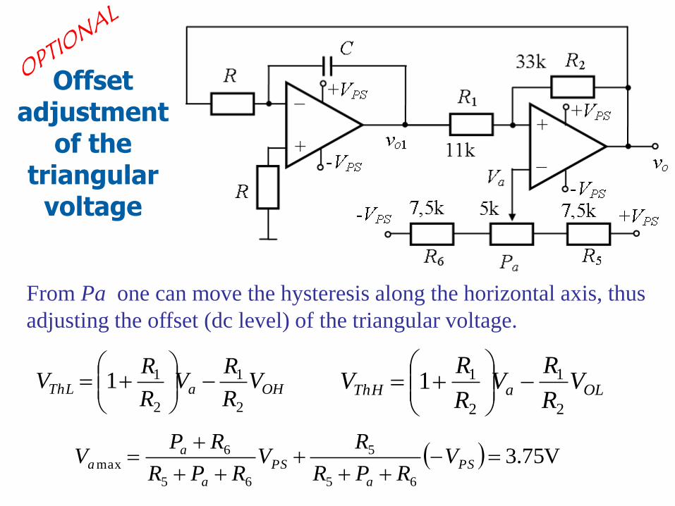
Offset adjustment
of the triangular
voltage
V75.365
5
65
6max
PS
a
PS
a
aa V
RPR
RV
RPR
RPV
From Pa one can move the hysteresis along the horizontal axis, thus
adjusting the offset (dc level) of the triangular voltage.
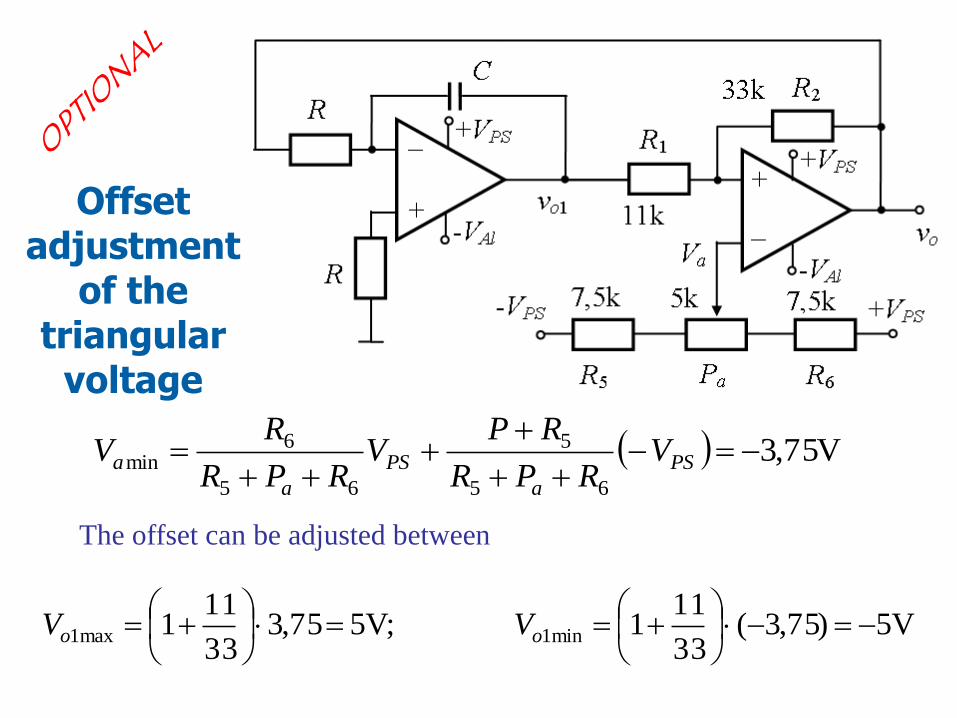
V75,365
5
65
6min
PS
a
PS
a
a VRPR
RPV
RPR
RV
The offset can be adjusted between
V5)75,3(33
111V;575,3
33
111 min1max1
oo VV
Offset adjustment
of the triangular
voltage
Specialized integrated circuits for signals generation