NORME INTERNATIONALE CEI IEC INTERNATIONAL STANDARD 60848 Deuxième édition Second edition 2002-02 Langage de spécification GRAFCET pour diagrammes fonctionnels en séquence GRAFCET specification language for sequential function charts Numéro de référence Reference number CEI/IEC 60848:2002
Transcript
NORMEINTERNATIONALE
CEIIEC
INTERNATIONALSTANDARD
60848Deuxième édition
Second edition2002-02
Langage de spécification GRAFCETpour diagrammes fonctionnels en séquence
GRAFCET specification languagefor sequential function charts
Numéro de référenceReference number
CEI/IEC 60848:2002
Numérotation des publications
Depuis le 1er janvier 1997, les publications de la CEIsont numérotées à partir de 60000. Ainsi, la CEI 34-1devient la CEI 60034-1.
Editions consolidées
Les versions consolidées de certaines publications de laCEI incorporant les amendements sont disponibles. Parexemple, les numéros d�édition 1.0, 1.1 et 1.2 indiquentrespectivement la publication de base, la publication debase incorporant l�amendement 1, et la publication debase incorporant les amendements 1 et 2.
Informations supplémentairessur les publications de la CEI
Le contenu technique des publications de la CEI estconstamment revu par la CEI afin qu'il reflète l'étatactuel de la technique. Des renseignements relatifs àcette publication, y compris sa validité, sont dispo-nibles dans le Catalogue des publications de la CEI(voir ci-dessous) en plus des nouvelles éditions,amendements et corrigenda. Des informations sur lessujets à l�étude et l�avancement des travaux entreprispar le comité d�études qui a élaboré cette publication,ainsi que la liste des publications parues, sontégalement disponibles par l�intermédiaire de:
• Site web de la CEI (www.iec.ch)
• Catalogue des publications de la CEI
Le catalogue en ligne sur le site web de la CEI(www.iec.ch/catlg-f.htm) vous permet de faire desrecherches en utilisant de nombreux critères,comprenant des recherches textuelles, par comitéd�études ou date de publication. Des informationsen ligne sont également disponibles sur lesnouvelles publications, les publications rempla-cées ou retirées, ainsi que sur les corrigenda.
• IEC Just PublishedCe résumé des dernières publications parues(www.iec.ch/JP.htm) est aussi disponible parcourrier électronique. Veuillez prendre contactavec le Service client (voir ci-dessous) pour plusd�informations.
• Service clientsSi vous avez des questions au sujet de cettepublication ou avez besoin de renseignementssupplémentaires, prenez contact avec le Serviceclients:
As from 1 January 1997 all IEC publications areissued with a designation in the 60000 series. Forexample, IEC 34-1 is now referred to as IEC 60034-1.
Consolidated editions
The IEC is now publishing consolidated versions of itspublications. For example, edition numbers 1.0, 1.1and 1.2 refer, respectively, to the base publication,the base publication incorporating amendment 1 andthe base publication incorporating amendments 1and 2.
Further information on IEC publications
The technical content of IEC publications is keptunder constant review by the IEC, thus ensuring thatthe content reflects current technology. Informationrelating to this publication, including its validity, isavailable in the IEC Catalogue of publications(see below) in addition to new editions, amendmentsand corrigenda. Information on the subjects underconsideration and work in progress undertaken by thetechnical committee which has prepared thispublication, as well as the list of publications issued,is also available from the following:
• IEC Web Site (www.iec.ch)
• Catalogue of IEC publications
The on-line catalogue on the IEC web site(www.iec.ch/catlg-e.htm) enables you to searchby a variety of criteria including text searches,technical committees and date of publication. On-line information is also available on recentlyissued publications, withdrawn and replacedpublications, as well as corrigenda.
• IEC Just Published
This summary of recently issued publications(www.iec.ch/JP.htm) is also available by email.Please contact the Customer Service Centre (seebelow) for further information.
• Customer Service CentreIf you have any questions regarding thispublication or need further assistance, pleasecontact the Customer Service Centre:
Langage de spécification GRAFCETpour diagrammes fonctionnels en séquence
GRAFCET specification languagefor sequential function charts
Pour prix, voir catalogue en vigueurFor price, see current catalogue
IEC 2002 Droits de reproduction réservés Copyright - all rights reserved
Aucune partie de cette publication ne peut être reproduite niutilisée sous quelque forme que ce soit et par aucun procédé,électronique ou mécanique, y compris la photocopie et lesmicrofilms, sans l'accord écrit de l'éditeur.
No part of this publication may be reproduced or utilized in anyform or by any means, electronic or mechanical, includingphotocopying and microfilm, without permission in writing fromthe publisher.
International Electrotechnical Commission, 3, rue de Varembé, PO Box 131, CH-1211 Geneva 20, SwitzerlandTelephone: +41 22 919 02 11 Telefax: +41 22 919 03 00 E-mail: [email protected] Web: www.iec.ch
CODE PRIXPRICE CODE XACommission Electrotechnique Internationale
International Electrotechnical CommissionМеждународная Электротехническая Комиссия
1 Domaine d’application et objet ..........................................................................................82 Références normatives .....................................................................................................83 Termes et définitions ........................................................................................................84 Principes généraux ......................................................................................................... 12
4.1 Contexte................................................................................................................ 124.2 Le GRAFCET, un langage de spécification comportementale ................................. 144.3 GRAFCET, présentation sommaire ........................................................................ 144.4 Règle de syntaxe ................................................................................................... 184.5 Règles d'évolution ................................................................................................. 184.6 Evénements d’entrée ............................................................................................. 204.7 Evénements internes ............................................................................................. 204.8 Modes de sortie ..................................................................................................... 224.9 Application des règles d’évolution .......................................................................... 224.10 Comparaison entre les deux modes de sortie ......................................................... 28
5 Représentation graphique des éléments.......................................................................... 306 Représentation graphique des structures de séquences .................................................. 56
6.1 Structures de base ................................................................................................ 566.2 Structures particulières .......................................................................................... 62
7 Structuration ................................................................................................................... 687.1 Partition d’un grafcet.............................................................................................. 687.2 Structuration par forçage d'un grafcet partiel ......................................................... 727.3 Structuration par encapsulation.............................................................................. 747.4 Structuration par macro-étapes .............................................................................. 80
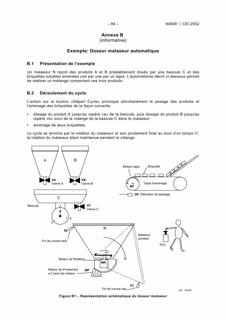
Annexe A (informative) Exemple de commande d’une presse ............................................... 82Annexe B (informative) Exemple: Doseur malaxeur automatique........................................... 84Annexe C (informative) Les relations entre le GRAFCET selon la CEI 60848 et le SFCselon la CEI 61131-3............................................................................................................. 96
1 Scope and object ..............................................................................................................92 Normative references........................................................................................................93 Terms and definitions .......................................................................................................94 General principles........................................................................................................... 13
4.1 Context.................................................................................................................. 134.2 GRAFCET, a behaviour specification language ...................................................... 154.3 GRAFCET, short presentation................................................................................ 154.4 Syntax rule ............................................................................................................ 194.5 Evolution rules ....................................................................................................... 194.6 Input events........................................................................................................... 214.7 Internal events....................................................................................................... 214.8 Output modes ........................................................................................................ 234.9 Application of the evolution rules............................................................................ 234.10 Comparison between the two output modes ........................................................... 29
5 Graphical representation of the elements ........................................................................ 316 Graphical representation of sequential structures ............................................................ 57
7 Structuring...................................................................................................................... 697.1 Partition of a grafcet .............................................................................................. 697.2 Structuring using the forcing of a partial grafcet ..................................................... 737.3 Structuring using the enclosure .............................................................................. 757.4 Structuring using the macro-steps.......................................................................... 81
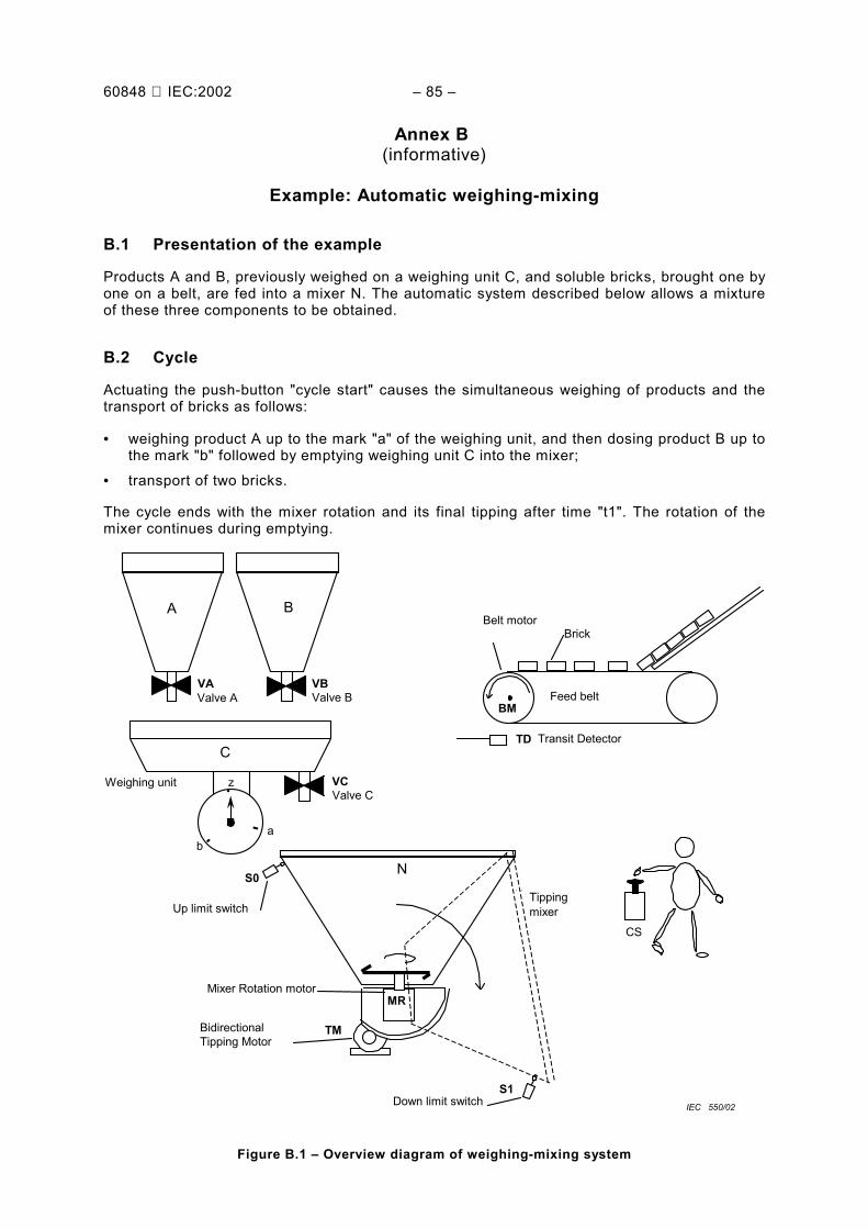
Annex A (informative) Example of control of a press ............................................................. 83Annex B (informative) Example: Automatic weighing-mixing.................................................. 85Annex C (informative) Relations between the GRAFCET of IEC 60848and the SFC of IEC 61131-3.................................................................................................. 97
LANGAGE DE SPÉCIFICATION GRAFCETPOUR DIAGRAMMES FONCTIONNELS EN SÉQUENCE
AVANT-PROPOS1) La CEI (Commission Électrotechnique Internationale) est une organisation mondiale de normalisation composée
de l'ensemble des comités électrotechniques nationaux (Comités nationaux de la CEI). La CEI a pour objet defavoriser la coopération internationale pour toutes les questions de normalisation dans les domaines del'électricité et de l'électronique. A cet effet, la CEI, entre autres activités, publie des Normes internationales.Leur élaboration est confiée à des comités d'études, aux travaux desquels tout Comité national intéressé par lesujet traité peut participer. Les organisations internationales, gouvernementales et non gouvernementales, enliaison avec la CEI, participent également aux travaux. La CEI collabore étroitement avec l'OrganisationInternationale de Normalisation (ISO), selon des conditions fixées par accord entre les deux organisations.
2) Les décisions ou accords officiels de la CEI concernant les questions techniques représentent, dans la mesuredu possible un accord international sur les sujets étudiés, étant donné que les Comités nationaux intéresséssont représentés dans chaque comité d’études.
3) Les documents produits se présentent sous la forme de recommandations internationales. Ils sont publiéscomme normes, spécifications techniques, rapports techniques ou guides et agréés comme tels par les Comitésnationaux.
4) Dans le but d'encourager l'unification internationale, les Comités nationaux de la CEI s'engagent à appliquer defaçon transparente, dans toute la mesure possible, les Normes internationales de la CEI dans leurs normesnationales et régionales. Toute divergence entre la norme de la CEI et la norme nationale ou régionalecorrespondante doit être indiquée en termes clairs dans cette dernière.
5) La CEI n’a fixé aucune procédure concernant le marquage comme indication d’approbation et sa responsabilitén’est pas engagée quand un matériel est déclaré conforme à l’une de ses normes.
6) L’attention est attirée sur le fait que certains des éléments de la présente Norme internationale peuvent fairel’objet de droits de propriété intellectuelle ou de droits analogues. La CEI ne saurait être tenue pourresponsable de ne pas avoir identifié de tels droits de propriété et de ne pas avoir signalé leur existence.
La Norme internationale CEI 60848 a été établie par le sous-comité 3B: Documentation, ducomité d'études 3 de la CEI: Structures d'informations, documentation et symboles graphiques.
Cette deuxième édition annule et remplace la première édition parue en 1988, dont elleconstitue une révision technique générale comprenant l’ajout des principaux concepts suivants:événement d’entrée, événement interne, assignation, affectation, forçage, macro-étape etencapsulation.
Le texte de cette norme est issu des documents suivants:
FDIS Rapport de vote
3B/344/FDIS 3B/346/RVD
Le rapport de vote indiqué dans le tableau ci-dessus donne toute information sur le vote ayantabouti à l'approbation de cette norme.
Cette publication a été rédigée selon les Directives ISO/CEI, Partie 3.
Les annexes A, B et C sont données uniquement à titre d’information.
Le comité a décidé que le contenu de cette publication ne sera pas modifié avant 2006. A cettedate, la publication sera• reconduite;• supprimée;• remplacée par une édition révisée, ou• amendée.
60848 IEC:2002 – 5 –
INTERNATIONAL ELECTROTECHNICAL COMMISSION____________
GRAFCET SPECIFICATION LANGUAGEFOR SEQUENTIAL FUNCTION CHARTS
FOREWORD1) The IEC (International Electrotechnical Commission) is a worldwide organization for standardization comprising
all national electrotechnical committees (IEC National Committees). The object of the IEC is to promoteinternational co-operation on all questions concerning standardization in the electrical and electronic fields. Tothis end and in addition to other activities, the IEC publishes International Standards. Their preparation isentrusted to technical committees; any IEC National Committee interested in the subject dealt with mayparticipate in this preparatory work. International, governmental and non-governmental organizations liaisingwith the IEC also participate in this preparation. The IEC collaborates closely with the International Organizationfor Standardization (ISO) in accordance with conditions determined by agreement between the twoorganizations.
2) The formal decisions or agreements of the IEC on technical matters express, as nearly as possible, aninternational consensus of opinion on the relevant subjects since each technical committee has representationfrom all interested National Committees.
3) The documents produced have the form of recommendations for international use and are published in the formof standards, technical specifications, technical reports or guides and they are accepted by the NationalCommittees in that sense.
4) In order to promote international unification, IEC National Committees undertake to apply IEC InternationalStandards transparently to the maximum extent possible in their national and regional standards. Anydivergence between the IEC Standard and the corresponding national or regional standard shall be clearlyindicated in the latter.
5) The IEC provides no marking procedure to indicate its approval and can not be rendered responsible for anyequipment declared to be in conformity with one of its standards.
6) Attention is drawn to the possibility that some of the elements of this International Standard may be the subjectof patent rights. The IEC shall not be held responsible for identifying any or all such patent rights.
International Standard IEC 60848 has been prepared by subcommittee 3B: Documentation, ofIEC technical committee 3: Information structures, documentation and graphical symbols.
This second edition cancels and replaces the first edition published in 1988 and constitutes aglobal technical revision with the addition of the following main concepts: input event, internalevent, assignation, allocation, forcing, macro-step and enclosure.
The text of this standard is based on the following documents:
FDIS Report on voting
3B/344/FDIS 3B/346/RVD
Full information on the voting for the approval of this standard can be found in the report onvoting indicated in the above table.
This publication has been drafted in accordance with the ISO/IEC Directives, Part 3.
Annexes A, B and C are for information only.
The committee has decided that the contents of this publication will remain unchanged until2006. At this date, the publication will be
• reconfirmed;• withdrawn;• replaced by a revised edition, or• amended.
– 6 – 60848 CEI:2002
INTRODUCTION
La principale raison de la révision de la première édition de cette norme est la volonté desutilisateurs d'enrichir l'outil de spécification normalisé par de nouveaux concepts, permettantune description structurée et hiérarchisée.
Par ailleurs, il apparaît maintenant nécessaire d’ajouter aux aspects descriptifs et fonctionnelsde la première édition les aspects formels et comportementaux essentiels à la définition d’unvéritable langage de spécification.
Toutes ces raisons ont rendu nécessaire une révision générale de la norme.
Cette norme est destinée principalement aux utilisateurs (concepteurs, réalisateurs, agents demaintenance, etc.) qui ont besoin de spécifier le comportement d’un système (commanded’une machine automatique, composant de sûreté, etc.). Ce langage de spécification peutégalement servir de moyen de communication entre les concepteurs et les utilisateurs desystèmes automatisés.
60848 IEC:2002 – 7 –
INTRODUCTION
The main reason for the revision of this standard is the desire of the users to increase thestandardised specification language with new concepts, allowing a structured and hierarchicaldescription.
Otherwise, in addition to the descriptive and functional aspects of the first edition, it now seemsnecessary to add the formal and behavioural aspects, which are essential for the definition of areal specification language.
For all these reasons, an overall review of the document is required.
This standard is mainly for people (design engineers, realisation engineers, maintenanceengineers, etc.) who need to specify the behaviour of a system (control-command of anautomatic machine, safety component, etc.). This specification language should also serve asa communication means between designers and users of automated systems.
– 8 – 60848 CEI:2002
LANGAGE DE SPÉCIFICATION GRAFCETPOUR DIAGRAMMES FONCTIONNELS EN SÉQUENCE
1 Domaine d’application et objet
La présente Norme internationale définit le langage de spécification GRAFCET 1) pour la des-cription fonctionnelle du comportement de la partie séquentielle des systèmes de commande.
Cette norme définit les symboles et les règles nécessaires à la représentation graphique de celangage, ainsi que l'interprétation qui en est faite.
Cette norme a été établie pour les systèmes automatisés de production des applicationsindustrielles, cependant aucun champ d'application n'est exclu.
Les méthodes de réalisation d’une spécification utilisant le GRAFCET ne font pas partie dudomaine d’application de cette norme. Une méthode possible est l’utilisation du langage «SFC»décrit dans la CEI 61131-3, qui définit un ensemble de langages de programmation destinésaux automates programmables.
NOTE Voir l'annexe C pour de plus amples informations sur les relations entre la CEI 60848 et les langages deréalisation comme le SFC de la CEI 61131-3.
2 Références normatives
Les documents normatifs suivants contiennent des dispositions qui, par suite de la référencequi y est faite, constituent des dispositions valables pour la présente Norme internationale.Pour les références datées, les amendements ultérieurs ou les révisions de ces publications nes’appliquent pas. Toutefois, les parties prenantes aux accords fondés sur la présente Normeinternationale sont invitées à rechercher la possibilité d'appliquer les éditions les plus récentesdes documents normatifs indiqués ci-après. Pour les références non datées, la dernière éditiondu document normatif en référence s’applique. Les membres de la CEI et de l'ISO possèdentle registre des Normes internationales en vigueur.
CEI 60050-351:1998, Vocabulaire Electrotechnique International (VEI) – Partie 351:Commande et régulation automatiques
CEI 60617-12:1997, Symboles graphiques pour schémas – Partie 12: Opérateurs logiquesbinaires
3 Termes et définitions
Pour les besoins de la présente Norme internationale, les termes et définitions suivantss’appliquent. Les définitions des termes précédés d’un astérisque ne s’appliquent que dans lecontexte du langage de spécification GRAFCET.
3.1* actionélément du langage GRAFCET associé à une étape, l’action indique le comportement d’unevariable de sortie
———————1) GRAFCET, GRAphe Fonctionnel de Commande Etape Transition.
60848 IEC:2002 – 9 –
GRAFCET SPECIFICATION LANGUAGEFOR SEQUENTIAL FUNCTION CHARTS
1 Scope and object
This International Standard defines the GRAFCET1) specification language for the functionaldescription of the behaviour of the sequential part of a control system.
This standard specifies the symbols and the rules for the graphical representation of thislanguage, as well as for its interpretation.
This standard has been prepared for automated production systems of industrial applications.However no particular area of application is excluded.
Methods of development of a specification that makes use of GRAFCET are beyond the scopeof this standard. One method is for example the "SFC language" specified in IEC 61131-3,which defines a set of programming languages for programmable controllers.
NOTE See annex C for further information on the relations between IEC 60848 and implementation languagessuch as the SFC of IEC 61131-3.
2 Normative references
The following normative documents contain provisions, which, through reference in this text,constitute provisions of this International Standard. For dated references, subsequentamendments to, or revisions of, any of these publications do not apply. However, parties toagreements based on this International Standard are encouraged to investigate the possibilityof applying the most recent editions of the normative documents indicated below. For undatedreferences, the latest edition of the normative document referred to applies. Members of IECand ISO maintain registers of currently valid International Standards.
IEC 60050-351:1998, International Electrotechnical Vocabulary (VEI – Part 351: Automaticcontrol
IEC 60617-12:1997, Graphical symbols for diagrams – Part 12: Binary logical elements
3 Terms and definitions
For the purposes of this International Standard, the following definitions apply. The definitionsof the terms preceded by an asterisk apply only in the context of the GRAFCET specificationlanguage. The chosen order is the alphabetic one.
3.1* actionGRAFCET language element associated with a step, indicating an activity to be performed onoutput variables
———————1) GRAFCET , GRAphe Fonctionnel de Commande Etape Transition.
– 10 – 60848 CEI:2002
3.2diagrammereprésentation graphique décrivant le comportement d’un système, par exemple les relationsentre deux ou plus de deux grandeurs variables, actions ou états
3.3* liaison orientéeélément du langage GRAFCET, les liaisons orientées indiquent les voies d'évolution en reliantles étapes aux transitions et les transitions aux étapes
3.4* diagramme grafcetdiagramme fonctionnel utilisant le langage GRAFCETNOTE Le terme «diagramme grafcet» est, en raccourci, remplacé par «grafcet».
3.5* événement d’entréeévénement caractérisé par le changement de valeur d’une ou plusieurs variables d’entrée de lapartie séquentielle du système
3.6* événement interneévénement caractérisé par un événement d’entrée associé à la situation de la partieséquentielle du système
3.7* interprétationpartie du GRAFCET permettant de faire la relation entre:– les variables d'entrées et la structure, par les réceptivités;– les variables de sorties et la structure, par les actions
3.8* situationdésignation de l'état du système spécifié par un grafcet et caractérisé par les étapes actives àl’instant considéré
3.9* étapeélément du langage GRAFCET utilisé pour définir la situation de la partie séquentielle d’unsystèmeNOTE 1 Une étape est soit active soit inactive.
NOTE 2 L’ensemble des étapes actives représente la situation du système.
3.10* structurepartie du GRAFCET permettant de décrire l'évolution possible entre les situations
3.11systèmeensemble d'éléments reliés entre eux, considérés dans un contexte défini comme un tout etséparés de leur environnement[VEI 351-11-01]NOTE 1 Les éléments du système peuvent être à la fois des objets matériels ou des concepts aussi bienque les résultats de ceux-ci (par exemple formes d'organisation, méthodes mathématiques, langages deprogrammation).
60848 IEC:2002 – 11 –
3.2chart, graphgraphical presentation describing the behaviour of a system, for example the relations betweentwo or more variable quantities, operations or states
3.3* directed linkGRAFCET language element indicating the evolution paths between steps by connecting stepsto transitions and transitions to steps
3.4* grafcet chartfunction chart using GRAFCETNOTE The “grafcet chart” can, in short form, be called “grafcet”.
3.5* input eventevent characterized by the change of at least one value of all input variables of the sequentialpart of the system
3.6* internal eventevent characterized by an input event associated with the situation of the sequential part of thesystem
3.7* interpretationpart of the GRAFCET enabling the linkage of:– the input variables and the structure, by the means of the transition-condition;– the output variables and the structure, by the means of the actions
3.8* situationname of the state of the system described by grafcet and characterised by the active steps at agiven instant
3.9* stepGRAFCET language element used for the definition of the state of the sequential part of thesystemNOTE 1 A step can be active or inactive.
NOTE 2 The set of active steps represents the situation of the system.
3.10* structurepart of the GRAFCET enabling the description of the possible evolution between situations
3.11systema set of interrelated elements considered in a defined context as a whole and separated fromtheir environment[IEV 351-11-01]NOTE 1 Such elements may be material objects and concepts as well as their results (e.g. forms of organisation,mathematical methods, programming languages).
– 12 – 60848 CEI:2002
NOTE 2 Le système est considéré comme séparé de l’environnement et des autres systèmes extérieurs par unesurface imaginaire qui coupe les liaisons entre eux et le système.
NOTE 3 Le langage GRAFCET peut être utilisé pour décrire le comportement logique de n’importe quel type desystème.
3.12* évolution fugaceévolution caractérisée par le franchissement de plusieurs transitions successives àl’occurrence d’un unique événement d’entrée
3.13* transitionélément du langage GRAFCET, une transition indique la possibilité d'évolution d'activité entredeux ou plusieurs étapesNOTE Cette évolution possible s'accomplit par le franchissement de la transition.
3.14* réceptivitéélément du langage GRAFCET associé à une transition, la réceptivité exprime le résultat d’uneexpression booléenneNOTE Une réceptivité est soit vraie soit fausse.
4 Principes généraux
4.1 Contexte
La réalisation d'un système automatisé requiert, notamment, une description liant les effetsaux causes. Pour cela, on décrira l'aspect logique du comportement souhaité du système.
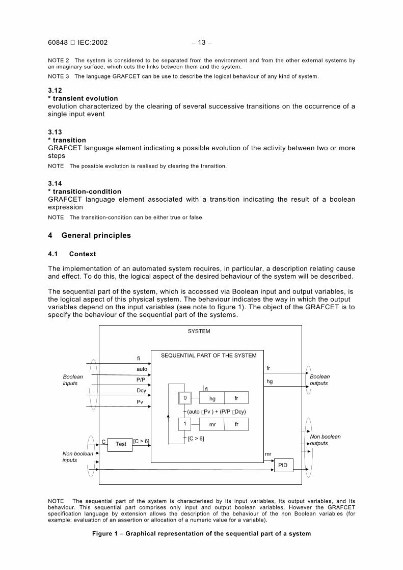
La partie séquentielle du système désigne l'aspect logique d'un système physique auquel onaccède par des variables d'entrée et des variables de sortie booléennes. Le comportementindique la manière dont les variables de sortie dépendent des variables d'entrée (voir note dela figure 1). Le GRAFCET a pour objet de spécifier le comportement de la partie séquentielledes systèmes.
[C > 6]
fi
SYSTEME
PARTIE SEQUENTIELLE DU SYSTEME
[C > 6]
(auto ⋅ Pv ) + (P/P ⋅ Dcy)
0
1
PID
C TestSorties nonbooléennes
Entréesbooléennes
Entrées nonbooléennes
mr fr
frhg
mr
hg
fr
Dcy
P/P
auto
fi
Sortiesbooléennes
Pv
NOTE La partie séquentielle du système est caractérisée par ses variables d'entrée, ses variables de sortie et soncomportement. Cette partie séquentielle ne comporte que des variables d'entrées et de sorties booléennes,toutefois le langage de spécification GRAFCET permet par extension (exemple: évaluation d'un prédicat ouaffectation d'une valeur numérique à une variable) de décrire le comportement de variables non booléennes.
Figure 1 – Représentation graphique de la partie séquentielle d’un système
60848 IEC:2002 – 13 –
NOTE 2 The system is considered to be separated from the environment and from the other external systems byan imaginary surface, which cuts the links between them and the system.
NOTE 3 The language GRAFCET can be use to describe the logical behaviour of any kind of system.
3.12* transient evolutionevolution characterized by the clearing of several successive transitions on the occurrence of asingle input event
3.13* transitionGRAFCET language element indicating a possible evolution of the activity between two or morestepsNOTE The possible evolution is realised by clearing the transition.
3.14* transition-conditionGRAFCET language element associated with a transition indicating the result of a booleanexpressionNOTE The transition-condition can be either true or false.
4 General principles
4.1 Context
The implementation of an automated system requires, in particular, a description relating causeand effect. To do this, the logical aspect of the desired behaviour of the system will be described.
The sequential part of the system, which is accessed via Boolean input and output variables, isthe logical aspect of this physical system. The behaviour indicates the way in which the outputvariables depend on the input variables (see note to figure 1). The object of the GRAFCET is tospecify the behaviour of the sequential part of the systems.
[C > 6]
fi
SYSTEM
SEQUENTIAL PART OF THE SYSTEM
[C > 6]
(auto ⋅ Pv ) + (P/P ⋅ Dcy)
0
1
C Test
Booleaninputs
Non booleaninputs
mr fr
frhg
hg
fr
Dcy
P/P
auto
fi
Booleanoutputs
Pv
PID
mr
Non booleanoutputs
NOTE The sequential part of the system is characterised by its input variables, its output variables, and itsbehaviour. This sequential part comprises only input and output boolean variables. However the GRAFCETspecification language by extension allows the description of the behaviour of the non Boolean variables (forexample: evaluation of an assertion or allocation of a numeric value for a variable).
Figure 1 – Graphical representation of the sequential part of a system
– 14 – 60848 CEI:2002
4.2 Le GRAFCET, un langage de spécification comportementale
Le langage de spécification GRAFCET permet d'établir un grafcet exprimant le comportementattendu de la partie séquentielle d’un système déterminé. Ce langage se caractériseprincipalement par ses éléments graphiques qui, associés à une expression alphanumériquedes variables, offre une représentation synthétique du comportement reposant sur unedescription indirecte de la situation du système.
La description du comportement sous forme d’états est la suivante: les états, «monomarqués»,correspondent aux situations du GRAFCET, ce qui implique l’unicité de la situation à un instantdonné. Les états sont reliés les uns aux autres par des arcs assortis d'une conditiond'évolution, ce qui permet de décrire le passage d'une situation à une autre.
Pour des raisons de commodité, la description du comportement sous forme d'états estavantageusement remplacée par une description sous forme d'étapes appelée GRAFCET.Dans le GRAFCET plusieurs étapes peuvent être actives simultanément, la situation étantalors caractérisée par l'ensemble des étapes actives à l'instant considéré. Les conditionsd'évolution d'un ensemble d'étapes vers un autre sont alors portées par une ou plusieurstransitions, caractérisées chacune par:
• ses étapes amont,
• ses étapes aval,
• sa réceptivité associée.
NOTE La règle de syntaxe imposant l'alternance étape-transition résulte de ce qui précède.
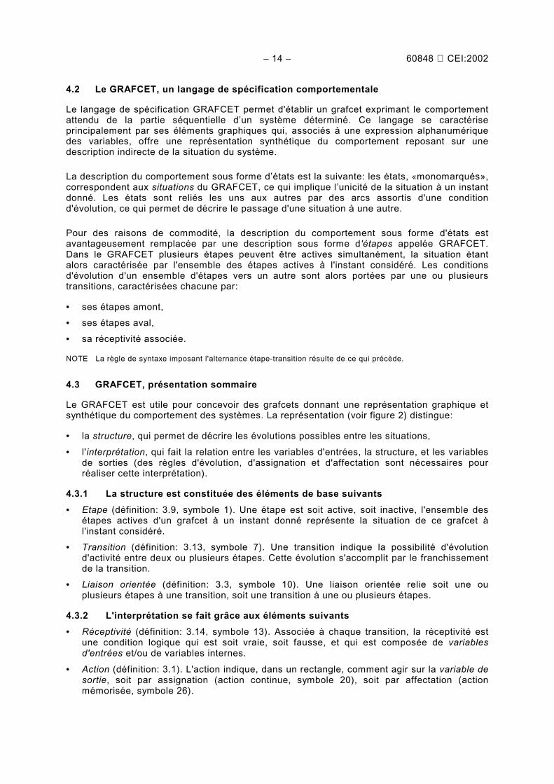
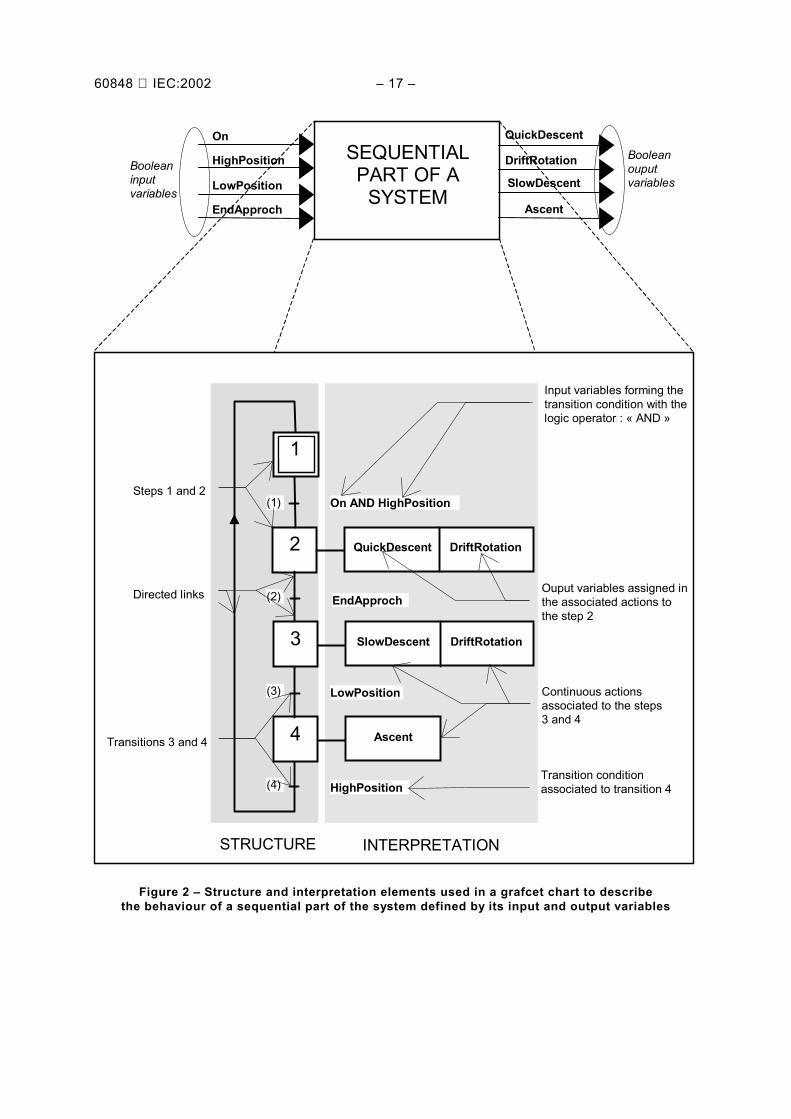
4.3 GRAFCET, présentation sommaire
Le GRAFCET est utile pour concevoir des grafcets donnant une représentation graphique etsynthétique du comportement des systèmes. La représentation (voir figure 2) distingue:
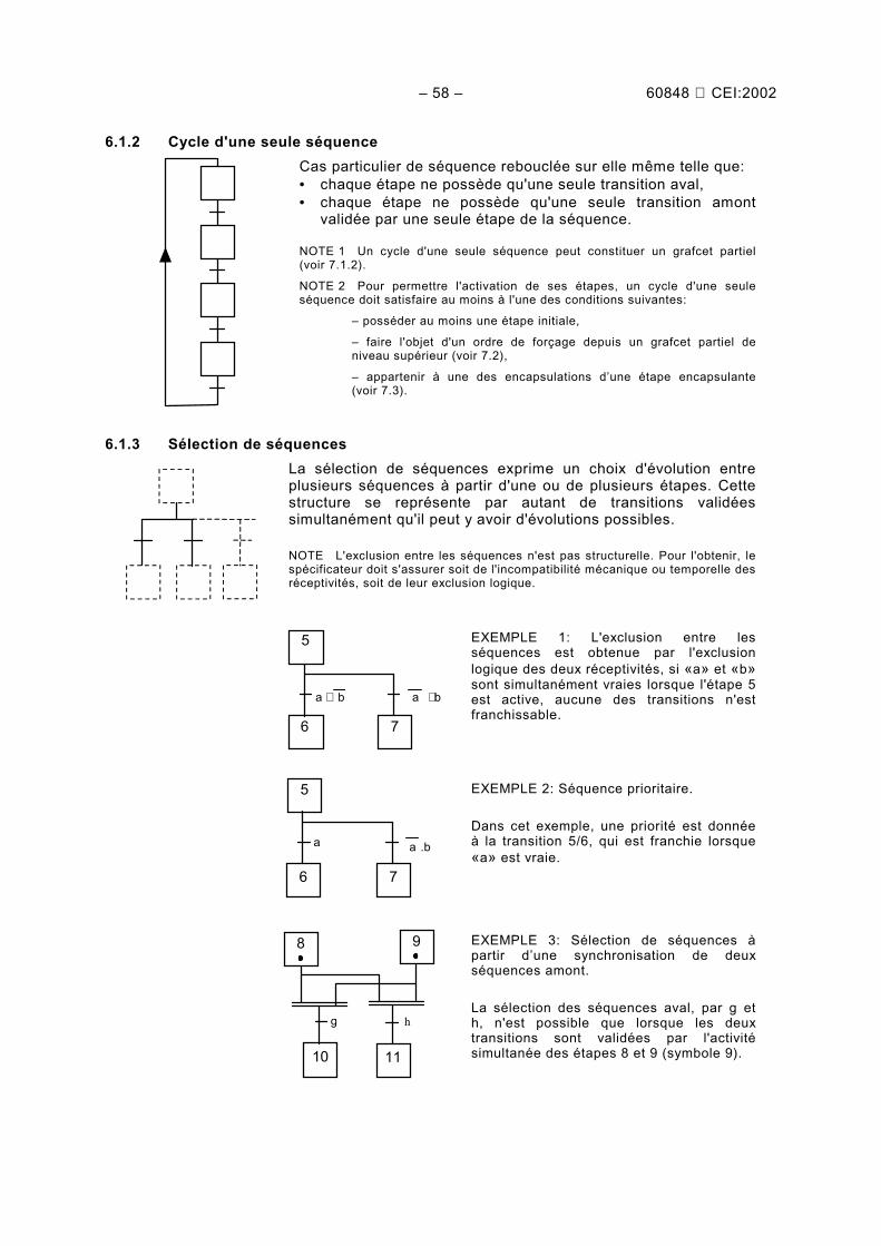
• la structure, qui permet de décrire les évolutions possibles entre les situations,
• l'interprétation, qui fait la relation entre les variables d'entrées, la structure, et les variablesde sorties (des règles d'évolution, d'assignation et d'affectation sont nécessaires pourréaliser cette interprétation).
4.3.1 La structure est constituée des éléments de base suivants• Etape (définition: 3.9, symbole 1). Une étape est soit active, soit inactive, l'ensemble des
étapes actives d'un grafcet à un instant donné représente la situation de ce grafcet àl'instant considéré.
• Transition (définition: 3.13, symbole 7). Une transition indique la possibilité d'évolutiond'activité entre deux ou plusieurs étapes. Cette évolution s'accomplit par le franchissementde la transition.
• Liaison orientée (définition: 3.3, symbole 10). Une liaison orientée relie soit une ouplusieurs étapes à une transition, soit une transition à une ou plusieurs étapes.
4.3.2 L'interprétation se fait grâce aux éléments suivants• Réceptivité (définition: 3.14, symbole 13). Associée à chaque transition, la réceptivité est
une condition logique qui est soit vraie, soit fausse, et qui est composée de variablesd'entrées et/ou de variables internes.
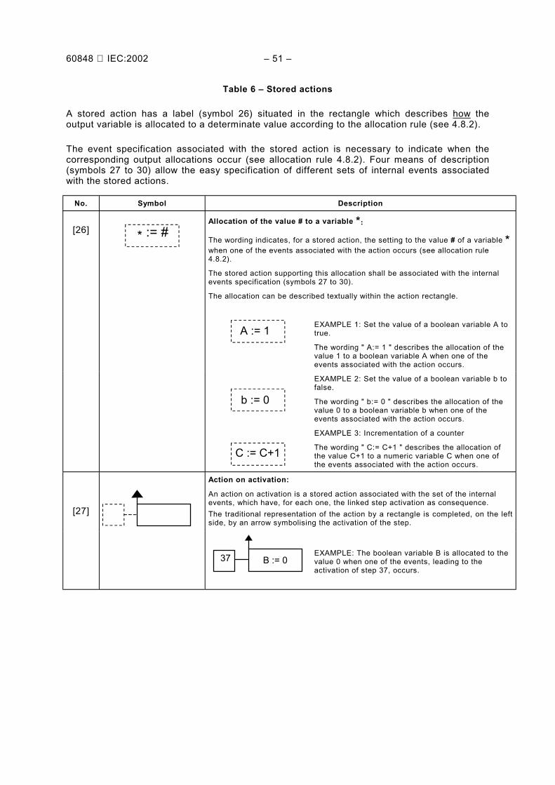
• Action (définition: 3.1). L'action indique, dans un rectangle, comment agir sur la variable desortie, soit par assignation (action continue, symbole 20), soit par affectation (actionmémorisée, symbole 26).
60848 IEC:2002 – 15 –
4.2 GRAFCET, a behaviour specification language
The GRAFCET specification language enables a grafcet to be created showing the expectedbehaviour of a given sequential system. This language is characterized mainly by its graphicelements, which, associated with an alphanumerical expression of variables, provides asynthetic representation of the behaviour, based on an indirect description of the situation ofthe system.
The behaviour description on states is the following: the "monomarked" states correspond tothe GRAFCET situations, which implies the uniqueness of the situation at a given instant. Thestates are connected to each other by means of an evolution condition, which allows thepassage from one situation to another one to be described.
For reasons of convenience, the behaviour description based on states is better replaced by adescription based on steps called GRAFCET. In the GRAFCET, several steps may be activesimultaneously, the situation being then characterized by the set of active steps at theconsidered moment. The evolution of one set of steps to another are translated by one orseveral transitions, each characterized by:
• its preceding steps,
• its succeeding steps,
• its associated transition-condition.
NOTE These reasons lead to the syntax rule enforcing the alternation step-transition.
4.3 GRAFCET, short presentation
The GRAFCET is used for the design of grafcet charts to provide a graphical and syntheticrepresentation of the sequential systems behaviour. The representation (figure 2) distinguishes:
• the structure, which allows possible evolutions between the situations to be described,
• the interpretation, which enables the relationship between input, output variables and thestructure (evolution, assignation and allocation rules are necessary to achieve thisinterpretation).
4.3.1 The structure comprises the following basic items• Step (definition: 3.9, symbol 1). A step is either active or inactive, the set of the active
steps of a grafcet chart at any given instant represents the situation of this grafcet at thisinstant.
• Transition (definition: 3.13, symbol 7). A transition indicates that an evolution of the activitybetween two or more steps may evolve. This evolution is realized by the clearing of thetransition.
• Directed link (definition: 3.3, symbol 10). A directed link connects one or several steps to atransition, or a transition to one or several steps.
4.3.2 The following elements are used for the interpretation• Transition-condition (definition: 3.14, symbol 13). Associated with each transition, the
transition-condition is a logical expression which is true or false and which is composed ofinput variables and/or internal variables.
• Action (definition: 3.1). The action indicates, in a rectangle, what shall be done to theoutput variable, either by assignation (continuous action, symbol 20), or allocation (storedaction, symbol 26).
– 16 – 60848 CEI:2002
1
MarchePARTIE
SÉQUENTIELLEDU SYSTÈME
STRUCTURE INTERPRÉTATION
PositionHaute
PositionHaute
Marche ET PositionHaute
2
DescenteRapide
DescenteRapide
RotationBroche
RotationBroche
(4)
(3)
(2)
(1)
FinApproche
FinApproche
3
DescenteLente
DescenteLente RotationBroche
PositionBasse
PositionBasse
4
Montée
Montée
Réceptivité associée à latransition 4
Actions continuesassociées aux étapes3 et 4
Transitions 3 et 4
Etapes 1 et 2
Variables desortiebooléennes
Variablesd’entréebooléennes
Liaisonsorientées
Variables d’entrée formantla réceptivité avecl’opérateur logique « ET »
Variables de sortieassignées dans les actionsassociées à l’étape 2
Figure 2 – Eléments de structure et d'interprétation utilisés dans un grafcetpour décrire le comportement de la partie séquentielle d’un système
défini par ses variables d'entrée et de sortie
60848 IEC:2002 – 17 –
1
OnSEQUENTIALPART OF A
SYSTEM
STRUCTURE INTERPRETATION
HighPosition
HighPosition
On AND HighPosition
2
QuickDescent
QuickDescent
DriftRotation
DriftRotation
(4)
(3)
(2)
(1)
EndApproch
EndApproch
3
SlowDescent
SlowDescent DriftRotation
LowPosition
LowPosition
4
Ascent
Ascent
Input variables forming thetransition condition with thelogic operator : « AND »
Figure 2 – Structure and interpretation elements used in a grafcet chart to describethe behaviour of a sequential part of the system defined by its input and output variables
– 18 – 60848 CEI:2002
4.4 Règle de syntaxe
L'alternance étape-transition et transition-étape doit toujours être respectée, quelle que soit laséquence parcourue.
Conséquences:
• Deux étapes ou deux transitions ne doivent jamais être reliées par une liaison orientée.
• La liaison orientée relie obligatoirement une étape à une transition ou une transition à uneétape.
4.5 Règles d'évolution
Sachant que toute situation est caractérisée par l'ensemble des étapes actives à l'instantconsidéré, les règles d'évolution du GRAFCET ne sont que l'application, sur les étapes, duprincipe d'évolution entre les situations de la partie séquentielle du système.
4.5.1 Situation initiale
La situation initiale est la situation à l'instant initial, elle est donc décrite par l'ensemble desétapes actives à cet instant. Le choix de la situation à l'instant initial repose sur des consi-dérations méthodologiques et relatives à la nature de la partie séquentielle du système visé.
Règle 1: La situation initiale, choisie par le concepteur, est la situation à l'instant initial.
4.5.2 Franchissement d'une transition
Règle 2: Une transition est dite validée lorsque toutes les étapes immédiatement précédentesreliées à cette transition sont actives. Le franchissement d'une transition se produit:
• lorsque la transition est VALIDÉE,
• ET QUE la réceptivité associée à cette transition est VRAIE.
4.5.3 Evolution des étapes actives
Règle 3: Le franchissement d'une transition entraîne simultanément l'activation de toutes lesétapes immédiatement suivantes et la désactivation de toutes les étapes immédiatementprécédentes.
4.5.4 Evolutions simultanées
L'évolution entre deux situations actives implique qu'aucune situation intermédiaire ne soitpossible, on passe donc instantanément d'une représentation de la situation par un ensembled'étapes à une autre représentation.
Règle 4: Plusieurs transitions simultanément franchissables sont simultanément franchies.
4.5.5 Activation et désactivation simultanées d'une étape
Si une même étape participe à la description de la situation précédente et à celle de lasituation suivante, elle ne peut, en conséquence, que rester active.
Règle 5: Si, au cours du fonctionnement, une étape active est simultanément activée etdésactivée, alors elle reste active.
60848 IEC:2002 – 19 –
4.4 Syntax rule
Step transition and transition step alternation shall always be respected whatever the sequence.
Consequences:
• Two steps shall never be connected directly by a directed link.
• The directed link shall only connect a step to a transition or a transition to a step.
4.5 Evolution rules
As each situation is characterized by the set of active steps at a given instant, the GRAFCETevolution rules only affect the application, on the steps, of the evolution principle between thesituations of the sequential part of the system.
4.5.1 Initial situation
The initial situation is the situation at the initial time. Therefore it is described by the set ofsteps active at this time. The choice of the situation at the initial time depends on themethodology relating to the type of sequential part of the system considered.
Rule 1: The initial situation, chosen by the designer, is the situation at the initial time.
4.5.2 Clearing of a transition
Rule 2: A transition is said to be enabled when all immediately preceding steps linked to thistransition are active. The clearing of a transition occurs:
• when the transition is ENABLED,
• AND WHEN its associated transition-condition is TRUE.
4.5.3 Evolution of active steps
Rule 3: The clearing of a transition simultaneously provokes the activation of all the immediatesucceeding steps and the deactivation of all the immediate preceding steps.
4.5.4 Simultaneous evolutions
The evolution between two active situations implies that no other intermediate situation ispossible, the change from one representation of the situation by a set of steps to anotherrepresentation is instantaneous.
Rule 4: Several transitions, which can be cleared simultaneously, are simultaneously cleared.
4.5.5 Simultaneous activation and deactivation of a step
If a step is included in the description of the preceding situation and in that of the following one,it can therefore only remain active.
Rule 5: If during the operation, an active step is simultaneously activated and deactivated, itremains active.
– 20 – 60848 CEI:2002
4.6 Evénements d’entrée
Les règles d'évolution montrent que seul un changement des valeurs des variables d'entrée estsusceptible de provoquer l'évolution d'un grafcet. Ce changement, appelé "événementd'entrée" doit être défini par la valeur antérieure et la valeur postérieure de toutes les variablesd'entrées pour caractériser cet événement unique. Dans la pratique, on ne spécifie que desensembles d'événements d'entrée caractérisés par le changement d'état (front montant oufront descendant) d'une ou plusieurs variables booléennes d'entrée.
NOTE Le front montant d'une variable logique, qui se note par le signe «↑ » devant une variable booléenne,indique que ce front montant n'est vrai qu'au passage de la valeur 0 à la valeur 1 de la variable concernée. Le frontdescendant d'une variable logique, qui se note par le signe «↓ » devant une variable booléenne, indique que cefront descendant n'est vrai qu'au passage de la valeur 1 à la valeur 0 de la variable concernée.
On dit que «l'événement se produit» à la date du changement d'état des variables d'entrée quile caractérisent.
4.6.1 Spécification des événements d'entrée
La spécification des événements d'entrée se fait par une expression logique d'une ou plusieursvariables caractéristiques, souvent dans une réceptivité et plus rarement en vue de spécifierdirectement un événement interne (voir 4.7).
↑↑↑↑a
EXEMPLE 1L’expression «↑a» décrit l'ensemble de tous les événements d'entrée pour lesquelsla valeur antérieure de la variable d'entrée a est 0 et sa valeur postérieure est 1,quelles que soient les valeurs des autres variables d'entrée du système.
a ⋅⋅⋅⋅ ↑↑↑↑b
EXEMPLE 2L’expression «a ⋅ ↑b» décrit l'ensemble de tous les événements d'entrée pourlesquels la valeur postérieure de la variable d'entrée a est 1, la valeur antérieure dela variable d'entrée b est 0 et sa valeur postérieure est 1, quelles que soient lesvaleurs des autres variables d'entrée du système.
a
EXEMPLE 3L’expression «a» décrit l'ensemble de tous les événements d'entrée pour lesquelsla valeur postérieure de la variable d'entrée a est 1, quelles que soient les valeursdes autres variables d'entrée du système.
NOTE Utilisée dans une réceptivité, cette expression peut conduire à une évolution fugace (voir 3.12).
4.7 Evénements internes
Seuls certains événements d’entrée peuvent se produire à partir d’une situation donnée. Laconjonction d’une situation et d’un événement d’entrée pouvant se produire à partir de celle-cis’appelle un événement interne (voir 3.6). Cette notion est principalement utilisée par lespécificateur pour conditionner une affectation de sortie à un ensemble d’événements internes(voir 4.8.2). La description d’un ensemble d'événements internes se fait par l’un des moyenssuivants.
4.7.1 Evénements internes décrits par l'activation d'une étape
L'activation d'une étape, notée de manière graphique (symbole 27), décrit l'ensemble desévénements internes qui ont chacun pour conséquence l'activation de cette étape.
4.7.2 Evénements internes décrits par la désactivation d'une étape
La désactivation d'une étape, notée de manière graphique (symbole 28), décrit l'ensemble desévénements internes qui ont chacun pour conséquence la désactivation de cette étape.
60848 IEC:2002 – 21 –
4.6 Input events
The evolution rules show that only a change in the values of the input variables may cause theevolution of the grafcet. This change called "input event" shall be defined by the precedingvalue and the succeeding value of all the input variables to characterise this single event. Inpractice, a set of input events is specified only by the characterised state change (rising edgeor falling edge) of one or several boolean input variables.
NOTE The rising edge of a logical variable, indicated by the sign "↑ " in front of a boolean variable, indicates thatthis rising edge is only true for the change from value 0 to value 1 of the variable concerned. The falling edge of alogical variable noted by the sign "↓ " in front of a boolean variable, indicates that this falling edge is only true forthe change from value 1 to value 0 of the variable concerned.
It is said that "the event occurs" at the date of the change of state of the input variables whichcharacterize it.
4.6.1 Input events specification
The input events specification is implemented by a logical expression of one or severalcharacteristic variables, often in a transition-condition. More rarely, it may also directly specifyan internal event (see 4.7).
↑↑↑↑a
EXAMPLE 1:The expression "↑a" describes the set of all input events for which the precedingvalue of the input variable a is 0 and its succeeding value is 1, regardless of thevalue of the other input variables of the system.
a ⋅⋅⋅⋅ ↑↑↑↑b
EXAMPLE 2:The expression "a ⋅ ↑b" describes the set of all input events for which the succeedingvalue of the input variable a is 1, and the preceding value of the input variable b is 0and its succeeding value is 1, regardless of the value of the other input variables ofthe system.
a
EXAMPLE 3:The expression "a" describes the sets of all input events for which the succeedingvalue of the input variable a is 1, regardless of the value of the other input variablesof the system.
NOTE Used in a transition-condition, this expression could lead to a transient evolution (see 3.12)
4.7 Internal events
Only certain input events could occur from a given situation. The connection between asituation and input event, which may occur from this situation, is called internal event (see 3.6).This notion is mainly used by the designer to condition an output allocation to a set of internalevents (see 4.8.2). The description of a set of internal events is realized by one of the followingways.
4.7.1 Internal events described by the step activation
The step activation, noted graphically (symbol 27), describes the set of internal events each ofwhich has this step activation as a consequence.
4.7.2 Internal events described by the deactivation of a step
The graphically noted deactivation of a step, (symbol 28), describes the set of the internalevents each of which have this step deactivation as consequence.
– 22 – 60848 CEI:2002
4.7.3 Evénements internes décrits par le franchissement d'une transition
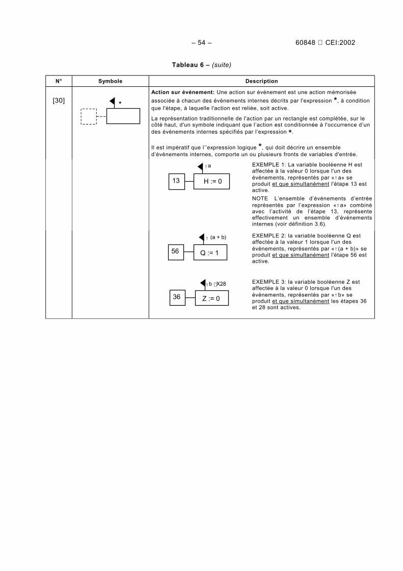
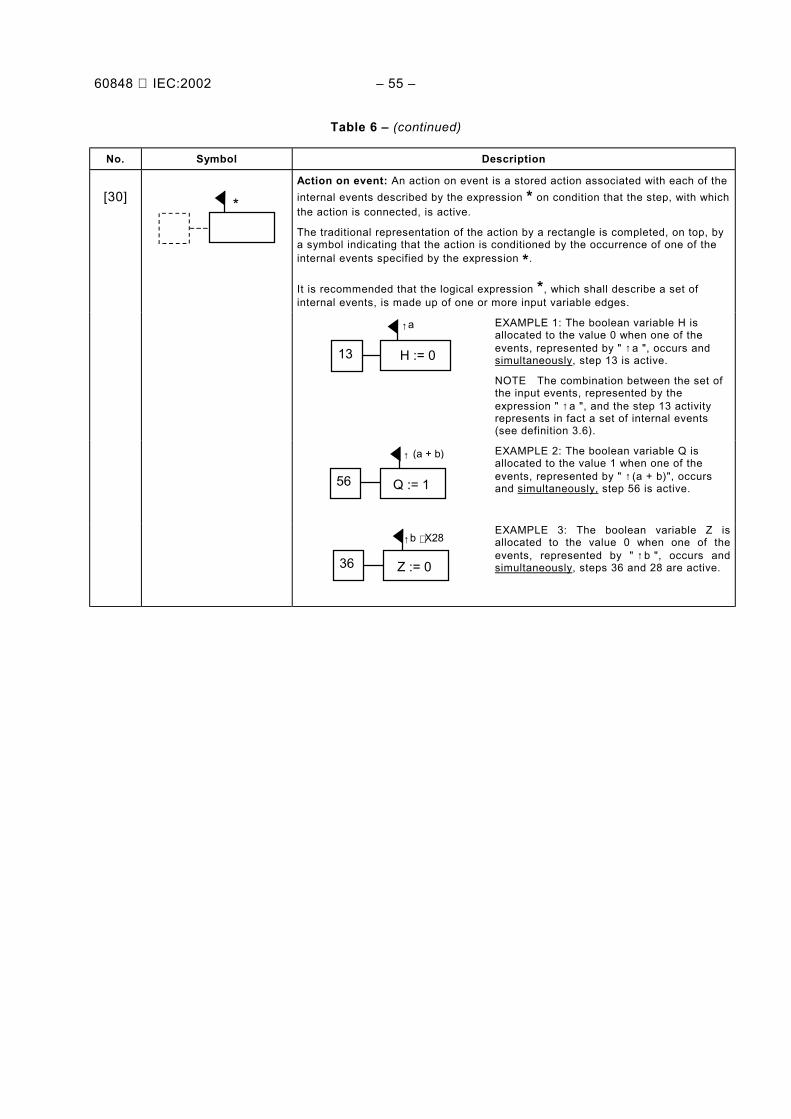
Le franchissement d'une transition, notée de manière graphique (symbole 29), décrit l'ensembledes événements internes qui ont chacun pour conséquence le franchissement de cette transition.
4.8 Modes de sortie
Les actions permettent d'établir le lien entre l'évolution du grafcet et les sorties. Deux modesde sortie, mode continu ou mode mémorisé, décrivent comment les sorties dépendent del'évolution et des entrées du système.
4.8.1 Mode continu (assignation sur état)
En mode continu c'est l'association d'une action à une étape qui permet d'indiquer qu'unevariable de sortie a la valeur vraie si l'étape est active et si la condition d'assignation estvérifiée. La condition d'assignation est une expression logique de variables d'entrée et/ou devariables internes (voir symbole 22). Si l'une des conditions n'est pas remplie et sous réservequ'aucune autre action relative à la même sortie ne satisfasse les conditions, la variable desortie considérée prend la valeur fausse.
On appelle assignation le fait d'imposer la valeur (vraie ou fausse) des variables de sortie.
L'ensemble des assignations locales (relatives aux étapes actives à un instant donné) définitl'assignation de toutes les variables de sortie pour cette situation.
Règle d’assignation: Pour une situation donnée, les valeurs des sorties relatives aux actionscontinues sont assignées:
• à la valeur vraie, pour chacune des sorties relatives aux actions associées aux étapesactives et pour lesquelles les conditions d'assignation sont vérifiées,
• à la valeur fausse, pour les autres sorties (qui ne sont pas assignées à la valeur vraie).
4.8.2 Mode mémorisé (affectation sur événement)
En mode mémorisé c'est l'association d'une action à des événements internes qui permet d'indiquerqu'une variable de sortie prend et garde la valeur imposée si l'un de ces événements se produit.
Des représentations explicites sont nécessaires (activation d'étape, désactivation d'étape,franchissement d'une transition, etc) pour décrire l'association des actions aux événements.
La valeur d'une variable de sortie relative à une action mémorisée reste inchangée tant qu'unnouvel événement spécifié ne la modifie pas.
On appelle affectation le fait de mémoriser, à un instant donné, la mise à une valeurdéterminée d'une variable de sortie.
Règle d'affectation: La valeur d'une sortie, relative à une action mémorisée et associée à unévénement, est affectée à la valeur indiquée si l'événement interne spécifié se produit; àl'initialisation la valeur de cette sortie est nulle.
4.9 Application des règles d’évolution
L’interprétation intuitive de l’évolution, dite «pas à pas», désigne la démarche progressive quipermet, sur occurrence d’un événement d’entrée et à partir de la situation antérieure, dedéterminer, par application successive des règles d’évolution sur chaque transition, la situationpostérieure à l’événement considéré. Cette facilité d’interprétation est un artifice autorisant unespécification indirecte de l'évolution, mais le spécificateur doit prendre garde au fait que lefranchissement des transitions situées sur ce chemin n'implique pas l'activation effective dessituations intermédiaires.
60848 IEC:2002 – 23 –
4.7.3 Internal events described by the clearing of a transition
The graphically noted clearing of a transition (symbol 29), describes the set of internal eventseach of which have the clearing of this transition as consequence.
4.8 Output modes
The actions enable links to establish the connection between the evolution of the grafcet chartand the outputs. Two output modes, continuous mode or stored mode, describe how theoutputs depend on the evolution and on the system inputs.
4.8.1 Continuous mode (assignation on state)
In the continuous mode, the association of an action with a step indicates that an outputvariable has a true value if the step is active and if the assignation condition is verified. Theassignation condition is a logical expression of the input variables and/or the internal ones (seesymbol 22). If one of the conditions is not met and provided that no other action relating to thesame output meets the conditions, the output variable concerned takes the false value.
Assignation refers to imposing the value of the output variables (true or false).
The set of the local assignation (relating to the active steps at a given instant) defines theassignation of all the output variables for this situation.
Assignation rule: For a given situation, the value of the outputs relating to the continuousactions is assigned:
• to the true value, for each output relating to the actions associated with active steps and forwhich the assignation conditions are verified,
• to the false value, for the other outputs (which are not assigned to the true value).
4.8.2 Stored mode (allocation on event)
In the stored mode, the association of an action to internal events is used to indicate that anoutput variable takes and maintains the enforced value if one of these events occurs.
Explicit representations are necessary to describe the association of the actions with theevents (activation step, deactivation step, clearing of a transition, etc.).
The value of an output relating to a stored action remains unchanged until a new specifiedevent modifies its value.
Allocation refers to storing, at a considered moment, a determined value affected to an outputvariable.
Allocation rule: The value of an output, relating to a stored action and associated to an event,is allocated to the indicated value, if the specified internal event occurs; the value of this outputis null at the initialisation.
4.9 Application of the evolution rules
Intuitive interpretation of the evolution, called “step by step”, designates the progressive waywhich allows, on the occurrence of an input event and from the preceding situation, todetermine the succeeding situation of this event, by the successive application of the evolutionrules on each transition. The interpretation facility is a device to enable an indirect specificationof the evolution, but the designer shall take care that the clearing of the transitions on this pathdoes not involve the effective activation of the intermediate situations.
– 24 – 60848 CEI:2002
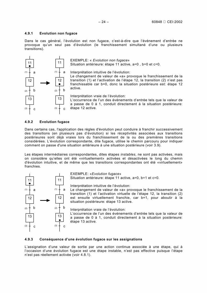
4.9.1 Evolution non fugace
Dans le cas général, l’évolution est non fugace, c’est-à-dire que l’événement d’entrée neprovoque qu’un seul pas d’évolution (le franchissement simultané d’une ou plusieurstransitions).
(1)
c
b
a
11
12
(3)
13
(2)
(1)
c
b
a
11
12
(3)
13
(2)
EXEMPLE: « Evolution non fugace»Situation antérieure: étape 11 active, a=0 , b=0 et c=0.
Interprétation intuitive de l’évolution:Le changement de valeur de «a» provoque le franchissement de latransition (1) et l’activation de l’étape 12, la transition (2) n’est pasfranchissable car b=0, donc la situation postérieure est: étape 12active.
Interprétation vraie de l’évolution:L’occurrence de l’un des événements d’entrée tels que la valeur dea passe de 0 à 1, conduit directement à la situation postérieure:étape 12 active.
4.9.2 Evolution fugace
Dans certains cas, l'application des règles d'évolution peut conduire à franchir successivementdes transitions (en plusieurs pas d’évolution) si les réceptivités associées aux transitionspostérieures sont déjà vraies lors du franchissement de la ou des premières transitionsconsidérées. L’évolution correspondante, dite fugace, utilise le chemin parcouru pour indiquercomment on passe d'une situation antérieure à une situation postérieure (voir 3.9).
Les étapes intermédiaires correspondantes, dites étapes instables, ne sont pas activées, maison considère qu’elles ont été «virtuellement» activées et désactivées le long du chemind'évolution intuitive, et de même que les transitions correspondantes ont été «virtuellement»franchies.
Interprétation intuitive de l’évolution:Le changement de valeur de «a» provoque le franchissement de latransition (1) et l’activation virtuelle de l’étape 12, la transition (2)est ensuite virtuellement franchie, car b=1, pour aboutir à lasituation postérieure: étape 13 active.
Interprétation vraie de l’évolution:L’occurrence de l’un des événements d’entrée tels que la valeur dea passe de 0 à 1, conduit directement à la situation postérieure:étape 13 active.
4.9.3 Conséquence d’une évolution fugace sur les assignations
L’assignation d’une valeur de sortie par une action continue associée à une étape, qui àl’occasion d’une évolution fugace est une étape instable, n’est pas effective puisque l’étapen’est pas réellement activée (voir 4.8.1).
60848 IEC:2002 – 25 –
4.9.1 Non transient evolution
In general, the evolution is non-transient, which means that the input event only leads to oneevolution stage (the simultaneous clearing of one or more transitions).
Intuitive interpretation of the evolution:The change in the value “a” involves the clearing of the transition(1) and the activation of the step 12, the transition (2) can not becleared, because b=0, the subsequent situation is therefore: step12 active.
Real interpretation of the evolution:The occurrence of one of the input events such as the value of achanges from 0 to 1 leads straight to the subsequent situation: step12 active.
4.9.2 Transient evolution
In some cases, the application of the evolution rules can lead to successively clearing sometransitions (in several evolution stages) if the transition-conditions associated with thesubsequent transitions are already true, when the first transitions considered are cleared. Thecorresponding description, referred to as transient, uses the path taken to indicate how tomove from a preceding situation to a succeeding situation (see 3.9).
The corresponding intermediate steps, referred to as unstable are not activated, but weconsider that they have been "virtually" activated and deactivated along the intuitive evolutionpath, as well as for the corresponding transitions which have been "virtually" cleared.
Intuitive interpretation of the evolution:The change in the value “a” involves the clearing of the transition(1) and the virtual activation of the step 12, then the transition (2) isvirtually cleared, because b=1, leading to the succeeding situation:step 13 active.
Real interpretation of the evolution:The occurrence of one of the input events, such as the value of achange from 0 to 1, leads to the succeeding situation: step 13active.
4.9.3 Consequence of a transient evolution on the assignations
The assignation of an output value by a continuous action associated with a step, which is anunstable step in the case of a transient evolution, is not effective, since the step is not reallyactivated (see 4.8.1).
– 26 – 60848 CEI:2002
(1)
c
b
B
a
11
12
(3)
13
(2)
(1)
c
b
a
11
12
(3)
13
(2)
B
EXEMPLE: «Action continue associée à une étapeinstable»Situation antérieure: étape 11 active, a=0, b=1 et c=0.
L’occurrence de l’un des événements d’entrée tels quela valeur de «a» passe de 0 à 1, conduit directement àla situation postérieure: étape 13 active.La situation antérieure (étape 11 active) et la situationpostérieure (étape 13 active) assignent à la valeur 0 lavariable de sortie B. L’étape instable 12 n’étant pasréellement activée, l’assignation à la valeur 1 de B n’estpas effective au cours de cette évolution fugace.
4.9.4 Conséquence d’une évolution fugace sur les affectations
L’affectation à une valeur déterminée d’une sortie par une action mémorisée (symbole 26)associée à une étape, qui à l’occasion d’une évolution fugace est une étape instable, esteffective puisque cette affectation est associée aux événements déclenchant cette évolution(voir 4.8.2).
(1)
c
b
B := 1
a
11
12
(3)
13
(2)
(1)
c
b
a
11
12
(3)
13
(2)
B := 1
EXEMPLE 1: «Action mémorisée associée à l’activationd’une étape instable»Situation antérieure: étape 11 active, a=0, b=1 et c=0.
L’occurrence de l’un des événements d’entrée tels quela valeur de «a» passe de 0 à 1, conduit directement àla situation postérieure: étape 13 active.L’affectation de la valeur 1 à la variable de sortie B sefait sur occurrence d’un des événements internes ayantpour conséquence l’activation réelle ou virtuelle del’étape 12.
(1)
c
b
B := 0
a
11
12
(3)
13
(2)
(1)
c
b
a
11
12
(3)
13
(2)
B := 0
EXEMPLE 2: «Action mémorisée associée à ladésactivation d’une étape instable»Situation antérieure: étape 11 active, a=0, b=1 et c=0.
L’occurrence de l’un des événements d’entrée tels quela valeur de «a» passe de 0 à 1 conduit directement àla situation postérieure: étape 13 active.L’affectation de la valeur 0 à la variable de sortie B sefait sur occurrence d’un des événements internes ayantpour conséquence la désactivation réelle ou virtuelle del’étape 12.
60848 IEC:2002 – 27 –
(1)
c
b
B
a
11
12
(3)
13
(2)
(1)
c
b
a
11
12
(3)
13
(2)
B
EXAMPLE: “Continuous action associated with anunstable step”Preceding situation: step 11 active, a=0, b=1 and c=0.
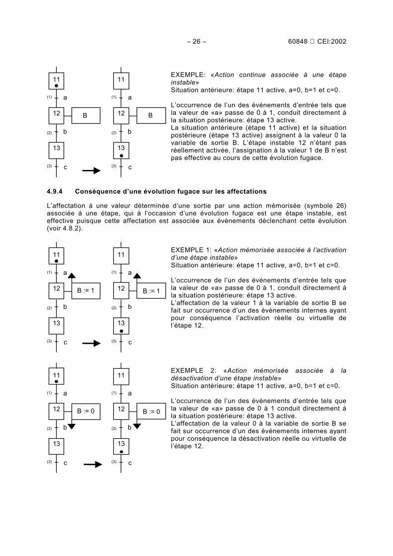
The occurrence of one of the input events such as thevalue of "a" changes from 0 to 1, leads straight to thesubsequent situation: step 13 active.The preceding situation (step 11 active) and thesucceeding situation (step 13 active) assign the value 0to the output variable B. The unstable step 12 being notreally activated, the assignation of B to the value 1 isnot effective on the transient evolution.
4.9.4 Consequence of a transient evolution on the allocations
The allocation to a determinate value of an output by a stored action (symbol 26) associated toa step, which is an unstable step in the case of a transient evolution, is effective since thisallocation is associated to the events releasing this evolution (see 4.8.2).
(1)
c
b
B := 1
a
11
12
(3)
13
(2)
(1)
c
b
a
11
12
(3)
13
(2)
B := 1
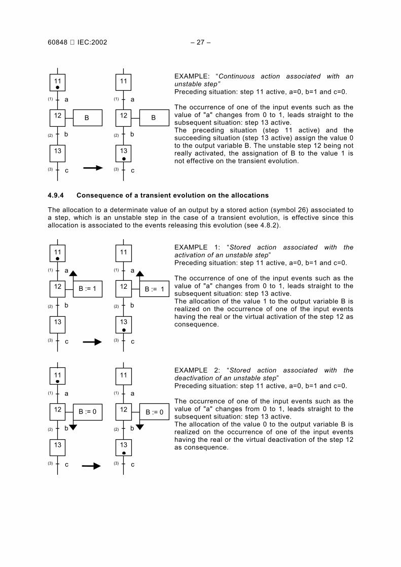
EXAMPLE 1: “Stored action associated with theactivation of an unstable step”Preceding situation: step 11 active, a=0, b=1 and c=0.
The occurrence of one of the input events such as thevalue of "a" changes from 0 to 1, leads straight to thesubsequent situation: step 13 active.The allocation of the value 1 to the output variable B isrealized on the occurrence of one of the input eventshaving the real or the virtual activation of the step 12 asconsequence.
(1)
c
b
B := 0
a
11
12
(3)
13
(2)
(1)
c
b
a
11
12
(3)
13
(2)
B := 0
EXAMPLE 2: “Stored action associated with thedeactivation of an unstable step”Preceding situation: step 11 active, a=0, b=1 and c=0.
The occurrence of one of the input events such as thevalue of "a" changes from 0 to 1, leads straight to thesubsequent situation: step 13 active.The allocation of the value 0 to the output variable B isrealized on the occurrence of one of the input eventshaving the real or the virtual deactivation of the step 12as consequence.
– 28 – 60848 CEI:2002
4.10 Comparaison entre les deux modes de sortie
Le choix du mode de sortie dépend des habitudes et des méthodologies, toutefois l'attentiondes spécificateurs est attirée sur les importantes différences entre les deux modes.
4.10.1 Détermination de la valeur des sorties• En mode continu, toutes les sorties sont assignées selon la situation, à la valeur vraie pour
les sorties désignées explicitement dans les actions associées aux étapes actives, à lavaleur fausse pour les autres qui sont désignées implicitement par omission (voir règled'assignation, 4.8.1).
• En mode mémorisé, seules les sorties affectées sont modifiées à la valeur indiquée, lesvaleurs des autres sorties mémorisées restent inchangées (voir règle d'affectation, 4.8.2).
4.10.2 Analyse de la valeur des sorties d'un grafcet à un instant déterminé• En mode continu, la connaissance de la situation et de la valeur des entrées suffit pour
déterminer la valeur des sorties (voir 4.8.1).
• En mode mémorisé, la connaissance de la situation et de la valeur des entrées ne suffitpas, il faut connaître également les évolutions antérieures pour déterminer la valeur dessorties (voir 4.8.2).
4.10.3 Actions relatives à une évolution fugace• En mode continu, les actions associées à une étape instable ne sont pas prises en compte
car cette étape n'est pas activée (voir 4.9.1).
• En mode mémorisé, les actions associées à des événements correspondant à uneévolution fugace sont prises en compte car les événements déclenchant cette évolution seproduisent (voir 4.9.2).
4.10.4 Conflit éventuel sur la valeur des sorties• En mode continu, les principes de l'assignation permettent d'éviter tout conflit d'assignation
sur une même sortie.
• En mode mémorisé, les principes de l'affectation ne permettent pas d'éviter les éventuelsconflits d'affectation sur une même sortie. Le spécificateur doit alors s'assurer lui-mêmeque deux affectations contradictoires ne peuvent pas se produire simultanément.
NOTE 1 Les deux modes de sortie peuvent être utilisés dans une même spécification en GRAFCET, mais lavaleur d’une variable de sortie est déterminée soit par assignation soit par affectation. La spécification d’uneaffectation sur une variable de sortie (mode mémorisé) exclut cette variable de toute assignation (mode continu).
NOTE 2 L’article 5 donne les symboles graphiques qui permettent de distinguer les actions continues (représen-tation par défaut) des actions mémorisées (représentation explicite selon l’ensemble des événements spécifiés).
NOTE 3 Dans le cas fréquent d'une spécification du comportement de la partie commande, l'usage industrielcourant impose d'employer le mode continu pour toutes les sorties à destination des actionneurs, et le modemémorisé pour décrire des tâches internes de commande. Ces tâches, telles qu'incrémentation d'un compteur, oumodification de la valeur d'un registre numérique, portent sur des variables internes non nécessairementbooléennes. Associées aux actions mémorisées, les tâches internes, ainsi que le calcul de prédicat associé auxréceptivités, ne sont pas décrites dans la présente norme, mais sont associées par l'usage à la description logiquedes évolutions du grafcet. Il appartient aux spécificateurs de s'assurer de la cohérence et de la clarté de leursdescriptions.
60848 IEC:2002 – 29 –
4.10 Comparison between the two output modes
The choice of the output mode depends on the practice and methodology used. However thedesigners attention is drawn to the important differences between the two modes.
4.10.1 Determination of the value of the outputs• In continuous mode, all the outputs are assigned according to the situation, to the true
value for the outputs explicitly indicated in the actions associated to the active steps, and tothe false value for the other ones which are implicitly set by omission (see assignation rule,4.8.1).
• In the stored mode, only the considered outputs are modified according to the indicatedvalue, the other stored values of the outputs remain unchanged (see allocation rule, 4.8.2).
4.10.2 Analysis of the value of the outputs for a grafcet-chart at a defined instant• In the continuous mode, the knowledge of the situation and the value of the inputs is
sufficient to determine the value of the outputs (see 4.8.1).
• In the stored mode, the knowledge of the situation and the value of the inputs is notsufficient, the preceding evolutions shall also be known to determine the value of theoutputs (see 4.8.2).
4.10.3 Actions relative to transient evolution• In the continuous mode, the actions associated with an unstable step are not taken into
consideration because this step is not activated (see 4.9.1).
• In the stored mode, the actions associated with events and in relation with a transientevolution are taken into consideration because the triggered events releasing this evolutionoccur (see 4.9.2).
4.10.4 Possible conflict on the value of the outputs• In the continuous mode, the assignation principles ensure every assignation conflict on the
particular output to be avoided.
• In the stored mode, the allocation rules do not allow the possible assignation conflicts on asame output to be avoided. The designer shall ensure that two contradictory allocations cannot occur simultaneously.
NOTE 1 Both output modes can be used in one specification in GRAFCET, but the value of an output variable isdetermined either by assignation or by allocation. The specification of an allocation to an output variable (storedmode), excludes this output variable of any assignation (continuous mode).
NOTE 2 Clause 5 gives the graphic symbols which enable the stored actions (indicated by explicit representationaccording to the set of specified events) to be distinguished from the continuous ones (indicated by absence of anyrepresentation).
NOTE 3 In the frequent case of the specification of control system behaviour, the current industrial practice forcesthe employment of the continuous mode for all the outputs to the actuators, and the stored mode for describinginternal control tasks. These tasks, such as the incrementation of a counter, or the modification of the value for anumerical register, refer to internal variables, which are not necessarily Boolean ones. The internal tasksassociated with the stored actions, as well as the calculation of expressions associated with transition-conditions,are not described in the present standard, but are associated by the use of the logical description of the grafcetevolutions. The designers should take care to make their descriptions consistent and clear.
– 30 – 60848 CEI:2002
5 Représentation graphique des éléments
Les éléments du GRAFCET possèdent une représentation symbolique qui permet, en lesassociant correctement, de réaliser des diagrammes fonctionnels clairs et synthétiques.
NOTE 1 Seule la représentation globale des symboles est imposée, les dimensions et les éléments de détail(épaisseur des traits, police de caractère, etc.) sont laissés libres aux utilisateurs.
NOTE 2 Les représentations en trait pointillé indiquent le contexte du symbole.
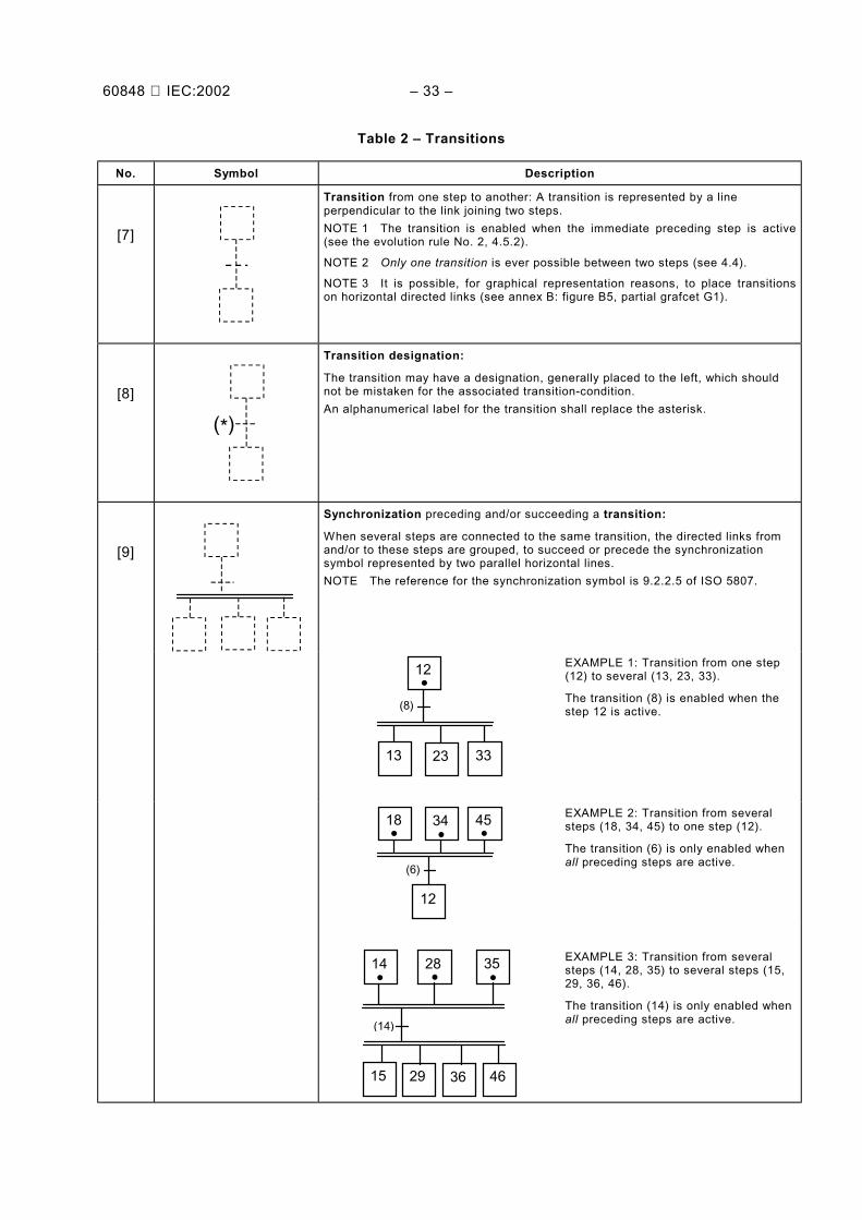
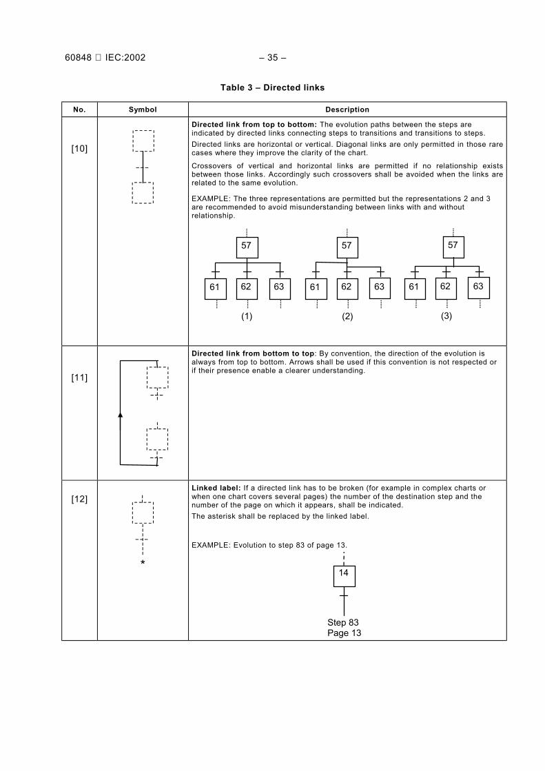
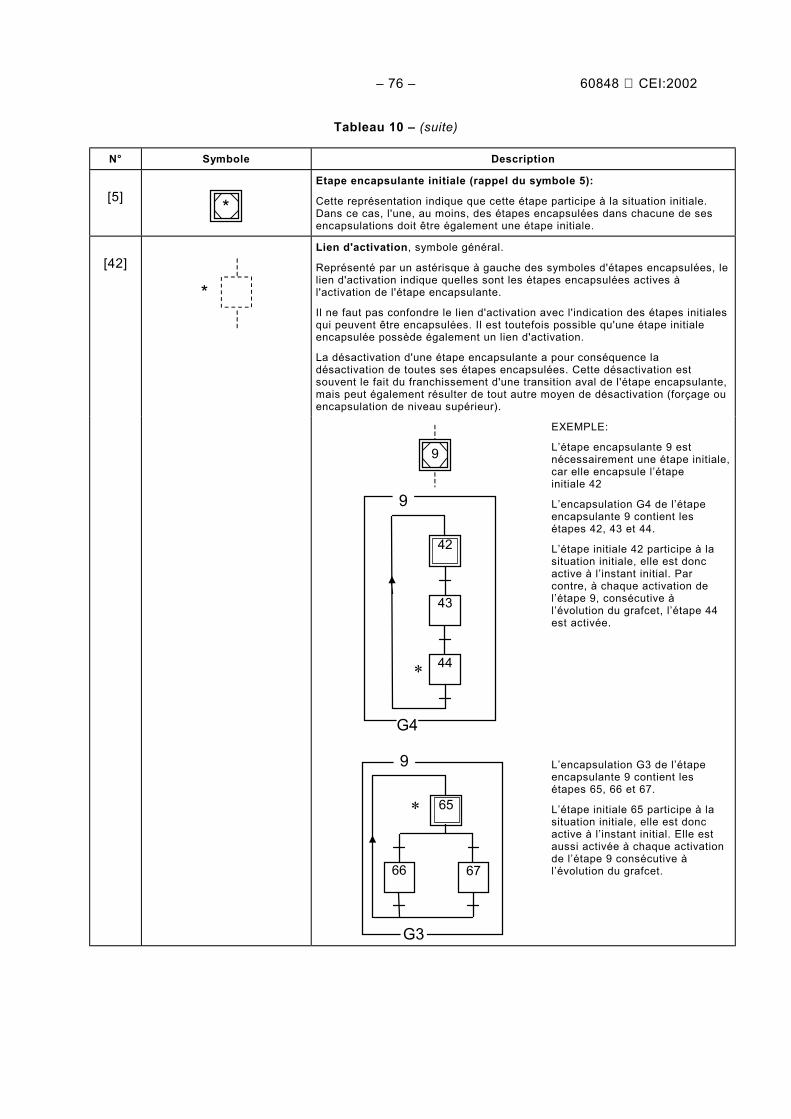
Tableau 1 – Étapes
N° Symbole Description
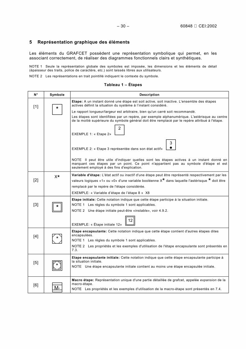
[1] *Etape: A un instant donné une étape est soit active, soit inactive. L'ensemble des étapesactives définit la situation du système à l’instant considéré.
Le rapport longueur/largeur est arbitraire, bien qu'un carré soit recommandé.Les étapes sont identifiées par un repère, par exemple alphanumérique. L'astérisque au centrede la moitié supérieure du symbole général doit être remplacé par le repère attribué à l'étape.
EXEMPLE 1: « Etape 2» 2
EXEMPLE 2: « Etape 3 représentée dans son état actif» 3
NOTE Il peut être utile d'indiquer quelles sont les étapes actives à un instant donné enmarquant ces étapes par un point. Ce point n'appartient pas au symbole d'étape et estseulement employé à des fins d'explication.
[2]X* Variable d'étape: L'état actif ou inactif d'une étape peut être représenté respectivement par les
valeurs logiques «1» ou «0» d'une variable booléenne X* dans laquelle l'astérisque * doit être
remplacé par le repère de l'étape considérée.
EXEMPLE: « Variable d’étape de l’étape 8 » X8
[3] *Etape initiale: Cette notation indique que cette étape participe à la situation initiale.NOTE 1 Les règles du symbole 1 sont applicables.
NOTE 2 Une étape initiale peut-être «instable», voir 4.9.2.
EXEMPLE: « Étape initiale 12» 12
[4] *Etape encapsulante: Cette notation indique que cette étape contient d'autres étapes ditesencapsulées.NOTE 1 Les règles du symbole 1 sont applicables.
NOTE 2 Les propriétés et les exemples d'utilisation de l'étape encapsulante sont présentés en7.3.
[5] *Etape encapsulante initiale: Cette notation indique que cette étape encapsulante participe àla situation initiale.NOTE Une étape encapsulante initiale contient au moins une étape encapsulée initiale.
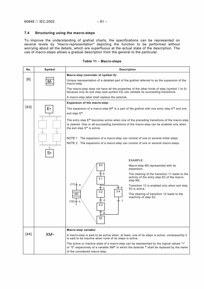
[6] M*
Macro étape: Représentation unique d'une partie détaillée de grafcet, appelée expansion de lamacro-étape.NOTE Les propriétés et les exemples d'utilisation de la macro-étape sont présentés en 7.4.
60848 IEC:2002 – 31 –
5 Graphical representation of the elements
The elements of GRAFCET have their own symbolic representation which when correctlyassociated, enable clear and synthetic function-charts to be implemented.
NOTE 1 Only the global representation of the symbols is imposed; dimensions and details (thickness of lines, fontof characters, etc.) are left up to the users.
NOTE 2 The stippled representation indicates the context of the symbol.
Table 1 – Steps
No. Symbol Description
[1] *Step: At a given moment, a step is either active or inactive. The set of active steps defines thesituation of the given system at the considered instant.The height-width ratio of the rectangle is arbitrary, although a square is recommended.
For the purposes of identification, the steps shall have a label, for example, alphanumerical.The label assigned to the step shall replace the asterisk at the upper half of the general symbol.
EXAMPLE 1: “ Step 2 “ 2
EXAMPLE 2: “ Step 3 represented in its active state “ 3
NOTE It may be useful to indicate which steps are active at a given instant by marking thesesteps with a dot. This dot is not part of the step symbol and is only used for explanatorypurposes.
[2]X*
Step variable: The active or inactive state of the step may be represented by the logical values"1" or "0" respectively of a boolean variable X*, in which the asterisk* shall be replaced by the
label of the relevant step.
EXAMPLE: “ Step variable of the step 8 ” X8
[3] *Initial step: This symbol means that this step participates in the initial situation.NOTE 1 The rules of the symbol 1 apply.
NOTE 2 An initial step could be “ unstable”, see 4.9.2.
EXAMPLE: “ Initial step 12 “ 12
[4] *Enclosing step: This symbol indicates that this step contains other steps referred to asenclosed steps.NOTE 1 The rules of the symbol 1 apply.
NOTE 2 The properties and the examples of the use of the enclosing step are given in 7.3.
[5] *Initial enclosing step: This symbol means that this enclosing step participates in the initialsituation.NOTE An initial enclosing step contains at least one enclosed initial step.
[6] M*
Macro-step: Unique representation of a detailed part of the function-chart referred to as theexpansion of the macro-step.NOTE The properties and the examples of the use of the macro-step are given in 7.4.
– 32 – 60848 CEI:2002
Tableau 2 – Transitions
N° Symbole Description
[7]
Transition entre deux étapes: Une transition est représentée par un traitperpendiculaire aux liaisons joignant deux étapes.NOTE 1 La transition est validée lorsque l'étape amont est active (voir règled’évolution N° 2, 4.5.2).
NOTE 2 Il n'y a toujours qu'une seule transition entre deux étapes (voir 4.4).
NOTE 3 Il est possible, pour des raisons de représentation graphique, de placerdes transitions sur des segments de liaison horizontaux (voir annexe B: figure B.5,grafcet partiel G1).
[8]
(*)
Repère de transition:
La transition peut comporter un repère, placé généralement à sa gauche, qu'il nefaut pas confondre avec la réceptivité associée à la transition.L'astérisque doit être remplacé par le repère alphanumérique de la transition.
[9]
Synchronisation en amont et/ou aval d'une transition:
Lorsque plusieurs étapes sont reliées à la même transition, les liaisons orientéesd'entrée et/ou de sortie de ces étapes sont regroupées en amont ou en aval par lesymbole de synchronisation représenté par deux traits parallèles horizontaux.NOTE La référence du symbole de synchronisation est le paragraphe 9.2.2.5 del'ISO 5807.
(8)
12
13 23 33
EXEMPLE 1: Transition d’une étape (12)vers plusieurs (13,23,33).
La transition (8) est validée lorsquel’étape (12) est active.
(6)
12
18 34 45 EXEMPLE 2: Transition de plusieursétapes (18,34,45) vers une (12).
La transition (6) n'est validée quelorsque toutes les étapes amont sontactives.
(14)
14 28 35
4629 3615
EXEMPLE 3: Transition de plusieursétapes (14,28,35) vers plusieurs(15,29,36,46).
La transition (14) n'est validée quelorsque toutes les étapes amont sontactives.
60848 IEC:2002 – 33 –
Table 2 – Transitions
No. Symbol Description
[7]
Transition from one step to another: A transition is represented by a lineperpendicular to the link joining two steps.NOTE 1 The transition is enabled when the immediate preceding step is active(see the evolution rule No. 2, 4.5.2).
NOTE 2 Only one transition is ever possible between two steps (see 4.4).
NOTE 3 It is possible, for graphical representation reasons, to place transitionson horizontal directed links (see annex B: figure B5, partial grafcet G1).
[8]
(*)
Transition designation:
The transition may have a designation, generally placed to the left, which shouldnot be mistaken for the associated transition-condition.An alphanumerical label for the transition shall replace the asterisk.
[9]
Synchronization preceding and/or succeeding a transition:
When several steps are connected to the same transition, the directed links fromand/or to these steps are grouped, to succeed or precede the synchronizationsymbol represented by two parallel horizontal lines.NOTE The reference for the synchronization symbol is 9.2.2.5 of ISO 5807.
(8)
12
13 23 33
EXAMPLE 1: Transition from one step(12) to several (13, 23, 33).
The transition (8) is enabled when thestep 12 is active.
(6)
12
18 34 45 EXAMPLE 2: Transition from severalsteps (18, 34, 45) to one step (12).
The transition (6) is only enabled whenall preceding steps are active.
(14)
14 28 35
4629 3615
EXAMPLE 3: Transition from severalsteps (14, 28, 35) to several steps (15,29, 36, 46).
The transition (14) is only enabled whenall preceding steps are active.
– 34 – 60848 CEI:2002
ableau 3 – Liaisons orientées
N° Symbole Description
[10]
Liaison orientée de haut en bas: Les voies d'évolution entre les étapes sontindiquées par des liaisons orientées reliant les étapes aux transitions et les transitionsaux étapes.
Les liaisons orientées sont horizontales ou verticales. Des liaisons obliques sonttoutefois permises dans les cas exceptionnels où elles apportent plus de clarté audiagramme.
Les croisements de liaisons verticales et horizontales sont admis s'il n'existe aucunerelation entre ces liaisons. En conséquence, de tels croisements doivent être évitéslorsque les liaisons correspondent à la même évolution.
EXEMPLE: Les trois représentations sont admissibles, mais les représentations 2 et 3sont recommandées pour éviter la confusion entre croisement sans et avec liaison.
57
6362
(2)(1)
61
57
636261
57
6362
(3)
61
[11]
Liaison orientée de bas en haut: Par convention le sens d'évolution est toujours duhaut vers le bas. Des flèches doivent être utilisées si cette convention n'est pasrespectée ou si leur présence peut apporter une meilleure compréhension.
[12]
*
Repère de liaison: Lorsqu'une liaison orientée doit être interrompue (par exempledans des dessins complexes ou dans le cas de représentation sur plusieurs pages), lerepère de l'étape de destination ainsi que le repère de la page à laquelle elle apparaîtdoivent être indiqués.L'astérisque doit être remplacé par le repère de liaison.
EXEMPLE: Evolution vers l'étape 83 de la page 13.
Etape 83Page 13
14
60848 IEC:2002 – 35 –
Table 3 – Directed links
No. Symbol Description
[10]
Directed link from top to bottom: The evolution paths between the steps areindicated by directed links connecting steps to transitions and transitions to steps.Directed links are horizontal or vertical. Diagonal links are only permitted in those rarecases where they improve the clarity of the chart.
Crossovers of vertical and horizontal links are permitted if no relationship existsbetween those links. Accordingly such crossovers shall be avoided when the links arerelated to the same evolution.
EXAMPLE: The three representations are permitted but the representations 2 and 3are recommended to avoid misunderstanding between links with and withoutrelationship.
57
6362
(2)(1)
61
57
636261
57
6362
(3)
61
[11]
Directed link from bottom to top: By convention, the direction of the evolution isalways from top to bottom. Arrows shall be used if this convention is not respected orif their presence enable a clearer understanding.
[12]
*
Linked label: If a directed link has to be broken (for example in complex charts orwhen one chart covers several pages) the number of the destination step and thenumber of the page on which it appears, shall be indicated.The asterisk shall be replaced by the linked label.
EXAMPLE: Evolution to step 83 of page 13.
Step 83Page 13
14
– 36 – 60848 CEI:2002
Tableau 4 – Réceptivités associées aux transitions
N° Symbole Description
[13]
*
Réceptivité associée à une transition:
Une proposition logique, appelée réceptivité, qui peut être vraie ou fausse, estassociée à chaque transition. S'il existe une variable logique correspondante, elleest égale à 1 quand la réceptivité est vraie et égale à 0 quand la réceptivité estfausse. La proposition logique formant la réceptivité est constituée d'une ouplusieurs variables booléennes (variable d'entrée, variable d'étape, valeur d'unprédicat, etc.).L'astérisque doit être remplacé par la description de la réceptivité associée à latransition sous forme d'un texte, d'une expression booléenne, ou à l'aide desymboles graphiques.
Portillon fermé (a) et (pasde pression ( b ) ouprésence pièce (c) )
12
13
EXEMPLE 1: Description de laréceptivité par un texte.
a ⋅ ( b + c)
12
13
EXEMPLE 2: Réceptivité décrite parune expression booléenne.
[14] 1
Réceptivité toujours vraie:
La notation « 1 » indique que la réceptivité est toujours vraie.NOTE Dans ce cas, l'évolution est dite toujours fugace (voir 4.9.2), lefranchissement de la transition n'est conditionné que par l'activité de l'étapeamont.
60848 IEC:2002 – 37 –
Table 4 – Associated transition-conditions
No. Symbol Description
[13]
*
Transition-condition:
A logical proposition, called a transition-condition, which can be either true orfalse, is associated with each transition. If a corresponding logical variable exists,it is equal to 1 when the transition-condition is true or equal to 0 when thetransition-condition is false. The logical proposition forming the transition-conditioncomprises one or several boolean variables, (input variable, step variable,predicate value, etc).The asterisk shall be replaced by the description of the transition-condition in theform of text, of a boolean expression, or by using graphical symbols.
Door closed (a) and (nopressure ( b ) or partpresented (c) )
12
13
EXAMPLE 1: Transition-conditiondescribed by a text.
a ⋅ ( b + c)
12
13
EXAMPLE 2: Transition-conditiondescribed by a boolean expression.
[14] 1
Transition-condition always true:
The symbol "1" means that the transition-condition is always true.NOTE In this case, the evolution is to be transient (see 4.9.2), the clearing of thetransition is only conditioned by the activity of the preceding step.
– 38 – 60848 CEI:2002
Tableau 4 – (suite)
N° Symbole Description
[15]
↑*
Front montant d'une variable logique:
La notation « ↑ » indique que la réceptivité n'est vraie qu'au changement d'état de lavariable * (front montant: passage de la valeur 0 à la valeur 1, voir la note de 4.6).
Cette notation est générale et s'applique à toute proposition logique, qu'il s'agisse d'unevariable élémentaire ou d'une combinaison de plusieurs variables booléennes.
↑a
3
4
EXEMPLE 1: La réceptivité associée à latransition n'est vraie que lorsque a passe del'état 0 à l'état 1.NOTE En application de la règle d'évolutionN° 2, la transition n'est franchie que sur unfront montant de a postérieur à la validation dela transition par l'activité de l'étape 3.
a + ↑b
3
4
EXEMPLE 2: La réceptivité associée à latransition n'est vraie que lorsque a est vraie ouque b passe de l'état 0 à l'état 1.
[16] ↓*
Front descendant d'une variable logique:
La notation «↓ » indique que la réceptivité n'est vraie qu'au changement d'état de lavariable * (front descendant: passage de la valeur 1 à la valeur 0, voir la note de 4.6).
Cette notation est générale et s'applique à toute proposition logique, qu'il s'agisse d'unevariable élémentaire ou d'une combinaison de plusieurs variables booléennes.
↓ (a ⋅ b)
3
4
EXEMPLE: La réceptivité associée à latransition n'est vraie que lorsque le produitlogique «a ⋅ b» passe de l'état 1 à l'état 0.
60848 IEC:2002 – 39 –
Table 4 – (continued)
No. Symbol Description
[15]
↑*
Rising edge of a logical variable:
The symbol " ↑ " means that the transition-condition is only true at the change of thestate of the variable * (rising edge: changing from value 0 to value 1, see the note in4.6).
This symbol is general and applies to all logical propositions, either for an elementaryvariable or for a set of several boolean variables.
↑a
3
4
EXAMPLE 1: The associated transition-condition is only true when a changes fromstate 0 to state 1.NOTE By applying the evolution rule No. 2, thetransition is only cleared on a rising edge of aafter the transition has been enabled by theactivity of step 3.
a + ↑b
3
4
EXAMPLE 2: The associated transition-condition is true only when a is true or when bchanges from state 0 to state 1.
[16] ↓*
Falling edge of a logical variable:
The symbol " ↓ " means that the transition-condition is only true on the change of thestate of the variable * (falling edge: changing from value 1 to value 0, see the note in4.6).
This symbol is general and applies to all logical propositions, either for an elementaryvariable or for a set of several boolean variables.
↓ (a ⋅ b)
3
4
EXAMPLE: The associated transition-conditionis true only when the logical product "a ⋅ b"changes from state 1 to state 0.
– 40 – 60848 CEI:2002
Tableau 4 – (suite)
N° Symbole Description
[17]
t1/*/t2
Réceptivité dépendante du temps:
La notation «t1/*/t2» indique que la réceptivité n'est vraie qu'après un temps t1 depuisl'occurrence du front montant (↑ *) de la variable temporisée et redevient fausse après untemps t2 depuis l'occurrence du front descendant (↓ *).
L'astérisque doit être remplacé par la variable que l'on désire temporiser, par exempleune variable d'étape ou une variable d'entrée.
t1 et t2 doivent être remplacés par leur valeur réelle exprimée dans l'unité de tempschoisie.
La variable temporisée doit rester vraie pendant un temps égal ou supérieur à t1 pourque la réceptivité puisse être vraie.NOTE Cette notation est celle de l'opérateur à retard défini par la CEI 60617-12(symbole n° 12-40-01).
3s/a/7s
14
15
EXEMPLE: La réceptivité associée à latransition n'est vraie que 3 s après que apasse de l'état 0 à l'état 1, elle ne redevientfausse que 7 s après que a passe de l'état 1à l'état 0.
[18]
t1/X*
Simplification usuelle du symbole 17:
L'utilisation la plus courante est la temporisation de variable d'étape avec un temps t2égal à zéro, ainsi la réceptivité devient fausse dès la désactivation de l'étapetemporisée *.
L'astérisque doit être remplacé par le repère de l'étape que l'on désire temporiser.
L'étape temporisée doit rester active pendant un temps supérieur ou égal à t1 pour quela réceptivité puisse être vraie.
Il est possible d'utiliser cette notation lorsque l'étape temporisée n'est pas l'étape amontde la transition.
4s/X27
27
28
EXEMPLE: La réceptivité associée à latransition sera vraie 4 s après l'activation del'étape 27, et sera fausse du fait dufranchissement de la transition qui désactivel'étape amont.
Dans ce cas, la durée d'activité de l'étape 27est de 4 s.
60848 IEC:2002 – 41 –
Table 4 – (continued)
No. Symbol Description
[17]
t1/*/t2
Time dependent transition-condition:
The notation " t1/*/t2 " indicates that the transition-condition is true only after a time t1from the occurrence of the rising edge (↑ *) of the time limited variable and becomesfalse again after a time t2 from the occurrence of the falling edge (↓ *).
The asterisk shall be replaced by the time-delayed variable, for example a step variableor an input variable.
t1 and t2 shall be replaced by their real value expressed in the selected time unit.
The time-delayed variable shall remain true for a period equal to or greater than t1 forthe transition-condition be true.NOTE This notation is that of the delay element defined by the standard IEC 60617-12(symbol No. 12-40-01).
3s/a/7s
14
15
EXAMPLE: The transition-condition is true3 s after the change of "a" from state 0 to thestate 1, it becomes false 7 s after the changeof a from state 1 to the state 0.
[18]
t1/X*
Usual simplification of the symbol 17:
Current use is to delay the step variable by a time t2 equal to zero, then, the transition-condition becomes false on deactivation of the step * that activated the delay.
The asterisk shall be replaced by the label of the step which is required to be delayed.
The time delayed step shall remain active during a time equal to or greater than t1 forthe transition-condition be true.
This notation can be used when the time-delayed step is not the preceding step of thetransition.
4s/X27
27
28
EXAMPLE: The transition-condition will betrue during 4 s after the activation of step 27,and will be false with the clearing of thetransition which deactivates the precedingstep.
In this case, the duration of the activity of thestep 27 is 4 s.
– 42 – 60848 CEI:2002
Tableau 4 – (suite)
N° Symbole Description
[19]
[*]
Valeur booléenne d'un prédicat:
La notation «[*]» signifie que la valeur booléenne du prédicat constitue la variable deréceptivité. Ainsi, lorsque l'assertion * est vérifiée, le prédicat vaut 1, dans le cascontraire, il vaut 0.
L'astérisque doit être remplacé par l'assertion que l'on veut tester.
La variable booléenne de prédicat peut être associée à d'autres variables logiques pourconstituer une proposition logique de réceptivité.
[C1= 3]
32
33
EXEMPLE 1: La réceptivité associée à latransition est vraie lorsque l'assertion«C1 = 3» est vérifiée.
[Valeur courante ducompteur C1 égale à trois]
32
33
EXEMPLE 1a: La réceptivité associée à latransition est vraie lorsque la valeurcourante du compteur C1 est égale à 3.NOTE La forme de l’assertion n’est pasimposée, par exemple un langage littéralpeut être utilisé.
[t > 8°C] ⋅ k
56
57
EXEMPLE 2: La réceptivité associée à latransition est vraie lorsque l'assertion«t>8 °C» est vérifiée et que la variablebooléenne k vaut 1, c'est-à-dire lorsque latempérature t est supérieure à la valeur8 °C et que le niveau haut k est atteint.
b + [R1 ≠ 24]
64
65
EXEMPLE 3: La réceptivité associée à latransition est vraie lorsque la variablebooléenne b vaut 1 ou que l'assertion «R1≠ 24» est vérifiée, c'est-à-dire lorsque labillette est en place b, ou que le registreR1 n'a pas encore atteint la valeur 24.
60848 IEC:2002 – 43 –
Table 4 – (continued)
No. Symbol Description
[19]
[*]
Boolean value of a predicate:
" [*] " indicates that the boolean value of the predicate constitutes the transition-condition variable. Therefore when the assertion * is verified, the predicate has value of1, otherwise the predicate has a value of 0.
The asterisk shall be replaced by the assertion, which shall be tested.
The boolean variable of the predicate can be associated with other logical variables toconstitute a logical proposition of transition-condition.
[C1= 3]
32
33
EXAMPLE 1: The transition-condition istrue when the assertion "C1=3" is verified.
[Current value of thecounter C1 equal 3]
32
33
EXAMPLE 1a: The transition-condition istrue when the current value of the counterC1 is equal to 3.NOTE The form of the assertion is notimposed; for example a literal languagecan be used.
[t > 8 °C] ⋅ k
56
57
EXAMPLE 2: The transition-condition istrue when the assertion " t>8 °C " isverified and when the boolean variable khas a value of "1", that means, when thetemperature t is higher than the value8 °C and when the high level k is reached.
b + [R1 ≠ 24]
64
65
EXAMPLE 3: The transition-condition istrue when the boolean variable "b" has avalue of 1 or when the assertion "R1 ≠ 24"is verified, that means when the part is atthe place b, or when the register R1 hasnot yet reached the value of 24.
– 44 – 60848 CEI:2002
Tableau 5 – Actions continues
N° Symbole Description
[20]Action continue: Une action continue est nécessairement associée à une étape.Plusieurs actions peuvent être associées à une même étape.
Le rapport longueur/largeur est arbitraire, bien qu'un rectangle de hauteur égale àl'étape soit recommandé.
A défaut d'une symbolisation explicite d'action mémorisée (symboles 27 à 30), lesymbole général rectangulaire associé à une étape désigne toujours une actioncontinue.
[21] *Libellé d'assignation d'une sortie: Toute action doit posséder un libellé sis dansle rectangle représentant cette action. Le libellé d'une action continue est ladésignation de la variable de sortie assignée à la valeur vraie selon la règled'assignation (voir 4.8.1).
L'astérisque doit être remplacé par le libellé désignant la variable de sortie.
L'expression littérale du libellé peut prendre une forme impérative ou une formedéclarative, seule compte la référence à la sortie.
L'ordre dans lequel les actions sont représentées n'implique aucune séquenceentre les actions.
EXEMPLE 1: Différentes formes, littérales et symboliques, de libellé d'actionfaisant référence à la sortie dont la valeur vraie doit provoquer l'ouverture de lavanne 2.
4 Ouvrir vanne 2
4 vanne 2
4 YV2
EXEMPLE 2: Différentes représentations (1, 2, 3, 4) de l'association de plusieursactions à une même étape.
(1)
(2)
(3) (4)
6 A B C
6 A B C
6 A
B
C
6 A
B
C
NOTE Les quatre représentations sont strictement équivalentes. Les représen-tations (2) et (4) peuvent être considérées respectivement comme dessimplifications des représentations (1) et (3).
60848 IEC:2002 – 45 –
Table 5 – Continuous actions
No. Symbol Description
[20]Continuous action: A continuous action is necessarily associated with a step.Several actions can be associated with one step.
The height-width ratio is arbitrary although a rectangle of the same height as thestep is recommended.
In the absence of an explicit symbolisation of a stored action (symbols 27 to 30),the general rectangular symbol associated with a step always designates acontinuous action.
[21] *Assignation label of an output: Each action shall have a label inside therectangle, which refers to this action. The label of a continuous action is thedesignation of the output variable assigned to the true value according to theassignation rule (see 4.8.1).
The asterisk shall be replaced by the wording of the output variable.
The textual expression of the label can take an imperative or indicated form, theonly important point is the reference to the output.
The order in which the actions are represented does not imply any sequencebetween the actions.
EXAMPLE 1: Different forms, literal or symbolic, of an action label which refer tothe output when the value is true, will provoke valve 2 to open.
4 To open valve 2
4 valve 2
4 YV2
EXAMPLE 2: Different representations (1, 2, 3, 4) of the association of severalactions at one step.
(1)
(2)
(3) (4)
6 A B C
6 A B C
6 A
B
C
6 A
B
C
NOTE The four representations are strictly equivalent. Representation (2) and (4)may be considered respectively as simplifications of the representation (1) and (3).
– 46 – 60848 CEI:2002
Tableau 5 – (suite)
N° Symbole Description
[22]*
Condition d'assignation: Une proposition logique, appelée conditiond'assignation, qui peut être vraie ou fausse, conditionne toute action continue.L'absence de notation signifie que la condition d’assignation est toujours vraie.
L'astérisque doit être remplacé par la description de la condition d'assignationsous forme d'un texte, ou d'une expression booléenne entre des variablesd'entrées et/ou des variables internes.
La condition d’assignation ne doit jamais comporter de front de variable (voir lessymboles 15 et 16), car l’action continue n’est évidemment pas mémorisée,l’assignation sur événement n’ayant aucun sens (voir 4.8.2).
EXEMPLE 1: La sortie V2 est assignée à la valeur vraie lorsque l'étape 24 estactive et lorsque la condition d'assignation d est vraie. Dans le cas contraire, lasortie V2 est assignée à la valeur fausse.
Autrement dit (sous forme d'une équation booléenne): V2 = X24 ⋅ d
24d
V2NOTE X24 est la variable d'étape reflétant l'activité de l'étape 24.
EXEMPLE 2: La sortie V2 est assignée à la valeur vraie lorsque l'étape 24 estactive (la condition d’assignation étant toujours vraie). Dans le cas contraire, lasortie V2 est assignée à la valeur fausse.
Autrement dit (sous forme d'une équation booléenne): V2 = X24
24 V2
[23]t1/*/t2
Condition d'assignation dépendante du temps: La notation «t1/*/t2» indiqueque la condition d'assignation n'est vraie qu'après un temps t1 depuis l'occurrencedu front montant (↑*, voir symbole 15) de la variable temporisée * et redevient
fausse après un temps t2 depuis l'occurrence du front descendant (↓*, voirsymbole 16).
L'astérisque doit être remplacé par la variable que l'on désire temporiser, parexemple une variable d’étape ou une variable d'entrée.
t1 et t2 doivent être remplacés par leur valeur réelle exprimée dans l'unité detemps choisie.
La variable temporisée doit rester vraie pendant un temps égal ou supérieur à t1pour que la condition d’assignation puisse être vraie.
NOTE Cette notation est celle de l'opérateur à retard défini par la CEI 60617-12(symbole n° 12-40-01).
EXEMPLE: La condition d'assignation n’est vraie que 3 s après que «a» passe del'état «0» à l'état «1», elle ne redevient fausse que 7 s après que «a» passe del'état «1» à l'état «0».
273s/a/7s
B
La valeur de la sortie B dépend de l'activité de l'étape 27 et de la valeur de lacondition d'assignation (voir règles d'assignation en 4.8.1).
60848 IEC:2002 – 47 –
Table 5 – (continued)
No. Symbol Description
[22]*
Assignation condition: A logical proposition, called an assignation condition,which can be true or false, influences any continuous action. The absence ofnotation indicates that the condition is always true.The assignation condition description in text format, or a boolean expressionbetween the input variables and/or the internal variables shall replace the asterisk.
This assignation condition shall never include an edge of variable (see symbols 15and 16), because the continuous action is of course not memorised, an assignationon event having no meaning (see 4.8.2).
EXAMPLE 1: Output V2 is assigned to the true value when step 24 is active andwhen the assignation condition d is true. In the opposite case, output V2 isassigned to the false value.
In other words (as a boolean equation): V2 = X24 ⋅ d
24d
V2NOTE X24 is the step variable which reflects the activity of step 24.
EXAMPLE 2: Output V2 is assigned to the true value when step 24 is active (theassignation condition is always true). In the opposite case, output V2 is assignedto the false value.
In other words (as a boolean equation): V2 = X24
24 V2
[23]t1/*/t2
Time dependent assignation condition: The notation "t1/*/t2" indicates that theassignation condition is true only after a time t1 from the occurrence of the risingedge (↑*, see symbol 15) of the timed variable * and becomes false again after a
time t2 from the occurrence of the falling edge (↓*, see symbol 16)
The asterisk shall be replaced by the timed variable, for instance a step variable oran input variable.
t1 and t2 shall be replaced by their real value expressed in the selected time unit.
The limited variable shall remain true for a time equal to or greater than t1 for theassignation condition to be true.NOTE This notation is that of the delay element defined by IEC 60617-12 (symbolNo. 12-40-01).
EXAMPLE: The assignation condition is true only 3 s after "a" changes from state"0" to state "1", and false 7 s after "a" changes from state "1" to state "0".
273s/a/7s
B
The value of output B depends on the activity of step 27 and on the value of theassignation condition (see assignation rules 4.8.1).
– 48 – 60848 CEI:2002
Tableau 5 – (suite)
N° Symbole Description
[24] *t1/X*
Action retardée: L'action retardée est une action continue dont la conditiond'assignation n'est vraie qu'après une durée t1 spécifiée depuis l'activation del'étape associée *, dans le but de retarder l'assignation à la valeur vraie de lasortie correspondante.
EXEMPLE: La sortie B est assignée à la valeur vraie lorsque 3 s se sont écouléesdepuis l'activation de l'étape 27.
273s/X27
B
NOTE Si la durée d'activité de l'étape 27 est inférieure à 3 s, la variable de sortie Bn'est pas assignée à la valeur vraie.
[25]*
t1/X*
Action limitée dans le temps: L'action limitée dans le temps est une actioncontinue dont la condition d'assignation n'est vraie que pendant une durée t1spécifiée depuis l'activation de l'étape * à laquelle elle est associée, dans le butde limiter la durée d'assignation à la valeur vraie de la sortie correspondante.
EXEMPLE 1: La sortie B n'est assignée à la valeur vraie que pendant 6 s depuisl'activation de l'étape 28.
286s/X28
B
NOTE Si la durée d'activité de l'étape 28 est inférieure à 6 s, la variable desortie B est assignée à la valeur vraie uniquement pendant la durée d'activité del'étape 28.
Représentation équivalente: On peut, pour obtenir une limitation de la duréed'assignation à la valeur vraie de la sortie correspondante, utiliser l'opérateurretard simplifié dans la réceptivité associée à la transition de l'étape aval (voirsymbole 18).
EXEMPLE 2: Représentation équivalente de l’exemple 1 à l’aide du symbole 18.La sortie B n'est assignée à la valeur vraie que pendant 6 s depuis l'activationde l'étape 28.
29
28
6s/X28
B
60848 IEC:2002 – 49 –
Table 5 – (continued)
No. Symbol Description
[24] *t1/X*
Delayed action: The delayed action is a continuous action in which the assignationcondition is true only after a time t1 specified from the activation of the associatedstep *, with the objective of delaying the assignation to the true value of thecorresponding output.
EXAMPLE: Output B is assigned to the true value when 3 s have elapsed since theactivation of step 27.
273s/X27
B
NOTE If the step 27 activity time is less than 3 s, then the output B variable is notassigned to the true value.
[25]*
t1/X*
Time limited action: The time limited action is a continuous action in which theassignation condition is true for a period of time t1 specified from the activation ofthe associated step *, for limiting the duration of the assignation to the true valueof the corresponding output.
EXAMPLE 1: Output B is only assigned to the true value for 6 s from the activationof step 28.
286s/X28
B
NOTE If the step 28 activity time is less than 6 s, the output B variable isassigned to the true value only during the step 28 activity time.
Equivalent representation: The simplified delay operator can be used in theassociated transition-condition for the succeeding step to limit the allocation timeof the true value to the corresponding output (see symbol 18).
EXAMPLE 2: Equivalent representation of the example 1 with the symbol 18.Output B is only assigned to the true value for 6 s from the activation of step 28.
29
28
6s/X28
B
– 50 – 60848 CEI:2002
Tableau 6 – Actions mémorisées
Une action mémorisée possède un libellé (symbole 26) qui décrit comment la variable de sortieest affectée à une valeur déterminée selon la règle d'affectation (voir 4.8.2).
La spécification des événements associés aux actions mémorisées est nécessaire pourindiquer quand l'affectation des sorties correspondantes se produit (voir règle d'affectation4.8.2). Quatre moyens de description (symboles 27à 30) permettent de spécifier commodé-ment différents ensembles d'événements internes associés à des actions mémorisées.
N° Symbole Description
[26] * := #Affectation de la valeur # à une variable *:
Le libellé indique, dans une action mémorisée, la mise à la valeur # d'unevariable *, lorsqu’un des événements associés à l'action se produit (voir règled'affectation en 4.8.2).
L'action mémorisée supportant cette affectation doit obligatoirement être associéeà la description d'événements internes (symboles 27 à 30).
L'affectation peut être décrite de manière littérale à l'intérieur du rectangle d'action.
A := 1 EXEMPLE 1: Mise à la valeur vraie d'une variablebooléenne A.
Le libellé « A:= 1» permet de décrire l'affectation dela valeur 1 à une variable booléenne A lorsque l'undes événements associés à l'action se produit.
b := 0
EXEMPLE 2: Mise à la valeur fausse d'une variablebooléenne b.
Le libellé « b:= 0» permet de décrire l'affectation dela valeur 0 à une variable booléenne b lorsque l'undes événements associés à l'action se produit.
C := C+1
EXEMPLE 3: Incrémentation d’un compteur
Le libellé «C:= C+1» permet de décrire l'affectationde la valeur C+1 à une variable numérique Clorsque l'un des événements associés à l'action seproduit.
[27]
Action à l'activation:
Une action à l'activation est une action mémorisée associée à l’ensemble desévénements internes qui ont chacun pour conséquence l’activation de l’étape liée àcette action.La représentation traditionnelle de l'action par un rectangle est complétée, au côtégauche, d'une flèche symbolisant l'activation de l'étape.
37 B := 0
EXEMPLE: La variable booléenne B est affectée àla valeur 0 lorsque l'un des événements, conduisantà l'activation de l'étape 37, se produit.
60848 IEC:2002 – 51 –
Table 6 – Stored actions
A stored action has a label (symbol 26) situated in the rectangle which describes how theoutput variable is allocated to a determinate value according to the allocation rule (see 4.8.2).
The event specification associated with the stored action is necessary to indicate when thecorresponding output allocations occur (see allocation rule 4.8.2). Four means of description(symbols 27 to 30) allow the easy specification of different sets of internal events associatedwith the stored actions.
No. Symbol Description
[26] * := #Allocation of the value # to a variable *:The wording indicates, for a stored action, the setting to the value # of a variable *when one of the events associated with the action occurs (see allocation rule4.8.2).
The stored action supporting this allocation shall be associated with the internalevents specification (symbols 27 to 30).
The allocation can be described textually within the action rectangle.
A := 1 EXAMPLE 1: Set the value of a boolean variable A totrue.
The wording " A:= 1 " describes the allocation of thevalue 1 to a boolean variable A when one of theevents associated with the action occurs.
b := 0
EXAMPLE 2: Set the value of a boolean variable b tofalse.
The wording " b:= 0 " describes the allocation of thevalue 0 to a boolean variable b when one of theevents associated with the action occurs.
C := C+1
EXAMPLE 3: Incrementation of a counter
The wording " C:= C+1 " describes the allocation ofthe value C+1 to a numeric variable C when one ofthe events associated with the action occurs.
[27]
Action on activation:
An action on activation is a stored action associated with the set of the internalevents, which have, for each one, the linked step activation as consequence.The traditional representation of the action by a rectangle is completed, on the leftside, by an arrow symbolising the activation of the step.
37 B := 0EXAMPLE: The boolean variable B is allocated to thevalue 0 when one of the events, leading to theactivation of step 37, occurs.
– 52 – 60848 CEI:2002
Tableau 6 – (suite)
N° Symbole Description
[28]
Action à la désactivation:
Une action à la désactivation est une action mémorisée associée à l’ensemble desévénements internes qui ont chacun pour conséquence la désactivation de l’étapeliée à cette action.La représentation traditionnelle de l'action par un rectangle est complétée, au côtégauche, d'une flèche symbolisant la désactivation de l'étape.
24 K := 1EXEMPLE: La variable booléenne K estaffectée à la valeur 1 lorsque l'un desévénements, conduisant à ladésactivation de l'étape 24, se produit.
[29]
Action au franchissement:
Une action au franchissement est une action mémorisée associée à l’ensembledes événements internes qui ont chacun pour conséquence le franchissement dela transition à laquelle l’action est reliée.
La représentation traditionnelle de l'action par un rectangle est complétée par untrait oblique reliant l'action à la transition.
24
(3) (4)
2313
ba c
J :=1
(5)
12 EXEMPLE 1: La variable booléenne Jest affectée à la valeur 1 lorsque l'undes événements conduisant aufranchissement de la transition 4, seproduit.NOTE 1 On ne peut obtenir aucuneffet équivalent en associant uneaction à l’activation de l’étape 13 ouune action à la désactivation del’étape 24.
64
(42)(41)
52
65
nm
k :=1
53 5451
EXEMPLE 2: La variable booléenne Kest affectée à la valeur 1 lorsque l'undes événements conduisant aufranchissement de la transition 41, seproduit.NOTE 2 On peut obtenir un effetéquivalent en associant une actionidentique à l’activation des étapes 51,52, 53 ou 54.
60848 IEC:2002 – 53 –
Table 6 – (continued)
No. Symbol Description
[28]
Action on deactivation:
An action on deactivation is a stored action associated with the set of the internalevents, which have, for each one, the linked step deactivation as consequence.
The traditional representation of the action by a rectangle is completed, on the leftside, by an arrow symbolizing the deactivation of the step.
24 K := 1EXAMPLE: The boolean variable K isallocated to the value 1 when one ofthe events, represented by thedeactivation of step 24, occurs.
[29]
Action at the clearing:
An action at the clearing is a stored action associated with the set of the internalevents, which have, for each one, the linked transition clearing as consequence.
The traditional representation of the action by a rectangle is completed with anoblique line connecting the action to the transition.
24
(3) (4)
2313
ba c
J :=1
(5)
12 EXAMPLE 1: The boolean variable Jis allocated to the value 1 when oneof the events, leading to the clearingof the transition 4, occurs.NOTE 1 The same behaviour can notbe obtained with an action onactivation of the step 13 or an actionon deactivation of the step 24.
64
(42)(41)
52
65
nm
k :=1
53 5451
EXAMPLE 2: The boolean variable Kis allocated to the value 1 when oneof the events, leading to the clearingof the transition 41, occurs.NOTE 2 The same behaviour can beobtained with the same action onactivation of the steps 51, 52, 53 or54.
– 54 – 60848 CEI:2002
Tableau 6 – (suite)
N° Symbole Description
[30] *Action sur événement: Une action sur événement est une action mémoriséeassociée à chacun des événements internes décrits par l'expression *, à conditionque l'étape, à laquelle l'action est reliée, soit active.
La représentation traditionnelle de l'action par un rectangle est complétée, sur lecôté haut, d'un symbole indiquant que l’action est conditionnée à l'occurrence d’undes événements internes spécifiés par l’expression *.
Il est impératif que l’’expression logique *, qui doit décrire un ensembled’événements internes, comporte un ou plusieurs fronts de variables d'entrée.
13
↑a
H := 0
EXEMPLE 1: La variable booléenne H estaffectée à la valeur 0 lorsque l'un desévénements, représentés par «↑ a» seproduit et que simultanément l'étape 13 estactive.NOTE L’ensemble d’événements d’entréereprésentés par l’expression «↑ a» combinéavec l’activité de l’étape 13, représenteeffectivement un ensemble d’événementsinternes (voir définition 3.6).
56
↑ (a + b)
Q := 1
EXEMPLE 2: la variable booléenne Q estaffectée à la valeur 1 lorsque l'un desévénements, représentés par «↑ (a + b)» seproduit et que simultanément l'étape 56 estactive.
36
↑b ⋅ X28
Z := 0
EXEMPLE 3: la variable booléenne Z estaffectée à la valeur 0 lorsque l'un desévénements, représentés par «↑ b» seproduit et que simultanément les étapes 36et 28 sont actives.
60848 IEC:2002 – 55 –
Table 6 – (continued)
No. Symbol Description
[30] *Action on event: An action on event is a stored action associated with each of theinternal events described by the expression * on condition that the step, with whichthe action is connected, is active.
The traditional representation of the action by a rectangle is completed, on top, bya symbol indicating that the action is conditioned by the occurrence of one of theinternal events specified by the expression *.
It is recommended that the logical expression *, which shall describe a set ofinternal events, is made up of one or more input variable edges.
13
↑a
H := 0
EXAMPLE 1: The boolean variable H isallocated to the value 0 when one of theevents, represented by " ↑ a ", occurs andsimultaneously, step 13 is active.
NOTE The combination between the set ofthe input events, represented by theexpression " ↑ a ", and the step 13 activityrepresents in fact a set of internal events(see definition 3.6).
56
↑ (a + b)
Q := 1
EXAMPLE 2: The boolean variable Q isallocated to the value 1 when one of theevents, represented by " ↑ (a + b)", occursand simultaneously, step 56 is active.
36
↑b ⋅ X28
Z := 0
EXAMPLE 3: The boolean variable Z isallocated to the value 0 when one of theevents, represented by " ↑ b ", occurs andsimultaneously, steps 36 and 28 are active.
– 56 – 60848 CEI:2002
Tableau 7 – Commentaires associés aux éléments d'un grafcet
N° Symbole Description
[31]«*»
Commentaire: Un commentaire relatif aux éléments graphiques d'un grafcet doit être placéentre guillemets.
L'astérisque doit être remplacé par le commentaire.
45 “étape d’attente” EXEMPLE 1: commentaire «étape d’attente»relatif à l’étape 45.
“estampagepièce”
28 E.P.EXEMPLE 2: commentaire «estampagepièce» relatif à l’action associée à l’étape 28.
44
g“synchronisation”
43 33 EXEMPLE 3: commentaire «synchronisation»relatif à une transition.
6 Représentation graphique des structures de séquences
Le spécificateur peut, sous réserve de l'application stricte de la règle de syntaxe imposantl'alternance étape/transition, réaliser des grafcets utilisant différentes structures caractéristiques.
6.1 Structures de base
6.1.1 SéquenceOn appelle séquence une succession d'étapes telles que:• chaque étape, excepté la dernière, ne possède qu'une seule
transition aval,• chaque étape, excepté la première, ne possède qu'une seule
transition amont validée par une seule étape de la séquence.
NOTE 1 La séquence est dite «active» si au moins une de ses étapes estactive, elle est dite «inactive» lorsque aucune de ses étapes n'est active.
NOTE 2 Le nombre d'étapes formant une séquence est aussi grand que l'onveut.
60848 IEC:2002 – 57 –
Table 7 – Comments associated with elements of a grafcet chart
No. Symbol Description
[31] “*”Comment: A comment concerning the graphic elements of a function-chart shall be placedbetween inverted commas (quotation mark).
28 P.P.EXAMPLE 2: Comment "punch part" referringto the action associated with step 28.
44
g“synchronisation”
43 33 EXAMPLE 3: Comment "synchronisation"referring to a transition.
6 Graphical representation of sequential structures
The designer can construct grafcet charts using different distinctive structures, subject to strictapplication of the syntax rule concerning step/transition alternation.
6.1 Basic structures
6.1.1 SequenceA sequence is a succession of steps such that:• each step, except the last one, has only one succeeding
transition,• each step, except the first one, has only one preceding
transition enabled by a single step of the sequence.
NOTE 1 The sequence is said to be "active" if at least one of its steps isactive. The sequence is said to be "inactive" when none of its steps is active.
NOTE 2 A sequence may include any number of steps.
– 58 – 60848 CEI:2002
6.1.2 Cycle d'une seule séquenceCas particulier de séquence rebouclée sur elle même telle que:• chaque étape ne possède qu'une seule transition aval,• chaque étape ne possède qu'une seule transition amont
validée par une seule étape de la séquence.
NOTE 1 Un cycle d'une seule séquence peut constituer un grafcet partiel(voir 7.1.2).
NOTE 2 Pour permettre l'activation de ses étapes, un cycle d'une seuleséquence doit satisfaire au moins à l'une des conditions suivantes:
– posséder au moins une étape initiale,
– faire l'objet d'un ordre de forçage depuis un grafcet partiel deniveau supérieur (voir 7.2),
– appartenir à une des encapsulations d’une étape encapsulante(voir 7.3).
6.1.3 Sélection de séquencesLa sélection de séquences exprime un choix d'évolution entreplusieurs séquences à partir d'une ou de plusieurs étapes. Cettestructure se représente par autant de transitions validéessimultanément qu'il peut y avoir d'évolutions possibles.
NOTE L'exclusion entre les séquences n'est pas structurelle. Pour l'obtenir, lespécificateur doit s'assurer soit de l'incompatibilité mécanique ou temporelle desréceptivités, soit de leur exclusion logique.
a ⋅ b a ⋅ b
5
6 7
EXEMPLE 1: L'exclusion entre lesséquences est obtenue par l'exclusionlogique des deux réceptivités, si «a» et «b»sont simultanément vraies lorsque l'étape 5est active, aucune des transitions n'estfranchissable.
a a .b
5
6 7
EXEMPLE 2: Séquence prioritaire.
Dans cet exemple, une priorité est donnéeà la transition 5/6, qui est franchie lorsque«a» est vraie.
g h
8
10 11
9 EXEMPLE 3: Sélection de séquences àpartir d’une synchronisation de deuxséquences amont.
La sélection des séquences aval, par g eth, n'est possible que lorsque les deuxtransitions sont validées par l'activitésimultanée des étapes 8 et 9 (symbole 9).
60848 IEC:2002 – 59 –
6.1.2 Cycle of a single sequenceThe case of a looped sequence such that:• each step has only one succeeding transition,• each step has only one preceding transition enabled by a
single step of the sequence.
NOTE 1 A cycle of a single sequence may constitute a partial grafcet(see 7.1.2).
NOTE 2 A cycle of a single sequence shall satisfy at least one of thefollowing conditions to allow the activation of its steps:
– to have at least one initial step,
– to be submitted by a forcing order from a partial grafcet at a higherlevel (see 7.2),
– to belong to one of the encapsulations of an enclosing step(see 7.3).
6.1.3 Selection of sequencesThe selection of sequences shows a choice of evolution betweenseveral sequences starting from one or several steps. Thisstructure is represented by as many simultaneously enabledtransitions as possible evolutions.
NOTE Exclusive activation of a selected sequence is not guaranteed from thestructure. The designer should ensure that the timing, logical or mechanicalaspects of the transition-conditions are mutually exclusive.
a ⋅ b a ⋅ b
5
6 7
EXAMPLE 1: The exclusion between thesequences is achieved by the logicalexclusion of the two receptivities. If “a” and“b” are simultaneously true when step 5 isactive, no transition may be cleared.
a a .b
5
6 7
EXAMPLE 2: Priority sequence.
In this example, a priority is given to thetransition 5/6, which is cleared when “a” istrue.
g h
8
10 11
9 EXAMPLE 3: Selection of sequencesfollowing synchronization of two precedingsequences.
The selection of the succeeding sequences,by g and h, is possible only when the twotransitions are cleared by the simultaneousactivity of the steps 8 and 9 (symbol 9).
– 60 – 60848 CEI:2002
6.1.4 Saut d'étapes
Cas particulier de sélection de séquences, qui permet soit deparcourir la séquence complète soit de sauter une ou plusieursétapes de la séquence lorsque, par exemple, les actionsassociées à ces étapes deviennent inutiles.
6.1.5 Reprise de séquence
Cas particulier de sélection de séquences, qui permet derecommencer la même séquence jusqu'à ce que, par exemple,une condition fixée soit obtenue.
NOTE Il est possible, pour des raisons de représentation graphique, deplacer des transitions sur des segments de liaison horizontaux (voir note 3 dusymbole 7).
6.1.6 Activation de séquences parallèlesLe symbole 9 de synchronisation est utilisé dans cette structurepour indiquer l'activation simultanée de plusieurs séquences àpartir d'une ou plusieurs étapes.
NOTE Après leur activation simultanée, l'évolution des étapes actives danschacune des séquences parallèles devient alors indépendante.
6.1.7 Synchronisation de séquencesLe symbole 9 de synchronisation est utilisé dans cette structurepour indiquer l'attente de la fin des séquences amont avantd'activer la séquence aval.
NOTE La transition n'est validée que lorsque toutes les étapes amont sontactives.
60848 IEC:2002 – 61 –
6.1.4 Step skip
Particular case of selection of sequences, which allows acomplete sequence or one or several steps of the sequence tobe skipped, when, for example, the actions associated to thesesteps become unnecessary.
6.1.5 Backward sequence skip
Particular case of selection of sequences, which enables asequence to be repeated until, for example, an establishedcondition is satisfied.
NOTE It is possible, for graphical representation reasons, to place transitionson horizontal directed links (see note 3 symbol 7).
6.1.6 Activation of parallel sequencesThe synchronisation symbol 9 is used in this structure to indicatethe simultaneous activity of several sequences from one orseveral steps.
NOTE After their simultaneous activation, the evolution of the active steps ineach of the parallel sequences thus becomes independent.
6.1.7 Synchronization of sequencesThe synchronisation symbol 9 is used in this structure to indicatethe delay before preceding sequences end before the activationof the succeeding sequence.
NOTE The transition is only enabled when all the preceding steps are active.
– 62 – 60848 CEI:2002
6.1.8 Synchronisation et activation de séquences parallèlesLe symbole 9 de synchronisation est utilisé deux fois dans cettestructure pour indiquer l'attente de la fin des séquences amontavant l'activation simultanée des séquences aval.
1
4
3 5 19
6
7 14
15
1611
8
9
13
18
20
21
10
17
EXEMPLE: Grafcet dans lequel on peut distinguer lesstructures de base suivantes:
– des séquences (certaines sont repérées par desparenthèses),
– une sélection de séquence (de l'étape 1 vers les étapes3,5,19),
– une activation de séquences parallèles (en aval del'étape 6),
– deux synchronisations de séquences (des étapes 9 et 11vers l'étape 13, et des étapes 13 et 17 vers l'étape 18).
NOTE 1 Cet exemple ne représente que la structure du grafcet,son interprétation n'est pas décrite.
NOTE 2 Ce grafcet n'est pas un exemple type, car un grafcetn'est pas nécessairement rebouclé.
6.2 Structures particulières
6.2.1 Début de séquence par une étape sourceUne étape source est une étape qui ne possède aucune transition amont.
NOTE 1 Pour permettre l'activation de l'étape source, il convient de satisfaire au moinsà l'une des conditions suivantes:
• que l'étape source soit initiale,
• que l'étape source fasse l'objet d'un ordre de forçage depuis un grafcet partiel deniveau supérieur (voir 7.2),
• que l'étape source soit l'une des étapes activées d'une encapsulation (voir 7.3).
60848 IEC:2002 – 63 –
6.1.8 Synchronization and activation of parallel sequences
The synchronisation symbol 9 is used twice in this structure toindicate the delay before preceding sequences end before thesimultaneous activation of the succeeding sequences.
1
4
3 5 19
6
7 14
15
1611
8
9
13
18
20
21
10
17
EXAMPLE: Grafcet in which the following basic structurescan be distinguished:
– the sequences (some of them are marked byparentheses),
– a selection of sequences (from step 1 to steps 3, 5 and19),
– an activation of the parallel sequences (downstream fromstep 6),
– two synchronisations of sequences (from steps 9 and 11to step 13, and from steps 13 and 17 to step 18).
NOTE 1 This example shows only the structure of the grafcet, itsinterpretation is not described.
NOTE 2 This grafcet is not a typical example because a grafcetis not necessarily looped back.
6.2 Particular structures
6.2.1 Starting of a sequence by a source stepA source step is a step which does not have any preceding transition.
NOTE 1 To allow the activation of the source step, at least one of the followingconditions, shall be satisfied:
• the source step is initial,
• the source step is required by a forcing order from a partial grafcet of the higher level(see 7.2),
• the source step is one of the activated steps of an enclosure (see 7.3).
– 64 – 60848 CEI:2002
2
3
4
1 EXEMPLE 1: Étape source initiale:
L'étape source initiale 1 n'est activequ'à l'initialisation, les étapes 2, 3 et 4forment un cycle d'une seuleséquence.
NOTE 2 Seule la structure du grafcet estreprésentée, son interprétation n'est pasdécrite.
6.2.2 Fin de séquence par une étape puits
Une étape puits est une étape qui ne possède aucune transition aval.
NOTE 1 La désactivation de l'étape puits n'est possible que par l'un des deux moyenssuivants:
• un ordre de forçage depuis un grafcet partiel de niveau supérieur (voir 7.2),
• la désactivation de l'étape encapsulante si l'étape puits y est encapsulée (voir 7.3).
NOTE 2 Il est possible qu'une étape soit à la fois source et puits, elle forme alors uneséquence d'une seule étape utilisable pour exprimer un comportement combinatoire.
44
45
46
43 B +
B -b0
b1 ⋅ b0 ⋅ 5s/X45
h
b1
Alarme :Vérin B
EXEMPLE: Etape puits:
L'étape puits 46 n'est activée que si lacondition logique «b1 . b0 » estvérifiée 5 s après l'activation de l'étape45 (voir symbole 18). La sortie«Alarme: vérin B» est alors assignée àla valeur vraie.
6.2.3 Début de séquence par une transition source
*Une transition source est une transition qui ne possède aucune étape amont.Par convention, la transition source est toujours validée et est franchie dès quesa réceptivité * est vraie.NOTE 1 L'activation de l'étape aval d'une transition source est effective aussi longtemps quesa réceptivité associée reste vraie, indépendamment de l'état des réceptivités des transitionsvalidées par cette étape (voir règle d'évolution N° 5, 4.5.5). Pour éviter une activation continuede l'étape aval de la transition source, il est souhaitable que la réceptivité associée ne soit vraieque lorsqu'un événement d'entrée ou un événement interne se produit. Pour cela, il convient quel'expression logique formant la réceptivité comporte toujours un front de variables d'entrée.
60848 IEC:2002 – 65 –
2
3
4
1 EXAMPLE 1: Initial source step:
The initial source step 1 is only activeat the initialization time, the steps 2, 3,and 4 form a cycle of a singlesequence.
NOTE 2 Only the grafcet structure isrepresented, its interpretation is notdescribed.
6.2.2 End of a sequence by a pit stepA pit step is a step which does not have any succeeding transition.
NOTE 1 The deactivation of the pit step is possible by only one of the two followingways:
• a forcing order from a higher level partial grafcet (see 7.2),
• the deactivation of the enclosing step if the pit step is enclosed there (see 7.3).
NOTE 2 A step may be source and pit at the same time, it then forms a single stepsequence used to show a combinatorial behaviour.
44
45
46
43 B +
B -b0
b1 ⋅ b0 ⋅ 5s/X45
h
b1
Alarm :Jack B
EXAMPLE: Pit step:
Pit step 46 is only activated if thelogical condition "b1 ⋅ b0 " is verified5 s after the activation of step 45 (seesymbol 18). The output "Alarm: Jack B"is then assigned the true value.
6.2.3 Starting of a sequence with a source transition
*A source transition is a transition, which does not have any preceding step. Byconvention, the source transition is always enabled and it is cleared as soon asits transition-condition * is true.NOTE 1 The activation of the succeeding step of a source transition is effective as long as itstransition-condition remains true, independent of the state of the transition-conditions fortransitions enabled by this step (see evolution rule No. 5, 4.5.5). To avoid a continuousactivation of the succeeding step of the source transition, it is better that the associatedtransition-condition becomes true only when an input event or an internal event occurs. For that,the logical expression forming the transition-condition shall always include an input edge.
– 66 – 60848 CEI:2002
↑a
↑a
(2)(1)
2
1 0
2
1
EXEMPLE: Transition source et structureéquivalente:
Les représentations (1) et (2) décrivent uncomportement équivalent: l'étape 1 estactivée chaque fois que la variablebooléenne a passe de la valeur 0 à lavaleur 1. La représentation (1) utilise latransition source, la représentation (2)utilise le symbole de synchronisation et unrebouclage pour maintenir l'étape initiale 0active.
NOTE 2 Le point dans l'étape 0 indique quecette étape reste active.
6.2.4 Fin de séquence par une transition puits
*
Une transition puits est une transition qui ne possède aucune étape aval.
NOTE 1 Lorsque la transition puits est validée et que sa réceptivité associée * est vraie, lefranchissement de cette transition a pour unique conséquence de désactiver les étapes amont.
↑av.pp
Pièce surPoste 1
↑av
2
1
↑av
3
↑av
↑av
4
Pièce surPoste 2
Pièce surPoste 3
Pièce surPoste 4
EXEMPLE: structure de registre àdécalage:
La structure d'un registre à décalage estune utilisation pertinente d'une transitionsource et d'une transition puits. Dansl'exemple, chaque étape active représentela présence d'une pièce sur le postecorrespondant. La présence d'une pièce(pp) à l'entrée et l'avance du transfertentre postes (↑ av) active l'étape 1 par lefranchissement de la transition source. Achaque occurrence de l'avance dutransfert (↑ av), les transitions validéessont simultanément franchies, y comprisla transition puits en aval de l'étape 4.
NOTE 2 La représentation correspond au casfréquent où toutes les étapes sont activessimultanément.
Representations (1) and (2) describean equivalent behaviour: step 1 isactived each time the boolean variablea changes from value 0 to value 1. Therepresentation (1) uses the sourcestep, the representation (2) uses thesynchronization symbol and a loopback to maintain initial step 0 active.
NOTE 2 The dot in step 0 indicates that thisstep is permanently active
6.2.4 End of a sequence by a pit transition
*
A pit transition is a transition, which has no succeeding step.
NOTE 1 When the pit transition is enabled and when its associated transition-condition * istrue, the only consequence of the clearing of the transition is the deactivation of the upstreamsteps.
↑av.pp
Part atstation 1
↑av
2
1
↑av
3
↑av
↑av
4
Part atstation 2
Part atstation 3
Part atstation 4
EXAMPLE: structure of a shift register:
The structure of a shift register is apertinent use of a source transitionand of a pit transition. In this example,each active step indicates thepresence of a part at the corre-sponding station. The presence of apart (pp) at the entry and the advanceof the transfer between stations (↑av)activates step 1 by the clearing of thesource transition. On each advance ofthe transfer (↑av) the enabledtransitions are simultaneously cleared,including the pit transition downstreamof the step 4.
NOTE 2 The representation corresponds tothe frequent case when all the steps aresimultaneously active.
� 68 � 60848 CEI:2002
7 Structuration
La complexité des systèmes automatisés rend nécessaire de disposer de moyens pourstructurer la spécification. Cette structuration, assistée ou non par des méthodologiesadaptées, peut se limiter à un simple découpage de la spécification ou intégrer des notions dehiérarchie par forçage ou par encapsulation.
7.1 Partition d�un grafcet
7.1.1 Grafcet connexe
Un grafcet connexe est une structure de grafcet telle qu'il existe toujours une suite de liens(alternance d'étapes et de transitions) entre deux éléments quelconques, étape ou transition,de ce grafcet.
2
(2)(1)
3
1
86
88
85
87
EXEMPLE:
Tous les éléments du cadre (1) constituent ungrafcet connexe, puisque ses étapes et sestransitions sont réunies par une liaison orientée.Les éléments du cadre (2) constituent égalementun grafcet connexe.
7.1.2 Grafcet partiel
Constitué d'un ou plusieurs grafcets connexes, un grafcet partiel résulte d'une partition, selondes critères méthodologiques, du grafcet global décrivant le comportement de la partieséquentielle d'un système.
2
G2
3
1
2
3
1
4
5
G1
grafcet global
86
88
85
87
EXEMPLE: partition d'ungrafcet global:
Le grafcet global estconstitué des grafcetspartiels G1 et G2. Legrafcet partiel G1 estconstitué de deux grafcetsconnexes.
60848 IEC:2002 � 69 �
7 Structuring
The complexity of the automated systems requires means for the structuring of thespecification. This structuring assisted or not by suitable methodologies, can be limited simplyto the division of the specification or can integrate hierarchical concepts of forcing orenclosure.
7.1 Partition of a grafcet
7.1.1 Connected grafcet
A connected grafcet is a structure in which there is always a continuity of links (alternation ofsteps and transitions) between any two elements, step or transition, in the grafcet chart.
2
(2)(1)
3
1
86
88
85
87
EXAMPLE:
All the elements in frame (1) form a connectedgrafcet, since its steps and its transitions areconnected by a directed link. The elements ofthe frame (2) also form a connected grafcet.
7.1.2 Partial grafcet
Formed by one or several connected grafcets, a partial grafcet results from the division of theglobal grafcet describing the behaviour of the sequential part of a system, according to themethodological criteria.
2
G2
3
1
2
3
1
4
5
G1
Global grafcet
86
88
85
87
EXAMPLE: Partition of aglobal grafcet:
The global grafcet is madeof the partial grafcets G1and G2. The partial grafcetG1 is made of twoconnected grafcets.
– 70 – 60848 CEI:2002
Tableau 8 – Grafcet partiel
N° Symbole Description
[32] G*Désignation d’un grafcet partiel:
La lettre G désigne par convention un grafcet partiel.
Il convient que l'astérisque soit remplacé par le nom du grafcet partiel.
[33] XG*Variable de grafcet partiel:
Un grafcet partiel est dit actif lorsque l'une au moins de ses étapes est active, il estconséquemment dit inactif lorsque aucune de ses étapes n'est active.
L'état actif ou inactif d'un grafcet partiel peut être représenté respectivement par les valeurslogiques «1» ou «0» d'une variable XG* dans laquelle l'astérisque * doit être remplacé par lenom du grafcet partiel considéré.
Il convient que l'astérisque soit remplacé par le nom du grafcet partiel.
EXEMPLE: XG1 désigne la variable du grafcet partiel 1.
[34] G#{...,...}Situation d'un grafcet partiel:
La situation d'un grafcet partiel est représentée par l'ensemble de ses étapes actives àl’instant considéré. La situation d'un grafcet partiel # se note G#{…,…} avec entre accolades laliste des étapes actives caractérisant la situation du grafcet partiel à l'instant considéré.
Il convient que le caractère # soit remplacé par le nom du grafcet partiel.
EXEMPLE: G12{8, 9, 11} désigne la situation du grafcet partiel 12 à l'instant considéré,situation dans laquelle seules les étapes 8, 9 et 11 sont actives.
[35] G#{*}Situation courante d'un grafcet partiel:
L'astérisque représente, par défaut, la situation dans laquelle se trouve le grafcet partiel # àl'instant considéré.
Il convient que le caractère # soit remplacé par le nom du grafcet partiel.
[36] G#{ }Situation vide d'un grafcet partiel:
Désigne la situation du grafcet partiel # lorsque aucune de ses étapes n'est active.
Il convient que le caractère # soit remplacé par le nom du grafcet partiel.
[37] G#{INIT}Situation initiale d'un grafcet partiel:
Désigne la situation du grafcet partiel # à l'instant initial.
Il convient que le caractère # soit remplacé par le nom du grafcet partiel.
60848 IEC:2002 – 71 –
Table 8 – Partial grafcet
No. Symbol Description
[32] G*Name of a partial grafcet:
By convention, the letter G indicates a partial grafcet.
The asterisk shall be replaced by the name of the partial grafcet.
[33] XG*Partial grafcet variable:
A partial grafcet is said to be active when at least one of its steps is active, consequently it issaid to be inactive when none of its steps is active.
The active or inactive state of a partial grafcet may be respectively represented by the logicalvalues "1" or "0" of a variable XG* in which the asterisk * is replaced by the name of theconsidered partial grafcet.
The asterisk shall be replaced by the name of the partial grafcet.
EXAMPLE: XG1 indicates the variable of the partial grafcet 1.
[34] G#{...,...}Situation of a partial grafcet:
The situation of a partial grafcet is represented by the set of its active steps at the consideredmoment. The situation of a partial grafcet # is given by G#{…,…} the contents of the curlybrackets lists the active steps characterizing the situation of the partial grafcet at theconsidered moment.
The sign # shall be replaced by the name of the partial grafcet.
EXAMPLE: G12{8, 9, 11} indicates the situation of the partial grafcet 12 at the consideredmoment, the situation in which only the steps 8, 9 and 11 are active.
[35] G#{*}Current situation of a partial grafcet:
The asterisk indicates, by default, the situation of the partial grafcet # at the consideredmoment.
The sign # shall be replaced by the name of the partial grafcet.
[36] G#{ }Empty situation of a partial grafcet:
Designates the situation of the partial grafcet # when none of its steps is active.
The sign # shall be replaced by the name of the partial grafcet.
[37] G#{INIT}Initial situation of a partial grafcet:
Designates the situation of a partial grafcet # at the initial moment.
The sign # shall be replaced by the name of the partial grafcet.
– 72 – 60848 CEI:2002
7.2 Structuration par forçage d'un grafcet partiel
Ce moyen de structuration de la spécification de la partie séquentielle d’un système utilise lesordres de forçage. Ces ordres permettent d’imposer une situation spécifique à un grafcetpartiel donné, à partir de la situation d’un autre grafcet partiel (voir exemple à l’annexe B).
Tableau 9 – Forçage d'un grafcet partiel
N° Symbole Description
[38]*
Ordre de forçage d'un grafcet partiel:
Symbole dans lequel l'astérisque doit être remplacé par une situation d'un grafcetpartiel (symboles 34 à 37). Associé à l'activité d'une étape d'un grafcet partielhiérarchiquement supérieur, l'ordre de forçage est un ordre interne qui permetd'imposer une situation à un grafcet partiel hiérarchiquement inférieur.
L'ordre de forçage est représenté dans un double rectangle associé à l'étape pour ledifférencier d'une action.
Le forçage est un ordre interne, dont l'exécution est prioritaire sur l'application desrègles d'évolution.
Le grafcet forcé ne peut pas évoluer tant que dure l'ordre de forçage, on dit alors quele grafcet est figé.
L'utilisation des ordres de forçage dans une spécification implique une structurationhiérarchique en grafcets partiels telle que tout grafcet partiel forçant soit de niveauhiérarchique supérieur à celui de tous les grafcets partiels forcés.
17 G12{8,9,11}EXEMPLE 1: Forçage d’un grafcet partiel à unesituation déterminée.
Lorsque l'étape 17 est active, le grafcet partiel 12est forcé dans la situation caractérisée par l'activitédes étapes 8, 9, 11.
G3{*}48
EXEMPLE 2: Forçage d’un grafcet partiel à lasituation courante.
Lorsque l'étape 48 est active, le grafcet partiel 3est forcé dans la situation où il se trouve à l’instantdu forçage.NOTE 1 On appelle également cet ordre«figeage».
G4{ }23
EXEMPLE 3: Forçage d’un grafcet partiel à lasituation vide.
Lorsque l'étape 23 est active, le grafcet partiel 4est forcé dans la situation vide (voir symbole 36).NOTE 2 Dans ce cas aucune des étapes de G4n’est active.
G8{INIT}63
EXEMPLE 4: Forçage d’un grafcet partiel à lasituation initiale.
Lorsque l'étape 63 est active, le grafcet partiel 8est forcé dans la situation dans laquelle seule sesétapes initiales sont actives.
60848 IEC:2002 – 73 –
7.2 Structuring using the forcing of a partial grafcet
This means of structuring the specification of the sequential part of a system uses forcingorders. These orders allow the imposition of a specific situation to a given partial grafcet, fromthe situation of an other (see example, annex B).
Table 9 – Forcing of a partial grafcet
No. Symbol Description
[38]*
Forcing order of a partial grafcet:
Symbol in which the asterisk shall be replaced by a situation of a partial grafcet(symbols 34 to 37). Associated with the activity of a step of a hierarchically higherpartial grafcet, the forcing order is an internal order which allows the imposition of asituation on a hierarchically lower partial grafcet.
The forcing order is represented in a double rectangle associated with the step, todistinguish it from an action.
The forcing order is an internal order for which the execution has priority on theapplication of the evolution rules.
The forced grafcet can not evolve during the period of the forcing order. The grafcetis said to be frozen.
The use of forcing orders in a specification requires a hierarchical structure usingpartial grafcets in such a way that every forcing partial grafcet is at a higher levelthan the partial forced grafcets.
17 G12{8,9,11} EXAMPLE 1: Forcing of a partial grafcet to anexplicit situation.
When step 17 is active, the partial grafcet 12 isforced to the situation characterised by the activityof the steps 8, 9 and 11.
G3{*}48EXAMPLE 2: Forcing of a partial grafcet to thecurrent situation.
When step 48 is active, the partial grafcet 3 isforced to the situation in which it is at the forcingtime.NOTE 1 This order is also named “freezing order”.
G4{ }23EXAMPLE 3: Forcing of a partial grafcet to theempty situation.
When step 23 is active, the partial grafcet 4 isforced to the empty situation (see symbol 36).NOTE 2 In this case, no step of G4 is active.
G8{INIT}63EXAMPLE 4: Forcing of a partial grafcet to theinitial situation.
When step 63 is active, the partial grafcet 8 isforced to the situation in which only its inital stepsare active.
– 74 – 60848 CEI:2002
7.3 Structuration par encapsulation
Il y a encapsulation d'un ensemble d'étapes, dites encapsulées, par une étape, diteencapsulante, si et seulement si, lorsque cette étape encapsulante est active, l'une, au moins,des étapes encapsulées est active. Le spécificateur peut utiliser l'encapsulation pour structurerde manière hiérarchique un grafcet (voir exemple à l’annexe B).
Tableau 10 – Etapes encapsulantes
N° Symbole Description
[4] *Étape encapsulante (rappel du symbole 4):
Cette notation indique que cette étape contient d'autres étapes ditesencapsulées dans une ou plusieurs encapsulations de cette même étapeencapsulante.
L'étape encapsulante possède toutes les propriétés de l'étape, il convient quel'astérisque soit remplacé par le repère d'étape.
Une étape encapsulante peut donner lieu à une ou plusieurs encapsulationspossédant chacune au moins une étape active lorsque l'étape encapsulante estactive, et ne possédant aucune étape active lorsque l'étape encapsulante estinactive.
[39]*
#
Représentation graphique d'une encapsulation:
Une encapsulation # d'une étape encapsulante * peut être représentée par legrafcet partiel des étapes encapsulées, ceint d'un cadre sur lequel est placé enhaut à gauche le nom * de l'étape encapsulante, et en bas à gauche le repère# de l'encapsulation représentée.
Dans une encapsulation, il convient que l'ensemble des étapes encapsuléesconstitue un grafcet partiel dont le nom peut servir de repère à l'encapsulationcorrespondante.
[40] X*/G#Désignation globale d'une encapsulation:
Une encapsulation # d'une étape encapsulante * peut être décrite globalementpar une expression littérale dans laquelle l'étape encapsulante * est désignéepar la variable d'étape X*, l'encapsulation par le symbole /, et les étapesencapsulées par le nom du grafcet partiel G# auquel elles appartiennent.NOTE Cette représentation suppose que le grafcet partiel désigné ait étépréalablement défini.
[41] X*/X#Désignation élémentaire d'une encapsulation:
On peut indiquer par une expression littérale qu'une étape # est encapsuléedans une étape encapsulante * en utilisant les variables d'étape et sansnommer l'encapsulation.NOTE Cette notation convient pour désigner une suite hiérarchique d'étapesencapsulées les unes dans les autres, elle permet également une identificationrelative des étapes par niveau d'encapsulation.
EXEMPLE: X4/X25/X12 désigne l’encapsulation de l'étape 12 dans l'étape 25,elle même encapsulée dans l'étape 4.
60848 IEC:2002 – 75 –
7.3 Structuring using the enclosure
A set of steps are said to be enclosed by a step, referred to as the enclosing step, if and onlyif, when this enclosing step is active, at least one of the enclosed steps is active. The designercan use the enclosure to structure a grafcet hierarchically (see example, annex B).
Table 10 – Enclosing steps
No. Symbol Description
[4] *Enclosing step (reminder of symbol 4):
This notation indicates that this step contains other steps, referred to asenclosed, in one or several enclosures of the same enclosing step.
The enclosing step has all the properties of the step, the step label shallreplace the asterisk.
The enclosing step may lead to one or several enclosures having at least oneactive step when the enclosing step is active in each of them, and having noactive step when the enclosing step is inactive.
[39] *
#
Graphic representation of an enclosure:
An enclosure # of an enclosing step * may be represented by the partial
grafcet of the enclosed steps grouped in a frame in which the name * of theenclosing step is placed at the top left side and the label # of the representedenclosure is placed on the lower left side.In an enclosure, the set of the enclosed steps shall constitute a partial grafcetchart whose name may be used as a label for the corresponding enclosure.
[40] X*/G#Global designation of an enclosure:
An enclosure # of an enclosing step * may be globally described by a textual
expression in which the enclosing step * is designated by the step variable X*,the enclosure by the symbol /, and the enclosed steps by the name of thepartial grafcet G# to which they belong.NOTE This representation supposes that the designated partial grafcet waspreviously defined.
[41] X*/X#Elementary designation of an enclosure:
A textual expression can indicate that a step # is enclosed in an enclosing step* by using the step variables, without naming the enclosure.
NOTE This notation suits the design of a hierarchical series of steps enclosedin one another. It allows also a relative identification of the steps by level ofenclosure.
EXAMPLE: X4/X25/X12 designates the enclosure of the step 12 in the step 25,which is itself enclosed in the step 4.
– 76 – 60848 CEI:2002
Tableau 10 – (suite)
N° Symbole Description
[5] *Etape encapsulante initiale (rappel du symbole 5):
Cette représentation indique que cette étape participe à la situation initiale.Dans ce cas, l'une, au moins, des étapes encapsulées dans chacune de sesencapsulations doit être également une étape initiale.
[42]
*
Lien d'activation, symbole général.
Représenté par un astérisque à gauche des symboles d'étapes encapsulées, lelien d'activation indique quelles sont les étapes encapsulées actives àl'activation de l'étape encapsulante.
Il ne faut pas confondre le lien d'activation avec l'indication des étapes initialesqui peuvent être encapsulées. Il est toutefois possible qu'une étape initialeencapsulée possède également un lien d'activation.
La désactivation d'une étape encapsulante a pour conséquence ladésactivation de toutes ses étapes encapsulées. Cette désactivation estsouvent le fait du franchissement d'une transition aval de l'étape encapsulante,mais peut également résulter de tout autre moyen de désactivation (forçage ouencapsulation de niveau supérieur).
*
9
G4
43
44
42
*
9
G3
66 67
65
9
EXEMPLE:
L’étape encapsulante 9 estnécessairement une étape initiale,car elle encapsule l’étapeinitiale 42
L’encapsulation G4 de l’étapeencapsulante 9 contient lesétapes 42, 43 et 44.
L’étape initiale 42 participe à lasituation initiale, elle est doncactive à l’instant initial. Parcontre, à chaque activation del’étape 9, consécutive àl’évolution du grafcet, l’étape 44est activée.
L’encapsulation G3 de l’étapeencapsulante 9 contient lesétapes 65, 66 et 67.
L’étape initiale 65 participe à lasituation initiale, elle est doncactive à l’instant initial. Elle estaussi activée à chaque activationde l’étape 9 consécutive àl’évolution du grafcet.
60848 IEC:2002 – 77 –
Table 10 – (continued)
No. Symbol Description
[5] *Initial enclosing step (reminder of symbol 5):
This representation indicates that this step participates in the initial situation. Inthat case, at least one of the steps enclosed in each of its enclosures shall be alsoan initial step.
[42]
*
Activation link, general symbol.
Represented by an asterisk at the left of the symbols of the enclosed steps, theactivation link indicates the enclosed steps which are active at the activation of theenclosing step.
The activation link should not be confused with the symbol for the initial steps,which may be enclosed. However it is possible that an enclosed initial step alsohas an activation link.
The deactivation of an enclosing step leads to the deactivation of all its enclosedsteps. This deactivation often occurs at the clearing of the succeeding transition ofthe enclosing step but may also result from any other means of deactivation(forcing or enclosing of a higher level).
*
9
G4
43
44
42
*
9
G3
66 67
65
9
EXAMPLE:
The enclosing step 9 is necessarilyan initial step, because it enclosesthe initial step 42.
The enclosure G4, of the enclosingstep 9, contains steps 42, 43and 44.
The initial step 42 participates inthe initial situation, it is thereforeactive at the initial time. On theother hand and for every activationof the step 9, and following of thegrafcet evolution, step 44 isactivated.
The enclosure G3, of the enclosingstep 9, contains steps 65, 66and 67.
The initial step 65 participates inthe initial situation, it is thereforeactive at the initial time. It is alsoactivated for every activation of thestep 9, as a consequence of thegrafcet evolution.
– 78 – 60848 CEI:2002
22
21
2
3
1
G3
23 2
3
1
G2
23
*
*
G1
23
2
3
1
86
85
87121111
120110
100**
G24
88
*
23
88
EXEMPLE: Structuration par encapsulation:
L'étape encapsulante 23 possède 3 encapsulations représentées par les grafcets partiels 1, 2et 3. Le grafcet partiel 24 est encapsulé dans l'étape 88 du grafcet partiel 1. Lorsque l'étapeencapsulante 23 est activée, les étapes 1 et 85 de G1 sont également activées (de même pourles autres encapsulations de 23: G2 et G3).
Lorsque l'étape encapsulante 88 est activée, l'étape 100 de G24 est également activée.
La désactivation de l'étape 88 provoque celle de toutes les étapes de G24.
La désactivation de l'étape 23 provoque celle de toutes les étapes de G1, G2, G3, et de toutescelles de G24 (si l'étape 88 était active).
60848 IEC:2002 – 79 –
22
21
2
3
1
G3
23 2
3
1
G2
23
*
*
G1
23
2
3
1
86
85
87121111
120110
100**
G24
88
*
23
88
EXAMPLE : Structuring by enclosure:
The enclosing step 23 has 3 enclosing steps represented by the partial grafcet 1, 2 and 3. Thepartial grafcet 24 is enclosed in step 88 of the partial grafcet 1. When the enclosing step 23 isactivated, the steps 1 and 85 of G1 are also activated (the same is true for the other enclosingsteps of 23: G2 and G3).
When the enclosing step 88 is activated, step 100 of G24 is also activated.
The deactivation of step 88 deactivates all steps of G24.
The deactivation of step 23 deactivates all the steps of G1, G2, G3 and, if step 88 was active,all the steps of G24.
– 80 – 60848 CEI:2002
7.4 Structuration par macro-étapes
Pour améliorer leur compréhension, les spécifications, sous forme de grafcets, peuvent êtrereprésentées à plusieurs niveaux par « macro-représentation » exprimant la fonction à remplirsans se soucier de tous les détails, superflus à ce niveau de description. L'utilisation de macro-étapes permet une description progressive du général au particulier.
Tableau 11 – Macro-étapes
N° Symbole Description
[6] M*
Macro-étape (rappel du symbole général 6):
Représentation unique d'une partie détaillée de grafcet, appelée expansion de la macro-étape.
La macro-étape ne possède pas toutes les propriétés des autres types d’étapes (symboles1 à 5), car seule son étape de sortie (voir symbole 43) valide ses transitions aval.
Il convient que l'astérisque soit remplacé par le repère de la macro-étape.
[43] E*
S*
Expansion de la macro-étape:
L'expansion d'une macro-étape M* est une partie de grafcet munie d'une étape d'entrée
E* et d'une étape de sortie S*.
L'étape d'entrée E* devient active lorsque l'une des transitions amont de la macro-étapeest franchie. La ou les transitions aval de la macro-étape ne sont validées que lorsquel'étape de sortie S* est active.
NOTE 1 L'expansion d'une macro-étape peut comporter une ou plusieurs étapes initiales.
NOTE 2 L'expansion d'une macro-étape peut comporter une ou plusieurs macro-étapes.
b
3.1
E3
S3
c3.2
d
3.3
g
f
e3.4
M3
(12)
(11) a
h
EXEMPLE:
Macro-étape M3 représentée avec sonexpansion:
Le franchissement de la transition 11 activel'étape d'entrée E3 de la macro-étape M3.
La transition 12 ne sera validée que lorsquel'étape de sortie S3 sera active.
Le franchissement de la transition 12désactive l'étape S3.
[44] XM*Variable de macro-étape:
Une macro-étape est dite active lorsque l'une au moins de ses étapes est active, elle estconséquemment dite inactive lorsque aucune de ses étapes n'est active. L'état actif ouinactif d'une macro-étape peut être représenté respectivement par les valeurs logiques«1» ou « 0 » d'une variable XM* dans laquelle l'astérisque * doit être remplacé par lenom de la macro-étape considérée.
60848 IEC:2002 – 81 –
7.4 Structuring using the macro-steps
To improve the understanding of grafcet charts, the specifications can be represented onseveral levels by "macro-representation" depicting the function to be performed withoutworrying about all the details, which are superfluous at the actual state of the description. Theuse of macro-steps allows a gradual description from the general to the particular.
Table 11 – Macro-steps
No. Symbol Description
[6] M*
Macro-step (reminder of symbol 6):
Unique representation of a detailed part of the grafcet referred to as the expansion of themacro-step.
The macro-step does not have all the properties of the other kinds of step (symbol 1 to 5)because only its exit step (see symbol 43) can validate its succeeding transitions.
A macro-step label shall replace the asterisk.
[43] E*
S*
Expansion of the macro-step:
The expansion of a macro-step M* is a part of the grafcet with one entry step E* and one
exit step S*.
The entry step E* becomes active when one of the preceding transitions of the macro-stepis cleared. One or all-succeeding transitions of the macro-step can be enabled only whenthe exit step S* is active.
NOTE 1 The expansion of a macro-step can consist of one or several initial steps.
NOTE 2 The expansion of a macro-step can consist of one or several macro-steps.
b
3.1
E3
S3
c3.2
d
3.3
g
f
e3.4
M3
(12)
(11) a
h
EXAMPLE:
Macro-step M3 represented with itsexpansion:
The clearing of the transition 11 leads to theactivity of the entry step E3 of the macro-step M3.
Transition 12 is enabled only when exit stepS3 is active.
The clearing of transition 12 leads to theinactivity of step S3.
[44] XM*Macro-step variable:
A macro-step is said to be active when, at least, one of its steps is active, consequently itis said to be inactive when none of its steps is active.
The active or inactive state of a macro-step can be represented by the logical values "1"or "0" respectively of a variable XM* in which the asterisk * shall be replaced by the nameof the considered macro-step.
– 82 – 60848 CEI:2002
Annexe A (informative)
Exemple de commande d’une presse
Une presse de compression de poudre fonctionne suivant le grafcet de la figure A.1. Lorsquela presse est en attente à l’étape 1, le poinçon et la matrice sont en position haute et le voyant«prêt» allumé signale à l’opérateur de mettre en place une nouvelle charge. Les actions sedéroulent successivement comme indiqué par le grafcet.
Tableau A.1 – Entrées et sorties
Entrées Sorties
DCy Départ Cycle SP Signal Prêt
ph poinçon en haut DP Descente Poinçon
pb poinçon en bas MP Montée Poinçon
mh matrice en haut DM Descente Matrice
mb matrice en bas EP Evacuation Pièce
MM Montée Matrice
"Descente Matrice"
"Montée Poinçon"
"Descente Poinçon"
"poinçon en bas"
"matrice en bas"
"Signal Prêt si poinçon et matrice en haut"
"Départ Cycle et poinçon et matrice en haut"
DCy · ph ·mh
DP
ph · mh
pb
MP
ph "poinçon en haut"
DM
mb
4
3
2
1 SP
"Evacuation Piece"
"temporisation"
EP
5s/X5
5
"Montée Matrice"
"matrice en haut"
MM
mh
6
Mise en place d’unecharge de poudre parl’opérateur
Figure A.1 – Représentation du fonctionnement de la presse par un grafcet
IEC 549/02
60848 IEC:2002 – 83 –
Annex A (informative)
Example of the control of a press
A press for compressed powders works as shown on the grafcet of figure A.1. When the pressis in stand-by at step 1, the stamp and the die are in high position and a "ready" signal islighted to indicate to the operator to put in a new charge. The actions are successivelyperformed as shown on the grafcet.
Table A.1 – Inputs and outputs
Inputs Outputs
CS Cycle Start RDy Ready signal
sh stamp in high position LS Lower Stamp
sl stamp in low position RS Raise Stamp
dh die in high position LD Lower Die
dl die in low position RP Remove Piece
RD Raise Die
"Lower Die"
"Raise Stamp"
"Lower Stamp"
"stamp in low
"die in low position "
"Ready Signal if stampand die are in highposition"
" Cycle Start and stampand die in high position""
CS · sh · dh
LS
sh · dh
sl
RS
sh "stamp in high position"
LD
dl
4
3
2
1 RDy
"Remove Piece"
"Delay"
RP
5s/X5
5
"Raise Die"
"die in high position "
RD
dh
6
Putting in a new chargeof powder by theoperator
Figure A.1 – Representation of the working press using a grafcetIEC 549/02
– 84 – 60848 CEI:2002
Annexe B (informative)
Exemple: Doseur malaxeur automatique
B.1 Présentation de l’exemple
Un malaxeur N reçoit des produits A et B préalablement dosés par une bascule C et desbriquettes solubles amenées une par une par un tapis. L'automatisme décrit ci-dessous permetde réaliser un mélange comportant ces trois produits.
B.2 Déroulement du cycle
L'action sur le bouton «Départ Cycle» provoque simultanément le pesage des produits etl'amenage des briquettes de la façon suivante:
• dosage du produit A jusqu'au repère «a» de la bascule, puis dosage du produit B jusqu'aurepère «b» suivi de la vidange de la bascule C dans le malaxeur;
• amenage de deux briquettes.
Le cycle se termine par la rotation du malaxeur et son pivotement final au bout d'un temps t1,la rotation du malaxeur étant maintenue pendant la vidange.
z
ab
VBVA
C
VC
A B
MR
MP
MT
DP Détecteur de passage
Tapis d'amenage
BriquetteMoteur tapis
Bascule
NS0
S1
Fin de course haut
Fin de course bas
Moteur de Pivotementà 2 sens de rotation
Moteur de Rotation
Vanne C
Vanne BVanne A
DCy
Malaxeurpivotant
IEC 550/02
Figure B1 – Représentation schématique du doseur malaxeur
60848 IEC:2002 – 85 –
Annex B (informative)
Example: Automatic weighing-mixing
B.1 Presentation of the example
Products A and B, previously weighed on a weighing unit C, and soluble bricks, brought one byone on a belt, are fed into a mixer N. The automatic system described below allows a mixtureof these three components to be obtained.
B.2 Cycle
Actuating the push-button "cycle start" causes the simultaneous weighing of products and thetransport of bricks as follows:
• weighing product A up to the mark "a" of the weighing unit, and then dosing product B up tothe mark "b" followed by emptying weighing unit C into the mixer;
• transport of two bricks.
The cycle ends with the mixer rotation and its final tipping after time "t1". The rotation of themixer continues during emptying.
z
ab
VBVA
C
VC
A B
MR
TM
BM
TD Transit Detector
Feed belt
BrickBelt motor
Weighing unit
NS0
S1
TippingmixerUp limit switch
Down limit switch
BidirectionalTipping Motor
Mixer Rotation motor
Valve C
Valve BValve A
CS
IEC 550/02
Figure B.1 – Overview diagram of weighing-mixing system
– 86 – 60848 CEI:2002
B.3 Description comportementale de la partie commande du doseur malaxeur
Le comportement logique de la partie commande du doseur peut être décrit par l'un desgrafcets des figures B.2 à B.4.
Tableau B.1 – Entrées et sorties
Entrées Sorties
DCy Départ Cycle MT Moteur Tapis
DP Détection de passage MR Moteur Rotation du malaxeur
a poids liquide A atteint MP+ Moteur de Pivotement (sens vidange)
b poids liquide A + B atteint MP- Moteur de Pivotement (sens remontée)
z Bascule vide VA Ouverture Vanne A
S0 Malaxeur en haut VB Ouverture Vanne B
S1 Malaxeur en bas VC Ouverture Vanne C
"Passage de lapremière briquette"
1
"dosageproduit A"
2
"produit A pesé"
3
4
"bascule à zéro"
5
6
"présence d'une briquette"
7
"absence d'une briquette"
8
10
"attente d'unebriquette"
"Première briquettepassée"
13 "rotationmalaxeur"
1
11
"temps (t1) demalaxage écoulé"
12
"malaxeur en bas"
14
"vidangemalaxeur"
"remontéemalaxeur"
"malaxeur en haut"
"départ cycle· bascule vide· malaxeur enDCy ⋅⋅⋅⋅ z ⋅⋅⋅⋅ S0
VA
a
VB
b "produit B pesé"
"Vidangebascule"
"dosageproduit B"
VC
z
MT
MT
MT
DP
DP
t1/X11
"présence d'une seconde briquette"
MP+
MP-
MR
"attente fin d'amenagedes 2 briquettes"
"attente fin de dosageet vidange"
"attente malaxage"
S1
S0
DP
IEC 551/02
Figure B.2 – Grafcet du doseur malaxeur, ne comportant que des actions continues
60848 IEC:2002 – 87 –
B.3 Behaviour description of the control command of the weighing-mixing
The logical behaviour of the weighing-mixing control command can be described by any of thegrafcets of the figures B.2 to B.4.
Table B.1 – Inputs and outputs
Inputs Outputs
CS Cycle Start BM Belt Motor
TD Transit Detector MR Mixer Rotation motor
a Fluid weight A reached TM+ Tipping Motor (down)
b Fluid weight A + B reached TM- Tipping Motor (up)
z Empty weighing unit VA Opening Valve A
S0 Mixer up VB Opening Valve B
S1 Mixer down VC Opening Valve C
"first brick passing"
1
"weighing A"2
"product A weighed"
3
4
"empty weighing unit"
5
6
"presence of brick"
7
8
10
"Waitingfor a brick"
13 "rotationmixer"
1
11
"mixing timet1 elapsed"
12
"mixer down"
14
"emptyingmixer"
"raisemixer"
"cycle start · empty weighing unit · mixerCS ⋅⋅⋅⋅ z ⋅⋅⋅⋅ S0
VA
a
VB
b
VC
z
BM
BM
BM
TD
TD
t1/X11
TM+
TM-
MR
"waiting end of dosingand emptying"
"mixing-waiting"
S1
S0
TD
"weighing B"
"absence of brick"
"first brick passed"
"presence of secondb i k"
"waiting end of twobricks transport"
"product B weighed"
"emptyingweighing unit"
"mixer up"IEC 551/02
Figure B.2 – Grafcet of a weighing-mixing involving only continuous actions
– 88 – 60848 CEI:2002
1
1
DCy ⋅⋅⋅⋅ z ⋅⋅⋅⋅ S0
VA
a
VB
b
VC
z
MT := 1
DP
DP
t1/X11
MP+
MP-
S1
S0
MT := 0
DP
MR := 1
MR := 0
13
12
11
10
8
7
6
4
5
3
2
IEC 552/02
Figure B.3 – Grafcet du doseur malaxeur comportant des actions continueset des actions mémorisées
60848 IEC:2002 – 89 –
1
1
VA
a
VB
b
VC
z
BM := 1
TD
TD
t1/X11
TM+
TM-
S1
S0
BM := 0
TD
MR := 1
MR := 0
13
12
11
10
8
7
6
4
5
3
2
CS ⋅⋅⋅⋅ z ⋅⋅⋅⋅ S0
IEC 552/02
Figure B.3 – Grafcet of the weighing-mixing, involving continuous and stored actions
– 90 – 60848 CEI:2002
S0
1
M20 M30
M40
Macro-étape M30"Amenage briquettes"
Macro-étape M40"Malaxage évacuation" E20
21
22
S20
VA
a
VB
b
VC
z
Macro-étape M20"Dosage produits"
briquettes""Dosageproduits"
"Malaxageévacuation"
E30
31
32
S30
DP
DP
MT
DP
MT
MT
E40
41
S40
t1/X11
MP+
MP-
S1
MR
MR
1
DCy ⋅⋅⋅⋅ z ⋅⋅⋅⋅ S0
IEC 553/02
Figure B.4 – Grafcet du doseur malaxeur décomposé en une description globale utilisant desmacro-étapes, et une description détaillée par les expansions de ces macro-étapes
60848 IEC:2002 – 91 –
S0
1
M20 M30
M40
Macro-step M30"Bricks transport"
Macro-step M40"Evacuation mixing" E20
21
22
S20
VA
a
VB
b
VC
z
Macro-stepM20"Products dosing"
"Brickstransport"
"Productsdosing"
"Evacuationmixing"
E30
31
32
S30
TD
TD
BM
TD
BM
BM
E40
41
S40
t1/X11
TM+
TM-
S1
MR
MR
1
CS ⋅⋅⋅⋅ z ⋅⋅⋅⋅ S0
IEC 553/02
Figure B.4 – Grafcet of the weighing-mixing, divided into a global description using macro-stepsand a description detailed by the macro-step expansions
– 92 – 60848 CEI:2002
B.4 Doseur malaxeur: structuration selon les modes de marche
La prise en compte des modes de marche du doseur malaxeur automatique peut conduire àstructurer hiérarchiquement la spécification en utilisant des ordres de forçage (figure B5) oudes étapes encapsulantes (figure B.6). Les entrées et sorties complémentaires suivantes sontnécessaires pour prendre en compte les ordres de marche de l'opérateur.
Tableau B.2 – Entrées et sorties complémentaires
Entrées Sorties
BPAU Bouton Poussoir d’Arrêt d’Urgence VCM Validation des Commandes Manuelles
SAuto Sélecteur sur mode Auto
SManu Sélecteur sur mode Manu
1
2
3
4
5
6
7
8
10
1
11
12
13
DCy
VA
a
VB
b
VC
z
DP
DP
t1/X11
MP+
MP-
S1
S0
DP
MR
MR
MT
MT
MT
BPAU ⋅⋅⋅⋅ SManu
D1
A6
F1
z ⋅⋅⋅⋅ S0 ⋅⋅⋅⋅ SAuto
SManu
VCM "Marche manuelleet mise en référence"
"Marche automatique"
"Arrêt de sécurité"
BPAU
BPAU
G10{}
G10{1}
G1 : Grafcet partiel des modes de(niveau hiérarchique
G1 : Grafcet partiel des modes de(niveau hiérarchique supérieur)
G10 : Grafcet partiel du cycle automatique(niveau hiérarchique inférieur)
IEC 554/02
• La hiérarchie de forçage comporte deux niveaux.• L'ordre de forçage associé à l'étape D1 du grafcet partiel 1 force le grafcet partiel 10 à la situation
vide (aucune des étapes de G10 n'est active).• L'ordre de forçage associé à l'étape A6 de G1 force G10 à la situation dans laquelle seule l'étape 1
est active (mais aucune transition n'est franchissable).• L'activation de l'étape F1 permet à G10 d'évoluer normalement (car il n'est plus soumis à un ordre
de forçage).
Figure B.5 – Structuration selon les modes de marche utilisant des ordres de forçage
60848 IEC:2002 – 93 –
B.4 Weighing-mixing: structuring according to operating modes
Taking into account the operating modes of the automatic weighing-mixing can lead to thehierarchical structuring of the specification by using forcing orders (figure B.5) or enclosingsteps (figure B.6). The following complementary inputs and outputs are necessary to take intoaccount the orders from the operator.
G1 : Grafcet partiel des modes de(niveau hiérarchique
G1 : Partial grafcet of operating(upper hierarchical level)
G10 : Partial grafcet of automatic cycle(lower hierarchical level)
PBES ⋅⋅⋅⋅ SSManu
z ⋅⋅⋅⋅ S0 ⋅⋅⋅⋅ SSAuto
IEC 554/02
• The forcing hierarchy involves two levels.• The forcing order, associated with the step D1 of the partial grafcet 1, forces the partial grafcet 10 to
the empty situation (none of the steps of G10 is active).• The forcing order, associated with the step A6 of G1, forces G10 to the situation in which step 1
alone is active (but no transition is clearable).• The activation of the step F1 allows the normal evolution of G10 (because it does not depend of a
forcing order).
Figure B.5 – Structuring with operating modes using forcing orders
– 94 – 60848 CEI:2002
41
42
43
t1/X11
MP-
S1
MR
BPAU ⋅⋅⋅⋅ SManu
D1
A6
SManu
VCM "Marche manuelleet mise en référence"
"Marche automatique"
"Arrêt de sécurité"
BPAU
*
F1
0
DCy
X44
"Arrêt fin de cycle"
"En cycle"
20
21
22
23
VA
a
VB
b
VC
z
1
Dosage
30
31
32
33
DP
DP
MT
DP
MT
MT
1
Amenage
*
1
Malaxage
*
44
40
X23 ⋅⋅⋅⋅ X33
S0
GMBPAU
*
MP+ MR
z ⋅⋅⋅⋅ S0 ⋅⋅⋅⋅ SAuto
F1
1
IEC 555/02
• La hiérarchie d'encapsulation comporte trois niveaux.• Lorsque l'étape D1 est active, aucune autre étape n'est active.• Lorsque l'étape A6 est active, aucune autre étape n'est active et les commandes manuelles (VCM)
sont validées.• Lorsque l'étape encapsulante F1 est activée, l'étape 0 de son encapsulation GM est également
activée.• Lorsque l'étape encapsulante 1 est activée, l'étape 20 de son encapsulation «Dosage», l'étape 30
de son encapsulation «Amenage» et l'étape 40 de son encapsulation «malaxage» sont égalementactivées.
Figure B.6 – Structuration selon les modes de marche utilisant des étapes encapsulantes
60848 IEC:2002 – 95 –
41
42
43
t1/X11
TM-
S1
MR
PBES ⋅⋅⋅⋅ SSManu
D1
A6
F1
SSManu
VCM "Manual mode andset to initial status"
"Automatic mode"
"Safety stop mode"
PBES
*
F1
0
CS
X44
"Stop on the end of cycle"
"on cycle"
20
21
22
23
VA
a
VB
b
VC
z
1
Weighing
30
31
32
33
TD
TD
BM
TD
BM
BM
1
Transport
*
1
Mixing
*
44
40
X23 ⋅⋅⋅⋅ X33
S0
GMPBES
*
TM+ MR
z ⋅⋅⋅⋅ S0 ⋅⋅⋅⋅ SSAuto 1
IEC 555/02
• The enclosure hierarchy involves three levels.• When step D1 is active, no other step is active.• When step A6 is active, no other step is active and the manual controls (EMC) are enabled.• When the enclosing step F1 is activated, step 0 of its enclosure GM is also activated.• When the enclosing step 1 is activated, step 20 of its "weighing" enclosure, step 30 of its "transport"
enclosure and step 40 of its "mixing" enclosure are also activated.
Figure B6 – Structuring with operating modes using enclosing steps
– 96 – 60848 CEI:2002
Annexe C (informative)
Les relations entre le GRAFCET selon la CEI 60848 et le SFCselon la CEI 61131-3
C.1 Introduction
Les deux normes CEI 60848 et CEI 61131-3 ont chacune un domaine spécifique d'application:
– un langage de spécification de comportement (GRAFCET – GRAphe Fonctionnel deCommande Etape transition) indépendant de toutes technologies de réalisation pour laCEI 60848, et
– un langage de programmation spécifique (SFC – Sequential Function Chart) pour laCEI 61131-3.
Le GRAFCET de la CEI 60848 est utilisé pour décrire ou spécifier le comportement dusystème, du point de vue «externe», alors que le langage de SFC de la CEI 61131-3 estemployé pour décrire (une partie de) la structure «interne» du logiciel implémenté dans lesystème.
Si les deux langages étaient employées pour décrire un système de commande, les deuxdescriptions (deux sortes différentes de document) paraîtraient graphiquement semblables.Cependant, elles n'auraient pas la même signification, pas même si elles étaientgraphiquement identiques. Ceci indiquerait juste que la structure du logiciel, décrite en SFC, secomporte d'une telle manière qu'elle peut être décrite graphiquement de façon semblable parun grafcet. Les propriétés des éléments fondamentaux associés aux représentationsgraphiques d'élément sont néanmoins différentes dans les deux cas.
Un cahier des charges utilisant la CEI 60848 (2e édition) doit être interprété avant sonimplémentation en un programme utilisant la CEI 61131-3. Il n'y a actuellement aucunereprésentation textuelle disponible de la CEI 60848 (2e édition) pour permettre l’interprétation,puis la conversion automatique en programme pour un système d'automatisation.
C.2 Dans les détails
a) Le GRAFCET désigne un langage de spécification du comportement logique dessystèmes. Cette spécification est indépendante de la technologie de la réalisation considérée.
b) Le SFC désigne un des langages de programmation définis dans la CEI 61131-3 (1eédition, 1993). Ce langage est inspiré par le GRAFCET, défini par la CEI 60848 (1e édition,1993), mais il n'y a aucune identité entre les deux représentations graphiques et la sémantiquedes deux langages.
c) À l'heure actuelle, il n'y a aucune règle pour traduire une spécification en GRAFCET en unprogramme SFC: il est nécessaire de traduire la sémantique théorique de la première dans lasémantique applicative de l'autre. C'est pourquoi, tandis que plus synthétique et plusergonomique, le GRAFCET est utilisé généralement pour une spécification globale et le SFCpour la conception détaillée.
d Le but de la révision de la CEI 60848, tout en préservant la syntaxe existante de lapremière édition et l’indépendance vis-à-vis des réalisations, est d’améliorer le langageGRAFCET sur différents points permettant:
– Une meilleure définition des éléments et des règles d'évolution (événements internes,distinction entre l'assignation et l'affectation, évolution fugace, etc.).
60848 IEC:2002 – 97 –
Annex C (informative)
Relations between the GRAFCET of IEC 60848 and the SFC of IEC 61131-3
C.1 Introduction
IEC 60848 and IEC 61131-3 have each a specific domain of application:
− a behaviour specification language (GRAFCET – GRAphe Fonctionnel de CommandeEtape Transition) independent of any specific technology of implementation, forIEC 60848, and
− a specific programming language (SFC – Sequential Function Chart), for IEC 61131-3.
GRAFCET of IEC 60848 is used to describe/specify the behaviour of system, as viewed from"outside" of the system, while the SFC language of IEC 61131-3 is used to describe (part of)the implemented software structure "inside" of the system.
If the two languages were both used to describe a control system, the two descriptions (twodifferent document kinds) would in a given case look graphically similar. However, they wouldnot have the same meaning, not even if they were graphically identical. This would just indicatethat the structure of the software program, described in a software diagram, behaves in a waysuch that it can be described with a graphically similar grafcet chart. The properties of theunderlying elements associated with the graphical element representations are neverthelessdifferent in the two cases.
A specification using IEC 60848 (2nd edition) needs to be interpreted before implementation asa program using IEC 61131-3. There is presently no textual representation available forIEC 60848 (2nd edition) to support the interpretation and possible conversion into a programfor an automation system.
C.2 In detail
a) The GRAFCET designates a language of specification of the logical behaviour of systems.This specification is independent of the technology of realisation considered.
b) The SFC designates one of the programming languages defined in IEC 61131-3. Thislanguage is inspired by IEC 60848 (1st edition, 1988), but there is no identity between the twographic representations and the semantics of the two languages.
c) At the present time, there is no rule to translate a GRAFCET specification into a SFCprogram: it is necessary to translate the theoretical semantics of the first in the implementedsemantics of the other. That is why, whereas more synthetic and more ergonomic, theGRAFCET is used generally for a global specification and the SFC for the detailed conception.
d) The revision of the IEC 60848 standard, while preserving the existing syntax from the firstedition and independence vis-à-vis the realisations, has been improved on the following points,allowing:
− A better definition of elements and rules of evolution (internal events, distinctionbetween assignation and allocation, transient evolution, etc.).
– 98 – 60848 CEI:2002
– Une traduction plus fine du comportement spécifié, n'exigeant donc pas le recours à unprincipe ou à la réalisation d’un algorithme pour comprendre l'évolution dans les casdifficiles.
– L'apparition d’outils d’aide à la conception, capables de valider la spécification, notammentpar le calcul des preuves de propriété.
– L'apparition d’outils d’aide à la réalisation, capables de garantir la traduction endiagrammes ou langages adaptés aux technologies choisies.
– Une meilleure définition des moyens structurants (macro-étapes, étapes encapsulantes,etc.) associés au GRAFCET, capables de supporter l'utilisation des méthodes pertinentesde conception.
– Une meilleure formalisation des interfaces (prédicat, affectation) entre les variablesbooléennes manipulées par le GRAFCET et les autres types de variables qui sontnécessaires pour compléter la description du comportement du système cible.
e) La recherche d'une identité systématique entre un élément de GRAFCET et son élémentcorrespondant de SFC conduit à imposer la sémantique programmée du deuxième langage aupremier. Cette approche conduirait à limiter le rôle du GRAFCET de la CEI 60848 à n’êtrequ’une définition générale de symboles et de règles destinés à soutenir des définitions deséléments de SFC de la CEI 61131-3.
f) La CEI 61131-3 propose des langages de programmation particulièrement adaptés auxautomates programmables industriels, c’est pourquoi il semble peu probable que cettedescription programmée du comportement puisse s'appliquer dans d'autres contextestechnologiques (électromécanique, électronique, pneumatique, etc.).
g) L'évolution des équipements d’automatisme distribués, précablés et/ou préprogrammés,crée la nécessité de décrire, d’une manière formelle et ergonomique, le comportement (garantipar le constructeur) de ces nouveaux dispositifs dans un langage facilitant leur intégration dansune application automatisée.
C.3 Évolution future possible
Faisant face à d'autres candidats non normalisés (par exemple le «Statechart»), la notationGRAFCET bénéficie d'une expérience acquise par un grand nombre de concepteurs demachines automatiques. Cet avantage pourrait être exploité au travers d’une évolution de lanorme visant à élargir le domaine de ce langage et à le rendre plus formel et plus structuré.
Pour l’avenir, un projet d’intégration a été discuté par le sous-comité 3B et le comité d’études 65pour qu’un résultat sous forme textuelle selon la CEI 60848 soit automatiquement converti enstructure et en programme, respectivement selon la CEI 61131-3 et la CEI 61499.
60848 IEC:2002 – 99 –
− A finer interpretation of the behaviour specified, resorting to a principle or a realisationalgorithm to understand the evolution in the difficult cases is therefore not required.
− The emergence of help tools for the conception, capable of validating the specificationnotably by the calculation of property proofs.
− The emergence of help tools for the realisation, capable of a guaranteed translation indiagrams or languages adapted to the technologies chosen.
− A better definition of structuring means (macro-steps, enclosing steps, etc.) associatedto the GRAFCET language, capable of supporting the use of effective conceptionmethods.
− A better formalisation of interfaces (predicate, allocation) brings in the Booleanvariables manipulated by the GRAFCET and the other variable types which arenecessary to complete the description of the behaviour of the target system.
e) The search for a systematic identity between a GRAFCET element and its SFCcorresponding element leads to the imposition of the programmed semantics of the secondlanguage on to the first one. This approach would limit the role of the GRAFCET standardIEC 60848 solely to a general definition of symbols and rules intended to sustain definitions ofthe SFC elements of IEC 61131-3.
f) IEC 61131-3 specifies programming languages especially adapted to the PLCs(Programmable Logic Controllers). That is why it seems unlikely that this programmeddescription of the behaviour can apply in other technological contexts (electromechanical,electronic, pneumatic, etc.).
g) The evolution of distributed automatic devices, pre-wired and/or pre-programmed, createsthe need to describe, in a formal and ergonomic way, the behaviour (guaranteed by themanufacturer) of these new devices in a language facilitating their integration in an automatedapplication.
C.3 Possible future evolution
Facing other non-standardised candidates (for example the statechart), the GRAFCET notationbenefits from an experience acquired by a big number of designers of automatic machines.This advantage should be used through an evolution of the standard to widen the domain ofthis language and to make it more formal and more structured.
A future integrated approach has been discussed by IEC subcommittee 3B and IEC TechnicalCommittee 65 allowing a textual output of IEC 60848 to be automatically converted into astructure and a program following IEC 61131-3 and IEC 61499 respectively.
– 100 – 60848 CEI:2002
Bibliographie
CEI 61131-3:1993, Automates programmables – Partie 3: Langages de programmation
ISO 5807:1985, Traitement de l'information – Symboles de documentation et conventionsapplicables aux données, aux organigrammes de programmation et d'analyse, aux schémasdes réseaux de programmes et des ressources de système
___________
60848 IEC:2002 – 101 –
Bibliography
IEC 61131-3:1993, Programmable controllers – Part 3: Programming languages
ISO 5807:1985, Information processing – Documentation symbols and conventions for data,program and system flowcharts, program network charts and system resources charts
___________
Standards Survey
The IEC would like to offer you the best quality standards possible. To make sure that wecontinue to meet your needs, your feedback is essential. Would you please take a minuteto answer the questions overleaf and fax them to us at +41 22 919 03 00 or mail them tothe address below. Thank you!
Customer Service Centre (CSC)
International Electrotechnical Commission3, rue de Varembé1211 Genève 20Switzerland
or
Fax to: IEC/CSC at +41 22 919 03 00
Thank you for your contribution to the standards-making process.
Non affrancareNo stamp required
Nicht frankierenNe pas affranchir
A Prioritaire
RÉPONSE PAYÉE
SUISSE
Customer Service Centre (CSC)International Electrotechnical Commission3, rue de Varembé1211 GENEVA 20Switzerland
Q1 Please report on ONE STANDARD andONE STANDARD ONLY . Enter the exactnumber of the standard: (e.g. 60601-1-1)
Q6 If you ticked NOT AT ALL in Question 5the reason is: (tick all that apply)
standard is out of date R
standard is incomplete R
standard is too academic R
standard is too superficial R
title is misleading R
I made the wrong choice R
other ....................................................
Q7 Please assess the standard in thefollowing categories, usingthe numbers:(1) unacceptable,(2) below average,(3) average,(4) above average,(5) exceptional,(6) not applicable
timeliness .............................................quality of writing....................................technical contents.................................logic of arrangement of contents ..........tables, charts, graphs, figures ...............other ....................................................
Q8 I read/use the: (tick one)
French text only R
English text only R
both English and French texts R
Q9 Please share any comment on anyaspect of the IEC that you would likeus to know:
La CEI ambitionne de vous offrir les meilleures normes possibles. Pour nous assurerque nous continuons à répondre à votre attente, nous avons besoin de quelquesrenseignements de votre part. Nous vous demandons simplement de consacrer un instantpour répondre au questionnaire ci-après et de nous le retourner par fax au+41 22 919 03 00 ou par courrier à l’adresse ci-dessous. Merci !
Centre du Service Clientèle (CSC)
Commission Electrotechnique Internationale3, rue de Varembé1211 Genève 20Suisse
ou
Télécopie: CEI/CSC +41 22 919 03 00
Nous vous remercions de la contribution que vous voudrez bien apporter ainsià la Normalisation Internationale.
Non affrancareNo stamp required
Nicht frankierenNe pas affranchir
A Prioritaire
RÉPONSE PAYÉE
SUISSE
Centre du Service Clientèle (CSC)Commission Electrotechnique Internationale3, rue de Varembé1211 GENÈVE 20Suisse
Q1 Veuillez ne mentionner qu’UNE SEULENORME et indiquer son numéro exact:(ex. 60601-1-1)
Q7 Veuillez évaluer chacun des critères ci-dessous en utilisant les chiffres(1) inacceptable,(2) au-dessous de la moyenne,(3) moyen,(4) au-dessus de la moyenne,(5) exceptionnel,(6) sans objet
publication en temps opportun ..............qualité de la rédaction...........................contenu technique ................................disposition logique du contenu ..............tableaux, diagrammes, graphiques, figures ................................................autre(s) ................................................
Q8 Je lis/utilise: (une seule réponse)
uniquement le texte français R
uniquement le texte anglais R
les textes anglais et français R
Q9 Veuillez nous faire part de vosobservations éventuelles sur la CEI: