9


8
northern end of waste pile will be fine graded (within the lowest 1-foot contour) to drain to the diversion berm openings. The diversion berm openings are located at the lowest elevation points and/or the point where the majority of stormwater is directed by the Site grades. The surface impoundment diversion berm will consist of engineered fill consisting of native subgrade compacted to 90 percent relative compaction using ASTM D 1557 as the compaction standard.
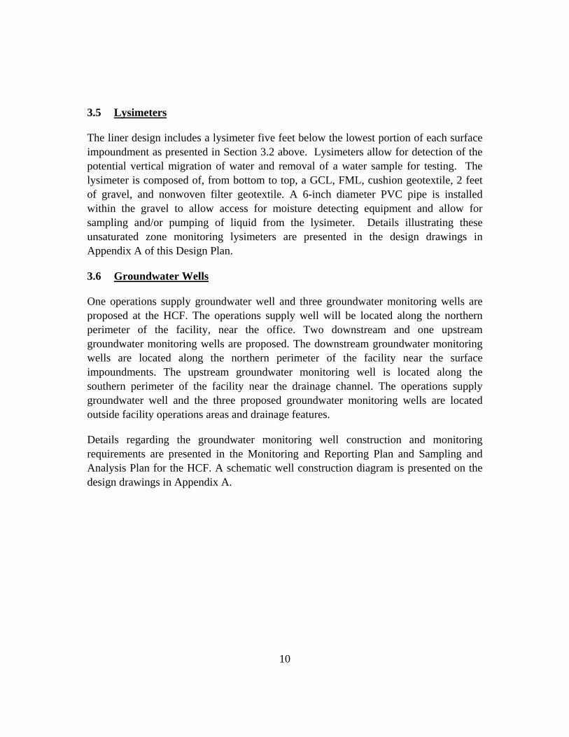
Three openings are incorporated into the surface impoundment diversion berm to direct the peak discharge from the 100-year, 24-hour storm event from the remainder of the Site into the surface impoundments. Calculations to size the openings length for flow through during the 100-year, 24-hour storm event are presented in Appendix C. A 20-foot opening is incorporated in the diversion berm south of Surface Impoundment A and two 10-foot openings are incorporated in the diversion berm to the east and south of Surface Impoundment B. The openings are designed with concrete abutment walls on each side of the inlet, intermediate bollards set at 10-foot increments, and concrete aprons upstream and downstream of the inlet to control erosion. The upstream portion of the apron has a thickened edge extending 12 inches below grade to control erosion. In addition, a metal plate is bolted to the downstream portion of the concrete apron to bridge the gap between the concrete apron an the lined surface impoundment.
During typical operating conditions, the openings will remain open for water to sheet flow into the impoundments. Anytime the water in the surface impoundments approaches the minimum required two feet of freeboard, the openings will be closed by manually inserting long stop logs made of metal (i.e. aluminum or stainless steel), or engineer-approved alternative material into guide frames attached to the concrete abutments, and intermediate bollards on the sides of the openings, and the concrete apron on the bottom of the openings. The stop logs shall be made of one piece in the longitudinal direction across the diversion berm opening (nominally 10-feet), but are typically constructed in segments in the vertical direction to facilitate manual insertion. The stop logs will incorporate a rubber, neoprene, or engineer-approved equivalent seal on each side (end) to seal at the wall and across the bottom to seal at the sill or with the next log. The top elevation of the stop logs will be at least as high as the top elevation of the diversion berms. The stop logs will be stored in a designated, fully marked location onsite at the office. When the stop logs are in place, the stormwater from events in excess of the 100-year, 24-hour, storm event will back up onto the northern end of the Site (“1,000 year storm event containment area”).
The 1,000-year, 24-hour hydrology study prepared by AEI CASC is presented in Appendix B of this Deisgn Plan (AEI CASC, 2011). The Site design grades and

9
consideration of other site features in the area (office trailer, vehicle parking, tanks, and compost) were used to determine the 1,000 year storm event containment area while the stoplogs are in place. The office trailer is elevated and will not impact the 1,000 year storm event containment area. Vehicles and onsite equipment displace a minimal stormwater volume and would be relocated out of the 1,000 year storm event containment area during such events. Tanks will be located outside of the 1,000 year storm event containment area. When the facility is operating at full capacity, there will be an estimated 3,000 cubic yards of compost within the 1,000 year storm event containment area which is equivalent to approximately 1.8 acre-feet. Approximately 0.9 acre-foot of compost volume (volume that would be within the depth of stormwater) was included for the east and the west sides of the Site in the net stormwater volume in the AEI CASC study to determine the limits of the 1,000 year storm event containment area.
The net volume difference between the 100-year, 24-hour and the 1,000-year, 24-hour storm events plus the contributing volume from the other site features is 5.3 acre-feet (AF) for the On-Site Area A (14.9 AF + 0.9 AF – 10.5 AF) and 3.6 AF (9.2 AF + 0.9 AF – 6.5 AF) for On-Site Area B. These On-Site Areas are the drainage areas to the Surface Impoundments A and B, respectively. To contain the net stormwater volume from a 1,000-year 24-hour precipitation event on the Site, the minimum elevation of the perimeter berm and the surface impoundment diversion berm is 2,317.6 feet for the western portion of the facility draining to Surface Impoundment A, and 2,318.7 feet for the eastern portion of the facility draining to Surface Impoundment B.
3.4 Leak Detection Monitoring Sumps
The HCF design includes a leak detection monitoring sump (LDMS) below the lowest portion of each surface impoundment as presented in Section 3.2 above. The LDMS allows for detection of the potential vertical migration of water and removal of a water sample for testing. The LDMS is composed of, from bottom to top, a GCL, a FML, cushion geotextile, 2 feet of gravel, and nonwoven filter geotextile. A 6-inch diameter PVC pipe is installed within the gravel to allow access for moisture detecting equipment and to allow for sampling and/or pumping of liquid from the LDMS. Details illustrating these sumps are presented in the design drawings in Appendix A of this Design Plan.
10
3.5 Lysimeters
The liner design includes a lysimeter five feet below the lowest portion of each surface impoundment as presented in Section 3.2 above. Lysimeters allow for detection of the potential vertical migration of water and removal of a water sample for testing. The lysimeter is composed of, from bottom to top, a GCL, FML, cushion geotextile, 2 feet of gravel, and nonwoven filter geotextile. A 6-inch diameter PVC pipe is installed within the gravel to allow access for moisture detecting equipment and allow for sampling and/or pumping of liquid from the lysimeter. Details illustrating these unsaturated zone monitoring lysimeters are presented in the design drawings in Appendix A of this Design Plan.
3.6 Groundwater Wells
One operations supply groundwater well and three groundwater monitoring wells are proposed at the HCF. The operations supply well will be located along the northern perimeter of the facility, near the office. Two downstream and one upstream groundwater monitoring wells are proposed. The downstream groundwater monitoring wells are located along the northern perimeter of the facility near the surface impoundments. The upstream groundwater monitoring well is located along the southern perimeter of the facility near the drainage channel. The operations supply groundwater well and the three proposed groundwater monitoring wells are located outside facility operations areas and drainage features.
Details regarding the groundwater monitoring well construction and monitoring requirements are presented in the Monitoring and Reporting Plan and Sampling and Analysis Plan for the HCF. A schematic well construction diagram is presented on the design drawings in Appendix A.


SURFACE IMPOUNDMENT PERIMETER ANCHORAGE
WASTE PILE
COMPOSTING AREA
LINING SYSTEM
SURFACE IMPOUNDMENT
LINING SYSTEM
RETENTION BASIN BOTTOM
ANCHOR TRENCH
SURFACE IMPOUNDMENT - TYPICAL SECTION
RETENTION BASIN BOTTOM ANCHORAGE
GROUNDWATER MONITORING WELL
(SHOWN AT DIVERSION BERM OPENING)

IH
J
NM
K

(MIN.)
20' (MIN.)
1'
2:1
2:1
20' (MIN.)
8"
1'
4"
12"
3:1 3:1
5'
TYP.
NOTES:
1. THE STOP LOGS SHALL BE OF ONE PIECE (LONGITUDINALLY ACROSS THE OPENING) AND SHALL
HAVE A WIDTH OF 10'. THE STOP LOGS MAY CONSIST OF MULTIPLE PIECES VERTICALLY, PER
STANDARD MANUFACTURERS DIMENSIONS. THE STOP LOGS SHALL BE FABRICATED OF METAL OR
ENGINEER APPROVED EQUIVALENT (I.E. COPOLYMER COMPOSITE).
2. THE STOP LOGS SHALL BE MANUALLY INSERTED AND REMOVED INTO A GUIDE AND FRAME
ASSEMBLY FABRICATED OF METAL (I.E., CAST IRON, STEEL, OR ALUMINUM) OR ENGINEER
APPROVED EQUIVALENT AND MUST BE COMPATIBLE WITH THE STOP LOG MATERIAL SELECTED.
3. THE GUIDE FRAMES SHALL BE EMBEDDED IN THE CONCRETE APRON AND ABUTMENT WALLS. THE
STOP LOG GUIDE FRAMES SHALL BE BOLTED, PER MANUFACTURERS SPECIFICATIONS, TO
MINIMUM 8"X8" (PLAN) CONCRETE FILLED STEEL BOLLARDS.
4. THE BOTTOM OF THE STOP LOGS SHALL PROVIDE A FLUSH SEAL ALONG THE GUIDE FRAME
SURFACES TO PROVIDE A PROPER SEAL AT THE STOP LOG CONTACT SURFACES AND AT THE
CORNERS. THE TOP OF THE STOP LOGS SHALL BE FLUSH WITH OR EXTEND ABOVE THE TOP OF
THE ADJACENT BERM. CONTRACTOR MAY PROPOSE EQUIVALENT GUIDE FRAMES AND SEALS,
SUBJECT TO ENGINEER APPROVAL.
5. THE BOLLARD AND ABUTMENT FOUNDATIONS SHALL BE AT LEAST 6 INCHES WIDER THAN THE
ABOVE GRADE DIMENSIONS EACH WAY AND SHOULD EXTEND 2 FEET BELOW GRADE.
6. APRON SHALL CONSIST OF 4-INCH THICK CONCRETE REINFORCED WITH 6X6-W1.4XW1.4 WELDED
WIRE MESH ON EITHER SIDE OF THE STOP LOG EMBEDDED SILL. THE APRON SHALL HAVE A 12" DEEP
THICKENED EDGE ON THE UPSTREAM SIDE.
7. CONCRETE SHALL HAVE A 28-DAY COMPRESSIVE STRENGTH OF 3,000 PSI. CONCRETE
ABUTMENTS SHALL BE REINFORCED WITH #5 BARS @ 12"O.C. EACH WAY WITH 2" CLEAR COVER.
8. FILL AND SUBGRADE SHALL BE COMPACTED TO A MINIMUM OF 90% RELATIVE COMPACTION USING
ASTM D 1557 AS THE COMPACTION STANDARD.
TYPICAL DETAIL
SURFACE IMPOUNDMENT STORMWATER
DIVERSION BERM OPENING (PLAN VIEW)
DETAIL (TYPICAL)
DIVERSION BERM ABUTMENT
(PLAN VIEW)
DETAIL (TYPICAL)
BOTTOM STOP LOG EMBEDDED
GUIDE FRAME (CONCRETE APRON )
DETAIL (TYPICAL)
SIDE STOP LOG EMBEDDED GUIDE
FRAME (ABUTMENTS)
DETAIL
SIMULATED CHECK SLOT
DETAIL
KEY TRENCH AT TOP OF SLOPE
DETAIL
PERMANENT TURF
REINFORCEMENT MAT
DETAIL
TURF REINFORCEMENT
MAT OVERLAP JOINT
DETAIL
ANCHOR PIN
DETAIL
ANCHOR PATTERN
DETAIL
TERMINATION AT TOE OF SLOPE
DETAIL
ANCHOR TRENCH AT TOE OF SLOPE
4' MIN.
12"
12"
REINFORCED CONCRETE
(SEE NOTE 7)
DETAIL (TYPICAL)
SIDE STOP LOG MOUNTED GUIDE
FRAME (BOLLARDS)
TYPICAL SECTION
SURFACE IMPOUNDMENT STORMWATER
DIVERSION BERM OPENING


