Norwegian Mapping Authority Hydrographic Service
MAREANO programme
Page 1 of 19 Appendix B – Technical specifications
Norwegian Hydrographic Service
and
…
APPENDIX B
Technical Specifications
MAREANO Programme
11.12.2017
Some changes are made in this updated MAREANO specification dated 11 December 2017. The changes are
basically related to echosounder specifications, sound velocity and absorption coefficient profiles, backscatter
and sub bottom profiler requirements. Some additional minor changes are also made.
Norwegian Mapping Authority Hydrographic Service
MAREANO programme
Page 2 of 19 Appendix B – Technical specifications
Technical Specifications
Table of content:
1 Overview ............................................................................................................................................ 3 2 Terms and Definitions ........................................................................................................................ 4 3 Abbreviations ..................................................................................................................................... 5 4 Informal description of the data product ............................................................................................ 5
5 Equipment Requirements ................................................................................................................... 5 6 Reference Systems ........................................................................................................................... 87 7 Data Quality Requirements ................................................................................................................ 8
7.1 Resolution .................................................................................................................................... 8 7.2 Accuracy requirements ................................................................................................................ 8
7.2.1 Horizontal accuracy requirement ......................................................................................... 8
7.2.2 Overall vertical accuracy requirement ................................................................................. 8 7.2.3 Vertical precision (consistency) requirement ..................................................................... 98
7.3 Accuracy verification ................................................................................................................ 98 7.3.1 Verification area survey ..................................................................................................... 98 7.3.2 Main survey consistency check ............................................................................................ 9
7.4 THU and TVU ......................................................................................................................... 109 7.5 Timing ....................................................................................................................................... 10 7.6 Data gaps ................................................................................................................................... 10
7.7 Backscatter data ......................................................................................................................... 11 7.8 Sub-bottom profiler data ....................................................................................................... 1211
7.8.1 Requirements for sub-bottom profiler data collection ....................................................... 12 8 Survey control .................................................................................................................................. 12
8.1 Calibration and verification ....................................................................................................... 12
8.1.1 Survey vessel reference frame ............................................................................................ 13
8.1.2 Sensor Alignment ........................................................................................................... 1413 8.1.3 Sensor Calibration .............................................................................................................. 14
8.2 Field verification ....................................................................................................................... 14 8.3 Crosslines and line overlap ....................................................................................................... 14
8.4 Survey area and line planning ............................................................................................... 1514 8.5 Reports ...................................................................................................................................... 15
9 Bathymetric data processing ........................................................................................................ 1615 10 Data product delivery ..................................................................................................................... 16 11 Metadata ......................................................................................................................................... 18
12 Data storage .................................................................................................................................... 18 13 Support ........................................................................................................................................... 18 14 Operation manual ........................................................................................................................... 18 15 References .................................................................................................................................. 1918
Norwegian Mapping Authority Hydrographic Service
MAREANO programme
Page 3 of 19 Appendix B – Technical specifications
1 Overview This specification gives the requirements for data to be used in the MAREANO programme. In
addition to product specifications, some equipment and procedure requirements are also presented.
Title: Specifications for Seabed Mapping within the MAREANO programme
Date: 2016.12.14
Responsible party: Norwegian Mapping Authority, Hydrographic Service (NHS)
P.O. Box 60
N-4001 Stavanger
NORWAY
Phone: +47-51858700
Fax: +47-51858701
E-mail: [email protected]
URL: http://www.sjokart.no
http://www.mareano.no
Language: English
Distribution format: PDF
Norwegian Mapping Authority Hydrographic Service
MAREANO programme
Page 4 of 19 Appendix B – Technical specifications
2 Terms and Definitions Calibration
Calibrations comprise both the determination of corrections and the use of these corrections.
Complete Dataset
A complete dataset consists of hydrographic data satisfying data coverage requirements in terms of
total area, survey area limits, sounding density and restrictions on data gaps.
Field Verification
A field verification of the survey spread calibration is based on analysing overlapping hydrographic
data collected in a small area with suitable seabed characteristics. The survey pattern is selected in a
way that any calibration error is as visible as possible.
Hydrographic Data
All data gathered during the survey and all the related metadata required for seabed mapping.
Mobilisation and Demobilisation
This includes all activity related to preparation and survey spread setup and dismounting.
The mobilisation is not considered completed until Client has approved the documentation of all
calibration and verification activity as described in Section 8.1.
Survey area limit
A closed polygon that surround all measured and QC data in a project. Under certain instances,
several limits may be needed.
Survey spread
This includes the survey vessel itself and all the equipment required to perform the survey.
Survey vessel reference frame
This is an orthogonal coordinate system with a fixed position and orientation relative to the survey
vessel hull.
Verification
Verification determines if a system or a sensor operates within specifications.
Unambiguous dataset
This indicates that every position on the seabed is assigned only one unique depth.
XYZ-data
The term XYZ- data is used to describe georeferenced individual soundings from the MBES.
Norwegian Mapping Authority Hydrographic Service
MAREANO programme
Page 5 of 19 Appendix B – Technical specifications
3 Abbreviations EUREF89 Is the same as the European Terrestrial Reference Frame 1989 (ETRF89)
GNSS Global Navigation Satellite Systems
IERS International Earth rotation and Reference system Service
IGS International GNSS Service
IHO International Hydrographic Organisation
ITRF International Terrestrial Reference Frame
MBES Multibeam Echosounder
MSL Mean Sea Level
MVP Moving Vessel Profiler (used for "continuous" sound velocity or CTD observations)
NGU The Geological Survey of Norway
NHS The Norwegian Hydrographic Service
OM Operation Manual
QC Quality Control
SVP Sound Velocity Profile
THU Total Horizontal Uncertainty (defined in IHO-S44)
TVU Total Vertical Uncertainty (defined in IHO-S44)
4 Informal description of the data product The Contractor shall deliver complete and unambiguous hydrographic data having the desired
accuracy, collected with multibeam echo sounder (MBES) at its highest resolution mode.
In addition to the general seabed topography, all seabed features (like iceberg scour marks, coral
reefs, pockmarks, sand waves and boulders, etc.) are very important to the MAREANO programme.
Both the survey and the processing shall be carefully done to preserve all the seabed feature
information and removing all the faulty soundings. Seabed features shall not be camouflaged by
artefacts and artefacts must not appear as seabed features. No smoothing of the XYZ data shall be
applied. Backscatter data are equally important as bathymetry data for the MAREANO programme.
The multibeam backscatter data shall provide a representative view of natural variations in seabed
acoustic reflectivity within the survey area, such that they are suitable for geological mapping.
5 Equipment Requirements Positioning
The GNSS antenna positioning uncertainty shall be within 0.3m (95%) for the horizontal component
and within 0.1 m (95%) for the vertical component. Post processing of positioning is accepted. The
positioning shall be based on a high- quality dual frequency GNSS receiver and a high- quality
calibrated GNSS antenna type. All the raw data shall be stored for post processing.
Norwegian Mapping Authority Hydrographic Service
MAREANO programme
Page 6 of 19 Appendix B – Technical specifications
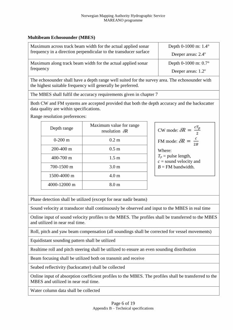
Multibeam Echosounder (MBES)
Maximum across track beam width for the actual applied sonar
frequency in a direction perpendicular to the transducer surface
Depth 0-1000 m: 1.4°
Deeper areas: 2.4
Maximum along track beam width for the actual applied sonar
frequency
Depth 0-1000 m: 0.7°
Deeper areas: 1.2
The echosounder shall have a depth range well suited for the survey area. The echosounder with
the highest suitable frequency will generally be preferred.
The MBES shall fulfil the accuracy requirements given in chapter 7
Both CW and FM systems are accepted provided that both the depth accuracy and the backscatter
data quality are within specifications.
Range resolution preferences:
Depth range Maximum value for range
resolution R
0-200 m 0.2 m
200-400 m 0.5 m
400-700 m 1.5 m
700-1500 m 3.0 m
1500-4000 m 4.0 m
4000-12000 m 8.0 m
Phase detection shall be utilized (except for near nadir beams)
Sound velocity at transducer shall continuously be observed and input to the MBES in real time
Online input of sound velocity profiles to the MBES. The profiles shall be transferred to the MBES
and utilized in near real time.
Roll, pitch and yaw beam compensation (all soundings shall be corrected for vessel movements)
Equidistant sounding pattern shall be utilized
Realtime roll and pitch steering shall be utilized to ensure an even sounding distribution
Beam focusing shall be utilized both on transmit and receive
Seabed reflectivity (backscatter) shall be collected
Online input of absorption coefficient profiles to the MBES. The profiles shall be transferred to the
MBES and utilized in near real time.
Water column data shall be collected
CW mode: 𝑅 = 𝑐𝑇𝑝
2
FM mode: 𝑅 = 𝑐
2𝐵
Where:
Tp = pulse length,
c = sound velocity and
B = FM bandwidth.
Norwegian Mapping Authority Hydrographic Service
MAREANO programme
Page 7 of 19 Appendix B – Technical specifications
Sediment echosounder
Minimum recording window below seafloor 200 ms TWT
Maximum frequency (shipborne system) 20 kHz
Minimum frequency (shipborne system) 2.5 kHz
Delay time change Manual
Roll, pitch and yaw compensation/recording All soundings shall be corrected for vessel motions
Attitude and heading sensor
The sensor requirements are:
Heading (GNSS based) 0.05° RMS
Roll and Pitch 0.02° RMS
Heave 0.05 m or 5% of amplitude
Output rate Min. 100 Hz
The Heading shall be GNSS-based or GNSS-aided. Heading purely based on inertial sensors is not
accepted. Post processed heave is accepted.
Sound Velocity and Absorption Coefficient profiles
The time between measured profiles shall not exceed two hours. Profiles to the full survey depth
shall be made at least once every 6 hours. The rest of the profiles may be made to shallower depths
only where the deeper layers show insignificant sound velocity variations. The profiles shall have a
good spatial, as well as temporal coverage of the oceanographic conditions. There must be sufficient
deep profiles in deeper areas to provide good corrections for these areas and deep profiles shall be
used for shallow profile extension. All profiles must be visually inspected before they are used.
Action must be taken to identify sound velocity challenges specific to the area and to acquire enough
SVP profiles to sufficiently represent the spatio-temporal variations.
The equipment shall preferably be a CTD sensor but a carbon fibre based "sing-around" sound
velocity + temperature sensor will also be accepted. The sensor requirements are:
Temperature 0.01°C RMS
Sound velocity 0.05 m/s RMS
Depth range, full scale 0.05% RMS
Profiles of absorption coefficient shall be calculated from the measured CTD profiles. E.g. the input
of a single salinity value is not accepted. The profiles shall be calculated and applied without
significant delay, and logging of a new line shall be started. Manual adjustments during logging shall
not be made.
Norwegian Mapping Authority Hydrographic Service
MAREANO programme
Page 8 of 19 Appendix B – Technical specifications
Formulas for calculations from measured CTD:
The formula from [Chen and Millero] or [Del Grosso] shall be used for calculation of sound speed.
Formula from [Francois and Garrison] shall be used for absorption coefficient calculation.
Sound velocity at transducer head
The sound velocity shall continuously be measured close to the sonar head(s) and automatically be
applied by the MBES. This sensor shall utilize "sing around" sound velocity observations over a
carbon fibre distance base. Accuracy requirements are the same as for the sound velocity profiles.
6 Reference Systems Horizontal
The horizontal reference system for all the data shall be EUREF89. ITRF positions must be
transformed to EUREF89. The transformation formulas shall be approved by the Client.
Vertical
All depths shall be given as ellipsoidal depths in the EUREF89 datum.
Timing
All registrations of time shall be given in Co-ordinated Universal Time (UTC).
7 Data Quality Requirements
7.1 Resolution
The beam angle from nadir shall not exceed 60°. For deep areas where the echosounder range is the
limiting parameter, the swath width shall be reduced to obtain good data on the outer beams. This
gives the densest possible coverage within the maximum available swath width.
The sounding distance (both along track and across track) shall not exceed 2*depth*tan(60)/399.
The along track sounding distance shall not significantly exceed the across track sounding distance.
7.2 Accuracy requirements
General information about the requirements: 1. The requirements only apply for accepted data. 2. The requirements apply for all the accepted data (not 95%) 3. Every accepted sounding shall fulfil all the specified requirements. 4. Accuracy limits scale with depth. The depth used in the formulas below, is the vertical distance
between the mean sea level and the seabed.
7.2.1 Horizontal accuracy requirement
The horizontal position of the soundings on the seabed shall be within ±(0.5m + 0.016*depth) from
the correct value.
7.2.2 Overall vertical accuracy requirement
All accepted soundings shall be within the vertical distance of ±(0.25m + 0.004*depth) from the
correct value.
Norwegian Mapping Authority Hydrographic Service
MAREANO programme
Page 9 of 19 Appendix B – Technical specifications
7.2.3 Vertical precision (consistency) requirement
The vertical precision (as defined in section 7.3.27.3.2) shall be within 0.2m + 0.004*depth.
The vertical precision is a point-to-point total depth difference and not a ± value.
7.3 Accuracy verification
The accuracy of the soundings will be checked in two steps
1. Verification area survey 2. Main survey consistency check
7.3.1 Verification area survey
Minimum one verification area shall be surveyed prior to the main survey. This area shall be an
existing well-surveyed area with an already established reference surface.
Data from the verification survey shall be processed, and the accepted soundings will be compared to
the existing reference surface.
The verification survey is used to check both the overall vertical accuracy (section 7.2.2) and the
horizontal accuracy (section 7.2.1). Data acquisition in the verification area shall include backscatter,
water column data and data from any other instrument which will be operated during the course of
the survey. All data from the verification survey shall be delivered prior to the start of the main
survey. These data will be checked as early as possible, preferably before the main survey starts.
7.3.2 Main survey consistency check
The internal consistency of the main survey is checked by comparing overlapping lines and
neighbouring soundings. It is a measure of how well the overlapping lines and neighbouring
soundings fit together. In this specification the vertical precision is defined as the vertical distance
between neighbouring soundings. Physical terrain variations over the horizontal distance between the
soundings must be considered and should ideally not be a part of this difference. This fact gives
room for some subjective judgements regarding the measured depth differences.
Figure 2 The tools used by NHS determines the
vertical precision from the point-to-point
variations (red line). Some allowance for real
terrain variations must be added.
Figure 1 The overlap between two survey lines
shows a depth difference between the two lines.
In this example the vertical precision is the
same as the difference in depth level between
the lines.
Formatert: Engelsk (Storbritannia)
Norwegian Mapping Authority Hydrographic Service
MAREANO programme
Page 10 of 19 Appendix B – Technical specifications
The overlapping areas between lines and neighbouring data will be used to check the vertical
precision (section 7.2.3).
Seabed features in overlapping areas will be used to check the horizontal accuracy (section 7.2.1).
7.4 THU and TVU
The 95% THU and TVU values as defined by IHO shall be calculated and reported for all soundings.
These values shall be calculated from the best available knowledge about the survey system. No
parameters shall be adjusted to fit the values to the specified requirements. The reported THU and
TVU values will not be used for data rejection.
7.5 Timing
All data are to be time-stamped to UTC within 1ms (95%).
The Contractor shall read and timestamp all sensor data, and the Contractor is urged to document the
timestamp uncertainty. Preferably all survey data (observations) shall be time stamped at source.
7.6 Data gaps
Data gaps are caused by missing soundings or by soundings rejected in the data processing. The
accepted bathymetry data shall be checked for data gaps by defining a data gap grid (DGG). The
DGG grid size is 2.5 times the nominal sounding distance.
Depth [m]
Relative MSL
Nominal abeam
sounding distance[m]
DGG grid
size
3-10 0,1 0,5
10-20 0,2 0,7
20-40 0,4 1,0
40-70 0,6 1,5
70-100 0,9 2,5
100-200 1,7 4,5
200-300 2,6 6,5
300-400 3,5 8.5
400-500 4,3 11,0
500-600 5,2 13,0
600-700 6,1 15.0
700-800 7,0 17.0
800-900 7,8 19,5
900-1000 8,7 21,5
3300-3400 29,5 73,5
3400-3500 30,4 76,0
A DGG cell with less than 4 accepted
soundings is defined as a gap
More than five adjacent DGG gap-cells
are not accepted
Norwegian Mapping Authority Hydrographic Service
MAREANO programme
Page 11 of 19 Appendix B – Technical specifications
A DGG cell with less than 4 accepted soundings is defined as a gap.
More than five adjacent (i.e. cells sharing one side) DGG gap-cells are not accepted, unless the area
is without significant topographical details. In areas with no significant topographical details, a
maximum of two subsequently missing pings are accepted. Inter-ping gaps due to yaw
compensation, are also accepted in such areas. The total number of gaps shall, however, not exceed
0.1% of the DGG cells.
7.7 Backscatter data
High resolution, georeferenced backscatter data shall be collected to provide information on seabed
acoustic reflectivity, which is required by MAREANO for geological mapping purposes. Note that
that backscatter data quality is often independent of the bathymetry data quality and must be checked
regularly to ensure that it provides a representative view of the natural variations in the acoustic
reflectivity of the seabed. Data are considered unusable where they are dominated by noise or other
artefacts. Unusable backscatter data is not acceptable for MAREANO, just as data gaps are not
acceptable for bathymetry data (section 7.6).
The Contractor shall take all necessary measures to obtain the best possible backscatter data quality
and shall be familiar with the guidelines and recommendations provided by the GeoHab backscatter
working group (Lurton and Lamarche, 2015), in particular Chapter 5 Acquisition: best practice
guide. Further to this, the Contractor shall follow the guidelines below:
For multi-sector MBES the echosounder must be sector calibrated prior to mobilisation
and the MBES data shall be backscatter normalised upon delivery.
Good quality backscatter data shall be acquired for the entire survey area. Missing data,
or data of unusable quality shall not exceed 1% of the total area of each survey block.
Backscatter data are generally more sensitive to bad weather than bathymetry data.
Survey speed and/or line direction should be adapted to obtain the best possible data and
the survey suspended if many missing or bad pings are visible in the backscatter data.
The backscatter data quality shall be monitored continuously during data acquisition, and
backscatter mosaics of each survey block shall be routinely produced onboard for QC
purposes (5 m resolution or finer in depths shallower than 500 m; 10 m resolution or finer
in depths of 500-1200 m). No cosmetic levelling of dB values shall be applied to these
mosaics. The contractor shall endeavour to avoid multibeam receiver acoustic saturation
of the backscatter data. Any depth or noise filters applied should not have a detrimental
effect on the backscatter data quality, nor cause irretrievable loss of data.
The Contractor shall ensure that systematic variations to backscatter intensity are kept to
a minimum and shall avoid the use of automatic acquisition settings as these cause
problems for backscatter data processing and interpretation. This includes application of
valid absorption coefficients at all times. All real-time acquisition parameters required to
conduct post processing shall be included with the digital logged data. It is important that
changes in settings for gain, pulse length, frequency, or any other system changes are
minimised.
Norwegian Mapping Authority Hydrographic Service
MAREANO programme
Page 12 of 19 Appendix B – Technical specifications
Where changes to acquisition settings are unavoidable across the survey area due to
bathymetric mapping requirements, the survey should be split into contiguous sub-areas
(blocks) with consistent settings. These considerations should be taken into account at the
survey planning stage (see section 8.4). Minor adjustments may be accommodated by
starting logging of a new line any time changes to acquisition settings are made.
If more than one MBES and/or survey vessel is used within a survey block then at least
one line with 100% overlap should be logged, where acquisition is conducted in the same
direction to provide a reference line for backscatter interpretation.
7.8 Sub-bottom profiler data
Sub-bottom profiler data are essential for mapping bottom types, sedimentary environments and
processes on the seabed and below the seabed. Names commonly used for sub-bottom profiler are
chirp, pinger, sediment echosounder and high resolution seismic. Sub-bottom profiler data should be
collected during the multibeam echosounder mapping cruises.
7.8.1 Requirements for sub-bottom profiler data collection
Sub-bottom profiling should start (line 1) along one of the boundaries of the area to be
mapped.
Internal distance between sub-bottom profiler lines should not exceed 10 km.
After this, if more than 5 km remains to the other boundary of the mapping area, a last line
should be run along that boundary.
Straight lines are preferred, but curved lines are accepted if this is necessary to optimize
acquisition of bathymetric data.
The ping rate should be as high as possible, but the recording window below the seafloor
should not be less than 0.2 seconds two-way time (TWT). Maximum ping intervals:
o 0.5 second for water depths shallower than 500 m
o 1 second for water depths of 500 m and deeper.
Vertical data resolution should be at least 10 cm for 0-50 m, 20 cm for 50-100 m, 30 cm for
100-500 m, 40 cm for 500-1000 m, 50 cm for 1000-1500 m, and 100 cm for deeper waters.
8 Survey control The Contractor shall document that all requirements given in this specification have been met. The
Contractor shall continuously carry out Quality Control during data collection and processing. The
Client shall have access to these procedures.
Any modification of the survey spread shall be documented and reported to the Client.
New equipment shall have the same or better quality as replaced equipment. Introduction of new
vessels during the project may be accepted. This will, however, require a full documentation of the
equipment and the vessel. The vessel survey report must be accepted by the Client before the new
vessel is put into use.
8.1 Calibration and verification
The calibration and verification delivery (reports and data files) shall contain all the required
information for a third party to verify the results. The uncertainty of the calibration and verification
results shall be documented.
Norwegian Mapping Authority Hydrographic Service
MAREANO programme
Page 13 of 19 Appendix B – Technical specifications
The Contractor is responsible for maintaining and documenting the total system performance during
the survey. This shall be obtained by calibration and verification.
A verification of all determined calibration parameters is required before the parameters are put into
use. This shall be part of the calibration and verification procedure.
Calibration of all equipment in the survey spread
The Contractor shall conduct a calibration of the total survey spread.
The Calibrations shall include but not be limited to:
Post-installation calibration:
Initial determination of system parameters (e.g. position and orientation of new sensors
relative to the Body reference frame)
Scheduled calibrations:
This comprises both laboratory calibration of instruments according to service interval
requirements, and onboard calibration of composite systems
Calibration after incidents or after equipment configuration changes:
This comprises the calibration of all equipment affected by an incident, as well as calibration
after remounting or replacement of essential parts of a system.
8.1.1 Survey vessel reference frame
A reference frame shall be defined for the survey vessel.
A sufficient number of permanently marked points shall be established at suitable locations on the
vessel. All points intended for GNSS antenna mounting (e.g. marked by a drilled hole for the antenna
attachment bolt) shall be surveyed (it is not sufficient to only survey the antenna itself). Surface
vessels shall additionally have a minimum of 4 dedicated GNSS antenna mounts permanently
marked in suitable locations for attitude sensor calibration.
Every sensor outputting data sensitive to sensor position or sensor installation angles shall have these
values determined in the survey vessel reference frame.
Sensor positions as well as sensor installation angles shall (as a minimum) be determined to the
accuracy level specified in the equipment installation manual. The position and installation angle
accuracy requirements for every system component must be carefully judged, so that the accuracy of
the final product is kept within the specified range.
The uncertainty of all surveyed reference points on the vessel must be sufficient to satisfy the
accuracy requirement related to the use of the points (i.e. often related to sensor calibration
requirements).
The installation survey report shall contain a full description of the survey and a clear presentation of
the results. The procedure for the determination of sensor position and installation angles, as well as
the uncertainty of the determined values, shall be well documented.
The installation survey delivery shall include the report and the digital observation files. This
delivery shall contain all the required information for a third party to verify the results. An example
of such a report can be found in “Info_B_alignment_report.pdf”.
Norwegian Mapping Authority Hydrographic Service
MAREANO programme
Page 14 of 19 Appendix B – Technical specifications
8.1.2 Sensor Alignment
Multibeam Echosounder
The MBES transducer installation angles shall be determined by a land-survey operation to obtain a
sufficient connection to the survey vessel reference frame.
Attitude and Heading sensors
Attitude sensors shall be mounted on a rigid, machined surface with steering pins to ensure
repeatable precision mounting.
The determination of vessel motion sensor and heading sensor installation angles shall be by use of
at least four (preferably more) GNSS antennas, to obtain a time series of the “true” orientation of the
survey vessel. During calibration, the vessel shall manoeuvre to obtain realistic attitude sensor
behaviour. Installation angles are determined from the difference between the GNSS derived attitude
values and the attitude sensor readings. Alternative methods will be accepted if they are documented
to give better results.
Positioning sensor
GNSS antenna calibration values from the IGS shall be utilized.
Examples of sensor alignment are given in “Info_B_alignment_report.pdf”.
8.1.3 Sensor Calibration
All equipment requiring regular calibrations against standards shall hold a valid calibration
certificate from a certified institution. The equipment shall be maintained and handled according to
manufacturer’s recommendations to make it plausible that the equipment is kept within its accuracy
specifications between calibrations.
The Contractor shall keep a historical record of all calibration and verification results for all
equipment at the serial number level.
8.2 Field verification
The continued validity of the survey spread must be confirmed at relevant intervals during each
survey season. Verification schedules shall be presented as a part of the tender. A new Field
Verification is required after any modification or reconfiguration of the survey spread.
If the verification determines discrepancies of the installation parameters, additional calibration of
the system is required.
As part of the survey mobilisation, the Contractor shall perform a Field Verification to document that
the complete survey spread with all equipment systems operates within specifications. This test shall
be performed in an area specified by Client.
8.3 Crosslines and line overlap
Survey line overlap
There shall be at least 10% overlap between survey lines (a new line shall cover 10% of the
preceding line).
Crosslines
Norwegian Mapping Authority Hydrographic Service
MAREANO programme
Page 15 of 19 Appendix B – Technical specifications
There shall be at least one crossline for every sub-survey area. If the sub- survey area size exceeds
500 km2, there shall be one crossline per 500 km2. Crosslines may be planned in connection with
crew change or infill lines. The crosslines may be split into several parts. Crossline (or crossline
segments) shall cover the sub survey area from one side to the other in a direction between 70° and
90° from the ordinary survey direction.
8.4 Survey area and line planning
The total survey area shall be split into sub-areas (blocks), where data from each of which is
considered a sub-delivery. Division of the blocks has particular implications for backscatter data as it
is this dataset which is most sensitive to changes in acquisition settings which typically need to be
changed with depth (gain, pulse length, frequency).
The following points should be followed as far as practically possible during survey planning:
Blocks should be as large as is practically possible (typically in the range 500-2000 km2)
Blocks need not have a regular geometry, but will rather follow depth contours allowing
consistent acquisition settings and a single MBES and vessel to be used within each block.
8.5 Reports
All reports shall be sent by e-mail to a mailing list provided by the Client.
Daily reports during survey
These are very brief reports indicating daily problems and progress.
Weekly reports during survey
More comprehensive (but still brief) reports indicating survey progress and status related to
schedule.
The report shall contain
The estimated survey completion date
The surveyed area [km2] and a plot showing the area.
Processing and QC progress and status related to schedule
The estimated final delivery date
Weekly processing reports after survey
Brief reports indicating processing and QC progress and status related to schedule. The report shall
include the estimated completion date. Processing reports are requested during the time from survey
completion until the data are accepted.
Final report
A final survey report shall be delivered as a part of the documentation. This report is the Contractors
summary of the survey, and shall contain documentation of all hydrographical data, data processing,
interpretation and information of data quality.
The report shall as a minimum contain:
Data collection method and their technical specifications and comments on the processes
Geodetic reference system, positioning-methods and their error budgets
Date and time for the data collection
All corrections applied to the data and details of Quality Control Procedures
Norwegian Mapping Authority Hydrographic Service
MAREANO programme
Page 16 of 19 Appendix B – Technical specifications
Estimates of random and systematic errors concerning the data
Other data referred to in IHO S44, Chapter 5
Experiences, comments and findings
Processing parameters should be included digitally together with the project data, or be included in
the final survey report.
The final survey report shall be submitted to the Client no later than three weeks after the completion
of the quality controlled data set.
Executive summary report
Following all data deliverables, an executive summary report shall be delivered. A template for an
Executive Summary Report can be found in Info_A_Executive Summary_template.doc
9 Bathymetric data processing Careful processing is required to obtain the specified data quality.
The processing shall focus on removing all faulty soundings at the same time as the seabed feature
information is preserved.
Artefacts in the processed XYZ- data shall be kept at an insignificant level not disturbing the seabed
image.
Faulty soundings shall be flagged as rejected, and no soundings shall be deleted.
XYZ-data shall not be smoothed.
10 Data product delivery All data related to a survey block shall be delivered, including data outside the block limit.
Data types:
Accepted bathymetry XYZ-data (observed data)
Rejected bathymetry XYZ-data (observed data)
Horizontal and vertical uncertainty for each depth value (THU and TVU)
Survey area limits generated from accepted data
Preliminary bathymetry grids based on roughly processed data and referred to the MSL shall be
delivered upon request.
Preliminary backscatter mosaics (floating point geotiff)
Sensor data
MBES (depths, backscatter, water column)
Sub-bottom profiler
Motion sensor
GNSS data (RINEX)
SVP
Data units and resolution:
Norwegian Mapping Authority Hydrographic Service
MAREANO programme
Page 17 of 19 Appendix B – Technical specifications
Depths shall be given in metric units with 0.01 m resolution.
Positions shall be given as decimal degrees with 0.0000001° resolution.
THU and TVU shall be given in metric units with 0.01 m resolution.
Grids shall be metric in the UTM projection. The Contractor shall include information about the
utilized gridding algorithm and the parameter settings. The grid cell size is depth dependent.
Depth region Grid cell size
0-500m 5m
500-1200m 10m
Data format:
XYZ-files:
XYZ- data may be divided into geographical (not projected) sub-areas. A file shall contain all
accepted XYZ-data within the sub-area. The files (both Rejected and Accepted XYZ-data) shall be
ASCII data and use the following record format:
Latitude longitude depth THU TVU
Example:
71.5047873 16.4877026 278.3 1.2 0.7
71.5047728 16.4876353 277.6 1.3 0.6
Backscatter mosaics:
Backscatter mosaics produced as QC for each survey block (section 7.7) are a required deliverable.
These data shall be delivered as georeferenced floating point .tif raster files unless otherwise agreed
between the Conractor and the Client.
Sub-bottom profiler:
Data should be delivered in SegY-format with UTM coordinate system.
Sensor data:
Sensor data shall be delivered in a format agreed between the Contractor and the Client. The Client
shall have access to all data collected during the survey.
Survey area limits:
The Survey area limit shall have the file extension .irap. This is a geographical ASCII IRAP format
without header.
Example:
16.4877026 71.5047873 0.0
16.4876353 71.5047728 0.0
16.4875556 71.5047557 0.0
999.00 999.00 999.00
16.4871803 71.5048135 0.0
Norwegian Mapping Authority Hydrographic Service
MAREANO programme
Page 18 of 19 Appendix B – Technical specifications
16.4871171 71.5048003 0.0
16.4873026 71.5048173 0.0
999.00 999.00 999.00
Exchange medium and format
The Contractor shall deliver all digital data on External-HDD, DVD or CD-ROM when suitable. All
data shall be submitted in ASCII-format if not otherwise agreed between the parties. Checksum
(sha1sum) for all individual files shall be generated prior to copying the files to dispatch disk. File
checksums shall be a part of the delivery.
If available, the delivery shall include HIPS HDCS data and csar files.
File and folder structure of delivery (including naming convention):
By first delivery XYZ files and survey limit files shall have a revision number rev0 in the filename. If
first delivery is rejected, later deliveries of the same survey should be named revA, revB, etc.
Mareano/ Survey name/
- Survey report
- Backscatter mosaics
- Survey limits
Mareano/ Survey name/ XYZ/Accepted_points/
Mareano/ Survey name/ XYZ/Rejected_points/
Mareano/ Survey name/ XYZ/Gridnodes/
Mareano/ Survey name/ RAW/ (sensor data except WCD)
Mareano/ Survey name/RINEX/
Mareano/WCD/
Water column data should be placed in a top level folder
11 Metadata The metadata shall contain all significant information related to the Hydrographic data and the data
processing. The metadata shall be included in the Executive Summary Report. The time for start and
end of the survey and a vessel configuration file shall be included.
12 Data storage Contractor shall store all collected Hydrographic data for at least 5 years.
13 Support The Contractor shall provide support regarding the survey and the deliveries for at least 2 years after
data acceptance.
14 Operation manual The Contractor shall provide an Operation Manual (OM), which shall contain a complete description
of the survey and the processing work. The description shall as a minimum include a description of
the total survey spread, calibration, verification, data acquisition, data processing and data delivery
Norwegian Mapping Authority Hydrographic Service
MAREANO programme
Page 19 of 19 Appendix B – Technical specifications
procedures. In the OM, the Contractor should give a feedback on his ability to fulfil every individual
requirement of this technical specification.
15 References
Chen and Millero Algorithms for computation of fundamental properties of seawater,
Unesco technical papers in marine science 44, page 46.
Del Grosso New equation for the speed of sound in natural waters.
V.A. Del Grosso. J. of Acoustical Soc. of America oct 1974 p1064
Francois and
Garrison
Francois R. E., Garrison G. R., "Sound absorption based on ocean
measurements: Part II:Boric acid contribution and equation for total
absorption", Journal of the Acoustical Society of America, 72(6), 1879-
1890, 1982,
IHO S-44
Lurton, X.;
Lamarche, G.
(Eds)
International Hydrographic Organization Standard for Hydrographic
Surveys, Special publication No 44. 5th edition, February 2008.
Backscatter measurements by seafloor‐mapping sonars. Guidelines and
Recommendations. 2015. 200p. http://geohab.org/wp‐content/uploads/2014/05/BSWG‐ REPORT‐MAY2015.pdf