www.powertransmission.com february 2011 powertransmissionengineering 15 continued Management Summary American Bearing Manufacturers Association (ABMA) Standard 9 and ISO 281 give equations for calculating the basic dynamic radial load rating for ball bearings. These equations are based on a number of assumptions, many of which are not valid for thin-section bearings. (Thin-section bearings are described in ABMA standard 26.2.) Nevertheless, many thin-section bearing catalogs report load ratings based on these equations. Kaydon has developed a new method for calculating the dynamic radial load rating for thin-section ball bearings. The new method uses the contact stress and the number of stress-cycles-per-revolution to calculate the capacity. The new numbers are based on five years of actual test results. These equations can also be used to calculate the dynamic radial load rating for four-point contact ball bearings, which are not covered in ABMA standard 9 or ISO 281. Not All Thin-Section Bearings Are Created Equal: KAYDON NEW CAPACITY CALCULATIONS (Courtesy Kaydon Corp. Bearings Division) Robert Roos and Scott Hansen Introduction The year was 1944 and the problem that needed to be solved required the development of a new type of bearing. The U.S. Army Air Corp contacted Kaydon Engineering Corporation to engineer and build a light-weight, thin- section ball bearing for a ball gun turret to be used on an aircraft. This bearing became the inspiration for a catalog line of thin-section ball bearings known today as REALI- SLIM (REALI-SLIM is a registered trademark of Kaydon Corporation). In many applications, shafts supported by bearings are lightly loaded. Shaft position with respect to the housing or other components is critical. These designs do not need big, heavy bearings and can be supported adequately by thinner bearing races manufactured to close tolerances. Kaydon had identified a need for a bearing that was capable of saving space in designs and reducing overall weight. Thinner bear- ing races and cross sections allowed designers to also reduce the size and mass of the shafts and housings for even greater space and weight savings. When is a bearing thin-section? Rolling element bearing dimensions have been standardized by the ABMA so that for a given bore diameter, bearings are manufactured with different outside diameters. For a given outside diameter, bearings are made in different widths. Each bearing belongs to a dimension series that can be designated by diameter and width. For a conventional series of ball bearings, radial cross sec- tion and ball diameter typically increase with bore diameter.
Transcript
powertransmissionengineering february 2011 www.powertransmission.com powertransmissionengineering february 2011 www.powertransmission.com www.powertransmission.com february 2011 powertransmissionengineering 15
continued
Management SummaryAmerican Bearing Manufacturers Association (ABMA) Standard 9 and ISO 281 give equations for calculating
the basic dynamic radial load rating for ball bearings. These equations are based on a number of assumptions, many of which are not valid for thin-section bearings. (Thin-section bearings are described in ABMA standard 26.2.) Nevertheless, many thin-section bearing catalogs report load ratings based on these equations.
Kaydon has developed a new method for calculating the dynamic radial load rating for thin-section ball bearings. The new method uses the contact stress and the number of stress-cycles-per-revolution to calculate the capacity. The new numbers are based on five years of actual test results. These equations can also be used to calculate the dynamic radial load rating for four-point contact ball bearings, which are not covered in ABMA standard 9 or ISO 281.
Not All Thin-Section Bearings Are
Created Equal:
KAYDON NEW CAPACITY CALCULATIONS(Courtesy Kaydon Corp. Bearings Division)
Robert Roos and Scott Hansen
IntroductionThe year was 1944 and the problem that needed to be
solved required the development of a new type of bearing. The U.S. Army Air Corp contacted Kaydon Engineering Corporation to engineer and build a light-weight, thin-section ball bearing for a ball gun turret to be used on an aircraft. This bearing became the inspiration for a catalog line of thin-section ball bearings known today as REALI-SLIM (REALI-SLIM is a registered trademark of Kaydon Corporation).
In many applications, shafts supported by bearings are lightly loaded. Shaft position with respect to the housing or other components is critical. These designs do not need big, heavy bearings and can be supported adequately by thinner bearing races manufactured to close tolerances. Kaydon had
identified a need for a bearing that was capable of saving space in designs and reducing overall weight. Thinner bear-ing races and cross sections allowed designers to also reduce the size and mass of the shafts and housings for even greater space and weight savings.
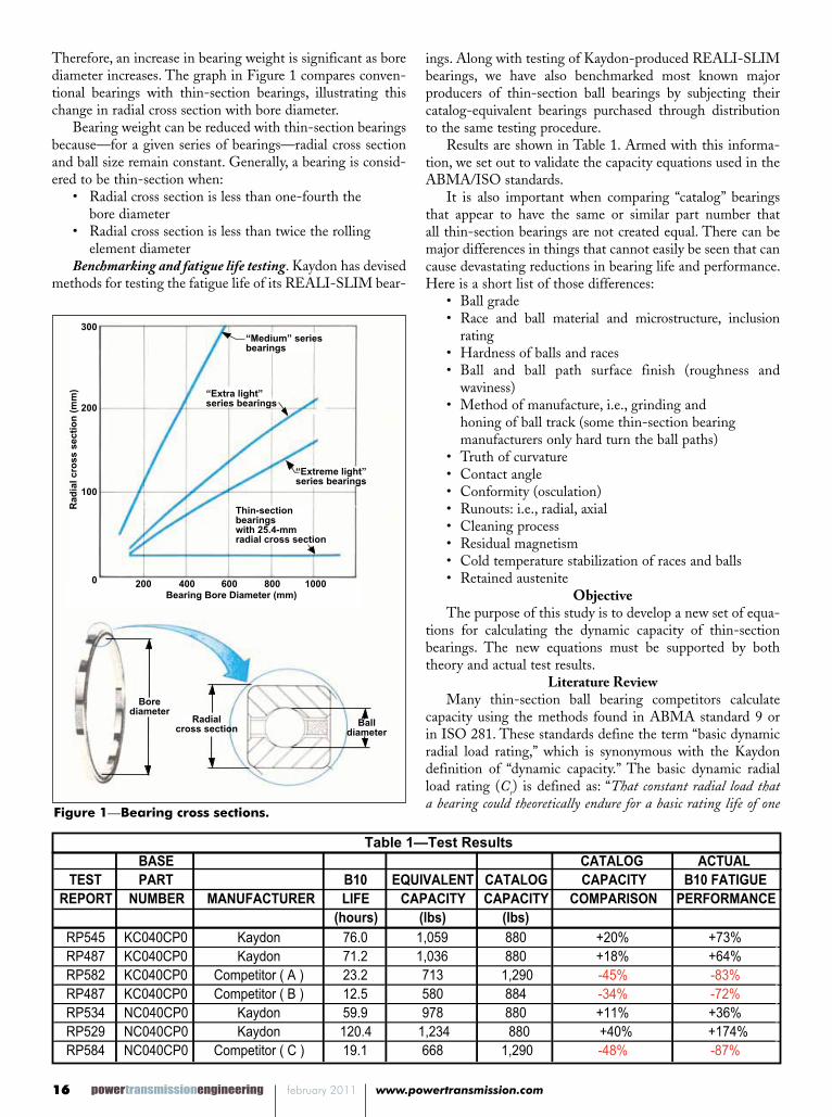
When is a bearing thin-section? Rolling element bearing dimensions have been standardized by the ABMA so that for a given bore diameter, bearings are manufactured with different outside diameters. For a given outside diameter, bearings are made in different widths. Each bearing belongs to a dimension series that can be designated by diameter and width.
For a conventional series of ball bearings, radial cross sec-tion and ball diameter typically increase with bore diameter.
powertransmissionengineering february 2011 www.powertransmission.com16 powertransmissionengineering february 2011 www.powertransmission.com
ings. Along with testing of Kaydon-produced REALI-SLIM bearings, we have also benchmarked most known major producers of thin-section ball bearings by subjecting their catalog-equivalent bearings purchased through distribution to the same testing procedure.
Results are shown in Table 1. Armed with this informa-tion, we set out to validate the capacity equations used in the ABMA/ISO standards.
It is also important when comparing “catalog” bearings that appear to have the same or similar part number that all thin-section bearings are not created equal. There can be major differences in things that cannot easily be seen that can cause devastating reductions in bearing life and performance. Here is a short list of those differences:
• Ball grade• Race and ball material and microstructure, inclusion
rating• Hardness of balls and races• Ball and ball path surface finish (roughness and
waviness)• Method of manufacture, i.e., grinding and honing of ball track (some thin-section bearing manufacturers only hard turn the ball paths)• Truth of curvature• Contact angle • Conformity (osculation)• Runouts: i.e., radial, axial • Cleaning process • Residual magnetism• Cold temperature stabilization of races and balls• Retained austenite
ObjectiveThe purpose of this study is to develop a new set of equa-
tions for calculating the dynamic capacity of thin-section bearings. The new equations must be supported by both theory and actual test results.
Literature ReviewMany thin-section ball bearing competitors calculate
capacity using the methods found in ABMA standard 9 or in ISO 281. These standards define the term “basic dynamic radial load rating,” which is synonymous with the Kaydon definition of “dynamic capacity.” The basic dynamic radial load rating (Cr) is defined as: “That constant radial load that a bearing could theoretically endure for a basic rating life of one
Therefore, an increase in bearing weight is significant as bore diameter increases. The graph in Figure 1 compares conven-tional bearings with thin-section bearings, illustrating this change in radial cross section with bore diameter.
Bearing weight can be reduced with thin-section bearings because—for a given series of bearings—radial cross section and ball size remain constant. Generally, a bearing is consid-ered to be thin-section when:
• Radial cross section is less than one-fourth the bore diameter• Radial cross section is less than twice the rolling element diameterBenchmarking and fatigue life testing. Kaydon has devised
methods for testing the fatigue life of its REALI-SLIM bear-
powertransmissionengineering february 2011 www.powertransmission.com powertransmissionengineering february 2011 www.powertransmission.com www.powertransmission.com february 2011 powertransmissionengineering 17
bm = Material factor for contemporary steels (bm = 1.3)fc = Geometry factor from tablesi = Number of rowsa = Contact angleZ = Number of balls per rowDb = Ball diameterPr = Applied radial load
Both standards provide tables for the geometry factor (fc). The material factor (bm) was added to ISO 281 in 1990. It equals 1.3 for radial and angular contact ball bearings made of contemporary steels. The 1990 version of ABMA standard 9 does not include this factor. However, the tables for factor fc are 1.3 times higher than the ISO 281 tables. Therefore, the two standards give exactly the same capacity.
The factor fc can also be calculated using the equation below:
(See above for Equation 3)
where: The units in this equation are kg and mm. For radial and
angular contact ball bearings l= 0.95. For 4-point contact bearings l= 0.90. If we let fi and fo equal the inner and outer curvature ratio (rx/Db) and convert the units to N and mm, this equation can be rewritten as:
(See above for Equation 4)
million revolutions.”These standards also define the L10 bearing fatigue life as:
“The basic rating life in millions of revolutions for 90% reliability.”The L10 life is then calculated from the load rating (Cr)
using Equation 1. Please note that the basic dynamic radial load rating, as defined in these two standards, is not the maxi-mum operating load for the bearing; it is simply a constant used in the life equation. It is often greater than the “static” radial load rating (Cor). Loading the bearing beyond the static rating will cause permanent deformation, or “brinelling.” Both standards state:
“The life formula gives satisfactory results for a broad range of bearing loads. (However), the user should consult the bearing manufacturer to establish the applicability of the life formula in cases where (the applied load) Pr exceeds (the static capacity) Co or (one-half the dynamic rating) 0.5 Cr whichever is smaller.”
(See above for Equation 1)
These two standards give the following equations for cal-culating the basic dynamic load rating (Cr):
(See above for Equation 2)
where:L10 = The basic life rating in millions revolutions for 90% reliabilityCr = Basic dynamic radial load rating
Eg. 1
3
10 =
r
r
P
CL million revolutions ...................... ISO 281 par 5.3.1
These two standards give the following equations for calculating the “Basic DynamicLoad Rating” (C r):
8.13/27.0)cos( bcmr DZifbC = for ball size (Db) 1 inch.
1.5 rap 182OSI2 .gE8.13/27.0)cos(647.3 bcmr DZifbC = for ball size (Db) > 1 inch
≤
106
Eg. 3
41.0
3/1
39.13.03.03/1041.072.1
2
2
)1(
)1(
2
2
1
104.111.4
bi
i
bi
bo
o
ic Dr
r
Dr
Dr
r
rf
where: p
bD
CosD Palmgren Table 3.2
Eg. 4
41.0
3/1
39.13.03.03/1041.072.1
12
2
)1(
)1(
12
12
1
104.1120.38
i
i
i
o
o
ic f
f
f
f
f
ff
Ref. Harris eq. 18.106
Eg. 3
41.0
3/1
39.13.03.03/1041.072.1
2
2
)1(
)1(
2
2
1
104.111.4
bi
i
bi
bo
o
ic Dr
r
Dr
Dr
r
rf
where: p
bD
CosD Palmgren Table 3.2
Eg. 4
41.0
3/1
39.13.03.03/1041.072.1
12
2
)1(
)1(
12
12
1
104.1120.38
i
i
i
o
o
ic f
f
f
f
f
ff
Ref. Harris eq. 18.106
Equation 1
Equation 2
Equation 3
Equation 4
continued
powertransmissionengineering february 2011 www.powertransmission.com18 powertransmissionengineering february 2011 www.powertransmission.com
The fc values used in the ABMA Standard 9 and ISO 281 tables are based on a number of assumptions. These include the following:
• Inner-ring raceway cross sectional radius ≤ 0.52 Db (curvature ratio ≤ 52%)• Outer-ring raceway cross sectional radius ≤ 0.53 Db
(The fc tables in these standards were actually calculated using 52%)• 52100 steel per ASTM A-295• Adequate lubrication • Free of contamination • Film thickness > the composite surface roughness• Inner and outer races are rigidly supported and properly aligned• Nominal internal clearance after mounting (“nominal” in this context means zero or no preload)• Radial ball bearings are made to ABEC 1 or better tolerances per ANSI/ABMA standard 20 (thin-section bearings are made per ANSI/ABMA
standard 26.2)• No truncation of the contact ellipseKaydon does not use these equations to calculate dynamic
capacity because most of these assumptions are not valid for thin-section bearings, and were never intended to be. Most importantly, the life calculated using these equations is not supported by Kaydon testing. Nevertheless, many Kaydon competitors use these equations anyway (Table 2).
According to the old Kaydon capacity equations, the dynamic capacity of a KC040CP0 is 880 lbs. Under a radial load of 525 lbs., the predicted L10 life at 1780 RPM is 44.7 hrs. If the capacity is calculated using the 1978 ABMA/ISO equations, with fc calculated using Equation 4, (rather than the using the tables), the capacity should be 1,274 lbs. This gives a life of 133.8 hours. The actual average L10 life for these bearings over the last five years has been 80.2 hours. The actual life is almost double the life predicted by the old Kaydon equations, but apparently less than predicted by the ABMA/ISO equations.
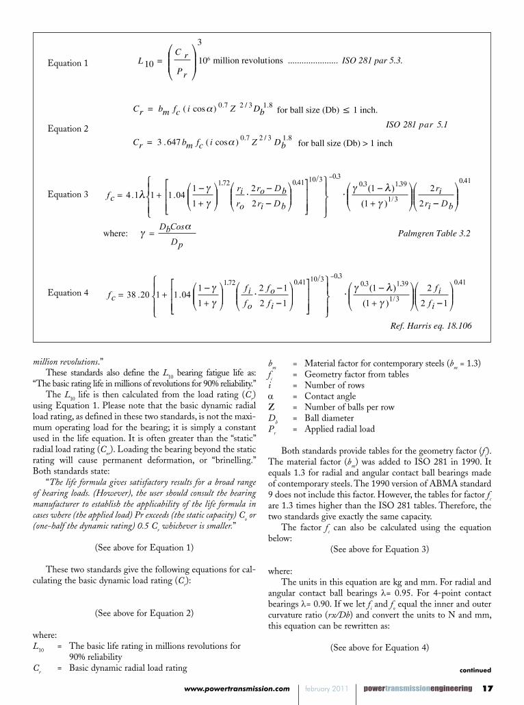
However, we know that life under a radial load decreases as the clearance increases. This is because fewer balls carry the radial load (Fig. 2). The theoretical L10 life was calculated for the KC040CP0 bearing under a 525 lb. load at 1,780 rpm and was plotted for various amounts of diametrical clearance. The life calculations use the ABMA/ISO capacity (adjusted for curvature), in the life prediction. As shown in Figure 3, the actual measured L10 life falls very close to the predicted
powertransmissionengineering february 2011 www.powertransmission.com powertransmissionengineering february 2011 www.powertransmission.com www.powertransmission.com february 2011 powertransmissionengineering 19
continued
values when clearance is considered.In summary, Kaydon life testing does support the use
of the ABMA/ISO (1978) capacity values, when curvature and clearance are considered. However, it does not support the modern materials factor (bm) that was added in 1990. Therefore, it is important that the assumptions behind these equations are understood.
The purpose of a published capacity is to allow the cus-tomer to use a quick (Cr/Pr)
3 equation to estimate life (Eq. 1). The ABMA/ISO equations are not adequate for this purpose because they don’t consider the curvature or clearance in the basic dynamic load rating. Therefore, alternate methods must be used to calculate the published ratings for these bearings.
Test MethodPreparation: The test parameters (i.e., load and speed)
must first be calculated. These are selected to cause the bearings to fail by fatigue in a reasonable time period (typi-cally less than 100 hours), while not subjecting the bearing to excessive loads. Therefore the testing speed is set to 1,780 rpm.
The desired radial test load is calculated from the life equation (Eq. 1). To get the life in hours, simply divide the life in revolutions by the rotating speed as shown in Equation 5.
(See above for Equation 5)
Where:Lh is the L10 life in hours under the test conditions
Cr is the dynamic load rating for the bearing (from a catalog or calculation)
Pr is the applied radial load
N is the speed of the bearing under test, in RPMs.
We can then rearrange Equation 5 and solve for the applied radial load Pr. For an L10 life of approximately 50 hours, the radial load should be a little less than 60% of the rated capacity (Eq. 6). Keep in mind that the L10 life is based on 90% reliability. This means that 90% of the test samples are expected to exceed the 50 hours. For the Kaydon KC040CP0 bearing, a radial load of 525 lbs. was selected.
(6)
Bearings to be tested are randomly selected from the identified lot. At minimum of 20 pieces are used for each test. Each bearing is identified with a unique reference number.
Bearings are cleaned as assemblies prior to test by mechani-cal agitation in mineral spirits for at least five minutes.
Each bearing is then mounted in a suitable housing, mak-
KC040XP0Calculated Life vs Diametral Clearance Under 525 lb Radial Load
Figure 2 – Life vs. Diametral ClearanceFigure 3—Life vs. diametral clearance.
FIGURE 1
Figure 4—Test arrangement.
Equation 5
ing witness marks to indicate orientation in housings, and then mounted on a driven spindle with the axis horizontal as shown in Figure 4.
A steel load strap is then attached to the outer race and connected to an air cylinder arranged to apply radial load to the bearing. The centerline of the air cylinder, the steel strap and the lower tooling are aligned in the same plane as the bearing centerline.
The force exerted by the load cylinder is measured by a portable load cell and digital indicator. The air pressure to the load cylinder is adjusted to produce the desired radial load on the bearing. Note: In calculating the total radial load on the bearing, the weight of the tooling is also considered.
An accelerometer is mounted on top of the stationary housing with radial orientation, and is connected to the auto-matic monitoring equipment.
The circulating oil system is checked for adequate oil level and to ensure that filter replacement is not overdue.
Starting test. The circulating oil to lubricate the test bear-
Eg. 5
Eg. 6
)(667,16
60
110
3
minmin
63
hrsNP
C
NP
CL
r
rrev
hrr
rh
×
3/1667,16
⋅
hr
r
LNC
P
Eg. 5
Eg. 6
)(667,16
60
110
3
minmin
63
hrsNP
C
NP
CL
r
rrev
hrr
rh
×
3/1667,16
⋅
hr
r
LNC
P
powertransmissionengineering february 2011 www.powertransmission.com20 powertransmissionengineering february 2011 www.powertransmission.com
bearing has averaged 189.3 hours. If we plug these numbers into Equation 5 and solve for the capacity (Cr), we get a radial capacity of 1,073 lbs. for the radial bearing and 1,430 lbs. for the four-point contact bearing. (Eq. 7)
(7)
These values are much greater than the old Kaydon rat-ings of 880 lbs. for both. However, they still fall short of the ABMA/ISO ratings for radial bearings calculated using the fc values from the tables. (Neither ABMA or ISO publish ratings for four-point contact ball bearings.) The main reason for the apparent discrepancy is the poor assumptions these standards make regarding race curvature and diametrical clearance. Based on the results of these tests, it is apparent that a new method is required for calculated the dynamic radial capacity for thin-section bearings.
New Kaydon EquationsThe new Kaydon capacity calculations are based on the
contact stress and the number of stress cycles at the highest loaded point of the stationary ring. The highest loaded point is always the same spot on the stationary ring. It is variable on the rotating ring. Both the ABMA and ISO calculations assume that the inner race is rotating and the outer race is stationary. Therefore, the new equations are based on the outer ring stress. The inner ring may have a higher contact stress, but the load is distributed over the entire circumfer-ence, so there are fewer stress cycles under the max load. The new dynamic capacity is derived from the basic life equation, as shown below.
(See pg 21 for Equation 8)
where:Cr The basic dynamic load rating (dynamic capacity)Pr The radial load for a life of 108 stress cyclesL10 The number of revolutions for 108 stress cyclesf The number of stress cycles per revolutionQmax The normal ball load on the highest loaded ball for
108 stress cyclesZ The number of balls per rowi The number of rows of contacta The contact angleS The ball load distribution factor based on the diametrical clearancel The stress factor: l=1 for angular (A) and radial (C)
contact bearings and l= (.9/.95) for four-point (X) contact bearings
Maximum ball load (Qmax). The factor Qmax is the normal ball load that gives a mean contact stress of 262,500 psi in the outer race. This is the stress value associated with 108 stress cycles. This stress value was determined experimentally dur-ing Kaydon laboratory testing. The L10 life in revolutions is then calculated by dividing the number of stress cycles (108) by the number of stress-cycles-per-revolution (f) which is calculated using Equation 9.
Stress cycles per revolution:
ing is connected and turned on. The cooling water to the oil heat exchangers is turned on. Air to the load cylinder is set to off.
The drive motor is “jogged” to ensure that no components are loose and that there is no unwanted interference between the rotating and stationary parts. The motor is then turned on and the reading (in hours and tenths) of the elapsed time meter is noted. All test notes are recorded on the test data collection sheet.
Oil flow to the bearing is adjusted to be as high as possible without causing excessive foaming or leakage from the bear-ing housing. Oil flowing to each bearing should not exceed a temperature of 130° F. Air to the load cylinder is then turned on.
The baseline radial vibration is measured. The auto shut-off system is then set for this baseline vibration level. The automatic shut-down occurs when vibration increases to 150% of the baseline level.
Stopping test. When bearing failure is suspected, either due to audible noise or to auto shut-off, the bearing rotation is stopped. The bearing is then disassembled and inspected.
If no visible signs of spalling or other failure are found on the balls/rollers or race paths, the bearing is reassembled and remounted in the test housings, noting the orientation of wit-ness marks. The testing is then resumed (with the automatic shut-down system, baseline vibration level reset if necessary).
If spalling is found, the hour meter reading is noted and the elapsed time is calculated. Also, the location and degree of spalling is noted, and then the bearing components are bagged, identified and saved.
After all bearings in the test have been run to failure, the elapsed times are entered into the Kaydon-Weibull analysis software program. This program establishes the best-fit Weibull line for the data, calculates the slope and scale parameters and determines the L10 fatigue life for the sample group.
The L10 value obtained from the Weibull program is then compared to the theoretical L10 fatigue life at the tested load and speed. If the observed L10 value does not meet or exceed the theoretical L10 value, an investigation is conducted to determine the root cause.
The Weibull slope parameter gives an indication of the degree of scatter in the test results. For through-hardened AISI 52100 bearing steel races, a Weibull slope value in the range 1.0–1.5 is expected, with a lower value indicating a greater degree of fatigue life dispersion and a higher value indicating less scatter.
At least one failed bearing race is then sectioned and mounted through the failed area (spall). At a minimum the following metallurgical properties are evaluated and recorded:
ResultsOver the last five years of testing, the Kaydon KC040CP0
radial bearing has had an average L10 life of 80.2 hours in Kaydon testing. The Kaydon KC040XP0, four-point contact
Eg. 7
Eg. 8
1073
16667
178080525
16667
3/13/110
⋅
NLPC r
λα 3
131
31
31 100100
10
/10
10
7.
6
8
610
fS
CosZiQ
fP
fP
LPC max
rrrr
powertransmissionengineering february 2011 www.powertransmission.com powertransmissionengineering february 2011 www.powertransmission.com www.powertransmission.com february 2011 powertransmissionengineering 21
continued
(9)
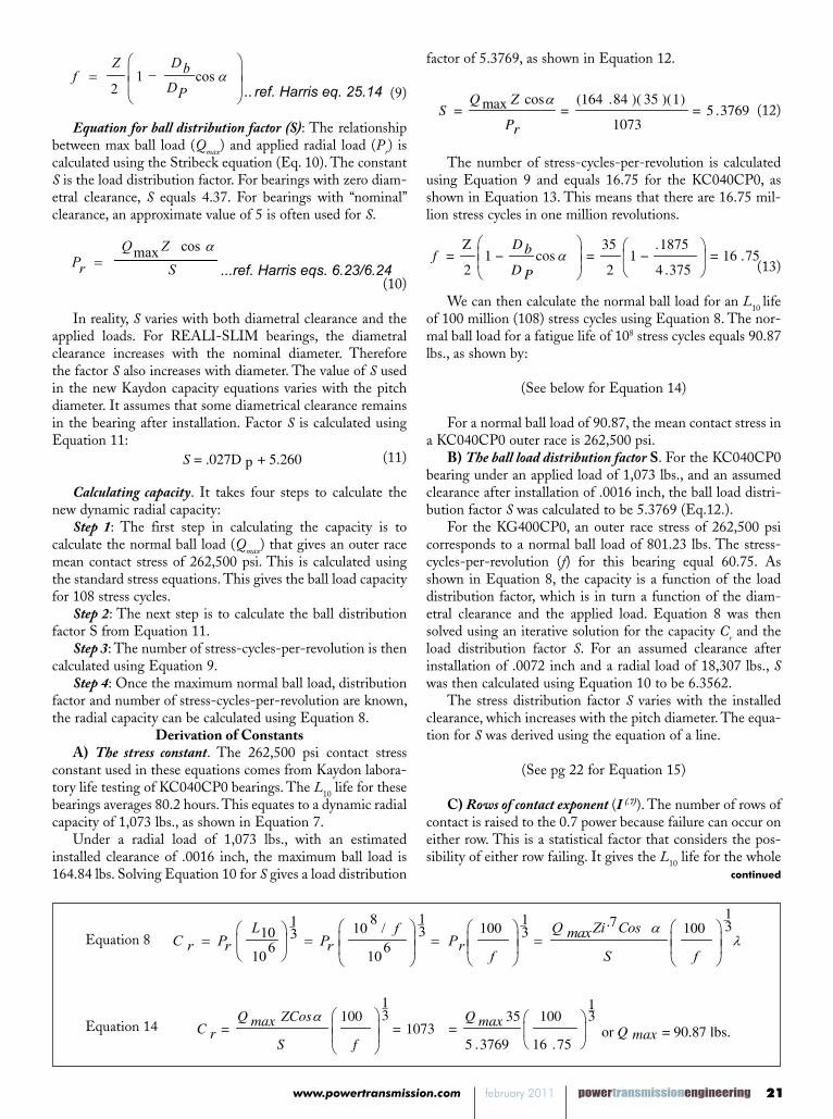
Equation for ball distribution factor (S): The relationship between max ball load (Qmax) and applied radial load (Pr) is calculated using the Stribeck equation (Eq. 10). The constant S is the load distribution factor. For bearings with zero diam-etral clearance, S equals 4.37. For bearings with “nominal” clearance, an approximate value of 5 is often used for S.
(10)
In reality, S varies with both diametral clearance and the applied loads. For REALI-SLIM bearings, the diametral clearance increases with the nominal diameter. Therefore the factor S also increases with diameter. The value of S used in the new Kaydon capacity equations varies with the pitch diameter. It assumes that some diametrical clearance remains in the bearing after installation. Factor S is calculated using Equation 11:
(11)
Calculating capacity. It takes four steps to calculate the new dynamic radial capacity:
Step 1: The first step in calculating the capacity is to calculate the normal ball load (Qmax) that gives an outer race mean contact stress of 262,500 psi. This is calculated using the standard stress equations. This gives the ball load capacity for 108 stress cycles.
Step 2: The next step is to calculate the ball distribution factor S from Equation 11.
Step 3: The number of stress-cycles-per-revolution is then calculated using Equation 9.
Step 4: Once the maximum normal ball load, distribution factor and number of stress-cycles-per-revolution are known, the radial capacity can be calculated using Equation 8.
Derivation of ConstantsA) The stress constant. The 262,500 psi contact stress
constant used in these equations comes from Kaydon labora-tory life testing of KC040CP0 bearings. The L10 life for these bearings averages 80.2 hours. This equates to a dynamic radial capacity of 1,073 lbs., as shown in Equation 7.
Under a radial load of 1,073 lbs., with an estimated installed clearance of .0016 inch, the maximum ball load is 164.84 lbs. Solving Equation 10 for S gives a load distribution
factor of 5.3769, as shown in Equation 12.
(12)
The number of stress-cycles-per-revolution is calculated using Equation 9 and equals 16.75 for the KC040CP0, as shown in Equation 13. This means that there are 16.75 mil-lion stress cycles in one million revolutions.
(13)
We can then calculate the normal ball load for an L10 life of 100 million (108) stress cycles using Equation 8. The nor-mal ball load for a fatigue life of 108 stress cycles equals 90.87 lbs., as shown by:
(See below for Equation 14)
For a normal ball load of 90.87, the mean contact stress in a KC040CP0 outer race is 262,500 psi.
B) The ball load distribution factor S. For the KC040CP0 bearing under an applied load of 1,073 lbs., and an assumed clearance after installation of .0016 inch, the ball load distri-bution factor S was calculated to be 5.3769 (Eq.12.).
For the KG400CP0, an outer race stress of 262,500 psi corresponds to a normal ball load of 801.23 lbs. The stress-cycles-per-revolution (f) for this bearing equal 60.75. As shown in Equation 8, the capacity is a function of the load distribution factor, which is in turn a function of the diam-etral clearance and the applied load. Equation 8 was then solved using an iterative solution for the capacity Cr and the load distribution factor S. For an assumed clearance after installation of .0072 inch and a radial load of 18,307 lbs., S was then calculated using Equation 10 to be 6.3562.
The stress distribution factor S varies with the installed clearance, which increases with the pitch diameter. The equa-tion for S was derived using the equation of a line.
(See pg 22 for Equation 15)
C) Rows of contact exponent (I (.7)). The number of rows of contact is raised to the 0.7 power because failure can occur on either row. This is a statistical factor that considers the pos-sibility of either row failing. It gives the L10 life for the whole
powertransmissionengineering february 2011 www.powertransmission.com22
already factored into the maximum allowable stress level, which was established by testing.)
E) Four-point contact bearing. Using the new capacity cal-culation (Eq. 8), the radial capacity of a KC040XP0 (4-point) bearing is 1,417 lbs. If we plug this number into the life equa-tion (Eq. 5), the L10 life under a test load of 525 lbs. at 1,780 rpm is 184 hours (Eq. 16). In Kaydon testing, the L10 life of a standard KC040XP0 was actually 189.3 hours. Therefore, there is excellent correlation between the theoretical and measured capacity.
(See above for Equation 16)
ConclusionsThe new Kaydon capacity equations are based on the
maximum contact stress and the number of stress cycles per revolution. They consider the actual curvature of the races. They also consider the diametral clearance. The new capaci-ties are supported by actual test data. The new radial capacity for radial (C-type) bearings ranges from 36% higher in the KAA10CL0 to no change in the KG400CP0. The radial capacity of four-point contact (X-type) bearings increases from 31% to 77% depending on the bearing size. The new capacities are still lower than the ABMA/ISO numbers, which are based on very poor assumptions. The new Kaydon equations provide a more accurate estimate of actual bearing life when used in the basic L10 = (Cr/Pr)
3 equation. These equations apply to Kaydon Catalog 300 bearings
with standard clearance only. Preload and clearance have a significant influence on bearing life. Clearance after installa-tion will vary depending on fits and shaft/housing materials. The Catalog 300 capacity should be used for an initial bear-ing selection only. Life can then be confirmed using more advanced Kaydon programs. These programs use the ISO/ABMA capacity, but also take the curvature and clearance/preload into consideration.
References:1. Load Ratings and Fatigue Life for Ball Bearings, ANSI/AFBMA Std. 9, (1978).2. Load Ratings and Fatigue Life for Ball Bearings, ANSI/AFBMA Std. 9, (1990).3.Rolling Bearings–Dynamic Load Ratings and Rating Life, ISO 281, (1990).4. T. Harris, Rolling Bearing Analysis, 3rd Ed., J Wiley & Sons USA (1991).5. Palmgren, A. “Ball and Roller Bearing Engineering”, 3rd Ed., SKF Industries, Inc., Philadelphia, PA. (1959).
bearing and is lower than the life for the individual rows. This factor is consistent with both the ISO/ABMA calculations as well as the old Kaydon method.
D) The stress factor (l). The tables in both ABMA Standard 9 and ISO 281 show multiple columns for factor fc. The first column is titled “Single Row Radial Contact” and “Single and Double Row Angular Contact.” The second column is titled “Double Row Radial Contact” and has a lower value for fc. The reason for this is described on page 81 and table 3.3 of “Ball and Roller Bearing Engineering” by A. Palmgren (1959). Palmgren shows a l of .95 for single-row radial bearings, and for single- and double-row angular contact bearings. He also shows a l=.90 for double-row radial bearings. It is described as a “stress factor.” This factor allows for uneven load sharing between the two rows of contact. Therefore, Kaydon has chosen a de-rating factor of (l=.90/.95) for four-point contact (X-type) ball bearings. (The 0.95 factor for radial and angular contact bearings is
Robert Roos has been a senior prod-uct engineer with Kaydon Corporation Bearings Division for 10 years. He earned a bachelor’s degree in mechani-cal engineering from the University of Michigan and a master’s degree in mechanichal engineering from Western Michigan University. Roos is a li-censed professional engineer in the state of Michigan. He holds two patents and is a member of the ASTM F34 com-mittee for rolling element bearings.
Scott A. Hansen is vice president of manufacturing planning for Kaydon Corporation Bearings Division. His 30 years with Kaydon include posi-tions in product design, manufactur-ing and operations. He holds a bach-elor’s degree from Western Michigan University and two patents—for a wind turbine pitch bearing and a robot pivot arm assembly for semiconductor wafer handling. Hansen belongs to the ASTM F34 rolling element bearings group and the ABMA engineering specification group.