+ All Categories
Home > Documents > NOTE: For Dually w 8’ Bed applications see kit 756 -0 A ... · Driver-Side Orientation...

NOTE: For Dually w 8’ Bed applications see kit 756 -0 A ... · Driver-Side Orientation...

Date post: 07-Jul-2020
Category:
Upload: others
View: 3 times
Download: 0 times
Share this document with a friend
7
www.amp-research.com /5 IM75406 rev 05.27.5 BedStep2™ is invented, designed, engineeried and manufactured exclusively by AMP Research and may be covered by one of the following patents: 6,641,158; 6,830,257; 6,938,909; 7,055,839; 7,380,807; 7,398,985; 7,584,975. Made in USA © 2011 AMP Research Three-year limited warranty. Professional installation is recommended. AMP RESEARCH TECH SUPPORT 1-888-983-2204 (Press 2) Monday - Friday, 6:00 AM - 5:00 PM PST Dodge Ram DS 1500 (2009-2015) 2500 (2010-2013) 3500 (2010-2013) Excludes 2013 dually w 8’ Bed 1 9 8 4 6 10 11 12 3 2 7 Torque wrench 13 mm PART NUMBER: 75406-01A 15 mm T25 1/4” Drill Bit 3/8” Drill Bit 5 1 For 6.5’ & 8’ bed lengths components must be configured for Passenger or Drivers-Side as shown. Passenger-Side Orientation Driver-Side Orientation NOTE: For Dually w 8’ Bed applications see kit 756-0A for proper bracket orientation. For 5.5’ bed length components must be configured for Passenger or Drivers-Side as shown. Driver-Side Orientation Passenger-Side Orientation
Transcript

www.amp-research.com �/5 IM75406 rev 05.27.�5

BedStep2™ is invented, designed, engineeried and manufactured exclusively by AMP Research and may be covered by one of the following patents: 6,641,158; 6,830,257; 6,938,909; 7,055,839; 7,380,807; 7,398,985; 7,584,975. Made in USA © 2011 AMP Research Three-year limited warranty. Professional installation is recommended.

AMP RESEARCH TECH SUPPORT 1-888-983-2204 (Press 2) Monday - Friday, 6:00 AM - 5:00 PM PST

Dodge Ram DS 1500 (2009-2015)2500 (2010-2013) 3500 (2010-2013) Excludes 2013 dually w 8’ Bed

1

9

8

4

610

11

123

2

7

Torque wrench

13 mm

PART NUMBER:75406-01A

15 mm

T25 1/4” Drill Bit

3/8” Drill Bit

5

1

For 6.5’ & 8’ bed lengths components must be configured for Passenger or Drivers-Side as shown.

Passenger-Side OrientationDriver-Side Orientation

NOTE: For Dually w 8’ Bed applications see kit 756��-0�A for proper bracket orientation.

For 5.5’ bed length components must be configured for Passenger or Drivers-Side as shown.

Driver-Side Orientation Passenger-Side Orientation

www.amp-research.com 2/5 IM75406 rev 05.27.�5

13mm

13mm

4

4

5 6

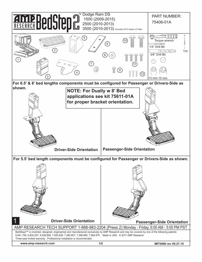
Hole set A is to be used on 6.5’ and 8’ bedsHole set B is to be used on 5.5’ beds.

2 3

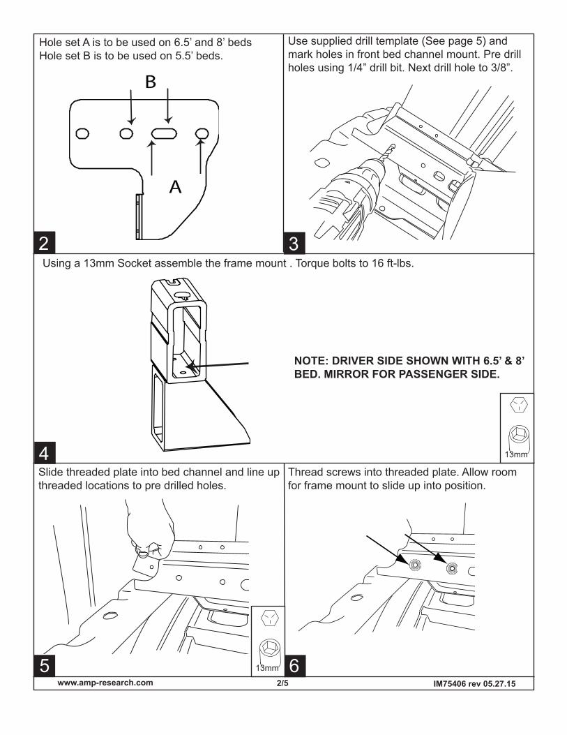
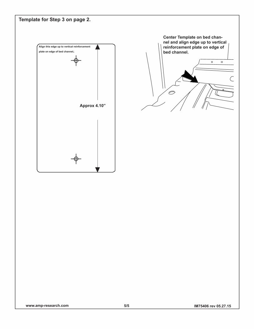
Use supplied drill template (See page 5) and mark holes in front bed channel mount. Pre drill holes using 1/4” drill bit. Next drill hole to 3/8”.

A

B

Using a 13mm Socket assemble the frame mount . Torque bolts to 16 ft-lbs.

NOTE: DRIVER SIDE SHOWN WITH 6.5’ & 8’ BED. MIRROR FOR PASSENGER SIDE.

Slide threaded plate into bed channel and line up threaded locations to pre drilled holes.

Thread screws into threaded plate. Allow room for frame mount to slide up into position.

www.amp-research.com �/5 IM75406 rev 05.27.�5

5

9

8

10

11 12

13mm

7

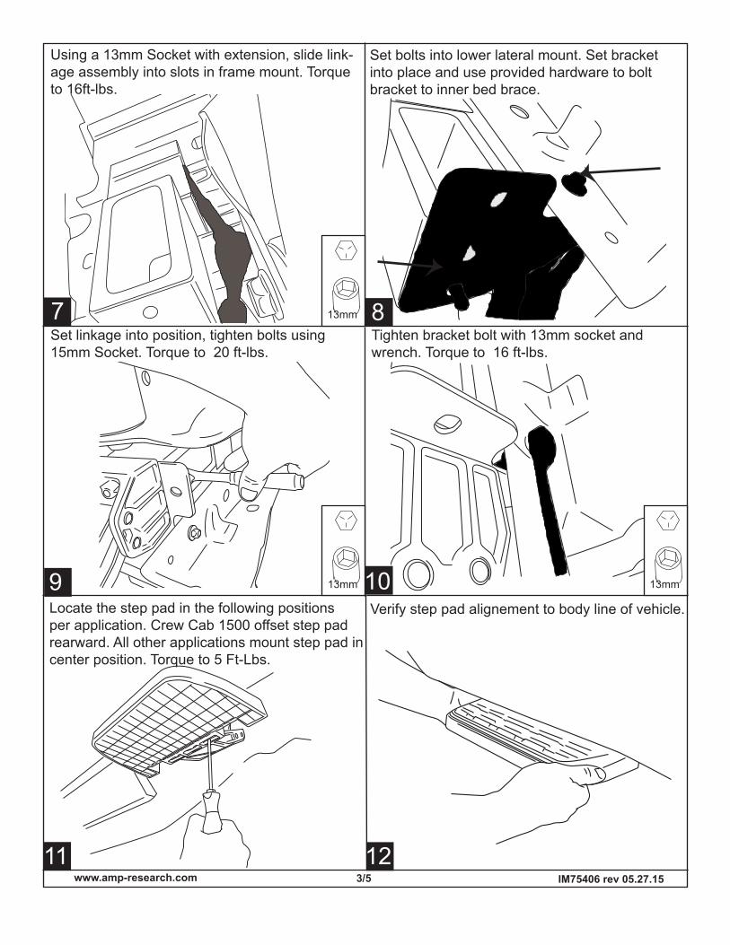
Using a 13mm Socket with extension, slide link-age assembly into slots in frame mount. Torque to 16ft-lbs.

Set bolts into lower lateral mount. Set bracket into place and use provided hardware to bolt bracket to inner bed brace.

Set linkage into position, tighten bolts using 15mm Socket. Torque to 20 ft-lbs.

Tighten bracket bolt with 13mm socket and wrench. Torque to 16 ft-lbs.

13mm

13mm

Locate the step pad in the following positions per application. Crew Cab 1500 offset step pad rearward. All other applications mount step pad in center position. Torque to 5 Ft-Lbs.

Verify step pad alignement to body line of vehicle.

www.amp-research.com 4/5 IM75406 rev 05.27.�5

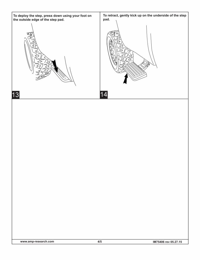
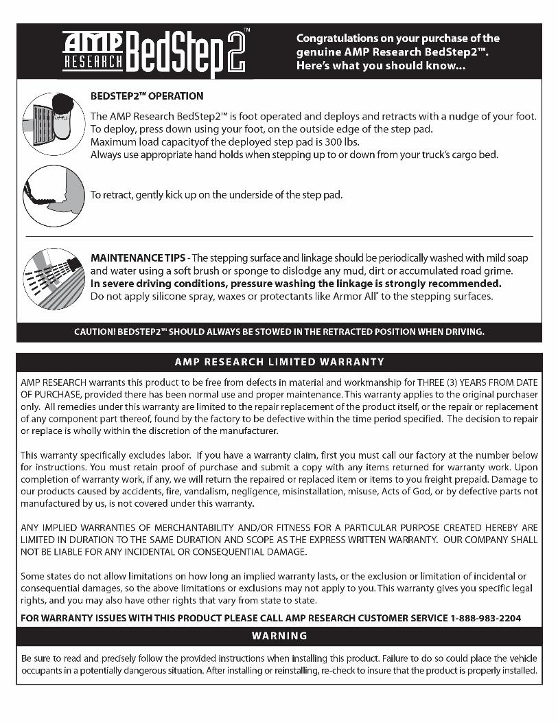
To deploy the step, press down using your foot on the outside edge of the step pad.

To retract, gently kick up on the underside of the step pad.

13 14

www.amp-research.com 5/5 IM75406 rev 05.27.�5

Center Template on bed chan-nel and align edge up to vertical reinforcement plate on edge of bed channel.

Approx 4.�0”

Align this edge up to vertical reinforcement

plate on edge of bed channel.

Template for Step � on page 2.


Recommended