MARINE GUIDANCE NOTE MGN 301 (M + F) Manoeuvring Information on Board Ships Note to Shipbuilders, shipowners, ship Managers and Masters This note supersedes Marine Guidance Note MGN 201 (M+F) Summary • The MCA recommends that manoeuvring information in the form of a pilot card, wheelhouse poster and manoeuvring booklet should be provided on board ships. • The Appendices to this Note contain examples of such manoeuvring information. Introduction 1. At its 15th session, the Assembly of the International Maritime Organisation adopted a recommendation for the provision and the display of manoeuvring data on board ships as set out in the annex to Resolution A.601 (15). Application 2. The Maritime and Coastguard Agency recommends that manoeuvring information in the form of a pilot card, wheelhouse poster and manoeuvring booklet should be provided as follows: • .1 the pilot card on all ships to which the requirements of the 1974 SOLAS Convention, as amended, apply; • .2 the pilot card, wheelhouse poster and manoeuvring booklet on all new ships and fishing vessels of 100 metres in length and over, and all new chemical tankers and gas carriers regardless of size; and • .3 the pilot card, wheelhouse poster and manoeuvring booklet on all new ships that may pose a hazard due to unusual dimensions or characteristics. 3. The manoeuvring information should be amended after any modification or conversion of the ship which may alter its manoeuvring characteristics or extreme dimensions. Manoeuvring Information Pilot Card (Appendix 1) 4. The pilot card, to be filled in by the master, is intended to provide information to the pilot on boarding the ship. This information should describe the current condition of the ship, with regard to its loading, propulsion and manoeuvring equipment, and other relevant equipment. - 1 -
Transcript
MARINE GUIDANCE NOTE
MGN 301 (M + F)
Manoeuvring Information on Board Ships Note to Shipbuilders, shipowners, ship Managers and Masters
This note supersedes Marine Guidance Note MGN 201 (M+F)
Summary
• The MCA recommends that manoeuvring information in the form of a pilot card, wheelhouse poster and manoeuvring booklet should be provided on board ships.
• The Appendices to this Note contain examples of such manoeuvring information.
Introduction
1. At its 15th session, the Assembly of the International Maritime Organisation adopted a recommendation for the provision and the display of manoeuvring data on board ships as set out in the annex to Resolution A.601 (15).
Application
2. The Maritime and Coastguard Agency recommends that manoeuvring information in the form of a pilot card, wheelhouse poster and manoeuvring booklet should be provided as follows:
• .1 the pilot card on all ships to which the requirements of the 1974 SOLAS Convention, as amended, apply;
• .2 the pilot card, wheelhouse poster and manoeuvring booklet on all new ships and fishing vessels of 100 metres in length and over, and all new chemical tankers and gas carriers regardless of size; and
• .3 the pilot card, wheelhouse poster and manoeuvring booklet on all new ships that may pose a hazard due to unusual dimensions or characteristics.
3. The manoeuvring information should be amended after any modification or conversion of the ship which may alter its manoeuvring characteristics or extreme dimensions.
Manoeuvring Information
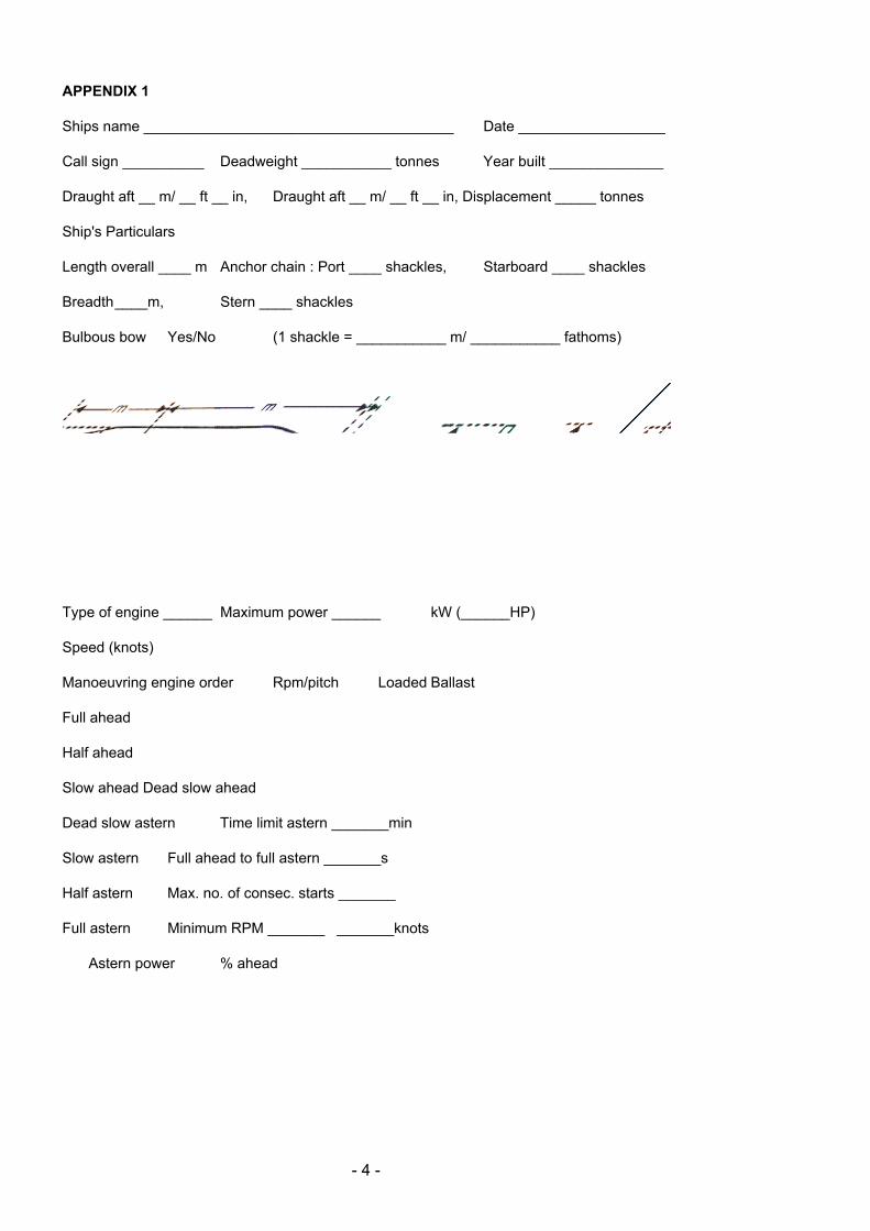
Pilot Card (Appendix 1)
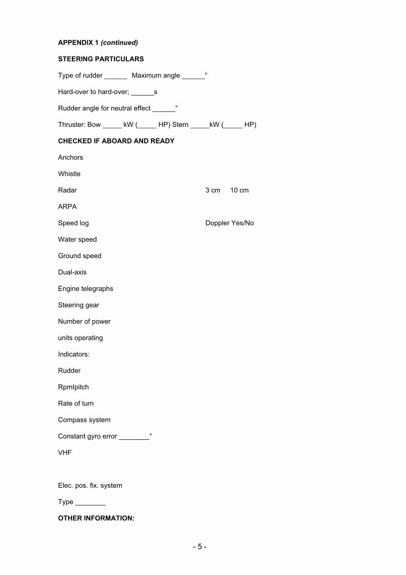
4. The pilot card, to be filled in by the master, is intended to provide information to the pilot on boarding the ship. This information should describe the current condition of the ship, with regard to its loading, propulsion and manoeuvring equipment, and other relevant equipment.
- 1 -
Note: The information provided in the pilot card should be available without the need to conduct special manoeuvring trials. Wheelhouse Poster (Appendix 2)
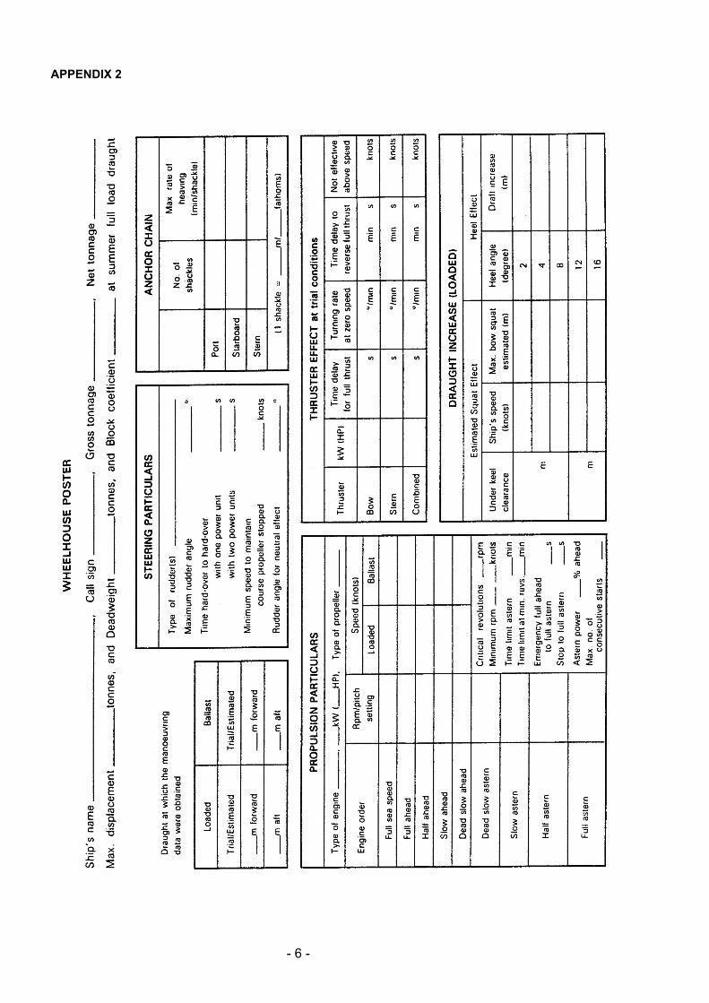
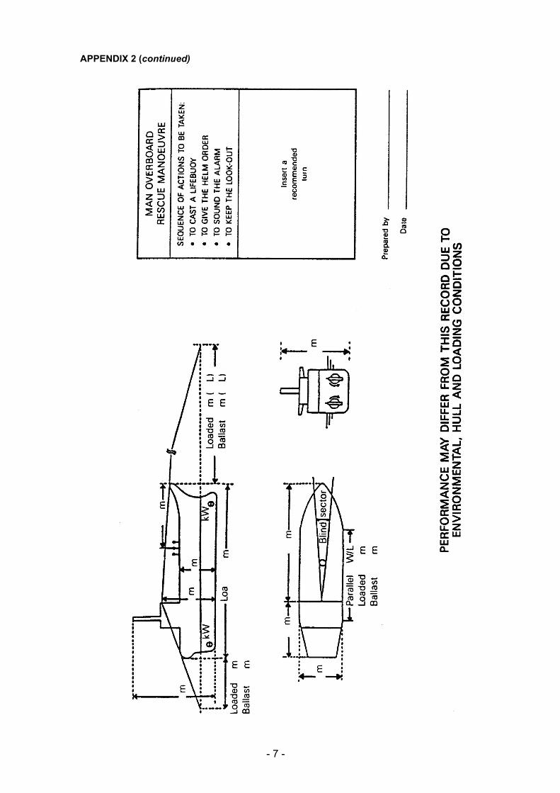
5. The wheelhouse poster should be permanently displayed in the wheelhouse. It should contain general particulars and detailed information describing the manoeuvring characteristics of the ship, and be of such a size to ensure ease of use.
Note: The manoeuvring characteristics may be determined by conducting special manoeuvring trials or by computer simulation techniques or by estimation. The master should bear in mind that the manoeuvring performance of the ship may differ from that shown on the poster due to environmental, hull and loading conditions.
Manoeuvring Booklet (Appendix 3)
6. The manoeuvring booklet should be available on board and should contain comprehensive details of the ship’s manoeuvring characteristics and other relevant data. The manoeuvring booklet should include the information shown on the wheelhouse poster together with other available manoeuvring information.
Note: Most of the manoeuvring information in the booklet can be estimated but some should be obtained from trials.
- 2 -
Further Information
Further information on the contents of this Notice can be obtained from:
Navigation Safety Branch Bay 2/29 Maritime and Coastguard Agency Spring Place 105 Commercial Road Southampton SO15 1EG
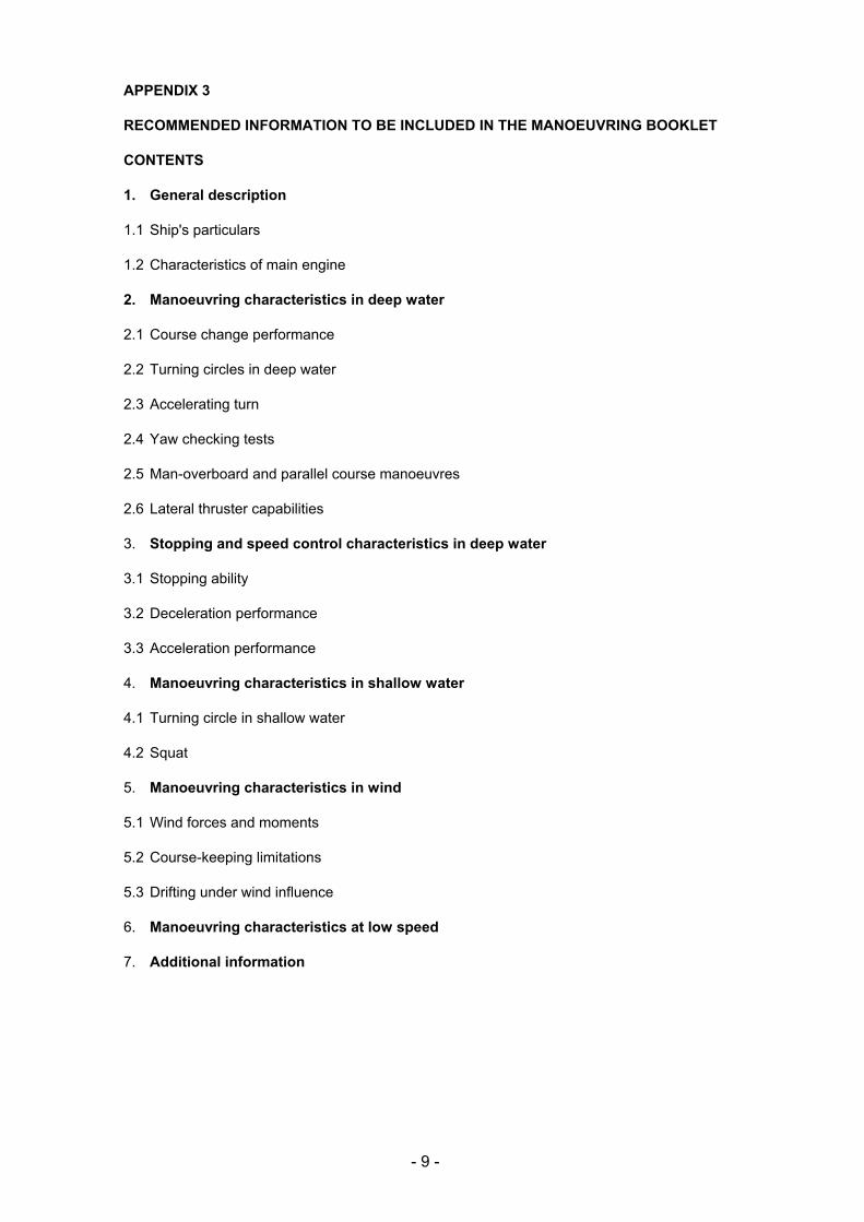
RECOMMENDED INFORMATION TO BE INCLUDED IN THE MANOEUVRING BOOKLET
CONTENTS
1. General description
1.1 Ship's particulars
1.2 Characteristics of main engine
2. Manoeuvring characteristics in deep water
2.1 Course change performance
2.2 Turning circles in deep water
2.3 Accelerating turn
2.4 Yaw checking tests
2.5 Man-overboard and parallel course manoeuvres
2.6 Lateral thruster capabilities
3. Stopping and speed control characteristics in deep water
3.1 Stopping ability
3.2 Deceleration performance
3.3 Acceleration performance
4. Manoeuvring characteristics in shallow water
4.1 Turning circle in shallow water
4.2 Squat
5. Manoeuvring characteristics in wind
5.1 Wind forces and moments
5.2 Course-keeping limitations
5.3 Drifting under wind influence
6. Manoeuvring characteristics at low speed
7. Additional information
- 9 -
1 GENERAL DESCRIPTION
1.1 Ship's particulars
1.1.1 General Ship's name, distinctive number or letters, year of build
1.1.2 Gross tonnage and other information Gross tonnage, dead-weight and displacement (at summer draught)
Principal dimensions and coefficients Length overall, length between perpendiculars, breadth (moulded), depth (moulded), summer draught, normal ballast draught, hull coefficients at summer load and normal ballast condition Extreme height of the ship's structure above the keel
1.1.4 Main engine Type, number of units and power output
1.1.5 Propeller Type, number of units, diameter, pitch, direction of rotation, propeller immersion
I.1.6 Rudder Type, number of units, total rudder area, rudder area ratio (full load and normal ballast)
1.1.7 Bow and stern thrusters Type, number of units, capacities and location
1.1.8 Bow and stern profiles
1.1.9 Forward and after blind zones with dimensions specified (full load and normal ballast)
1.1.10 Other hull particulars Projected areas of longitudinal and lateral above-water profiles (full load and normal ballast) Length of parallel middle body for berthing (full load and normal ballast)
1.2 Characteristics of main engine
1.2.1 Manoeuvring speed tables (trial or estimated, at the full load and ballast conditions) Engine revolutions, ship speed and thrust (at ahead) corresponding to engine orders
1.2.2 Critical revolutions
1.2.3 Time for effecting changes in engine telegraph settings as in 3.1.2 for both routine and emergency conditions
1.2.6 Maximum number of consecutive starts (for diesel engines)
- 10 -
2. MANOEUVRING CHARACTERISTICS IN DEEP WATER
2.1 Course change performance
2.1.1 Initial turning test results (trial or estimated, at the full load and ballast conditions), test conditions, diagrams of heading angle versus time and ship's track
2.1.2 Course change test results (trial or estimated, at full load and ballast conditions) Curves of course change distance and point of initiation of counter rudder for the necessary course change angle (for both full load and ballast conditions)
2.2 Turning circles in deep water (trial or estimated, at the full load and ballast conditions)
2.2.1 Turning circle test results Test conditions, test results (advance and transfer) and turning track at full sea speed ahead
2.2.1.1 Turning circles - both full load and ballast conditions (stern track should be shown)
2.2.1.2 The data presented should refer to the case of starboard turn only (unless there is significant difference for port turn)
2.2.1.3 The initial speed of the ship should be full sea speed ahead
2.2.1.4 Times and speeds at 90°, 180°, 270° and 360° turning should be specifically shown together with an outline of the ship
2.2.1.5 The rudder angle used in the test should be the maximum rudder angle
2.3 Accelerating turn (trial or estimated)
2.3.1 Data are to be presented for both full load and ballast conditions in the same manner as 2.2 for turning circles. The ship accelerates from rest with the engine full manoeuvring speed ahead and the maximum rudder angle
2.4 Yaw checking tests (trial or estimated)
2.4.1 Results of the zigzag and pull-out manoeuvre tests at the full load or ballast condition shown as diagrams of the heading changes and rudder angle
2.5 Man-overboard and parallel course manoeuvres
2.5.1 Man-overboard manoeuvre (trial) Diagrams for cases of both starboard and port turns should be shown for both full load and ballast conditions
2.5.2 Parallel course manoeuvre (estimated) Diagrams showing lateral shift to a parallel course using maximum rudder angle
2.6 Lateral thruster capabilities (trial or estimated)
2.6.1 Diagrams of turning performance at zero forward speed in the full load or ballast condition should be shown, for bow and stern thrusters acting separately and in combination
2.6.2 Diagrams showing the effect of forward speed on turning performance should be included
2.6.3 Information on the effect of wind on turning performance should be given
- 11 -
3. Stopping and speed control characteristics in deep water
3.1 Stopping ability
3.1.1 Stopping test results (trial)
Test conditions, ship's tracks, rpm, speed, track reach, head reach and side reach Two or more tests should be carried out including a test of full astern from full sea speed ahead and a test of full astern from full ahead speed
3.1.2 Stopping ability (estimated)
Information and diagrams should be given of the track reach, head reach, side reach, time required and track reach deceleration factor (distance/one knot reduction) of a ship in both full load and ballast conditions covering the following modes of stopping manoeuvres:
full astern from full sea speed ahead
full astern from full ahead speed
full astern from half ahead speed
full astern from slow ahead speed
stop engine from full sea speed ahead
stop engine from full ahead speed
stop engine from half ahead speed
stop engine from slow ahead speed
3.2 Deceleration performance (estimated)
3.2.1 Deceleration ability (estimated) Information and diagrams should be given concerning the track reach, time required and deceleration factor of the ship in both full load and ballast conditions for the following engine orders:
full sea speed to "stand by engines"
full ahead to half ahead
half ahead to slow ahead
slow ahead to dead slow ahead
3.3 Acceleration performance (estimated)
3.3.1 Information and diagrams should be given for track reach and time for the ship to achieve full sea speed ahead, from zero speed
- 12 -
4. Manoeuvring characteristics in shallow water
4.1 Turning circle in shallow water (estimated)
4.1.1 Turning circle in the full load condition (stern track to be shown)
4.1.2 The initial speed of the ship should be half ahead
4.1.3 Times and speeds at 90°, 180°, 270° and 360° turning should be specifically shown, together with an outline of the ship
4.1.4 The rudder angle should be the maximum and the water depth to draught ratio should be 1.2
4.2 Squat (estimated)
4.2.1 Curves should be drawn for shallow water and infinite width of channel, indicating the maximum squat versus ship speed for various water depth/draught ratios
4.2.2 Curves should be drawn for shallow and confined water, indicating the maximum squat versus speed for different blockage factors
5. Manoeuvring characteristics in wind
5.1 Wind forces and moments (estimated)
5.1.1 Information should be given on the wind forces and moments acting on the ship for different relative wind speeds and directions in both full load and ballast conditions, to assist in berthing
5.2 Course-keeping-limitation (estimated)
5.2.1 Information should be given for both full load and ballast conditions, showing the effect of wind on the ability of the ship to maintain course
5.3 Drifting under wind influence (estimated)
5.3.1 Information should be given on the drifting behaviour under wind influence with no engine power available
6. Manoeuvring characteristics at low speed (trial or estimated)
6.1 Information on the minimum operating revolutions of the main engine and corresponding ship's speed should be given
6.2 Information on the minimum speed at which the ship can maintain course while still making headway after stopping engines
7. Additional Information
7.1 Any other relevant additional information should be added to the contents of the booklet, particularly information concerned with the operation of the bridge manoeuvring controls.