NOTICE CONCERNING COPYRIGHT RESTRICTIONS This document may contain copyrighted materials. These materials have been made available for use in research, teaching, and private study, but may not be used for any commercial purpose. Users may not otherwise copy, reproduce, retransmit, distribute, publish, commercially exploit or otherwise transfer any material. The copyright law of the United States (Title 17, United States Code) governs the making of photocopies or other reproductions of copyrighted material. Under certain conditions specified in the law, libraries and archives are authorized to furnish a photocopy or other reproduction. One of these specific conditions is that the photocopy or reproduction is not to be "used for any purpose other than private study, scholarship, or research." If a user makes a request for, or later uses, a photocopy or reproduction for purposes in excess of "fair use," that user may be liable for copyright infringement. This institution reserves the right to refuse to accept a copying order if, in its judgment, fulfillment of the order would involve violation of copyright law.
Transcript
NOTICE CONCERNING COPYRIGHT RESTRICTIONS
This document may contain copyrighted materials. These materials have been made available for use in research, teaching, and private study, but may not be used for any commercial purpose. Users may not otherwise copy, reproduce, retransmit, distribute, publish, commercially exploit or otherwise transfer any material.
The copyright law of the United States (Title 17, United States Code) governs the making of photocopies or other reproductions of copyrighted material.
Under certain conditions specified in the law, libraries and archives are authorized to furnish a photocopy or other reproduction. One of these specific conditions is that the photocopy or reproduction is not to be "used for any purpose other than private study, scholarship, or research." If a user makes a request for, or later uses, a photocopy or reproduction for purposes in excess of "fair use," that user may be liable for copyright infringement.
This institution reserves the right to refuse to accept a copying order if, in its judgment, fulfillment of the order would involve violation of copyright law.
GRC Transactions, Vol. 35, 2011
255
KeywordsGeothermal, drilling, cementing, Tulehu-Ambon-Indonesia, macaroni pipes, top job
ABSTRACT
A first geothermal exploration well had been drilled in In-donesia’s Tulehu geothermal field located in Ambon Island in December 2010. As the drilling progresses soon after finishing the third casing i.e. the 9⅝" casing size, losses of drilling circula-tion fluids were spotted at some depths. Although LCM material including Hi-Vis mud had been swept into the hole, however the lost could not be eliminated completely. This was not realized until after drilling personnel carried out cementing job.
With the last casing to reach 618m, it was decided to perform two-stage cementing job; first by injecting cement slurry through the bit at the bottom and secondly squeezing second stage cement slurry via DSCC port opening slightly above the last 9⅝" casing shoe. The first stage was to fill out annulus between 12¼"-borehole and 9⅝" casing pipes, while the second stage was to fill up annu-lus between 13⅜" and 9⅝" casing pipes. Although cement slurry injection were of the excess of 260% for the first stage and 100% for the second stage, however it was found later that the cement top could not reach top of the 13⅜" and 9⅝" annulus. Drilling personnel were on suspicions that cement slurry was not only lost in the open-hole interval but also incomplete first-stage cement-ing job making a hollow space above the first-stage cement top.
Problem arises as the measurement showed that the top ce-ment in the 13⅜" and 9⅝" annulus was at depth of more than 200m, an abnormal result of cementing jobs. The problem even more perilous as the annulus was filled with water and remaining mud that was displaced upward at the first stage cementing job. Drilling personnel were completely aware of the danger of water traps problem in geothermal wells. Thus they were attempting to assure that water should be drained before the deep top cementing job was carried out.
Question arises on how to drain water from a 1-7/8"-annulus-opening of 200m depth. After a careful tool design and action
plan, the water was finally able to be drained by means of MACARONI pipes of ⅜" and ¼" size that were installed from annulus top to the bottom of cement top. Using “capillary" principle, air from aerated drilling pump was injected through annulus opening. The pressure will force water to flow through the macaroni pipes out of the annulus. As the water was dried due to heating up of geothermal well, conventional procedure of top cementing job was able to perform from cementing facilities at ground surface.
I. Background
With the sharp rise of electricity consumption in Indonesia recently and the already years of electricity shortage in some areas, no exceptionally in eastern Indonesia including Ambon Island and surrounding area, The Indonesia Electric State Company (PT.PLN) has taken serious actions to fulfill the need. Regarding the exis-tence of local energy resources, PT.PLN has targeted an increase in electricity generation from renewable resources of geothermal energy in Ambon area for the next three years.
The current maximum operating electricity capacity of Ambon Island and its surrounding is approximately 55.1 MW, mostly derived from diesel power plants. It is predicted that by the year of 2013, the electricity demand will increase significantly. The peak load demand could possibly reach 60-70 MW. If there is no additional energy development from other sources the electricity capacity of Ambon area will be desperately shortage. To fulfill the electricity demand and to increase the electricity capacity of the area, alternative local energy resources existing in the island may be developed for electricity generation. Fortunately, Ambon Island has a geothermal energy resource, located at Tulehu area in the eastern part of the island.
Since the initiative of the acquisition of Tulehu geothermal area in 1990s as one of the major working areas, PT.PLN Geothermal has conducted various activities. One of the main activities that have been executed in the year 2009-2010 is resource assessment and pre-feasibility study of the area. The exploratory works include geology, geophysics, geochemistry, up to drilling geothermal gradient wells, leading to an overall geological model of the field.
Deep Top Cementing Job— A Lesson Learnt from a Geothermal Well Drilling in Indonesia
U. Sumotarto1, E. Supriyanto2, M. Affif2, and S. D. Nugroho2
1Trisakti University, Jakarta, Indonesia2PT.PLN (Indonesian State Electric Company) Geothermal, Indonesia
256
Sumotarto, et al.
Although the results and the geological model may be considered as a preliminary assessment, however, the study has given a broad picture of the field’s prospect. The results of the study can be used as a basis for more detailed studies both overall integrated studies as well as particular field’s studies such as geophysical surveys, geochemical studies, reservoir and reserve evaluation, etc. As the resource study has been completed, PT.PLN Geothermal has stepped forward to arrange drilling exploratory wells. An explor-atory well had been proposed based on the study and geological model resulted from the resource assessment study.
II. Location and Prospect of Tulehu Geothermal Field
2.1 General Overview
The Tulehu geothermal field is located at the eastern part of Ambon Island. It is exactly at Suli and Tulehu areas, part of the Salahutu sub-district, Central of Moluccas District, Province of Mollucas (Figure 2.1). The area may be accessed by private as well
as public transportation means, approximately 26 km to the north-east of city of Ambon, with mostly roads in fairly good condition.
2.2. Geoscientific StudyA geoscientific study consisting of geology, geochemistry,
geophysics and geothermal gradient drilling has been conducted to provide sufficient information of geothermal prospect leading to recommendation of drilling exploration wells. Geologically the Tulehu geothermal field is of a graben structure with faults and fractures in its rocks, forming a geothermal reservoir. Most rocks in the area are of volcanic types, consisting of lava and py-roclastics of andesitic to dasitic composition distributed on high topographic areas (pyroclastics) and in river valleys (lava) and the rest are sedimentary rocks (limestones and sandstones), colluvial and alluvial deposits. Several faults and fractures are recognized in the area by means of topographical lineaments, lithological changes, geothermal manifestations and distribution, as well as geophysical means derived from gravity and MT surveys. The geothermal manifestations such as hot springs and fumaroles are found to align with structural trends i.e. faults and fractures. The main structural directions seem to be southeast-northwest, which are cross-cut by north-south and east-west directions, probably indicating a flow path of hot fluid movement to the surface. These structural cross-cuts suggest the existence of permeability zones that may have occurred under Banda subsurface area. The geochemical study conducted in the area analyzes hot springs’ fluids. The analysis shows that the waters have high Cl, low SO4 and moderate HCO3 concentrations, representing Cl and HCO3 water types. These facts indicate that the hot fluids are coming from deep reservoir, diluted by shallow ground water. Analysis using the Ternary diagram of Na-K-Mg1/2 1) shows that water chemistry beneath Tulehu-Banda area is immature water and has strong mixing with shallow water. Further, it is indicated that the thermal discharge water has reacted with sea water. The recharge water of Tulehu geothermal water may have likely derived from sea water (Figure 2.2), which flows into the reservoir through faults and fracture systems developed on northeast-southwest and west-east directions.
Figure 2.1. Location map of Tulehu geothermal field.
Figure 2.2. Conceptual model of Tulehu geothermal system.2)
257
Sumotarto, et al.
2.3. Integrated Study for Conceptual Model of the Field
Based on the geological, hydrological, geochemical, geo-physical analysis performed above, a geothermal model of Tulehu geothermal field has been developed as shown in Figure 2.2 2). The model shows a basement fault blocks forming a graben, such that the meteoric water in the recharge area of the Salahutu Mountains can travel deep into the subsurface fractures or structures at the surrounding Banda prospect.
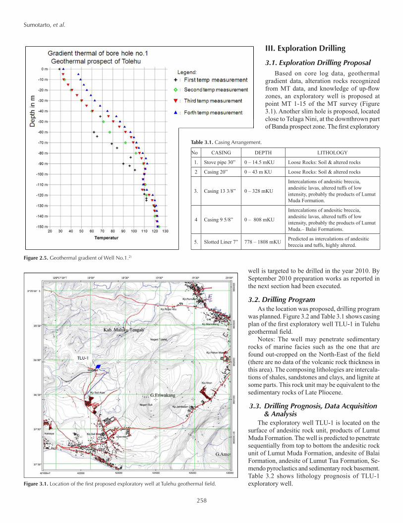
As shown in Figures 2.2 and 2.3, the fluids from the Salahutu mountain block are heated by granodioritic dikes recognized from gravity survey. The heated fluids that are later manifested as mixed warms springs are flowing through and along fractures and perme-able matrix from the fractured volcaniclastic rocks to the southeast of the target area (Banda Prospect) as shown at Telaga Nini. However, it is speculated that the deeper and presumably higher temperature convective fluids are flowing into a confined reservoir within the downthrown block capped by altered volcanic-clastics around Banda prospect. The presence of geo-scientific anomalies and an elevated geothermal alteration supports the recommenda-tion for the target point of an exploratory drilling location.
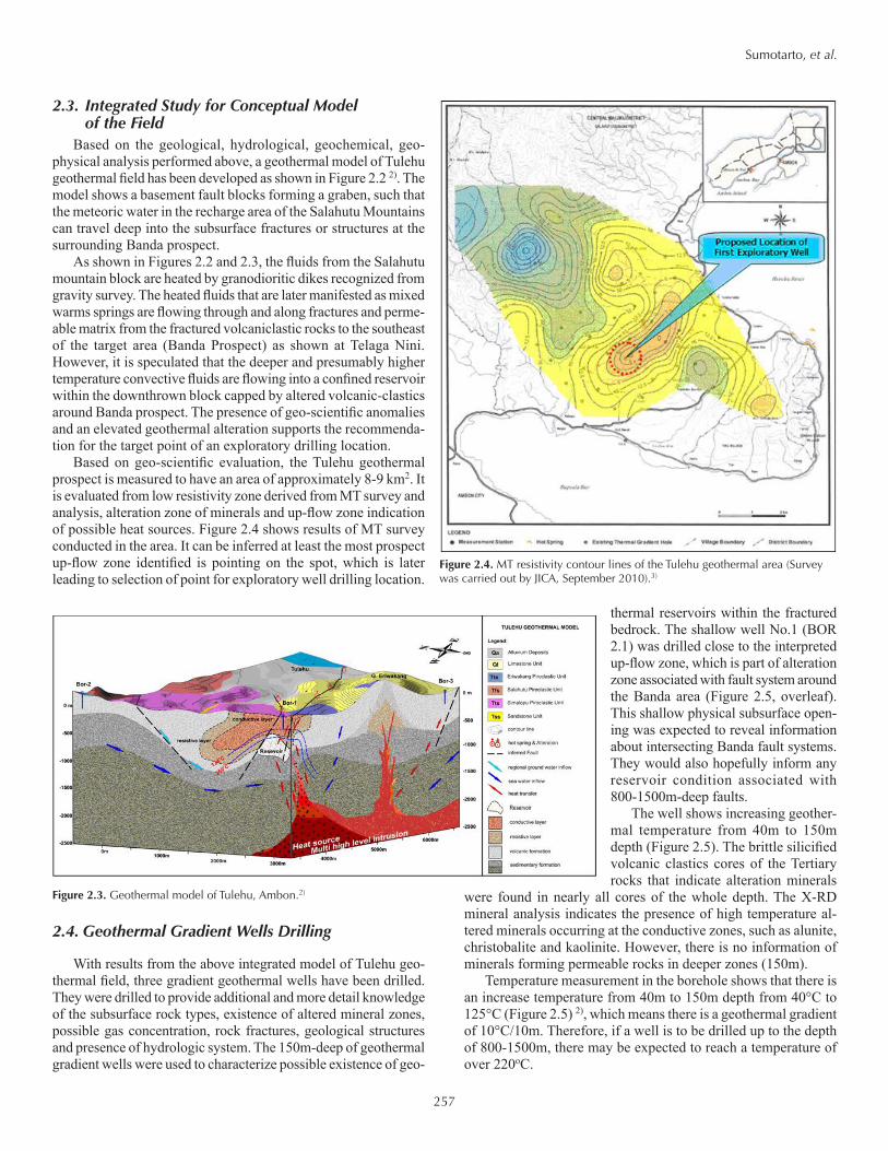
Based on geo-scientific evaluation, the Tulehu geothermal prospect is measured to have an area of approximately 8-9 km2. It is evaluated from low resistivity zone derived from MT survey and analysis, alteration zone of minerals and up-flow zone indication of possible heat sources. Figure 2.4 shows results of MT survey conducted in the area. It can be inferred at least the most prospect up-flow zone identified is pointing on the spot, which is later leading to selection of point for exploratory well drilling location.
2.4. Geothermal Gradient Wells Drilling
With results from the above integrated model of Tulehu geo-thermal field, three gradient geothermal wells have been drilled. They were drilled to provide additional and more detail knowledge of the subsurface rock types, existence of altered mineral zones, possible gas concentration, rock fractures, geological structures and presence of hydrologic system. The 150m-deep of geothermal gradient wells were used to characterize possible existence of geo-
thermal reservoirs within the fractured bedrock. The shallow well No.1 (BOR 2.1) was drilled close to the interpreted up-flow zone, which is part of alteration zone associated with fault system around the Banda area (Figure 2.5, overleaf). This shallow physical subsurface open-ing was expected to reveal information about intersecting Banda fault systems. They would also hopefully inform any reservoir condition associated with 800-1500m-deep faults.
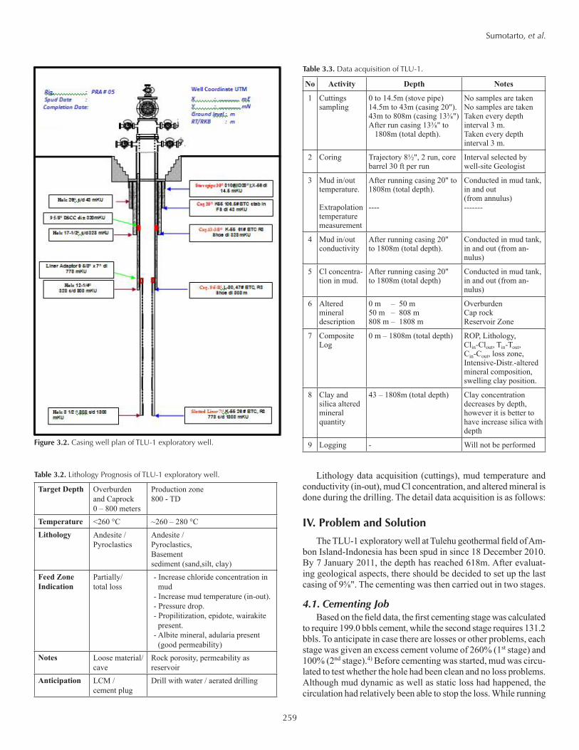
The well shows increasing geother-mal temperature from 40m to 150m depth (Figure 2.5). The brittle silicified volcanic clastics cores of the Tertiary rocks that indicate alteration minerals
were found in nearly all cores of the whole depth. The X-RD mineral analysis indicates the presence of high temperature al-tered minerals occurring at the conductive zones, such as alunite, christobalite and kaolinite. However, there is no information of minerals forming permeable rocks in deeper zones (150m).
Temperature measurement in the borehole shows that there is an increase temperature from 40m to 150m depth from 40°C to 125°C (Figure 2.5) 2), which means there is a geothermal gradient of 10°C/10m. Therefore, if a well is to be drilled up to the depth of 800-1500m, there may be expected to reach a temperature of over 220oC.
Figure 2.3. Geothermal model of Tulehu, Ambon.2)
Figure 2.4. MT resistivity contour lines of the Tulehu geothermal area (Survey was carried out by JICA, September 2010).3)
258
Sumotarto, et al.
III. Exploration Drilling
3.1. Exploration Drilling ProposalBased on core log data, geothermal
gradient data, alteration rocks recognized from MT data, and knowledge of up-flow zones, an exploratory well is proposed at point MT 1-15 of the MT survey (Figure 3.1). Another slim hole is proposed, located close to Telaga Nini, at the downthrown part of Banda prospect zone. The first exploratory
well is targeted to be drilled in the year 2010. By September 2010 preparation works as reported in the next section had been executed.
3.2. Drilling ProgramAs the location was proposed, drilling program
was planned. Figure 3.2 and Table 3.1 shows casing plan of the first exploratory well TLU-1 in Tulehu geothermal field.
Notes: The well may penetrate sedimentary rocks of marine facies such as the one that are found out-cropped on the North-East of the field (there are no data of the volcanic rock thickness in this area). The composing lithologies are intercala-tions of shales, sandstones and clays, and lignite at some parts. This rock unit may be equivalent to the sedimentary rocks of Late Pliocene.
3.3. Drilling Prognosis, Data Acquisition & Analysis
The exploratory well TLU-1 is located on the surface of andesitic rock unit, products of Lumut Muda Formation. The well is predicted to penetrate sequentially from top to bottom the andesitic rock unit of Lumut Muda Formation, andesite of Balai Formation, andesite of Lumut Tua Formation, Se-mendo pyroclastics and sedimentary rock basement. Table 3.2 shows lithology prognosis of TLU-1 exploratory well.
Figure 2.5. Geothermal gradient of Well No.1.2)
Figure 3.1. Location of the first proposed exploratory well at Tulehu geothermal field.
2 Casing 20” 0 – 43 m KU Loose Rocks: Soil & altered rocks
3. Casing 13 3/8” 0 – 328 mKU
Intercalations of andesitic breccia, andesitic lavas, altered tuffs of low intensity, probably the products of Lumut Muda Formation.
4 Casing 9 5/8” 0 – 808 mKU
Intercalations of andesitic breccia, andesitic lavas, altered tuffs of low intensity, probably the products of Lumut Muda.– Balai Formations.
5. Slotted Liner 7” 778 – 1808 mKU Predicted as intercalations of andesitic breccia and tuffs, highly altered.
259
Sumotarto, et al.
Lithology data acquisition (cuttings), mud temperature and conductivity (in-out), mud Cl concentration, and altered mineral is done during the drilling. The detail data acquisition is as follows:
IV. Problem and Solution
The TLU-1 exploratory well at Tulehu geothermal field of Am-bon Island-Indonesia has been spud in since 18 December 2010. By 7 January 2011, the depth has reached 618m. After evaluat-ing geological aspects, there should be decided to set up the last casing of 9⅝". The cementing was then carried out in two stages.
4.1. Cementing JobBased on the field data, the first cementing stage was calculated
to require 199.0 bbls cement, while the second stage requires 131.2 bbls. To anticipate in case there are losses or other problems, each stage was given an excess cement volume of 260% (1st stage) and 100% (2nd stage).4) Before cementing was started, mud was circu-lated to test whether the hole had been clean and no loss problems. Although mud dynamic as well as static loss had happened, the circulation had relatively been able to stop the loss. While running
Figure 3.2. Casing well plan of TLU-1 exploratory well.
Table 3.3. Data acquisition of TLU-1.
No Activity Depth Notes
1 Cuttings sampling
0 to 14.5m (stove pipe)14.5m to 43m (casing 20").43m to 808m (casing 13⅜")After run casing 13⅜" to 1808m (total depth).
No samples are takenNo samples are takenTaken every depth interval 3 m.Taken every depth interval 3 m.
2 Coring Trajectory 8½", 2 run, core barrel 30 ft per run
Interval selected by well-site Geologist
3 Mud in/out temperature.
Extrapolation temperature measurement
After running casing 20" to 1808m (total depth).
----
Conducted in mud tank, in and out (from annulus)-------
4 Mud in/out conductivity
After running casing 20" to 1808m (total depth).
Conducted in mud tank, in and out (from an-nulus)
5 Cl concentra- tion in mud.
After running casing 20" to 1808m (total depth)
Conducted in mud tank, in and out (from an-nulus)
6 Altered mineral description
0 m – 50 m50 m – 808 m808 m – 1808 m
OverburdenCap rockReservoir Zone
7 Composite Log
0 m – 1808m (total depth) ROP, Lithology, Clin-Clout, Tin-Tout, Cin-Cout, loss zone, Intensive-Distr.-altered mineral composition, swelling clay position.
8 Clay and silica altered mineral quantity
43 – 1808m (total depth) Clay concentration decreases by depth, however it is better to have increase silica with depth
9 Logging - Will not be performed
Table 3.2. Lithology Prognosis of TLU-1 exploratory well.
Target Depth Overburden and Caprock0 – 800 meters
Production zone 800 - TD
Temperature <260 °C ~260 – 280 °CLithology Andesite /
- Increase mud temperature (in-out).- Pressure drop.- Propilitization, epidote, wairakite
present.- Albite mineral, adularia present
(good permeability)Notes Loose material/
caveRock porosity, permeability as reservoir
Anticipation LCM / cement plug
Drill with water / aerated drilling
260
Sumotarto, et al.
the cementing job, however, losses had occurred again. The mud to be used to push the cement slurry had lost totaling 127 bbls. At this first cementing stage it was reported that there was a partial loss where totally 49 bbls of fluids had been lost. At this point there was no report on sign or indicator on what level the top ce-ment of the first stage had reached, although the cement top had apparently reached the DSCC, near casing shoe of 13⅜" casing pipe. Figure 4.1 shows stages of the cementing job. 4)
Before starting second stage cementing job, a mud circulation was carried out via DSCC ports. It was spotted that there was a mud dynamic loss of 2-2.5 BPM. The second stage cementing was then carried out. With the fluid loss of 49 bbls at the first cementing stage and a dynamic mud loss of 2-2.5 BPM before the second stage cementing job, it should be notified that it could cause any problems later. As the second stage cementing job was finished with total designed cement volume including the excess volume that had been prepared, it was realized that the top cement of this stage did not reach the surface. It was then decided to perform top cementing job in order to complete the cement-ing job i.e. filling the annulus between 13⅜" and 9⅝ casing pipe up to the surface. The problem was then aroused because the depth of the top cement was not clearly identified. Again there were no signs or indicators on where the depth of the top cement of this second stage cementing job. A macaroni pipe was inserted in the annulus to measure the depth of top cement level and to do top cementing job. However, at the depth of 37 m the macaroni pipe was stuck, it could not move down any further. This is probably due to the centralizers or pipe joints that were on the 9⅝" casing pipe.
With the above problem the drilling has been ceased temporarily. Drilling analysis performed by the field as well as office crews ended with the results on the opin-ion that the top second stage cement had only reached at depth of approximately 200 m. This could be the case because as explained above, while doing the first stage cementing job, there was a partial loss problem. Cement slurry had lost at least as much as 49 bbls. This had aroused a suspicion that the top cement had not reached the casing shoe of 13⅜" casing pipe. The second stage cement job probably had to make up the lost or filling up the 12¼" hole to the 13⅜"shoe level. The mud dynamic loss of 2-2.5 BPM occurred just before the start of the second stage cementing job could also cause the cement slurry loss problem on the second stage cementing job. This could severe the difficulty in detecting the depth of the top cement level between 13⅜" and 9⅝" casing pipes.
4.2. Alternative SolutionsSince the drilling has been ceased, the drilling contractor had
been on the opinion that drilling could be continued although the cementing job was not perfect, i.e. there was an un-cemented part particularly in the annulus of between 13⅜" and 9⅝" casing pipes. If cementing top job is forced to be carried out, there is a fear that there could be water trapped in the 13⅜" and 9⅝" casing annulus. Otherwise, when the well is heated later, the trapped water could cause any further problems. There were happenstances in Kamo-
jang and Lahendong geothermal fields (Indonesia) in the past that that kind of problem had caused geothermal wells blow outs and casing collapses. The wells were then abandoned.
On the other hand, the field owner (PT.PLN Geothermal) was on the opinion that the cementing, particularly the second stage, should be completed first before drilling is to be continued. The company fears and should anticipate that if the drilling is to be continued, the un-cemented 9⅝" casing pipe could vibrate severely and break down. The company proposes a CBL job first to locate the top cement level, and then fill up the 13⅜" and 9⅝" casing annulus with cement or any other material such as coarse sand
or gravel that could support to make the 9⅝" casing pipe stable. The job could be carried from the surface of 13⅜" and 9⅝" cas-ing annulus.
4.3. Precaution Steps Preceding Top Cementing JobAfter a hard struggle, there could be measured that the ce-
ment top in the annulus between casing pipe 9⅝" and 13⅜" had only reached up the depth of 244 m. Although some steps of the top cementing procedure has been reached, however the job was not easily carried out. After carrying out the measurement of the depth of the cement top, the work continued to drain water existing above the cement top. Because of the limiting stock of material, the drilling company had to ship small diameter pipes of ⅜" and ¼"-OD to facilitate water draining and possible cementing jobs. The short pipe of 6m sizes had to be connected in the drilling site to make up 18 meter long pipe segments before slipping them into the 9⅝" and 13⅜" annulus.
With extra efforts, three macaroni pipes were able to be slipped into the 9⅝" and 13⅜" annulus. The pipe strings were made up of 18m shorter sizes prepared before that were connected by welding them on the joints. The tip of macaroni pipes could reach a depth of at 239m, 235m and 226m each. This is intended to being able draining water gradually. Every pipe was pressure tested each time
Figure 4.1. Stages of 13⅜" – 9⅝" Casing Cementing Job.
261
Sumotarto, et al.
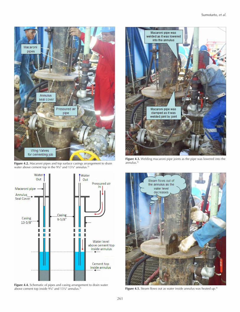
Figure 4.2. Macaroni pipes and top surface casings arrangement to drain water above cement top in the 9⅝" and 13⅜" annulus.5)
Figure 4.3. Welding macaroni pipe joints as the pipe was lowered into the annulus.5)
Figure 4.4. Schematic of pipes and casing arrangement to drain water above cement top inside 9⅝" and 13⅜" annulus.5) Figure 4.5. Steam flows out as water inside annulus was heated up.5)
262
Sumotarto, et al.
it was lowered into the annulus by adding 18m segment. The test was carried out by blowing in air to make sure there are no plugs and leaks on the joints along the string. As the macaroni pipes finished the testing at the deepest level it could reach, the annulus was then sealed with metal cover (Figure 4.2 and 4.3).5) At least three trials of setting in and pulling out the macaroni pipes were performed because of the failures due to imperfect weld-ing, i.e. leaks and fractures or plugging material inside the string. The water was then drained by compressing with pressured air through the 9⅝" and 13⅜" annulus, letting the water flow out of the macaroni pipes (Figure 4.4). While draining out the water, steam flows periodi-cally from inside the annulus (Figure 4.5). This is a sign that the water level inside the annulus was decreasing, while the lower part of the annulus was getting hotter. After letting the water drained till the last drop, the air flow was continued to steam up the remaining water and finally making sure the water has been completely removed from inside annulus.
4.4. Top Cementing JobAlthough small macaroni pipes of ⅜" and ¼" have
been able to be slipped into the 9⅝" and 13⅜" annulus (Figure 4.4), however the cementing job could not be carried out there after right away. The conduit of small diameter macaroni pipes were not enough wide to flow cement slurry. This even harder to do so because as the water was drained, the casing pipes started to heat up. A measure of 94°C temperature at the casing top surface revealed interpretation that the possible down-hole annulus temperature could reach as high as 150°C. If this is true, cement slurry would easily dry even if it flows through wide open-ing conduit such as the 9⅝" and 13⅜" annulus. Thus, the flow of cement slurry through macaroni pipes could be easily jammed and eventually plugged the string.
With careful design such as the use of proper cement retarder the cementing company, under the authority of the drilling com-pany, was able to create cement slurry that can cope with high temperature without fast drying before reaching the depth of up to 244m, the depth of cement top. Considering the difficulty and risks of flowing cement slurry through macaroni pipes, it was decided the cement slurry was finally to be flown gravitationally through the 9⅝" and 13⅜" casing annulus via one of two 3⅛" wing valves installed on top of 13⅜" casing (Figure 4.6). The other wing valve was used to release air. Two stages of slurry injections were inter-fered with air compression under 3000 psig pressure to make sure the cement is bonded properly. First cement injection was able to fill 10 bbls, while the second round was 36 bbls, totaling 46 bbls.
V. Conclusions
In order to finish the cementing job, the field owner (PT.PLN Geothermal) and the drilling contractor had been going through exhausting procedures. Additional material had to be shipped to the drilling site. As required small size (macaroni) pipes ar-rived on the site, long lasting work of pipe connection, slipping into the annulus, and draining water out of the annulus has to be done before conducting the top cementing job that has been
left uncompleted. Water was drained through macaroni pipes by compressing air into the 9⅝" and 13⅜" annulus. Cement slurry was then injected to flow gravitationally through wing valves. Al-though PT.PLN Geothermal and the drilling contractor had been facing tough and difficult problems in furnishing the procedure, with a whole intense efforts and careful handling, the cementing job was finally done.
Acknowledgements
The authors would like to express their deepest gratitude to PT.PLN Geothermal management, in particular Mr.Tjahjo Sas-mojo and Mr.Endro Supriyanto, for giving the opportunity and permission to write this paper. Without data, information, and various reports from the beginning of the exploration activities of Tulehu geothermal field it is impossible to materialize the paper. Special thanks are directed to Mr.Syamsu Hamid and Mr.Ahmad Zakky who act as PT.PLN-Geothermal company men who have given permission and guidance during the drilling operation.
References1. Giggenbach, W. F.,1988, Geothermal Solute Equilibria, Derivation of
Na-K-Mg-Ca Geoindicators, Geochimica et Cosmochimica Acta Vol. 52, Pergamon Press Ltd, hal 2749 – 2765.
2. PT PLN (Persero) Maluku dan PISGA Engineer Consultants, 2008, Peker-jaan Pre-Feasibility PLTP Tulehu Untuk Studi Geosain : Final Report.
3. Japan International Cooperation Agency (JICA), 2010, JICA Preparatory Survey For Tulehu Geothermal Power Plant, Temporary Draft Final Report.
4. PT.PLN Geothermal: TLU-1 Exploratory Drilling, Weekly Report to JICA 17 January 2011.
5. PT.PLN Geothermal: TLU-1 Exploratory Drilling, Weekly Report to JICA 24 January 2011.
Figure 4.6. Schematic of cementing job inside the 9⅝" and 13⅜" annulus.5)