NOTICE OF ANTICIPATED UPCOMING SOLICITATION: “Metromover Comprehensive Wayside System Rejuvenation Project” For MIAMI-DADE COUNTY Department of Transportation and Public Works SOLICITATION AND PROCUREMENT PROCESS ADMINISTERED BY: INTERNAL SERVICES DEPARTMENT - STRTEGIC PROCUREMENT DIVISION The Following Draft Documents are provided for Industry Review and Comment: 1) Draft Solicitation Special Provisions 2) Draft Technical Provisions NOTE: The County requests industry review and feedback from interested parties. To facilitate this process, please submit the attached Notice of Interest form as instructed.
Transcript
NOTICE OF ANTICIPATED UPCOMING SOLICITATION:
“Metromover Comprehensive Wayside System Rejuvenation Project”
For
MIAMI-DADE COUNTY
Department of Transportation and Public Works
SOLICITATION AND PROCUREMENT PROCESS ADMINISTERED BY:
INTERNAL SERVICES DEPARTMENT - STRTEGIC PROCUREMENT DIVISION
The Following Draft Documents are provided for Industry Review and
Comment:
1) Draft Solicitation Special Provisions
2) Draft Technical Provisions
NOTE: The County requests industry review and feedback from
interested parties. To facilitate this process, please submit the attached
Notice of Interest form as instructed.
NOTICE OF INTEREST
“Metromover Comprehensive Wayside System Rejuvenation Project”
1. Please return this form by February 26, 2019 to: Fred Simmons, Jr. CPPO
Email: Simmons Jr, Fred (ISD) [email protected] The County is interested to receive industry feedback regarding the technical and some commercial
aspects of work detailed in the attached documents for the upcoming solicitation. It is the County’s intent
to meet with each interested potential proposer that expresses specific interest in providing feedback on
the documents provided. The County will schedule individual meeting session (2 hours) with interested
parties to review and discuss any feedback provided, prior to a solicitation document being advertised.
When submitting this form, please provide a brief summary of the areas feedback will be provided.
Through discussion with interested parties, the County will consider information received from any
feedback sessions for inclusion in the solicitation. The County makes no claim that all feedback
information provided will be included in a solicitation. Rather, at the County’s discretion, information
deemed to be of value to the solicitation may be included.
Potential Proposer shall sign and submit this Notice of Interest form indicating interest in the upcoming
“Metromover Comprehensive Wayside System Rejuvenation Project” solicitation and its willingness to
provide the County feedback on the draft documents provided.
Instructions for parties interested in providing feedback to the County during a two hour meeting session
at a designated County location in downtown Miami, Florida. Interested parties will be contacted by the
County with meeting particulars; date time, etc.
1) Sign this form.
2) Provide contact information:
a. Print Contact name:
b. Email address and phone number where the interested party can be reached during
regular County business hours; 8 a.m. thru 5 p.m. Eastern Time, Monday through Friday.
METROMOVER REJUVENATION PROJECT D R A F T SPECIAL PROVISIONS
Lea+Elliott, Inc. SP i Metromover Rejuvenation 100%+ Draft
December 2018
This document contains intellectual property copyrighted by Lea+Elliott. No part of these documents may be copied in whole or in part without written permission from Lea+Elliott, Inc.
6.1.13 Support for Public Information ........................................................... 8-15
METROMOVER REJUVENATION PROJECT D R A F T SPECIAL PROVISIONS
Lea+Elliott, Inc. SP ii Metromover Rejuvenation 100%+ Draft
December 2018
This document contains intellectual property copyrighted by Lea+Elliott. No part of these documents may be copied in whole or in part without written permission from Lea+Elliott, Inc.
6.5.6 Rule Book ............................................................................................ 8-36
6.5.7 Training Program ................................................................................ 8-37
6.5.8 Form and Updates of Plans and Manuals ........................................... 8-39
METROMOVER REJUVENATION PROJECT D R A F T SPECIAL PROVISIONS
Lea+Elliott, Inc. SP iii Metromover Rejuvenation 100%+ Draft
December 2018
This document contains intellectual property copyrighted by Lea+Elliott. No part of these documents may be copied in whole or in part without written permission from Lea+Elliott, Inc.
METROMOVER REJUVENATION PROJECT D R A F T SPECIAL PROVISIONS
Lea+Elliott, Inc. SP iv Metromover Rejuvenation 100%+ Draft
December 2018
This document contains intellectual property copyrighted by Lea+Elliott. No part of these documents may be copied in whole or in part without written permission from Lea+Elliott, Inc.
8.3.1.1 Waiver of Tests ..................................................................... 10-18
8.3.1.2 For Contract Compliance ...................................................... 10-18
8.3.2 Factory Test and Inspection .............................................................. 10-19
METROMOVER REJUVENATION PROJECT D R A F T SPECIAL PROVISIONS
Lea+Elliott, Inc. SP v Metromover Rejuvenation 100%+ Draft
December 2018
This document contains intellectual property copyrighted by Lea+Elliott. No part of these documents may be copied in whole or in part without written permission from Lea+Elliott, Inc.
9.2.4 Notification of Contractor Delay ......................................................... 11-3
9.2.5 Strikes of Contractor's Personnel ....................................................... 11-3
9.3 TIME EXTENSIONS FOR UNUSUALLY SEVERE WEATHER ................................... 11-4
12.3.2 Negotiated or Directed Price Adjustment .......................................... 14-3
METROMOVER REJUVENATION PROJECT D R A F T SPECIAL PROVISIONS
Lea+Elliott, Inc. SP vi Metromover Rejuvenation 100%+ Draft
December 2018
This document contains intellectual property copyrighted by Lea+Elliott. No part of these documents may be copied in whole or in part without written permission from Lea+Elliott, Inc.
METROMOVER REJUVENATION PROJECT D R A F T SPECIAL PROVISIONS
Lea+Elliott, Inc. SP 1-1 Metromover Rejuvenation 100%+ Draft
December 2018
This document contains intellectual property copyrighted by Lea+Elliott. No part of these documents may be copied in whole or in part without written permission from Lea+Elliott, Inc.
1 INTRODUCTION
These Special Provisions include requirements that supplement the General Provisions document.
Specific references are made to the American Society of Civil Engineers (ASCE) Automated People Mover (APM) Standards (ASCE 21-13). These are available from the ASCE. In the event of a conflict between any of these ASCE APM Standards and the requirements of the specific sections of the Special Provisions and the Technical Provisions the requirements of the specific sections of the Special Provisions and the Technical Provisions shall govern.
The Contractor represents and certifies that the Work shall be performed in a good and workmanlike manner and shall conform to the highest standards of the engineering and transit industry practice observed on successfully completed, large, complex projects by the Contractor and transit system/equipment suppliers of similar stature and reputation as the Contractor.
As specified in Section XXX of the Instructions to Proposers (ITP), any conditions, exceptions, reservations or understandings to the provisions of the Contract Documents that were not explicitly, fully and separately stated in the Contractor’s Proposal using the format of Appendix 4 to the ITP and accepted by the County shall be invalid and shall not be binding on the County.
References to specific documents are made as follows:
ITP Section x: Section No. x of the Instructions to Proposers
GC Article x: Section No. x of the General Provisions of the Design/Build Contract
TP Section x: Section No. x of the Technical Provisions of the Design/Build Contract
SP Section x: Section No. x of the Special Provisions of the Design/Build Contract
PF Section x: Section No x of the Pricing Forms
Any reference to a specific section of a Contract document shall also include any subsection that may be contained in the referenced section.
METROMOVER REJUVENATION PROJECT D R A F T SPECIAL PROVISIONS
Lea+Elliott, Inc. SP 3-1 Metromover Rejuvenation 100%+ Draft
December 2018
This document contains intellectual property copyrighted by Lea+Elliott. No part of these documents may be copied in whole or in part without written permission from Lea+Elliott, Inc.
2 DEFINITIONS, TERMS AND ABBREVIATIONS
Definitions and abbreviations that apply to terms used in the Contract Documents are included in General Conditions- Article 1. Additional definitions are provided in Section 1.5, Definitions, of the ASCE APM Standards. Additional definitions and acronyms for organizations, codes and standards are given in TP Section 21. Where there is a conflict between definitions in the referenced ASCE standard and those provided in the Special Provisions and Technical Provisions, the Special Provisions and Technical Provisions shall apply.
3 STATEMENT OF WORK
The general scope of the Contractor’s Work is presented in SP Section 3.1.1, TP Section 3.1.1 and defined in detail in the Technical Provisions and the Contractor’s Proposal. The responsibilities of the County for the Work are provided in SP Section 3.1.2.
3.1 WORK SCOPE
This Contract covers the complete design, fabrication, assembly, factory testing, construction, installation and on-site integration, test and demonstration and implementation of the Project, beginning with the Notice to Proceed (NTP), and ending with the completed, ready-to-operate System. During this period, the County has retained certain responsibilities as hereinafter defined.
3.1.1 Contractor’s Responsibilities
The Contractor shall perform all of the Project management, quality assurance, design, analysis, documentation, construction, supply, fabrication, shipping, expediting, storing of materials, removal of equipment to be rejuvenated, installation, erection, debugging, testing and demonstration of facilities, material and equipment required to deliver an operable, safe, reliable, and sustainable System in conformance with all the requirements of this Contract and the Contractor’s Proposal. The Contractor shall be solely responsible for delivering all aspects of the Work; and integrating the Operating System and the Fixed Facilities Work into a fully functional System, meeting all of the requirements of the Contract.
Contractor is responsible for the removal and disposal of existing equipment pertaining to the Contractor’s scope of work. The Contractor is to identify as part of the Cut-over Plan (CDRL) the equipment to be removed.
The Contractor shall be responsible for identifying and rectifying with the County any conflicting requirements within the Contract Documents, codes, standards, ordinances, rules and regulations. Where a conflict may exist among the Contract requirements, the more stringent requirement will be applied. Where conflicts are identified that require clarification, the Contractor shall notify the County in writing, describing in detail the conditions noted. The
METROMOVER REJUVENATION PROJECT D R A F T SPECIAL PROVISIONS
Lea+Elliott, Inc. SP 3-2 Metromover Rejuvenation 100%+ Draft
December 2018
This document contains intellectual property copyrighted by Lea+Elliott. No part of these documents may be copied in whole or in part without written permission from Lea+Elliott, Inc.
County will provide the Contractor with a written response including directions to resolve the conflicting information. This direction shall be final.
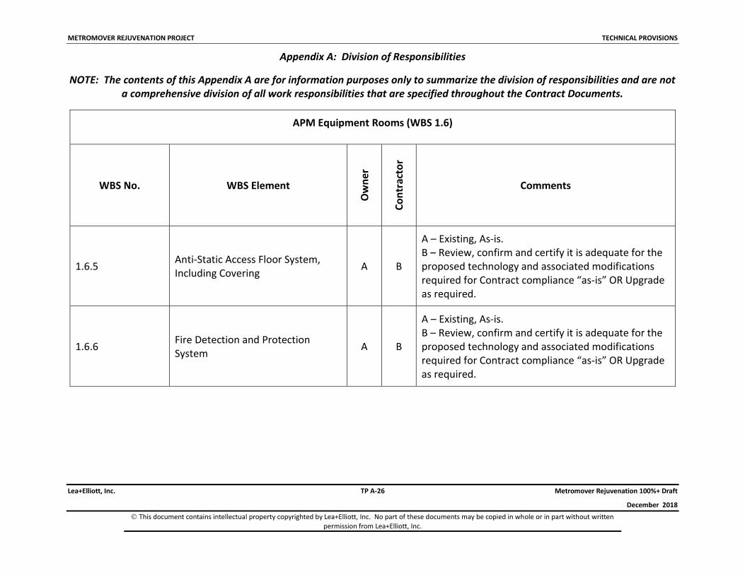
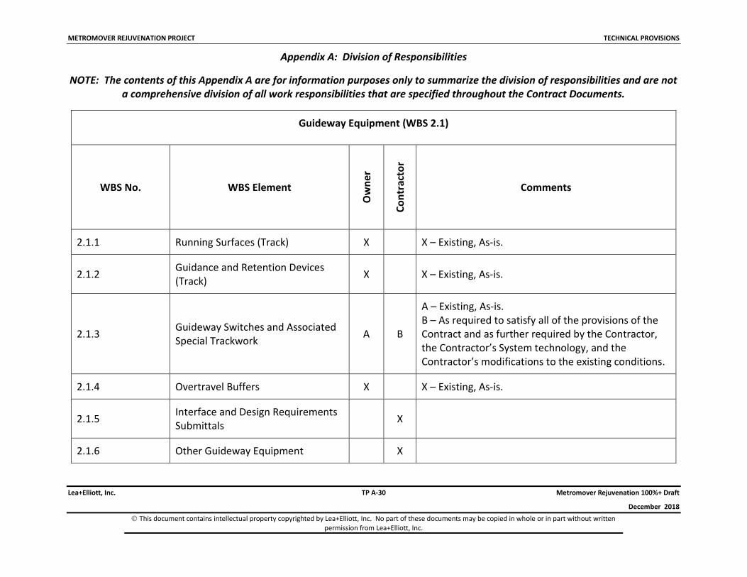
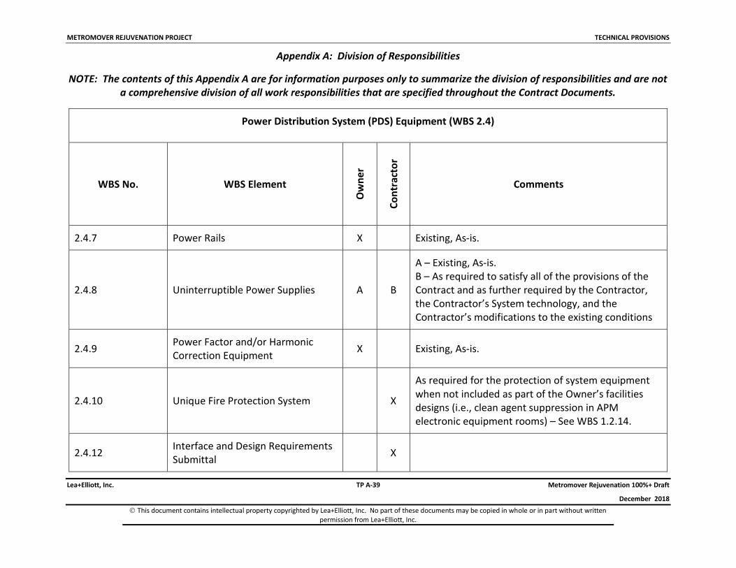
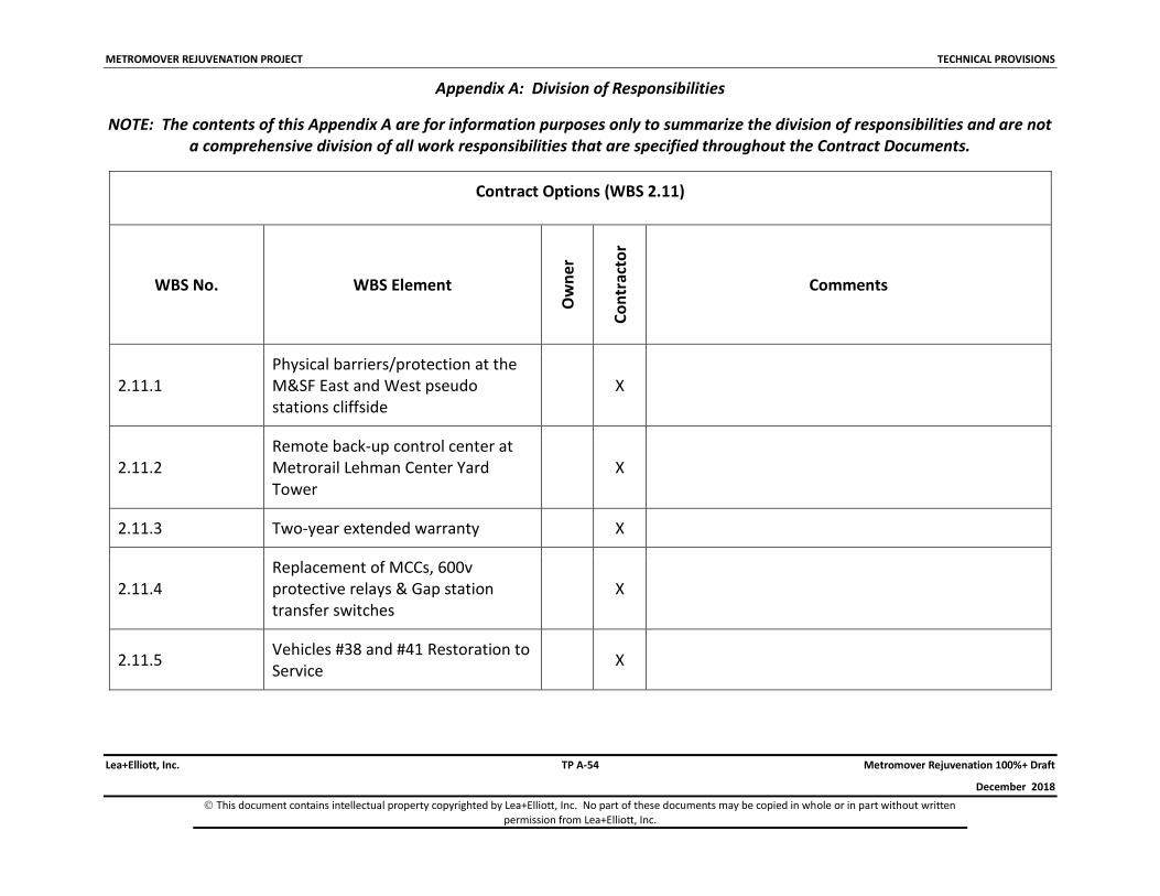
A listing of the Contractor’s responsibilities for the Work is provided in Appendix A to the Technical Provisions. This listing is of a general nature, intended to define the division of Work responsibilities between the Contractor and the County. The Work is defined in greater detail throughout the Contract Documents.
All Contractor personnel must be approved by the County for access to County facilities. Contractor personnel must ware, visually conspicuous, Contractor identification and may be required to undergo clearance measures that may include background checks to ensure e Contractor personnel conform to the requirements of Article _ of the County General Terms and Conditions.
3.1.2 County’s Responsibilities
The County will have certain responsibilities related to the Work. In completing these responsibilities, the County may elect to involve the participation of design professionals and construction contractors who will not be under subcontract to the Contractor but will be separately contracted with the County. All interfacing between the Contractor and each such other entity will be arranged and managed by the County. The Work of the Contractor and the Work of any County contractors will be reflected in the mutually developed Project Master Schedule for the information of all parties. The Project Master Schedule shall be mutually developed by the parties, maintained by the Contractor and approved by the County.
A listing of the County’s responsibilities for the Work is provided in Appendix A to the Technical Provisions. This listing is of a general nature, intended to define the division of Work responsibilities between the Contractor and the County. The Work is defined in greater detail throughout the Contract Documents.
METROMOVER REJUVENATION PROJECT D R A F T SPECIAL PROVISIONS
Lea+Elliott, Inc. SP 4-1 Metromover Rejuvenation 100%+ Draft
December 2018
This document contains intellectual property copyrighted by Lea+Elliott. No part of these documents may be copied in whole or in part without written permission from Lea+Elliott, Inc.
4 PROJECT WORK SCHEDULE
The Contractor shall develop a Work schedule considering all the constraints identified in the Contract Documents.
4.1 The time schedule for the Work is critical, and liquidated damages shall be as prescribed in the contract document(sNOTICE TO PROCEED
Notice to Proceed (NTP) for design, fabrication, installation, integration, test and demonstration of the System will be provided by the County after all of the Contract Documents are properly completed and executed by the Contractor, approved by the Board of County Commissioners and administratively executed by the County.
4.2 AVAILABILITY DATES
Metromover facilities such as Equipment Rooms, Substations, Central Control, Guideway, M&SF will generally be available to the Contractor from the start of the project provided such availability does not impact passenger service. Potential impact on passenger service will be determined solely by the County.
The Contractor shall be required to formally request access to the Metromover facilities using the County’s established process and forms (Daily track request allocation request form, etc.). Contractor shall coordinate with the County on the dates and times for which access is requested at least five (5) business days in advance of the requested access date.
In the event the Contractor does not formally submit an access request to the County within the required timeframe above, the County shall not be accountable for delays in System delivery by the Contractor if the County does not grant access to the Metromover facilities.
4.3 TIME FOR COMPLETION
The County anticipates Project completion within 48 months from NTP. See SP Section 8.7.1 regarding the requirements for Substantial Completion. The Project Plan as submitted by the Proposer will be negotiated to reflect a revised Contract Project Plan that will be used to track project progress; task completion, and payment obligations of the County.
The time for completion of the Work will be adjusted, if found necessary by the County, in accordance with applicable sections of the Contract Documents.
4.4 OTHER SCHEDULES
Specific deadlines for Contractor submittals are provided in SP Sections 6.1.5 and 11. The Contractor is required to prepare and submit a Network Analysis for acceptance by the County, as provided in SP Section 6.1.2. This Network Analysis will be a detailed schedule and the basis for assessing and controlling progress. The Contractor shall not begin any Work, at any time,
METROMOVER REJUVENATION PROJECT D R A F T SPECIAL PROVISIONS
Lea+Elliott, Inc. SP 4-2 Metromover Rejuvenation 100%+ Draft
December 2018
This document contains intellectual property copyrighted by Lea+Elliott. No part of these documents may be copied in whole or in part without written permission from Lea+Elliott, Inc.
without written acceptance of the Network Analysis by the County. However, the County shall not withhold such acceptance (1) without just cause or (2) as a means to delay the availability of property identified in SP Section 4.2 above.
METROMOVER REJUVENATION PROJECT D R A F T SPECIAL PROVISIONS
Lea+Elliott, Inc. SP 7-1 Metromover Rejuvenation 100%+ Draft
December 2018
This document contains intellectual property copyrighted by Lea+Elliott. No part of these documents may be copied in whole or in part without written permission from Lea+Elliott, Inc.
5 ASSUMPTION, PARAMETERS, PROJECTIONS, ESTIMATES AND EXPLANATIONS
6 THE CONTRACTOR UNDERSTANDS AND AGREES THAT ANY ASSUMPTIONS, PARAMETERS, PROJECTIONS, ESTIMATES AND EXPLANATIONS PRESENTED BY THE COUNTY WERE PROVIDED TO THE CONTRACTOR FOR EVALUATION PURPOSES ONLY. HOWEVER, SINCE THESE ASSUMPTIONS, PARAMETERS, PROJECTIONS, ESTIMATES AND EXPLANATIONS REPRESENT PREDICTIONS OF FUTURE EVENTS THE COUNTY MAKES NO REPRESENTATIONS OR GUARANTEES; AND THE COUNTY SHALL NOT BE RESPONSIBLE FOR THE ACCURACY OF THE ASSUMPTIONS PRESENTED; AND THE COUNTY SHALL NOT BE RESPONSIBLE FOR CONCLUSIONS TO BE DRAWN THEREFROM; AND ANY ASSUMPTIONS, PARAMETERS, PROJECTIONS, ESTIMATES AND EXPLANATIONS SHALL NOT FORM THE BASIS OF ANY CLAIM BY THE CONTRACTOR. THE CONTRACTOR ACCEPTS ALL RISK ASSOCIATED WITH USING THIS INFORMATION.
7 REFERENCE DATA/REFERENCE DRAWINGS
Reference Data and/or Reference Drawings are included in the Contract Documents.
The Contractor is solely responsible for all interpretations, assumptions, deductions, or conclusions that the Contractor may make or derive from the County-furnished Reference Data and Reference Drawings. The County assumes no responsibilities for any understanding reached or representation made, concerning conditions that can affect the Work, by any of its officers, employees, agents or consultants before the execution of the Contract; unless that understanding, or representation is expressly stated in a Contract Document. The County will not adjust any design or cost impacts for errors or omissions by the Contractor with respect to its interpretation of the Reference Data and/or Reference Drawings.
The Contractor is responsible to fully familiarize themselves with the Metromover System and fixed facilities and all other work. Reference Drawings are provided as additional source of reference for Project context only. The County makes no statement as to the accuracy of any as-built documentation provided to the Contractor. The as-built documentation if provided in the Reference Data for general informational reference only. The Contractor is solely responsible to verify all existing conditions.
Contractor shall investigate and obtain any additional information, data and drawing as necessary for the performance of its work.
METROMOVER REJUVENATION PROJECT D R A F T SPECIAL PROVISIONS
Lea+Elliott, Inc. SP 8-1 Metromover Rejuvenation 100%+ Draft
December 2018
This document contains intellectual property copyrighted by Lea+Elliott. No part of these documents may be copied in whole or in part without written permission from Lea+Elliott, Inc.
8 PROJECT MANAGEMENT
8.1 MANAGEMENT PROGRAM & ORGANIZATION
The Contractor shall be responsible for the total management of the Work under this Contract, pursuant to the terms and conditions hereof. The Contractor shall be responsible for establishing the required organization and procedures and providing personnel and supporting equipment/facilities to ensure that the Project is completed within the time schedule set forth herein. These Contractor responsibilities shall apply from the Notice to Proceed for until completion of the Work and Final Acceptance of the System by the County.
The key members of the Contractor's Project management team shall each be experienced in the activities of their assigned roles. Experience with the specific technology proposed must be embodied in the Project management team. All key members of the Project management team shall be able to adequately communicate in the English language.
The Contractor, individuals and/or entities constituting the Contractor and the officers or directors of the Proposer or entities, or key members of the Project management team shall have a record of past performance sufficient to ensure that they have the experience, competence and integrity to successfully complete a Contract of this magnitude. These requirements must be identified and demonstrated in the Proposer’s response to the solicitation, and must be approved by the County for the Work efforts to be provided.
The Contractor shall have, as a part of its team, an architectural/engineering/manufacturing organization that is skilled in all disciplines required for the Work, of sufficient size and availability. Design facilities shall be fully equipped to assure Work will progress on schedule.
The Contractor shall have in-place a parts replacement and repair support organization that is readily available to support operational testing and system demonstration during the life of the Metromover Project.
All communications, whether oral or written, reports, drawings and documentation, concerning or in any way related to this Contract shall be in the American English language according to Webster’s New Collegiate Dictionary, G. & C. Merriman Co. The system of units used in all reports and analyses (e.g., weights, measures, forces, pressures, stresses, energy, power quantities, heat quantities, etc.) and all design that is unique to the System shall be as commonly used in the United States (i.e., English units). The primary system of units shown in all documentation and drawings that are not unique to the System shall be the system of units in which the design was originally carried out, with applicable equivalents in English (or metric units, as appropriate) shown in parentheses.
All of the Contractor's activities shall be under the direction of its Project Manager who shall be the principal contact between the Contractor and the County. The County shall have the right to accept (or reject) the Contractor's Project Manager and individual members of the key
METROMOVER REJUVENATION PROJECT D R A F T SPECIAL PROVISIONS
Lea+Elliott, Inc. SP 8-2 Metromover Rejuvenation 100%+ Draft
December 2018
This document contains intellectual property copyrighted by Lea+Elliott. No part of these documents may be copied in whole or in part without written permission from Lea+Elliott, Inc.
management and technical staff at any time during the Contract. Any such rejected Project Manager or key management or technical staff person shall be immediately removed from the Project and replaced with a person who possess the requisite knowledge, skills and experience acceptable to the County. Also, once the County’s acceptance has been received as aforesaid, no such accepted personnel may, for so long as such personnel remain in the employ of the Contractor or any entity affiliated with the Contractor or its constituent partners or shareholders, be removed from the Project without the prior written consent of the County.
8.1.1 Project Management Plan
In accordance with the Contract Data Requirements List (CDRL), the Contractor shall submit a Project Management Plan to the County for its review and acceptance. The plan shall be consistent with the Federal Transit Administration’s (FTA) Project and Construction Management Guidelines, March 2016; and be an expansion of the plan included in the Contractor's Proposal. Any differences from or changes to this Project Management Plan shall require acceptance by the County. The Project Management Plan shall include, at a minimum the following items:
An organization chart showing the Contractor's organization (including subcontractors' and supplier’s organizations) and explanation of how each entity will be involved, defining their general and project-specific responsibilities and discussing how the individual entities will coordinate their Work.
A listing of key management and technical staff, together with their qualifications, experience, responsibilities and involvement in the Project.
A description of the Contractor's plan for performing the Work.
A complete Work Breakdown Structure (WBS), indicating the source/ responsibility for completing each aspect of the Work. The WBS shall be the basis for organizing all Work under the Contract and shall be reflected in the organization of the Network Analysis, Work Schedule, Submittal Schedule, and Schedule of Values. The WBS shall be consistent with and an expansion of the WBS specified in TP Appendix A.
A preliminary Network Analysis in accordance with SP Section 6.1.2 indicating all Project tasks keyed to the WBS. This preliminary Network Analysis shall include final detail for the first 120 days of, and preliminary information thereafter, for the remainder of the Project.
A preliminary Project Work Schedule in accordance with SP Section 6.1.3 that shall be a firm schedule for all activities in the first 120 days of, and preliminary for activities thereafter. The preliminary Project Work Schedule must show when the County acceptances are needed and incorporate minimum periods for the County review in accordance with SP Section 6.1.3 and SP Section 11.
METROMOVER REJUVENATION PROJECT D R A F T SPECIAL PROVISIONS
Lea+Elliott, Inc. SP 8-3 Metromover Rejuvenation 100%+ Draft
December 2018
This document contains intellectual property copyrighted by Lea+Elliott. No part of these documents may be copied in whole or in part without written permission from Lea+Elliott, Inc.
The preliminary Schedule of Values that was submitted with the Proposal and accepted by the County.
A preliminary Submittal Schedule for all deliverables and Design Review data, as required by SP Section 6.1.5.
A description and outline of the Monthly Progress Report required by SP Section 6.1.7.
A revised and updated CDRL (SP Section 11) consistent with the preliminary Submittal Schedule of item (H) above.
A numbering system and distribution listing for all correspondence and transmittals under this Contract, subject to acceptance by the County and satisfying the requirements of SP Section 6.1.20.
Buy America Compliance (the compliance will be further detailed in the Buy America Compliance Plan.Noted that certain elements of the Project Management Plan are first to be provided as preliminary and updated/expanded as appropriate.
8.1.2 Network Analysis
In accordance with the CDRL, the Contractor shall submit for acceptance by the County a final Network Analysis for, keyed to the WBS using the numbering system of TP Appendix A. The final Network Analysis shall be an expansion of the preliminary Network Analysis submitted with the Project Management Plan. The Contractor shall maintain and update the Network Analysis in accordance with the CDRL showing the actual progress made and any schedule revisions.
The Network Analysis shall be computer based, of the type known as Critical Path Method (CPM) and shall be prepared by the Contractor in accordance with the CPM in Construction Management, by O’Brien and Plotnick, published by McGraw-Hill (Eighth Edition, 2015), and shall satisfy the unique requirements specified in SP Section 6.1.4. The Network Analysis shall include sufficient detail to define each task or activity of design and construction and those items of a critical nature.
Central to the Network Analysis shall be measurable and deliverable milestones for controlling and reporting progress and as a basis for payments consistent with the Schedule of Values. These milestones shall include all CDRL items of SP Section 11. The Network Analysis shall include corollary activities such as design, approvals, acceptances, Work Scheduled at the Work Site, procurement of equipment, and long-lead-time procurements.
The network of activities shall establish the relationship of activities to each other and to the activities of outside agencies and other contractors as to dependency, concurrence, etc., and the activities for the overall job showing a total job duration less than or equal to the Contract Time for Completion. The Contractor shall also provide the County with a written statement of explanation identifying any major problem areas critical to completion of the Work. Acceptance
METROMOVER REJUVENATION PROJECT D R A F T SPECIAL PROVISIONS
Lea+Elliott, Inc. SP 8-4 Metromover Rejuvenation 100%+ Draft
December 2018
This document contains intellectual property copyrighted by Lea+Elliott. No part of these documents may be copied in whole or in part without written permission from Lea+Elliott, Inc.
of either the preliminary or final Network Analysis by the County shall not relieve the Contractor of responsibility for scheduling of the Work and maintaining progress in accordance with the Contract Documents.
8.1.3 Work Schedule
Along with the Network Analysis, the Contractor shall, in accordance with the CDRL, prepare for the County's review and acceptance a detailed final Work Schedule. The final Work Schedule shall be a time-scaled, bar chart summary of the Network Analysis showing the order in which the Contractor proposes to carry out all Work covered under this Contract subject to the conditions of SP Section 4. This final Work Schedule shall be an expansion of the preliminary Work Schedule submitted with the Project Management Plan, as accepted by the County, and shall contain all the milestones and intermediate milestones of the Schedule of Values provided in accordance with SP Section 7.2.1 and CDRL items required in SP Section 11.
Using a bar chart format keyed to the WBS, the Contractor's final Work Schedule shall indicate all major items of design, construction, procurement and installation, the earliest activity starting and finishing times, the dates for starting and completing each item, and any slack or float for each item. Activities with total float less than ten days shall be identified as critical. Work items shall be listed in sequence and times given in days. For schedule planning purposes, average work days lost per month due to weather conditions shall be as noted in SP Section 9.3. Metromover system operating periods and operating hours are shown in TP Section 5.1.1. The Work schedule shall include all Metromover System closure dates and times (early closures, late openings, partial or full day closure) required by the Contractor to complete the Work within the time for completion identified in SP Section 4.3.
The Contractor shall maintain and update the final Work Schedule monthly, in accordance with the CDRL, showing the actual progress made and any schedule revisions. The Contractor shall also update the final Work Schedule any time that changes in the design, construction, procurement or installation cause any major change in the overall schedule; if necessitated by identification of conditions that may adversely affect the schedule; or when requested by the Owner. Schedule revisions shall require a written explanation by the Contractor and acceptance by the Owner.
The Contractor shall propose with its schedule adequate time periods for the Owner to accept or to secure acceptance from other entities.
If the Contractor's monthly Work Schedule or Network Analysis update reflects, or the Owner determines, that the Contractor is at least ten percent or 14 or more days behind the original progress schedule for:
The Work as a whole; or
A major Contract item; or
An item of Work that is on the critical path; or
METROMOVER REJUVENATION PROJECT D R A F T SPECIAL PROVISIONS
Lea+Elliott, Inc. SP 8-5 Metromover Rejuvenation 100%+ Draft
December 2018
This document contains intellectual property copyrighted by Lea+Elliott. No part of these documents may be copied in whole or in part without written permission from Lea+Elliott, Inc.
An item of Work not on the original critical path that, because of the delay or anticipated delay, became a critical path item; then
the Contractor shall submit with the monthly Work Schedule and Network Analysis update its proposed plan for bringing the Work back on schedule and completing the Work within the Contract Time for Completion.
Within seven days after receipt of the Notice to Proceed (NTP), the Contractor shall designate in writing a schedule representative in the Contractor's organization who shall be responsible for coordinating with the County during preparation and maintenance of the Work Schedule. The Contractor's schedule representative shall have complete authority to act for the Contractor in fulfilling the schedule requirements of the Contract, and such authority shall not be interrupted during the Contract unless accepted in writing by the County.
8.1.4 Network Analysis and Work Schedule Format
The Network Analysis and Work Schedule shall be prepared using Primavera, or an equivalent project management software acceptable to the County and transmitted in accordance with the CDRL. The Contractor shall provide the accepted software and supporting hardware in two locations to be identified by the County, and, if required, shall provide training of the County-designated personnel. The County shall have read-only access to the Contractor’s computerized Network Analysis and work schedules tools. This access shall be for monitoring only and the County shall not be able to input changes through their software.
The Contractor shall not artificially improve its progress by revising logic restraints or shortening planned activity durations on the schedule. The Contractor may improve its progress by performing sequential activities concurrently or by performing activities more quickly than planned, but such improvements shall not be recorded on the schedule until they have actually been achieved by the Contractor.
It is understood and agreed that when the Contractor falls behind in meeting the schedule as presented in the current monthly Project Work Schedule update, the Contractor has extended the critical path for achieving Project completion. In this instance, Contractor shall be subject to liquidated damages pursuant to Section 9.1.
8.1.5 Submittal Schedule
In accordance with the CDRL, the Contractor shall submit to the County a preliminary Submittal Schedule showing dates when all submittals (documents, data, samples, etc.) required by the Contract will be submitted. This preliminary Submittal Schedule shall be coordinated with dates shown on the Network Analysis. The final Submittal Schedule reflecting the County comments shall be submitted in accordance with the CDRL. Also, it shall be coordinated with the final Network Analysis and final Work Schedule and shall be updated as required.
METROMOVER REJUVENATION PROJECT D R A F T SPECIAL PROVISIONS
Lea+Elliott, Inc. SP 8-6 Metromover Rejuvenation 100%+ Draft
December 2018
This document contains intellectual property copyrighted by Lea+Elliott. No part of these documents may be copied in whole or in part without written permission from Lea+Elliott, Inc.
8.1.6 Project/Progress Meetings
No later than ten days following the issuance of the NTP the County will schedule a Project Kick-off Meeting to acquaint the Contractor with various program management procedures, and to review the Contractor’s most current Network Analysis and Work Schedule, insurance and bonds, and Schedule of Values.
Regular progress meetings will be held by the County weekly during the Project. The County has sole discretion in reducing the frequency of such meetings. The Contractor's Project Manager and other appropriate personnel shall attend these; and all meetings called by the County to discuss Work under this Contract. The Contractor will be advised of times, dates and place of other Contract meetings.
The Contractor shall schedule a pre-construction or pre-installation conference and organization meeting with the County no later than 30 days before the Effective Date of the initiation of each major section or item of construction or installation. The Contractor's Project Manager, Quality Manager, Scheduling Manager and Safety Coordinator (see SP Section 6.4.1.1) shall attend this meeting.
At the meeting, the Contractor shall provide the following:
A list of major subcontractors, sequence of critical Work, and the preliminary progress schedule for construction.
Requirements for office, storage areas, construction areas, and temporary easements.
Discussions of safety, first aid, emergency actions, and security.
Housekeeping procedures.
Construction methods, quality control, and inspection and coordination of Work.
The construction sequencing of the Work, general Work Site layout, erosion and sedimentation control plans, haul routes, and noise, air and water pollution control, and the impacts of construction on roadways and facilities.
Plans for coordination and notification for utility Work.
Plans for coordination with the Work of other contractors and procedures for sharing access to the Work Site.
Schedules of deliveries of major equipment.
Any field explanations or interpretations provided by the County at this or other meetings will not amend, supersede or alter the terms or meaning of any Contract Document, and the Contractor shall not claim reliance on such explanation as a defense to any breach or failure by the Contractor to perform as specified in the Contract.
METROMOVER REJUVENATION PROJECT D R A F T SPECIAL PROVISIONS
Lea+Elliott, Inc. SP 8-7 Metromover Rejuvenation 100%+ Draft
December 2018
This document contains intellectual property copyrighted by Lea+Elliott. No part of these documents may be copied in whole or in part without written permission from Lea+Elliott, Inc.
8.1.7 Monthly Progress Report
Every month the Contractor shall submit to the County ten copies of a Monthly Progress Report with its Application for Payment (SP Section 7.2.3 and GC Article 30), in accordance with the CDRL. This report shall contain the following sections, as applicable:
Executive summary.
A Schedule Status Report, including a Work Schedule showing scheduled and actual progress to date for each Work element, derived from the Network Analysis, and containing a textual description of the progress of the Work. The report shall discuss the major steps of construction, along with the planned and actual dates of progress and completion forecasts made. The report shall focus on any out-of-schedule and/or problem item and shall present the Contractor’s plan for correcting the deviations.
Status of payments, retention and withholding.
A forecast of the amounts of future Applications for Payment over the next six months.
An updated Network Analysis, with changes highlighted.
An updated Work Schedule, with revisions highlighted.
An updated Submittal Schedule, with revisions highlighted.
An updated Schedule of Values, with revisions highlighted.
An updated CDRL, with revisions highlighted.
An updated WBS, with revisions highlighted.
Status of action items resulting from meetings.
Task activities planned for next month.
Identification of any quality assurance problems.
Construction and manufacturing critical design issues.
Status of the Hazard Identification, Analysis and Resolution process (see SP Section 6.4.1.2).
Reserved.
Status of inspections, testing and acceptance activities.
Progress photos (see SP Section 6.1.15).
Affirmative action and D/W/MBE status.
Copies of logs for incoming and outgoing correspondence and documents for the report period.
METROMOVER REJUVENATION PROJECT D R A F T SPECIAL PROVISIONS
Lea+Elliott, Inc. SP 8-8 Metromover Rejuvenation 100%+ Draft
December 2018
This document contains intellectual property copyrighted by Lea+Elliott. No part of these documents may be copied in whole or in part without written permission from Lea+Elliott, Inc.
Release of Liens from subcontractors, and suppliers.
Certification that markup of As-Built Record Documents (SP Section 6.1.10) for as-built conditions is current.
Buy America status
The exact format and detail level required for the Monthly Progress Report shall be established jointly by the County and the Contractor within 30 days after NTP based on a proposed format prepared by the Contractor and accepted by the County. The Monthly Progress Report shall be submitted on reproducible paper and in electronic media accepted by the County.
8.1.8 Measures for Noncompliance
If the Contractor fails to submit any of the above-described plans, schedules, and/or reports within the specified time and in the specified manner, the County may withhold payments in accordance with SP Section 7.2.3.
8.1.9 County
The County shall have all of the rights as specified throughout the Contract Documents. All of the Contractor’s correspondence and communications related to the Contract and the Work shall be directed to the County.
8.1.10 As-Built Documentation
The configuration of all construction, manufacturing, installation, hardware and software of the System shall be documented in detailed drawings, documents, notes and other descriptive material as specified herein. The System configuration, including applicable subsystems and equipment, shall be baselined and change-controlled in accordance with the procedures and process established in the Contractor-prepared System Configuration Management Plan (see SP Section 6.2.2).
The As-Built Record Documents and the As-Built Deliverables shall be signed and sealed by the Contractor’s registered design professional to certify that they show complete and exact as-built conditions, stating dimensions, sizes, kinds of materials and similar matters. The Contractor shall be responsible for all damages arising directly or indirectly out of Contractor’s failure to maintain or provide accurate As-Built Record Documents and other such information.
As-Built Record Documents. As the Work progresses the Contractor shall keep complete and accurate field and manufacturing plant records of all changes or deviations from the Technical Provisions, the Contractor's subsystem and equipment procurement specifications, all design review documentation, the Contractor's accepted construction and equipment assembly drawings, and similar documents indicating the Work as actually constructed, fabricated and installed. All such changes shall be neatly and correctly shown on blackline prints of the drawings
METROMOVER REJUVENATION PROJECT D R A F T SPECIAL PROVISIONS
Lea+Elliott, Inc. SP 8-9 Metromover Rejuvenation 100%+ Draft
December 2018
This document contains intellectual property copyrighted by Lea+Elliott. No part of these documents may be copied in whole or in part without written permission from Lea+Elliott, Inc.
affected, or in the Technical Provisions and other documents with appropriate supplemental notes. This set of As-Built Record Documents shall be kept at the Contractor's offices, manufacturing plant and job site during fabrication/construction. The County shall be provided access to the As-Built Record Documents at all times. At the conclusion of the Work, the final As-Built Record Documents shall be consolidated, organized, cataloged and submitted to the County in accordance with the CDRL.
Mark-up Procedure. During progress of the Work, the Contractor shall maintain a blackline set of As-Built Record Documents, with mark-up of actual Work that varies substantially from the Work as originally shown. The Contractor shall mark whatever document is most capable of showing the actual condition, fully and accurately. Where design documents are marked up, the Contractor shall mark cross-references on Contract drawings at the corresponding locations. Marks shall be made with erasable colored pencil, using separate colors where feasible to distinguish between changes for different categories of Work at the same general location. Mark-up shall include important additional information that was either shown schematically or omitted from original drawings. Particular attention shall be given to information on Work concealed, that would be difficult to identify or measure and record at a later date. Alternate numbers, Change Order numbers and similar identification shall be noted.
As-Built Deliverables. On completion of the Work, in accordance with the CDRL, and as a condition of Final Acceptance of the Work, the Contractor shall use the As-Built Record Documents prepared during the course of the Work to prepare the As-Built Deliverables, and shall deliver to the County:
1. Two complete hard-copy sets; and
2. One-complete electronic media set, in CAD and PDF format.
The As-Built Deliverables shall not be marked up and shall be complete in every detail so as to correctly reflect as-built conditions. The As-Built Deliverables shall be segregated into three groups: (1) nonproprietary, (2) commercially available, and (3) proprietary.
1. The nonproprietary As-Built Deliverables shall describe all aspects of the site application and installation Work and conditions and all designs that are unique to and provided specifically for the System, including the application design data for any proprietary and commercially available items.
2. A commercially available item is defined to be a product, component, subsystem, or other item that is produced for a multiplicity for other purposes or can be used with other transit system technologies and is not unique to the Contractor’s transit system technology that is being applied for the System. For all commercially available items (including software), the As-Built Deliverables shall include the purchase specifications, the names and
METROMOVER REJUVENATION PROJECT D R A F T SPECIAL PROVISIONS
Lea+Elliott, Inc. SP 8-10 Metromover Rejuvenation 100%+ Draft
December 2018
This document contains intellectual property copyrighted by Lea+Elliott. No part of these documents may be copied in whole or in part without written permission from Lea+Elliott, Inc.
addresses of the Original Equipment Manufacturers (OEMs) from which the items were purchased (i.e., contractors or otherwise), the OEMs identifying information/model numbers for reordering, and a complete set of the documentation supplied by the OEM with the items.
3. The proprietary As-Built Deliverables shall provide all the necessary design information (except for production tooling and manufacturing process design) to reproduce all subsystems, equipment and components that are not commercially available and not unique to the Work. “Proprietary,” as distinct from “commercially available,” shall mean that the design of the subsystem, equipment or component was not carried out under this Contract, or other contract with the County, or a federally funded contract but that such designs were included in the Contractor’s development of the items as part of the Contractor’s basic system technology that it is applying under this Contract as part of the System. All proprietary As-Built Deliverables shall be provided to the County or shall be, at the Contractor’s option, provided to a Trustee under a trust agreement as described in Paragraph F below.
Certification of As-Built Deliverables. The As-Built Deliverables shall be arranged in accordance with the accepted Work Breakdown Structure and properly indexed. The Contractor shall provide an index and cross-referenced listing of each As-Built Record Document and drawing in the as-built set.
The Contractor shall certify the completeness and accuracy of the As-Built Record Documents and drawings by endorsing each document title sheet and drawing sheet with the following statement:
To the best of [Insert name of Contractor] ‘s belief and knowledge the as-built conditions shown in this document (or on this drawing) constitute an accurate and complete depiction of the manner in which this portion of the Work was actually installed during performance of Contract No. .
[Insert name of Contractor]
_________________________________
Signature of Contractor’s representative
_________________________________
Date
METROMOVER REJUVENATION PROJECT D R A F T SPECIAL PROVISIONS
Lea+Elliott, Inc. SP 8-11 Metromover Rejuvenation 100%+ Draft
December 2018
This document contains intellectual property copyrighted by Lea+Elliott. No part of these documents may be copied in whole or in part without written permission from Lea+Elliott, Inc.
For a period of four years from the date of Final Acceptance, the Contractor shall be fully responsible for the accuracy and completeness of the As-Built Deliverables and shall bear all costs of damages incurred by the County of any nature whatsoever due to inaccuracies or incompleteness of the As-Built Deliverables, except to the extent that conditions are disturbed by subsequent construction.
Software Documentation. Special attention shall be given to the delivery of software and software documentation procedures for all computer software programs supplied as part of the System. In accordance with the CDRL, the Contractor shall submit to the County for review and acceptance a Software Documentation Plan, indicating its proposed methods and procedures for software documentation. At a minimum, the Software Documentation Plan shall address the following:
1. Identify the subsystems and equipment that are processor controlled and the type of software (e.g., Contractor–developed or commercially available) used by each.
2. For Contractor-developed software, identify and describe all of the relevant documentation from the initial design (software requirements specifications) through the detailed design (software design descriptions and/or specifications) and including documentation associated with the verification and validation process. Identify which documents will be provided at which stage (PDR or FDR) for the County to review. Identify the applicable standards for development, documentation, quality assurance, verification and validation and configuration control (see TP Table 21.1-1, and SP Section 6.2.5).
3. For commercially available software, identify which type of documentation (e.g. user's manuals, programmer's manuals, installation guides, etc.) will be provided for each.
4. Describe the organization and division of the Work within Contractor's organization for each step of the software development/documentation cycle.
5. Describe the software change control process (for developed software) and the associated documentation (e.g. abnormality reports, change reports, temporary change authorizations, etc.). Particularly describe how this documentation addresses/specifies the requirements for verification and validation of the changes.
6. Describe the make-up/content of the as-built software documentation as required by this SP Section 6.1.10.E.
For any software that is not "Commercially Available" and is not resident in hardware as firmware; Contractor shall provide on Site the final version of all such software. The software
METROMOVER REJUVENATION PROJECT D R A F T SPECIAL PROVISIONS
Lea+Elliott, Inc. SP 8-12 Metromover Rejuvenation 100%+ Draft
December 2018
This document contains intellectual property copyrighted by Lea+Elliott. No part of these documents may be copied in whole or in part without written permission from Lea+Elliott, Inc.
shall be supplied on suitable electronic media, and with any necessary equipment, so as to provide a backup that can be reloaded into associated computers by site personnel.
For all software unique to the System and not “commercially available” as defined in Paragraph C above, the As-Built Deliverables shall include all of the information necessary to make revisions to the software program applications for the System for changes and/or expansions or extension of the System. At a minimum, this information shall include functional, performance and interface requirements; descriptions of the supervisory, control, and operating software; source listings; flow charts; configuration control documentation; and programmer and user manuals incorporating appropriate modification and control procedures, including the name of any subcontractor if employed for preparation of this software.
For all “commercially available” software used in the System, the As-Built Deliverables shall include all of the documentation that is available from the supplier of such software. One reproducible master and two copies of all programmer and user manuals and other similar material shall be provided to the County with the As-Built Deliverables, along with a complete and fully documented listing of all software programs (one-copy on electronic media, two printed copies). The Contractor shall also provide licenses covering use of the commercially available software, properly transferred to the name and Countyship of the County.
The Contractor shall provide all usernames, passwords, and authentication information as well as all other security sensitive information for all systems as part of a deliverable documentation package to be defined during the design phase. As this deliverable contains confidential information, the Contractor shall coordinate with the County and the Contractor shall take the necessary precautions to ensure that such information is transferred to the County by a secure method.
The software provided for this Project shall not be limited by calendar events or other limitations that would require editing or replacement of the software and/or hardware.
Countyship of As-Built Deliverables. All “nonproprietary” and “commercially available” plans, designs, and drawings provided shall be the unrestricted property of the County. The County shall have the unrestricted use of all documentation provided for “nonproprietary” and “commercially available” products, components, and other items for this Work and any future resupply, expansions, or extension of the System.
Countyship of any “proprietary” designs shall not transfer to the County. Drawings and documents for proprietary products, components, subsystems and other items shall be protected and restricted as provided herein.
All “proprietary” As-Built Deliverables, as that term is defined in Paragraph C. above, shall be provided to the County or shall be, at the Contractor’s option, provided to a Trustee under a trust agreement entered into by the County, the
METROMOVER REJUVENATION PROJECT D R A F T SPECIAL PROVISIONS
Lea+Elliott, Inc. SP 8-13 Metromover Rejuvenation 100%+ Draft
December 2018
This document contains intellectual property copyrighted by Lea+Elliott. No part of these documents may be copied in whole or in part without written permission from Lea+Elliott, Inc.
Contractor and the Trustee. The basic terms of the trust agreement shall be as follows:
1. Trustee shall be a trust company qualified to do business in the State of Florida or a bank authorized to engage in a trust business in the State of Florida which bank or trust company shall be mutually acceptable to both the County and the Contractor.
2. All proprietary As-Built Deliverables shall be placed with the Trustee for safekeeping in the State of Florida.
3. Title to the designs, copyrights and patents divulged in the proprietary As-Built Deliverables shall remain with the Contractor subject to the rights and license granted to the County by and in accordance with this section and the trust agreement.
4. In the event Contractor fails to complete the Contract and the Contract is terminated for default in accordance with the General Provisions and Special Provisions, the Trustee, upon receipt of written notice from the County shall turn over to the County all proprietary As-Built Deliverables in its possession within a 30-day period from the date of receipt of the notice.
5. At such time as the proprietary As-Built Deliverables are turned over to the County by the Trustee, the County shall have the right and license to use the drawings and documents or allow any party to use same without restrictions for the System and any future resupply, expansion, or extension of the System. However, the County may not sell the proprietary As-Built Deliverables or allow any party to use same for any other project without the Contractor’s written acceptance. Contractor shall continue to have the full and complete right to use any and all duplicates or other originals of the As-Built Deliverables in any manner it chooses.
6. In the event the Contract is completed or terminated for reasons other than default of the Contractor, and Contractor is ready, willing and able to meet any requirement of the County for future resupply, expansion or extension of the System, and has proposed to do so in accordance with the County’s procurement process and requirements but the County has not selected the Contractor for such resupply, expansion or extension, then the County may use the proprietary As-Built Deliverables only upon agreement to pay a license fee to the County of the proprietary design; where the license fee is to be incorporated into the trust agreement and not exceed three percent of the price paid for that portion of Work contracted and performed by others that directly uses and copies the designs provided in the proprietary As-Built Deliverables. For example, if the vehicle suspension system is a proprietary design then it would be the portion of the vehicle price upon which the license
METROMOVER REJUVENATION PROJECT D R A F T SPECIAL PROVISIONS
Lea+Elliott, Inc. SP 8-14 Metromover Rejuvenation 100%+ Draft
December 2018
This document contains intellectual property copyrighted by Lea+Elliott. No part of these documents may be copied in whole or in part without written permission from Lea+Elliott, Inc.
fee is paid. The Trustee, upon receipt of written notice from the County shall turn over to the County all proprietary As-Built Deliverables in its possession within a 60-day period from the date of receipt of the notice.
7. The trust agreement shall automatically terminate after 20 years and all such proprietary As-Built Deliverables shall be turned over to the County. Upon termination of the trust agreement, the County shall have the right and license to utilize the proprietary As-Built Deliverables for its own use, without payment of any license fee (as provided in item 6 above) to the Contractor. However, title to any designs covered by the proprietary As-Built Deliverables shall remain with the Contractor.
8. The Contractor shall have no liability for any use authorized herein subsequent to completion of this Project unless the Contractor is employed for such subsequent use.
9. In the event that the proprietary As-Built Deliverables are not placed in trust but are delivered to the County by the Contractor, the restrictive covenants set forth above shall govern the County’s possession and use of the documentation.
Reserved.
Protection of Information. The County shall employ sound business practices no less diligent than those used for the County’s own confidential information to protect all proprietary As-Built Deliverables and other materials provided by the Contractor pursuant to the Contract, which contain confidential commercial or financial information, trade secrets or proprietary information, against disclosure of such information and material to third parties except as permitted by the Contract. The Contractor shall be responsible for ensuring that confidential commercial or financial information, trade secrets or proprietary information bears appropriate notices relating to its confidential character.
Continuing Obligation. The Contractor shall have a continuing obligation that survives Final Acceptance of the System to provide all associated information and data necessary for the County to fully utilize and benefit from its property rights in products, components, designs, systems, subsystems, and other items provided, furnished, installed, or otherwise supplied under this Contract. The continuing obligations hereunder are to be broadly construed and apply to the Contractor and its subcontractors, and as such, the Contractor shall be responsible for obtaining this information and data without limitation from suppliers, subcontractors, vendors, consultants, sub-consultants, and the like. The Contractor shall supply this information within 30 days of a request by the County.
METROMOVER REJUVENATION PROJECT D R A F T SPECIAL PROVISIONS
Lea+Elliott, Inc. SP 8-15 Metromover Rejuvenation 100%+ Draft
December 2018
This document contains intellectual property copyrighted by Lea+Elliott. No part of these documents may be copied in whole or in part without written permission from Lea+Elliott, Inc.
8.1.11 Patent Rights and Data Rights
Patent and data rights shall be in accordance with the requirements of SP Section 6.1.10 and GC Articles 51.
The County’s data rights are specified in SP Section 6.1.10.F, and County Contract document, ARTICLE 30 - PROPRIETARY RIGHTS.
8.1.12 Project Documentation
The Contractor shall maintain a field set of all drawings and specifications at the Work Site at all times and shall make such field set available at all times to the County. The Contractor shall immediately include plainly and conspicuously on the field set of drawings, and at appropriate paragraphs in the specifications, all changes or corrections made by addenda and Change Orders as they are issued.
The Contractor shall maintain at the Work Site all permit drawings and permits in a manner to make them accessible to inspectors.
Accepted copies of all design documents and other submittals are to be kept at the Work Site at all times and shall be made available at all times to the County.
8.1.13 Support for Public Information
In support of the County’s Public Information Program, the Contractor shall provide access to and escorts and necessary safety equipment for tours at the Work Site, technical and schedule information and other limited assistance.
8.1.14 Design/Construction Interface Document
The Contractor shall provide a Design/Construction Interface Document, in accordance with the CDRL, that addresses all of the required interfaces of the System with the right-of-way and any infrastructure contained therein; any adjoining facilities;; electric and all other utilities; water and sewer systems; fire and police departments and their required interfaces; and all facilities that are used by the Contractor or have interface with any portion of the System regardless of whether these facilities are provided or proposed by the Contractor or other entities. This document shall identify and specify each specific interface and provide the procedure by which each interface will be finalized. Interfaces shall be managed and controlled in accordance with the configuration management requirements of SP Section 6.2.2. Timely preparation of the Design/Construction Interface Document is of critical importance to identify interfaces between the System, the fixed facilities and other required works. The Contractor shall bear sole responsibility for any delays in providing this information or any misinformation provided. Further details regarding the Design/Construction Interface Document are provided in TP Section 4 and throughout the Technical Provisions.
METROMOVER REJUVENATION PROJECT D R A F T SPECIAL PROVISIONS
Lea+Elliott, Inc. SP 8-16 Metromover Rejuvenation 100%+ Draft
December 2018
This document contains intellectual property copyrighted by Lea+Elliott. No part of these documents may be copied in whole or in part without written permission from Lea+Elliott, Inc.
8.1.15 Photography
Accompanying the Contractor’s Monthly Progress Report, the Contractor shall provide digital color photographs with sharp and clearly shown details in accordance with the following requirements:
Digital photographs of the Work Site or the manufacturing site shall be taken from at least ten different locations to clearly depict preconstruction conditions and the current stage of manufacturing and/or construction. The County may prescribe up to an additional ten specific locations for photographs required by the County. Digital photographs shall be taken weekly over the duration of construction and additionally at critical or notable events. Digital photographs shall be numbered and dated in a sequence, beginning with the number one, and located on a key map, including an arrow to show the camera's line of sight.
Digital photographs shall be taken with digital photographic equipment acceptable to the County and shall be a minimum of 6 megapixels. All digital photographic images shall be stored as “jpg” or “gif” files and submitted to the County, on CD-ROM disks. Alternatively, if accepted by the County, digital photographs may be submitted to a designated website via the Internet.
Identify each digital photograph with the following information:
1. Project title and number.
2. Subject description.
3. Station point of camera and direction of view.
4. Date taken.
5. Name of Contractor.
6. Identifying number for reference purposes.
Any and all photographs, including aerial photographs, and videos taken of the project area are the County’s property and shall not be released to any source whatsoever without prior written permission from the County. This provision shall prevail for the duration of the project and indefinitely thereafter.
8.1.16 Temporary Facilities
The Contractor shall provide all of the following at no additional cost to the County.
Temporary Offices – The Contractor shall provide fully equipped temporary office facilities at its factory(ies) and at the Work Site for the County and its delegates during those periods where Work is underway at such locations.
METROMOVER REJUVENATION PROJECT D R A F T SPECIAL PROVISIONS
Lea+Elliott, Inc. SP 8-17 Metromover Rejuvenation 100%+ Draft
December 2018
This document contains intellectual property copyrighted by Lea+Elliott. No part of these documents may be copied in whole or in part without written permission from Lea+Elliott, Inc.
The office at the Contractor's factory shall accommodate at least two persons with desks, chairs, filing cabinets for documents and drawings, telephones, high speed internet access, access to facsimile, scanner and copy machines (both color and black and white), and occasional use of a conference room capable of accommodating at least 8 individuals.
Temporary Services – During construction the Contractor shall supply, install, operate, maintain and remove all temporary services including but not limited to electrical power, telephone, high speed internet, water, fire protection and sanitary service needed to install the System. All temporary facilities shall meet all applicable codes, laws, rules, and regulations. The Contractor shall bear all required costs for the temporary facilities including but not limited to connection/severance fees, service fees, permits, deposits, inspections, and restoration. The Contractor shall be responsible for obtaining all required permits and licenses. The Contractor shall submit to the County, design documents of the temporary facilities for acceptance prior to initializing the installation process.
8.1.17 Air and Water Pollution
The Contractor shall work to minimize air pollution and water pollution caused by the construction activities and control the generation and disposal of solid or hazardous wastes. See requirements in the Contract and General Conditions.
8.1.18 Construction Work Hours
Construction operations shall be confined to the following time periods:
Between 12:45 a.m. and 4:00 a.m. of the same day.
The Contractor may work outside the above hours only with authorization from the County. The Contractor shall submit a written program that has been coordinated with the Contractor’s overall safety plan to the County for acceptance outlining special precautions to be taken to control the extraordinary hazards presented by night work and all other work outside of the normal work hours. That program shall include, at a minimum, supplementary lighting of work areas, availability of medical facilities, security precautions, and noise limitations. The County reserves the right to require changes or additions in such programs.
If a request to work outside of the normal hours is authorized, the Work shall be carried out at no additional expense to the County. Any delay incurred by the Contractor resulting from a denial to work outside the normal hours of construction defined above shall not be termed as Force Majeure.
The Contractor shall furnish sufficient forces, offices, facilities and equipment, and shall work such hours including night shift and authorized overtime operations, as necessary to ensure the performance of the Work in accordance with the currently accepted monthly updated Work Schedule. If, in the opinion of the County, the Contractor falls behind in meeting the schedule as presented in the current monthly update, the Contractor shall take such steps as may be
METROMOVER REJUVENATION PROJECT D R A F T SPECIAL PROVISIONS
Lea+Elliott, Inc. SP 8-18 Metromover Rejuvenation 100%+ Draft
December 2018
This document contains intellectual property copyrighted by Lea+Elliott. No part of these documents may be copied in whole or in part without written permission from Lea+Elliott, Inc.
necessary to improve its progress, and the County may require the Contractor to increase the hours of work, the number of shifts, the amount of supervision, overtime operations and/or the number of construction plants and equipment without additional cost to the County. The provisions of this section shall not be construed as prohibiting work on Saturdays, Sundays, and holidays, if the Contractor so elects and gives reasonable notice to the County. Contractor’s work on Saturday, Sunday and holidays shall be subject to approval by the County. Should work outside of the normal work hours require the County to work outside of the normal work hours, the Contractor shall be responsible for all costs incurred.
The County may elect throughout or at any time during the Work to record the number of workers and construction equipment working on each schedule activity in each area of the Project and to give a copy of this log to the Contractor who shall be responsible for advising the County, without additional cost to the County, of any error in this Work history, in writing, within seven days of receipt of same. This information will be used by the County in its evaluation of the adequacy of the Contractor's performance and on-site manpower staffing, as well as in the evaluation of any Contractor claims.
8.1.19 Work Site Coordination and Conditions
The Contractor shall coordinate the performance of Work with public utilities, governmental bodies, private utilities, the Operating and Maintenance organization of the existing system, and other contractors performing work on, or adjacent to, the Work Site. The Contractor shall bear the sole responsibility to eliminate or minimize delays in the Work and conflicts with those utilities, bodies, and contractors.
The County reserves the right to permit reasonable access to the Work Site for the performance of work by other contractors and persons at such times as the County deems proper. However, such access shall be coordinated with the Contractor. The exercise of such reserved right shall in no way, nor to any extent, relieve the Contractor from liability for loss and damage to the Work due to, or resulting from, its operations or from responsibility for complete and timely performance of the Contract. The Contractor shall cooperate with other contractors and persons in all matters including matters requiring common effort as a means to prevent and/or minimize any disruption and/or delays to either the Contractor's Work or the work of others at the Work Site.
The Contractor shall confine Work Site operations to areas permitted by law, ordinances, rules, regulations, permits, and the Contract.
The Contractor shall consider the safety of the Work and that of the people and property on and adjacent to the Work Site when determining amount, location, movement, and use of materials and equipment on the Work Site.
METROMOVER REJUVENATION PROJECT D R A F T SPECIAL PROVISIONS
Lea+Elliott, Inc. SP 8-19 Metromover Rejuvenation 100%+ Draft
December 2018
This document contains intellectual property copyrighted by Lea+Elliott. No part of these documents may be copied in whole or in part without written permission from Lea+Elliott, Inc.
The Contractor shall not load the Work Site with equipment and products which would interfere with the work of other contractors. Only equipment, tools or materials required for this Work may be stored at the Work Site.
The Contractor shall protect products, equipment and materials stored on the Work Site.
The Contractor shall relocate at no cost to the County stored products, equipment and materials that interfere with operations of the County, government bodies, public and private utilities, and other contractors.
Access to and egress from the Work Site will be gained only via routes and through gates previously authorized by the County. Access shall be permitted during periods of time specified in the Contract Documents or as may otherwise be approved by the County. Equipment weight and height limits will be strictly enforced.
Automobiles of all construction workers on the Project shall be parked in an area designated for this purpose by the County. No construction workers’ vehicles will be allowed on the construction site. The Contractor shall furnish transportation for construction workers from the designated parking area to the construction site.
Contractor’s vehicles must all be roadworthy and safety certified.
All construction equipment must be certified for intended use and meet local code requirements.
All areas at the Work Site for use as staging and lay down sites will be provided by the County as shown on the Reference Drawings. Access routes will be established by the County; however, the Contractor shall be responsible for coordinating access with the appropriate authority having jurisdiction.
8.1.20 Correspondence Controls
In accordance with the CDRL, within seven (7) days after NTP, the Contractor and the County shall each designate in writing their authorized representatives, who shall receive copies of all or specific correspondence.
All correspondence shall conform to any County standards and include the Project name and Contract number along with the specific subject of the letter. When replying to a specific letter, it is to be referenced. All correspondence to and from the County and the Contractor shall be serialized, and separate incoming and outgoing correspondence logs maintained. Each correspondence shall be limited to a single topic such that multiple submittals are not included with a single correspondence number.
As a minimum a serialization similar to the following is required:
Serial No: Prefix - Letter No.
METROMOVER REJUVENATION PROJECT D R A F T SPECIAL PROVISIONS
Lea+Elliott, Inc. SP 8-20 Metromover Rejuvenation 100%+ Draft
December 2018
This document contains intellectual property copyrighted by Lea+Elliott. No part of these documents may be copied in whole or in part without written permission from Lea+Elliott, Inc.
Prefixes shall be capitalized alphabetic acronyms identifying the entity originating letter.
8.2 QUALITY ASSURANCE PROGRAM
The Contractor shall organize and conduct the Contract with strict attention and adherence to a quality assurance program that shall be in accordance with ISO 9001 and the FTA Quality Management System (QMS) Guidelines (FTA-PA-27-5194-12.1), as revised.
In accordance with the CDRL, the Contractor shall submit for the County’s acceptance, a Quality Assurance Program Plan that shall include the Contractor's quality system procedures, outline the structure of the documentation used in the quality system, and address the quality issues discussed in this SP Section 6.2 ISO 9001 and the FTA Quality Management System (QMS) Guidelines. This SP Section 6.2 defines aspects of a Quality Assurance Program Plan that are considered as essential requirements for this Project. The Contractor may utilize a proven in-house Quality Assurance Program Plan so long as it meets the objectives outlined in this SP Section 6.2 and is accepted in advance by the County.
The Contractor shall be responsible for all quality control of its Work, including Work performed by any of its subcontractors. It shall be the Contractor's responsibility to include in its subcontracts those provisions that are necessary to ensure that the quality of subcontracted Work will be as good as that which is required of the Contractor by the requirements of the Contract between the County and the Contractor.
The County shall have the right to audit and inspect the Contractor's and its subcontractors' quality systems. Such audits may be conducted on a random or routine basis and may include an audit of the Contractor's inspection and test records. Additionally, the County shall have the right to witness any tests or inspections and shall have access to all test data including test procedures, test specifications, and test results. Further, the County shall have the right to conduct independent tests or inspections at the County’s expense on any material or equipment to be used on the Work. However, should such County-directed independent test result in failure, the Contractor shall reimburse the County's expense for the test and correct the work as outlined by the Contract. The objective of all audits, inspections, or tests conducted by the County is to ensure that all Contractor-performed Work is accomplished in compliance with applicable Contract requirements.
The County shall have the right to reject and the Contractor shall replace at Contractor's cost any construction, production or installation, or portion thereof, that has not been accomplished or documented as accomplished in accordance with the accepted Quality Assurance Program Plan.
8.2.1 Quality Management
The Contractor's management with executive responsibility shall define and document its policy for quality, including objectives for quality and its commitment to quality. The Contractor shall ensure that this policy is understood, implemented and maintained at all levels of the
METROMOVER REJUVENATION PROJECT D R A F T SPECIAL PROVISIONS
Lea+Elliott, Inc. SP 8-21 Metromover Rejuvenation 100%+ Draft
December 2018
This document contains intellectual property copyrighted by Lea+Elliott. No part of these documents may be copied in whole or in part without written permission from Lea+Elliott, Inc.
organization. The responsibility, authority and the interrelation of personnel who manage, perform and verify Work affecting quality shall be defined and documented, particularly for personnel who need the organizational freedom and authority to:
Initiate action to prevent the occurrence of any nonconformities relating to the construction, product, process and quality.
Identify and record any problems relating to the construction, product, process and quality.
Initiate, recommend or provide solutions through designated channels.
Verify the implementation of the solutions through designated channels.
Control further processing, delivery or installation of nonconforming product until the deficiency or unsatisfactory condition has been corrected.
The Contractor shall conduct a complete review of the requirements of this Contract to identify and make timely provisions for the special controls, processes, test equipment, fixtures, tooling and skills required for assuring construction, installation and product quality.
8.2.2 Configuration Management
The Contractor shall be responsible for maintaining strict configuration control of all aspects of the Work. The Contractor shall submit a preliminary System Configuration Management Plan to the County for review and acceptance in accordance with the CDRL that is consistent with the County's overall configuration management and control program. The Contractor shall then complete its final System Configuration Management Plan and submit it to the County for review and acceptance in accordance with the CDRL. The Contractor shall be responsible for carrying out all aspects of its plan.
The System Configuration Management Plan shall, at a minimum, cover the following subjects:
Document Organization and Control. The Contractor's responsibility as part of the System Configuration Management Plan shall be to establish a system, which shall be compatible with the County's document control system, to identify, organize and track all documents developed as part of the Work throughout the duration of the Project. The Contractor shall serialize all correspondence and transmittals, (see SP Section 6.1.20, Correspondence Controls) and establish a logging system for incoming/outgoing correspondence showing action requirements and action taken. Drawings, specifications, subcontract documents, reports, estimates, studies, reviews, and computer files, etc., shall be tracked by a logging system. The County will provide the County’s document control system to the Contractor for information within 14 days of NTP.
Tracking logs for correspondence and documents shall be provided when requested by the County. The Contractor shall establish a single source for transmitting and
METROMOVER REJUVENATION PROJECT D R A F T SPECIAL PROVISIONS
Lea+Elliott, Inc. SP 8-22 Metromover Rejuvenation 100%+ Draft
December 2018
This document contains intellectual property copyrighted by Lea+Elliott. No part of these documents may be copied in whole or in part without written permission from Lea+Elliott, Inc.
receiving documents and correspondence. Material from subcontractors shall be consolidated and submitted to the County after it has been reviewed and found acceptable by the Contractor.
Logs for correspondence and document submittals shall be provided to the County on electronic media and in reproducible hard copy for use in the County's document control system.
Configuration Control. The Contractor shall be responsible for and maintain strict control of the configuration of all aspects of the design and execution of the Work, including the interfaces between the System, Fixed Facilities and other entities.
The Contractor's configuration control procedures shall include steps by which all Contractor designs are internally reviewed, checked and accepted, including signature by the person who has checked the document and/or drawings. No designs shall be submitted for the County review that have not been subjected to this process and approved by the Contractor.
Once configuration for an element of the System is established (for example, at Design Reviews), the configuration of all such elements shall not be changed by the Contractor without proper acceptance as provided for in the System Configuration Management Plan. Once configuration changes are accepted, formal Changed Configuration Documentation shall be circulated in accordance with a distribution list (that includes the County) developed for that purpose.
The Contractor's configuration control shall ensure that:
1. invalid and/or obsolete documents are promptly removed from all points of issue or use, or otherwise assured against unintended use; and
2. any obsolete documents retained for legal and/or knowledge preservation purposes are suitably identified.
The Contractor shall maintain configuration control records of all items and the actual incorporation points of any changes (by date, lot, unit, or other specific identification). A document titled Configuration Data, which defines the current configuration, shall accompany each significant item shipped to the Work Site. The County shall have access to all configuration control records related to the System.
8.2.3 Control of Purchases
The Contractor shall be responsible for assuring that all Work, supplies, services, materials, and products procured from its suppliers, subcontractors, and vendors conform to the Contract requirements. Such items shall be subjected to inspection by the Contractor upon receipt. To ensure control of such items, the Contractor shall utilize objective evidence of quality furnished by its suppliers, such as test reports, inspection records, or certificates.
METROMOVER REJUVENATION PROJECT D R A F T SPECIAL PROVISIONS
Lea+Elliott, Inc. SP 8-23 Metromover Rejuvenation 100%+ Draft
December 2018
This document contains intellectual property copyrighted by Lea+Elliott. No part of these documents may be copied in whole or in part without written permission from Lea+Elliott, Inc.
8.2.4 Construction, Manufacturing, Installation and Testing
The Contractor's Quality Assurance Program Plan shall assure that all construction, installation, manufacturing, and testing is accomplished under controlled conditions. Controlled conditions include, at a minimum, documented Work instructions, adequate construction and production equipment, and any special working environments. The Quality Assurance Program Plan shall provide separate procedures for construction, manufacturing and installation as appropriate for each such activity.
Physical examination, measurement, or tests by the Contractor of the Work, material or products processed are necessary for each Work operation and shall be conducted under controlled conditions.
Quality assurance for construction shall include preconstruction and constructability reviews prior to commencement of construction activity; documentation of daily activities, personnel, and construction equipment on site; and coordination between the County, all Authorities Having Jurisdiction, the Contractor's construction forces, and the Contractor's design support forces to ensure complete communication between all parties. The construction inspection activities of the Contractor shall be fully coordinated with the County construction oversight personnel.
Procedures for material testing or certifications shall be developed by the Contractor and shall confirm compliance with the design documents.
The Quality Assurance Program Plan shall also address the following:
Accurate, complete, and documented measurements of construction, manufacturing, installation, and test activities.
Direct relationship of materials, their certification, and subsequent installation by location.
Maintenance of progress throughout the accepted construction, manufacturing, installation and testing schedule.
Progress charts of key items.
The Quality Assurance Program Plan shall provide systematic inspection and testing of construction, manufacturing, and installation as it progresses, particularly assuring that items of construction are inspected, tested, shown and documented to comply with specifications before these items become inaccessible by later construction and/or installation.
The Quality Assurance Program Plan shall provide procedures for supervision and inspection of the construction with respect to hazardous materials and contaminated soils and/or liquids and actions required for their removal, treatment and disposal. These procedures shall be in accordance with all applicable laws, ordinances, rules, regulations, other standards and requirements.
METROMOVER REJUVENATION PROJECT D R A F T SPECIAL PROVISIONS
Lea+Elliott, Inc. SP 8-24 Metromover Rejuvenation 100%+ Draft
December 2018
This document contains intellectual property copyrighted by Lea+Elliott. No part of these documents may be copied in whole or in part without written permission from Lea+Elliott, Inc.
Inspection and monitoring of processed material or products shall be accomplished in a systematic manner selected by the Contractor. Methods of inspection and monitoring shall be corrected wherever they are found to be unsuitable and modification shall be made to the appropriate documents within the overall Quality Assurance Program. Inspection by machine operators, automated inspection gauges, moving line or lot sampling, set-up or first-piece acceptance, production line inspection station, inspection or test department, roving inspectors, or other types of inspection shall be employed in any combination desired by the Contractor that will adequately and efficiently protect product quality and the integrity of processing.
The Quality Assurance Program Plan shall assure that there is a system for final inspection and testing of completed products, construction and installation. Such testing shall provide a measure of the overall quality of the completed product and shall be performed so that it simulates product end use and function. Final inspection and testing shall provide for reporting to designers any difficulties, deficiencies, or questionable conditions. When modifications, repairs, or replacements are required after final inspection or testing, there shall be re-inspection and re-testing of any characteristics affected.
The Quality Assurance Program Plan shall provide instructions for handling, storage, preservation, packaging, and shipping to protect the quality of products and prevent damage, loss, deterioration, degradation, or substitution of products. It shall also require and monitor the use of procedures to prevent handling damage to articles. Products in storage shall be protected against deterioration and damage.
8.2.5 Software Quality Assurance
The Contractor shall develop a Software Quality Assurance Plan (SQAP) in accordance with the requirements of IEEE 730 – Standard for Software Quality Assurance Plans. The SQAP shall be provided to the County for review and acceptance in accordance with the CDRL.
The Contractor shall also submit to the County, for review and acceptance in accordance with the CDRL, all software design documentation as required by IEEE 730, Section 4.4.2. This software documentation shall include, at a minimum, software requirements descriptions, software design descriptions, software verification and validation plan, verification results reports, user documentation, a software configuration management plan and other documents as applicable to the development of the Operating System software.
8.3 SYSTEM ASSURANCE PROGRAM
A System assurance program shall be implemented to ensure that the System service availability requirements of TP Section 8 are fulfilled while minimizing and controlling the operations and maintenance costs. The requirements of the System assurance program are presented below.
METROMOVER REJUVENATION PROJECT D R A F T SPECIAL PROVISIONS
Lea+Elliott, Inc. SP 8-25 Metromover Rejuvenation 100%+ Draft
December 2018
This document contains intellectual property copyrighted by Lea+Elliott. No part of these documents may be copied in whole or in part without written permission from Lea+Elliott, Inc.
8.3.1 System Assurance Monitoring Plan
In accordance with the CDRL, the Contractor shall prepare and submit for the County’s review and acceptance a System Assurance Monitoring Plan. This plan shall set forth the Contractor's proposed methodology and procedures for recording/logging all operating incidents and for collecting and analyzing data to measure System assurance parameters following commencement of passenger service after Substantial Completion. The System Assurance Monitoring Plan shall include all procedures, instruments, software and all data requirements, data sources, data-gathering techniques and computational methods to be used in recording actual System performance, comparing it with the requirements contained in TP Section 8 and preparing reports as required by TP Section 11.3.6.
As required by TP Sections 11.3.4 and 11.3.6, all operating incidents shall be automatically recorded by the System's central computer. The use of software to generate operating performance reports shall be required. A manually written Central Control Operator log shall also be maintained and used to assist with determining exclusions and otherwise interpreting computer data.
8.3.2 System Maintainability
The Contractor's design shall minimize both maintenance costs and out-of-service time for the System and its subsystems. This shall be accomplished by configuring subsystems for ease of preventive maintenance, trouble-shooting, repair and checkout, and providing facilities, equipment and procedures adequate to effectively accomplish the necessary maintenance tasks.
Qualified maintainability personnelshall be involved in the Project design, fabrication, construction and testing to the extent necessary to verify that maintainability, operability, and dependability requirements are enforced.
The Contractor shall include appropriate maintainability requirements in specifications for subcontractor and vendor items procured for the System.
Procedures shall be implemented for assuring that the subcontractors' and vendors' maintainability procedures are consistent with overall System/equipment requirements and that adequate surveillance of the subcontractors and vendors are maintained to enforce compliance with all maintainability requirements specified.
8.3.3 System Reliability Availability Maintainability (RAM) Plan
Reliability Availability Maintainability (RAM) management activities must be integrated into all aspects of the planning, decision making, design, procurement, construction, installation, operation, and maintenance of the Contractor-provided equipment.
In accordance with the CDRL, the Contractor shall prepare and submit a System RAM Plan that details RAM activities, traceable to the project lifecycle phases, to ensure that all aspects
METROMOVER REJUVENATION PROJECT D R A F T SPECIAL PROVISIONS
Lea+Elliott, Inc. SP 8-26 Metromover Rejuvenation 100%+ Draft
December 2018
This document contains intellectual property copyrighted by Lea+Elliott. No part of these documents may be copied in whole or in part without written permission from Lea+Elliott, Inc.
affecting RAM are adequately addressed, as well as verifying and demonstrating compliance with the RAM requirements during the lifecycle phases of the project. The System RAM Plan shall comply with EN 50126.
8.3.3.1 RAM Analysis and Prediction Report
The Contractor shall conduct appropriate RAM analyses in accordance with EN 50126 (Section 6.4.3.3). The results of these analyses shall be documented and submitted as a RAM Analysis and Prediction Report, in accordance with the CDRL.
8.4 SYSTEM SAFETY AND SECURITY PROGRAMS
This section addresses the Contractor’s System safety and security program responsibilities. The Contractor’s System safety and security technical requirements are addressed in TP Section 7.
The System is subject to the State of Florida, Department of Transportation, Safety and Security Oversight (SSO) Program. The Contractor’s System Safety Program and System Security Program must fully comply with the requirements of Chapter 14-55 of the Florida Administrative Code, MIL-STD-882C, 49 CFR Part 659, Florida Statutes Section 341.061 and the Florida Department of Transportation Safety and Security Oversight Program Standards Manual for Fixed Guideway Transportation Systems as amended and/or revised from time to time. The Contractor is not limited to the activities called out below and shall include in its Programs any activities that it considers important to assure safety and security. The Contractor may utilize its in-house programs, provided these programs are acceptable to the County and FDOT, meet the objectives outlined below and have been successfully applied to assure safety on other automated people-mover projects.
The County has an established Safety and Security Committee (SSC). The Contractor shall attend all scheduled SSC meetings during the performance of the Work. The SSC will include the County; the Contractor’s representative(s), other Project representatives, and/or other safety, security and operations representatives as the County and Contractor may determine. The SSC will focus its activities on System safety and security and not on occupational safety, the latter being the Contractor's responsibility. This SSC will consider overall safety and security policy issues, review the Contractor's System safety and security programs, and develop coordinated County-System procedures and responses to operations and emergency activities. The Contractor's safety and security program plans shall be developed in coordination with the SSC. The SSC will be formed during the design phase and will continue throughout all phases of the Contract, including the operations and maintenance phase.
8.4.1 System Safety Program
The Contractor shall implement a System safety program in accordance with Section 3.1, System Safety Program, ASCE 21-13, and the requirements of this SP Section 6.4.1. The System safety program shall emphasize the prevention of accidents by resolving hazards in a systematic manner in accordance with SP Section 6.4.1.2, Hazard Identification, Analysis and Resolution. A System
METROMOVER REJUVENATION PROJECT D R A F T SPECIAL PROVISIONS
Lea+Elliott, Inc. SP 8-27 Metromover Rejuvenation 100%+ Draft
December 2018
This document contains intellectual property copyrighted by Lea+Elliott. No part of these documents may be copied in whole or in part without written permission from Lea+Elliott, Inc.
Safety Program Plan, as described in SP Section 6.4.1.1, shall identify the responsibilities of all parties for implementing the System safety program.
8.4.1.1 System Safety Program Plan
Throughout the design and implementation of the Project, all participants in the Project, including the Contractor, shall follow a Contractor-prepared System Safety Program Plan (SSPP). The SSPP shall be developed in accordance with Section 3.1.1, System Safety Program Plan, ASCE 21-13, DTPW System Safety Program Plan (see Reference Data- Appendix K) and the requirements of this SP Section 6.4.1.1. The SSPP shall stress early hazard identification and elimination or control. Hazard severity categories shall be in accordance with DTPW System Safety Program Plan (see Reference Data- Appendix K). Occupational safety during construction and installation shall be covered in the SSPP but shall be restricted to the Contractor's Work as defined under this Contract (see SP Section 6.4.1.5). This shall include Contractor's responsibility for site and facility safety where any such sites and/or facilities, including those by others, have been turned over to and placed under the control of the Contractor. However, the Contractor shall not include in its SSPP, and shall not be responsible for, construction and installation safety of work that is not included in this Contract. The Contractor shall submit its SSPP in accordance with the CDRL. Essential aspects of the System safety program to be addressed in the SSPP are as follows:
General - The SSPP shall, at a minimum:
1. Address all of the requirements of Section 3.1, System Safety Program, ASCE 21-13.
2. Address all interfaces with Fixed Facilities provided by others and identify all hazards within the Fixed Facilities that may result from the unique characteristics of the System.
3. Establish an incident/accident investigation and reporting process including the process for alerting/notifying the County.
4. Include description of the safety certification process, including the procedures used to implement safety certification.
5. Include description of the process by which cybersecurity has been analyzed and verified for the Communication Systems (reference TP 12.7 and SP 6.4.1.4.E).
6. Comply with the requirements of the County’s System Safety Program Plan and the requirements of the Metrorail and Metromover Safety and Security Certification Program Plan. See Reference Data Appendix L. A matrix/table cross-referencing the requirements from the County’s Safety and Security Certification Program Plan to the location in the SSPP the requirement is addressed shall be provided in the SSPP.
METROMOVER REJUVENATION PROJECT D R A F T SPECIAL PROVISIONS
Lea+Elliott, Inc. SP 8-28 Metromover Rejuvenation 100%+ Draft
December 2018
This document contains intellectual property copyrighted by Lea+Elliott. No part of these documents may be copied in whole or in part without written permission from Lea+Elliott, Inc.
Safety Coordinator - The Contractor shall designate a single individual as Safety Coordinator. This individual shall be included in the Contractor’s list of key management and technical staff (see SP Section 6.1.1.B) and have single point responsibility for all safety issues and shall interface with the County on issues related to accidents and injuries, fire safety, Site safety, and all other safety matters as they pertain to the System.
The Contractor's Safety Coordinator shall have clear evidence of authority to ensure implementation of the System safety program and shall report directly to Contractor's top management and not directly to the Contractor’s Project Manager.
Design Safety and Security Confirmation - The Contractor shall provide confirmation that all safety-critical subsystems have been designed in accordance with the safety technical requirements as specified in TP Section 7.1, and that the Communications Systems have no significant findings regarding cybersecurity risks. This confirmation shall be established by submitting evidence that an independent safety review has been conducted to establish conformance. The evidence submitted may consist of the actual review or a letter from the reviewing entity stating that the design is in accordance with the requirements specified and summarizing substantiating evidence. The independent review may be performed either by an outside entity or an entity within a different profit center of the Contractor's organization. The County may, at its sole discretion, accept or reject either the outside or inside entity approach, based upon the Contractor’s descriptions in the SSPP of: 1) the approach to be taken; 2) the entity (inside/outside and including credentials thereof) that will conduct the review; and 3) the process and techniques that will be employed to achieve confirmation.
Operational Safety Procedures - The Safety Coordinator, working closely with the County, shall review existing operational procedures and, based on the Contractor’s technology and modifications to the Metromover as part of this Contract; either update existing procedures or develop new operational procedures to address normal and abnormal System operations. These procedures shall be reviewed by the County and used to ensure that the System design can accommodate necessary operational, emergency, and failure management responses. Once accepted by the County, these procedures shall be incorporated into the System Operating Manuals of SP Section 6.5.4 and the Rule Book of SP Section 6.5.6, and instruction as to their use shall be provided to the County personnel in accordance with requirements of the Training Program (see SP Section 6.5.7).
Hazard Identification, Analysis and Resolution – See SP Section 6.4.1.2.
Safety Case Document Files – See SP Section 6.4.1.3.
Safety Certification – See SP Section 6.4.1.4.
METROMOVER REJUVENATION PROJECT D R A F T SPECIAL PROVISIONS
Lea+Elliott, Inc. SP 8-29 Metromover Rejuvenation 100%+ Draft
December 2018
This document contains intellectual property copyrighted by Lea+Elliott. No part of these documents may be copied in whole or in part without written permission from Lea+Elliott, Inc.
8.4.1.2 Hazard Identification, Analysis and Resolution
The Contractor shall implement and adhere to procedures for the identification, analysis and resolution of hazards as specified in this SP Section 6.4.1.2. The steps involved in this process shall be: (1) hazard identification; (2) hazard analysis; and (3) hazard resolution.
Hazard identification and resolution shall be completed in accordance with Section 3.1.2, Hazard Resolution Process, ASCE 21-13. Hazards analysis shall be conducted in accordance with Section 3.1.2.1, Hazards Analyses, ASCE 21-13.
At a minimum the following detailed analyses shall be conducted and submitted to the County in accordance with the CDRL:
Preliminary Hazards Analysis (PHA).
Subsystem Hazards Analysis (SSHA).
System Hazards Analysis (SHA).
Operating and Support Hazards Analysis (O&SHA).
The Contractor shall comply with all requirements of the Hazardous Communication Standard, OSHA Standard 1910.1200.
Analyses shall be conducted for the express purpose of identifying unresolved hazards, establishing their causes and verifying that all “unacceptable” and “undesirable” hazards, in accordance with Table 3-1, Risk Assessment, ASCE 21-13, have been appropriately/acceptably resolved. Applicable analyses conducted for previous automated people mover installations using the same equipment will be acceptable where it can be shown that no changes have been made that affect safety.
8.4.1.3 Safety Case Document Files
The Contractor shall establish and maintain a complete set of all documents required to substantiate safety certification (SP Section 6.4.1.4) and verification that all aspects of the System safety program (SP Section 6.4.1) have been appropriately/acceptably carried out. In accordance with the CDRL, these Safety Case Document Files shall be assembled in their entirety and made available for audit by the County at a mutually agreed upon site in association with the County’s review of the final Safety Certification Report (SP Section 6.4.1.4). Thereafter, the files shall be appropriately archived for future reference.
At a minimum, the Safety Case Document Files shall include the following:
The System Safety Program Plan (SP Section 6.4.1.1).
All applicable hazards analyses (SP Section 6.4.1.2) and cybersecurity analyses (TP 12.7 and SP 6.4.1.4.E).
The Safety Critical Software Verification & Validation Plan (TP Section 7.1.2).
METROMOVER REJUVENATION PROJECT D R A F T SPECIAL PROVISIONS
Lea+Elliott, Inc. SP 8-30 Metromover Rejuvenation 100%+ Draft
December 2018
This document contains intellectual property copyrighted by Lea+Elliott. No part of these documents may be copied in whole or in part without written permission from Lea+Elliott, Inc.
All applicable safety software verification and validation (V&V) documents including requirements specifications, requirements traceability matrices, static code review reports, unit test reports, functional integration test reports, applicable field test reports, etc.; or their equivalents; for all software dependent safety critical subsystems and equipment.
All applicable safety critical hardware failure mode and effects analyses, or their equivalents.
All applicable design documentation required to verify that associated design mitigations identified by hazards analysis have been carried out.
All analyses performed as verification that associated mitigations identified by hazards analysis have been carried out.
A complete set of operations and maintenance manuals, plans and /or special procedures, and appropriate evidence that associated training has been provided, as required to verify that all required procedural mitigations identified by hazards analysis have been carried out.
A complete set of inspection and test results/reports for all levels of inspection/test (e.g., qualification, factory acceptance, field installation/check-out, System integration, System commissioning and/or System acceptance) as required to verify that required inspection/test verifications identified by hazards analysis have been carried out.
The design safety confirmation (independent review) evidence (SP Section 6.4.1.1.C).
Any other documents that support the approach, techniques and/or processes used in compiling the Safety Case Document Files.
The Safety Certification Report (Section 6.4.1.4) including the Contractor’s formal System safety certification.
8.4.1.4 Safety Certification
The Safety certification shall comply with the requirements of the Metrorail and Metromover Safety Certification Program Plan. See Reference Data- Appendix L.
As a condition for System Demonstration and before the System is placed into passenger service operation, the Contractor shall formally certify to the County, in accordance with the System Safety Program Plan, that the System provided by the Contractor and its subcontractors, including the integration with those aspects of the System not provided by the Contractor or its subcontractors:
Meets all safety-related requirements of this Contract.
Is consistent with the Contractor-prepared System Safety Program Plan.
METROMOVER REJUVENATION PROJECT D R A F T SPECIAL PROVISIONS
Lea+Elliott, Inc. SP 8-31 Metromover Rejuvenation 100%+ Draft
December 2018
This document contains intellectual property copyrighted by Lea+Elliott. No part of these documents may be copied in whole or in part without written permission from Lea+Elliott, Inc.
Has been subjected to and passed independent safety review (see SP Section 6.4.1.1.C).
Meets or exceeds all applicable national, regional and local laws, ordinances, rules, regulations, and industry codes, and other standards or requirements; or, where a conflict may exist among these and the Contract requirements, whichever is the more stringent.
Both Cybersecurity risk analysis and testing shall be performed on all Communications systems with no significant findings per TP Section 12.7.
As a basis for making this formal certification, the Contractor shall carry out a detailed accounting of all correspondence and documentation to verify that all safety-related requirements, activities, tests, inspections and action items have been completed and satisfied and shall document these results in a Safety Certification Report that shall be submitted to the County for its review and acceptance in accordance with the CDRL.
8.4.1.5 Construction and Installation Safety
The Contractor's responsibilities for construction and installation safety shall only apply to its Work as defined in this Contract and not to work provided by others for the Project.
The Contractor shall be responsible for compliance with all safety rules and regulations of the U.S. Federal Occupational Safety and Health Act of 1970 and for compliance with all applicable national, regional and local laws, ordinances, rules regulations and County's safety manuals during the performance of the Contract.
The Contractor shall indemnify the County for fines, penalties and corrective measures that result from failure to comply with such laws, ordinances, rules and regulations by the acts of commission or omission of the Contractor, its employees, agents, subcontractors, and assigns.
The Contractor shall submit in accordance with the CDRL, for the County’s concurrence, a Project Site Safety Plan that shall contain a written statement of the Contractor's construction and installation safety policies and a program for compliance with applicable safety rules and regulations to be followed by the Contractor and its subcontractors during the construction and installation activities. The Project Site Safety Plan must include, at a minimum, the following:
1. Identification of a full-time certified safety professional, whose sole duties involve initiating, maintaining, and supervising the construction and installation safety program.
2. A plan for compliance with all applicable national, regional, local and airport safety rules and regulations. The levels of compliance shall meet U.S. OSHA
METROMOVER REJUVENATION PROJECT D R A F T SPECIAL PROVISIONS
Lea+Elliott, Inc. SP 8-32 Metromover Rejuvenation 100%+ Draft
December 2018
This document contains intellectual property copyrighted by Lea+Elliott. No part of these documents may be copied in whole or in part without written permission from Lea+Elliott, Inc.
Standards, ANSI Standards, NFPA Standards, NSC recommendations, trade association standards and recommendations, as applicable.
3. A plan for furnishing and enforcing the use of individual protective equipment including hard hats, rain gear, protective footwear, protective clothing and gloves, eye protection, ear protection, respirators, safety belts, safety harnesses, safety lifelines and lanyards, and high visibility reflective safety vests.
4. A certified (i.e. Red Cross or Mine Safety Association) and County accepted first aid facility, supplies, and trained personnel at the applicable times and locations.
5. A plan for employee safety training to include employee safety orientation during the first week of work, weekly work crew safety meetings, periodic safety meetings for supervisory personnel, and special training prior to working with hazardous materials or operations.
6. Emergency plans for fire emergencies, severe weather, or flooding emergencies, seriously injured personnel, traffic accidents along the Project Work Site, and injuries of members of the public.
7. Pre-construction planning relative to safety and control of hazards including special tools, equipment, facilities, and individual protective gear.
8. A plan for periodic safety inspections, investigations of all accidents and injuries and submission of timely reports.
9. A plan for the submission of injury/accident/incident data so that statistical analysis can be made.
The County shall monitor the Contractor's and subcontractors' compliance with applicable national, regional, local and airport safety rules and regulations and the Project Site Safety Plan. However, it is solely the responsibility of the Contractor to ensure compliance with all applicable rules and regulations. Failure of the Contractor to make the submissions required by this section shall be sufficient cause to terminate the Contractor's right to proceed with the Work (or separable part of the Work). Failure to comply with this section may cause the County to withhold acceptance of the Contractor's invoices for progress payment until corrective actions are taken and accepted by the County or may invoke such additional retention as deemed necessary in excess of the retention specified elsewhere in the Contract Documents.
8.4.2 System Security Program
The Contractor shall prepare and submit for acceptance by the County a System Security Program Plan in accordance with the CDRL. This plan shall deal with security for the Contractor provided
METROMOVER REJUVENATION PROJECT D R A F T SPECIAL PROVISIONS
Lea+Elliott, Inc. SP 8-33 Metromover Rejuvenation 100%+ Draft
December 2018
This document contains intellectual property copyrighted by Lea+Elliott. No part of these documents may be copied in whole or in part without written permission from Lea+Elliott, Inc.
equipment and not construction security. At a minimum, the System Security Program Plan shall include the following:
Identification of all security technical requirements, features and functions to be included in the System. See TP Section 7.2.
Security criteria and requirements to be met in preparing the System Operations Plan (SP Section 6.5.1) and System Operating Manuals (SP Section 6.5.4).
Reserved.
Reserved.
Identification of a single individual as Security Coordinator. This individual shall be included in the Contractor’s list of key management and technical staff (see SP Section 6.1.1.B) and have single point responsibility for all security issues.
8.5 OPERATIONS AND MAINTENANCE REQUIREMENTS
The following are the requirements for preparing the plans, procedures, and manuals for operation and maintenance of the System that are to be completed during the design and implementation of the System.
8.5.1 System Operations Plan
In accordance with the CDRL, the Contractor shall review, prepare and submit for the County’s review and acceptance input to DTPW Fleet Management Plan (see Reference Data- Appendix A). The input shall reflect the Contractor's specific equipment requirements and shall include a comprehensive description of all routes (including graphics), operating strategies and general procedures. The System Operating Plan is not the same as the System Operating Manuals (see SP Section 6.5.4).
This input shall be consistent with and be an expansion of the information proposed by the Contractor in its Proposal, as accepted by the County.
8.5.2 Maintenance Plan
A Maintenance Plan for the System shall be developed and delivered to the County for its review and acceptance in accordance with the CDRL. The Maintenance Plan shall be consistent with and be an expansion of the Maintenance Plan proposed by the Contractor in its Proposal, as accepted by the County. This plan shall be in accordance and consistent with the System Operations Plan of SP Section 6.5.1 and sufficient to support the anticipated System operating hours. The Maintenance Plan shall provide sufficient maintenance such that the operational requirements and System service availability specified in TP Sections 5 and 8 will be met. The Maintenance Plan shall include the following:
METROMOVER REJUVENATION PROJECT D R A F T SPECIAL PROVISIONS
Lea+Elliott, Inc. SP 8-34 Metromover Rejuvenation 100%+ Draft
December 2018
This document contains intellectual property copyrighted by Lea+Elliott. No part of these documents may be copied in whole or in part without written permission from Lea+Elliott, Inc.
A separate schedule for each major subsystem provided by the Contractor of the routine cleaning, inspections, and maintenance and testing (i.e., vehicle, power distribution, ATC, communications, guideway, and stations). Each schedule shall identify the nature and extent of scheduled Work, including facilities and necessary equipment for each scheduled preventive maintenance task, together with realistic estimates of the required man-hours and skill levels. The frequency of and standards for cleaning the fixed facilities, vehicles, all equipment and properties of the System shall be defined.
A separate listing of overhauls by major subsystem as in (A) above.
Schedules for the accomplishment of the work defined in (A) and (B) above by System hours, vehicle hours, or vehicle miles (whichever is relevant) and shown weekly, monthly and yearly.
Contractor's criteria, including scheduled frequency, for conducting safety readiness and departure test (see TP Section 7.1.9).
A list and discussion of unscheduled maintenance and an estimate of extent of such maintenance in accordance with the System operating hours, vehicle hours and vehicle miles.
The Contractor's approach to troubleshooting vehicle, station, wayside and Central Control equipment provided by the Contractor, including a description of any special test equipment and/or built-in test features provided for this purpose.
The procedures that prevent equipment provided by the Contractor that has not fulfilled check-out requirements from being operated during passenger service.
Provide input (maintenance schedule, spare parts including part number etc.) to the County. Such input shall be provided in a format suitable for direct input into the County’s computerized MMIS and subject to acceptance by the County.
Reserved.
8.5.3 Reserved
8.5.4 Operating Manuals
In accordance with the CDRL, the Contractor shall prepare and submit for the County’s review and acceptance a complete set of System Operating Manuals covering the detailed operating procedures for all subsystems and components of the System.
One of the System Operating Manuals shall be a Central Operations Manual. The Central Operations Manual shall include detailed operating procedures for at least the following: each of the System operating modes, each of the conditions of start-up, shutdown, manual train operations, vehicle switching, mode changing, and all anticipated System operational situations as specified in TP Section 5.2, 5.3, and 5.4 and covered in the System Operations Plan. It shall
METROMOVER REJUVENATION PROJECT D R A F T SPECIAL PROVISIONS
Lea+Elliott, Inc. SP 8-35 Metromover Rejuvenation 100%+ Draft
December 2018
This document contains intellectual property copyrighted by Lea+Elliott. No part of these documents may be copied in whole or in part without written permission from Lea+Elliott, Inc.
contain a detailed description of the Central Control Consoles and their functional roles in System operations and the procedures for dealing with all anticipated normal and abnormal conditions. This Central Operations Manual shall also include detailed procedures to be followed for failure management and for emergency safety and security operations (see TP Section 7), including coordination with non-System personnel.
8.5.5 Maintenance Manuals
Maintenance Manuals shall be provided for all elements of the System provided by the Contractor. These manuals shall provide detailed procedures and reference data for performing all of the required maintenance tasks. The text and detail of these manuals shall be consistent with the Contractor's proposed maintenance philosophy and the required maintenance personnel skill levels, facilities and equipment. The manuals shall include expanded assembly pictorials and complete instructions for assembly and disassembly as required. The Maintenance Manuals shall contain general information such as:
Preventive maintenance and overhaul schedules for all System components.
Descriptions of maintenance procedures of all System components.
Theory of operation descriptions including interactions between major subsystem elements.
Detailed descriptions of individual System components and assemblies including clearances, tolerances, circuit operations, test point voltages, waveforms, etc., with references to System drawings as applicable down to the Lowest Replaceable Unit (LRU).
Detailed descriptions of operational procedures for all manual operations.
Detailed description of test equipment operation and procedures for its correct use in equipment maintenance.
Description of replacement parts, including identifying description and parts numbers as necessary to order such parts from the original parts supplier or manufacturer. There shall be a complete parts list for all numbered parts, correlating the parts numbers with the parts’ names, and the names of the original manufacturer down to and including the LRU and identifying the LRU parts. Where an LRU is not a Contractor-specific design or product but is purchased from a vendor or subcontractor, the Original Equipment Manufacturer (OEM) shall be identified together with the OEM-specified part and/or model numbers and copies of the OEM maintenance instructions. The parts list shall be provided as part of a computerized inventory control system, along with the software and hardware, for changing, updating, and sorting by any category or data field, and printing the results.
METROMOVER REJUVENATION PROJECT D R A F T SPECIAL PROVISIONS
Lea+Elliott, Inc. SP 8-36 Metromover Rejuvenation 100%+ Draft
December 2018
This document contains intellectual property copyrighted by Lea+Elliott. No part of these documents may be copied in whole or in part without written permission from Lea+Elliott, Inc.
Appropriate drawings, literature and other information that accompany LRUs purchased from other vendors. These may be provided as appendices to the manuals.
Troubleshooting guides at the System, subsystems, and component equipment level to aid in diagnosis of common failure modes.
The preliminary Maintenance Manuals for the System shall be supplied prior to the scheduled start of the System Demonstration in accordance with the CDRL. Following acceptance of the manuals and prior to Final Acceptance, the Contractor shall submit the final Maintenance Manuals.
8.5.6 Rule Book
The Contractor shall provide input to the Metromover existing Rule Book as required by the County. The Rule Book generally provides rules for operations including as a minimum:
Item TP Section
General safety rules
Normal operating mode(s) 5.2.1
Failure operating modes 5.2.2
Operational overrides and adjustments 5.2.3
Start-up and shutdown 5.4.1
Mode transition and train adjustment 5.4.2
System restart 5.4.3
Manual operations of a train 9.20.2 or 9.20.3
Recovery of stalled trains 5.3.1
Fire on board a train 7.1.3.1
Fire on the guideway/in a subway section 7.1.3.2 (if applicable)
Fire in a station 7.1.3.3
Fire in the vehicle storage area 7.1.3.6
Electrical safety 7.1.4
Emergency evacuation 7.1.6
Operations and maintenance personnel safety 7.1.7
Systems security 7.2
Vehicle coupling/uncoupling (if applicable) 9
METROMOVER REJUVENATION PROJECT D R A F T SPECIAL PROVISIONS
Lea+Elliott, Inc. SP 8-37 Metromover Rejuvenation 100%+ Draft
December 2018
This document contains intellectual property copyrighted by Lea+Elliott. No part of these documents may be copied in whole or in part without written permission from Lea+Elliott, Inc.
Train equipment failures 9
Power distribution failures 10
ATC failures 11
Communications failures 12
Manual switch operation (if applicable) 13
8.5.7 Training Program
The Contractor shall train and certify the County’s operating and maintenance personnel, listed in Table SP 6.5.7-1, in the proper operation and maintenance tasks for the Contractor-provided equipment.
As part of the System safety and security programs (see SP Section 6.4) the Contractor shall also provide an overview of Contractor-provided System elements and operations, describe the features available to emergency response personnel and address applicable operation safety procedures. In addition, training shall include Contractor-provided equipment related subjects listed in the Rule Book of SP Section 6.5.6 and the following:
Reserved.
Specific hazards of System operations.
Hazardous chemicals, if any, stored on the System premises necessary for operations.
METROMOVER REJUVENATION PROJECT D R A F T SPECIAL PROVISIONS
Lea+Elliott, Inc. SP 8-38 Metromover Rejuvenation 100%+ Draft
December 2018
This document contains intellectual property copyrighted by Lea+Elliott. No part of these documents may be copied in whole or in part without written permission from Lea+Elliott, Inc.
The Contractor shall provide all instructors, literature, and equipment necessary to train personnel. Electronic video files of the training sessions shall be prepared to cover the complete scope of the classroom training. The video training electronic files shall be of professional quality and content. They shall consistently and appropriately show the instructor and close-ups of the training materials or aids. The video training electronic files shall be catalogued for easy retrieval. In accordance with the Training Plan and Materials (CDRL), a copy of the electronic video file(s) for each training session shall be submitted to the County. The electronic video files shall be stored for the County’s future use. The Contractor shall provide sufficient classroom and on-the-job training for operations and maintenance personnel to ensure their competence in operating and maintaining the System. Training of Central Control Operators shall be conducted using the System simulator (see TP Section 15.13) so as not to be disruptive to the on-going System installation and test activities. Training on the actual System equipment and/or the spare equipment will be permitted; however, such use shall not interfere with System verification and acceptance activities defined in SP Section 8.
As part of the Training Plan and Materials (CDRL), the Contractor shall submit, for the County’s review and acceptance prior to the start of the training program, the list of trainers, including their qualifications, as well as the syllabus of each training class or module.
The Contractor shall have a testing program whereby personnel within a specific job classification are tested for proficiency within that job classification. In accordance with the CDRL and prior to initiation of passenger service, the Contractor shall provide Training Reports to the County with the quantitative results of all examinations administered to the trainees during and upon completion of the training program. The results of these tests shall be sufficient for the Contractor and the County to evaluate the competence of trainees for their specific assignments in the operation and/or maintenance of the System. Upon completion of the training, the Contractor shall issue certificates to the trainees signifying that they have successfully completed a training program/class. Such certificates shall be included in the Training Report (CDRL)
The Contractor shall provide draft, interim and final versions of the Training Program, including all training plans, schedules, manuals, instructional materials and examinations required for training of operating and maintenance personnel, all of which shall be in accordance with the CDRL. Such documents shall be supplied prior to the scheduled start of the System Demonstration(s) and shall be available at the time the actual training is given. The quantity of training material and manuals shall be sufficient to train the County’s personnel listed in Table 6.5.7-1.
Portable Test Units (PTUs) and specialty equipment required for the maintenance of the System shall be readily available during the training sessions for the trainees use and familiarization. Any special software or manual required for the use and maintenance of said equipment shall be available during the training and turned over to the County once all training is complete.
METROMOVER REJUVENATION PROJECT D R A F T SPECIAL PROVISIONS
Lea+Elliott, Inc. SP 8-39 Metromover Rejuvenation 100%+ Draft
December 2018
This document contains intellectual property copyrighted by Lea+Elliott. No part of these documents may be copied in whole or in part without written permission from Lea+Elliott, Inc.
8.5.8 Form and Updates of Plans and Manuals
All plans and manuals required in this SP Section 6.5 shall be submitted by the Contractor to the County in accordance with the CDRL. The Contractor shall establish a process to update parts of each plan and manual as required and as new information becomes available from testing and operating and maintenance experience. This process shall be submitted to the County in accordance with the CDRL. This process shall be followed throughout the testing, demonstration, and operating and maintenance periods. Copies of all updates shall be provided to the County. All manuals and plans shall be originally prepared in the American English language and written using text, terminology, diagrams and drawings that are clear, concise, and understandable by the operators, technicians, supervisors, managers and engineers who will use them for work and training. All materials, manuals, procedures, plans, catalogs and lists provided as required in SP Section 6.5 shall be delivered in the quantity specified and shall become the property of the County for its unrestricted use throughout the life of the System.
8.6 TRAFFIC MANAGEMENT
In accordance with the CDRL, the Contractor shall submit to the County a Traffic Management Plan discussing traffic management plans and principles to be used in rerouting traffic required by any of Contractor's construction activities.
METROMOVER REJUVENATION PROJECT D R A F T SPECIAL PROVISIONS
Lea+Elliott, Inc. SP 9-1 Metromover Rejuvenation 100%+ Draft
December 2018
This document contains intellectual property copyrighted by Lea+Elliott. No part of these documents may be copied in whole or in part without written permission from Lea+Elliott, Inc.
9 MEASUREMENT AND PAYMENT
See also GC Articles 30, 31, 34 and 35 for additional requirements related to payment for completed Work, and Work in progress.
9.1 GENERAL
For performance of the Work of this Contract, the County will make payments in U.S. dollars to the Contractor in accordance with the accepted Schedule of Values, that shall be based on lump sum amounts established by the Contractor in its Fixed Price Proposal for design, construction, fabrication/installation, test, integration and overall Project management of the Work, and for performance of all related services for the System (including any Fixed Facilities) as identified in the Contract Documents.
9.2 PROGRESS PAYMENTS
Progress payments will be made not more frequently than monthly solely on the basis of the Schedule of Values.
9.2.1 Schedule of Values Requirements
The Schedule of Values shall be a further refinement of the Price Breakdown provided in the Fixed Price Proposal. Each bid item of the Price Breakdown shall be divided into measurable/deliverable “activities,” with each activity number the same as used for the CPM schedule (see SP Section 6.1.2) resulting in a form of price-loaded CPM schedule. For each bid sub-item number and title, the same quantity, unit price and sub-item price from the Price Breakdown shall be included along with a breakdown of its specific activities. Then for each activity number, a description of the activity, quantity and units, unit prices and a specific scheduled value for the activity shall be provided. Measurable/deliverable activities shall be defined for each and every item of Work to be submitted (i.e., each CDRL, each specific delivery of equipment and material to the Work Site to coincide with the expected packing list, specific sections of construction and/or installation, tests, Project management/administration, and engineering).
When the Schedule of Values is time programmed in accordance with the CPM schedule the resultant cash flow, as well as the actual accumulation of payments, shall not exceed the proposed Cash Flow Schedule submitted by the Contractor in its Proposal.
All Contractor invoices shall be for completed Work in accordance with the Schedule of Values, with payment subject to acceptance as provided in SP Section 7.2.3.
METROMOVER REJUVENATION PROJECT D R A F T SPECIAL PROVISIONS
Lea+Elliott, Inc. SP 9-2 Metromover Rejuvenation 100%+ Draft
December 2018
This document contains intellectual property copyrighted by Lea+Elliott. No part of these documents may be copied in whole or in part without written permission from Lea+Elliott, Inc.
During the first 120 days of the Contract, the preliminary Schedule of Values submitted in the Proposal shall be the basis for Contractor invoicing and payment, or until the County’s accepts the interim Schedule of Values (see below).
Within 60 days after Notice to Proceed (NTP), the Contractor shall submit for the County’s review and acceptance, a draft interim Schedule of Values, that shall cover all detailed Work for the period from NTP up to and including the completion of all Final Design Reviews and preliminary updated values for the Work for the remainder of the Contract period.
Within 30 days after the County’s review of the draft interim Schedule of Values, the Contractor shall submit the interim Schedule of Values for the County’s review and acceptance, that shall become the interim basis for Contractor invoicing and payments.
Within 30 days after the completion of all Final Design Reviews, the Contractor shall submit, for the County’s review and acceptance, the final Schedule of Values that shall include qualified and quantified bills of materials for all deliveries of equipment and materials and quantified descriptions of all construction, installation and testing based upon the final design of the System. With each version of the Schedule of Values, the Contractor shall submit a revised Cash Flow Chart to ensure that the Schedule of Values will not result in exceeding the Cash Flow Schedule, submitted by the Contractor in its Proposal.
Table 7.2.1-1 provides an example of a Schedule of Values workup.
METROMOVER REJUVENATION PROJECT D R A F T SPECIAL PROVISIONS
Lea+Elliott, Inc. SP 9-3 Metromover Rejuvenation 100%+ Draft
December 2018
This document contains intellectual property copyrighted by Lea+Elliott. No part of these documents may be copied in whole or in part without written permission from Lea+Elliott, Inc.
SP TABLE 7.2.1-1: SCHEDULE OF VALUES EXAMPLE
WBS ITEM NO.: WBS TITLE Sub-Item No.: Sub-Item Title
Activity No. Activity Description Quantity/ Units
Unit Price $
Scheduled Value ($)
WBS 2.1: GUIDEWAY EQUIPMENT 2.1.3: Guideway Switches and Associated Trackwork
2.1GM0020 Switch 1 1 ea. ### / ft. ######
2.1GM0030 Switch 2 1 ea. ### / ft. ######
WBS 2.9: PROJECT MANAGEMENT AND ADMINISTRATION 2.9.16: Project Documents, including "As-Builts", Software Documentation and CDRL documentation
2.9MS0002 CDRL 2 - Project Management Plan Preliminary
The Contractor's overhead, profit, insurance, cost of bonds and/or financing, and provisions for inflation and any currency exchange as well as "general provisions costs," (e.g., Work Site cleanup and maintenance, temporary roads and access, off Site access roads, temporary power and lighting, security and the like), shall be prorated through all activities so that the sum of all the Schedule of Values line items equals the Contractor's total Contract Amount.
The County will review the Schedule of Values breakdown in conjunction with CPM schedules to ensure that the dollar amounts reflected in the Schedule of Values are, in fact, fair market cost allocations for the Work items listed. If acceptable to the County, the Schedule of Values will be ed by the Contractor and the County. The County will be the sole judge of fair market cost allocations.
Any attempt to increase the cost of early activities, i.e., "front loading," will be rejected by the County resulting in a complete rejection of the Schedule of Values until such "front loading" is corrected. Repeated attempts at "front loading" may result in suspension or termination of the Work or refusal to process progress payments, until such time as the Schedule of Values is acceptable to the County.
METROMOVER REJUVENATION PROJECT D R A F T SPECIAL PROVISIONS
Lea+Elliott, Inc. SP 9-2 Metromover Rejuvenation 100%+ Draft
December 2018
This document contains intellectual property copyrighted by Lea+Elliott. No part of these documents may be copied in whole or in part without written permission from Lea+Elliott, Inc.
9.2.2 Reserved
9.2.3 Application for Payment
The Contractor shall submit its Applications for Payments to the County and shall receive payments in accordance with the following provisions and GC Articles 30, 31, 34 and 35.
All Applications for Payment shall be based on the accepted Schedule of Values. The format of these applications shall be subject to acceptance by the County. The total payment requested for each month shall be broken down into specific items from the Schedule of Values that have been completed/delivered and for which payment is requested, {OPT 7.2.3 #1} less the prorated advance refund per SP Section 7.2.2 {OPTEND 7.2.3 #1}. }. All such payments shall be commensurate with the actual progress of Work and must also be substantiated and itemized in the Monthly Progress Report and accepted by the County. Payments will not be made for any Work that cannot be so substantiated and/or that has not been accepted by the County.
Payments shall be subject to retention by the County as follows:
Ten percent of the amount of each Application for Payment, where half will be paid to the Contractor upon issuance of a Certificate of Substantial Completion according to SP Section 8.7.1 and the remaining half paid upon Final Acceptance according to SP Section 8.7.2. and this SP Section 7.2.3.
Applications shall be submitted to the County not more frequently than monthly, no later than 15 days after the close of the Contractor’s monthly accounting period and shall include all amounts becoming payable during that monthly accounting period for progress under the Contract. The first Application for Payment shall not be submitted prior to the close of the Contractor’s monthly accounting period that is underway at the time of the NTP. Applications shall be certified by the Contractor’s authorized representative, duly authorized in writing to execute contractual instruments on behalf of the Contractor.
After review, payments will be made by the County within 45 days after receipt from the Contractor of a proper Application for Payment. The Contractor shall promptly make payments to each of its subcontractors and vendors within ten days after receipt of payment from the County for the specific Work or deliverables by the subcontractors and vendors.
Each Application for Payment shall be transmitted as an enclosure to a cover letter, the format of which shall be provided by the County. The cover letter shall cite the total amount of the application. Enclosed with the cover letter and Application for Payment shall be the Monthly Progress Report and specified accompanying material. The Application for Payment shall be in hard copy and in an electronic format acceptable to the County.
Completion of all milestones, intermediate milestones, or Work for which payment is requested shall be subject to acceptance by the County. All progress payments will be subject to correction following the discovery of an error, misreported progress, misrepresentation, or unallowable
METROMOVER REJUVENATION PROJECT D R A F T SPECIAL PROVISIONS
Lea+Elliott, Inc. SP 9-3 Metromover Rejuvenation 100%+ Draft
December 2018
This document contains intellectual property copyrighted by Lea+Elliott. No part of these documents may be copied in whole or in part without written permission from Lea+Elliott, Inc.
cost in any previous application, with the correction amount applied to reduce the requested amount of a subsequent Application for Payment. Acceptance by the County, and payment for any application by the County, shall not in any respect be taken as an admission by the County or the County of the amount of Work completed, or the release of the Contractor from any of its responsibilities under the Contract.
County may withhold or suspend payments or portions thereof, to such extent as may be necessary to protect itself from loss on account of:
Work or execution thereof not performed or not in accordance with the Contract Documents.
The cost of Work performed by the County, or contracted to others by the County, on behalf of the Contractor where the Work, or the costs thereof, is identified in the Contract Documents as the responsibility of the Contractor and Contractor either refuses to perform the Work or had agreed with the County that it be performed by the County or others.
Items of Work that remain to be corrected or completed following Substantial Completion.
Failure to deliver acceptable submittals per the CDRL.
Defective Work not remedied.
Unsatisfactory execution of the Work by the Contractor.
Failure of the Contractor to make payments properly to Subcontractors, or for labor, materials or equipment.
Damage to another contractor.
Reasonable indication that the Work will not be completed within the Contract Time, including failure to clean up.
The County has been required to correct defective Work or complete the Work.
Any and all such suspended payments shall be paid by the County to the Contractor within 30 days after the grounds for the suspension are satisfactorily removed.
At the time of Final Acceptance, the County will release all amounts withheld in accordance with this section, less an amount equal to twice the value (as determined by the Contracting Officer) of the Contractor's unsettled obligations to the County at the time of Final Acceptance. Subsequent to Substantial Completion and prior to Final Acceptance, the County may release such portions of the withheld amount as it determines are not required to protect the interests of the County, such interests being the completion of and/or correction of any Contractor's obligations and satisfaction of the conditions of SP Section 7.5.
METROMOVER REJUVENATION PROJECT D R A F T SPECIAL PROVISIONS
Lea+Elliott, Inc. SP 9-4 Metromover Rejuvenation 100%+ Draft
December 2018
This document contains intellectual property copyrighted by Lea+Elliott. No part of these documents may be copied in whole or in part without written permission from Lea+Elliott, Inc.
All compensation that remains due and unpaid after Final Acceptance of the Work shall be paid to the Contractor by the County as provided in SP Section 7.5.
9.2.4 Reserved
9.2.5 Title and Acceptance
All material and Work covered by progress payments made shall, unless title had previously been vested in the County, become the sole property of the County; however, this provision shall not be construed as relieving the Contractor from the sole responsibility for all material and Work upon which payments have been made, or for the restoration of any damaged Work, or as waiving the right of the County to require the fulfillment of all of the terms of the Contract.
The payment of any Contractor Application for Payment prior to Final Acceptance of the Work by the County shall in no way constitute an acknowledgment of the acceptance of the Work, nor in any way prejudice or affect the obligation of the Contractor to repair, correct, renew, or replace, at its expense, any defects or imperfections or design errors or omission in the design, construction, or in the strength of quality of the equipment or materials used in or about the construction of the Work under Contract and its appurtenances nor any damage due or attributed to such defects, which defect, imperfection, or damage shall have been discovered on or before the Final Acceptance of the Work. The Contractor shall be liable to the County for failure to correct same as provided herein.
See also General Conditions and SP Section 6.1.10.F for requirements related to title to the Work.
9.3 PAYMENTS FOR CHANGES
Payment for Work accomplished under Change Orders, issued by the County and signed by the Contractor and the County in accordance with SP Section 12 and other applicable sections of the General Provisions, will be made as part of the monthly payments, with appropriate retention. Prices for Change Order Work shall be based on the Contractor’s detailed Change Order proposals, as accepted by the County, and the Schedule of Values shall be amended to reflect these changes. All such amendments to the Schedule of Values shall be subject to the County’s acceptance. The Work represented by a particular change may be reflected as an amended milestone; or, where the change is an addition, may be assigned an appropriate new milestone and payment therefore shall be made only when the milestone Work has been successfully accomplished by the Contractor and accepted by the County. Changes to the System design resulting from the Contractor’s errors or omissions in its Proposal shall not be reason for modifying the original Contract Amount.
9.4 ECONOMIC PRICE ADJUSTMENT
The Schedule of Values and all progress payments as provided in SP Section 7.2 shall include all provisions for inflation, currency exchange variations and any other cost variations over the
METROMOVER REJUVENATION PROJECT D R A F T SPECIAL PROVISIONS
Lea+Elliott, Inc. SP 9-5 Metromover Rejuvenation 100%+ Draft
December 2018
This document contains intellectual property copyrighted by Lea+Elliott. No part of these documents may be copied in whole or in part without written permission from Lea+Elliott, Inc.
period of the Contract. No economic price adjustments of payments shall be made to the Contractor.
9.5 FINAL PAYMENT
Final payment under the Contract will not be made until a Certificate of Final Acceptance has been issued by the County in accordance with the provisions of SP Section 8.7.2.
Prior to submitting an Application for Final Payment, the Contractor shall complete the following steps, and submit evidence of their completion with the Application for Final Payment:
Publish the required notices of Work completion and thereafter furnish properly executed releases of any liens filed by personnel, vendors and/or subcontractors who have furnished materials or labor for the Work. In lieu thereof, and as agreed by the County, the Contractor may furnish an affidavit that the releases and receipts include all labor, services, material and equipment for which a lien could be filed, and that all payrolls, material and equipment bills, and other indebtedness connected with the Work for which the County might in any way be responsible, have been paid or otherwise satisfied. If any subcontractor, materialman, fabricator or supplier fails to furnish a release or receipt in full, the Contractor may furnish a bond or other collateral satisfactory to the County to indemnify County against any lien.
Furnish written consent of surety or sureties on the Contractor’s Performance and/or Payment Bonds.
Submit updated Application for Final Payment, accounting for final changes to the Contract Amount.
Submit evidence of completion of all remaining Work identified at the time of Substantial Completion; also, any remaining Work subsequently identified by the County.
Certify that all Social Security, unemployment, and all other applicable taxes have been paid and submit proper evidence.
Provide receipt, as applicable, of affidavits certifying all labor standards of national, regional federal, state, local and airport authorities have been complied with by the Contractor.
If, on the basis of its observations and review of the Work during construction, County’s final inspection and County’s review of the Application for Final Payment, the County is satisfied that the Work has been completed and Contractor has fulfilled all of its obligations under the Contract Documents, County will, within ten days after receipt of the Application for Final Payment, issue the Certificate for Final Payment and present the application to the County for payment. Otherwise, County will return the application to the Contractor, indicating in writing its reasons
METROMOVER REJUVENATION PROJECT D R A F T SPECIAL PROVISIONS
Lea+Elliott, Inc. SP 9-6 Metromover Rejuvenation 100%+ Draft
December 2018
This document contains intellectual property copyrighted by Lea+Elliott. No part of these documents may be copied in whole or in part without written permission from Lea+Elliott, Inc.
for refusing to accept the application, in which case the Contractor shall make the necessary corrections and resubmit the application. The County will, within 45 days of presentation of an accepted Application for Final Payment, pay Contractor the amount accepted by the County.
METROMOVER REJUVENATION PROJECT D R A F T SPECIAL PROVISIONS
Lea+Elliott, Inc. SP 10-1 Metromover Rejuvenation 100%+ Draft
December 2018
This document contains intellectual property copyrighted by Lea+Elliott. No part of these documents may be copied in whole or in part without written permission from Lea+Elliott, Inc.
10 REVIEW, VERIFICATION, AND ACCEPTANCE
10.1 OVERVIEW
Throughout the duration of the Contract, the Contractor shall be required to verify that the design, fabrication, installation and performance of the System comply with the requirements of the Contract Documents. This verification will be determined by: (1) analysis, (2) inspection, and/or (3) test.
The process of verification and acceptance of the System is shown in Figure 8.1-1. As shown on the figure:
The System is defined during the Operating System Review. The Contractor will verify most of the analysis requirements during the Design Review activities.
The Contractor’s internal verification of the Operating System is accomplished by the Contractor’s qualification tests, factory tests, post installation checkout, and on-site integration activities.
Reserved.
Verifications of the fully integrated Operating System begin after completion of the initial cut-over and completion of the on-Site integration test and inspection activities.
The System Demonstration follows the integrated Operating System verification activities and will verify that System service availability is in compliance with the Contract.
Upon completion of the System Demonstration, the County will issue a Certificate of Substantial Completion (CSC). After the CSC is issued, the County may issue a Notice to Proceed (NTP) for the initiation of passenger service. The final aspect of verification and acceptance includes in-service testing and evaluation to verify final System service availability. This leads to Final Acceptance by the County.
METROMOVER REJUVENATION PROJECT D R A F T SPECIAL PROVISIONS
Lea+Elliott, Inc. SP 10-2 Metromover Rejuvenation 100%+ Draft
December 2018
This document contains intellectual property copyrighted by Lea+Elliott. No part of these documents may be copied in whole or in part without written permission from Lea+Elliott, Inc.
Figure 8.1-1 Verification and Acceptance of the System
NTP
System Final Definition
Start Integrated Operating System Verification Activities
Start SD
CSC
CFA
Verification Activity
1.Operating System Definition
Operating System Design Reviews and Analyses
2.Contractor Internal Verification
Qualification Tests
Factory Tests and Inspections
Post Installation Check-Out and On-Site Integration Tests and Inspections
3.Reserved 4.Integrated Operating System
Verification Tests and Inspections of the Integrated Operating System
METROMOVER REJUVENATION PROJECT D R A F T SPECIAL PROVISIONS
Lea+Elliott, Inc. SP 10-3 Metromover Rejuvenation 100%+ Draft
December 2018
This document contains intellectual property copyrighted by Lea+Elliott. No part of these documents may be copied in whole or in part without written permission from Lea+Elliott, Inc.
10.1.1 Reserved
10.1.2 Operating System Verification
Contract verification for the Operating System will be verified through:
Design Reviews of the various Operating System designs in accordance with SP Section 8.2.
Review of relevant CDRLs.
Test and inspection activities in accordance with SP Section 8.5.
10.1.3 System Verification
Contract verification for the total System will be accomplished through System Demonstration activities in accordance with SP Section 8.6.
10.1.4 Verification Plans and Methodology
The Contractor’s plan for verifying the Operating System Work shall be described in the Contractor-prepared final Operating System Acceptance Plan (see SP Section 8.5).
The Contractors plan for verifying the System performance shall be described in the Contractor-prepared System Demonstration Procedures (see SP Attachment C, Section C5).
10.1.4.1 Operating System Compliance Verification Matrix (SCVM)
The table of SP Attachment B is the preliminary Operating System Compliance Verification Matrix (Preliminary SCVM). This table is a list of the requirements that must be verified by the Contractor as being compliant with the Technical Provisions of the Contract. Each item in the table has a unique identification number. Each item also indicates the relevant TP or SP Section number, a title, the method by which verification is to be achieved (i.e., analysis, inspection, test) and the scope or size of the sample that is required to be verified.
The Contractor shall review the preliminary SCVM and propose any modifications that the Contractor believes are necessary to conform it to the Contractor's own System design. The Contractor shall then submit a proposed Project Operating System Compliance Verification Matrix (Project SCVM) to the County for review in accordance with the CDRL. Once accepted by the County, the Project SCVM shall be used as an input to the final Operating System Acceptance Plan (see SP Section 8.5), and as the basis for all Operating System acceptance activities.
Three methods of verification are indicated in the SCVM and defined as follows:
Analysis (A) - Analysis verifications may be satisfied by a specific formal analysis, a dedicated CDRL and/or an associated Design Review. Analyses provided by the Contractor during the Design Review process (see SP Section 8.2) may be used for verification. Prior to each Design Review, the Contractor shall notify the County as
METROMOVER REJUVENATION PROJECT D R A F T SPECIAL PROVISIONS
Lea+Elliott, Inc. SP 10-4 Metromover Rejuvenation 100%+ Draft
December 2018
This document contains intellectual property copyrighted by Lea+Elliott. No part of these documents may be copied in whole or in part without written permission from Lea+Elliott, Inc.
to which items (ID. No.’s) from the SCVM (SP Attachment B) are to be verified during that Design Review. The Contractor shall include the verification data in the applicable Record of Design Review document for either the Operating System or the Fixed Facility.
When analyses are submitted as a means of verifying Contract compliance, the Contractor shall specifically identify the submittal as “Analysis for Contract Compliance,” and include the applicable SCVM ID. No. as part of the transmittal information. At the time of the Design Reviews, the County will examine the Design Review material and, at its sole discretion, will make decisions regarding the extent of its applicability for Contract verification.
Acceptance of the Contractor's Analysis(es) shall not relieve the Contractor of any Contract requirements.
Inspection (I) - In cases where inspections are to serve as the basis for verification, the Contractor shall prepare detailed Inspection Procedures and submit these to the County in accordance with the CDRL, and as defined in SP Attachment C, Section C2.2. The Inspection Procedures shall identify each SCVM ID. No. for which the inspection is to demonstrate compliance. Acceptance of the Contractor’s Inspection Procedure(s) shall not relieve Contractor of any Contract requirements.
The Contractor shall conduct each inspection in accordance with the Inspection Procedures as reviewed and accepted by the County. No inspection for verification shall be performed prior to obtaining the County Representative’s acceptance of such Inspection Procedures. The results of executed Inspection Procedures shall be documented in a suitable Inspection Report clearly showing whether the inspection passed or failed based on the pass/fail criteria shown in the procedure. Inspection Reports shall be submitted for review and acceptance in accordance with the CDRL. The County shall be invited to witness any inspection conducted for verification purposes.
Test (T and QT) - In cases where tests are to serve as the basis for verification, the Contractor shall prepare and submit for review, detailed Test Procedures in accordance with the CDRL and as defined in SP Attachment C, Section C2.2. The Test Procedures shall identify each SCVM ID. No. for which the test is to demonstrate compliance. Acceptance of the Contractor’s Test Procedure(s) shall not relieve Contractor of any Contract requirements.
The Contractor shall attempt to combine verification tests of more than one Project SCVM ID. No. into the same test sequence, thereby minimizing the number of separate tests.
The Contractor shall conduct each test in accordance with the Test Procedure accepted by the County. No test shall be performed prior to obtaining the County Representative’s acceptance of such Test Procedures.
METROMOVER REJUVENATION PROJECT D R A F T SPECIAL PROVISIONS
Lea+Elliott, Inc. SP 10-5 Metromover Rejuvenation 100%+ Draft
December 2018
This document contains intellectual property copyrighted by Lea+Elliott. No part of these documents may be copied in whole or in part without written permission from Lea+Elliott, Inc.
The Contractor shall document the results of executed Test Procedures in a suitable Test Report containing test data in an easily interpretable form and clearly showing whether the test passed or failed based on the pass/fail criteria shown in the Test Procedure. Test Reports shall be submitted for review and acceptance in accordance with the CDRL. The County shall be invited to witness any test conducted for verification purposes.
Subject to the County’s acceptance, results from previously conducted tests and/or other data may be submitted to satisfy appropriate requirements of the Project SCVM.
10.1.5 Verification Process
The overall verification process includes: (1) the Contractor’s internal verifications of the Operating System as described in SP Section 8.3 and (2) the Contractor’s verification of the fully integrated Operating System as described in SP Attachment C, Section C3.
Prior to any of the integrated Operating System verification activities, the Contractor shall first advise the County when either the Fixed Facilities, Operating System or the total System is ready for verification. Such verification activities shall not occur until the Contractor has corrected any deficiencies and failures discovered during the Contractor’s internal verification process.
The Contractor shall provide the required resources necessary to carry out all of the verification activities defined herein. The County will witness and review the results of these activities. Verification shall be accomplished on the basis of the County’s review and acceptance of the verification activities and resultant Contractor documentation.
10.1.6 Notifications, Briefings, and Documentation
The Contractor shall provide no less than 30 days prior notice to the County of any verification activity. The County and the County shall have the right to witness all test, inspection, and demonstration activities.
A briefing shall be held prior to each verification activity (inspection, test, demonstration). At this meeting, the Contractor shall distribute copies of the accepted written procedures and shall discuss principal aspects of the activity. Following each activity, a debriefing shall be held to discuss the results of the activity and obtain agreement upon whether it appeared to have been successful or if there is a need for additional work. Where activities are sequentially scheduled on the same day, these briefings may be consolidated into one briefing at the start of the day and one debriefing at the end of the day.
Reports for each verification activity shall be submitted for review and acceptance in accordance with the CDRL. The reports shall include the executed procedures with complete data and pass/fail disposition. The reports shall note any failures that occurred during the activity, whether or not they were related to the equipment under test. The reports shall also clearly identify the equipment being tested, the prevailing weather conditions and any other relevant or unusual
METROMOVER REJUVENATION PROJECT D R A F T SPECIAL PROVISIONS
Lea+Elliott, Inc. SP 10-6 Metromover Rejuvenation 100%+ Draft
December 2018
This document contains intellectual property copyrighted by Lea+Elliott. No part of these documents may be copied in whole or in part without written permission from Lea+Elliott, Inc.
conditions or events. Proof of calibration of all test equipment used shall be provided and traceability to primary calibration standards shall be documented.
If any test and/or inspection verification activity fails, the activity shall be repeated at no additional cost to the County.
10.1.7 County Inspection and Audit Rights
The County and the County shall have inspection and audit rights throughout the supply, manufacture, factory testing, construction, installation, on-site testing, verification and acceptance activities. To facilitate such involvement by the County and the County, the Contractor shall provide furnished and equipped office space for the County and/or its Representative. This office space shall be located at each of the Contractor’s major facilities where these activities are being conducted, specifically, in the factories during manufacture and testing and at the Work Site during construction and testing. The extent of such office space and the number of persons to be accommodated shall be as specified in SP Section 6.1.16.
10.1.8 Design Documents and Samples
Design documents are drawings, diagrams, illustrations, narratives, analyses, schedules, performance charts, brochures and other data that are prepared by the Contractor or any subcontractor, manufacturer, supplier or distributor, that illustrate some portion of the Work.
Samples are physical examples furnished by the Contractor to illustrate materials, equipment, or workmanship, and to establish standards by which the Work will be judged.
The Contractor shall promptly review, stamp with its approval and submit all design documents and samples required by the Contract Documents, or subsequently specified by the County by Change Orders. Design documents and samples shall be properly identified as specified, or as the County may require. At the time of submission, the Contractor shall inform the County, in writing, of any deviation in the design documents or samples from the requirements of the Contract Documents.
During the preparation of the design documents, the Contractor shall examine the Reference Data and Reference Drawings thoroughly and shall suggest to the County such changes in matters of detail that, in its opinion, will result in improvements or that are necessary to accomplish the Work as specified in the Contract Documents. It is understood that the adoption of suggestions submitted by the Contractor hereunder shall not involve the County in any additional expense unless the appropriate Change Order is executed in advance. In the absence of suggestions on the part of the Contractor, it will be assumed that insofar as its own responsibility is concerned, it accepts the Contract Documents as the standard of safe, substantial and permanent supply/installation.
By approving and submitting design documents and samples, the Contractor thereby represents that he has determined and verified all field measurements, field construction and
METROMOVER REJUVENATION PROJECT D R A F T SPECIAL PROVISIONS
Lea+Elliott, Inc. SP 10-7 Metromover Rejuvenation 100%+ Draft
December 2018
This document contains intellectual property copyrighted by Lea+Elliott. No part of these documents may be copied in whole or in part without written permission from Lea+Elliott, Inc.
supply/installation criteria, materials, catalog numbers and similar data. The Contractor further represents that he has checked and coordinated each shop drawing and sample with the requirements of the Work and the Contract Documents.
The County will review the Contractor’s design documents and samples for compliance with Contract requirements with reasonable promptness so as to cause no delay. The County’s acceptance of a separate item shall not indicate acceptance of an assembly in which the item functions.
The Contractor shall make corrections resulting from the County’s review that are required to meet Contract requirements and shall resubmit the required number of corrected copies of design documents or new samples. The Contractor shall direct specific attention in writing on resubmitted design documents to all revisions and separate attention to revisions resulting from County’s review of previous submissions.
The County’s review of the design documents or samples shall not relieve the Contractor of responsibility for any deviation from the requirements of the Contract Documents. Neither shall the County’s review or any acceptance relieve the Contractor from responsibility for errors or omissions in the design documents or samples.
No deviation from the requirements are acceptable unless the Contractor has, in writing, called the County’s attention to such deviation at the time of submission of the design documents or samples and has secured the appropriate Change Order. A separate letter shall provide written notification of deviations. Drawing notes or comments in and of themselves shall not constitute written notification of deviations.
No portion of the Work requiring acceptance shall be commenced until the County has accepted the appropriate submission. All such portions of the Work shall be in accordance with the drawings and samples and County’s acceptances.
10.2 DESIGN REVIEWS
Reviews of the designs for the Operating System Work shall be conducted as set forth in this SP Section 8.2. Design Review material shall be submitted to the County at location(s) to be specified by the County.
The purpose of the Design Reviews is to build the confidence of both the County and the Contractor that the Contractor’s designs and plans, as implemented, will meet all of the requirements of the Contract. Also, it is the means by which to exchange information regarding the interfaces between the Contractor’s and the County’s Related Work. The reviews may alert the Contractor, early on, to any areas where the requirements might not be met. This is important to the Contractor to allow time for refinement of designs and to avoid delays and added costs due to any re-work necessary to meet the requirements.
METROMOVER REJUVENATION PROJECT D R A F T SPECIAL PROVISIONS
Lea+Elliott, Inc. SP 10-8 Metromover Rejuvenation 100%+ Draft
December 2018
This document contains intellectual property copyrighted by Lea+Elliott. No part of these documents may be copied in whole or in part without written permission from Lea+Elliott, Inc.
Additional information related to Design Reviews, and submittals of Design Review information, is provided in SP Section 11 Contract Data Requirements List (CDRL).
10.2.1 General Requirements for Design Reviews
The Design Review process shall begin no later than one month after Notice to Proceed. Each Design Review report shall be completed in accordance with the CDRL. All Design Review meetings shall be held at the County's offices unless another location is specified by the County.
The Contractor shall furnish Design Review data to the County to document the design and facilitate review and understanding of the Operating System Work pertaining to the Contractor’s scope of supply. For example, drawings for the electrical/electronic design shall include block diagrams, one-line diagrams, and circuit diagrams in complete schematic forms, and could include detailed electrical component assembly and wiring diagrams. Schematic and assembly drawings shall be provided to document mechanical design. Design Review data shall be submitted in accordance with the CDRL, whereby each data package is submitted at least 30 days prior to any Design Review meeting.
The topics and contents of the Design Reviews shall include all designs proposed by the Contractor to meet the requirements of the Contract Documents. The Contractor shall submit all Design Review materials and drawings to the County in the quantities specified in SP Section 8.2.1.1.
As described in SP Section 8.1, verification for some aspects of the System may be accomplished through review of analyses submitted by the Contractor as part of the Design Review process.
As set forth in SP Section 6.1.5, the Contractor shall develop a schedule for submission of the Design Review material.
As part of the Design Review submittal, a list of all proprietary designs shall be presented. This list shall become a permanent record of proprietary designs. Where no designation of proprietary information is included with the Design Review submittal, it will be interpreted as a non-proprietary or commercially available item(s).
Design Reviews for the Operating System shall generally address top-level assembly drawings, schematics and analyses. Detailed drawings for the Operating System, however, are required to be submitted where an interface is involved, where the matter deals with a specific County’s acceptance or, as required to understand the design and its compliance with Contract requirements.
Acceptance of specific designs will be made where the County has retained such specific acceptance rights as stated in the Contract Documents. However, the County shall retain an overall right of acceptance for each Design Review. None of the review comments provided by the County shall be interpreted as directives to the Contractor to carry out any Work that is not required by the Contract Documents, including the Contractor’s Proposal, as amended by any
METROMOVER REJUVENATION PROJECT D R A F T SPECIAL PROVISIONS
Lea+Elliott, Inc. SP 10-9 Metromover Rejuvenation 100%+ Draft
December 2018
This document contains intellectual property copyrighted by Lea+Elliott. No part of these documents may be copied in whole or in part without written permission from Lea+Elliott, Inc.
Change Orders. The Contractor shall immediately notify the County of any review comments or directives by the County that it considers are not required by, or that are contrary to, or that are in addition to the requirements of the Contract Documents.
All printed audio and/or video information presented for Design Review shall be in the language and system of units defined in SP Section 6.1.
After reviewing the submitted material, the County will provide to the Contractor its review comments on each submittal. If necessary, subsequent meetings shall be scheduled and organized by the Contractor for the purpose of clarifying and discussing design issues. The Contractor and the County will mutually develop and distribute an agenda of topics for such meetings in advance of the meeting date. If so requested, the Contractor shall present an overview of the design information at the meeting, using standard engineering drawings, specifications, catalog cuts and other similar material. The Contractor shall respond to comments raised by the County in its review of the information presented. At the conclusion of the meeting, the County and the Contractor will mutually identify any remaining problems to be resolved. Prior to termination of the Design Review meeting, a list of action items and assigned responsibilities will be mutually agreed upon between the County and the Contractor. The Contractor shall prepare, in accordance with the CDRL, a memorandum Record of Design Review (RDR) to document the review questions, discussions, and resolutions. Copies of each RDR shall be forwarded to the County for its final review as required by the CDRL. Any exceptions taken by the County to the information contained in the RDR shall be sent to the Contractor within 21 days after receipt; otherwise, the RDR shall stand as the official record of the Design Review process for the affected component or subsystem. Any issues that cannot be resolved shall be identified as “critical issues” and shall be carried as open items on the Contractor’s Monthly Progress Report along with a date for their ultimate resolution.
The County reserves the right to request additional Design Review data as it, at its sole discretion, deems necessary where information is lacking or is needed to clarify design issues. The Contractor shall furnish such material as requested.
Additional information requested in writing by the County to clarify specific issues shall be provided by the Contractor within two weeks of receipt of written request. In such cases, the time allowed the County for completing the Design Review shall be extended accordingly.
10.2.1.1 Submittal Review Procedures
The procedure for submittal and review of design review material, and return of comments to the Contractor, is diagramed in Figure 8.2.1.1-1, Submittal Review Procedures
METROMOVER REJUVENATION PROJECT SPECIAL PROVISIONS
Lea+Elliott, Inc. SP 10-10 Metromover Rejuvenation 100%+ Draft
December 2018
This document contains intellectual property copyrighted by Lea+Elliott. No part of these documents may be copied in whole or in part without written permission from Lea+Elliott, Inc.
I
I
I
RC
RC
R A
RC
P
DM
C CN
CM
XX
CN
XX C
TIME
3 1 4 2 5
Time Submittal/Review Activity Procedure
Contractor submits document to (XX) (XX) forwards document to the County and other entities as required. Document received by all parties. (XX) requests review comments as appropriate. (XX) receive comments, consolidates comments, and prepares a recommendation letter to the County. (XX) drafts letter to Contractor for County's acceptance. County's letter of acceptance sent to Contractor.
1
2
3
4
5
LEGEND CN - Client's Name P - Primary Submittal (XX) (County) I - For Information C - Contractor (selected Supplier) RC - Review Comments
DM - Design Manager R - Recommendation to CN CM - Construction Manager A - Acceptance to C
Figure 8.2.1.1-1 Submittal Review Procedures
METROMOVER REJUVENATION PROJECT SPECIAL PROVISIONS
Lea+Elliott, Inc. SP 10-11 Metromover Rejuvenation 100%+ Draft
December 2018
This document contains intellectual property copyrighted by Lea+Elliott. No part of these documents may be copied in whole or in part without written permission from Lea+Elliott, Inc.
Ten copies and one electronic copy of the material to be reviewed shall be submitted to the County. This will constitute the primary submission of material, and the date that the material is received by the County will serve as the formal date on which the submission occurred.
After the review is completed, the County will receive, consolidate and record all of the review comments, and prepare a statement of responses to the Contractor. Formal acceptance of the submission will be provided to the Contractor by the County.
10.2.2 Types of Design Reviews
Three types of Design Reviews will be conducted for the Work, depending on the status of the designs: (1) Preliminary Design Reviews; (2) In-Progress Design Reviews; and (3) Final Design Reviews. The requirements for these Design Reviews are as follows:
Preliminary Design Review
• Preliminary Design Reviews of the Operating System components shall be made at the 30 percent level of designs.
• Preliminary Design Reviews of any Fixed Facilities Work shall be made at the 30 percent level of designs.
In-Progress Design Reviews
• In-Progress Design Reviews for Operating System equipment shall be held if, and as, determined by the County during the Preliminary Design Reviews.
Final Design Reviews
• The Final Design Reviews of the Operating System shall be held at the 100 percent level of design.
• The Final Design Reviews shall focus on revisions resulting from previous Preliminary and/or In-Progress Design Reviews, and any other changes that have occurred during the completion of design.
The Contractor may proceed with design pending receipt of Design Review comments at its own risk. Regardless of whether a comment has or has not been provided, the Contractor shall meet all requirements of the Contract Documents.
10.2.3 New Designs and Product Modifications
Special attention will be given during the Design Reviews to any new designs, and also to any material product modifications, that cause or may cause the delivered System to differ materially from the design of the Contractor’s previously proven systems and/or the commercially proven equipment upon which the System design is based. A “material modification” is one where the product’s safety, performance, useful life or combinations thereof may be significantly affected by the modification. The Contractor shall specifically identify all such new designs and material
METROMOVER REJUVENATION PROJECT SPECIAL PROVISIONS
Lea+Elliott, Inc. SP 10-12 Metromover Rejuvenation 100%+ Draft
December 2018
This document contains intellectual property copyrighted by Lea+Elliott. No part of these documents may be copied in whole or in part without written permission from Lea+Elliott, Inc.
product modifications in associated Design Review documentation. The Contractor shall prepare a comprehensive list of new designs and product modifications for use as a basis for development of Qualification Test Procedures (reference SP Section 8.3.1). For such new designs and product modifications, the Contractor shall prepare and submit a New Designs/Product Modifications Verification Plan in accordance with the CDRL.
The plan shall include:
Identification of critical milestones related to development of the new design or product modification and the final decision to incorporate it into the System.
Product qualification tests as defined in SP Section 8.3.1 that qualify the new design or product modification as an individual entity and include specific pass/fail criteria.
Demonstrations to be witnessed by the County that verify performance of the new design or modified product within the whole System.
Analyses, calculations, and drawings prepared by the item manufacturer for review and comment where testing and/or demonstration is impractical as determined by the County or specifically waived by the County.
It is specifically required that a New Designs/Product Modifications Verification Plan be prepared and submitted for all County-accepted technology revisions (See TP Section 3.3.1.1), and all County-accepted replacement subsystems (See TP Section 3.3.1.2).
10.2.4 Time for Reviews
The time allowances for Design Reviews shall be as follows:
The County will review the Operating System submittals and provide comments to the Contractor, after receipt of the design submittal, in accordance with the CDRL, and dependent upon the extent of information provided.
10.2.5 Operating System Design Review Submittals
The Contractor shall submit Operating System Design Review Data as required by the CDRL and as described in this section to document the designs of the Operating System and its subsystems, and to facilitate the review and understanding of such designs. SP Table 8.2.5-1 contains a listing of the general physical items/topics that must be covered in the Operating System Design Reviews. The table is not exhaustive, but it defines the general scope of the Operating System Design Review process. Design data to be submitted include design criteria, equipment and system detailed descriptions, specifications, performance and functional characteristics, analyses, calculations, simulations, and drawings. In addition, the Operating System Design Reviews shall cover all aspects of System operations and performance, including the required simulations and analyses. See also TP Section 11.4.2 for software submittal requirements and TP Section 20.3 for submittals regarding installation methods.
METROMOVER REJUVENATION PROJECT SPECIAL PROVISIONS
Lea+Elliott, Inc. SP 10-13 Metromover Rejuvenation 100%+ Draft
December 2018
This document contains intellectual property copyrighted by Lea+Elliott. No part of these documents may be copied in whole or in part without written permission from Lea+Elliott, Inc.
The majority of the analyses (A) required by the SCVM shall be submitted during the System Design Review. For each Design Review submittal, the Contractor shall be responsible for identifying, by SCVM identification number, which "analysis" requirements of the Project SCVM are proposed to be verified by the submittal. Failure to do so will be grounds for the County to deny or withhold acceptance of the Design Review submission.
The Contractor shall include scheduling of the Operating System Design Review material in its preliminary and final Submittal Schedule (in accordance with SP Section 6.1.5 and the CDRL).
TABLE 8.2.5-1 SCOPE OF OPERATING SYSTEM DESIGN REVIEW
SUBMITTALS
GENERAL/SYSTEM
System Interface Data New Designs/Product Modifications Emergency Evacuation Project and Test Activities Schedule System Operation Modes (Normal and Failure) System Performance and Failure Management Analysis System Startup, Restart and Shutdown Operating Mode Transition System Service Availability System Safety System Security Expansion to Future Phases Cut-Over Plan
GUIDEWAY EQUIPMENT
METROMOVER REJUVENATION PROJECT SPECIAL PROVISIONS
Lea+Elliott, Inc. SP 10-14 Metromover Rejuvenation 100%+ Draft
December 2018
This document contains intellectual property copyrighted by Lea+Elliott. No part of these documents may be copied in whole or in part without written permission from Lea+Elliott, Inc.
TABLE 8.2.5-1 SCOPE OF OPERATING SYSTEM DESIGN REVIEW
SUBMITTALS
Wireways, Conduits, Cable Trays and Chases Communications Provisions Train Control Provisions PDS Provisions Switches Signage Requirements Expansion to Future Phases
VEHICLES
On-board ATC On-Board ATC interface with other subsystems Manual Operation
POWER DISTRIBUTION SYSTEM
Substations Peak Load Requirements and Voltage Regulation Power and Loads Analysis Failure Provisions Switching Equipment Monitoring Equipment Grounding and Protective Equipment Connection to County-provided Power (if needed) Expansion to Subsequent Phases (if needed)
AUTOMATIC TRAIN CONTROL
ATC System -ATP Subsystem/Equipment -ATO Subsystem/Equipment -ATS Subsystem/Equipment Central Control Layout Central Control Consoles Ergonomic and Human Factors Analysis Central Control Displays and Alarms Control System Software Expansion to Subsequent Phases Weather Stations Remote/Backup Central Control Facilities SCADA system System Simulator
COMMUNICATIONS SYSTEM
METROMOVER REJUVENATION PROJECT SPECIAL PROVISIONS
Lea+Elliott, Inc. SP 10-15 Metromover Rejuvenation 100%+ Draft
December 2018
This document contains intellectual property copyrighted by Lea+Elliott. No part of these documents may be copied in whole or in part without written permission from Lea+Elliott, Inc.
TABLE 8.2.5-1 SCOPE OF OPERATING SYSTEM DESIGN REVIEW
SUBMITTALS
Data Transmission System Data Communications System Delay Communications System Redundancy Master Clock System IP Communications Network Network Device management, VLANs, and QOS Wireless Network(s) Connection to the County’s Network Network Management System Unauthorized Access and Malware Detection Cybersecurity Technical Security
STATION EQUIPMENT
Vehicle Control Equipment Station Power Distribution Interface to Station Passenger Information Equipment Interface to Station Audio Communication Equipment Interface to Station Safety and Security Alarms Expansion to Subsequent Phases
MAINTENANCE PROVISIONS
Maintenance Equipment Description Maintenance Tools Description Departure Test Equipment Input to Maintenance Management Information System System Simulator Consumables, Parts and Spare Equipment Training Program Maintenance Control Room Expansion to Subsequent Phases
OTHER EQUIPMENT
Interface to Fire Protection Systems Corrosion Control and Grounding Electromagnetic Compatibility Interface to Intrusion Protection System Expansion to Future Phases
GUIDEWAY
METROMOVER REJUVENATION PROJECT SPECIAL PROVISIONS
Lea+Elliott, Inc. SP 10-16 Metromover Rejuvenation 100%+ Draft
December 2018
This document contains intellectual property copyrighted by Lea+Elliott. No part of these documents may be copied in whole or in part without written permission from Lea+Elliott, Inc.
TABLE 8.2.5-1 SCOPE OF OPERATING SYSTEM DESIGN REVIEW
SUBMITTALS
Signage Requirements Grounding Provisions Maintainability Cable Routing and Tray Provisions Guideway Equipment Provisions Any work required as part of the SLCC rejuvenation
Layout Outfitting of Space Interface with Building Finish-Out Details
WAYSIDE EQUIPMENT ROOMS
Outfitting of Space
VEHICLE/TRAIN WASH FACILITY
Interface
VEHICLE STORAGE TRACKS
Interface Equipment
METROMOVER REJUVENATION PROJECT SPECIAL PROVISIONS
Lea+Elliott, Inc. SP 10-17 Metromover Rejuvenation 100%+ Draft
December 2018
This document contains intellectual property copyrighted by Lea+Elliott. No part of these documents may be copied in whole or in part without written permission from Lea+Elliott, Inc.
10.3 CONTRACTOR INTERNAL VERIFICATION
The Contractor shall verify, using the following test and inspection activities, that the Operating System performs as required prior to requesting the County be a witness for the purpose of verifying the fully integrated Operating System. This shall be known as the Contractor’s internal verification, to be accomplished through four distinct categories of tests and inspections as follows:
Qualification testing.
Factory test and inspection.
Post-installation checkout.
On-Site integration test and inspection.
These categories of test and inspection are described in subsequent sections.
10.3.1 Qualification Testing
Qualification testing is the controlled testing of individual components, elemental assemblies, new designs or product modifications, prior to their being incorporated into larger parts of the Work. The primary purpose for qualification testing is to verify, early in the Project, that the selected components, elemental assemblies, new designs or product modifications will satisfy the requirements of the Contract.
The Contractor shall qualification test those items that are: (1) selected during the Proposal review process, (2) selected during the Design Review process as a new design or a product modification (any qualification test so required shall be paid for by the Contractor) and/or (3) identified for qualification test on the SCVM (SP Attachment B). Qualification testing shall be done prior to final construction, installation and/or assembly, as set forth herein. Product or sub-construction qualification tests shall be performed in accordance with industry standard tests and specifications and/or quality assurance test specifications.
Qualification testing may be one or more of the following types:
Contractor testing and submittal of test results that are acceptable to the County as being evidence that the Contract requirements will be met.
Supplier testing, and submittal by the Contractor, of reports of certified test results that are acceptable to the County as being evidence that the Contract requirements will be met.
Previous testing (e.g. from service proven system technology) and submittal of reports of certified test results that are acceptable to the County as evidence that Contract requirements will be met.
METROMOVER REJUVENATION PROJECT SPECIAL PROVISIONS
Lea+Elliott, Inc. SP 10-18 Metromover Rejuvenation 100%+ Draft
December 2018
This document contains intellectual property copyrighted by Lea+Elliott. No part of these documents may be copied in whole or in part without written permission from Lea+Elliott, Inc.
Testing witnessed by the County and results that are acceptable to the County as being evidence that the Contract requirements will be met.
Evidence of service proven equipment with documented results and certification that are acceptable to the County as being evidence that the Contract requirements will be met.
10.3.1.1 Waiver of Tests
In general, the County will waive subsystem or component qualification tests if acceptable data are available for the same design or identical equipment proven in a similar application or by a prior qualification test. It is not the intent of this requirement to require additional testing where sufficient other qualifying data are available. The conditions for granting a waiver of qualification testing of a component or subsystem are as follows:
The design is identical to a design that has been qualified either by previous qualification testing and/or is a service proven design as defined in SP Section 2 and TP Section 3.3.
If the component or subsystem was qualified by previous testing, copies of testing documents shall demonstrate results to the same or greater level of detail as described herein below.
10.3.1.2 For Contract Compliance
When qualification tests are intended by the Contractor to serve as a means of verifying Contract compliance, the Contractor shall specifically identify the test as a “Test for Contract Compliance.” Qualification tests shall be performed according to a written Qualification Test Procedure that includes, at a minimum, the following:
Objective.
Special environmental requirements (if any).
Sample size.
Equipment, facilities location, and personnel required.
Detailed procedures.
Estimated time required.
Data to be recorded, including instrumentation data.
Pass/fail criteria.
Documentation required.
The Contractor shall submit written component and/or subsystem Qualification Test Procedures and Qualification Test Reports, in accordance with the CDRL. In addition, the Contractor shall notify the County at least 30 days in advance of the date that it is anticipated the test will be
METROMOVER REJUVENATION PROJECT SPECIAL PROVISIONS
Lea+Elliott, Inc. SP 10-19 Metromover Rejuvenation 100%+ Draft
December 2018
This document contains intellectual property copyrighted by Lea+Elliott. No part of these documents may be copied in whole or in part without written permission from Lea+Elliott, Inc.
conducted; the County shall be notified at least 14 days in advance of the actual test date. The County shall have the right to witness any and all qualification tests.
After the completion of each qualification test, the qualification test data and results of the test shall be transmitted to the County for review and comment in accordance with the CDRL. The County will notify the Contractor in writing that the test results are Accepted, Accepted as Noted, or Not Accepted (as defined in SP Section 11.2.6) and the reason therefore. Any equipment found not to be in compliance with the Technical Provisions during a qualification test may be rejected by the County.
10.3.2 Factory Test and Inspection
Factory testing is the in-plant testing of assemblies and subsystems prior to shipment to the Work Site to check and establish proper individual operation. The factory tests for the vehicle described herein may apply to 1) the Contractor’s Factory (if the Contractor elects to perform the rejuvenation of the vehicles in the Factory), or 2) the Work Site if the Contractor elects to perform the rejuvenation either off-site in a local area, or on-site provided space is made available by the County.
All assemblies and all subsystems of the Operating System shall be tested in the assembly plant prior to shipment to the Work Site to check and establish proper individual operation. At a minimum, the subsystems and subsystem equipment identified in SP Sections 8.3.2.1 through 8.3.2.6 shall undergo factory testing prior to shipping to the Work Site.
The Contractor shall submit written Factory Acceptance Test Procedures and written Factory Acceptance Test Reports in accordance with the CDRL. These procedures and reports shall conform to the requirements for qualification test procedures and reports as provided in SP Section 8.3.1.
Prior notification to the County of factory tests is not required unless:
As a result of Design Review or other information, the County requests to be notified; or
The Contractor intends to use a factory test for purposes of verification of Contract compliance. In addition, the Contractor shall notify the County at least 30 days in advance of the date that it is anticipated the test will be conducted; the County shall be notified at least 14 days in advance of the actual test date.
The County shall, however, have the right to witness any factory tests, conducted for whatever purposes, if such test is material to the Contractor’s performance of this Contract.
It is the intent of this section to present the general scope of factory testing to be conducted by the Contractor, but not to prescribe exact methods for conducting such tests. The Contractor may use established test procedures for conducting the factory tests where such procedures are appropriate to meet the same objectives as defined below.
METROMOVER REJUVENATION PROJECT SPECIAL PROVISIONS
Lea+Elliott, Inc. SP 10-20 Metromover Rejuvenation 100%+ Draft
December 2018
This document contains intellectual property copyrighted by Lea+Elliott. No part of these documents may be copied in whole or in part without written permission from Lea+Elliott, Inc.
When factory tests are intended by the Contractor to serve as a means of verifying Contract compliance, the Contractor shall so notify the County and shall specifically identify the test as a “Test for Contract Compliance.” The Contractor shall include the applicable Project SCVM ID. No. from SP Attachment B as part of the test notification.
10.3.2.1 Vehicles
Each vehicle shall be checked and tested prior to establish its “as-rejuvenated compliance with the applicable Contract requirements. The following applies whether the vehicles are rejuvenated at the Contractor’s factory, or on-site. Such plan shall be submitted as part of the Contractor’s proposal.
Factory/Site testing shall establish:
Proper operation of all safety interlocks and emergency systems.
Proper operation of propulsion and automatic braking (if applicable).
Reserved.
Proper operation of circuit breakers and interrupts.
Reserved.
Proper response to commands from Central Control.
Proper operation of automatic doors, including sensitive edges.
Accurate station stopping.
Proper functioning of all lighting.
Communications and Cybersecurity per TP Section 12.6 and TP Section 12.7.
Grounding.
Emergency braking distances and reaction time.
Speed control.
In addition, inspections shall be conducted for each vehicle to verify proper workmanship, materials, finish, and graphics (if applicable).
Some allowances for factory testing of the above criteria may be made by the County due to any limits caused where interfaces of the vehicle with other major subsystems can only be made on the System, at the Work Site.
All vehicle factory tests shall be conducted on a test track facility, provided by the Contractor, that has been accepted by the County. If the vehicle rejuvenation is performed at site, the Contractor shall request access to the County’s test track. Coordination of the test track facilities with the Operations and Maintenance of the existing System shall be described in the Test Plan and the Cut-over Plan. Each vehicle shall be tested under dynamic conditions on the test track
METROMOVER REJUVENATION PROJECT SPECIAL PROVISIONS
Lea+Elliott, Inc. SP 10-21 Metromover Rejuvenation 100%+ Draft
December 2018
This document contains intellectual property copyrighted by Lea+Elliott. No part of these documents may be copied in whole or in part without written permission from Lea+Elliott, Inc.
facility to demonstrate vehicle operations throughout the operational envelope including automatic and manual operations, maximum propulsion and braking performance (including AW0, AW1 and AW2 loading conditions) and operations in both directions.
10.3.2.2 Automatic Train Control Equipment
The Contractor shall functionally test the integrated operation of all station, wayside and vehicle ATC equipment prior to its shipment from the factory. To the maximum extent practicable, these tests shall be performed to establish proper interfaces among items of ATC SCADA, and Communications equipment as well as interfaces with other subsystems and equipment and Cybersecurity. At a minimum, the tests shall demonstrate the capability of the equipment to perform in accordance with the applicable Contract requirements.
10.3.2.3 Power Distribution System Equipment
The requirements of this section are intended for all Contractor-Provided PDS switchgear/equipment.
The Contractor shall perform all tests listed in ANSI C37.20, Paragraph 5.2, as “Design Tests” on one representative switchgear assembly of each type and rating furnished under this Contract.
The Contractor shall also perform all tests listed as “Production Tests” in ANSI C37.20, Paragraph 5.3, on every switchgear assembly and the assemblies shall be shipped as tested.
Dry-type distribution and/or power transformers shall be tested in accordance with ANSI C57.12.01, Paragraph 3 and Table 7. One transformer of each type shall be tested in the “design” and “other” test classifications. All transformers shall be tested in the “routine” test classification.
10.3.2.4 Central Control Equipment
The Contractor shall establish the proper integrated operation of Central Control prior to shipment of the associated equipment. Tests shall include the computers, associated input/output devices, peripherals, master and remote data communication devices including transmission elements, Central Control Console, the System Schematic Display, the Power Schematic Display, the communications and cybersecurity equipment and the vehicle equipment. For the purposes of these tests, interfaces with other subsystems (i.e. power distribution) may be simulated. During these tests, the ATS subsystem's software shall be fully exercised.
10.3.2.5 Maintenance Equipment
All maintenance equipment and special tools that are essential to operations, maintenance, and safety shall be tested.
METROMOVER REJUVENATION PROJECT SPECIAL PROVISIONS
Lea+Elliott, Inc. SP 10-22 Metromover Rejuvenation 100%+ Draft
December 2018
This document contains intellectual property copyrighted by Lea+Elliott. No part of these documents may be copied in whole or in part without written permission from Lea+Elliott, Inc.
10.3.2.6 Switches
The Contractor shall complete and provide the results of any tests performed at the factory to verify that guideway switch control equipment complies with the requirements of TP Section 13.7. The County Representative’s acceptance of these tests and results must be received prior to shipping completed switch control equipment to the Work Site.
10.3.3 Post-Installation Checkout
Post-installation checkout testing shall immediately follow the physical installation and energization of Operating System equipment. Before beginning any integration testing, the Contractor shall systematically test and verify the proper functional performance of each individual piece of Operating System equipment.
Prior notification to the County of post-installation checkout testing activities is not required unless, as a result of Design Review or other information, the County requests to be notified.
10.3.4 On-Site Integration Test and Inspection
On-Site integration testing is performed to determine that the System equipment operates properly when integrated with the other equipment on the Site. It is the intent of this section to present the general scope of on-Site integration activities that must be conducted by the Contractor, but not to prescribe the exact methods for conducting such tests. The Contractor may use established test procedures for conducting the on-Site integration activities where such procedures are appropriate to meet the objectives below.
The Contractor shall ship all equipment, materials, and supplies to the Work Site and make all necessary receiving inspections. All subsystem integration activities shall be accomplished in accordance with the requirements in this SP Section 8.3.4. The integration activities shall verify that each subsystem, and assemblies thereof, are installed and interconnected in accordance with accepted design drawings and engineering installation instructions, and that they function in accordance with the intended design.
Prior notification to the County of on-Site integration activities is not required unless, as a result of Design Review or other information, the County requests to be notified.
The County shall, however, have the right to witness any on-Site integration activity. All on-Site integration shall be completed prior to initiation of the integrated Operating System verification activities. See SP Section 8.5.
10.3.4.1 Guideway Surfaces and Guideway-Mounted Equipment
The Contractor shall inspect the guideway surfaces and equipment, particularly the guidance and running surfaces and the switches. End-of-line buffer installations shall also be inspected and checked.
METROMOVER REJUVENATION PROJECT SPECIAL PROVISIONS
Lea+Elliott, Inc. SP 10-23 Metromover Rejuvenation 100%+ Draft
December 2018
This document contains intellectual property copyrighted by Lea+Elliott. No part of these documents may be copied in whole or in part without written permission from Lea+Elliott, Inc.
10.3.4.2 Vehicles
If vehicles are removed from the Work Site, each vehicle, after returning to the Work Site, shall be statically tested using essentially the same or similar procedures and types of equipment used at the Contractor’s facility prior to shipment, as in SP Section 8.3.2.1. If the vehicle has been rejuvenated at the site, static tests shall precede the test track tests described in SP 8.3.2.1. As an Option, Vehicles #38 and #41 shall be restored to working conditions as described in the Technical Provisions.
Thereafter, the following minimum list of activities shall be conducted on each vehicle individually, and on one maximum length train, unless noted otherwise. Data shall be analyzed, and calibrations made, or other corrective measures taken, as follows:
Speed Control - Check speed regulation, balancing speed and overspeed protection under AW0 and AW2 load conditions.
Emergency Braking - Check application time, stopping profile, and stopping distance under AW0 and AW2 load conditions.
Unauthorized Motion Prevention and Obstructed Motion Detection - Check for proper operation.
Stations - Exercise all vehicle door commands, both automatic and manual, to determine proper operation. Check failure mode responses. Check dwell times within the specified range and door operating and signal/interlocking times.
Precision Stop - Check that the stops at all stations meet Contract requirements for a load range of AW0 to AW2 for single vehicles and multiple-vehicle trains.
Interior Ride Quality - Check compliance with the ride quality requirements for all loading conditions for trains on each guideway lane. The Contractor shall be prepared to provide specialized equipment, if requested by the County, to analyze and resolve ride quality problems due to vehicle control. This test shall be performed for one or more trains, loaded at AW0 and AW2, as determined by the Contractor to establish what it considers to be the envelope for all vehicles and trains supplied. Spot tests of all remaining vehicles shall be made as a check to determine that each vehicle’s performance is within the envelope. Any failure of such spot tests shall be an indication that these requirements are not met for a vehicle. See also TP Section 9.6.3, Ride Comfort.
10.3.4.3 Automatic Train Control System
Static operating checks of the automatic train control system shall start at the functional assembly level and progress in an orderly fashion through the individual ATP, ATO, and ATS subsystems until, finally, static (no vehicle) checks are performed on the entire, totally integrated system. At the assembly and individual subsystem levels, these checks shall duplicate in-plant tests performed in the factory. Beyond the subsystem level, actual interfaces shall be
METROMOVER REJUVENATION PROJECT SPECIAL PROVISIONS
Lea+Elliott, Inc. SP 10-24 Metromover Rejuvenation 100%+ Draft
December 2018
This document contains intellectual property copyrighted by Lea+Elliott. No part of these documents may be copied in whole or in part without written permission from Lea+Elliott, Inc.
established, including interfaces with functioning vehicles and trains, and proper interaction between subsystems shall be confirmed. During static operating checks of Central Control, all supervisory control points (alarms, indicators, and controls) shall be individually verified from point of origin to final destination. All devices and/or functions capable of operation or initiation from Central Control, including those controllable devices and/or functions associated with ATC and power distribution, shall be so operated or initiated. Likewise, all conditions that result in Central Control indications and/or alarm annunciations for these systems shall also be tested.
The Contractor shall establish proper ATC signal reception over the entire length of each guideway lane using vehicles especially outfitted with chart recorders or other recording devices suited for this purpose.
Wayside/vehicle ATO interfaces for dwell time control, vehicle audio message control, and vehicle data communication shall be checked and their proper operation shall be determined at all locations on the Operating System.
All automatic control functions and all manual control functions shall be exercised; and their proper operation shall be checked.
10.3.4.4 Communications System Equipment
The Contractor shall perform the on-Site integration of the various existing County-provided communications subsystems as soon as possible so that they may be employed in other integration activities. Communications equipment manufacturers’ installation and checkout instructions shall be followed during the integration activities. By the time the various systems are placed in service, all applicable FCC requirements and standards shall have been met.
Operating checks of the communications system shall include testing from the Central Control Console, the coordinated operations of the vehicle communications, maintenance radio, vehicle and facility public address, vehicle dynamic graphics, station dynamic signs, telephones, and recorded announcement subsystems. During these checks, all associated supervisory controls and communications options shall be demonstrated.
10.3.4.5 Power Distribution System Equipment
For all Contractor-provided equipment the Contractor shall, at a minimum:
Inspect each equipment installation against the installation drawings and instructions.
Make continuity checks of all interconnecting wiring and check the phase relationships of three-phase power connections.
Check all wire and cable terminations for tightness.
Measure and record the conductor-to-ground resistance of all power cables and conductor rail segments in the System on a circuit-by-circuit basis for each segment
METROMOVER REJUVENATION PROJECT SPECIAL PROVISIONS
Lea+Elliott, Inc. SP 10-25 Metromover Rejuvenation 100%+ Draft
December 2018
This document contains intellectual property copyrighted by Lea+Elliott. No part of these documents may be copied in whole or in part without written permission from Lea+Elliott, Inc.
of power rail that can be individually isolated. Compare the results of these checks among themselves, isolate any rails and/or cables that do not meet the expected resistance criteria, and remedy any problems.
Check the calibration of circuit breaker trip units.
Operating checks of the power distribution system shall consist of checking, energizing the system, opening and closing all breakers, checking all interlocks, and recording no-load voltage and current readings for all valid power feed configurations.
The Contractor shall check and verify all existing Uninterruptible power supplies provided for the Contractor’s use to ensure proper operations in primary supply mode and battery supply mode. The capability to switch automatically, without disruption, from primary source to battery source upon loss of primary source shall be determined. Tests shall also ensure the ability to transfer manually, without disruption, from battery source to primary source upon restoration of the primary supply.
10.3.4.6 Station Equipment
The Contractor shall inspect and check the installation of all Contractor-provided station equipment against the accepted installation drawings and instructions and test the operation of all station equipment, including existing County-provided equipment for proper operation, monitoring and control from Central Control. All equipment shall be energized; and their control and operation shall be verified by direct operation from associated local control panels and from the Central Control Facility. Automatic control of all station equipment shall be checked for all modes of train operation.
10.3.4.7 Maintenance and Storage Facility Equipment
Inspection and installation checkout of all Contractor-provided Maintenance and Storage Facility equipment shall be performed by the Contractor using procedures, techniques, and acceptance criteria that are fully compatible with the installation and checkout of corresponding main line equipment. That is, the guideway and guideway-mounted equipment, ATC equipment, control consoles, UPS equipment (if needed), communications equipment, and power distribution equipment. All M&SF functions including car wash and automated vehicle and train functions shall be demonstrated. All Contractor-provided maintenance building equipment, furnishings, and special tools and equipment shall be checked as ready for functional use. The inventory of all such items, spare parts, and consumables shall be verified.
10.4 FIXED FACILITY VERIFICATION
It is also the Contractor’s responsibility to provide to the County, prior to installing Contractor equipment, a written inspection report of each County-provided Fixed Facility certifying that the Fixed Facility, as it relates to the Operating System is (or is not) acceptable for the Operating System installation. For those instances where the Fixed Facility is deemed not acceptable, the
METROMOVER REJUVENATION PROJECT SPECIAL PROVISIONS
Lea+Elliott, Inc. SP 10-26 Metromover Rejuvenation 100%+ Draft
December 2018
This document contains intellectual property copyrighted by Lea+Elliott. No part of these documents may be copied in whole or in part without written permission from Lea+Elliott, Inc.
Contractor shall provide in writing a description of the unacceptable conditions and justification(s) for any changes to the Fixed Facility Work that.
10.5 OPERATING SYSTEM VERIFICATION
The County will accept the Operating System when all aspects of the Operating System have been verified to comply with the requirements of this Contract. As previously presented, verification will be accomplished by analyses, tests and inspections. As a consequence, compliance verification (and ultimately System acceptance) is a step-by-step process that takes place throughout the life of the Contract. Because of this, it is necessary to establish a systematic and carefully documented process to monitor and record the progress of Operating System verification and acceptance. This systematic process is the purpose of the Operating System Acceptance Plan.
The County has included a preliminary Operating System Acceptance Plan, as Attachment C to these Special Provisions. The Contractor shall revise and expand the plan to accommodate unique features and characteristics of the Contractor’s System design as follows:
In the expanded plan, the Contractor shall specifically identify the documents, procedures and order of all activities (i.e., analyses, tests and inspections) depicted in Figure 8.1-1 that are required to verify the satisfactory performance of the Operating System for the purposes of establishing Completion (partial and complete system, as per the County-accepted Contractor Cut-over plan).
The expanded plan shall include the overall System verification process and all verification activities as depicted in Figure 8.1-1 which shall be followed upon completion of each Loop to verify satisfactory performance for subsequent Loops and for the Complete System. In the expanded plan the Contractor shall specifically identify the documents, procedures and order of all activities (i.e., analyses, tests and inspections) that are required to verify the satisfactory performance of the Operating System at each stage of completion.
The Contractor’s expanded plan shall be submitted to the County in accordance with the CDRL and shall identify the following for each ID. No. of the Project SCVM (See SP Section 8.1.4.1):
The Contractor’s method (i.e., analysis, test or inspection) to be used for verifying compliance with the requirement.
Where the requirement will be validated (e.g., Contractor’s or subcontractor’s facility or Work Site).
The approximate date for the verification.
The Contractor’s expanded plan shall be the final Operating System Acceptance Plan pending acceptance by the County in accordance with the CDRL.
METROMOVER REJUVENATION PROJECT SPECIAL PROVISIONS
Lea+Elliott, Inc. SP 10-27 Metromover Rejuvenation 100%+ Draft
December 2018
This document contains intellectual property copyrighted by Lea+Elliott. No part of these documents may be copied in whole or in part without written permission from Lea+Elliott, Inc.
After the Contractor successfully completes the on-Site integration tests and inspections and has corrected any deficiencies and failures discovered during the Contractor’s internal verification process, the Contractor shall begin the integrated Operating System test and inspection verification activities in accordance with the final Operating System Acceptance Plan.
For each test and/or inspection that the Contractor determines is required to satisfy the final Operating System Acceptance Plan, the Contractor shall have prepared and submitted, in accordance with the CDRL, an appropriate Test and/or Inspection Procedure as required by SP Attachment C Section C2.2.
The results of all Contractor test and inspection verification activities shall be documented in verification test and inspection reports and shall be submitted in accordance with the CDRL.
10.6 SYSTEM DEMONSTRATION
The culmination of the Operating System verification activities will be the System Demonstration (SD). There will be several System Demonstration periods as the System is ready for passenger service based on the phasing plan and the Cut-over Plan developed by the Contractor and accepted by the County. Minimum requirements for the SD are presented in Section C5 of the preliminary Operating System Acceptance Plan, SP Attachment C. The Contractor shall include all unique features and characteristics of its Operating System in the SD procedures to be developed in accordance with the final Operating System Acceptance Plan.
10.7 SYSTEM ACCEPTANCE
Acceptance of the System will be accomplished in four major stages, Partial Completion of the Inner Loop, Partial Completion of the complete System, Substantial Completion and Final Acceptance. Partial Completion of the Inner Loop and the complete System signifies the County’s acceptance that completion of the design, supply, construction, testing and demonstration phase in accordance with SP 8.6 and SP 8.7.1 of the Work and the readiness of the System to enter into Passenger Service for the Inner Loop and/or the complete System has been accomplished. Substantial Completion signifies the end of the design, supply, construction, testing and demonstration phase of the Work and the complete readiness of the System to enter passenger service.
Final Acceptance indicates satisfaction of all Contract requirements and the release of the Contractor from further responsibility under the Contract except for the guarantee/warranty provisions. Criteria and procedures for Substantial Completion and Final Acceptance are presented in this section.
10.7.1 Acceptance of Work
The acceptance of the System will be conducted as follows:
METROMOVER REJUVENATION PROJECT SPECIAL PROVISIONS
Lea+Elliott, Inc. SP 10-28 Metromover Rejuvenation 100%+ Draft
December 2018
This document contains intellectual property copyrighted by Lea+Elliott. No part of these documents may be copied in whole or in part without written permission from Lea+Elliott, Inc.
10.7.1.1 Partial Acceptance of the Inner Loop
The County will issue a Certificate of Partial Completion (CPC) for the Inner Loop when the following requirements are met:
The Contractor has demonstrated that all of the Contractor’s responsibilities summarized in the Work Breakdown Structure (Appendix A to the Technical Provisions) have been substantially completed and/or successfully performed and are in accordance with the Technical Provisions of the Contract.
The Contractor has demonstrated that the Contractor is in compliance with all verification and acceptance requirements for Partial Completion, in accordance with this SP Section 8 for the Inner Loop.
The Contractor has demonstrated that the Contract prerequisites for passenger operation have been met during System Demonstration (SD) of the inner loop without passengers, including the requirement for System service availability, and submittal and acceptance of the System Demonstration Report.
The Contractor has submitted, and the County has accepted all of the required operations and maintenance plans and manuals.
The Contractor has demonstrated successful completion of the training program to the County, as defined in SP Section 6.5.7.
The Contractor has submitted, and the County has accepted, the Safety Certification Report as defined in SP Section 6.4.1.4.
10.7.1.2 Partial Acceptance of the Complete System
The County will issue a Certificate of Partial Completion (CPC) for the Complete System when the following requirements are met:
The Contractor has demonstrated that all of the Contractor’s responsibilities summarized in the Work Breakdown Structure (Appendix A to the Technical Provisions) have been substantially completed and/or successfully performed and are in accordance with the Technical Provisions of the Contract.
The Contractor has demonstrated that the Contractor is in compliance with all verification and acceptance requirements for Partial Completion, in accordance with this SP Section 8 for the Complete System.
The Contractor has demonstrated that the Contract prerequisites for passenger operation have been met during System Demonstration (SD) of the Complete System without passengers, including the requirement for System service availability, and submittal and acceptance of the System Demonstration Report.
The Contractor has submitted, and the County has accepted all of the required operations and maintenance plans and manuals.
METROMOVER REJUVENATION PROJECT SPECIAL PROVISIONS
Lea+Elliott, Inc. SP 10-29 Metromover Rejuvenation 100%+ Draft
December 2018
This document contains intellectual property copyrighted by Lea+Elliott. No part of these documents may be copied in whole or in part without written permission from Lea+Elliott, Inc.
The Contractor has demonstrated successful completion of the training program to the County, as defined in SP Section 6.5.7.
The Contractor has submitted, and the County has accepted, the Safety Certification Report as defined in SP Section 6.4.1.4.
10.7.1.3 Certificate of Substantial Completion
The County will issue a Certificate of Substantial Completion (CSC) when the following requirements are met:
The Contractor has demonstrated that all of the Contractor’s responsibilities summarized in the Work Breakdown Structure (Appendix A to the Technical Provisions) have been substantially completed and/or successfully performed and are in accordance with the Technical Provisions of the Contract.
The Contractor has demonstrated that the Contractor is in compliance with all verification and acceptance requirements for Substantial Completion, in accordance with this SP Section 8.
The Contractor has demonstrated that the Contract prerequisites for passenger operation have been met during System Demonstration (SD) of the complete System with passengers, including the requirement for System service availability, and submittal and acceptance of the System Demonstration Report.
The Contractor has submitted, and the County has accepted all of the required operations and maintenance plans and manuals.
The Contractor has demonstrated successful completion of the training program to the County, as defined in SP Section 6.5.7.
The Contractor has submitted, and the County has accepted, the Safety Certification Report as defined in SP Section 6.4.1.4.
A Punch-list prepared by Contractor that is limited to minor items of work that can be completed by the Contractor within 30 calendar days is accepted by the County.
All trains are rejuvenated, and all replaced equipment has been removed from Site.
Upon receipt of the Contractor’s written “Application for Substantial Completion”, the County will evaluate the status of the above requirements and advise the Contractor of any requirements that have not been met. Thereafter, the County will prepare the CSC for the County’s execution or advise the Contractor of Work that must be performed prior to issuance of the CSC. Repeat evaluations will be performed when requested provided the Contractor has ensured the County that all Work has been substantially completed.
Any Work items or Contract requirements that remain incomplete or unfinished at the time of Substantial Completion will form the punch list for Final Acceptance.
METROMOVER REJUVENATION PROJECT SPECIAL PROVISIONS
Lea+Elliott, Inc. SP 10-30 Metromover Rejuvenation 100%+ Draft
December 2018
This document contains intellectual property copyrighted by Lea+Elliott. No part of these documents may be copied in whole or in part without written permission from Lea+Elliott, Inc.
10.7.2 Final Acceptance of the Work
Following Substantial Completion, the Contractor shall, in accordance with the provisions of this section and GC Article 29 correct or remedy all punch-list items to the satisfaction of the County. The County will then reevaluate the Work. If subsequent reevaluations are necessary after the initial reevaluation to eliminate all deficiencies, the County’s costs of all subsequent reevaluations shall be paid by the Contractor.
The County will provide the Contractor with a Certificate of Final Acceptance (CFA) for the System when the following requirements are met:
Final completion of the Work as specified in GC Article 29 .
Expendable parts, spare equipment and special tools have been stocked to the levels specified in TP Sections 15.4 and 15.5.
All punch-list items per SP Section 8.7.1 are completed.
The Contractor has submitted, and the County has accepted all of the As-Built Deliverables (reference SP Section 6.1.10) and the final version of the System Operations and Maintenance Manuals and input to the Rule Book. (The final versions of these documents are due 60 days after Substantial Completion and shall be a condition for Final Acceptance.)
All System Acceptance and Demonstration reports are accepted by the County, per SP Sections 8.4, 8.5 and 8.6, respectively.
Operating System service availability levels and service mode downtime limits requirements have been achieved as specified in TP Sections 8.6.1 and 8.6.2 respectively.
METROMOVER REJUVENATION PROJECT SPECIAL PROVISIONS
Lea+Elliott, Inc. SP 11-1 Metromover Rejuvenation 100%+ Draft
December 2018
This document contains intellectual property copyrighted by Lea+Elliott. No part of these documents may be copied in whole or in part without written permission from Lea+Elliott, Inc.
11 DELAYS
11.1 LIQUIDATED DAMAGES
It is mutually understood and agreed by and between the parties to the Contract that time is of the essence with respect to the completion of the Work under the Contract, and that in case of any failure on the part of the Contractor to complete the Work or any part thereof under the Contract within the time specified for Substantial Completion in SP Section 4.3.A above, or any extension thereof, the County will be damaged thereby, and the amount of the damages, being difficult if not impossible of definite ascertainment and proof, it is hereby agreed that the amount of such damages due the County shall be fixed at [$___________] as liquidated damages for each and every day, including weekends and holidays, of unexcused delay in issuance of the Certificate of Substantial Completion for the Work beyond the deadline specified in SP Section 4.3.A.
The Contractor hereby agrees to pay the damage amount(s) as fixed, agreed and liquidated damages, and not by way of penalty, to the County and further authorizes the County to deduct the amount of the damages from monies due the Contractor under the Contract, computed as aforesaid. If the monies due the Contractor are insufficient, or no monies are due the Contractor, the Contractor shall pay the County the difference or the entire amount, whichever may be the case, within ten days after receipt of a written demand by the County.
The payment of aforesaid fixed, agreed and liquidated damages shall be in lieu of any damages for any loss of profit, loss of revenue, loss of use, or for any other direct, indirect, special or consequential losses or damages of any kind whatsoever that may be suffered by the County arising at any time from the failure of the Contractor to fulfill the obligations specified in this section in a timely manner.
The rights and remedies of the County provided in this section shall not be exclusive and are in addition to any other rights and/or remedies provided under the Contract Documents or under any applicable law, statute, ordinance, rule, regulation, or other standard or requirement to obtain timely and diligent performance and Substantial Completion of the Contract. The County specifically reserves the right, without limitation of any other rights, to terminate the Contract in accordance with GC Articles 44 to 47 either before or after liquidated damages have become due and payable to the County.
11.2 FORCE MAJEURE
11.2.1 Definition
"Force Majeure" shall mean any act, event or condition that has, or may reasonably be expected to have, a material adverse effect on the rights or obligations of the parties under this Contract and that results in a partial or total curtailment of the design, construction, or operation, of the System, if such act, event or condition is beyond the control of the party relying thereon as
METROMOVER REJUVENATION PROJECT SPECIAL PROVISIONS
Lea+Elliott, Inc. SP 11-2 Metromover Rejuvenation 100%+ Draft
December 2018
This document contains intellectual property copyrighted by Lea+Elliott. No part of these documents may be copied in whole or in part without written permission from Lea+Elliott, Inc.
justification for not performing an obligation or complying with any condition required of such party under this Contract and without such party's fault or negligence. Such acts, events or conditions may include, at a minimum, the following:
An act of God such as an earthquake, landslide, floods, impassable roadways or other cataclysmic phenomenon of nature, not including weather.
Fires and explosions as a result of sabotage.
Epidemics or quarantine restrictions.
An act of public enemy, war, blockade, insurrection, riot, general unrest or restraint of government and people, civil disorder or disturbance or similar occurrence.
Governmental preemption of supplies, materials, or equipment in connection with a national emergency.
Power or other utility failure.
Strikes, walkouts, work shutdown, or similar industrial or labor action excluding lockouts.
Defaults or delays of subcontractors solely as a result of an act, event or condition of Force Majeure if the cause of the delay or default was unforeseeable, is beyond the control of both the Contractor and the subcontractor, and without the fault or negligence of either, unless substitute supplies, materials, equipment, services, and/or construction are not reasonably obtainable from other sources in sufficient time for the Contractor to meet the Contract requirements.
The order, judgment or other official governmental action of any federal, state, or local court, legislative body, or administrative agency of the United States the State of Florida, or the County.
11.2.2 Contractor's Delays
Notwithstanding any other provisions in the Contract Documents to the contrary, if the Contractor shall be unable to perform or shall be delayed in its performance of any of its obligations under the Contract by reason of the occurrence of an act, event or condition of Force Majeure, then such inability or delay shall be excused and:
the time for completing the affected portion of the Work to be performed hereunder shall be extended for such reasonable period of time as necessary and warranted,
the Contract amount shall be adjusted, as appropriate, pursuant to GC Article 58 and
the time for completion, as defined in SP Section 4.3, shall be adjusted, as appropriate.
METROMOVER REJUVENATION PROJECT SPECIAL PROVISIONS
Lea+Elliott, Inc. SP 11-3 Metromover Rejuvenation 100%+ Draft
December 2018
This document contains intellectual property copyrighted by Lea+Elliott. No part of these documents may be copied in whole or in part without written permission from Lea+Elliott, Inc.
However, none of the above shall relieve the Contractor of any liability for the payment of any liquidated damages owing from a failure to complete the Work within the time specified for Substantial Completion, that the Contractor is required to pay pursuant to SP Section 9.1 for delays occurring prior to, during or subsequent to the occurrence of an act, event or condition of Force Majeure unless such act, event or condition of Force Majeure delays or prevents the Contractor from completing a portion of Work that is on the critical path identified in the Contractor's Network Analysis and Work Schedule.
11.2.3 County's Delays
If the County shall be unable to perform or shall be delayed in its performance of any of its obligations under the Contract by reason of the occurrence of an act, event or condition of Force Majeure, then the County shall be excused from any such inability to perform or delay in performance as required herein; provided, however, that the County shall not be relieved of the requirement to pay to the Contractor, as they become due, any amounts required to be paid under the Contract. If such County's inability to perform or delay in performance shall result in the Contractor being unable to perform or a delay in the Contractor's performance, then the Contractor shall be entitled to relief under SP Section 9.2.2 in accordance with the terms of that subsection.
11.2.4 Notification of Contractor Delay
Notwithstanding SP Section 9.2.2, no extension or adjustment of time shall be granted to the Contractor and no adjustment to Contract Amount shall be made unless written notice of the delay is filed with the County within 14 calendar days after the commencement of the delay and a written application therefore, stating in reasonable detail the causes, the effect to date and the probable future effect on the performance of the Contractor under the Contract, and the portion or portions of the System affected, is filed by the Contractor with the County within 30 calendar days after the commencement of the delay. The documentation of cost shall be complete with sufficient detail of labor, materials, equipment, supervision, etc. required by SP Section 12.4 and as is normally submitted in the construction industry. The documentation of schedule delay shall include a revision to the Network Analysis and Work Schedule. The County shall ascertain the facts and the extent of the delay and added costs, if any. The findings of the County shall be final, conclusive and binding, subject to the provisions of GC Article XXX. No such extension or adjustment shall be deemed a waiver of the rights of either party under this Contract.
11.2.5 Strikes of Contractor's Personnel
Notwithstanding anything to the contrary in this section, no act, event or condition of Force Majeure described in the SP Section 9.2 with respect to strikes or other labor actions by Contractor's personnel shall be deemed to be beyond the control of the Contractor and without the Contractor's fault or negligence if:
METROMOVER REJUVENATION PROJECT SPECIAL PROVISIONS
Lea+Elliott, Inc. SP 11-4 Metromover Rejuvenation 100%+ Draft
December 2018
This document contains intellectual property copyrighted by Lea+Elliott. No part of these documents may be copied in whole or in part without written permission from Lea+Elliott, Inc.
it is found by a final adjudication by a court of competent jurisdiction between the Contractor and the pertinent collective bargaining unit that such act, event or condition was principally caused by the Contractor's breach of the applicable collective bargaining agreement and/or the Contractor's refusal to negotiate in good faith; and
such act, event or condition was fomented and/or perpetuated by the Contractor for the purpose of interfering with, delaying or influencing a decision about the Contractor's performance under the Contract.
11.3 TIME EXTENSIONS FOR UNUSUALLY SEVERE WEATHER
This provision specifies the procedure for the determination of time extensions for unusually severe weather. Adverse weather days are defined as those on which weather conditions prevent 50 percent or more of the Contractor's Work planned for the given work day and delay Work critical to the timely completion of the Project.
The Contractor's Network Analysis and Work Schedule must reflect the following anticipated adverse weather delays on all weather-dependent activities.
MONTHLY ANTICIPATED ADVERSE WEATHER
(DAYS per MONTH)
January X February X March X April X May X June X July X August X September X October X November X December X Yearly Total X
Upon receipt of Notice to Proceed and continuing through the Contract on a monthly basis, actual adverse weather days shall be recorded on an annual basis (including weekends and holidays). Once the number of actual adverse weather days exceeds a total of [____] the County will examine these additional adverse weather days to determine whether the Contractor is entitled to a time extension. The County will convert any delays meeting the above requirements to days
METROMOVER REJUVENATION PROJECT SPECIAL PROVISIONS
Lea+Elliott, Inc. SP 11-2 Metromover Rejuvenation 100%+ Draft
December 2018
This document contains intellectual property copyrighted by Lea+Elliott. No part of these documents may be copied in whole or in part without written permission from Lea+Elliott, Inc.
and allow an adjustment of the time for completion as determined in the Network Analysis and Work Schedule.
METROMOVER REJUVENATION PROJECT SPECIAL PROVISIONS
Lea+Elliott, Inc. SP 12-1 Metromover Rejuvenation 100%+ Draft
December 2018
This document contains intellectual property copyrighted by Lea+Elliott. No part of these documents may be copied in whole or in part without written permission from Lea+Elliott, Inc.
12 WARRANTY PROVISIONS
12.1 DEFINITIONS
The term "Work" used in this section is defined in SP Section 2.
12.2 CONTRACTOR'S OBLIGATIONS
The Contractor's warranties under this clause shall apply for one year for the entire System and all components as related to all Work provided by the Contractor. Contractor shall also provide a two-year extended warranty, as an option to be exercised by the County prior to the issuance of the Certificate of Partial Completion or Certificate of Substantial Completion, as applicable.
If the Contractor becomes aware at any time before acceptance by the County, whether before or after tender to the County, that a defect exists in any Work or Work items, the Contractor shall:
1. Promptly correct the defect, and
2. Promptly notify the County, in writing, of the defect, using the same procedures prescribed in Paragraph C. below.
If the County determines that a defect exists in any of the Work or Work items accepted by the County under this Contract, the County shall promptly notify the Contractor in writing within 30 days of discovery of the defect. Upon timely notification of the existence of a defect, or if the Contractor independently discovers a defect in accepted Work or Work items, the Contractor shall submit to the County in writing and within 30 days a recommendation for any corrective action. Supporting information in sufficient detail for the County to determine what corrective action should be undertaken should also be provided. Where necessary to meet required System operating performance and service availability, the Contractor may first correct the defect, then provide the above notifications and recommendations for correction. Any disputes shall be resolved in accordance with GC Article 42..
The Contractor shall promptly comply with any timely written direction from the County to correct or partially correct a defect in the Contractor's Work, at no increase in the Contract Amount; subject to a claim for additional compensation in the event the purported defect is the result of the negligence of any third party operator of the System, not including an assignee or subcontractor of the Contractor.
The Contractor shall also prepare and furnish to the County with the recommendation required by Paragraph C. above data and reports applicable to
METROMOVER REJUVENATION PROJECT SPECIAL PROVISIONS
Lea+Elliott, Inc. SP 12-2 Metromover Rejuvenation 100%+ Draft
December 2018
This document contains intellectual property copyrighted by Lea+Elliott. No part of these documents may be copied in whole or in part without written permission from Lea+Elliott, Inc.
any correction required, including revision and updating of all other affected data called for under this Contract, at no increase in the Contract Amount.
In the event of timely notice of a decision not to correct or only to partially correct, the Contractor shall submit a technical and cost proposal within 30 days of receipt of notification to amend the Contract to permit acceptance of the affected Work or Work items in accordance with the revised requirement. An equitable reduction in the Contract Amount shall promptly be negotiated by the parties and be reflected in an amendment or Supplemental Agreement to this Contract.
All replacement Work, supplies and parts furnished in replacement of Work, and any services performed shall also be subject to the conditions of this Section 10.2 to the same extent as Work or Work items initially accepted. The warranty with respect to replacement Work and supplies, parts, or services shall be equal in duration to that set forth in Paragraph A above and shall run from the date of acceptance by the County of the corrected or replaced Work.
The Contractor shall not be responsible under this section for the correction of defects in the County-furnished property, except for defects in Contractor-installation of County-furnished property, unless the Contractor performs any modifications or other work on such property. In that event, the Contractor shall be responsible for correction of defects that result from the modifications or other work.
If the County returns supplies to the Contractor that require correction or replacement under this warranty, the Contractor shall be liable for transportation charges up to an amount equal to those charged for the usual commercial method of shipment from the shipment location specified in this Contract, irrespective of the F.O.B. point or point of acceptance, to the Contractor's plant and return to the delivery location specified in this Contract. The Contractor shall be responsible for the supplies while in transit. All such returned supplies shall be packaged and shipped according to the Contractor's recommendation.
The Contractor shall be liable for the costs of disassembly and/or reassembly of larger items when it is necessary to remove and replace non-defective Work for correction or replacement of the defective Work.
All implied warranties including those of merchantability and "fitness for a particular purpose" are excluded from any obligation under this Contract.
12.3 ADDITIONAL WARRANTIES
Any Work found to be defective during the warranty period shall be repaired, remedied, or replaced by the Contractor at no cost to the County. The Contractor at its own expense shall also remedy any damages to any equipment or other
METROMOVER REJUVENATION PROJECT SPECIAL PROVISIONS
Lea+Elliott, Inc. SP 12-3 Metromover Rejuvenation 100%+ Draft
December 2018
This document contains intellectual property copyrighted by Lea+Elliott. No part of these documents may be copied in whole or in part without written permission from Lea+Elliott, Inc.
personal or real property owned or leased by the County that is damaged or whose value is diminished as a result of any such failure or defect.
The Contractor warrants that the title to all equipment conveyed under the terms of this Contract shall be good and its transfer rightful and that all Work shall be transferred free from all security interests, liens, or encumbrances whatsoever. The Contractor agrees to warrant and defend title against all persons claiming the whole or any part thereof.
In the event that any single component in the System experiences a number of failures during the warranty period that under normal service conditions exceeds 15 percent of the System population of the component, the Contractor shall perform a design defects analysis. For populations of components less than 50 components, the County and Contractor shall mutually agree on a higher threshold. If the analysis shows the component design to be defective, the component shall be redesigned, and the entire population of that component shall be replaced and/or retrofitted.
All subcontractors', manufacturers', and suppliers expressed or implied warranties and guarantees respecting any part of the Work and any materials used therein shall be obtained and enforced by the Contractor for the benefit of the County without the necessity of separate transfer or assignment thereof, provided that, if directed by the County, the Contractor shall assign such warranties and guarantees in writing to the County.
The Contractor warrants that for a period of at least 20 years following the date of completion, it will either repair or replace parts available to the County at fair and reasonable prices based on equivalent prices to other users. If at any time after this 20-year period the Contractor is unable or unwilling to do so, it shall grant the right to the County to utilize the proprietary As-Built Record Documents to build, purchase, or procure replacement and repair parts equivalent to those delivered to the County in the original procurement.
The Contractor agrees that it will establish, maintain, and retain a record of all designs, materials, and process specifications and such other data necessary to meet the above obligations in accordance with the Contractor-established document retention procedure. In the event that the Contractor at any time ceases to manufacture or otherwise provide systems equivalent to those procured under this Contract, the Contractor agrees to promptly deliver to the County all of the data retained in this record.
12.4 REMEDIES AVAILABLE TO THE COUNTY
The rights and remedies of the County provided herein shall not be affected in any way by any terms or conditions of this Contract concerning the conclusiveness of
METROMOVER REJUVENATION PROJECT SPECIAL PROVISIONS
Lea+Elliott, Inc. SP 12-4 Metromover Rejuvenation 100%+ Draft
December 2018
This document contains intellectual property copyrighted by Lea+Elliott. No part of these documents may be copied in whole or in part without written permission from Lea+Elliott, Inc.
inspection and acceptance. They are in addition to, and do not limit, any rights afforded to the County in any part of this Contract.
Within 30 days of receipt of the Contractor's recommendations for corrective action and adequate supporting information, the County at its sole discretion shall give the Contractor written notice not to correct any defect, or to correct or partially correct any defect within a reasonable time. The Contractor shall not be liable for any such defect that the County decides not to correct, nor any consequential damages that may arise out of this decision.
In no event shall the County be responsible for any extension or delays in the scheduled deliveries or period of performance under this Contract as a result of the Contractor's obligations to correct defects, nor shall there be any adjustment of the delivery schedule or period of performance or Contract Amount as a result of the correction of defects, unless provided by a Supplemental Agreement with adequate consideration.
The County shall give the Contractor a written notice specifying any failure or refusal of the Contractor to:
1. Present a detailed recommendation for corrective action as required by SP Section 10.2.C;
2. Correct defects as directed under SP Section 10.2.D; or
3. Prepare and furnish data and reports as required by SP Section 10.2.E.
The notice shall specify a reasonable period of time following receipt of the notice by the Contractor in which the Contractor must remedy the failure or refusal specified in the notice.
If the Contractor does not comply with the County's written notice in Paragraph D above of SP Section 10.4 within the period of time specified in the notice, the County may by Contract or otherwise:
1. Obtain detailed recommendations for corrective action and either correct or replace the Work or Work items. If the Contractor fails to furnish timely disposition instructions, the County may dispose of the nonconforming Work for the Contractor in a reasonable manner. In that event, the County is entitled to reimbursement from the Contractor or from the proceeds for the reasonable expenses of care and disposition, as well as for the excess costs incurred;
2. Obtain applicable data and reports; and
3. Charge the Contractor for the costs incurred by the County.
METROMOVER REJUVENATION PROJECT SPECIAL PROVISIONS
Lea+Elliott, Inc. SP 12-5 Metromover Rejuvenation 100%+ Draft
December 2018
This document contains intellectual property copyrighted by Lea+Elliott. No part of these documents may be copied in whole or in part without written permission from Lea+Elliott, Inc.
12.5 WARRANTY OF CONSTRUCTION PROVIDED BY CONTRACTOR
In addition to any other warranties in this Contract, the Contractor warrants, except as provided in Paragraph J below, that Work performed under this Contract conforms to the Contract requirements and is free of any defect in equipment, material, or design furnished, or workmanship performed by the Contractor or any subcontractor.
This warranty shall continue for a period of one year from the date of Substantial Completion of the System except as modified by SP Section 10.2.A.
The Contractor shall remedy at its own expense any failure to conform, or any defect. In addition, the Contractor shall remedy at its own expense any damage to the County-owned or County-controlled real or personal property when that damage is the result of the Contractor's failure to conform to Contract requirements or any defect of equipment, material, workmanship, or design furnished.
The Contractor shall restore any Work damaged in fulfilling the terms and conditions of the Contract. The Contractor's warranty with respect to Work repaired or replaced shall be in force for the unexpired warranty period of the Work repaired or replaced.
The County shall notify the Contractor in writing within a reasonable time after the discovery of any failure, defect or damage.
If the Contractor fails to remedy any failure, defect, or damage within a reasonable time after receipt of notice, the County shall have the right to replace, repair, or otherwise remedy the failure, defect, or damage at the Contractor's expense.
With respect to all expressed or implied warranties from subcontractors, manufacturers, or suppliers for Work performed and materials furnished under this Contract, the Contractor shall:
1. Obtain all warranties that would be given in normal commercial practice.
2. Require all warranties to be executed in writing for the benefit of the County.
3. Enforce all warranties for the benefit of the County.
In the event the Contractor's warranty under Paragraph B above has expired, the County may bring suit at its expense to enforce a subcontractor's or manufacturer's warranty.
Unless a defect is caused by the negligence of the Contractor, a subcontractor, or a supplier, the Contractor shall not be liable for the repair of any defects of material or design furnished by the County or for the repair of any damage that results from any defect in County-furnished material or design.
METROMOVER REJUVENATION PROJECT SPECIAL PROVISIONS
Lea+Elliott, Inc. SP 12-6 Metromover Rejuvenation 100%+ Draft
December 2018
This document contains intellectual property copyrighted by Lea+Elliott. No part of these documents may be copied in whole or in part without written permission from Lea+Elliott, Inc.
This warranty shall not limit the County's rights with respect to latent defects, gross mistakes, or fraud.
12.6 WARRANTY SUBMITTAL REQUIREMENTS
12.6.1 Form of Submittal
The submittal shall be bound in commercial quality 8-1/2" x 11" three-ring side binders with hardback, cleanable, plastic covers.
The cover of each binder shall be labeled with typed or printed title, WARRANTIES, with title of Project; name, address and telephone number of Contractor; and name of responsible principal.
The table of contents shall be neatly typed with each item identified with the number and title of the section specified, and the name of product or Work item.
Each warranty shall be separated with index tab sheets keyed to the table of contents listing. Full information shall be provided, using separate typed sheets as necessary. The subcontractor, supplier, and manufacturer shall be listed, with the name, address, and telephone number of the responsible principal.
12.6.2 Preparation of Submittal
Warranties shall be obtained, executed in duplicate by the responsible subcontractors, suppliers, and manufacturers, within ten days after completion of the applicable item of Work. Except for items put into use with the County’s permission, the date of the beginning of time of warranty shall be unspecified until the date of Substantial Completion is determined.
The documents shall be verified that they are in proper form, contain full information, and are notarized.
The submittal shall be co-executed when required.
Warranties shall be retained until the time specified for submittal.
12.6.3 Time of Submittal
For equipment or component parts of equipment put into service during construction with the County’s permission, documents shall be submitted within ten days after the County’s acceptance of the equipment or components.
Other submittals shall be made within ten days after date of the Certificate of Substantial Completion in accordance with the CDRL and prior to final Application for Payment.
METROMOVER REJUVENATION PROJECT SPECIAL PROVISIONS
Lea+Elliott, Inc. SP 12-2 Metromover Rejuvenation 100%+ Draft
December 2018
This document contains intellectual property copyrighted by Lea+Elliott. No part of these documents may be copied in whole or in part without written permission from Lea+Elliott, Inc.
For items of Work when acceptance is delayed beyond the date of Substantial Completion, the submittal within ten days after acceptance, listing the date of acceptance as the beginning of the warranty period.
METROMOVER REJUVENATION PROJECT SPECIAL PROVISIONS
Lea+Elliott, Inc. SP 13-1 Metromover Rejuvenation 100%+ Draft
December 2018
This document contains intellectual property copyrighted by Lea+Elliott. No part of these documents may be copied in whole or in part without written permission from Lea+Elliott, Inc.
13 CONTRACT DATA REQUIREMENTS LIST (CDRL)
13.1 DEFINITIONS AND USE
The Contract Data Requirements List (CDRL) identifies items that are contractually required to be submitted to the County. A preliminary version of the CDRL is provided in SP Attachment A. The Contractor shall submit a revised version of the preliminary CDRL to the County for review and acceptance within the time period specified in SP Section 6.1.1.J. This revised CDRL, after it has been accepted by the County, will then replace the preliminary version. The data in the CDRL generally do not include financial reports, invoices, and other information incidental to Contract administration.
13.2 REQUIREMENTS FOR PREPARATION AND REVIEW OF CDRL SUBMITTALS
The Work specified in this section summarizes the requirements for the preparation of CDRL submittal documents to, and review by, the County. Specific requirements for each submittal are defined in these Contract Documents. All submittals, including any supplemental submittals, between the Contractor and the County or its agents must follow these requirements and shall be subject to the County's review.
All printed, audio, and/or video information presented in the CDRL submittals shall be in the language and system of units defined in SP Section 6.1, or other units as may be accepted in advance by the County.
13.2.1 Format for Submittals
All submittals shall be prepared with a title block and action block on the front page or cover, substantially as follows:
Title Block - show the following information:
1. Date and revision dates.
2. Contract title and number.
3. The names of Contractor, subcontractor, supplier, manufacturer, and when applicable, the seal and signature of a Registered Engineer for the involved discipline.
4. Identification of product by either description, model number, style number, or lot number.
5. Subject identification by Contract drawing or specification reference.
Action Block - Include a blank space, three inches by four inches, in the lower right corner, just above the title block, in which the County may indicate the action taken.
METROMOVER REJUVENATION PROJECT SPECIAL PROVISIONS
Lea+Elliott, Inc. SP 13-2 Metromover Rejuvenation 100%+ Draft
December 2018
This document contains intellectual property copyrighted by Lea+Elliott. No part of these documents may be copied in whole or in part without written permission from Lea+Elliott, Inc.
Additionally, all submittals shall be transmitted as enclosures to a Contractor Transmittal Form containing the following information:
1. Contractor's name, address, and telephone number.
2. CDRL Item #.
3. Contract title and number.
4. Supplier's, manufacturer's or subcontractor's name, address, and telephone number.
5. Subject identification including reference to the relevant section and paragraph of the Contract Documents.
6. The SCVM ID. No. of any “analysis” requirements proposed to be satisfied by the submittal.
7. Identification of any deviations from Contract Documents.
8. Contractor's stamp and signature certifying its review.
Each Contractor Transmittal Form shall be limited to one transmittal and shall fully describe the transmittal as outlined below. The Contractor shall submit the number of copies of all correspondence and data submittals as required by SP Attachment A.
13.2.2 Identification Requirements
The following identification requirements are in addition to the Contractor's own identification, such as drawing or document numbers. Each submittal item of the CDRL is identified by a numeric designation. The Contractor shall develop a supplemental designator system to identify data subcategories and subitems that it expects to submit (see SP Section 6.1.5, Submittal Schedule). Each item may require one or more submittals and each submittal may be subject to revision from time to time. Further identification shall be provided by the Contractor as follows: Each discrete submittal under a CDRL item or subitem will be identified with a sequential numerical suffix beginning with ".01." This identifies the submittal as distinct from all others under that item or subitem. Each submittal with the numerical suffix shall be followed by an alpha suffix. The suffix "A" denotes the initial submittal of the item with a given numerical suffix. Suffixes "B," "C," "D," etc., shall denote succeeding revisions of that item.
13.2.3 CDRL Format
Typewritten items can also be printed and can contain appropriate drawings and computer printouts.
Final versions of manuals and other long-term or permanent documents shall be printed. Manuals and plans that will be used in the performance of normal System operations and maintenance shall be of a standard, convenient size. Such documents should refer to larger drawings that cannot easily be reduced or those that would not be legible if reduced in size.
METROMOVER REJUVENATION PROJECT SPECIAL PROVISIONS
Lea+Elliott, Inc. SP 13-3 Metromover Rejuvenation 100%+ Draft
December 2018
This document contains intellectual property copyrighted by Lea+Elliott. No part of these documents may be copied in whole or in part without written permission from Lea+Elliott, Inc.
13.2.4 Supplemental Submittals
Supplemental submittals initiated by the Contractor for consideration of corrective procedures shall contain sufficient data for review. Supplemental submittals shall be made in the same manner as initial submittals.
13.2.5 Contractor Responsibilities
The Contractor shall have the following responsibilities regarding all submittals:
Coordinate each submittal with the requirements of the Work placing particular emphasis upon ensuring that each submittal of one subcontractor or vendor is compatible with other submittals of other subcontractors or vendors.
The Contractor's responsibility for errors and omissions in submittals and associated calculations is not relieved by the County's review, correction and acceptance of submittals.
The Contractor's liability to the County in case of deviations in the submittals from the requirements of the Contract Documents is not relieved by the County's review and acceptance of submittals containing deviations unless the County expressly accepts the deviation through the issuance of a change notice.
The Contractor shall maintain a file of all accepted submittal documents at the Work Site.
Prior to submitting any material to the County for its review, the Contractor shall review each submittal (including the Design Review drawings and data), and stamp and sign the submittal as reviewed and approved by the Contractor, to demonstrate to the County that the Contractor has performed an internal review and checked the submittal as part of the design control procedures of the Quality Assurance Program Plan.
Make submissions sufficiently in advance so that the County review may be completed in accordance with the SP Attachment A.
Allow a minimum cycle pursuant to the CDRL for review of each submittal by the County.
When any document or drawing is revised to address comments by the County, the revisions shall be clearly identified in an appropriate manner such as, a) for text documents, the revisions shall be shown with a vertical line in the outside margin opposite the revision and b) for drawings, the revisions shall be shown with the revision number in a triangle alongside the clouded revision and with all revisions identified in the revision block or by note.
All drawings submitted by the Contractor shall be clear and legible when reproduced in 11 X 17 (A3) format.
METROMOVER REJUVENATION PROJECT SPECIAL PROVISIONS
Lea+Elliott, Inc. SP 13-4 Metromover Rejuvenation 100%+ Draft
December 2018
This document contains intellectual property copyrighted by Lea+Elliott. No part of these documents may be copied in whole or in part without written permission from Lea+Elliott, Inc.
13.2.6 County’s Review
Submittals will be reviewed by the County within the time periods set in SP Attachment A for conformance to requirements of the Contract Documents. Review of a separate item will not constitute review of an assembly in which the item functions. The County will withhold acceptance of submittals that depend on other submittals not yet submitted or not yet accepted. Review and acceptance by the County will not relieve Contractor from its responsibility for accuracy of submittals, for conformity of submittals to requirements of the Contract Documents, for compatibility of described product with contiguous products and the rest of the System, or for completion of the Contract in accordance with all requirements of the Contract Documents.
The County will review the submittals for general conformance with the Contract Documents and mark, sign, and date the review stamp. The County's marks shall have the following meanings:
"Accepted" shall mean that the County is in agreement with the specific approach, proposal, plan, schedule, analysis, or design submitted by the Contractor, and shall mean that the submittal itself and its contents appear to conform to the respective requirements of the Contract Documents for that submittal. Submittals marked "Accepted" need not be resubmitted.
"Accepted as Noted" shall mean that the submittal and its contents appear to conform to the respective requirements of the Contract Documents for that submittal after revisions are made to the areas noted in recognition of the reviewer's comments. Submittals marked "Accepted as Noted" need not be resubmitted unless otherwise directed by the County.
"Not Accepted" shall mean that the submittal does not meet requirements and that a new or revised submittal in accordance with the Contract Documents shall be made.
Marking a submittal "Accepted" or "Accepted as Noted" and/or the acceptance of the County of any matter (including, without limitation, the Work) does not constitute a waiver or relinquishment by the County of any of its rights under the Contract nor exonerate or relieve the Contractor from any obligation or liability hereunder. Each such acceptance is given by the County in reliance upon, and subject to, the performance by the Contractor of its Work in accordance with, and pursuant to, the terms, covenants, provisions and conditions of the Contract. Without limitation to the generality of the foregoing, neither the review nor the acceptance of any submittal or portion thereof by the County, shall relieve the Contractor of any of its responsibility whatsoever for the accuracy or integrity of the submittal, or the ability of the Contractor to meet any conditions specified in the submittal.
No marking by the County shall relieve the Contractor of the obligation to fully satisfy all of the requirements of the Contract or be interpreted as a directive to perform any Work that is not already called for in the Contract Documents. By reviewing design documents and other submittal documents, the County shall not become a responsible party for any specific submittal
METROMOVER REJUVENATION PROJECT SPECIAL PROVISIONS
Lea+Elliott, Inc. SP 13-5 Metromover Rejuvenation 100%+ Draft
December 2018
This document contains intellectual property copyrighted by Lea+Elliott. No part of these documents may be copied in whole or in part without written permission from Lea+Elliott, Inc.
or design; rather, the County's review will be generally provided for the purpose of early identification of any submittals and designs that it believes are not in conformance with Contract requirements.
Changes to any County-accepted submittals will not be permitted unless those changes have been accepted in writing by the County.
13.2.7 Documentation of CDRL Reviews and Contractor Responses
County’s review comments and Contractor’s responses will be documented in a running electronic file that will become a complete record of all comments and responses. Upon review of a CDRL, the County will provide the Contractor with its review comments on an electronic comment/response form (MS Word or another County-approved format). The Contractor shall provide its responses to the County’s comments by adding them to the comment/response form and returning it with the revised CDRL to the County. This exchange of revised CDRL and updated comment/response form shall continue back and forth until the CDRL is finally accepted. Each completed comment/response form shall be the record of the status of each CDRL.
METROMOVER REJUVENATION PROJECT SPECIAL PROVISIONS
Lea+Elliott, Inc. SP 14-1 Metromover Rejuvenation 100%+ Draft
December 2018
This document contains intellectual property copyrighted by Lea+Elliott. No part of these documents may be copied in whole or in part without written permission from Lea+Elliott, Inc.
14 CHANGES
14.1 DIRECTED CHANGES
The County may at any time, without notice to the sureties, by written Change Order, make any change in the Work within the general scope of the Contract, including, at a minimum:
1. Drawings, designs, or specifications.
2. Method of shipment or packing.
3. Place of delivery.
4. Method or manner of performance of the Work.
5. The County-furnished facilities, equipment, materials, services, or site.
6. Installation and testing schedules.
Any other written order, including direction, instruction, interpretation, or determination, from the County or its Representative who initiates the change shall be treated as a Change Order under this section.
Except as herein provided, no order, statement, or conduct of the County or any other person shall be treated as a change under this section or entitle the Contractor to an equitable adjustment.
If any change under this section, or any change that the parties mutually agree is due to Force Majeure, as defined in SP Section 9.2, causes an increase or decrease in the cost of, or the time required for, the performance of any part of the Work under this Contract, whether or not changed by any order, the County shall make an equitable adjustment and modify the Contract in writing. Any claim by the Contractor for adjustment under this section shall be asserted within 30 days from the date of receipt by the Contractor of the notification of change or within such further time as the County may allow. The claim shall be submitted in writing to the County and include the general nature and amount of the claim. Where the cost of property made obsolete or excess as a result of a change is included in the Contractor's claim for adjustment, the County shall have the right to prescribe the manner of disposition of such property. No claim for any change under Paragraph B above shall be allowed for any costs incurred more than 30 days before the Contractor gives written notice as required.
Failure to agree to any adjustment shall be a "dispute" within the meaning of GC Article 42. Nothing in this section, however, shall excuse the Contractor from proceeding with the Contract as changed.
METROMOVER REJUVENATION PROJECT SPECIAL PROVISIONS
Lea+Elliott, Inc. SP 14-2 Metromover Rejuvenation 100%+ Draft
December 2018
This document contains intellectual property copyrighted by Lea+Elliott. No part of these documents may be copied in whole or in part without written permission from Lea+Elliott, Inc.
14.2 OTHER CHANGES
14.2.1 Proposed Changes
In addition to changes ordered under SP Section 12.1, changes within the general scope of the Contract may be proposed by the County and the Contractor. The Contractor may submit at any time or shall submit within 30 days (or longer if accepted by the County) of receipt of a written Proposal request from the County, a proposal for the changed Work. A Fixed Price Proposal in accordance with SP Section 12.3 that will remain valid for a period of 45 days, or longer if agreed with the Contractor, shall be included.
14.2.2 Differing Site Conditions
The Contractor shall promptly, and before the conditions are disturbed, give a written notice to the County of:
1. Subsurface or latent physical conditions at the Work Site that differ materially from those defined by the County in this Contract and not defined or assumed by the Contractor in its Proposal; or
2. Unknown physical conditions at the Work Site, of an unusual nature, that differ materially from those ordinarily encountered and generally recognized as inherent in work of the character provided in the Contract.
The County will investigate the Work Site conditions promptly after receiving the notice. If conditions meeting the criteria specified in Paragraph A above do exist and these conditions cause an increase or decrease in the Contractor's cost of, or the time required for, performing any part of the Work under this Contract, whether or not changed as a result of the conditions, an equitable adjustment shall be made under this section and the Contract modified in writing accordingly.
No request by the Contractor for an equitable adjustment to the Contract under this section shall be allowed unless the Contractor has given the required written notice. The time prescribed in Paragraph A above for giving written notice may be extended by the County at its sole discretion.
No request by the Contractor for an equitable adjustment to the Contract for differing Work Site conditions shall be allowed if made after final payment under this Contract.
14.3 PRICE ADJUSTMENTS
Any adjustment in the Contract Amount pursuant to this section shall be made in accordance with SP Section 12.3.1.
METROMOVER REJUVENATION PROJECT SPECIAL PROVISIONS
Lea+Elliott, Inc. SP 14-3 Metromover Rejuvenation 100%+ Draft
December 2018
This document contains intellectual property copyrighted by Lea+Elliott. No part of these documents may be copied in whole or in part without written permission from Lea+Elliott, Inc.
14.3.1 Quantity Adjustment
If the change is to the scope of the System and the quantities of materials, equipment, or labor are affected, the adjusted price of the Contract shall be derived by the parties by first reaching agreement on the change in the Work and changed quantities.
Any adjustment in Contract Amount pursuant to this section shall be made as a fixed-price change as follows:
Quantity Adjustment - If the change in the Work does not vary from the quantities of Work of a specific item by more than 25 percent, then the price of the Contract for the change shall be derived by the County and the Contractor reaching agreement on the new quantities required, then applying the unit prices in the Contractor's Price Breakdown submitted with its Proposal, or as subsequently revised by mutual agreement. There shall be no economic price adjustments for inflation or currency exchange.
Unit Price Adjustment - If the change in the Work varies the quantities of Work of a specific item by more than 25 percent, then the unit price for the specific item may be renegotiated, so long as it can be shown, by either the Contractor or the County, that the unit price for the specific item has actually been affected by the variation in quantity. Once a unit price for a specific item has been so renegotiated, then the base quantity for any subsequent renegotiation shall be the total quantity of the specific item established under this SP Section 12.3.1.B. If the pricing adjustment cannot be resolved as specified in SP Section 12.3.1.A, owing to the lack of unit prices, then the County will request the Contractor to propose additions to the Contractor’s Price Breakdown. The Contractor shall then identify items pertinent to the pending changed Work and shall propose additional unit prices for such items, justifying them either for the case in point or for the Price Breakdown and future applications. The County will review the Contractor's Proposal of additional unit prices and supporting data. The parties shall then attempt to reach agreement on the additional unit prices by negotiation. Once agreement is reached regarding either the renegotiation of, or addition of, a unit price, the quantity changes used for adjusting the total price per SP Section 12.3.1.A and the renegotiated and/or additional unit price shall become the basis for any subsequent Contract price adjustments and/or renegotiation of unit prices per SP Section 12.3.1.A for future changes.
14.3.2 Negotiated or Directed Price Adjustment
If agreement cannot be reached between the parties by the method described in SP Section 12.3.1 above, the following procedures shall apply:
The Contractor shall within 30 days after receipt of the County’s written request, or mutual determination, provide the County with binding proposals of the financial,
METROMOVER REJUVENATION PROJECT SPECIAL PROVISIONS
Lea+Elliott, Inc. SP 14-4 Metromover Rejuvenation 100%+ Draft
December 2018
This document contains intellectual property copyrighted by Lea+Elliott. No part of these documents may be copied in whole or in part without written permission from Lea+Elliott, Inc.
schedule, and performance impact of any proposed changes, modifications, or additions to the System requested by the County or required because of Force Majeure. The County may grant a reasonable extension of time, not exceeding 30 additional days, due to the complexity of the circumstances or the information to be provided.
At the option of the County the proposed changes, modifications, or additions shall be provided and paid for either by competitive bids or by negotiated agreement, or by force account, all in accordance with laws and regulations applicable thereto. For subcontracted bids or negotiated agreement, the County and Contractor shall negotiate an overhead and profit that shall not exceed a total of ten percent (10%) of the costs. For force account Work the County and Contractor shall negotiate an overhead and profit that shall not exceed 20 percent of the costs. For subcontracted force account Work the total overhead and profit of the subcontractor and Contractor shall not exceed 25 percent.
The County and County shall have the right to review, negotiate, and accept such change within 30 days of the Contractor submittal. In the event the County and the Contractor fail to agree to any material element of the change, such as scope of work, design, or construction costs, the Contractor shall make such changes and the matter will be referred for disputes resolution as provided in SP Section 13.
The price and other terms negotiated for each change will be documented in a modification to the Contract. Payments for changes will be made in accordance with SP Section 7.3.
14.3.3 Delay Costs
If through a delay caused by an act, event, or condition of Force Majeure, the Contractor sustains costs that could not have been avoided by the judicious handling of forces, equipment, and plant, there shall be paid to the Contractor such amount as the County may find to be a fair and reasonable compensation for such part of the Contractor's actual costs, as, in the opinion of the County was unavoidable. Compensation for idle time of equipment and idle time of workers shall be determined in the same manner as determinations are made for performance of Extra Work paid for on a force account basis, as provided for in SP Section 12.3.2.B, with the following exceptions:
The time for which such compensation shall be paid will be the actual normal working time during which such delay condition exists, but in no case will exceed eight hours in any one day.
The days for which compensation shall be paid will be the days, excluding Saturdays, Sundays, and legal holidays, during the existence of such a delay.
METROMOVER REJUVENATION PROJECT SPECIAL PROVISIONS
Lea+Elliott, Inc. SP 14-5 Metromover Rejuvenation 100%+ Draft
December 2018
This document contains intellectual property copyrighted by Lea+Elliott. No part of these documents may be copied in whole or in part without written permission from Lea+Elliott, Inc.
Actual costs shall be understood to include no items of expense other than idle time of equipment and necessary payments for idle time of workers. No markup shall be added in either case for profit.
14.3.4 Adjustments of Payment Schedule
Any changes to the Payment Schedule, as prepared in accordance with the requirements of SP Section 7.2, shall be traceable to the specific changes and price adjustments under the Change Order.
14.4 CHANGE ORDER ACCOUNTING
When the County estimates that the cost of a directed change or series of related directed changes will exceed [$_______________], Change Order accounting may be required by the County. The Contractor shall maintain separate accounts, by job order or other suitable accounting procedure, of all incurred segregable, direct costs (less allocable credits) of Work allocable to the change. These accounts shall be maintained until the parties agree to an equitable adjustment for the Change Order. The Contractor shall provide an accounting of all such costs to the level of detail acceptable to the County including, at a minimum, a breakdown by craft or positions of all direct and indirect labor cost, all fringes, all material, and equipment cost substantiated by low price bid or competitive negotiations, and unit price cost as applicable. The same level of detail required of Contractor shall be provided by subcontractors.
14.5 CONTRACTOR’S CLAIMS FOR ADDITIONAL COST OR TIME
14.5.1 General
Should it appear to the Contractor that the Work to be performed or any of the matters relative to the Contract Documents are not satisfactorily detailed or explained therein, or should any questions arise as to the meaning or intent of the Contract Documents, the Contractor shall give written notice to the County. Fax transmissions shall not be considered as written notice unless followed by the original signed notice. Contractor shall bear all costs incurred in the giving of such notice. All issues regarding the interpretation of the Contract Documents shall be referred to the County for interpretation and recommendation to the County. The County’s determination in such matters shall be final.
Should any dispute arise under this Contract respecting the true value of any Work performed, Work omitted, Extra Work that the Contractor may be required to perform, time extensions, or respecting the size of any payment to the Contractor during the performance of the Contract, or of compliance with Contract provisions, the dispute shall be decided by the County and its decision shall be final and conclusive. If the Contractor should disagree with the County’s decision, the Contractor’s sole and exclusive remedy is to file a claim in accordance with this SP Section 12.5. Notwithstanding and pending the resolution of any claim, the Contractor shall diligently perform the disputed Work to final completion. The provisions of this SP Section 12.5
METROMOVER REJUVENATION PROJECT SPECIAL PROVISIONS
Lea+Elliott, Inc. SP 14-6 Metromover Rejuvenation 100%+ Draft
December 2018
This document contains intellectual property copyrighted by Lea+Elliott. No part of these documents may be copied in whole or in part without written permission from Lea+Elliott, Inc.
shall survive termination or completion of this Contract. Contractor shall bear all costs incurred in the preparation and submission of its claims.
“Claim” in this Section 12.5 means a written demand or written assertion by the Contractor seeking, as a matter of right, the payment of money, the adjustment or interpretation of Contract terms, or other relief arising under or relating to the Contract Documents. The written demand must state that it is a claim submitted under this section to qualify as a "claim".
A voucher, invoice, payment application, or other routine or authorized form of request for payment shall not be considered a claim under the Contract. If such request is disputed as to liability or amount, then the disputed portion of the submission may be converted to a claim under the Contract by submitting a claim in compliance with the following Contract claim submission requirements.
14.5.2 Procedure
The following procedures shall be followed:
Should any clarification or determination, or any other event, in the opinion of the Contractor, exceed the scope of the Contract Documents, then the Contractor and the County shall make good faith attempts to resolve any and all such claims and disputes. Before commencing the disputed Work, or within seven (7) days after such demand is made or instruction is given, whichever is earlier, the Contractor must file a written protest with the County stating clearly and in detail its objection and reasons for contesting the Work or interpretation is outside the requirements of the Contract Documents. If a written protest is not issued within this time period, or if the Contractor proceeds with the Work without first having given the notice required by this paragraph, the Contractor shall waive its rights to further claim on the specific issue. This notice shall be given by the Contractor before proceeding to execute this Work, except in an emergency endangering life or property in which case the Contractor shall proceed. Any change in the Contract Amount or Time for Completion resulting from such claim shall be authorized by Change Order.
The County will review the Contractor’s timely written protest and provide a decision. If, after receiving the decision, the Contractor disagrees with it or still considers the Work required of it to be outside of the requirements of the Contract, it shall so notify the County, in writing, within seven days after receiving the decision, that a formal claim will be issued. Within 30 days of receiving the decision, the Contractor shall submit its formal claim and all arguments, justification, cost or estimates, schedule analysis, and detailed documentation supporting its position in accordance with the claim format of SP Section 12.5.4. Failure to furnish notification within seven days and all justifying documentation within 30 days shall result in the Contractor waiving its right to the subject claim.
METROMOVER REJUVENATION PROJECT SPECIAL PROVISIONS
Lea+Elliott, Inc. SP 14-7 Metromover Rejuvenation 100%+ Draft
December 2018
This document contains intellectual property copyrighted by Lea+Elliott. No part of these documents may be copied in whole or in part without written permission from Lea+Elliott, Inc.
Upon receipt of the Contractor’s formal claim including all arguments, justification, cost or estimates, schedule analysis, and documentation supporting its position as previously stipulated, the County or the County will review the issue and the County will render a final determination.
Any adjustments in the Contract Amount for claims shall be calculated in the same manner as Contract changes, as specified in SP Section 12.3.1.
14.5.3 Certification
The Contractor shall submit with the claim it and its subcontractors’ certifications that:
The claim is made in good faith;
Supporting data are accurate and complete to the best of the Contractor’s knowledge and belief; and
The amount requested accurately reflects the Contract adjustment for which the Contractor believes the County is liable.
If the Contractor is an individual, the certification shall be executed by that individual; if the Contractor is not an individual, the certification shall be executed by an officer or general partner of the Contractor having overall responsibility for the conduct of the Contractor’s affairs.
In regard to any claim or portion of a claim for subcontractor Work, the Contractor shall fully review the claim and certify the claim to have been made in good faith.
Failure to furnish certification as required hereinbefore shall result in the Contractor waiving its right to the subject claim.
14.5.4 Formal Claim Format
The Contractor shall submit the claim justification in the following format:
Cover letter and certification.
Summary of claim including:
1. underlying facts,
2. entitlement,
3. quantum calculations, and
4. Contract provisions supporting relief.
List of documents relating to claim:
1. specifications,
2. drawings,
METROMOVER REJUVENATION PROJECT SPECIAL PROVISIONS
Lea+Elliott, Inc. SP 14-8 Metromover Rejuvenation 100%+ Draft
December 2018
This document contains intellectual property copyrighted by Lea+Elliott. No part of these documents may be copied in whole or in part without written permission from Lea+Elliott, Inc.
3. clarifications/requests for information,
4. correspondence,
5. schedules, and
6. other.
Chronology of events and correspondence.
Analysis of claim merit.
Analysis of claim cost.
Attachments: all documents listed in C above.
14.6 CLAIMS BY THE COUNTY
The County shall have the right to make claims against the Contractor for acts of the Contractor and its subcontractors that are contrary to the Contract or the Contractor’s Proposal that may cause an increase in the cost of or delays to Related Work by the County, or for damages to the County caused by the Contractor or its subcontractors. The provisions of this SP Section 12.6 shall survive termination or completion of this Contract.
Should it appear to the County that it has been so damaged or is about to be damaged by acts of the Contractor, or any of its subcontractors, the County shall give written notice to the Contractor. Fax transmissions shall not be considered as written notice unless followed by the original signed notice. The County shall bear all costs incurred in the preparation and submission of its claims.
“Claim” in this Section 12.6 means a written demand or written assertion by the County seeking, as a matter of right, the payment of money or other relief arising under or relating to the Contractor’s or its subcontractor's acts. In order to qualify as a “claim”, the written demand must state that it is a claim submitted under this section.
A voucher or invoice or other routine request for payment shall not be considered a claim under the Contract. If such request is disputed as to liability or amount, then the disputed portion of the submission may be converted to a claim by the County under the Contract by submitting to the Contractor a separate claim in compliance with these claim submission requirements.
14.6.1 Procedure
The following procedures shall be followed:
Should an event occur where the County believes it will be damaged by the Contractor for a delay to its Work or increase in its costs, then the Contractor and the County shall make good faith attempts to resolve any and all such claims and disputes. The County shall provide written notice to the Contractor within seven
METROMOVER REJUVENATION PROJECT SPECIAL PROVISIONS
Lea+Elliott, Inc. SP 14-9 Metromover Rejuvenation 100%+ Draft
December 2018
This document contains intellectual property copyrighted by Lea+Elliott. No part of these documents may be copied in whole or in part without written permission from Lea+Elliott, Inc.
(7) days of the date of occurrence of such damages or the date when it learns that it may be damaged by the Contractor. The notice shall state clearly and in detail the damages or pending damages. If a written protest is not issued within this time period, or if the County proceeds to allow the damages to occur without first having given such notice to the Contractor, the County shall waive its rights to further claim on the specific issue. This notice shall be given by the County before proceeding with Work that may result in any pending damage, except in an emergency endangering life or property, in which case the County will proceed with the Work and the claim shall be treated as damage that has already occurred.
The Contractor shall promptly review the County’s timely written notice provided in accordance with Paragraph A above. If, after receiving notification, the Contractor disagrees with it, it shall so notify the County, in writing, within seven days after receiving the notification of claim, including detailed justification for disagreement. If the claim by the County is not settled within seven days, the County shall submit to the Contractor, within 35 days of receiving the Contractor’s response to the County’s original notice, a formal claim to include all arguments, justification, cost or estimates, schedule analysis, and detailed documentation supporting its position in accordance with the claim format of SP Section 12.6.3. Failure to provide all justifying documentation within these 35 days shall result in the County waiving its right to the subject claim.
14.6.2 Certification
The County shall submit with the claim its certification that:
The claim is made in good faith;
Supporting data are accurate and complete to the best of the County’s knowledge and belief; and
The amount requested accurately reflects the cost of the damages for which the County believes the Contractor is liable.
The certification shall be executed by the County’s Contracting Officer.
Failure to furnish certification as required hereinbefore shall result in the County waiving its right to the subject claim.
14.6.3 Formal Claim Format
The County shall submit the claim justification in the following format:
Cover letter and certification.
Summary of Claim including:
1. underlying facts,
METROMOVER REJUVENATION PROJECT SPECIAL PROVISIONS
Lea+Elliott, Inc. SP 14-10 Metromover Rejuvenation 100%+ Draft
December 2018
This document contains intellectual property copyrighted by Lea+Elliott. No part of these documents may be copied in whole or in part without written permission from Lea+Elliott, Inc.
2. entitlement,
3. quantum calculations, and
4. Contract provisions supporting relief.
List of documents relating to claim:
1. specifications,
2. drawings,
3. clarifications/requests for information,
4. correspondence,
5. schedules, and
6. other.
Chronology of events and correspondence.
Analysis of claim merit.
Analysis of claim cost.
Attachments: All documents listed in C above.
14.6.4 Withholding of Payments to Contractor
The County shall have the right to withhold payments to the Contractor for formal claims to the extent provided in SP Section 7.2.3.
14.7 MINOR CHANGES IN THE WORK
The County shall have authority to order minor changes in the Work not involving an adjustment in the Contract Amount or an extension of the Time for Completion and not inconsistent with the intent of the Contract Documents. Such changes shall be binding on the County and the Contractor.
14.8 NOTIFICATION TO SURETY
It is the Contractor’s responsibility to notify its surety of any changes affecting the general scope of the Work or change in the Contract Amount and the amount of the applicable bonds shall be adjusted accordingly.
METROMOVER REJUVENATION PROJECT SPECIAL PROVISIONS
Lea+Elliott, Inc. SP 15-1 Metromover Rejuvenation 100%+ Draft
December 2018
This document contains intellectual property copyrighted by Lea+Elliott. No part of these documents may be copied in whole or in part without written permission from Lea+Elliott, Inc.
15 DISPUTES
15.1 DISPUTES RESOLUTION
Except as otherwise provided in this Contract, any dispute concerning a question of fact arising under or related to this Contract that is not disposed of by agreement shall be decided in accordance with the following steps. However, by mutual agreement the matter may be taken immediately to any higher step in the dispute resolution process, or mutually agreed to alternative dispute resolution process (which may include structured negotiations or mediation), or litigation. Pending final resolution of a dispute hereunder, the Contractor shall proceed diligently with the performance of the Contract.
15.1.1 Notice of Dispute
All disputes shall be initiated through a written dispute notice submitted by either party to the other party within ten (10) days of the determination of the dispute.
15.1.2 Negotiation Between Executives
The parties shall attempt in good faith to resolve any dispute arising out of or relating to this Contract promptly by negotiation between executives who have authority to settle the controversy and who are at a higher level of management than the persons with direct responsibility for administration of this Contract. Executives from the County and the Contractor’s Project Management shall be suitable candidates to conduct the initial negotiation. Any party may give the other party written notice of any dispute not resolved in the normal course of business. Within 14 days after delivery of the dispute notice, the receiving party shall submit to the other party a written response. The dispute notice and written response shall include (1) a statement of the party’s position and a summary of the arguments supporting that position, (2) any evidence supporting the party’s position and (3) the name of the executive who will represent that party and of any other person(s) who will accompany the executive in negotiations. Within 28 days after delivery of the dispute notice, the executives of both parties shall meet at a mutually acceptable time and place, and thereafter as they reasonably deem necessary, to attempt to resolve the dispute. All reasonable requests for information by one party to the other shall be honored.
15.1.3 Contracting Officer’s Decision
Should the dispute not be resolved by negotiation between executives, as provided in SP Section 13.1.2 above, the County shall submit a written request for decision to the County’s Contracting Officer, along with all documentation from the negotiations, including negotiation meeting minutes. The County’s Contracting Officer shall reduce its decision to writing and deliver its written decision to the Contractor within 14 days. For disputes involving $50,000 or less the decision of the County’s Contracting Officer shall be final and conclusive unless determined by a court of competent jurisdiction to be fraudulent, capricious, arbitrary or so grossly erroneous as necessary to imply bad faith, or not supported by evidence. For disputes greater than $50,000
METROMOVER REJUVENATION PROJECT SPECIAL PROVISIONS
Lea+Elliott, Inc. SP 15-2 Metromover Rejuvenation 100%+ Draft
December 2018
This document contains intellectual property copyrighted by Lea+Elliott. No part of these documents may be copied in whole or in part without written permission from Lea+Elliott, Inc.
the decision of the County’s Contracting Officer shall be final and conclusive unless within 30 days from the date of delivery of the written decision the Contractor provides notice to submit the matter for resolution by mutually agreed upon alternative disputes resolution, or other processes specified below, or litigation.
15.2 ALTERNATIVE DISPUTES RESOLUTION
If agreed to by both parties, disputes may be resolved by a mutually agreed to alternative dispute resolution process that may include structured negotiations different from SP Section 13.1.2 above or mediation.
METROMOVER REJUVENATION PROJECT SPECIAL PROVISIONS
Lea+Elliott, Inc. SP-A-1 Metromover Rejuvenation 100%+ Draft
December 2018
This document contains intellectual property copyrighted by Lea+Elliott. No part of these documents may be copied in whole or in part without written permission from Lea+Elliott, Inc.
ATTACHMENT A: CONTRACT DATA REQUIREMENTS LIST (CDRL)
METROMOVER REJUVENATION PROJECT SPECIAL PROVISIONS
Lea+Elliott, Inc. SP-A-2 Metromover Rejuvenation 100%+ Draft
December 2018
This document contains intellectual property copyrighted by Lea+Elliott. No part of these documents may be copied in whole or in part without written permission from Lea+Elliott, Inc.
CONTRACT DATA REQUIREMENTS LIST (CDRL)
LEGEND
AA AR AT c CFA CSC CPC D DR EM F FDR I IDR m Monthly NTP OC P PC PDR SD T
As appropriate As required Acceptance Testing Calendar day Certificate of Final Acceptance Certificate of Substantial Completion Certificate of Partial Completion Draft Design Review Electronic Media - Media Subject to Acceptance by the County Final Final Design Review Initial or Interim In -progress Design Review month = 30c Submitted monthly not later than the number of days at the end of that report month Notice to Proceed County’s Comments Preliminary Prior to the start of on Site construction Preliminary Design Review System Demonstration Typed/Printed Text
METROMOVER REJUVENATION PROJECT SPECIAL PROVISIONS
Lea+Elliott, Inc. SP-A-3 Metromover Rejuvenation 100%+ Draft
December 2018
This document contains intellectual property copyrighted by Lea+Elliott. No part of these documents may be copied in whole or in part without written permission from Lea+Elliott, Inc.
Note: When any document or drawing is revised to address comments by the County, the revisions shall be clearly identified in an appropriate manner such as, a) for text documents, the revisions shall be shown with a vertical line in the outside margin opposite the revision and b) for drawings, the revisions shall be shown with the revision number in a triangle alongside the clouded revision and with all revisions identified in the revision block or by note
CDRL Item #
Description Reference Format Qty Delivery Date
Review Period
Freq. Comments
1 Correspondence Control Designee
SP 6.1.20 AA, EM 10 NTP+7 7c Specify 1 designee.
2 Project Management Plan Preliminary Final Updates
SP 6.1.1 T, EM T, EM T, EM
10 10 10
NTP +30c Per Comment AR
30c 21c 21c
Corrected version due 14c after County's comments.
3 Network Analysis Preliminary Final Updates
SP 6.1.2 EM EM EM
10 10 10
With CDRL2 NTP +30c NTP +120c AR
21c 30c 21c 21c
All submittals - 6 sets diagrams reproducible.
4 Work Schedule Preliminary Final Updates
SP 6.1.3 AA, EM AA, EM AA, EM
10 10 10
With CDRL 2 NTP +120c Monthly
30c 21c 21c
Included in monthly progress reports showing progress.
5 Submittal Schedule Preliminary Final
SP 6.1.5 AA, EM AA, EM
10 10
With CDRL 2 NTP +90c
30c 21c
6 Schedule of Values Preliminary Draft Interim Final
SP 6.1.1.G SP 7
T, EM T, EM T, EM
10 10 10
With Proposal and CDRL 2 NTP +60c FDR +30c
NA 21c 21c
Corrected Draft Interim due OC+30c.
7 Monthly Progress Reports SP 6.1.7 T, EM 10 NTP +30c 21c Monthly Due first working day of the month
8 Design/Const. Interface Document
Preliminary Final Updates
SP 6.1.14 TP 4, TP 6.6, TP 13.2 TP 14.2 TP 14
AA, EM AA, EM AA, EM
10 10 10
NTP +30c NTP +90c AR
30c 21c 21c
Updates for Significant System or other Schedule Changes.
9 Quality Assurance Program Plan SP 6.2 T, EM 10 NTP +30c 15c D, F
10 System Configuration Management Plan
SP 6.2.2
METROMOVER REJUVENATION PROJECT SPECIAL PROVISIONS
Lea+Elliott, Inc. SP-A-4 Metromover Rejuvenation 100%+ Draft
December 2018
This document contains intellectual property copyrighted by Lea+Elliott. No part of these documents may be copied in whole or in part without written permission from Lea+Elliott, Inc.
CDRL Item #
Description Reference Format Qty Delivery Date
Review Period
Freq. Comments
Preliminary Final
T, EM T, EM
10 10
NTP +30c OC +21c
21c 21c
D F
11 Software Quality Assurance Plan Preliminary Final
SP 6.2.5 T, EM T, EM
10 10
NTP +30c OC +21c
21c 21c
D F
12 System Assurance Monitoring Plan Preliminary Final
SP 6.3.1 TP 8.5
T, EM T, EM
10 10
NTP +90c OC +60c
21c 21c
D, F
13 System Safety Program Plan Preliminary Final
SP 6.4.1.1
T, EM T, EM
10 10
NTP +60c OC +30c
21c 21c
D, F
14 New Designs/Product Modifications Verification Plan Preliminary Final
SP 8.2.3 AA, EM AA, EM
10 10
NTP +90c OC +30c
21c 21c
D, F Final due 30c after County's comments, but not later than relevant DR.
15 Software Documentation Plan Preliminary Final
SP 6.1.10.E
T, EM T, EM
10 10
NTP +90c NTP +150c
21c
16 Preliminary Hazards Analysis (PHA) Preliminary Final Updates
SP 6.4.1.2 T, EM T, EM T, EM
10 10 10
NTP +180c OC +30c AR
21c 21c 21c
D, F
17 Subsystem Hazards Analysis (SSHA) Preliminary Final Updates
SP 6.4.1.2 T, EM T, EM T, EM
10 10 10
FDR +30c OC +60c AR
30c 21c 21c
D, F
18 System Hazards Analysis (SHA) Preliminary Final Updates
SP 6.4.1.2 T, EM T, EM T, EM
10 10 10
FDR-60c OC+60c AR
30c 21c 21c
Updates due when Hazard identified and again when closed.
19 Operating and Support Hazard Analysis (O&SHA)
Preliminary Final Updates
SP 6.4.1.2 TP 7.1.7
T, EM T, EM T, EM
10 10 10
FDR-60c OC+60c AR
30c 21c 21c
Updates due when Hazard identified and again when closed.
20 Safety Case Document Files
SP 6.4.1.3 T, EM 10 CFA -30c 30c F
METROMOVER REJUVENATION PROJECT SPECIAL PROVISIONS
Lea+Elliott, Inc. SP-A-5 Metromover Rejuvenation 100%+ Draft
December 2018
This document contains intellectual property copyrighted by Lea+Elliott. No part of these documents may be copied in whole or in part without written permission from Lea+Elliott, Inc.
CDRL Item #
Description Reference Format Qty Delivery Date
Review Period
Freq. Comments
21 System Compliance Verification Matrix (SCVM)
Preliminary Final
SP 8.4.1.1 T, EM T, EM
10 10
NTP+90c OC+30c
21c 21c
D,F
22 Safety Certification Report
Preliminary Final
SP 6.4.1.4 T, EM T, EM
10 10
CPC-15C CSC -15c
7C 7c
F F
Condition for Certificate of: Partial Completion. Substantial Completion.
23 Project Site Safety Plan Preliminary Final Updates
SP 6.4.1.5 T, EM T, EM T, EM
10 10 10
NTP+60c OC+30c AR
21c 21c 21c
24 System Security Program Plan Preliminary Final
SP 6.4.2 TP 7.2.1.2
T, EM 10 10
NTP+180c OC+60c
21c 21c
25 Security Program Plan Section 01 14 00 T, EM T, EM T, EM
10 10 10
NTP+30c OC+30c AR
21c 21c 21c
26 Maintenance of Traffic Plan (MOT)
SP 6.6 Section 01 14 00
T, EM T, EM T, EM
10 10 10
NTP+30c OC+30c AR
21c 21c 21c
27 Fixed Facility Acceptance Reports SP 8.4 T, EM
10
AT+30c
30c
Required for CFA.
28 Operating System Design Review Preliminary Design Final Design
SP 8.2.5
AA, EM AA, EM
10 10
PDR-30c IDR, AR FDR-30c
21c 21c
Scheduled in CDRL #5 Submittal Schedule. Approvals per Technical Requirements.
29 System Performance and Failure Management Analysis
Preliminary Final
TP 5.1.7 TP 5.1.2
T, EM T, EM
10 10
With Proposal PDR -30c FDR -30c
21c 21c
30 Electromagnetic Compatibility Control Plan
Preliminary Final
TP 6.2 T, EM T, EM
10 10
PDR -30c FDR -30c
21c 21c
METROMOVER REJUVENATION PROJECT SPECIAL PROVISIONS
Lea+Elliott, Inc. SP-A-6 Metromover Rejuvenation 100%+ Draft
December 2018
This document contains intellectual property copyrighted by Lea+Elliott. No part of these documents may be copied in whole or in part without written permission from Lea+Elliott, Inc.
CDRL Item #
Description Reference Format Qty Delivery Date
Review Period
Freq. Comments
31 Safety Critical Component/Equipment Failure List
Preliminary Final
TP 7.1 T, EM T, EM
10 10
PDR -30c FDR -30c
21c 21c
32 Software Requirements Manual Preliminary Final
TP 11.4.2
AA, EM AA, EM
10 10
PDR -30c FDR -30c
33 Design Stopping Distances Preliminary Final
TP 9.7.5 T, EM T, EM
10 10
PDR -30c FDR -30c
21c 21c
34 Central Control Design and Layout Preliminary Final
TP 11.3.2 TP 11.3.7
AA, EM AA, EM
10 10
PDR -30c FDR -30c
21c 21c
35 Central Control Operator Control Functions Preliminary Final
TP 11.3.3.2 TP 11.3.7
AA, EM AA, EM
10 10
PDR -30c FDR -30c
21c 21c
36 Priority I and II Malfunctions Preliminary Final
TP 11.3.4.1 AA, EM AA, EMAA
10 10
PDR -30c FDR -30c
21c 21c
37 Switch Information Preliminary Final
TP 13.7 AA, EM AA, EM
10 10
PDR -30c FDR -30c
21c 21c
38 Guideway Signage Plan Preliminary Final
TP 13.10 AA, EM AA, EM
10 10
PDR -30c FDR -30c
21c 21c
39 Tools & Equipment List Preliminary Final
TP 15.4 AA, EM AA, EM
10 10
PDR -30c FDR -30c
21c 21c
40 Emergency Procedures and Equipment Preliminary Final
TP 7.1.7 AA, EM AA, EM
10 10
PDR -30c FDR -30c
21c 21c
41 Safety Readiness and Departure Test Document Preliminary Final
TP 7.1.9 AA, EM AA, EM
10 10
PDR -30c FDR -30c
21c 21c
42 System Operations Plan Preliminary
SP 6.5.1 T, EM
10
PDR -30c
21c
METROMOVER REJUVENATION PROJECT SPECIAL PROVISIONS
Lea+Elliott, Inc. SP-A-7 Metromover Rejuvenation 100%+ Draft
December 2018
This document contains intellectual property copyrighted by Lea+Elliott. No part of these documents may be copied in whole or in part without written permission from Lea+Elliott, Inc.
CDRL Item #
Description Reference Format Qty Delivery Date
Review Period
Freq. Comments
Final T, EM 10 FDR -30c 21c
43 Maintenance Plan Preliminary Final
SP 6.5.2
T, EM T, EM
10 10
PDR -30c FDR -30c
21c 21c
44 Record of Operating System Design Reviews
SP 8.2.1 T, EM 10 DR +30c 21c AR Contractor carries issues and status in Monthly Progress Reports.
45 Qualification Test Procedures Factory Acceptance Test Procedures
SP 8.3.1 SP 8.3.2
T,EM 10 see comment 21c D, F Final due 30c prior to test start.
46 Qualification Test Reports Factory Acceptance Test Reports
SP 8.3.1 SP 8.3.2
T, EM 10 see comment 21c D, F
Due 30c after test completion.
47 Contractor's Review Comments to Operating System Acceptance Plan
SP 8.5 T, EM 10 NTP +120c 21c
48 Final Operating System Acceptance Plan
SP 8.5 T, EM 10 OC to CDRL#59 +30c
21c
49 Integrated Operating System T/I Verification Schedule
Preliminary Final
SP Attachment C, Sections C3 and C4
AA, EM AA, EM
10 10
AT -6m AT -60c
30c 30c
Final due 60c prior to scheduled tests.
50 Operating System Acceptance Inspection & Test - Procedures
Draft Final
SP 8.1.4 SP 8.5 SP Attachment C Section C4
T, EM T, EM
10 10
AT -6m AT-60c
30c 30c
D, F Final due 60c prior to each inspection/test.
51 Fixed Facilities Acceptance Procedures
Preliminary Final
SP 8.4 T, EM T, EM
10 10
TEST-6m TEST-60c
21c 21c
Final due 60c prior to each inspection/test.
52 Operating System Acceptance Inspection & Test - Reports
METROMOVER REJUVENATION PROJECT SPECIAL PROVISIONS
Lea+Elliott, Inc. SP-A-8 Metromover Rejuvenation 100%+ Draft
December 2018
This document contains intellectual property copyrighted by Lea+Elliott. No part of these documents may be copied in whole or in part without written permission from Lea+Elliott, Inc.
CDRL Item #
Description Reference Format Qty Delivery Date
Review Period
Freq. Comments
54 System Demonstration Report
SP Attachment C Section C5
T, EM 10 SD +30c 30c AR Due after each System Demonstration. Required for CFA.
55 Operating Manuals Preliminary Interim Final
SP 6.5.4 T, EM T, EM T, EM
10 10 25
SD -180c SD +30c CSC+60c
21c 21c 21c
D, F
56 Maintenance Manuals Preliminary Interim Final
SP 6.5.5 TP 13.1.2 TP 15.1.9 TP 15.5
T, EM T, EM T, EM
10 10 25
SD -180c SD +30c CSC+60c
21c 21c 21c
D, F
57 Input to Rule Book Preliminary Interim Final
SP 6.5.6 T, EM T, EM T, EM
10 10 10
SD -180c SD +30c CSC+60c
21c 21c 21c
D, F
58 Forms and Updates of Plans and Manuals
Initial Updates
SP 6.5.8 T, EM T, EM
10 25
SD-180c AR
21c 21c
Updates as procedures are refined or developed.
59 Training Plan and Materials Preliminary Interim Final
SP 6.5.7 AA, EM AA, EM AA, EM
10 10 25
SD -9m see comment see comment
21c 21c 21c
D,I, F Interim due 30c after County's comments and 45 before training starts. Final due for Substantial Completion.
60 Training Reports SP 6.5.7 T, EM 10 see comment 21c Due 30c after each training session.
61 As-Build Record Documents and As-Build Deliverables
SP 6.1.10 AA, EM See SP 6.1.10 CFA-60c
21c
62 System Availability and Operations Reports
Preliminary Final
TP 11.3.6.1 AA, EM AA, EM
10 10
SD-75c SD-30c
21c 21c
63 Traffic Management Plan Preliminary Final
SP 6.6
T, EM T, EM
10 10
PC-120c OC+30c
21c 21c
64 Warranty Submittals Preliminary Final
SP 10.6 AA, EM AA, EM
10 10
CSC+10c OC+30c
21c 21c
65 Phasing and Cut- Rover Plan TP 3.8
METROMOVER REJUVENATION PROJECT SPECIAL PROVISIONS
Lea+Elliott, Inc. SP-A-9 Metromover Rejuvenation 100%+ Draft
December 2018
This document contains intellectual property copyrighted by Lea+Elliott. No part of these documents may be copied in whole or in part without written permission from Lea+Elliott, Inc.
CDRL Item #
Description Reference Format Qty Delivery Date
Review Period
Freq. Comments
Preliminary Final
T, EM T, EM
10 10
NTP+30c OC+30C
21c 21c
66 System RAM Plan Preliminary Final
SP 6.3.3 T, EM T, EM
10 10
PDR -30c FDR -30c
21c 21c
67 RAM Analysis and Prediction Report
Preliminary Final
SP 6.3.3.1 T, EM T, EM
10 10
PDR -30c FDR -30c
21c 21c
68 Safety Critical Software Validation and Verification
Preliminary Final
TP 7.1.2 T, EM T, EM
10 10
PDR-30c FDR-30c
21c 21c
69 Buy America Compliance Plan SP 6.1.1 T, EM T, EM
10 10
PDR-30c FDR-30c
21c 21c
70 County Executed Options – Plan and Design
TP 3.1.2 T, EM T, EM
10 10
With Proposal PDR -30c FDR -30c
21c 21c
Where specific Options are included within other CDRLs, Contractor to reference those CDRLs as appropriate.
METROMOVER REJUVENATION PROJECT SPECIAL PROVISIONS
Lea+Elliott, Inc. SP-B-1 Metromover Rejuvenation 100%+ Draft
December 2018
This document contains intellectual property copyrighted by Lea+Elliott. No part of these documents ay be copied in whole or in part without written permission from Lea+Elliott, Inc.
ATTACHMENT B: PRELIMINARY OPERATING SYSTEM COMPLIANCE VERIFICATION MATRIX
METROMOVER REJUVENATION PROJECT SPECIAL PROVISIONS
Lea+Elliott, Inc. SP-B-2 Metromover Rejuvenation 100%+ Draft
December 2018
This document contains intellectual property copyrighted by Lea+Elliott. No part of these documents ay be copied in whole or in part without written permission from Lea+Elliott, Inc.
PRELIMINARY OPERATING SYSTEM COMPLIANCE VERIFICATION MATRIX
LEGEND:
A - Analysis
QT - Qualification Test
I - Inspection
T - Verification Test
Unless noted otherwise, the Verification Method identified shall apply to all subsections of the TP Section listed, regardless if those subsections are listed below or not.
ID. No. TP SECTION TITLE METHOD SCOPE OR
SAMPLE SIZE
1 3.3 Service Proven System Technology & Technical Resources
A Entire System
2 3.4 System Equipment and Operations A Entire System
3 3.5 System Expansion and Extension A Entire System
4 3.5.1 Expansion/Extension to Future Phases
A Entire System
5 3.5.2 Minimum Operational Headway A Entire System
6 3.5.4 Power Distribution System A Entire System
7 3.5.5 Automatic Train Control and SCADA A Entire System
8 3.5.6 Guideway and Guideway Equipment A Entire System
9 3.5.7 Station Equipment A Entire System
10 3.5.8 Maintenance and Storage Facility (M&SF) Equipment
A Entire System
11 3.5.9 Stations A Entire System
12 3.5.10 Central Control Facility A Entire System
13 3.5.11 Corrosion Control and Grounding T Entire System
14 3.6 Accessibility A Design Review
15 3.7 Design Lives A Design Review
16 3.8 System Cut-over Requirements A Design Review
17 4 System Interfaces and Coordination A Entire System
METROMOVER REJUVENATION PROJECT SPECIAL PROVISIONS
Lea+Elliott, Inc. SP-B-3 Metromover Rejuvenation 100%+ Draft
December 2018
This document contains intellectual property copyrighted by Lea+Elliott. No part of these documents ay be copied in whole or in part without written permission from Lea+Elliott, Inc.
ID. No. TP SECTION TITLE METHOD SCOPE OR
SAMPLE SIZE
18 4.1 Related Work A Entire System
19 4.3.1 Guideways and Guideway Equipment
A, I Entire System
20 4.3.2 Stations I All Stations
21 4.3.3 Power Distribution System A, I Entire System
22 4.3.4 Central Control Facility A, I One Facility
23 4.3.5 Maintenance & Storage Facility A, I One Facility
24 4.3.8 Equipment Rooms A, I All Locations
25 4.3.9 Staging Area I All Locations
26 5.1.2 Headway A, T Entire System
27 5.1.2.2 System Maximum Headways A, T Entire System
28 5.1.2.3 Future Extensions Phases Maximum Headways
A, T Entire System
29 5.1.3 Station Dwell Time A, T Entire System
30 5.1.4 Travel and Round Trip Times A, T Entire System
31 5.1.4.1 System Travel Times A, T Entire System
32 5.1.4.2 System Round Trip Time A, T Entire System
33 5.1.4.3 System Cruise Speeds A, T Entire System
34 5.1.6.1 Maximum Train Length A, T Design Review
35 5.1.7 System Performance and Failure Management Analysis
A Design Review
36 5.2 System Operating Modes A, T All Modes
37 5.2.1 Normal Operating Modes A, T All Modes
38 5.2.2 Failure Operating Modes A, T All Modes
39 5.2.3 Operational Overrides and Adjustments
A, T Entire System
40 5.3 Failure Management A, T Entire System
41 5.3.A Anomaly Detection and Reset T Entire System
METROMOVER REJUVENATION PROJECT SPECIAL PROVISIONS
Lea+Elliott, Inc. SP-B-4 Metromover Rejuvenation 100%+ Draft
December 2018
This document contains intellectual property copyrighted by Lea+Elliott. No part of these documents ay be copied in whole or in part without written permission from Lea+Elliott, Inc.
ID. No. TP SECTION TITLE METHOD SCOPE OR
SAMPLE SIZE
43 5.3.C Single point failures T All Vehicles
44 5.3.1 Recovery of Stalled Trains A, T Entire System
45 5.3.1.A Train Reset T One Train
46 5.3.1.D Train Push/Pull A, T Two Trains
47 5.4.1 Startup and Shutdown A, T Entire System
48 5.4.2 Mode Transition and Train Adjustments
A, T Entire System
49 5.4.3 System Restart A, T Entire System
50 5.5 Operations in Precipitation A, T Entire System
51 5.6 Bi Directional Operation A, T Entire System
52 6.1 Temperature and Humidity A Design Review
53 6.2 Electromagnetic Compatibility A, T Entire System
54 6.3.2 Interior noise A, T Entire System
55 6.5 Air Pollution A, T Design Review
56 6.7 Wind A Entire System
57 6.8 Precipitation A Entire System
58 6.9 Lightning Protection A Entire System
59 6.10 Other Site Specific Environmental Conditions
A, T Entire System
60 6.10.1 Fungi and Corrosion A Entire System
61 6.10.2 Solar heat load A Entire System
62 6.12 Flooding A Entire System
63 6.13 Sand, Dust and Other Obstacles I Design Review
64 6.14 Contaminants A Entire System
65 7.1 Safety Technical Requirements A Design Review
66 7.1.1 Safety Principles and ATC System Fail-Safe Design
A Design Review
67 7.1.2 Verification and Validation A Design Review
68 7.1.3 Fire Safety A, QT Entire System
69 7.1.3.1 Fire on Board A Train A, T, I Entire System
METROMOVER REJUVENATION PROJECT SPECIAL PROVISIONS
Lea+Elliott, Inc. SP-B-5 Metromover Rejuvenation 100%+ Draft
December 2018
This document contains intellectual property copyrighted by Lea+Elliott. No part of these documents ay be copied in whole or in part without written permission from Lea+Elliott, Inc.
ID. No. TP SECTION TITLE METHOD SCOPE OR
SAMPLE SIZE
70 7.1.3.2 Fire on the Guideway A, T, I Entire System
71 7.1.3.3 Fire in A Station A, T, I Entire System
72 7.1.3.4 Facility Fire Detection and Suppression Subsystem
A Design Review
73 7.1.4 Electrical Safety I Entire System
74 7.1.6 Emergency Evacuation A, T, I Entire System
75 7.1.6.B Self-Evacuation T Entire System
76 7.1.6.D Evacuation Route Safety I Entire System
77 7.1.6.E Guideway Power Control T Entire System
78 7.1.6.F Vehicle Emergency Exits and Alarm T One Train
79 7.1.7 Operations and Maintenance Personnel Safety
A Entire System
80 7.1.8 Non-User Safety A Entire System
81 7.1.8 Accessibility to Guideway I Entire System
82 7.1.8 Protection from Fire A, I Entire System
83 7.1.9 Safety Readiness and Departure Test
A, T All Vehicles / Entire System
84 7.2 Security Technical Requirements I Entire System
85 7.2.1.1 Intrusion Alarm Subsystem T, I Entire System
86 7.2.1.2 Access Control Subsystem T, I Entire System
87 7.2.1.3 CCTV System T, I Entire System
88 7.2.3 Wayside Enclosures I Entire System
89 7.2.4 Security Wiring I Entire System
90 7.2.6 Communications T, I Entire System
91 8.5 Operating System Service Availability Determination
A Entire System
92 8.6.1 Operating System Service Availability Levels
A, T Entire System
93 8.6.2 Service Mode Downtime Limits T Entire System
94 9 Vehicle T Design Review
METROMOVER REJUVENATION PROJECT SPECIAL PROVISIONS
Lea+Elliott, Inc. SP-B-6 Metromover Rejuvenation 100%+ Draft
December 2018
This document contains intellectual property copyrighted by Lea+Elliott. No part of these documents ay be copied in whole or in part without written permission from Lea+Elliott, Inc.
ID. No. TP SECTION TITLE METHOD SCOPE OR
SAMPLE SIZE
95 9.1 Dynamic Envelope and Clearances A Design Review
96 9.2 Vehicle space and Weight Allocations
A Design Review
97 9.4.1 Structural Design Criteria A, QT Design Review/
One Vehicle
98 9.4.1.1 Design Loads A Design Review
99 9.4.1.2 Material Properties A Design Review
100 9.4.1.3 Paints, Coatings & Protection of Metals
A Design Review
101 9.4.1.7 Equipment A One Vehicle
102 9.4.1.8 Vibration A One Vehicle
103 9.4.5 Crashworthy Design A, T Design Review/
One Vehicle
104 9.4.6 Bolts, Nuts, Fasteners, and Welding, and Bonding Standards
I One Vehicle
105 9.5 Vehicle Design Life A Design Review
106 9.6 Passenger Comfort A, QT, T One Vehicle
107 9.6.3 Ride Comfort A, QT, T One Vehicle
108 9.6.4 Accessibility Considerations I One Vehicle
109 9.7 Propulsion and Braking Systems A, T All Vehicles
110 9.7.1 Propulsion/Braking Control A, QT, T Design Review
111 9.7.3 Service Brake A, QT, T All Vehicles
112 9.7.4 Emergency Brakes A, QT, T All Vehicles
113 9.7.5 Design Stopping Conditions A, QT, T Design Review /
One Vehicle
114 9.8.4 Circuit Breakers and Interrupters T, I One Vehicle
115 9.8.5 Wiring QT, I Design Review /
All Vehicles
116 9.8.6 Connections, Conductors, and Splices
A, I All Vehicles
METROMOVER REJUVENATION PROJECT SPECIAL PROVISIONS
Lea+Elliott, Inc. SP-B-7 Metromover Rejuvenation 100%+ Draft
December 2018
This document contains intellectual property copyrighted by Lea+Elliott. No part of these documents ay be copied in whole or in part without written permission from Lea+Elliott, Inc.
ID. No. TP SECTION TITLE METHOD SCOPE OR
SAMPLE SIZE
117 9.8.7 Grounding T One Vehicle/ All
Vehicles
118 9.10 Doors A, I One Vehicle
119 9.10.6 Emergency Exits T One Vehicle
120 9.13 Interior Design I One Vehicle
121 9.13.2 Access Panels I One Vehicle
122 9.13.3 Fire Barriers QT, I One Vehicle
123 9.14 Flammability & Smoke Emission A, QT One Vehicle
124 9.14.1 Electrical Wire Insulation A One Vehicle
125 9.16.3 Trainlines T Two Vehicles
126 9.17 Train Interaction A, T Two Vehicles
127 9.19 Communications T All Vehicles
128 9.20.2 Manual Mode for Self-Propelled Vehicles
T All Vehicles
129 9.20.2.1 Manual Operations for Self-Propelled Vehicles
T All Vehicles
130 9.20.2.2 Manual Control Panel T, I All Vehicles
131 9.21.1 Malfunction Annunciation T All Vehicles
132 9.21.2 Malfunction Classification T All Vehicles
133 10 Power Distribution System and Backup Power Supplies
A Entire System
134 10.1 Power Distribution System A Entire System
135 10.1 Guideway Feeds A Entire System
136 10.1 PDS Performance A, T Entire System
137 10.1.1 Metering, Alarms, and Data T Entire System
138 10.1.3 Switchgear T Entire System
139 10.1.3.1 Circuit Interrupting Devices T Entire System
140 10.1.3.2 Blue Light Stations T Entire System
141 10.1.4 Power Rails T, I Entire System
142 10.1.4 Segmentation T, I Entire System
METROMOVER REJUVENATION PROJECT SPECIAL PROVISIONS
Lea+Elliott, Inc. SP-B-8 Metromover Rejuvenation 100%+ Draft
December 2018
This document contains intellectual property copyrighted by Lea+Elliott. No part of these documents ay be copied in whole or in part without written permission from Lea+Elliott, Inc.
ID. No. TP SECTION TITLE METHOD SCOPE OR
SAMPLE SIZE
143 10.1.5 Electrical System Protection and Grounding
T, I Entire System
144 10.1.5 Ground Protection A, T Entire System
145 10.1.5.1 Protection A, T Entire System
146 10.1.5.2 Grounding A, T Entire System
147 10.1.5.2 Enclosures A, T Entire System
148 10.1.6 Substation Transformers T Entire System
149 10.1.6.1 Substation Transformers A,T Entire System
150 10.1.6.3 Substation Facilities A,T Entire System
151 10.2.1 Uninterruptible Power Supply T Entire System
152 10.3 Housekeeping Power A, T Entire System
153 10.4 PDS Communications Delay A, T Entire System
154 11.1 Automatic Train Protection (ATP) A Entire System
155 11.1.1 Presence Detection T Entire System
156 11.1.2 Safe Train Separation Assurance A, T Entire System
157 11.1.3 Unauthorized Motion Prevention T All Vehicles
158 11.1.4 Overspeed Protection T Entire System
159 11.1.5 Parted Train Protection T All Vehicles
160 11.1.6 Lost Signal Detection T All Vehicles
161 11.1.7 Unscheduled Door Opening Protection and Unlocking
T All Vehicles / Entire System
162 11.1.8 Vehicle/Station Alignment and Door Interlocks
A, T All Vehicles / Entire System
163 11.1.9 Departure Interlocks T All Vehicles / Entire System
164 11.1.10 Direction Reversal Interlocks T All Vehicles
165 11.1.11 Obstructed Motion Detection T All Vehicles
166 11.1.12 Switch Interlocking Protection T All Vehicles / Entire System
167 11.1.13 Zero Speed Detection T All Vehicles
METROMOVER REJUVENATION PROJECT SPECIAL PROVISIONS
Lea+Elliott, Inc. SP-B-9 Metromover Rejuvenation 100%+ Draft
December 2018
This document contains intellectual property copyrighted by Lea+Elliott. No part of these documents ay be copied in whole or in part without written permission from Lea+Elliott, Inc.
ID. No. TP SECTION TITLE METHOD SCOPE OR
SAMPLE SIZE
168 11.1.14 Work Zone Protection T Entire System
169 11.2.1 Programmed Station Stop T Entire System
170 11.2.2 Door Operation and Station Dwell Time Control
T Entire System
171 11.2.3 Train Movement Control T Entire System
172 11.2.4 Operating Mode Control T All Vehicles / Entire System
173 11.3 Automatic Train Supervision (ATS) A Entire System
174 11.3.1 Safety Constraints on ATS A Entire System
175 11.3.2 Performance Monitoring T Entire System
176 11.3.2.1 System Schematic Display T Entire System
177 11.3.2.2 Power Schematic Display T Entire System
178 11.3.2.3 General System Display T Entire System
179 11.3.2.4 Other Display T Entire System
180 11.3.3.1 Automatic Train Management Control Functions
T Entire System
181 11.3.3.2 CCO Control Functions T Entire System
182 11.3.4 Automatic Monitoring T Entire System
183 11.3.4 Alarm/Malfunction Reporting T Design Review
187 11.3.6 Data Recording and Reporting T Entire System
188 11.3.6.1 System Availability and Operational Reports
T Entire System
189 11.3.7 Weather Station Monitoring A, T, I Entire System
190 11.3.8 Remote/Backup Central Control Facilities
A, T, I Entire System
191 11.3.9 SCADA System A, T, I Entire System
192 11.3.9.1 Existing / Legacy DTS SCADA System A Entire System
METROMOVER REJUVENATION PROJECT SPECIAL PROVISIONS
Lea+Elliott, Inc. SP-B-10 Metromover Rejuvenation 100%+ Draft
December 2018
This document contains intellectual property copyrighted by Lea+Elliott. No part of these documents ay be copied in whole or in part without written permission from Lea+Elliott, Inc.
ID. No. TP SECTION TITLE METHOD SCOPE OR
SAMPLE SIZE
193 11.3.9.2 General SCADA System Requirements
A, T, I Entire System
194 11.3.9.3 SCADA System Interface Requirements
A, T, I Entire System
195 11.3.9.4 Cutover of SCADA System A, T Entire System
196 11.3.9.5 Overload and Surge Withstand Capability and EMI/EMC
A Entire System
197 11.3.9.6 Use of County’s SCADA Equipment A, T, I Entire System
198 11.3.9.7 SCADA System Documentation A Entire System
199 11.4.1 Redundancy T Entire System
200 11.4.2 Software Requirements T Design Review
201 12 Communications A, QT, I Entire System
202 12.3 Data Communications Delay A, T Entire System
203 12.4 Communications System Redundancy
A, T Entire System
204 12.5 Master Clock A, T Entire System
205 12.6 Data Transmission System A, T Entire System
206 12.6.1 IP Communications Network A, T Entire System
207 12.6.1.1 Fiber Optic Cable A, T Entire System
208 12.6.2 Network Devices A, T Entire System
209 12.6.3 Network Device Management, VLANs and Quality of Service
A, T Entire System
210 12.6.4 Wireless Networks A, T Entire System
211 12.6.4.1 Wireless Mobility A, T Entire System
212 12.6.4.2 RF Noise Floor Testing A, T Entire System
213 12.6.4.3 RF Link Budgets and Propagation Modeling
A, T Entire System
214 12.6.5 Connection to Countys Network A, T Entire System
215 12.6.6 Network Management System A, T Entire System
216 12.7 Unauthorized access and Malware Detection
A, T Entire System
METROMOVER REJUVENATION PROJECT SPECIAL PROVISIONS
Lea+Elliott, Inc. SP-B-11 Metromover Rejuvenation 100%+ Draft
December 2018
This document contains intellectual property copyrighted by Lea+Elliott. No part of these documents ay be copied in whole or in part without written permission from Lea+Elliott, Inc.
ID. No. TP SECTION TITLE METHOD SCOPE OR
SAMPLE SIZE
217 12.7.1 Cybersecurity A, T Entire System
218 12.7.2 Technical Security A, T Entire System
219 13 Guideway Equipment A, I Design Review
220 13.5 Wayside Equipment A,I Entire System
221 13.7.1 Switching General Requirements A, T All Switches
222 13.7.1 Switch Status Indication T Entire System
223 13.7.1 Switch Reliability A, QT, T All Switches
224 13.7.2 Basic Principles for Switching A All Switches
225 13.7.3 Mechanisms T All Switches
226 13.7.4 Manual Operation T All Switches
227 13.7.5 Switching Safety T All Switches
228 13.8 Aesthetics and Protection I Entire System
229 13.10 Signage A,I Entire System
230 14 Station Equipment I All Platforms
231 14.1.2.3 Station Arrival/Departure Announcements
T All Platforms
232 14.2 APM Equipment Room I All Platforms
233 14.2.1 Electrical A, I All Platforms
234 14.2.2 HVAC A, I All Platforms
235 14.2.3 Fire Protection A, I All Platforms
236 15 Maintenance Facilities and Equipment
A, I Entire System
237 15.1.1 M&SF Operations A, T Maint. Facility
238 15.1.3 Safety Readiness and Departure Test
A, T Maint. Facility
239 15.1.5 Train Receiving Track A, T Maint. Facility
240 15.1.6 Train Ready Track A, T Maint. Facility
241 15.1.7 Vehicle Storage Tracks A, T Entire System
242 15.1.-9 Maintenance Functions A Design Review
243 15.1.10 Maintenance Activities A, T Maint. Facility
METROMOVER REJUVENATION PROJECT SPECIAL PROVISIONS
Lea+Elliott, Inc. SP-B-12 Metromover Rejuvenation 100%+ Draft
December 2018
This document contains intellectual property copyrighted by Lea+Elliott. No part of these documents ay be copied in whole or in part without written permission from Lea+Elliott, Inc.
ID. No. TP SECTION TITLE METHOD SCOPE OR
SAMPLE SIZE
244 15.4 Maintenance Tools and equipment A Design Review
245 15.5 Spare Parts I Maint. Facility
246 15.6.1 Maintenance and Recovery Vehicle (MRV)
A, T MRV
247 15.9 Safety A, I Maint. Facility
248 15.10 Emergency Systems T, I Maint. Facility
249 15.10.2 Emergency Power T Maint. Facility
250 15.13 System Simulator A,T Simulator
251 16.1 Corrosion Control and Grounding A, I Entire System
252 16.2 Water Corrosion Prevention A, I Entire System
253 16.4 Atmospheric Corrosion Prevention A Entire System
254 16.5 Grounding I Entire System
255 20 Electrical Materials and Workmanship
I Entire System
256 20.1 Compliance A, I Entire System
257 20.2 Working Environment A, I Entire System
258 20.3 Submittals A Entire System
259 20.5 Pre-Installation Activities A, I, T Entire System
260 20.6 Hardware/Installation Requirements A, I Entire System
261 20.7 Spare Provisions A, I , T Entire System
262 20.8 Locks A, I Entire System
METROMOVER REJUVENATION PROJECT SPECIAL PROVISIONS
Lea+Elliott, Inc. SP-C-1 Metromover Rejuvenation 100%+ Draft
December 2018
This document contains intellectual property copyrighted by Lea+Elliott. No part of these documents ay be copied in whole or in part without written permission from Lea+Elliott, Inc.
ATTACHMENT C: PRELIMINARY OPERATING SYSTEM ACCEPTANCE PLAN
C1 PURPOSE AND PHILOSOPHY
The purpose of the Operating System Acceptance Plan is to provide a means for the Contractor to verify, and thus demonstrate to the County, that the Operating System satisfies the requirements of the Contract Documents. The Contractor shall revise and expand this Preliminary Operating System Acceptance Plan in accordance with SP Section 8.5. The Final Operating System Acceptance Plan shall set forth the specific verification activities that are necessary for the Contractor to demonstrate that the Operating System is compliant with the requirements of the Contract. Upon completion of the activities defined in the Final Operating System Acceptance Plan, the Contractor shall have verified each of the specific requirements identified in the Project SCVM.
There may be embodied requirements within higher-level requirements that must be verified. Verification of higher-level requirements shall not relieve the Contractor of its responsibilities to meet all requirements including any not specifically specified.
C2 PLAN DESCRIPTION
Each Analysis (A) verification activity shall be conducted in accordance with SP Attachment C, Section C2.1.
Each Test and Inspection (T/I) verification activity shall be conducted in accordance with SP Attachment C, Section C2.2. Each T/I activity shall also be conducted in accordance with written procedures prepared by the Contractor and accepted by the County prior to the start of that specific activity. The T/I activities will be grouped into the categories shown in Figure C-1 and conducted in the sequence shown. Therefore, certain activities shall be completed successfully as a prerequisite for conducting other activities. The verification activities will be conducted by category with no activity being performed unless all of the activities in the prerequisite categories have been successfully completed and a test report submitted.
The purpose of the categories is to logically group T/I activities and establish the general sequence in which the activities are to take place. The intent of the requirement that these categories of activities be conducted in a specific order is to minimize the likelihood of invalidating a previously conducted verification activity by making a change to a part of the System to successfully conduct another activity.
The categories shown in Figure C-1 are identified by a code letter in the lower right-hand corner. The Contractor may determine the sequence in which the activities within each of the categories are conducted. Activities that are closely related may be conducted together, but documentation must be kept separate.
The flow arrows in Figure C-1 show the sequence in which the Contractor may conduct categories of T/I verification activities. For example, the activities assigned to Category E, Vehicle
METROMOVER REJUVENATION PROJECT SPECIAL PROVISIONS
Lea+Elliott, Inc. SP-C-2 Metromover Rejuvenation 100%+ Draft
December 2018
This document contains intellectual property copyrighted by Lea+Elliott. No part of these documents ay be copied in whole or in part without written permission from Lea+Elliott, Inc.
Inspection/ Test, shall not be conducted until all of the activities assigned to Category A, Maintenance Facility Inspection and Category B, Central Control Inspection have been successfully completed.
Figure C-1 – Verification Testing Categories
C2.1 ANALYSIS ACTIVITIES
The specific Operating System Analysis verification activities that shall be conducted by the Contractor are those identified with an “A” in SP Attachment B. These activities are to be validated during the Operating System Design Review process and/or via certain Contract Data Requirements List (CDRL) document submittals. The Contractor shall identify the specific Design Review activity and/or CDRL whereby each of the analyses activities are verified.
C2.2 T/I VERIFICATION ACTIVITIES
The specific Operating System T/I verification activities that shall be conducted by the Contractor are those identified with a “T”, a “QT”, or an “I” in SP Attachment B.
The following standard format shall be used by the Contractor to prepare detailed Test and/or Inspection Procedures for each activity:
TITLE: Title of verification activity including its identification code.
NTPP1
FIGURE C-1 - ACCEPTANCE TESTING CATEGORIES
MAINTENANCE
FACILITY
INSPECTION
A
CENTRAL
CONTROL
INSPECTION
B
STATION
INSPECTION/
TEST
F
PDS
INSPECTION/
TEST
G
VEHICLE
INSPECTION/
TEST
E
GUIDEWAY
INSPECTION
D
SUBSTATION
INSPECTION/
TEST
C
INTEGRATED
TESTING
H
SYSTEM
DEMONSTRATION
SYSTEM
INSPECTIONS/
TESTS
J
METROMOVER REJUVENATION PROJECT SPECIAL PROVISIONS
Lea+Elliott, Inc. SP-C-3 Metromover Rejuvenation 100%+ Draft
December 2018
This document contains intellectual property copyrighted by Lea+Elliott. No part of these documents ay be copied in whole or in part without written permission from Lea+Elliott, Inc.
REFERENCE CONTRACT SECTION: The section number and title of the Contract provision that is addressed by the verification activity. List all SCVM items intended to be verified by the procedure and identify the specific steps in the procedure that provide this verification.
PREREQUISITE VERIFCATION ACTIVITIES: The verification activity categories that must be successfully completed prior to conducting this activity.
OBJECTIVES: The specific intent of the verification activity regarding the referenced Contract Section.
SAMPLE SIZE: The number of units (e.g., vehicles) required to be used in the verification activity or the specific area involved (e.g., maintenance building).
ENVIRONMENTAL REQUIREMENTS: Any specific environmental conditions required for the verification activity to demonstrate conformance with the referenced technical requirement.
EQUIPMENT/FACILITY REQUIREMENTS: Any test equipment or special facility needs of the verification activity.
PERSONNEL/SKILL REQUIREMENTS: The number of Contractor personnel required to perform the verification activity as well as the skill levels of the individuals.
ESTIMATED TIME REQUIREMENT: The period of time required to conduct each verification activity. If the activity is conducted on each of several units (e.g., stations), the time required for each unit shall be given.
DATA TO BE RECORDED: The specific data that are necessary to show compliance with the referenced Contract requirement shall be listed as well as the means by which it is to be obtained. The specific method of documentation shall also be identified.
PASS/FAIL CRITERIA: The specific limits within which the data identified in 10 must fall for the activity to be acceptable.
PROCEDURES: The detailed, step by step, description of the verification activity. This will provide specific directions to the person(s) conducting the activity including operating instructions for test equipment and when to record data.
COMMENTS: Narrative description of any occurrences or events that may have an impact on personnel safety, equipment integrity or the validity of the data.
CONCLUSIONS: The results of the activity including a formal test report statement by the Contractor as to whether the data satisfied the Pass/Fail criteria.
The Contractor will develop the details of format elements 1 through 12. The detailed description of each T/I verification activity per the CDRL must be submitted to the County not less than six months prior to its being conducted by the Contractor.
METROMOVER REJUVENATION PROJECT SPECIAL PROVISIONS
Lea+Elliott, Inc. SP-C-4 Metromover Rejuvenation 100%+ Draft
December 2018
This document contains intellectual property copyrighted by Lea+Elliott. No part of these documents ay be copied in whole or in part without written permission from Lea+Elliott, Inc.
Format elements 13 and 14 will be completed during the actual verification activity. Both the Contractor's personnel conducting the activity and the County's observer will be permitted to enter comments in item 13. The conclusions in item 14 will be those of the Contractor.
C3 INTEGRATED OPERATING SYSTEM T/I VERIFICATION SCHEDULE
After the on-site integration T/I verification activities, and prior to the System Demonstration (SD) period, the T/I verification activities associated with the fully integrated Operating System are to be conducted. While this preliminary Operating System Acceptance Plan has established the general sequence in which these activities are to occur, the Contractor shall develop the specific details and schedule for the verifications in an Integrated Operating System T/I Verification Schedule, which shall be submitted to the County for review and acceptance in accordance with the CDRL.
The Contractor may propose to conduct a category of verification activities prior to the complete integration of the System if all of the System elements related to the verification category are complete and fully operational.
C4 COUNTY INVOLVEMENT
The following procedures shall be followed to permit the County involvement in approving the T/I procedures, and in witnessing and tracking the status of all verification activities.
The Contractor shall develop the required procedures and other information for each of the activities and submit them, in accordance with the CDRL, to the County for review and acceptance six months prior to the beginning of verification activities.
The County will review the verification procedures for each activity submitted by the Contractor. Submittals will be evaluated based on the extent to which each one addresses the letter and intent of the Technical Provisions requirement. Procedures that can satisfy the requirements will be accepted. Those procedures that would be acceptable if the Contractor made minor changes will be accepted conditional on those specific changes being incorporated into the procedure. Procedures that have more significant deficiencies and/or are totally deficient will be given the status “not accepted”. The County will give the Contractor written notification of the procedure status (accepted, accepted as noted or not accepted) for each verification activity. The County will make every effort to respond to the Contractor per the CDRL. This is more likely to be achieved if the submissions of procedures are staggered rather than delivered to the County in one large submittal. The County and the Contractor will work to resolve any differences and concur on any of the activity procedures.
The County will review the Integrated Operating System T/I Verification Schedule and give the Contractor written notification of whether it accepts the proposed
METROMOVER REJUVENATION PROJECT SPECIAL PROVISIONS
Lea+Elliott, Inc. SP-C-5 Metromover Rejuvenation 100%+ Draft
December 2018
This document contains intellectual property copyrighted by Lea+Elliott. No part of these documents ay be copied in whole or in part without written permission from Lea+Elliott, Inc.
schedule per the CDRL. The County and the Contractor will work to resolve any differences and concur on a final schedule.
The Contractor shall revise its verification procedures in accordance with the County’s review of B above and resubmit them at least 60 days prior to the beginning of verification activities.
Each Integrated Operating System T/I verification activity shall be conducted by the Contractor and witnessed by the County in accordance with the agreed upon procedure and schedule. As required in SP Section 8.1.6, briefings will be held before and after these activities and activity reports shall be submitted to the County in accordance with the CDRL.
The County will give the Contractor written notification of whether the submitted activity report is acceptable. The County will give the Contractor specific reasons for not accepting an activity report as well as providing specific requirements for making the activity acceptable.
C4.1 MONITORING
The County will monitor the status of the documentation and progress of each activity relative to the procedure described above. The status of the Operating System Verification (both T/I and Analysis) activities will be monitored and discussed at the regular Progress Meetings (see SP Section 6.1.6).
The active status tracking of each activity shall start six months prior to the scheduled beginning of the activity or with the first significant submittal of verification activity procedures by the Contractor, whichever occurs first. The status will be continuously tracked through the successful completion of the activity.
C5 SYSTEM DEMONSTRATION
During the System Demonstration (SD), the Supplier shall, in a manner acceptable to the County:
Demonstrate that the Inner Loop System when operated, without passengers, in accordance with the daily schedule can achieve an average of 99.8% availability over a consecutive 7-day period.
Demonstrate that the Complete System when operated, without passengers, in accordance with the daily schedule can achieve an average of 99.8% availability over a consecutive 3-days week-end period.
Demonstrate that the Complete System when operated, with passengers, in accordance with the daily schedule can achieve an average of 99.8% availability over a consecutive 30-day period.
METROMOVER REJUVENATION PROJECT SPECIAL PROVISIONS
Lea+Elliott, Inc. SP-C-6 Metromover Rejuvenation 100%+ Draft
December 2018
This document contains intellectual property copyrighted by Lea+Elliott. No part of these documents ay be copied in whole or in part without written permission from Lea+Elliott, Inc.
Demonstrate that the Complete System when operated, with passengers, with the complete vehicle fleet rejuvenated, in accordance with the daily schedule can achieve an average of 99.8% availability over a consecutive 30-day period.
Demonstrate that the operations staff has been adequately trained to the extent that they are able to accomplish the full range of operations functions required to sustain scheduled passenger service and including proficiency at initiating and conducting failure mode recovery operations.
Demonstrate that no more than 1 ATS/SCADA CCOs is required to support daily peak hour operations.
Prior to issuance of the Certificate of Substantial Completion and as a prerequisite for carrying passengers, the Contractor shall successfully complete the System Demonstration (SD) of the entire System. During the SD, the System shall be operated as though it were in full passenger service in strict accordance with all Operations and Maintenance (O&M) policies and procedures, except that no passengers, other than Contractor and the County authorized personnel, shall be carried. The Contractor shall submit to the County in accordance with the CDRL, the complete SD Procedure(s) using the format outlined in SP Section C2.2 above. The specific requirements of the SD are provided below. As with the other verification activities, the Contractor must submit the proposed procedure(s) six months prior to the beginning of the SD.
The SD shall involve day-to-day operation of the System in accordance with the County-accepted System Operations Plan of SP Section 6.5.1. During the SD, the System shall be operated continuously (without interruption) as if in passenger service (without passengers) in strict accordance with all (O&M) policies and procedures, until the System Service Availability specified in TP Section 8.6.1 has been achieved over a consecutive 30-day operating period. During the SD 50 percent of the trains in operation shall be loaded to at least AW1 weight.
The number and skills of personnel involved in the O&M of the System during the SD shall not exceed the number and skills identified by the Contractor in the O&M Management Plan of SP Section 6.5.3. This is exclusive of Contractor personnel required for demonstration, administration, and verification data collection.
During the SD, data shall be collected, analyzed, and presented to demonstrate that the required availability has been met. The SD will be witnessed by the County who shall audit the collection and accuracy of the data.
If, during the SD, the System does not satisfy the requirements of the Technical Provisions, the Contractor shall correct those items and/or aspects deemed unsatisfactory and the SD shall be resumed and shall thereafter continue for the period of time required until all specified requirements for the SD have been satisfied.
The Contractor shall prepare a SD Report documenting any changes deemed necessary in operating and/or maintenance procedures, manuals, etc., as a result of the SD as well as
METROMOVER REJUVENATION PROJECT SPECIAL PROVISIONS
Lea+Elliott, Inc. SP-C-7 Metromover Rejuvenation 100%+ Draft
December 2018
This document contains intellectual property copyrighted by Lea+Elliott. No part of these documents ay be copied in whole or in part without written permission from Lea+Elliott, Inc.
containing availability data demonstrating compliance with the continuous 30-day requirement. This report and the revised operating and maintenance procedures and manuals shall be submitted to the County in accordance with the CDRL within 30 days of successful completion of the SD.
MIAMI-DADE COUNTY
« Metromover Comprehensive Wayside System Rejuvenation Project »
TECHNICAL PROVISIONS
February 19, 2019
METROMOVER REJUVENATION PROJECT D R A F T TECHNICAL PROVISIONS
Lea+Elliott, Inc. TP i Metromover Rejuvenation 100%+ Draft
December 2018
This document contains intellectual property copyrighted by Lea+Elliott. No part of these documents may be copied in whole or in part without written permission from Lea+Elliott, Inc.
3.8 SYSTEM CUT-OVER REQUIREMENTS ........................................................................... 3-13
3.8.1 Cut-over and Phasing Requirements .............................................................. 3-13
3.8.2 Central Control ................................................................................................ 3-14
4 SYSTEM INTERFACES AND COORDINATION .................................................................. 4-1
METROMOVER REJUVENATION PROJECT D R A F T TECHNICAL PROVISIONS
Lea+Elliott, Inc. TP ii Metromover Rejuvenation 100%+ Draft
December 2018
This document contains intellectual property copyrighted by Lea+Elliott. No part of these documents may be copied in whole or in part without written permission from Lea+Elliott, Inc.
4.1 RELATED WORK ............................................................................................................. 4-1
4.2 SYSTEM FIXED FACILITIES .............................................................................................. 4-2
METROMOVER REJUVENATION PROJECT D R A F T TECHNICAL PROVISIONS
Lea+Elliott, Inc. TP iii Metromover Rejuvenation 100%+ Draft
December 2018
This document contains intellectual property copyrighted by Lea+Elliott. No part of these documents may be copied in whole or in part without written permission from Lea+Elliott, Inc.
5.2.2.1 Short Turnback Mode .................................................................. 5-9
7.1.1 Safety Principles and ATC System Fail-Safe Design .......................................... 7-1
7.1.2 Verification and Validation ............................................................................... 7-1
7.1.3 Fire Safety ......................................................................................................... 7-2
7.1.3.1 Fire on Board a Train .................................................................... 7-2
METROMOVER REJUVENATION PROJECT D R A F T TECHNICAL PROVISIONS
Lea+Elliott, Inc. TP iv Metromover Rejuvenation 100%+ Draft
December 2018
This document contains intellectual property copyrighted by Lea+Elliott. No part of these documents may be copied in whole or in part without written permission from Lea+Elliott, Inc.
7.1.3.2 Fire on the Guideway ................................................................... 7-2
7.1.3.3 Fire in a Station ............................................................................ 7-2
7.1.3.4 Facility Fire Detection and Suppression Subsystem .................... 7-3
9.4.1.2 Material Properties ...................................................................... 9-2
METROMOVER REJUVENATION PROJECT D R A F T TECHNICAL PROVISIONS
Lea+Elliott, Inc. TP v Metromover Rejuvenation 100%+ Draft
December 2018
This document contains intellectual property copyrighted by Lea+Elliott. No part of these documents may be copied in whole or in part without written permission from Lea+Elliott, Inc.
9.4.1.3 Paints, Coating, and Protection of Metals ................................... 9-2
9.8.5.6 Wire and Terminal Marking ....................................................... 9-12
9.8.6 Connections, Connectors, and Splices ............................................................ 9-13
METROMOVER REJUVENATION PROJECT D R A F T TECHNICAL PROVISIONS
Lea+Elliott, Inc. TP vi Metromover Rejuvenation 100%+ Draft
December 2018
This document contains intellectual property copyrighted by Lea+Elliott. No part of these documents may be copied in whole or in part without written permission from Lea+Elliott, Inc.
METROMOVER REJUVENATION PROJECT D R A F T TECHNICAL PROVISIONS
Lea+Elliott, Inc. TP vii Metromover Rejuvenation 100%+ Draft
December 2018
This document contains intellectual property copyrighted by Lea+Elliott. No part of these documents may be copied in whole or in part without written permission from Lea+Elliott, Inc.
10.1.3.2 Blue Light Stations ..................................................................... 10-8
10.1.4 Power Rails ...................................................................................................... 10-8
10.1.4.1 General ....................................................................................... 10-8
10.1.4.2 Power Rails Design Data ............................................................ 10-9
10.1.4.3 Power Rail Connections ............................................................. 10-9
10.1.5 Electrical System Protection and Grounding ................................................ 10-10
METROMOVER REJUVENATION PROJECT D R A F T TECHNICAL PROVISIONS
Lea+Elliott, Inc. TP viii Metromover Rejuvenation 100%+ Draft
December 2018
This document contains intellectual property copyrighted by Lea+Elliott. No part of these documents may be copied in whole or in part without written permission from Lea+Elliott, Inc.
11.3.2.1 System Schematic Display ........................................................ 11-12
11.3.2.2 Power Schematic Display ......................................................... 11-14
11.3.2.3 General System Display ........................................................... 11-14
11.3.2.4 Other Displays .......................................................................... 11-15
11.3.3 Performance Control and Override and Adjustments .................................. 11-15
11.3.3.1 Automatic Train Management Control Functions ................... 11-15
11.3.3.2 CCO Control Functions ............................................................. 11-16
11.3.4 Alarms and Malfunction Reporting ............................................................... 11-20
11.3.4.1 System Alarms .......................................................................... 11-21
METROMOVER REJUVENATION PROJECT D R A F T TECHNICAL PROVISIONS
Lea+Elliott, Inc. TP ix Metromover Rejuvenation 100%+ Draft
December 2018
This document contains intellectual property copyrighted by Lea+Elliott. No part of these documents may be copied in whole or in part without written permission from Lea+Elliott, Inc.
12.6.4.3 RF Link Budgets and Propagation Modeling ............................ 12-11
12.6.5 Connection to the Owner’s Network ............................................................ 12-13
12.6.6 Network Management System ..................................................................... 12-14
12.6.6.1 Owner’s Network Management System .................................. 12-15
12.7 UNAUTORIZED ACCESS AND MALWARE DETECTION ............................................... 12-16
METROMOVER REJUVENATION PROJECT D R A F T TECHNICAL PROVISIONS
Lea+Elliott, Inc. TP x Metromover Rejuvenation 100%+ Draft
December 2018
This document contains intellectual property copyrighted by Lea+Elliott. No part of these documents may be copied in whole or in part without written permission from Lea+Elliott, Inc.
15.1.3 Safety Readiness and Departure Test ............................................................. 15-2
METROMOVER REJUVENATION PROJECT D R A F T TECHNICAL PROVISIONS
Lea+Elliott, Inc. TP xi Metromover Rejuvenation 100%+ Draft
December 2018
This document contains intellectual property copyrighted by Lea+Elliott. No part of these documents may be copied in whole or in part without written permission from Lea+Elliott, Inc.
Lea+Elliott, Inc. TP 1 Metromover Rejuvenation 100%+ Draft
December 2018
This document contains intellectual property copyrighted by Lea+Elliott. No part of these documents may be copied in whole or in part without written permission from Lea+Elliott, Inc.
1 INTRODUCTION
This Contract Document presents the Technical Provisions (TP) for the Metromover Rejuvenation Project, i.e., train control, supervisory control and data acquisition (SCADA), Central Control, Master Clock and DTS equipment, guideway switch equipment, Power Distribution equipment and other equipment. It describes the technical requirements for the fully automated, driverless, fixed-guideway transportation System.
Specific references are made to the American Society of Civil Engineers (ASCE) Automated People Mover Standards (ASCE 21-13). These documents are available from ASCE. In the event of a conflict between any of these ASCE Standards and the requirements of the Special Provisions and/or Technical Provisions, the requirements as presented in the specific sections of the Special Provisions and/or Technical Provisions shall govern.
References to specific Contract Documents are made as follows:
ITP Section x: Section No. x of the Instructions to Proposer
GP Section x: Section No. x of the General Provisions of the Supply/Installation Contract
TP Section x: Section No. x of the Technical Provisions of the Supply/Installation Contract
SP Section x: Section No. x of the Special Provisions of the Supply/Installation Contract
PF Section x: Section No. x of the Pricing Forms
Any reference to a specific section of a Contract Document shall also include any subsection that may be contained in the referenced section.
The Special Provisions include the project management requirements, measurement and payment, review, verification, acceptance, warranty and required submittals.
Lea+Elliott, Inc. TP 1 Metromover Rejuvenation 100%+ Draft
December 2018
This document contains intellectual property copyrighted by Lea+Elliott. No part of these documents may be copied in whole or in part without written permission from Lea+Elliott, Inc.
Lea+Elliott, Inc. TP 1 Metromover Rejuvenation 100%+ Draft
December 2018
This document contains intellectual property copyrighted by Lea+Elliott. No part of these documents may be copied in whole or in part without written permission from Lea+Elliott, Inc.
3 SYSTEM DESCRIPTION
The Metromover System originally began service to the Miami Central Business District (MCBD) in April 1986. It is an elevated, electrically powered, fully automated people mover system connecting with Metrorail at Government Center and with Metro bus at various locations throughout downtown Miami.
In May 1994, the Omni and Brickell Extensions were constructed and added 2.5 miles to the original 1.9-mile guideway, 12 new stations to increase the number of stations to 21, and 17 additional vehicles for a fleet total of 29 single vehicle trains. The new system provided a connection with Metrorail at Brickell Station in addition to the existing Metrorail connection at Government Center. See Figure 3.1.
Lea+Elliott, Inc. TP 2 Metromover Rejuvenation 100%+ Draft
December 2018
This document contains intellectual property copyrighted by Lea+Elliott. No part of these documents may be copied in whole or in part without written permission from Lea+Elliott, Inc.
Metromover offers convenient access to a variety of government offices, entertainment and cultural centers in the central downtown, Omni, and Brickell areas. Major destinations include Bayside Marketplace, Miami-Dade Community College, James L. Knight Center, Dade County School Board, Museum Park, Stephen P. Clark Center, Brickell, Financial District, American Airlines Arena, and the Adrienne Arsht Center.
Presently the System operates from 5:00 a.m. to 12:30 a.m. The schedule is coordinated to coincide with the Metrorail service plan and permits Metromover trains to meet Metrorail “last trains” at Government Center and Brickell Stations.
Metromover provides passenger service over a 4.4-mile dual lane guideway consisting of Miami Central Business District (MCBD) Inner and Outer Loops and the Omni and Brickell extensions including 25 guideway switches. All twenty-one stations are elevated.
The System operate under a relay logic based, fixed block full Automatic Train Control (ATC) with Automatic Train Operation (ATO), Automatic Train Protection (ATP) and Automatic Train Supervision (ATS) at all times while in passenger service. The maximum vehicle speed permitted by safe train separation and civil speed constraints is limited to 30 MPH.
The System utilizes 600 volts alternating current (AC) traction power that is stepped down from Florida Power and Light (FPL) provided 13,200 volts to 600 volts at each of the 20 traction power stations. Power for the trains is collected along the guideway from power rails attached to fiberglass brackets mounted atop the center guidebeam with A and C phases for power located on one side of the bracket mounts and the B phase for power located on the other side. Two additional rails are mounted directly across from one another on the mounting bracket under the power rail configuration, one being used as a signal rail for the ATO system and the other used as a ground rail providing vehicle ground
The System vehicles have all been replaced with Innovia 100 (formally CX-100) that were manufactured by Bombardier Transportation (formally AEG Westinghouse). The first 12 were replaced in mid-2008 and the remaining 17 vehicles were replaced 2012. The System has a total fleet of 29 vehicles.
3.1 PROJECT OVERVIEW
3.1.1 Project Description and Scope of Work
The Metromover Comprehensive System Replacement Project also identified as Metromover Rejuvenation Project includes the full replacement of the existing train control equipment (on-board, wayside and at central control) with an overlay capable Communications-Based Train Control (CBTC) system. In addition, the Metromover Rejuvenation Project includes replacement of other train control related equipment and power distribution system (PDS) related equipment. All work must be performed with minimal disruption to existing Metromover operations.
Lea+Elliott, Inc. TP 3 Metromover Rejuvenation 100%+ Draft
December 2018
This document contains intellectual property copyrighted by Lea+Elliott. No part of these documents may be copied in whole or in part without written permission from Lea+Elliott, Inc.
existing interlocking, multiplexing, transmit/receive and all associated interfaces;
existing Automatic Train Operation equipment (ATO) including ATO cabinets, ATO wayside equipment (Program stop tape, door and graphics antennae, wayside termination boxes for program stop, door and graphic antennae, all associated wiring including between ATO cabinets and station wayside termination boxes and between ATO cabinet and Central I/O cabinets; test track cabinet replacement);
existing central control equipment, including train control computers, workstations, mimic boards (train control and power distribution system), consoles, and simulator panel;
existing Data Transmission System (DTS) including expansion of Owner’s existing fiber optic plant to meet the need of the CBTC System, network switching devices, routing devices, etc.
existing SCADA System including PDS breaker control and substation status functions, station alarms (UPS, intrusion, fire and emergency gates); connectivity to the PDS Feeder breaker digitrip and full digitrip functionality; such functionality shall also be available at the CCF workstations at the Metromover Maintenance Facility as well as the remote workstations;
In addition to the above, the new CBTC system shall also include:
the addition of two remote central Control workstations, one located at the Metromover Maintenance facility;
the addition of a new Master Clock System; and
Interfaces to the Owners Public Information (PI) and Passenger Announcement (PA) and Network Management System (NMS)
The replacement and refurbishment of other train control related equipment includes:
Guideway Switch overhaul and switch logic control and hydraulic replacement which includes: switch logic control cabinet (SLCC) assembly replacement, including wiring to central control and to the switch field components; signal lights to be approved by the Owner; hydraulic pump unit (HPU) assembly replacement, including power cable; Grounding Switch Assembly Replacement, including grounding switch to power rail cable; Switch overhaul including pivot beam bearings , mechanical equipment (beam rollers, beams roller plate, beam and lock-pin controllers, lock-pin seat assembly, beam cylinder link assembly, lock pin to controller link assembly, beam to beam link assembly etc.); hydraulic equipment replacement (lock pin cylinders, beam cylinders, hydraulic lines and hoses, lower lock pin hydraulic check valves, safety cut-off valve etc.)
Lea+Elliott, Inc. TP 4 Metromover Rejuvenation 100%+ Draft
December 2018
This document contains intellectual property copyrighted by Lea+Elliott. No part of these documents may be copied in whole or in part without written permission from Lea+Elliott, Inc.
Replacement of termination boxes located at/in switches #1 and #10 which provide the cabling to Omni and Brickell Extensions switches, PDS Zone Trips and other various existing train control functions.
Replacement of Trip Stop Vital Relay boxes, if this functionality is being re-utilized.
Any civil work required for the replacement of the SLCCs resulting from space needs or phasing.
The replacement and refurbishment of Central Control Facility at Government Center shall also include:
Relocation of the current air handler behind the PDS and mimic board displays to allow the installation of the new central control equipment that is expected to be mounted flush to the wall;
Expansion of cable trays at the Central Control area and removal of old cables;
Relocation of Mimic board from current location to rear wall; and
Replacement of the flooring, including supports, at the Central Control Room.
The replacement and refurbishment of Power Distribution System related equipment includes:
Replacement of all 600-volt feeder breakers;
Replacement of all controls and protective devices; including within central control, protection and interface gage, fans, sensors for 13.2 KV to 600 V transformers;
Replacement of two (2) Guideway tie-breakers (circuit breakers are required to have remote functionality from central Control);
600 VAC breaker cubicle/enclosure overhaul/replacement, as needed;
Replacement of all grounding switches and cables from switches to the guideway.
3.1.2 Options
The following list of Options shall also be proposed by the Contractor:
The Installation of physical barriers/protection at the M&SF East and West pseudo stations cliffside at locations shown on Reference Drawings.
The additional remote back-up control center at Metrorail Lehman Center Yard Tower as specified in TP 11.3.8.
Two-year extended warranty for Contractor provided equipment as specified in SP 10.2.
Replacement of the following as specified in TP 10:
Lea+Elliott, Inc. TP 5 Metromover Rejuvenation 100%+ Draft
December 2018
This document contains intellectual property copyrighted by Lea+Elliott. No part of these documents may be copied in whole or in part without written permission from Lea+Elliott, Inc.
1. Motor Control Centers (MCCs) at the Maintenance and Storage Facility and at the School Board light maintenance facility
2. All 600 Volts protective relays
3. Eight (8) Gap station Transfer switches
The inspection and restoration to service conditions of cars #38 and #41 includes:
Further to the refurbishment of the on-board train control equipment, Contractor shall inspect cars #38 and #41 and restore to full service condition. In addition, car #38 was involved in an incident and shall require a structural assessment by the Contractor. Contractor shall also perform structural repair on car #38. The Owner has identified a preliminary list of parts that are required to restore the cars. Contractor shall perform a due diligence detailed inspection of cars #38 and #41 and finalize the list of required parts for the Owner’s approval. An allowance account will be established by the Owner and includes the cost of structural assessment, associated repair and structural certification as well as the restoration of cars #38 and #41 to full service condition.
Redundant vehicle on-board controllers for each Metromover vehicle as specified in TP 11.4.1.
The Owner has a limited number of fiber optics cables available for the Contractor’s use as shown in the Reference Drawings and as described in TP 12.6.1.1. As an option, the Contractor shall install its own fiber optics backbone.
In addition, the Owner has existing PLCs (see TP 11.3.9) available for the Contractor’s use as shown in the Reference Drawings (see TP 11.3.9.6). As an option, the Contractor shall provide and install its own PLCs.
3.1.3 Contractor’s Responsibilities
The Contractor shall perform all of the project management, quality assurance, design, analysis, documentation, manufacture, supply, fabrication, shipping, expediting, storing of materials, installation, erection, debugging, testing and demonstration required to deliver an operable, safe and reliable Operating System in conformance with all the requirements of this Contract and the Contractor’s Proposal. The Contractor shall be solely responsible (turnkey) for delivering all aspects of the Work; and integrating the Operating System and the Fixed Facilities into a fully functional System, meeting all of the requirements of the Contract. The Contractor shall be responsible for identifying and rectifying with the Owner’s Representative any conflicting requirements within the Contract Documents, codes, standards, ordinances, rules and regulations; the more stringent requirement shall govern as determined by the Owner, following notice by the Contractor.
Lea+Elliott, Inc. TP 6 Metromover Rejuvenation 100%+ Draft
December 2018
This document contains intellectual property copyrighted by Lea+Elliott. No part of these documents may be copied in whole or in part without written permission from Lea+Elliott, Inc.
3.2 SYSTEM CONFIGURATION
The general Metromover System alignment, equipment and facilities are as shown in the Reference Data.
A diagram of the existing layout is provided in Figure 3.1. Refer to this diagram in conjunction with the following descriptions.
3.2.1 Basic Characteristics of the System
The existing Metromover System is described in section 3.0 above. The System normal operation includes four distinct Loops in use during normal operations, detailed in Figure 3.1 above:
Inner Loop,
Omni Loop,
Brickell Loop, and
Full Loop.
Additional System operating routes and requirements are listed in TP 5.2.
3.2.2 System
The term System is typically used to designate the whole of a complete transportation system, comprising all of the various subsystems, such as PDS, Communications, Fixed Facilities (Stations), guideway, ATC, etc., needed to provide a fully functional and complete transportation system. As such, the System shall be defined as the Metromover System before and after the rejuvenation of the subsystems described in section 3.1.1 and throughout the Design Criteria Package documents is performed.
3.2.3 Phasing Plan
The Owner is contemplating the following phasing:
Downtown lane of the Inner Loop operation, then
Remaining Complete System (all Loops) operation.
The Owner will consider alternate phasing as detailed in the Contractor’s proposal. Any alternate phasing option must be presented with a comprehensive analysis of the impacts and benefits. The proposal of alternate phasing shall require review and acceptance by the Owner.
3.3 SERVICE PROVEN SYSTEM TECHNOLOGY AND TECHNICAL RESOURCES
Definitions used in this TP Section 3.3 are as follows:
Major Subsystems – Those subsystems that comprise the most important functional elements of the Operating System. For the purposes of this TP Section 3.3, the major subsystems are:
Lea+Elliott, Inc. TP 7 Metromover Rejuvenation 100%+ Draft
December 2018
This document contains intellectual property copyrighted by Lea+Elliott. No part of these documents may be copied in whole or in part without written permission from Lea+Elliott, Inc.
Vehicles equipment – Refer to TP Section 9.
Power Distribution equipment – Refer to TP Section 10.
Automatic Train Control /Communications-Based Train Control – Refer to TP Section 11.
Master Clock System and DTS equipment – Refer to TP Section 12.
Operating System Technology – The Major Subsystems, when appropriately and successfully combined with other System components to form an integrated, functioning whole, constitute the Operating System technology.
Technology Modification – With respect to a major subsystem of the Contractor’s existing service-proven Operating System technology, the term technology modification means a changed design for the major subsystem. The change may be progressive, as evidenced by incremental changes to a previous design and/or a previous generation of the subsystem. A radical design change or incorporation into the Operating System technology of technically immature (without analysis, performance and test data documentation) or experimental processes, components, or materials does not qualify as a technology modification.
3.3.1 Service-Proven Technology
The proposed CBTC technology shall have been successfully proven as an integrated system in a system of similar complexity for a period of time sufficient to demonstrate satisfactory operation, which is approximately two years. All other Contractor-provided equipment and subsystems shall have been successfully proven for a period of time sufficient to demonstrate satisfactory operation, which is approximately two years. The approximate two-year time period is significant in that it provides time to: (1) detect any technological or design deficiencies that occur in service conditions, (2) make adequate corrections for any deficiencies, and (3) attain steady state performance.
The Contractor shall have direct technical experience with the specific (CBTC) technology proposed as indicated by the experience cited in the resumes for the key engineering leaders proposed. Licensing of a technology without such experience does not meet this requirement. The Contractor shall have direct experience with the SCADA technology proposed as indicated by the experience cited in the resumes for the key engineering leaders proposed
The Contractor shall have available manufacturing facilities sufficient to produce and supply the Communications Based Train Control System. Facilities shall include a fully equipped manufacturing plant with adequate and available production and assembly capacity, and test facilities to fully test all critical subsystems and subsystem interfaces as full-scale prototypes or production units.
Lea+Elliott, Inc. TP 8 Metromover Rejuvenation 100%+ Draft
December 2018
This document contains intellectual property copyrighted by Lea+Elliott. No part of these documents may be copied in whole or in part without written permission from Lea+Elliott, Inc.
3.3.2 Successful Passenger Service Operation
Successful passenger service operation and Cut-over in a system of similar complexity, for the purpose of qualifying the Contractor’s Operating System technology under Section TP 3.3.1, means that an owner or owners of the Contractor’s Operating System technology, that is offered by the Contractor to comply with the requirements of these Contract Documents, is satisfied that such Operating System technology has met original expectations as indicated by a letter from the senior management executive(s) of the system owner(s). Additionally, the Contractor shall provide evidence, from at least one passenger service-proven application, documenting that the CBTC technology is technically mature and has been satisfactorily and appropriately integrated into a functional whole. Documented evidence shall clearly show that the preceding features and components are capable of satisfying the requirements of these Technical Provisions.
3.3.3 Reserved
3.3.4 Experience of Key Engineering Leaders
The Contractor shall have direct technical experience with the specific Operating System technology and Cut-over plan offered as indicated by the experience cited in the resumes of the key engineering leaders who will work on the Project. Licensing of an Operating System technology without such experience does not meet the requirement stated herein.
3.3.5 Manufacturing Facilities
The Contractor shall have available manufacturing facilities sufficient to produce and supply the Operating System. Facilities shall include a fully-equipped manufacturing plant with adequate and available production capacity and test facilities to fully test all critical subsystems as full-scale production units. The Contractor facilities shall also provide the capability of subsystem integration testing.
3.3.6 Exceptions
The Owner may make exceptions to any of the requirements of this TP Section 3.3 when, in the Owner's sole opinion, such exception(s) are in the best interest of the Owner, taking the following into consideration:
Contractor's successful proven experience in designing, supplying and installing applications of new system technologies that do not meet the requirements of this TP Section 3.3.
The sufficiency of the Contractor's proposed Project Management Plan, as applicable for the design, supply and installation of any technology modifications that do not meet the requirements of this TP Section 3.3.
Lea+Elliott, Inc. TP 9 Metromover Rejuvenation 100%+ Draft
December 2018
This document contains intellectual property copyrighted by Lea+Elliott. No part of these documents may be copied in whole or in part without written permission from Lea+Elliott, Inc.
The experience and participation of Contractor's key personnel, as indicated on their resumes, in designing, supplying and installing new system technologies that do not meet the requirements of this TP Section 3.3.
The extent of documented design, analysis, qualification testing and/or test track operations of any technology modifications.
The Contractor's proposed plan and schedule for qualification testing the technology modifications for this Project, prior to their scheduled deployment for passenger service.
3.4 SYSTEM EQUIPMENT AND OPERATIONS
Detailed technical requirements presented in these Technical Provisions shall take precedence over the general descriptions contained in this TP Section 3.4.
The System shall consist of fully automated trains, without the need of drivers or attendants on board to control the trains, operating on double-lane and single lane guideway with on-line stations. The System shall operate primarily as a single-lane Loop (Inner Loop) and dual-lane pinched Loops (Omni and Brickell) with the potential for operations on single guideway sections when required for failure management and maintenance. The System operating mode shall be selected at Central Control, both automatically and by Central Control Operator (CCO) overrides.
In the System and all extensions/expansions, train movements shall be automatically controlled to prevent “bunching,” and to assure that trains arrive at stations at regular intervals (headways). After leaving a station, trains shall accelerate to the allowable cruise speed and decelerate to a station stop smoothly and comfortably. At stations, the trains shall stop so that the vehicle doors are in precise alignment with the station berthing positions. Vehicle doors shall then automatically open to permit passengers to deboard and board the train. After a prescribed dwell time, the doors shall close; and the train shall proceed to the next station on the route. The proposed ATC system shall interface with the on board and in-station dynamic signage, provided by the Owner as part of the existing system.
The System and its vehicles shall be fully bi-directional with equal performance in either direction throughout the operating areas of the System. (See definition of “vehicle” in SP Section 2.) Vehicles shall be capable of carrying passengers either as a single operating unit or in combination with other vehicles in a train up to the maximum length train required for this Project and any expansions. Vehicles shall be equipped for manual operation, and feature vehicle audio address/intercom capabilities (including automatic playback of prerecorded messages) which shall be interfaced with Central Control. Contractor equipment shall interface with existing on-board audio and visual equipment to provide the required functionality.
Normally trains shall automatically stop on-line in each station on a route, open the appropriate doors to permit passengers to leave and enter, close the doors, and proceed to the next station.
Lea+Elliott, Inc. TP 10 Metromover Rejuvenation 100%+ Draft
December 2018
This document contains intellectual property copyrighted by Lea+Elliott. No part of these documents may be copied in whole or in part without written permission from Lea+Elliott, Inc.
On board and in-station information devices shall inform passengers about System use and train destinations.
The power for operating all System equipment is derived from traction power substations. Existing PDS and associated equipment details are available in Appendix E of the Reference Data.
A CBTC system, based on fail-safe design principles, shall provide safe, reliable, and frequent service to users, and allow for CCO interface, automatic storage of trains, and other capabilities described herein. The existing Central Control Facility, as rejuvenated by the Contractor, shall serve as the base of operation for the entire System. The backup and remote central controls shall have the capability to operate the System as required in TP 11.3.7.
A dedicated set of communication subsystems are part of the existing System. This network includes: two-way vehicle communications; wayside public address; passenger station telephones; an operations and maintenance radio system; internal telephones; and closed-circuit television monitoring of the stations. .
Spare parts and equipment, tools, and test and maintenance equipment shall be provided for System maintenance and test activities for the Contractor' equipment.
In addition to the System elements described above, the System will utilize various existing Fixed Facilities, including the stations and the Maintenance Facility, see Reference Drawings and Reference Data. The responsibilities of the Contractor and the Owner related to the Work are addressed in SP Sections 3.1.1 and 3.1.2, and in Appendix A to these Technical Provisions.
3.5 SYSTEM EXPANSION/EXTENSION REQUIREMENTS
The System provided by the Contractor under this Contract must satisfy the Project requirements presented throughout the Contract Documents. In addition, it must contain specified provisions for expansion/extension as set forth in this TP Section 3.5. Features shall be provided by the Contractor so that planned future expansion(s) of the System may be with the same technology and of the same design as this Project installation and with minimal disruption to the System operation.
3.5.1 Expansion/Extension to Future Phases
It is a requirement of this Contract that none of the design and/or equipment for the Project shall preclude future expansion/extension. Further, it is a requirement of this Contract that the designs and equipment provided for the Project be capable of use in the future expansions/extensions without modification. During the various subsystem and equipment design reviews, the Contractor shall be required to demonstrate exactly how this will be accomplished.
Lea+Elliott, Inc. TP 11 Metromover Rejuvenation 100%+ Draft
December 2018
This document contains intellectual property copyrighted by Lea+Elliott. No part of these documents may be copied in whole or in part without written permission from Lea+Elliott, Inc.
Extension to Miami Beach Convention Center: trains on this extension will travel on the Outer Loop and proceed from/towards Miami Beach using future switches located north-east of Museum Park station.
Extension of the Omni Loop (both tracks) beyond (West) of School Board station.
Extension of the Brickell Loop (both tracks) beyond (East) of Financial District station.
Where applicable, the Contractor shall provide space requirement information to the Owner’s Representative in recognition that certain facilities may be used for this Project and future extensions.
The Project shall be provided with sufficient spare conduits and space capacity within conduits and wireways to permit future expansion/extension of the System as required herein.
3.5.2 Minimum Operational Headway
Without any changes to power distribution system and automatic train control beyond those provided for the System installation, the minimum operational headway specified in TP Section 5.1 shall be achieved by increasing the operating fleet (number of trains).
3.5.3 Reserved
3.5.4 Power Distribution System
The power distribution system equipment provided under this Contract shall be designed, supplied, and installed in conjunction with the existing PDS equipment to operate trains of sufficient length, quantity and frequency to meet the requirements of TP Section 5.1.8 without any changes. Expansion and/or extensions of the System shall be possible by additions of equipment only and without replacing or destroying any of the System installation. Facility space and access requirements for all System and future extensions power distribution equipment shall be stipulated in the Design/Construction Interface Document.
Refer to TP Section 10 for detailed power distribution equipment requirements.
3.5.5 Automatic Train Control, DTS and SCADA
All automatic train control, DTS and SCADA systems provided under this Contract shall be designed, supplied and installed to operate trains of sufficient length, quantity and frequency to meet the requirements of TP Section 5.1.8 without any changes. Expansion and/or extension of the System shall be possible without replacing or destroying any of the initial System installation; rather, it shall be accomplished by adding equipment and modifying software, all of which shall be modular in nature. Space and access requirements for the Project automatic train control and communications equipment shall be stipulated in the Design/Construction Interface Document.
Refer to TP Sections 11 and 12 for detailed automatic train control and communications equipment requirements.
Lea+Elliott, Inc. TP 12 Metromover Rejuvenation 100%+ Draft
December 2018
This document contains intellectual property copyrighted by Lea+Elliott. No part of these documents may be copied in whole or in part without written permission from Lea+Elliott, Inc.
3.5.6 Guideway and Guideway Equipment
Guideway-mounted equipment, switches and wayside equipment provided under this Contract shall accommodate and satisfy all requirements of TP Section 5.1.8 without any changes. The System shall be provided with sufficient spare conduits and space capacity within conduits and wireways to permit future expansion of the System as required herein.
Refer to TP Section 13 for detailed guideway equipment requirements.
3.5.7 Station Equipment
The station equipment shall be designed and provided under this Contract to meet the requirements of TP Section 3.5.1. All station equipment shall be modular in design to facilitate future expansion/extension.
Refer to TP Section 14 for detailed station equipment requirements.
3.5.8 Maintenance and Storage Facility Equipment
The Maintenance & Storage Facility M&SF equipment provided under this Contract for System maintenance and vehicle testing and storage shall accommodate the Project maximum length trains and all operational needs.
3.5.9 Stations
The System’s station locations are shown on the Reference Drawings. Additionally, Contractor to review station platforms existing condition based on the site visit during the proposal phase.
The existing stopping positions at each station platform shall be maintained. All trains, regardless of their length, shall stop at each station platform in accordance with the existing stopping position associated with its specific train length configuration.
3.5.10 Central Control Facility
The Contractor shall use the existing Central Control Facilities.
3.5.11 Corrosion Control and Grounding
All corrosion control and grounding equipment provided under this Contract shall be designed and installed to accommodate and properly protect the System equipment and, as applicable, extensions equipment; and shall conform to the applicable requirements of TP Section 5.1.8.
Refer to TP Section 16 for detailed corrosion control and grounding requirements.
3.6 ACCESSIBILITY
In order to provide a System that is accessible to and usable by all people, to the greatest extent possible, the Contractor shall integrate universal and accessible design principles, policies, and
Lea+Elliott, Inc. TP 13 Metromover Rejuvenation 100%+ Draft
December 2018
This document contains intellectual property copyrighted by Lea+Elliott. No part of these documents may be copied in whole or in part without written permission from Lea+Elliott, Inc.
philosophies throughout the Operating System. The incorporation of such universal and accessible design principles shall not relieve the Contractor from compliance with all codes, standards, regulations, and requirements as specified in the Contract Documents.
The System shall be fully accessible and shall meet the most stringent of federal, State of Florida, and Owner requirements, including the Americans with Disabilities Act as implemented in the Code of Federal Regulations, Title 49, Parts 27, 37, and 38 and Section 10.1, Disabled Persons Access Requirements, of ASCE 21-13. Where any conflicts exist between any of these standards, rules, and regulations and any provisions of the Contract Documents, the more stringent requirement shall take precedence.
The passenger information system shall be designed with the goal of eliminating "blind spots" in communicating information to passengers. The information system shall be re-affirming, and it shall maintain the orientation of the passengers throughout the trip on the System. Passenger information devices, such as signs, symbols, announcements and other information cues, shall be reinforced and repeated where possible. All announcements and static and dynamic signs shall be in the English and up to two additional languages to be determined by the Owner during appropriate design reviews.
3.7 DESIGN LIVES
For all Contractor provided equipment and all modifications to the fixed facilities the following shall apply. All Fixed Facility structures provided for the System will have a design life of 50 years. All guidance equipment, including guideway switches, shall have a design life of 30 years. ATC, SCADA and DTS equipment shall have a design life of 15 years. Power distribution system equipment, wiring and cabling shall have a design life of 30 years. All wiring and cabling shall have a design life of 30 years. All other major System equipment elements shall have a design life of 15 years.
3.8 SYSTEM CUT-OVER REQUIREMENTS
The System provided by the Contractor under this Contract shall satisfy the requirements presented throughout the Contract Documents.
3.8.1 Cut-over and Phasing Requirements
In accordance with the CDRL, the Contractor shall analyze, plan, design and implement (Cut-over) the work in accordance with the constraints identified in the Contract Document.
The Cut-over approach as documented by Contractor in the Proposal, and then after contract award shall be documented in a detailed Cut-over Plan as part of the System Design Review. The Cut-over approach shall support the primary objectives of: (1) Safety - when testing and operating; (2) minimizing and avoiding disruption to existing normal revenue system operation and service; and (3) Efficiency – maximum test time, quick switchover to/from new system and existing system.
Lea+Elliott, Inc. TP 14 Metromover Rejuvenation 100%+ Draft
December 2018
This document contains intellectual property copyrighted by Lea+Elliott. No part of these documents may be copied in whole or in part without written permission from Lea+Elliott, Inc.
Installation of equipment on the guideway, testing of trains and testing of guideway equipment must be done at nighttime or during selected week-ends subject to approval by the Owner. The downtown lane of the Inner Loop may be shut down for passenger service and made available to the Contractor for a limited period of time. Shut down period for the downtown lane of the Inner Loop shall be proposed by the Contractor in the Proposal; and is subject to review and acceptance by the Owner. Contractor to detail, in its proposal, all the steps required to complete the rejuvenation of the Metromover Project, including vehicles, wayside, central control, testing and commissioning, system demonstration and safety certification. The Contractor’s detailed Cut-over Plan shall also be submitted as part of the System Design Review.
3.8.2 Central Control
It is foreseen that the platform area at Central Control could be used as temporary space during the transition from the existing Central Control console and Mimic Board equipment to the New Central Control Equipment. The area is approximately twenty-five feet by twenty-five feet (25' X 25').
Additional space could be made available if needed subject to coordination, review and acceptance by the Owner. This is subject to details of the Cut-over plan provided by the Contractor in its Proposal. Measurements could be taken by the Contractor if necessary.
There are spaces available for new equipment in the area that houses the existing Train Control and I/O subsystem. Additionally, some spaces are also available on the fourth floor (a floor below the Central Control) in the area that currently houses existing DTS equipment. Contractor to review existing conditions from the Reference Data and site visit(s) during the proposal phase. The Contractor shall identify its requirements and proposed utilization and phasing layouts in the Contractor Proposal.
Lea+Elliott, Inc. TP 1 Metromover Rejuvenation 100%+ Draft
December 2018
This document contains intellectual property copyrighted by Lea+Elliott. No part of these documents may be copied in whole or in part without written permission from Lea+Elliott, Inc.
4 SYSTEM INTERFACES AND COORDINATION
This section addresses the coordination of Work and interfaces between Operating System elements provided by the Contractor and infrastructure, Fixed Facilities, or other work, provided by the Contractor and others associated with the Project. This section is not intended to provide the Contractor with a detailed description of all such interfaces; rather, it provides broad descriptions focused on general interface areas and responsibilities.
TP Appendix A summarizes the division of responsibilities for Work provided by the Contractor and work provided by the Owner or others associated with the Project. This summary is of a general nature; requirements are specified in detail throughout the Contract Documents. Some of the Owner’s responsibilities involve participation in the Project by other parties, design professionals, and construction contractors who will not be under subcontract to the Contractor. In addition, operations and maintenance of the existing Metromover system will be on-going throughout the duration of the Project. All interfacing between the Contractor and each such other entity, including the Owner Operations and maintenance staff shall be arranged and managed by the Contractor.
4.1 RELATED WORK
Work that is not the Contractor's responsibility, but interfaces with the Contractor's Work, is defined herein as Related Work. The Contractor shall review the design drawings and procurement documents for all aspects of Related Work as requested by the Owner’s Representative and provide comments related to the interfaces with the Contractor’s Work and the Operating System. The Contractor shall be responsible to coordinate, through the Owner’s Representative, with others who provide, as Related Work, any equipment that interfaces with the Operating System. The Contractor is responsible for inspecting the Related Work, the Reference Drawings, and other drawings and documentation (Reference Data) that may be provided by the Owner, and to coordinate with the Owner to identify and successfully meet all interface requirements. The Contractor shall cooperate with the in the Owner's implementation of the Related Work, as required to facilitate the design and implementation of a well-coordinated overall Project.
Conduits required for the Operating System shall be provided by the Contractor; shall be to the maximum practicable extent concealed ad shall meet all applicable code requirements.
The Contractor shall provide all Operating System power and control/communications wiring, unless otherwise noted in these Technical Provisions. All Operating System power wiring shall be installed in conduits, ductbanks, raceways, or wireways separated from low voltage control and communication wiring. Power and control/communications wiring or cable not in conduit and under raised floors, above ceilings, or in plenums shall meet the fire and smoke requirements of NFPA 70. Additional conduit requirements are provided in TP Section 20 and throughout these Technical Provisions.
Lea+Elliott, Inc. TP 2 Metromover Rejuvenation 100%+ Draft
December 2018
This document contains intellectual property copyrighted by Lea+Elliott. No part of these documents may be copied in whole or in part without written permission from Lea+Elliott, Inc.
4.2 SYSTEM FIXED FACILITIES
The general division of responsibilities for Fixed Facilities Work provided by the Contractor and Owner are identified in TP Appendix A. The fixed facilities are provided in as-is condition. The Contractor is responsible for any and all modifications to the fixed facilities that required for their Work. The Contractor is responsible to fully familiarize themselves with the fixed facilities and all other work. Reference Drawings and Reference Data are provided as additional source of reference for project context. The Owner makes no statement as to the accuracy of any as-built documentation provided to the Contractor. The as-built documentation is provided in the Reference Data for general informational reference only. The Contractor is solely responsible to verify all existing conditions.
Existing System Fixed Facilities have been designed and constructed in accordance with the following structural design criteria. The Contractor shall provide a System that satisfies all Contract requirements and is compatible with the System Fixed Facilities being provided by the Owner.
Trains operate on both guideways. Trains may run simultaneously in the same direction or in opposite directions.
Maximum Train speed: 30 mph.
Vehicle Weight (Dynamic Live Loads): See Reference Data, Appendix B for existing vehicle information.
Centrifugal forces in accordance with AASHTO.
Wind Loads: In accordance with the requirements of the Florida Building Code as applicable to Miami-Dade County.
1. Hurricane wind loads on structure only based on the Florida Building Code.
2. Wind loads on structure and vehicles (live load) at maximum wind velocity of 65 mph.
4.3 DESIGN/CONSTRUCTION INTERFACE DOCUMENT
The Contractor shall provide a Design/Construction Interface Document (D/CID) in accordance with the CDRL as specified in SP Section 6.1.14. The following TP sections provide guidance on the contents of the D/CID. Updates of this document shall be provided by the Contractor when significant schedule or Project changes are made. The Contractor shall participate in coordination meetings with the Owner’s Representative and other Project stakeholders to develop and finalize all designs and interfaces.
Lea+Elliott, Inc. TP 3 Metromover Rejuvenation 100%+ Draft
December 2018
This document contains intellectual property copyrighted by Lea+Elliott. No part of these documents may be copied in whole or in part without written permission from Lea+Elliott, Inc.
As part of the D/CID, the following typical information shall be prepared for each interface item along with appropriate drawings illustrating interface details and requirements:
Type of interface.
Description of the interface.
Interface identification code.
Location of associated equipment or components.
Design, performance and operational constraints.
Responsibility for interface design and implementation.
Related drawing numbers and issues.
As a part of the D/CID the Contractor shall review their requirements in comparison to the existing conditions. The D/CID shall conclude and provide a clear description of existing facilities, their re-use and proposed path forward. At a minimum the Contractor shall categorize all facility and spaces into:
Facilities and spaces that can be used directly with no change or upgrade.
Facilities and spaces that can be used in its existing footprint but with potential upgrade in strength/ capacity by the Contractor.
Facilities and spaces that are inadequate and require additional area to be designed and constructed by the Contractor.
If the Contractor fails to provide necessary interface information, or if such Contractor-provided information is incorrect or subsequently changed without the Owner’s Representative’s acceptance, the Contractor shall be responsible for all facility and/or equipment redesign and re-work, whether the facility and/or equipment is the responsibility of the Contractor or others, or for modifying its Work or any subsystem to match the facility or for modifying any facility systems or subsystems to match systems or subsystems provided by the Contractor. The Contractor shall also be responsible for any delay to others caused by delaying the provision of information or by incorrect or subsequently changing information for which the Contractor is responsible. The Contractor shall notify the Owner’s Representative as soon as any interface information changes, is found to be incorrect, or is requested to be changed.
The Contractor is responsible to obtain copies of all relevant facility design standards and specifications with which the Contractor shall fully comply to the extent applicable to the Work.
Lea+Elliott, Inc. TP 4 Metromover Rejuvenation 100%+ Draft
December 2018
This document contains intellectual property copyrighted by Lea+Elliott. No part of these documents may be copied in whole or in part without written permission from Lea+Elliott, Inc.
4.3.1 Guideways and Guideway Equipment
The D/CID shall address and provide interface information and confirmation for the guideway. The guideway topics to be addressed by the Contractor as a separate chapter in the D/CID shall include, at a minimum:
Clearance, space, and structural loading requirements for the guideway structure to accommodate Contractor’s guideway equipment.
Maintaining emergency evacuation features (for vehicle/emergency walkway compatibility and passenger suitability throughout the System).
Interfaces with all guideway equipment, including loads, dimensional requirements, mounting requirements and special features.
Provisions required in the guideway structure to accommodate electrical conductors and grounding.
Geometric Criteria for Ride Quality.
Drainage.
Interfaces with existing and pending infrastructure elements.
Maintainability considerations and requirements.
System Cut-over requirements and layouts.
Structural and spatial requirements for switches (see TP Sections 3.5.1 and 3.5.6).
Maintaining accessibility requirements.
Conduit, raceway, cable tray systems, etc. provisions and their associated mountings.
Cable routing and segregation.
Stairway and ladder requirements.
Location of Contractor-provided equipment enclosures, materials, etc.
Lea+Elliott, Inc. TP 5 Metromover Rejuvenation 100%+ Draft
December 2018
This document contains intellectual property copyrighted by Lea+Elliott. No part of these documents may be copied in whole or in part without written permission from Lea+Elliott, Inc.
4.3.1.1 Alignment Geometry and Clearance Envelope
Guideway alignment geometry is depicted in Reference Data, Appendix H.
The Contractor shall fit all applicable equipment, including any secondary guideway structures, within this available space. Clearances within this available space shall be in accordance with TP Section 9.1.
4.3.2 Stations
The D/CID shall address and provide interface information and confirmation for the station. The station topics to be addressed by the Contractor as a separate chapter in the D/CID shall include, at a minimum:
Station space requirements, clearances, loads and design features to accommodate the Contractor-provided station equipment, materials and cables. Identify the location and nature of all interfaces between the Contractor-provided equipment, materials and cables and Owner-provided station work.
Guideway equipment as appropriate.
Interface with the primary utility services, including electric power.
Safety and security provisions, including fire and other alarms.
Station intrusion alarms (i.e., security requirements).
Conduit, raceway, cable tray system requirements.
Station subsystem requirements (e.g., lighting, HVAC, plumbing, etc.).
Grounding and lightning suppression requirements.
Fire protection requirements, including detection alarms and suppression.
Maintainability and accessibility requirements.
Cable routing and segregation.
Location of Contractor-provided equipment, enclosures, materials, etc.
Spares provisions (see TP Section 15.5).
ADA provisions and requirements.
Interfaces with all Contractor-provided station equipment, materials and cable, including loads, dimensional requirements, mounting requirements and special features.
Lea+Elliott, Inc. TP 6 Metromover Rejuvenation 100%+ Draft
December 2018
This document contains intellectual property copyrighted by Lea+Elliott. No part of these documents may be copied in whole or in part without written permission from Lea+Elliott, Inc.
Aesthetics (recommendations).
Locations, ancillary facility provisions and requirements as required for miscellaneous items such as static signage, portable fire extinguishers, etc.
System Cut-over requirements and layouts.
Access.
Dead and live load requirements.
Refuge area requirements and interfaces with the guideway equipment and power rails.
4.3.3 Power Distribution System
The Contractor shall utilize to the maximum extent possible the existing electrical power distribution system (PDS) equipment for System propulsion, auxiliary guideway power, and UPS power. Any additional/new Contractor-supplied equipment shall be supplied and installed by the Contractor as specified in TP Sections 10, 16, and throughout these Technical Provisions.
For all additional/new Contractor-supplied PDS equipment, the Contractor shall coordinate all aspects of the PDS design and construction phasing with Florida Power and Light (FPL) through the Owner. FPL acceptance for all additional/new Contractor-supplied PDS equipment shall be obtained by the Contractor. The Contractor shall be responsible for all FPL design and coordination charges. The Contractor shall arrange for all service connections and shall pay any connection charges.
The D/CID shall address and provide interface information and confirmation for the PDS spaces and traction power substations. The PDS topics to be addressed by the Contractor as a separate chapter in the D/CID shall include, at a minimum:
Power company services, load requirements and connections.
Space requirements for substation equipment in the PDS substations shown on the Reference Data.
The interfaces between FPL equipment and the Contractor’s equipment, including:
1. Location of service entry and metering equipment and associated clearance and space.
2. Equipment connectivity and compatibility requirements.
Lea+Elliott, Inc. TP 7 Metromover Rejuvenation 100%+ Draft
December 2018
This document contains intellectual property copyrighted by Lea+Elliott. No part of these documents may be copied in whole or in part without written permission from Lea+Elliott, Inc.
Requirements for any UPS equipment (e.g., ventilation, water and sewer hook-ups) and interface with existing UPS equipment.
Accommodations required for Contractor-provided electrical wiring, conduit, and associated hardware through any Related Work construction.
Lighting and convenience outlets for the Fixed Facilities as provided by the Owner is defined herein as “housekeeping power.” Housekeeping power shall not be used for the operation of the Operating System.
4.3.4 Central Control Facility
The space for the CCF will be provided by the Owner as depicted on the Reference Drawings. CCF equipment features and functional requirements are specified throughout the Technical Provisions.
Lea+Elliott, Inc. TP 8 Metromover Rejuvenation 100%+ Draft
December 2018
This document contains intellectual property copyrighted by Lea+Elliott. No part of these documents may be copied in whole or in part without written permission from Lea+Elliott, Inc.
The D/CID shall address and provide interface information and confirmation for the existing CCF broken down by phasing sequence. The CCF topics to be addressed by the Contractor as a separate chapter in the D/CID shall include, at a minimum:
Space requirements loads and utility service capacities in the Owner-provided facility.
Housekeeping electrical power service capacity requirements.
Ventilation and air conditioning capacity requirements.
All communications interfaces within the System.
All communications interfaces with non-System communication systems.
Safety and security provisions, including intrusion alarms and fire alarms.
Equipment maintainability and accessibility requirements.
Grounding requirements.
Conduit, raceway and cable tray requirements to be embedded in Related Work.
System Cut-over requirements and layouts.
Ancillary facility provisions and requirements (e.g., static signage, portable fire extinguishers).
Lighting, aesthetics and ergonomics (recommendation).
Spare provisions (refer to TP Section 15.5).
Locations of initial and future equipment, enclosures, materials, etc.
ADA provisions and requirements.
Cable routing and segregation.
Equipment configuration within the CCF.
Supplemental fire protection provisions, if any.
This chapter of the D/CID shall also include interface details as per the above list that pertain to the additional workstations: one located at the Metromover Maintenance and Storage Facility and, as an option, one located at the Rail Lehman Center Yard Tower.
Lea+Elliott, Inc. TP 9 Metromover Rejuvenation 100%+ Draft
December 2018
This document contains intellectual property copyrighted by Lea+Elliott. No part of these documents may be copied in whole or in part without written permission from Lea+Elliott, Inc.
4.3.5 Maintenance and Storage Facility
The Contractor shall be responsible for coordinating with the Owner’s Representative for available space, at 1) the existing M&SF in Downtown Miami and 2) the ancillary maintenance facility, or “light running maintenance facility” located at about School Board station, for the Contractor’s Work. The D/CID shall provide detailed information defining the interface requirements for Contractor-provided equipment and Work.
The D/CID shall address and provide interface information and confirmation for the existing MS&F and the ancillary maintenance facility, broken down by phase. The M&SF topics to be addressed by the Contractor as a separate chapter in the D/CID shall include, at a minimum:
Space requirements, structural loads and building layout to accommodate the Contractor’s equipment and maintenance procedures.
Housekeeping electric power service requirements.
Heating, ventilation and air conditioning requirements.
Waste containment and disposal, if applicable.
Equipment delivery access.
Connection to utilities and services.
Entrance/exit of conduits/raceway systems.
Grounding system requirements.
Cut-over requirements.
ADA provisions and requirements.
Cable routing and segregation.
Drainage.
Ancillary facility provisions and requirements (e.g., static signage, portable fire extinguishers).
Lea+Elliott, Inc. TP 10 Metromover Rejuvenation 100%+ Draft
December 2018
This document contains intellectual property copyrighted by Lea+Elliott. No part of these documents may be copied in whole or in part without written permission from Lea+Elliott, Inc.
Employee parking requirements.
Physical Cliffside protection fence for test track, Option is executed by Owner.
In addition to the above list, the M&SF chapter of the D/CID shall include, at a minimum, plan layouts showing placement of tools and equipment, parts and supplies storage provisions, secondary structures such as overhead hoists, if required, and any associated reinforcement required.
4.3.6 Equipment Rooms
The System equipment room locations are generally shown on the Reference Drawings. These rooms are for station equipment and wayside electronics as specified throughout the Technical Provisions.
Contractor is required to coordinate with the Owner’s Representative regarding available space.
The D/CID shall address and provide interface information and confirmation for the existing Equipment rooms broken down by phasing sequence. The equipment room interface topics that shall be addressed by the Contractor as a separate chapter in the D/CID shall include, at a minimum:
Nature of room use, space requirements and room layout to accommodate the Contractor’s equipment (for the Project and future expansions).
Housekeeping electric power service requirements.
Ventilation and air conditioning capacity requirements.
Equipment delivery access.
Safety and security provisions, including fire protection.
Contractor-supplied equipment loads (electrical and structural).
Equipment maintainability and accessibility requirements.
Requirements for conduit, raceway and cable tray provisions to be embedded in Related Work.
Lea+Elliott, Inc. TP 11 Metromover Rejuvenation 100%+ Draft
December 2018
This document contains intellectual property copyrighted by Lea+Elliott. No part of these documents may be copied in whole or in part without written permission from Lea+Elliott, Inc.
Spare provisions.
Ancillary facility provisions (e.g., static signage, portable fire extinguishers, personal safety equipment, including emergency eyewash and shower facilities).
Supplemental fire protection, if any.
System Cut-over requirements and layouts.
4.3.7 Staging Area
The staging needs, access, maintenance of traffic (MOT) and delivery must be coordinated with the Owner. The interface information provided will be used for developing an agreed upon plan. The staging area topics to be addressed by the Contractor as a separate chapter in the D/CID shall include:
Space required.
Hook-up to utilities.
Accessibility.
Safety of personnel and security of materials.
Description of materials stored.
Traffic considerations.
Site access and delivery routes.
Personnel parking and staging.
4.4 INFRASTRUCTURE INTERFACES
The Contractor will be responsible for the interfaces with existing and pending infrastructure elements. This responsibility includes coordinating designs, approvals, demolition, and the relocation and restoration of utilities, and structures.
The Contractor shall maintain traffic, pedestrian access, and utility service during implementation of the Operating System.
Lea+Elliott, Inc. TP 1 Metromover Rejuvenation 100%+ Draft
December 2018
This document contains intellectual property copyrighted by Lea+Elliott. No part of these documents may be copied in whole or in part without written permission from Lea+Elliott, Inc.
5 SYSTEM OPERATING CRITERIA
This section defines the criteria and requirements for System operations. These shall apply to all parts of this Project and to Future System Extensions.
5.1 PASSENGER SERVICE CHARACTERISTICS
5.1.1 System Operating Hours
The operating periods for the System shall be as follows:
Operating Period Weekdays Sat., Sun., Holidays.
[ 5:00 am – 12:30 am ] [ 5:00 am – 12:30 am ]
The operating fleet is 21 vehicles during weekdays and 13 vehicles during week-ends and holidays.
5.1.2 Headway
Headway is the elapsed time between the same part of consecutive trains operating in the same direction on the same guideway, measured at any given point on the guideway. During all normal operations, all trains on the same route shall operate at continuously and nominally equal headway and all trains on different routes that share a common guideway track section shall also operate at continuously and nominally equal headway; both conditions shall meet the requirements of TP Section 11.3.3.1.
Special case definitions of headway are:
Safe Separation Headway – A two-train minimum headway based on ATC, braking, etc. that allows the following train to stop safely without a collision with the lead train. This is part of the ATP subsystem design in accordance with TP Section 11.1.2. Operations based on minimum safe separation headway will allow a given train's velocity versus distance profile to influence the velocity versus distance profile of following trains.
Non-Interference Headway – The minimum sustainable headway that does not result in any given train's velocity versus distance profile influencing any other train's velocity versus distance profile, regardless of the number of routes that may be in simultaneous operation (i.e., no inter-train performance interference). For purposes of this definition, all external interferences such as passenger-induced delays are assumed to not be present.
Minimum Operational Headway – The minimum operational headway involves multiple trains, station stops, normal disturbances, passenger interference, etc. and is for operational planning to “ensure” smooth normal operations without train bunching and unscheduled stopping on the guideway. The minimum operational headway shall not be less than 115% of the non-interference headway.
Lea+Elliott, Inc. TP 2 Metromover Rejuvenation 100%+ Draft
December 2018
This document contains intellectual property copyrighted by Lea+Elliott. No part of these documents may be copied in whole or in part without written permission from Lea+Elliott, Inc.
Operational Headway – The headway determined appropriate for planned scheduled operations to meet passenger demand.
The safe separation headway and the non-interference headway shall be used for carrying out System design but shall not be used in defining System operating performance such as the operational headway, line capacity and trip time.
Non-interference headway for the System shall be proven by the Contractor by simulation and subsequent test demonstrations on the System. The simulation methodology and results shall be documented and submitted in accordance with the CDRL (see TP Section 5.1.7). The test demonstration shall be according to a procedure accepted by the Owner’s Representative and shall involve maximum length trains launched and separated by the non-interference headway being demonstrated. Where multiple System routes exist, overlapping route sections are to be demonstrated with all interactive routes simultaneously active using the necessary number of maximum length trains. The trains shall be required to complete all route circuits at least twice and each test demonstration shall not be less than one-hour duration. Station dwells shall be the nominal dwells specified in TP Section 5.1.3.
The operational headway shall not be less than the minimum operational headway.
5.1.2.1 Maximum Operational Headways
5.1.2.2 System Maximum Headways
For the System, the required operational headway shall not exceed the following values:
Inner Loop: 90 seconds
Omni Loop: 180 seconds
Brickell Loop: 180 seconds
Full Loop: 90 seconds
5.1.2.3 Future Extensions Phases Maximum Headways
For Future System extensions, the required operational headway shall not exceed the following values for the specified period:
Lea+Elliott, Inc. TP 3 Metromover Rejuvenation 100%+ Draft
December 2018
This document contains intellectual property copyrighted by Lea+Elliott. No part of these documents may be copied in whole or in part without written permission from Lea+Elliott, Inc.
5.1.3 Station Dwell Time
Station dwell time is the time during which the train is stopped in the station, beginning at the time train doors are commanded to open and ending at the time train doors are closed and locked. The dwell time for trains at each station shall be a minimum of 10 seconds adjustable in one second increments up to a maximum of 600 seconds. Within this 600 second range, station dwell times shall be automatically adjustable by the ATS subsystem to achieve proper train spacing on the route, or track segment, or manually adjusted by the CCO to provide dwell times that are appropriate for specific, short-term patronage or other conditions.
For purpose of System demonstration, Nominal station dwell times for each station shall be assumed to be thirty seconds and shall satisfy the following:
A time allowance that represents actual equipment performance allowance shall be included for all ATP interlock functions, plus door unlocking/opening and closing/locking times; this time allowance does not include door fully-open time. This allowance may not exceed ten seconds.
No station shall have a nominal doors fully open period less than 5 seconds.
These calculated nominal station dwell times shall be used to determine the operational headways of TP Section 5.1.2 and the round-trip time requirements of TP Section 5.1.4.
5.1.4 Travel and Round-Trip Times
Travel time between sequential stations on a route is the time a train takes to travel from one station to the next, beginning at the time train doors are closed and locked at the originating station and ending at the time the train is stopped and the doors are commanded to open at the destination station. Station dwell times are not included in travel times.
The round-trip time is the time a train takes to complete one circuit around its route. Round trip time consists of the sum of all travel times and station dwell times on a route.
For determination of the travel times and round-trip time, the Contractor shall assume nominal station dwell times of thirty seconds and trains loaded at the AW1 weight specified in TP Section 9.2.
5.1.4.1 System Travel Times
Travel times between stations shall be demonstrated as identified in Reference Data, Appendix A.
5.1.4.2 System Round Trip Time
For the System, the round-trip time for all trains shall not exceed:
10 minutes 51 seconds for the Inner Loop, with a 28 seconds dwell time.
Lea+Elliott, Inc. TP 4 Metromover Rejuvenation 100%+ Draft
December 2018
This document contains intellectual property copyrighted by Lea+Elliott. No part of these documents may be copied in whole or in part without written permission from Lea+Elliott, Inc.
25 minutes 15 seconds for the Brickell Loop, with a 30 seconds dwell time.
28 minutes 02 seconds for the Omni Loop, with a 36 seconds dwell time.
5.1.4.3 System Cruise Speeds
The System shall demonstrate the same cruise speeds as the existing system. See Reference Data- Appendix A.
5.1.5 Reserved
5.1.6 Train Length
5.1.6.1 Maximum Length Train
The maximum train length for the existing system is 2-vehicles. System operation shall consider trains of different length, i.e.: 1-vehicle train and 2-vehicle train, operating on each Loop.
5.1.7 System Performance and Failure Management Analysis
To predict the performance of the System and to demonstrate analytical conformance with the requirements of this Contract, the Contractor shall conduct the computer-based System Performance and Failure Management Analysis (SPFMA) described in this section. The SPFMA shall accurately predict the operation of the Contractor's trains operating on the System using mathematical techniques. The SPFMA shall be completed for the System assuming maximum length trains loaded at the AW1 weight specified in TP Section 9.2.
With respect to failure management, the SPFMA shall provide an analytical assessment of the failure operating modes of TP Section 5.2.2 and the failure management functions and strategies of TP Section 5.3 when these are applied to recover the System from train and or wayside equipment failures occurring on all guideway segments, and at each station platform, considered singly. It shall serve as a primary input to the System Operations Plan and Maintenance Plan (see SP Sections 6.5.1 and 6.5.2) to ensure that:
Clear, unambiguous criteria are established for contact and communication between the CCO and the maintenance manager and/or responsible personnel.
Clear, unambiguous criteria are developed for determining when and where maintenance personnel are dispatched.
Clear, unambiguous criteria are developed for determining whether the disruption results from a wayside fault and for initiating the necessary repair or replacement and check-out operations.
Lea+Elliott, Inc. TP 5 Metromover Rejuvenation 100%+ Draft
December 2018
This document contains intellectual property copyrighted by Lea+Elliott. No part of these documents may be copied in whole or in part without written permission from Lea+Elliott, Inc.
Clear, unambiguous criteria are developed for determining whether the disruption results from a vehicle fault and making the choice between manual operation, coupling and pushing or pulling retrieval responses.
System designs include failure recovery features that limit the delays to other trains. The analysis shall include the determination of maximum delays due to isolated failures that block a track, such as a moveable failed train, and shall consider utilization of existing System features such as manual operation, and push/pull recovery. See TP Section 5.3.
Requirements for the SPFMA include:
Input Parameters
1. Predicted train performance characteristics, taking into account the weight, propulsion characteristics, aerodynamic drag characteristics and braking characteristics of the trains, and the ride comfort requirements of TP Section 9.6.3.
2. Guideway characteristics of the route, including vertical and horizontal curves, switches, stations, and any speed restrictions.
3. Station dwell times resulting from application of the requirements of TP Section 5.1.3.
4. Reserved.
5. Headway restrictions in accordance with TP Section 5.1.2.
6. Train and wayside equipment failures on all guideway segments and at each station platform, considered singly.
7. The locations for guideway switches, storage tracks, and similar failure management facilities.
Output Parameters. The results of the SPFMA shall define System operating characteristics of the normal and failure management modes for the System, and shall include, as a minimum:
1. Round trip times and travel times between sequential stations (TP Section 5.1.4).
2. Reserved
3. Station dwell times (TP Section 5.1.3).
4. Operational headway (TP Section 5.1.2).
5. Train velocity and time continuously presented as a function of route position.
Lea+Elliott, Inc. TP 6 Metromover Rejuvenation 100%+ Draft
December 2018
This document contains intellectual property copyrighted by Lea+Elliott. No part of these documents may be copied in whole or in part without written permission from Lea+Elliott, Inc.
6. The probability of, average duration of, and maximum delay to other trains for each type of failure on each guideway section and at each station platform.
7. The recommended set of failure management facilities and strategies.
8. A description of the proposed failure management modes/operations to meet the requirements of TP Sections 5.2.2 and 5.3.
9. The resulting headways and capacities provided for each failure operating mode during failure management operations.
In accordance with the CDRL, a preliminary SPFMA for the System shall be presented in the Contractor's Technical Proposal. This shall include the failure management facilities and modes/routing capabilities for the System. After NTP, the Contractor shall update the preliminary SPFMA based on actual System design; and submit a final SPFMA as part of the System Design Review. This performance shall be verified by acceptance testing without passengers prior to the System Demonstration. See SP Sections 8.6 and 8.7.
5.1.8 Design Requirements for Subsystems
Design requirements for subsystems of the System may be more severe than fleet and operational requirements resulting from the SPFMA analysis of TP Section 5.1.7. Specifically, maximum length trains loaded to the design capacity (not the normal capacity), operating on the guideway horizontal and vertical alignment at the non-interference headway specified in TP Section 5.1.2, and in all environmental conditions specified in TP Section 6, shall be used as the basis for the design of the System, the ATC system, the power distribution system, switches, and other Operating System equipment.
5.2 SYSTEM OPERATING MODES
Operating modes shall include at a minimum: (1) normal operating modes for both peak and off-peak service and (2) failure operating modes for failure management and unscheduled wayside maintenance-related operations. The System, using one-vehicle and two-vehicle length trains, shall operate in all of these modes as specified in this TP Section 5.2. At a minimum, all normal, failure operating modes, and all maintenance routes identified in Table 5.2-1 and in Reference Data, Appendix A shall be provided.
Lea+Elliott, Inc. TP 7 Metromover Rejuvenation 100%+ Draft
December 2018
This document contains intellectual property copyrighted by Lea+Elliott. No part of these documents may be copied in whole or in part without written permission from Lea+Elliott, Inc.
Table 5.2-1
Route # Designation
01 Inner Loop only
02 Outer Loop only
03 Brickell Loop
04 Omni Loop
05 Trains on Omni extension turn back at School Board inbound
06 Brickell/Omni Loop (full Loop)
10 Store to M1
11 Store to Test Track
12 Trains on Omni extension stops at OSB, then stores west of switch 17
13 Trains on Omni extension stops at ISB, then gate stops in maintenance area
14 Trains on Omni extension routes from OSB to ISB using storage turnback
20 Mini Loop (vehicles are outed from the test track usually track M-1, to the Outer Loop through switch 8 to the connector track (switches 3 and 4) to the Inner Loop, through switch 5 on the Inner Loop back to the test track (M1).
30 Test track shuttle
52 Trains on Brickell extension turn back at Brickell station
54 Trains on Omni extension turn back at Bicentennial Inbound (Museum Park station)
Multiple Reverse Direction: Routes 1,2,3,4 and 6 operating in reverse direction
Multiple Transfer routes from any Loop to any other Loop
Multiple Dispatch into service a vehicle from any maintenance track (M1 to M4, and M6)
Multiple Shuttle Routes
From any station to any other station
Vehicle Wash Route
Vehicles/Trains in the M&SF routed to/into/through the car wash. Refer to TP Section 11.3.3.2.AA
5.2.1 Normal Operating Modes
All normal operating modes shall be fully automatic, regulated operations. In these modes, the headway shall be regulated in accordance with TP Section 11.3.3.1. Actual station dwell times shall normally be determined by the ATO subsystem and shall be based on the nominal dwell times of TP Section 5.1.3. Dwell times shall be adjustable by the CCO through the use of associated manual overrides as specified in TP Section 11.3.3.2. When normal movement of any train is impeded for any reason, including manual intervention, the ATS subsystem shall automatically, without CCO intervention, re-establish regulated operation by adjusting train
Lea+Elliott, Inc. TP 8 Metromover Rejuvenation 100%+ Draft
December 2018
This document contains intellectual property copyrighted by Lea+Elliott. No part of these documents may be copied in whole or in part without written permission from Lea+Elliott, Inc.
speeds and/or station dwell times. Current dwell time values shall be displayed to the CCO as specified in TP Section 11.3.2.1.
5.2.1.1 Reserved
5.2.1.2 Loop Mode
The normal operating mode for the Inner Loop shall be the Loop operating mode. This mode shall normally consist of one closed Loop route. Trains will operate in a clockwise direction when viewed from above. Normally, trains will proceed along the assigned route, stopping at each station on the route. In this mode it shall be possible to operate trains of different lengths, including a mix of different length trains. It shall also be possible to operate in a counterclockwise direction.
5.2.1.3 Pinched Loop Mode
The normal operating mode for the Brickell Loop, the Omni Loop and the Brickell/Omni Loop (full Loop) shall be the pinched Loop operating mode, with trains operating between the two end stations of each route. All trains shall stop at each station on their route. At the end stations, the trains shall cross over to the other guideway lane for the reverse run. Dependent upon the placement of intermediate crossovers or turnback's, it shall be possible to change the end station designation of any train before it begins its route from the end station at the other end of the line; as an example, trains on the Omni Loop turn back at School Board station inbound. Normal operations shall be in a counter-clockwise direction when viewed from above. In this mode it shall be possible to operate trains of different lengths, including a mix of different length trains. It shall also be possible to operate in a clockwise direction.
5.2.1.4 Skip-Stop Mode
The skip-stop mode shall be a fully automated, regulated operation that may be used during peak ridership periods. It shall operate trains in normal service in accordance with TP Section 5.2.1.2 and 5.2.1.3, except that not all station stops will be made. The specific skip-stop routes shall be predetermined and programmed into the ATS/ATO software. The CCO, with appropriate safeguards, shall be able to create additional skip-stop routes by selecting a different set of stations to be served.
5.2.1.5 Reserved
5.2.1.6 Single Shuttle Mode
In single shuttle mode, only one of the two guideway lanes linking the stations of the shuttle shall be operational. Operation shall be fully automatic under ATC control, with dwells adjustable by the Central Control Operator. Single shuttle operation shall be initiated by the Central Control Operator, who shall select the two end stations to be served.
Lea+Elliott, Inc. TP 9 Metromover Rejuvenation 100%+ Draft
December 2018
This document contains intellectual property copyrighted by Lea+Elliott. No part of these documents may be copied in whole or in part without written permission from Lea+Elliott, Inc.
5.2.1.7 Future Operating Modes
The normal future operating modes will be as follows:
Clockwise direction for the Inner Loop;
Counterclockwise direction for the Omni Loop;
Counterclockwise direction for the Brickell Loop;
Counterclockwise direction for the Miami Beach Pinched Loop. Trains on this route will connect to the Outer Loop at or about Museum Park and will travel on the Loop until reaching Government Center as an end station. Trains will then continue on the Outer Loop, then on the Omni Loop and will diverge towards Miami Beach at or about Stadium station
5.2.2 Failure Operating Modes
The Contractor shall provide at least the following failure operating modes primarily for failure management purposes and for unscheduled maintenance of the wayside. Each failure operating mode shall be a fully automated and regulated operation which does not require manual intervention while operations are underway. All trains operating automatically in these failure operating modes shall be fully protected by the ATP subsystem (irrespective of the CCO actions) in accordance with TP Sections 7.1.1 and 11.1. The Contractor shall use one or any combination of these failure modes to continue service when a section of the line is blocked due to failure, or if a switch or station is inoperative. Verification of each failure mode shall be included as part of site testing. Initiation and control of these failure modes shall be in accordance with TP Section 11.3.3.1.
5.2.2.1 Short Turnback Mode
In this mode, portions of the System between two crossovers shall be temporarily set up and operated as truncated routes.
Short turnback mode operation shall be initiated by the CCO, who shall select the two end stations to be served.
The ATC system design shall provide for the operation of all possible short-turnback routes that the crossovers and switches shown on the Reference Drawings will allow.
5.2.2.2 Shuttle Mode
In this mode, a portion of the System shall be operated as a shuttle, where a single train remains on that lane and shuttles back and forth. The shuttle mode may be used to provide connecting service around a blockage to connect two short turnback operations or may be used to connect one or more stations to a short turnback operation.
Lea+Elliott, Inc. TP 10 Metromover Rejuvenation 100%+ Draft
December 2018
This document contains intellectual property copyrighted by Lea+Elliott. No part of these documents may be copied in whole or in part without written permission from Lea+Elliott, Inc.
Shuttle mode operation shall be initiated by the CCO, who shall select the two end stations to be served.
5.2.2.3 Single-Tracking Mode
In single-tracking mode, one or more sections of the guideway are excluded from the routes, and trains shall automatically be directed to by-pass such section or sections. This will result in bi-directional traffic on certain single lane guideway sections.
Single-tracking mode shall be initiated by the CCO, who shall select the route trains shall follow.
The ATC system design shall provide for the operation of single tracking on any single lane guideway section that the crossovers shown on the Reference Drawings will allow.
5.2.3 Operational Overrides and Adjustments
It shall be possible to override and adjust the automatic operation of the System in all modes by commands from Central Control in accordance with the requirements of TP Section 11.3.3. When imposed, System overrides or adjustments, except for single, one-time train or station overrides, shall remain in effect until removed by the CCO.
5.3 FAILURE MANAGEMENT
To respond to System failures and rapidly restore the System to full service, at a minimum, the following failure management strategies shall be provided. The Contractor shall be responsible for defining and including any additional strategies to meet the System service availability requirements of TP Section 8.
The Contractor’s specific plans for failure management shall be fully described in the System Operations Plan; see SP Section 6.5.1.
Central Control shall be able to detect and to reset minor anomalies and execute control functions as described in TP Section 11.
Each vehicle is capable of manual operation, as described in TP Section 9.20.2. This is implemented by means of a permanently installed manual control panel at each end of each vehicle. Remote manual train operation shall not be possible, regardless of the means of propulsion or control. In manual operation, the on-board operator shall have direct control over all necessary train functions, and the CCO shall have no override control of any train functions. It shall be possible to operate a train manually in either direction. Manual train operations are specified in TP Section 9.20.2. Each vehicle/train has the capability to be operated by on board personnel to operate a train manually to push/pull any train of the same length up to and including a maximum length train. A train shall be switchable between the automatic and manual modes of operation only by a manual action
Lea+Elliott, Inc. TP 11 Metromover Rejuvenation 100%+ Draft
December 2018
This document contains intellectual property copyrighted by Lea+Elliott. No part of these documents may be copied in whole or in part without written permission from Lea+Elliott, Inc.
performed on the train by authorized personnel. A change of status (automatic to manual and manual to automatic) shall be annunciated by an audible alarm at the CCC, which shall require CCO acknowledgement to silence. It shall not be possible to affect a change-over between manual and automatic modes solely from Central Control.
The technology shall provide the following capability:
1. No single-point failure in the on-board Train Control and/or wayside control equipment shall result in a section of guideway becoming inoperable. See TP 11.4.1.
2. No single-point failure of the wayside control equipment shall result in a decreased level of safety.
5.3.1 Recovery of Stalled Trains
The recovery of stalled trains shall be accomplished by the following actions.
The CCO shall attempt to restart the stalled train remotely by issuing a command from Central Control. The System shall be designed so that, if the malfunction or condition that resulted in the stalled train no longer exists, the train shall respond to this command by automatically restarting and continuing in fully automatic service. This feature shall not apply to malfunctions that require a local reset or reset on board the train to restore fully automatic service, as specified elsewhere in these Technical Provisions. If the same or another malfunction or condition exists that prohibits the train from performing the command issued, a message shall be sent to Central Control identifying the conditions prohibiting performance of the command.
If the actions of A, above, are inappropriate or are not effective, operations or maintenance personnel will be dispatched to the stalled train and/or inoperable guideway section. They will thoroughly check the train and/or guideway equipment and attempt to restart the train using on board or wayside reset devices.
If the train cannot be restored to automatic operations, an operations or maintenance person will manually drive it to the most convenient station using the on-board controls. Passengers will be deboarded at that station.
As an alternative, or in addition to the actions of B and C, above, operations or maintenance personnel shall be dispatched to the train immediately in front of or behind the stalled train, which, normally after unloading its passengers at the most convenient station, will be manually driven to the stalled train, coupled mechanically with it, then driven manually to push or pull the stalled train to the next station, where passengers shall deboard. The stalled train will then be
Lea+Elliott, Inc. TP 12 Metromover Rejuvenation 100%+ Draft
December 2018
This document contains intellectual property copyrighted by Lea+Elliott. No part of these documents may be copied in whole or in part without written permission from Lea+Elliott, Inc.
removed from the operational guideway by pushing or pulling it with the recovery train. All such push/pull operations will have an authorized operations or maintenance person at the front, given the direction of travel, of both the failed and the recovery trains for communications with each other and Central Control and for other safety reasons.
Reserved.
If it is not possible to advance the train manually to the station, and it cannot be pushed or pulled by an adjacent train, then as a last resort, passengers will be evacuated in accordance with TP Section 7.1.6. After passengers have been evacuated safely from the guideway, a failure mode of TP Section 5.2.2 may be used to restore service while the failure is cleared. Train retrieval will then be accomplished by using a recovery train, or by use of the maintenance and recovery vehicle (MRV) (see TP Section 15.6.1).
Any failure management activity, such as any of the above stalled train recovery actions, will include the CCO and/or other trained operations and maintenance personnel providing frequent and clear information and instructions to riders, particularly those on the affected train(s) and station platform(s), using the vehicle and station public address subsystems.
5.4 SYSTEM STARTUP AND SHUTDOWN, MODE TRANSITION, AND RESTART
5.4.1 Start-up and Shutdown
The System shall be started automatically by action of the CCO; after which trains shall be dispatched automatically into the passenger-carrying parts of the System. Consistent with operational requirements, trains shall assume positions along their assigned route(s) and be debunched prior to the required time to initiate service. As an alternative, trains in a ready state may be staged along the guideway prior to the initiation of service.
Prior to discontinuing System service, announcements to that effect shall be made in all stations and trains. Trains shall continue to operate until all passengers then on board complete their trips. Then train operations shall be terminated; and System personnel shall visually verify by physical inspection at the last station at which each train stops that each car is empty of passengers. Trains may be staged along the guideway or routed to storage lanes prior to returning them to the M&SF for cleaning and maintenance.
The end station for all three Loops (Omni, Brickell and Inner) is the Government Center station. As they reach the Government station, operations and maintenance personnel visually verify by physical inspection that each car is empty of passengers. Empty trains are then staged along the guideway, except for those due for maintenance which are routed to the Maintenance and Storage Facility. See Reference Data Appendix A-4 “Fleet Management Plan” for additional details.
Lea+Elliott, Inc. TP 13 Metromover Rejuvenation 100%+ Draft
December 2018
This document contains intellectual property copyrighted by Lea+Elliott. No part of these documents may be copied in whole or in part without written permission from Lea+Elliott, Inc.
At start-up, the first train in a Loop is driven for a complete route guideway sweep; following trains, parked at stations located behind the first train, start then sequentially, in an automated manner, under ATS control.
5.4.2 Mode Transition and Train Adjustments
Normal operating mode transitions and the insertion and removal of trains into and from passenger service shall be accomplished automatically by ATC commands initiated by the CCO and shall not require manual train operations. The System shall not be shut down to perform transitions or train changes. Service mode transitions in normal operations shall be completed within one round trip period. Delays to any train enroute during these actions shall not exceed one scheduled headway in duration. Before a train is removed from service, appropriate announcements shall be made on that train and at each station it enters prior to its actual removal. If possible, the train to be removed shall continue to operate until all passengers on board at the first announcement have completed their trips. Maintenance personnel shall visually verify by physical inspection at the last station at which the train stops that each car is empty of passengers prior to its being taken out of service, as in TP Section 5.4.1.
Transitions between operating states and modes shall be measured for System service availability as specified in TP Section 8.2.
5.4.3 System Restart
System restart refers to restoration of automatic System operations after an irregular System shutdown, partial or total. In this circumstance, train locations on the guideway are random as opposed to the controlled initialization status at System startup. System restart to automatic operations shall be initiated by CCO command subject to the following constraints:
Procedural verification that the guideways are clear of all personnel, equipment, tools, and any obstacles to normal service.
ATP subsystem functions are verified to afford total System movement protection per TP Section 11.1.
After verification of proper System performance, passenger service may then be resumed.
5.5 OPERATIONS IN PRECIPITATION
Any Contractor-provided equipment exposed to the Miami environment shall sustain normal operation in conditions of rain as described in TP Section 6.8. Rain conditions shall not hinder nor degrade the normal precision starting and stopping of trains anywhere in the System. The guideway equipment shall prevent the accumulation of water.
Lea+Elliott, Inc. TP 14 Metromover Rejuvenation 100%+ Draft
December 2018
This document contains intellectual property copyrighted by Lea+Elliott. No part of these documents may be copied in whole or in part without written permission from Lea+Elliott, Inc.
Any Contractor-provided power distribution system equipment shall prevent the occurrence of electrical faults, interruption of power and/or loss of contact (power or grounding) under any precipitation conditions specified in TP Section 6.8.
Any Contractor-provided vehicle, guideway, and wayside equipment shall prevent accumulation of water on, around or within equipment and equipment compartments in any manner that will inhibit the operation of or endanger the equipment.
5.6 BI-DIRECTIONAL OPERATION AND TRAIN ORIENTATION
All vehicles and trains shall be fully bi-directional, with equal propulsion and braking performance in either direction under both automatic and manual control. In addition, trains shall be operable throughout the System with either end in the forward direction. Mixed train length operation (one-vehicle and two-vehicle trains) shall be possible in the entire Metromover System.
Lea+Elliott, Inc. TP 1 Metromover Rejuvenation 100%+ Draft
December 2018
This document contains intellectual property copyrighted by Lea+Elliott. No part of these documents may be copied in whole or in part without written permission from Lea+Elliott, Inc.
6 SYSTEM ENVIRONMENTAL DESIGN REQUIREMENTS
The System shall be operated, stored and maintained as specified in Chapter 2, Operating Environment, ASCE 21-13 and the requirements of this TP Section 6 without impairment resulting from the environmental conditions of the following sections occurring either individually or in natural combinations. System equipment shall survive, without damage, the environmental conditions to which it is subjected by the Contractor at the Contractor’s facilities and while being stored and shipped.
6.1 TEMPERATURE AND HUMIDITY
The System shall be capable of operating in accordance with Section 2.1, Temperature and Humidity, ASCE 21-13.
6.2 ELECTROMAGNETIC COMPATIBILITY
6.2.1 General
The System, and all of its subsystems and components, shall be electromagnetically compatible with their environments in existence prior to the issuance of the CSC and shall comply with the requirements of Section 2.1.8, Electromagnetic Background, and Section 2.2.3, Electromagnetic Radiation, ASCE 21-13.
Prior to the issuance of the CFA, should the System, when installed and operating, either create electromagnetic emissions that adversely affect other System or non-System equipment or be adversely affected by the surrounding electromagnetic environment, the Contractor shall investigate the problem and successfully complete remedial measures that remove the adverse effect(s) without additional cost to the Owner.
6.2.2 Electromagnetic Compatibility Control Plan
The Contractor shall develop an Electromagnetic Compatibility Control Plan prepared in accordance with APTA SS-E-010-98, Standard for the Development of an Electromagnetic Compatibility Plan. This plan shall be submitted in accordance with the CDRL. The Electromagnetic Compatibility Control Plan shall contain, at a minimum, the following elements:
Interference emission and susceptibility requirements and rationale for selection, including applicable support computations.
Design techniques to minimize interference coupling.
Safety grounding protection requirements for personnel and equipment.
Electromagnetic compatibility evaluation (including site surveys as part of the design phase) and analysis.
Lea+Elliott, Inc. TP 2 Metromover Rejuvenation 100%+ Draft
December 2018
This document contains intellectual property copyrighted by Lea+Elliott. No part of these documents may be copied in whole or in part without written permission from Lea+Elliott, Inc.
Problem area definition and fix recommendation if applicable.
Compliance verification requirements for operational components and associated test equipment.
Critical compatibility demonstration requirements including critical circuit definition and success criteria.
Configuration control method.
Frequency management techniques shall be used to minimize emission spectra and receiver bandwidths and to control frequencies, pulse rise time, harmonics, sidebands, and duty cycles. The materials and fabrication/construction methods for subsystems and equipment shall inherently provide attenuation of electromagnetic emanations. Furthermore, these methods shall enhance the ability of the equipment to meet all EMI requirements. Electrical/electronic wiring and cables shall be separated and routed to minimize electromagnetic interference. The design shall take into account physical placement, bonding, and grounding of components to minimize conductive and inductive coupling among System and subsystem components. Bonding techniques shall conform to MIL-STD-464 or other standards proposed by the Contractor and accepted by the Owner’s Representative.
6.3 AIRBORNE NOISE
6.3.1 Reserved
6.3.2 Interior Noise
Contractor-provided on-board replacement equipment shall not cause an increase to the existing interior noise levels inside each car or vehicle.
6.4 Reserved
6.5 AIR POLLUTION
There shall be no measurable primary emissions of air pollutants, other than trace amounts, induced by the System. The System and all of its subsystems and items of equipment shall conform to applicable federal, state, municipal, and local laws, ordinances, rules, and regulations for gaseous and particulate emissions.
The System shall tolerate existing atmospheric pollution per the requirements of Section 2.1.5, Existing Atmospheric Pollution, ASCE 21-13 and of TP Sections 6.13 and 6.14.
Lea+Elliott, Inc. TP 3 Metromover Rejuvenation 100%+ Draft
December 2018
This document contains intellectual property copyrighted by Lea+Elliott. No part of these documents may be copied in whole or in part without written permission from Lea+Elliott, Inc.
6.6 RESERVED
6.7 WIND
The System structural integrity shall withstand sustained and gust wind speeds as defined by the Florida Building Code for Miami-Dade County with no damage to the Contractor-provided equipment.
The System shall be capable of operating under wind conditions as described in the Reference Data, Appendix K and as described below:
All vehicles should have ceased operation and returned to Safety prior to the arrival of sustained 39 mph winds. System reaction and vehicle performance during periods of elevated winds shall be determined with the Owner and the Safety and Security Committee during the design review process.
6.8 PRECIPITATION
The System shall be capable of operating in accordance with Section 2.1.3, Precipitation, ASCE 21-13 and this TP Section 6.8.
Contractor-provided equipment shall be capable of normal operations during rain falling at all rates up to 2 inches per hour. Operating trains shall have adequate traction to sustain normal and failure operations, including acceleration, service and emergency braking, and precision station stopping under these precipitation conditions. Contractor provided guideway equipment shall minimize the accumulation of water.
The power distribution equipment provided under this Contract shall prevent the occurrence of electrical faults, interruption of power, and loss of power and grounding contact under these precipitation conditions. System equipment shall prevent the accumulation of water on, around, and within equipment and equipment compartments.
6.9 LIGHTNING PROTECTION
All Contractor-provided equipment shall be protected against the incidence of lightning encountered in the Miami, Florida area. Lightning protection shall be in accordance with Section 2.1.4, Lightning, ASCE 21-13.
6.10 OTHER SITE-SPECIFIC ENVIRONMENTAL CONDITIONS
The Contractor shall research and determine the ambient environmental conditions in the Miami, Florida area, in accordance with Chapter 2, Operating Environment, of ASCE 21-13. The supplied System shall be compatible with the Miami environment.
Lea+Elliott, Inc. TP 4 Metromover Rejuvenation 100%+ Draft
December 2018
This document contains intellectual property copyrighted by Lea+Elliott. No part of these documents may be copied in whole or in part without written permission from Lea+Elliott, Inc.
6.10.1 Fungi and Corrosion
Miami has a subtropical environment that actively supports the growth of fungi and various corrosion reactions on metals. System materials and equipment shall be selected and designed to prevent growth of fungi and corrosion of metals that may result from the environmental conditions that exist in the Miami area.
Due to the System's proximity to the ocean, the System shall operate with airborne salt levels in particulate and/or dissolved form of approximately 10 micrograms of salt per cubic meter of air.
6.10.2 Solar Heat Load
Selection of materials exposed to solar radiation shall meet the requirements of Section 2.1.6, Solar Heat Load, ASCE 21-13.
6.11 RESERVED
6.12 FLOODING
Contractor-provided System equipment shall be protected against flooding in accordance with Section 2.1.7, Flood Zones, ASCE 21-13. Flood plain data are provided in the Federal Emergency Management Agency (FEMA) Flood Insurance Rate Maps (FIRM).
6.13 SAND, DUST, AND OTHER OBSTACLES
The Contractor shall design the System to operate in the presence of, and with accumulations of, wind-blown sand, dust, vegetation, and litter as specified in IEEE 1478, 2001.
6.14 CONTAMINANTS
System equipment shall be capable of resisting the effects of contaminants that may penetrate into the equipment. Exterior equipment shall function in the presence of high-pressure water, the below listed contaminants, and any other corrosives, where appropriate, without experiencing degradation in performance and reliability.
The following is a partial list of possible contaminants. This list is not complete since the exact nature of the various environments to which the equipment will be exposed cannot be characterized:
Lea+Elliott, Inc. TP 5 Metromover Rejuvenation 100%+ Draft
December 2018
This document contains intellectual property copyrighted by Lea+Elliott. No part of these documents may be copied in whole or in part without written permission from Lea+Elliott, Inc.
Lea+Elliott, Inc. TP 1 Metromover Rejuvenation 100%+ Draft
December 2018
This document contains intellectual property copyrighted by Lea+Elliott. No part of these documents may be copied in whole or in part without written permission from Lea+Elliott, Inc.
7 SAFETY AND SECURITY TECHNICAL REQUIREMENTS
This section addresses the safety and security technical requirements for the System. The Contractor’s System safety and security program requirements are specified in SP Section 6.4.
7.1 SAFETY TECHNICAL REQUIREMENTS
The Contractor shall implement a System safety program that is in accordance with the requirements of SP Section 6.4.1.
Safety shall be the primary design and performance requirement for the System. The entire System shall operate in a safe manner under all operating conditions. Safety critical components shall be designed according to the safety principles of TP Section 7.1.1 and shall incorporate high-reliability parts, selective redundancy, warning devices, and protective elements, as required, to contribute to the achievement of the specified requirements. In addition, safety must be assured when System elements fail or malfunction.
The safety of the System in the normal operating state (i.e., in automatic mode) shall not depend on correctness of actions or procedures used by operating personnel. At all other times, such as when carrying out maintenance or failure recovery, there shall be minimum dependence on correctness of actions or procedures used by operating and maintenance personnel. However, in no case shall procedures be substituted to accomplish any safety functions that are to be provided by specific aspects, components, subsystems or equipment. Frequency or infrequency of use shall not be a reason to justify unsafe or marginally safe design.
Whenever any hazardous condition occurs, regardless of the cause, and the condition results in a conflicting concern for human safety versus equipment safety, the conflict shall be resolved in favor of human safety.
7.1.1 Safety Principles and ATC System Fail-Safe Design
The System shall be designed and implemented in accordance with the requirements of Section 3.2, Safety Principles, ASCE 21-13.
All safety critical elements of the ATC system shall be designed and implemented in accordance with the requirements of Section 3.3, ATC System Fail-Safe Design, ASCE 21-13.
The ATC System shall be designed and implemented to meet the Mean Time Between Hazard Events (MTBHE) requirements of Sections 3.5 and 3.6 of ASCE 21-13. The Developer shall submit safety documentation that supports and substantiates the MTBHE calculation as part of the ATC subsystem hazard analysis, in accordance with SP, Section 6.4.1.
7.1.2 Verification and Validation
The design and implementation of all safety critical hardware and software elements of the System, as identified by the Hazard Identification, Analysis and Resolution Process of SP Section
Lea+Elliott, Inc. TP 2 Metromover Rejuvenation 100%+ Draft
December 2018
This document contains intellectual property copyrighted by Lea+Elliott. No part of these documents may be copied in whole or in part without written permission from Lea+Elliott, Inc.
6.4.1.2, shall be subjected to verification and validation (V&V) in accordance with the requirements of Section 3.4, Verification and Validation, ASCE 21-13.
The Contractor shall submit a Safety Critical Software Verification & Validation Plan, in accordance with the CDRL, describing the methods, processes and/or procedures to be used on this Project to verify and validate safety critical software.
7.1.3 Fire Safety
Contractor-provided equipment design shall avoid the use of materials that are flammable or produce excessive or toxic smoke and gases. Contractor-provided vehicle materials shall conform to the flammability and smoke emissions requirements specified in TP Section 9.14. Unless otherwise specified herein, all designs for the System prepared by the Contractor, and all material and equipment provided under this Contract, shall meet the fire and life safety requirements of NFPA 130, 2017 and the applicable codes, standards and regulations of TP Table 21.1-1.
All fire/smoke alarms shall be annunciated at the CCC in accordance with Section 10.5.1, Fire Detection, ASCE 21-13. For the Hazard Identification, Analysis and Resolution Process specified in ASCE 21-13, refer to SP Section 6.4.1.2.
7.1.3.1 Fire on Board a Train
In the event of a fire on board a train, it shall be moved, if possible, to the nearest Owner-designated evacuation point to evacuate passengers. When it is not possible to move a train to a designated evacuation point, passenger emergency evacuation shall be by means of the emergency walkways. Owner-designated points for evacuation and for firefighting shall be determined in coordination with the governing fire authority.
It shall be possible to turn off guideway power by sections and for the total System remotely from Central Control (see TP Section 11.3.3.2.J), and from emergency trip stations to ensure safety of passengers, System staff, and emergency services personnel. See also TP Section 10.1.3.2.
7.1.3.2 Fire on the Guideway
In the event of a report of a fire on the guideway, any trains approaching the area shall be stopped immediately and, if possible, they should be reversed by command from Central Control and returned to the preceding station where they can be held. All other trains should be stopped and held in stations. The public-address system provided by the Owner shall be used to advise the public that System operations are being temporarily suspended.
7.1.3.3 Fire in a Station
If a fire occurs in a station, the public address system, provided by the Owner, will be used to advise the public to evacuate. See TP Section 12.1.1. Any trains in the station shall be dispatched, if possible, and entry of other trains into that station shall be prohibited. Both actions shall occur automatically as the result of an ATC system command initiated by the CCO.
Lea+Elliott, Inc. TP 3 Metromover Rejuvenation 100%+ Draft
December 2018
This document contains intellectual property copyrighted by Lea+Elliott. No part of these documents may be copied in whole or in part without written permission from Lea+Elliott, Inc.
7.1.3.4 Facility Fire Detection and Suppression Subsystem
A facility fire detection subsystem is provided by the Owner to detect the presence and provide warning of smoke, excessive heat, rapid temperature increase, or water flow in the sprinkler subsystem in any enclosed space in stations; PDS substations; communications and signal equipment rooms, the CCF and other electronic equipment rooms; maintenance shops and buildings; offices; and all other enclosed buildings and facilities required for the System. Equipment will include all devices, controls, conduits, and panels necessary for the detection and reporting of fires and protection.
The data transmission subsystem (DTS) provided by the Contractor shall be used to transmit alarms to the CCC, the two remote locations, and any other location as required by the AHJ. Datapoints will be made available by the Owner at the existing/legacy DTS SCADA cabinets in the existing equipment rooms and substations.
All fire/smoke alarms shall be annunciated per Section 10.5.1, Fire Detection, of ASCE 21-13. For the hazard analysis specified in ASCE 21-13, refer to SP Section 6.4.1.2.
All fire detection and suppression equipment provided by the Contractor shall conform to the requirements of the most recent versions of NFPA 72, 2016, NFPA 2001 and NFPA 130, 2017 and shall not cause damage to System equipment and facilities.
7.1.4 Electrical Safety
Requirements for electrical safety are provided in the following TP sections:
Guideway power shut offs and lockouts: TP Sections 7.1.5, 7.1.6.E and 10.1.3.
Vehicle electrical subsystem: TP Section 9.8.
Switchgear: TP Section 10.1.3.
Grounding: TP Sections 9.8.7, 10.1.5 and 16.
Back-up power supplies: TP Section 10.2.
Electrical equipment in the M&SF: TP Section 15.3.
Electrical materials and workmanship: TP Section 20.
All electrical and electronic subsystems shall be enclosed in locked compartments accessible only to authorized personnel. Wiring shall be installed so it is not accessible to anyone other than authorized personnel.
Lea+Elliott, Inc. TP 4 Metromover Rejuvenation 100%+ Draft
December 2018
This document contains intellectual property copyrighted by Lea+Elliott. No part of these documents may be copied in whole or in part without written permission from Lea+Elliott, Inc.
7.1.5 Reserved
7.1.6 Emergency Evacuation
The following criteria shall be satisfied (see also the Owner’s Rule Book):
Evacuation with assistance: The System shall enable the supervised and orderly evacuation in a safe and timely manner of all passengers, including passengers unable to self-evacuate (i.e., passengers requiring assistance), from vehicles located anywhere along the guideway, including vehicles aligned or misaligned at stations berths. Vehicle emergency exit requirements are given in TP Section 9.10.6. Evacuation of misaligned trains requirements are given in ASCE 21-13 Section 10.3.
Evacuation without assistance: In addition to the requirements of TP 7.1.6.A, above, the System shall facilitate the safe and timely evacuation of passengers and personnel from vehicles located anywhere along the guideway or in the stations without assistance but with instructions from the CCO given remotely via the vehicle public address (PA) system.
Reserved.
At a minimum, the System shall safeguard passengers and System personnel anywhere on an evacuation route from hazards created by moving vehicles, power distribution equipment, and switches.
The CCO shall have devices to turn off guideway power to the entire System and to each power distribution segment.
TP Section 9.10.6 specifies requirements for vehicle emergency exits and TP Section 11.1.7 provides control and alarm requirements for unscheduled door opening protection during an emergency evacuation.
7.1.7 Operations and Maintenance Personnel Safety
The System provided by the Contractor shall be designed to ensure the safety of operations and maintenance personnel working on the vehicles, on or near the guideway, in System equipment rooms, in stations, at Central Control, in PDS substations and in the M&SF. Activities necessary for the operation and maintenance of the System shall be convenient, safe, and simple, to reduce possible hazards. Protective covers or screens for equipment and personal safety equipment shall be provided to protect maintenance personnel.
Support equipment, handbooks, manuals, and procedures shall be analyzed or evaluated to ensure that they incorporate provisions to inhibit hazards to personnel and equipment or property that could result by the use of the handbook, manual, or procedure in conjunction with related support equipment.
Lea+Elliott, Inc. TP 5 Metromover Rejuvenation 100%+ Draft
December 2018
This document contains intellectual property copyrighted by Lea+Elliott. No part of these documents may be copied in whole or in part without written permission from Lea+Elliott, Inc.
The System provided by the Contractor shall be designed to allow shutdown of portions of the System for ordinary or emergency maintenance. These devices shall be designed and installed so that only maintenance personnel have access to them. There shall be similar provisions for station maintenance activities that require interface with the guideway.
The Contractor's procedures for emergencies and emergency equipment shall be submitted in accordance with the CDRL.
7.1.8 Non-User Safety
Contractor-provided equipment and all of its elements shall not jeopardize the safety of non-users who are near the System. Non-users shall be reasonably protected from system-generated debris, objects dropped from the vehicle (or any MRV), or knocked from the guideway, or other by-products of normal operations and System failures.
7.1.9 Safety Readiness and Departure Test
The Contractor shall define the nature and frequency of any safety tests that are required to performed (a) periodically to a vehicle and to any wayside ATC equipment, and (b) prior to a vehicle being returned to passenger service following any maintenance activity that could affect safety, including the interruption of power to any ATC equipment. The frequencies and execution details of these safety readiness and departure tests must be specified in the Contractor's Maintenance Plan (see SP Section 6.5.2).
The exact procedures and equipment required for the safety readiness and departure tests shall be developed by the Contractor to suit its particular technology. These shall be detailed and listed in a Safety Readiness and Departure Test Document that shall be submitted for review and acceptance by the Owner in accordance with the CDRL.
The Contractor’s ATS system shall provide for a computer-generated form for use in recording and logging the results of each Safety Readiness and Departure test. This form shall be included in the Safety Readiness and Departure Test Document. In addition, the Contractor’s defined safety readiness and departure tests, the form shall include provisions to log and record Owner’s departure test activities and results for each vehicle. The test record shall include the date and time of performance of the tests as well as the identification of the vehicle(s) and wayside ATC equipment. The form for editing, logging, and recording the results of each safety readiness and departure test shall be accessible via command at central control (see TP 11.3.3.2.Y).
7.2 SECURITY TECHNICAL REQUIREMENTS
The Contractor shall implement a System Security Program that is in accordance with the requirements of SP Section 6.4.2.
The System shall include the following security-related features at a minimum:
Lea+Elliott, Inc. TP 6 Metromover Rejuvenation 100%+ Draft
December 2018
This document contains intellectual property copyrighted by Lea+Elliott. No part of these documents may be copied in whole or in part without written permission from Lea+Elliott, Inc.
Prevention - System features to forestall breaches of security:
1. Interface with existing remote visual and auditory surveillance of station facilities and at the maintenance facilities.
2. Protective covers to prevent damage or loss
3. Vandal-resistant materials.
4. Interface with existing Access control subsystem in accordance with TP Section 7.2.1.2
5. Interface with the SCADA system.
Detection - System features to permit timely detection of criminal acts:
1. Interface with existing Intrusion detection alarms, equipment rooms, power substations, guideway access/egress points, the M&SF, the CCF, and administration offices, and other restricted access areas.
2. Interface with Passenger activated alarms.
3. Interface with Emergency communications devices in each car and station.
Restoration - System features to enable rapid response to security problems and restoration of normal service:
1. Maintenance procedures that minimize repair-in-place time.
2. Security training programs.
All security installations shall be tamper-resistant, with both wiring and equipment protected and monitored. Procedures and equipment shall be provided for periodic testing of security subsystems.
7.2.1 Facilities Security
7.2.1.1 Intrusion Alarm Subsystem
Intrusion alarms are provided by the Owner to monitor security, including when the System is not operating. Contractor to interface with intrusion alarm subsystem at existing equipment rooms and substations existing/legacy DTS SCADA cabinets. All data points shall be transmitted to Central Control
Intrusion alarm lines and cables shall be installed in dedicated wiring troughs, wireways, and/or conduit fixtures provided and installed by the Contractor on the guideway, between the guideway and the PDS substations, in the stations, in System equipment rooms, interconnecting between these locations and termination equipment and at all other required locations, except as noted in TP Section 4.
Lea+Elliott, Inc. TP 7 Metromover Rejuvenation 100%+ Draft
December 2018
This document contains intellectual property copyrighted by Lea+Elliott. No part of these documents may be copied in whole or in part without written permission from Lea+Elliott, Inc.
Intrusion alarms shall be routed to the CCF where they shall result in an audible alarm that requires CCO acknowledgment to silence the alarm, a visual alarm, and recorded containing an index number, location of the intrusion, time of the report of the alarm and time of the acknowledgment. Selected alarms, such as fire and security, shall also have provisions to be transmitted to other sites for use by the Owner-designated emergency services personnel. See TP Sections 11.3.4.
Intrusion alarms shall meet the communications delay and redundancy requirements specified in TP Sections 12.3 and 12.4.
7.2.1.2 Access Control Subsystem
The Contractor equipment shall interface with the existing Access Control Subsystem.
7.2.1.3 Closed Circuit Television System
The Contractor equipment shall interface with the existing CCTV System.
7.2.2 Vehicle Security
Vehicle characteristics and features related to vehicle security are included in TP Sections 9.10 and 9.13.
7.2.3 Wayside Enclosures
Wayside enclosures shall be of stainless steel NEMA 4X construction and protected by tamper-resistant covers. All electrical connections shall be vandal-resistant and shall be in vandal-resistant enclosures. Enclosures with vital or safety critical equipment shall have intrusion alarms as required by TP Section 7.2.1.1.
7.2.4 Security Wiring
Contractor-provided power supply, telephone communications, CCTV, and electronic security lines entering Central Control, at each of the stations, System equipment rooms, M&SF and PDS substations, and along the guideway shall be located unobtrusively and protected. All cables shall be in rigid conduit or suitably secured in cable trays.
7.2.5 Reserved
7.2.6 Communications
Communications devices are provided to ensure rapid and effective coordination between Central Control and local emergency services personnel. Interface with such devices is required as described in these procurement documents. Related CCO functions are given in TP Section 11.3.3.2.
Lea+Elliott, Inc. TP 1 Metromover Rejuvenation 100%+ Draft
December 2018
This document contains intellectual property copyrighted by Lea+Elliott. No part of these documents may be copied in whole or in part without written permission from Lea+Elliott, Inc.
8 OPERATING SYSTEM SERVICE AVAILABILITY
8.1 GENERAL
This section provides the requirements for Operating System service availability. Operating System service availability is a measure of the total quantity and quality of transportation service actually provided compared with that scheduled to be provided over a given time period. Operating System service availability (A) is defined as the product of service mode availability (Am), fleet availability (Af), and station platform availability (As), each of which is determined for the same specific service mode and time period.
The normal operating mode defined in TP Section 5.2.1 shall normally be provided and shall receive full credit when scheduled for the period provided. The failure operating modes of TP Section 5.2.2 used for failure management purposes may receive partial Operating System service availability credit as described below.
The units of hours used to calculate service availabilities shall be taken from actual measurements made in hours, minutes and seconds. Accuracy of ATC-based data for such calculations shall be to the rounded hundredth of an hour.
8.2 SERVICE MODE AVAILABILITY
Service mode availability for each time period during which a specific operating mode is provided is defined as:
Where:
AMH – Actual Mode Hours. The total time, in hours, that the Operating System is scheduled to provide passenger service in the specific operating mode minus the total time, in hours, of all mode downtime events occurring while the Operating System is scheduled to provide service in the specific operating mode. AMH is calculated by subtracting mode downtime hours from scheduled mode operating hours. AMH = (SMOH-MDH)
MDH – Mode Downtime Hours. The total time, in hours, of all mode downtime events occurring while the Operating System is scheduled to provide service in the specific operating mode.
Mode Downtime Event. An event in which one or more Operating System-related problems cause an interruption of the normal service provided by the desired
Lea+Elliott, Inc. TP 2 Metromover Rejuvenation 100%+ Draft
December 2018
This document contains intellectual property copyrighted by Lea+Elliott. No part of these documents may be copied in whole or in part without written permission from Lea+Elliott, Inc.
operating mode. When such an interruption occurs, downtime for the event shall include all the time from the beginning of the interruption until all trains stopped on the guideway are restarted and normal operation in the scheduled mode is restored (i.e. continuously and normally equal train spacing). Downtime events of a duration that are less than one operational headway shall not be counted in the calculation of service mode availability but shall be counted for TP Section 8.6.2 downtime limits purposes. A train stopping on the guideway or failing to depart from a station shall be considered a mode downtime event. Stoppages resulting from causes listed below as exclusions shall not be counted as mode downtime events.
Exclusions. The following events are not attributable to the Operating System itself and are not mode downtime events. Delays due to these exclusions are not to be used in determining service mode availability and shall result in the entire period affected by them being deleted from consideration in calculating service mode availability (i.e. SMOH is reduced), but not from data collection and storage. All data collection means shall include all periods of time; exclusions shall be determined subsequently upon review by the Contractor and the Owner’s Representative.
1. The time period to transition from one scheduled operating mode to another scheduled operating mode or adjusting scheduled fleet size, in accordance with TP Section 5.4.2. Valid transition periods shall not be counted in calculating Am. Time in excess of allowable transition time by more than one operational headway, as operated during the peak period for the route, shall not be excluded, but the availability achieved during that period shall be adjusted by a "K" factor, as specified in TP Section 8.5. The time to change into and out of a lesser, nonscheduled, operating mode due to a failure of the scheduled, or higher-order backup, operating mode shall not be excluded, but shall be counted as the lower of the operating modes.
2. Passenger-induced interruptions or delays.
3. Interruptions caused by intrusions of unauthorized persons or of animate or inanimate objects into non-public areas of the Operating System.
4. Interruptions caused by non-Operating System induced loss of service, e.g., loss of utility service, electrical power provided outside the nominal range, vehicle diversion resulting from intended security responses, force majeure, and acts or omissions of the Owner or its agents or contractors.
5. Periods of scheduled operating times when the specified environmental limits of TP Section 6 are exceeded.
Lea+Elliott, Inc. TP 3 Metromover Rejuvenation 100%+ Draft
December 2018
This document contains intellectual property copyrighted by Lea+Elliott. No part of these documents may be copied in whole or in part without written permission from Lea+Elliott, Inc.
6. Periods when the Fixed Facilities are not available, unless their unavailability is attributable to the Contractor or its vehicles/subsystems.
7. Operational delays induced by the ATC system to regulate train operations, maintain schedules and for anti-bunching; where such delays do not exceed the operational headway for the route.
K – K Factor. Used to calculate partial Operating System mode availability during failure mode operations. K factor values are depicted on TP Table 8.5-1. When the Operating System is not in any failure mode, K factor shall be equal to one.
SMOH – Schedule Mode Operating Hours. The amount of time recorded in hours for which a specific operational mode of service is scheduled to be provided.
8.3 FLEET AVAILABILITY
The fleet availability for each time period during which a specific operating mode is provided accounts for fleet reliability and the ability to provide the scheduled capacity at the scheduled operational headway and is defined as:
Where:
AVH – Actual Vehicle Hours. The cumulative vehicle hours of scheduled fully functional vehicles that have not experienced service interruptions and have actually operated in the Operating System for the specific operating mode period. ACH is the product of the scheduled number of vehicles in the specific operating mode and the number of hours during which the mode and vehicles are scheduled to operate, minus Vehicle Downtime Hours. The actual number of vehicle hours shall not exceed the scheduled number of vehicle hours in the aggregate. When the actual number of vehicles in a vehicle/train exceeds the scheduled number of vehicles in the vehicle/train, no more than the scheduled number of vehicles shall be counted towards Actual Vehicle Hours for that vehicle/train.
Vehicle Downtime Hours. The total time, in hours, of all vehicle downtime events due to Contractor provided equipment occurring while the Operating System is scheduled to provide service in the specific operating mode period.
Vehicle Downtime Event. An event in which the service of a scheduled vehicle is interrupted, or the scheduled vehicle is not fully functional, for a duration equal to or greater than twice the scheduled minimum operational headway. A Vehicle Downtime Event is quantified by total hours of the total scheduled vehicles affected and begins at the time a scheduled vehicle fails to provide service or loses its fully
Lea+Elliott, Inc. TP 4 Metromover Rejuvenation 100%+ Draft
December 2018
This document contains intellectual property copyrighted by Lea+Elliott. No part of these documents may be copied in whole or in part without written permission from Lea+Elliott, Inc.
functional status and ends at the time the vehicle begins to provide service, becomes fully functional, is replaced in the operating fleet by a fully functional vehicle, and/or is no longer required as a scheduled vehicle. Events caused by conditions (2), (3), (4), (5), (6) and (7) of TP Section 8.2.D shall be excluded.
Fully Functional Vehicles. A vehicle shall be counted fully functional if it does not have a Priority I or II malfunction due to Contractor-provided equipment, as defined in TP Sections 9.21.1 and 11.3.4.1.
SCH – Scheduled Vehicle Hours. The product of the total number of vehicles scheduled for operation for the specific operating mode and the time, in hours, scheduled for that mode.
Vehicle is defined in SP Section 2. Where individual vehicles are not provided, this TP Section 8.3 shall apply to vehicles. See TP Section 9 for definitions and discussion of vehicle, vehicle and train.
8.4 RESERVED
8.5 OPERATING SYSTEM SERVICE AVAILABILITY DETERMINATION
For a specific time period (i), Am and Af shall be calculated in accordance with TP Sections 8.2 and 8.3 respectively, for the mode and fleet required for the specific operations scheduled for that mode. Operating System service availability shall be calculated as the product of Am and Af,. Operating System service availability for that period of time shall then be calculated as:
If a downtime event occurs and service is not restored within the time specified in TP Section 8.2.C to that scheduled for the Operating System, but rather a lesser service mode is operated for failure management as defined in TP Section 5.2.2, then the entire time period for operating in any failure mode shall be counted as partial mode downtime. To determine Am, for the time period the Operating System operates in failure mode, the appropriate K factor as defined in TP Table 8.5-1 shall be used. Fleet availability, Af, shall be determined in accordance with the requirements of TP Section 8.3 for that lesser mode of service over that period.
Downtime for an event shall be counted either with regard to the Operating System, or the fleet, or the station platform consistent with that portion of the Operating System that is disrupted and shall not result in either double- or triple-counting of downtime. Where it may be possible to count a downtime event in more than one area (i.e., mode, or fleet, or platform), it shall be counted in that area that best measures the quantity of service that is not available. Depending
Lea+Elliott, Inc. TP 5 Metromover Rejuvenation 100%+ Draft
December 2018
This document contains intellectual property copyrighted by Lea+Elliott. No part of these documents may be copied in whole or in part without written permission from Lea+Elliott, Inc.
on the type of service provided, an extended period of downtime may be redefined to be two or more downtime events, each measuring best the quantity of service that is not available.
Cumulative Operating System service availability Ac is calculated as follows (reference TP Table 8.5-2):
Each service period (Column 1) is defined by the actual operating mode scheduled to be provided or actually provided.
For each service period, the data shown in TP Table 8.5-2, Columns 2, 3, 8, and 9 shall be provided.
The calculated service mode availability (Column 6), recorded service mode availability (Column 7) and fleet availability (Column 10) shall be determined following the instructions of TP Table 8.5-2.
The time-factored Operating System service availability (Column 11) shall be determined following the instructions of TP Table 8.5-2.
The cumulative Operating System service availability (Ac) for any calendar time period is the sum of the time-factored Operating System service availabilities (Column 11) during the calendar period divided by the sum of all scheduled service times (Column 2) for the same calendar period. (See instructions in TP Table 8.5-2).
The Contractor shall provide an automated process to gather and analyze the data required for calculating Operating System service availability and for accountability of service mode downtime events against the specified limits of TP Section 8.6.2. This process, including the details of definitions, K factors, calculations, and reporting, shall be included in the System Assurance Monitoring Plan in accordance with the CDRL. This automated process may also include the collection of other data related to service quality.
Lea+Elliott, Inc. TP 6 Metromover Rejuvenation 100%+ Draft
December 2018
This document contains intellectual property copyrighted by Lea+Elliott. No part of these documents may be copied in whole or in part without written permission from Lea+Elliott, Inc.
TP TABLE 8.5-1
K FACTORS FOR Am (Sample)
FAILURE OPERATING MODE K FACTOR FOR Am
Shuttle Mode TBD
Short Turnback Mode TBD
Single Tracking Mode TBD
The Contractor shall propose specific K factors for each proposed failure mode, for review and acceptance by the Owner’s Representative. The K factors shall be determined, based on the System Performance and Failure Management Analysis (see TP Section 5.1.7), as a ratio of the quantity of service delivered by the lesser service mode to that of the scheduled normal service mode. For example, for a dual-track shuttle operating mode, failure of one track would render 50 percent of the System operable and would reduce the service delivered by 50 percent.
Lea+Elliott, Inc. TP 7 Metromover Rejuvenation 100%+ Draft
December 2018
This document contains intellectual property copyrighted by Lea+Elliott. No part of these documents may be copied in whole or in part without written permission from Lea+Elliott, Inc.
TP Table 8.5-2: OPERATING SYSTEM SERVICE AVAILABILITY DATA TABLE
Service Period
(n) (1)
Service Time In Hours
(Ti) (2)
Scheduled Service Mode
(3)
Actual Service Mode
(4)
Applicable "K"
Factor (5)
Calculated Service Mode
Availability (6)
Recorded Service Mode
Availability (Ami) (7)
Scheduled Vehicle Hours
(8)
Actual Vehicle Hours
(9)
Fleet Availability
(Afi) (10)
Time Factored
Operating System Service
Availability (Ti x Ai)
(11)
One Line for Each Date & Time
Period
(Hours)
(Mode)
(Mode)
(1 or K)*
(See TP Section
8.2)
(5)X(6)
(See TP Section
8.3)
(See TP Section
8.3)
(9)/(8)
(2)X(7)X(10)
Totals Sum all Hours
Sum all Entries
Cumulative Operating System service availability
*K Factors shall be submitted by the Contractor, subject to review and acceptance by the Owner’s Representative, for alternate mode or failure modes planned by the Contractor for deployment when the scheduled mode cannot be achieved. See TP Table 8.5-1.
Lea+Elliott, Inc. TP 1 Metromover Rejuvenation 100%+ Draft
December 2018
This document contains intellectual property copyrighted by Lea+Elliott. No part of these documents may be copied in whole or in part without written permission from Lea+Elliott, Inc.
8.6 OPERATING SYSTEM SERVICE AVAILABILITY REQUIREMENTS
This section sets the availability requirements for Contractor-provided equipment Operating System acceptance. The list of System Demonstrations provided below is preliminary and will be finalized upon selection of a Proposer.
8.6.1 Operating System Service Availability Levels
As a condition precedent to the issuance of the Certificate of Partial Completion (CPC) of the Inner Loop, during System Demonstration, cumulative Operating System service availability, computed in accordance with TP Section 8.5, shall be at least 99.8 percent averaged for a period of seven (7) consecutive days.
As a condition precedent to the issuance of the Certificate of Partial Completion (CPC) of the complete System, during System Demonstration, cumulative Operating System service availability, computed in accordance with TP Section 8.5, shall be at least 99.8 percent averaged for a period of three (3) consecutive days.
As a condition precedent to the issuance of the Certificate of Substantial Completion (CSC), during System Demonstration, cumulative Operating System service availability, computed in accordance with TP Section 8.5, shall be at least 99.8 percent averaged for a period of 30 consecutive days.
As a condition precedent to the issuance of the CFA, cumulative Operating System service availability, computed in accordance with TP Section 8.5, shall be at least 99.8 percent averaged for a period of 180 consecutive days after the issuance of the CSC.
8.6.2 Service Mode Downtime Limits
In addition to the Operating System service availability requirements of TP Section 8.6.1, during the qualifying System Demonstration and during each month of operation and maintenance of the Operating System prior to the issuance of the CFA, the total Operating System shall not exceed the following service mode downtime limits:
Length of Service Mode Downtime Event No. per Month
Greater than zero seconds and less than or equal to 1 minute 250
Greater than 1 minute and less than or equal to 10 minutes 50
Greater than 10 minutes and less than or equal to 20 minutes 2
Greater than 20 minutes and less than or equal to 45 minutes 1
Lea+Elliott, Inc. TP 2 Metromover Rejuvenation 100%+ Draft
December 2018
This document contains intellectual property copyrighted by Lea+Elliott. No part of these documents may be copied in whole or in part without written permission from Lea+Elliott, Inc.
Additionally, no more than two service mode downtime events of any duration shall occur during any day of operation.
The service mode downtime limits shall be prorated for System Demonstration durations shorter than 30 days.
8.6.3 Corrective Actions
After the issuance of the CSC and prior to the issuance of the CFA, for any month during which the operations and maintenance services of this Contract are to be undertaken, if a minimum Operating System service availability of 99.8 percent is not met and/or performance records indicate it will not be met, or if Operating System downtime events exceed the requirements of TP Section 8.6.2, the Contractor shall, at its expense and at no additional cost to the Owner, promptly undertake corrective action. Within one month the Contractor shall present to the Owner’s Representative a written analysis and plan to correct the problem(s). This report shall include, at a minimum:
A listing and description of the relevant equipment/component and non-relevant (external to the equipment) failures related to the problem(s).
An analysis diagnosing each failure, its cause(s), and proposed corrective action. Failures shall be categorized as independent of other equipment, dependent on other equipment, intermittent, multiple, and/or part of a pattern.
In addition, the Contractor shall take immediate corrective action to mitigate the cause and provide the Owner’s Representative a written report describing the corrective action and its rationale. Proposed corrections shall be submitted to the Owner’s Representative for review. When they are accepted by the Owner’s Representative, they shall be implemented by the Contractor at no added expense to the Owner
Lea+Elliott, Inc. TP 1 Metromover Rejuvenation 100%+ Draft
December 2018
This document contains intellectual property copyrighted by Lea+Elliott. No part of these documents may be copied in whole or in part without written permission from Lea+Elliott, Inc.
9 VEHICLE
Contractor to remove and replace existing ATC vehicle equipment, wiring and peripheral devices related to the conversion from fixed block to CBTC. Rejuvenated vehicles must be able to be manually operated on existing wayside system and must provide manual and fully automated operation on modified/rejuvenated wayside systems. The Contractor is required to provide all new equipment necessary for command and control of the vehicle and proper operation of all related-on board systems. The Contractor is required to size all new equipment to properly fit into the existing equipment cabinets. The Contractor equipment shall not infringe on the existing vehicle dynamic envelope.
The following definitions apply throughout this TP Section 9:
Vehicle. The smallest passenger carrying unit that can operate individually. This may be a single unit or a permanently coupled set of dependent vehicles. A vehicle can also be coupled with one or more other vehicles to form a train.
Train. A set of one or more System vehicles coupled together and operated as a single unit. For this Project, all trains shall be (1) configured with the same types of vehicles, and (2) be of equal length.
Vehicles shall be automatically controlled and operate normally without a driver. Multiple or single-vehicle trains shall be used as necessary to meet System requirements. All Rejuvenated vehicles shall be identical and shall operate interchangeably in any train and on any part of the System.
9.1 DYNAMIC ENVELOPE AND CLEARANCES
9.1.1 Vehicle Dynamic Envelope
The vehicle dynamic envelope is provided in Reference Data, Appendix B. Such envelope shall not be modified by Contractor-provided equipment.
9.1.2 Clearance Requirements
Contractor-provided equipment shall not infringe on the existing vehicle clearance envelope. Clearance requirements of the existing vehicle shall be maintained.
The minimum clearance between the outside of the guideway to adjacent structure is indicated in Reference Data, Appendix B.
9.2 VEHICLE SPACE AND WEIGHT ALLOCATIONS
The following are vehicle passenger area and weight allocations for the purposes of these Technical Provisions.
Lea+Elliott, Inc. TP 2 Metromover Rejuvenation 100%+ Draft
December 2018
This document contains intellectual property copyrighted by Lea+Elliott. No part of these documents may be copied in whole or in part without written permission from Lea+Elliott, Inc.
Total passenger area shall not be reduced by Contractor-installed equipment.
Vehicle allocated loadings are defined as follows:
AW0. The weight of an empty vehicle, ready to be operated. See also Reference Data, Appendix B
AW1. See Reference Data, Appendix B.
AW2. See Reference Data, Appendix B.
9.3 RESERVED
9.4 VEHICLE STRUCTURE
9.4.1 Structural Design Criteria
9.4.1.1 Design Loads
The weight of Contractor-provided equipment shall not exceed weight of existing equipment and shall not adversely affect the performance and the design-life of the Rejuvenated vehicles.
9.4.1.2 Material Properties
Material properties shall be in accordance with Section 7.4.4.3, Material Properties, ASCE 21-13.
Regardless of the ASCE requirements, any structural material in which the yield strength exceeds 80 percent of the tensile strength shall not be used, unless it can be substantiated to have a proven record of successful use in a similar transit application.
9.4.1.3 Paints, Coating, and Protection of Metals
Paints, coating and protection of metals shall be in accordance with Section 7.4.4.4, Paints, Coatings, and Protection of Metals, ASCE 21-13, except that the referenced structural design life shall be as specified in TP Section 9.5.
9.4.1.4 Reserved
9.4.1.5 Reserved
9.4.1.6 Reserved
9.4.1.7 Equipment
The design loads for all Contractor-provided underfloor- and roof-mounted equipment, equipment boxes, equipment hangers, safety hangers, standby supports, and any parts of the car/vehicle to which these items are attached shall not be less than forces resulting from an acceleration of 3.0 g in the longitudinal direction, nor less than forces resulting from an
Lea+Elliott, Inc. TP 3 Metromover Rejuvenation 100%+ Draft
December 2018
This document contains intellectual property copyrighted by Lea+Elliott. No part of these documents may be copied in whole or in part without written permission from Lea+Elliott, Inc.
acceleration of 2.0 g in either the vertical or lateral directions. These loads, applied separately, shall not result in stresses that exceed the guaranteed minimum yield strength of the material. The strength of a fastener or the local area of the fastened structure shall not be the limit of the load-carrying capacity of that structure.
9.4.1.8 Vibration
This section is applicable only to Contractor-provided equipment. All structural body and panel natural frequencies shall be designed in accordance with Section 7.7.5, Vibration, ASCE 21-13, and shall be sufficiently removed from primary excitation frequencies to preclude any damaging resonant vibrations at all speeds and power conditions up to 110 percent of maximum cruise speed. Carbody frequencies shall not couple with suspension frequencies and the combination of carbody and suspension shall not couple with guideway frequencies. The Contractor shall provide calculations to confirm compliance with this requirement. If a vibration as specified above remains, the Contractor shall locate and eliminate the vibration.
9.4.2 Reserved
9.4.3 Reserved
9.4.4 Reserved
9.4.5 Crashworthy Design
9.4.5.1 Vehicle/Vehicle Collision
See Safe train separation assurance requirements in TP 11.1.2.
9.4.5.2 Vehicle/Buffer Collision
See Safe train separation assurance requirements in TP 11.1.2.
9.4.6 Bolts, Nuts, Fasteners, Welding and Bonding Standards
All bolts shall be at least equal in strength to SAE grade 5. All welding shall be in accordance with American Welding Society Structural Welding Code for dynamically loaded structures: ANSI/AWS D1.1 for steel and ANSI/AWS D1.2 for aluminum. Bonding, including chemical and thermal adhesion shall be performed in accordance with proven, documented manufacturer's or industry procedures or standards.
Unless otherwise specified, all structural connections shall be designed and implemented so that the ultimate strength of a fastener or the local area of the fastened structure shall not be the limit of the load-carrying capacity of that structure.
Each removable bolt, screw, nut, pin, or other fastener shall incorporate a locking device, if it is:
Lea+Elliott, Inc. TP 4 Metromover Rejuvenation 100%+ Draft
December 2018
This document contains intellectual property copyrighted by Lea+Elliott. No part of these documents may be copied in whole or in part without written permission from Lea+Elliott, Inc.
Part of a major structural load path, including all suspension members and propulsion and braking force paths; or
Part of a sensor, detector, or antenna mounting essential to control System operation; or
Part of an actuator or control linkage essential to vehicle control; or
Performing any other safety-related function.
Self-locking nuts may be used to satisfy this requirement only if the Contractor provides data specifically demonstrating that such fasteners are suitable for the above applications.
The number of different sizes and styles of fasteners used shall be minimized. Fasteners shall contain unified screw threads in conformance with ANSI/ASME B1.1. Square and hex head bolts and screws shall conform to ANSI/ASME B18.2.1. Metric bolts and screws shall conform to ANSI/ASME B1.13M. Machine screws shall conform to Federal Specification FF-S-92B.
At least 1-½ screw threads shall project beyond all nuts. Except for terminal board studs, the maximum projection beyond the nut shall be provided by the shortest standard-length screw or bolt that provides 1-½ screw threads beyond the nut.
All fasteners that are not stainless steel or aluminum shall be plated with cadmium or zinc. Cadmium plating shall conform to the latest revision of Federal Specification QQ-P-416, Class 2 or 3, Type II. Zinc plating shall conform to the latest revision of ASTM-B-633, Type II SC3 or SC4.
All fasteners shall be properly torqued in accordance with the applicable standards or manufacturer’s requirements. All safety related fasteners, including suspension, guidance and brake equipment bolts, shall be “torque-striped” after torqueing by paint or other accepted means.
9.5 VEHICLE EQUIPMENT DESIGN LIFE
See TP Section 3.7.
9.6 PASSENGER COMFORT
Contractor to interface with existing passenger comfort systems as required to maintain working order.
Lea+Elliott, Inc. TP 5 Metromover Rejuvenation 100%+ Draft
December 2018
This document contains intellectual property copyrighted by Lea+Elliott. No part of these documents may be copied in whole or in part without written permission from Lea+Elliott, Inc.
9.6.1 Reserved
9.6.2 Reserved
9.6.3 Ride Comfort
Contractor shall perform ride quality testing for comparison between existing vehicles and Rejuvenated vehicles. Vehicle ride characteristics for maximum sustained acceleration and deceleration, maximum rate of change of acceleration, and ride quality shall be equal or better than that of existing vehicles.
Additional definitions and exceptions to the ASCE 21-13 requirements for ride quality are as follows:
Sustained refers to the nominal values used for design of curves, crests, sags, and speed profiles and excluding random vibration effects. Sustained shall include durations equal to or greater than 1.0 seconds.
Longitudinal is fore and aft motion, the x direction in ISO 2631; vertical is up and down motion, the z direction in ISO 2631; and lateral is side to side motion, the y direction in ISO 2631.
Lateral and vertical acceleration and deceleration include grade effects and are the values obtained with a standard piezoelectric accelerometer with a frequency range of at least 0.1 - 80 Hz.
Longitudinal acceleration and deceleration ignoring grade are the rates of change of train speed as determined from the maximum slope of tachometer generated data. Longitudinal acceleration and deceleration including grade are the values obtained with a standard piezoelectric accelerometer with a frequency range of at least 0.1 - 80 Hz, noting that this device reads acceleration along the longitudinal (fore/aft) axis of the vehicle.
“Jerk” is the rate of change of sustained acceleration/deceleration with lateral and vertical acceleration/deceleration and with longitudinal acceleration/deceleration ignoring the effect of grade. Jerk limiting is required for normal longitudinal acceleration and braking. Longitudinal jerk during removal of emergency brakes need not be controlled.
These ride quality criteria and measurements are with respect to the vehicle while it is operating on the System guideway. The Contractor shall coordinate the vehicle ride quality responses and the guideway tolerances of the existing guideway to achieve these requirements.
9.6.4 Accessibility Considerations
Contractor-provided equipment shall not impact interior circulation of passengers.
Lea+Elliott, Inc. TP 6 Metromover Rejuvenation 100%+ Draft
December 2018
This document contains intellectual property copyrighted by Lea+Elliott. No part of these documents may be copied in whole or in part without written permission from Lea+Elliott, Inc.
9.7 PROPULSION AND BRAKING SYSTEMS
Existing propulsion and braking systems are described in Reference Data, Appendix B. The CBTC system shall maintain existing performance and system characteristics such as maximum speed and start-up on the highest system grade (10%).
All vehicles, and all trains up to and including the maximum length train, shall be capable of continuous operation at a sustained cruise speed as required for this application and in accordance with TP Section 5.1.4 cruise speed requirements and for the maximum speeds proposed for the System for vehicles loaded at AW1 and operating on level, tangent System guideway. See also TP Section 5.6.
All vehicle and train configurations at loading of AW1 shall be able to:
Cruise at least at maximum normal cruise speed under all conditions along the guideway where grade, geometry, and station constraints permit.
Maintain normal cruise speeds on the steepest grade in the Operating System guideway.
All vehicles and trains shall be capable of bi-direction operation; and shall be operable throughout the system with either end of the vehicle in the forward orientation, in accordance with the requirements TP Section 5.6.
9.7.1 Propulsion/Braking Control
See Reference Data, Appendix B for existing system design and performance. The ATC System shall provide the same control and monitoring of the existing propulsion and braking system.
The ATC system shall provide signals to the existing propulsion and braking control to adjust tractive effort, blend friction with electrical braking, and produce the tractive effort and braking necessary for smooth vehicle acceleration, deceleration, and cruising. The propulsion and braking control system will accelerate and decelerate the vehicles and any length train up to and including the maximum length for the System from rest to a maximum cruise speed at rates not to exceed the maximum longitudinal acceleration/deceleration and jerk rates specified in TP Section 9.6.3.
The propulsion and braking system (PBS) provide the functions of service braking, emergency braking and the parking brake. The inherent internal friction of the PBS can serve as one or all of the braking methods if the minimum internal friction, under all conditions including unacceptable or undesirable hazards as defined in Table 1, Risk Assessment, of ASCE 21-13, is sufficient to meet the braking requirements of this TP Section 9.7.
Lea+Elliott, Inc. TP 7 Metromover Rejuvenation 100%+ Draft
December 2018
This document contains intellectual property copyrighted by Lea+Elliott. No part of these documents may be copied in whole or in part without written permission from Lea+Elliott, Inc.
9.7.2 Reserved
9.7.3 Service Brakes
The service braking system of the existing system is described in Reference Data, Appendix B. The CBTC system provided by the Contractor shall control service brakes, electric braking, friction braking and blending of both brakes as per existing system design. Dynamic braking control shall be as per the existing system.
9.7.4 Emergency Brakes
Emergency braking of the existing system is described in Reference Data, Appendix B.
The emergency brakes shall stop the train whenever a potentially dangerous condition occurs. Such conditions include failure to maintain proper safe speed, failure of the normal braking system, or other ATP conditions as required in TP Section 11.1. Emergency braking rates shall meet the requirements of TP Section 9.6.3.
The emergency brakes shall be irrevocable, that is, once the command is issued for them to be applied, they shall remain applied continuously until the train comes to a complete stop, even if the initiating command is removed. After the train has stopped, the emergency brakes may be reset for normal operation by a manual reset on the train by authorized personnel; additionally, the emergency brakes may be reset by a control signal to that train from the CCO, unless otherwise prohibited for specific situations by these Technical Provisions or by the existing system design. If conditions are not safe for the train to move, the emergency brakes shall remain applied regardless of any reset signals or actions. If, when safe conditions exist; and the train is allowed to move, a subsequent malfunction occurs, the emergency brake shall be applied as before.
The emergency brake controls shall be interlocked with the propulsion controls and designed in accordance with the safety principles and ATC system fail-safe design requirements of TP Section 7.1.1, to include removal of propulsion power during emergency braking such that braking commands dominate and shall have priority over any other method of braking.
The emergency brake must operate properly without any guideway or propulsion system power and in accordance with the requirements for design stopping conditions as specified in TP Section 9.7.5. The failure of any redundant active power sources (e.g., electrical, hydraulic or pneumatic) shall be detected in accordance with the safety principles and ATC system fail-safe design requirements of TP Section 7.1.1 and shall not result in a braking capability less than from a single worst-case failure of the braking system. In the event that failure of an active power source has been detected the emergency brakes shall be applied and the train shall not be permitted to be operated under automatic control until all braking power sources have been restored.
Lea+Elliott, Inc. TP 8 Metromover Rejuvenation 100%+ Draft
December 2018
This document contains intellectual property copyrighted by Lea+Elliott. No part of these documents may be copied in whole or in part without written permission from Lea+Elliott, Inc.
9.7.5 Design Stopping Conditions
Design stopping distances for the System shall be developed analytically and the results provided to the Owner’s Representative for review and acceptance in accordance with the CDRL. Such computations shall include all worst-case time delays, train and motor overspeed's, and acceleration conditions. The effects of any grade shall be properly accounted for. The maximum length, AW2 loaded train shall be used. Guideway, tire, and other relevant conditions shall be the cumulative worst-case conditions as specified in TP Sections 9.7.4, 9.7.5.1, 9.7.5.2, 9.7.5.3 and 9.7.5.4 and temperature conditions specified in TP Section 6.1. The deceleration rate shall be appropriately reduced to reflect the emergency brake performance and holding capability resulting from a single worst-case element failure or loss within the brake system. This consideration is to be applied irrespective of emergency brake fail-safe design criteria.
The design stopping distances, as computed above, shall be greater than the actual worst-case stopping distance exhibited by the completed System. When tested under the conditions specified in this section, the worst-case stopping distance shall be determined as the sum of the three-sigma upper limit from statistically significant samples that include all vehicles tested on several different days and a distance analytically calculated that accounts for worst-case conditions not present in the tests. Both manual on-train and Central Control remote reset of emergency brakes shall be provided. The Contractor shall conduct these stopping distance tests off-site, or on-site, as the qualification test required by SP Section 8.3.1 as part of the initial verification of design. Subsequently, stopping distance tests shall also be included over the System guideway in the Operating System acceptance tests.
9.7.5.1 Guideway Conditions
Design stopping distances shall be calculated assuming a wet guideway. For rubber-tired technologies that depend upon traction for braking, a wet guideway is defined as one that is watered at a rate sufficient to produce a 0.02-inch film depth.
9.7.5.2 Tire Conditions
The design stopping distance shall be calculated assuming the standard vehicle rubber tires are operated at maximum specified pressure. Tread shall be assumed worn to the depth at which tires of the Operating System are normally replaced. These requirements are intended to assure that assumed traction is the minimum anticipated in service.
9.7.5.3 Out-of-Tolerance Conditions
The effect of out-of-tolerance conditions caused by brake lining wear, low air pressure, etc., shall be investigated by means appropriate for the particular brake subsystem to assure that proper parameters are used in the stopping analysis. Stopping distances shall be calculated for the worst-case of all plausible combinations of out-of-tolerance conditions that are individually inadequate to constitute System failure. Such tolerances shall include at least: (1) variations in brake lining coefficients as manufactured and after operation; (2) effects of wear on mechanical
Lea+Elliott, Inc. TP 9 Metromover Rejuvenation 100%+ Draft
December 2018
This document contains intellectual property copyrighted by Lea+Elliott. No part of these documents may be copied in whole or in part without written permission from Lea+Elliott, Inc.
tolerances, clearances, and seals; and (3) other characteristics that, while not representing a brake subsystem failure, could reasonably be expected to cause degraded System performance.
9.7.5.4 Wind Loads
Design stopping distance calculations shall include the effects of tail-wind loading that occurs at the maximum allowable operating wind specified in TP Section 6.7.
9.8 ELECTRICAL SYSTEM
9.8.1 Reserved
9.8.2 Reserved
9.8.3 Reserved
9.8.4 Circuit Breakers and Interrupters
Contractor vehicle circuit breakers, if provided as a part of Contractor Work, shall be in accordance with Section 7.12.2.2, Protection Devices, ASCE 21-13, and shall meet the following additional requirements:
All faults shall be isolated to the smallest isolatable segment of circuit.
Each breaker shall have a name plate clearly and permanently marked with the name of the circuit it protects.
9.8.5 Wiring
Vehicle wiring shall meet the following requirements, including the requirements of TP Section 20.7.
9.8.5.1 General
All vehicle and control circuit wiring shall be unalloyed copper and at least equal to that specified in the latest revision of NFPA 70 Table 310-16 and NFPA 130, 2017 Section 8.6.7; except that larger wire sizes shall be provided if specified herein. Wiring shall be clearly marked in accordance with the vehicle electrical schematic for ease of identification in maintenance and troubleshooting.
Wiring insulation shall meet the flammability and smoke emission requirements of TP Section 9.14.1. When measured individually with a 500-volt megohmmeter, a resistance bridge instrument, or the voltmeter-ammeter method, insulation resistance to ground of all wiring shall be:
1 megohm minimum for nominal low voltage dc control wire and for wire normally operating at voltages between nominal low voltage dc and primary line voltage; and
Lea+Elliott, Inc. TP 10 Metromover Rejuvenation 100%+ Draft
December 2018
This document contains intellectual property copyrighted by Lea+Elliott. No part of these documents may be copied in whole or in part without written permission from Lea+Elliott, Inc.
All wiring connected to a given piece of electrical apparatus shall be insulated for the highest voltage so connected.
The wiring layout shall be designed in advance of its installation and in cooperation with those furnishing the related equipment. Insofar as it is practicable, all wiring shall be fabricated on the bench into convenient units and installed in prefabricated groupings and standardized locations. Wiring shall be functionally separated into categories of control wiring, ac auxiliary power, dc auxiliary power, and traction power and not be cabled together. Control wiring shall be physically isolated from power wiring to prevent conducted EMI from interfering with System performance.
Wires connected to transient-generating devices shall not create interference in other circuits.
Wiring for communications and ATC equipment shall conform with the requirements established by the manufacturer of such equipment.
All circuits and branches must be separable to isolate them when searching for grounds or other problems. Soldered connections are not acceptable.
All circuits subject to periodic high potential test shall be arranged to be conveniently set up for that test.
9.8.5.2 High Temperature Wire and Cable
At locations subject to high temperature, all wire and cable shall be insulated and jacketed. This type of wire shall not be bundled together or run with any other type of cable. Conductor material shall be tinned copper wire. Class K stranding shall be used for sizes AWG 20 to AWG 10; Class H shall be used for larger sizes. High temperature wire and cable shall be constructed and tested in accordance with NEMA HP 100. It shall be rated for a maximum conductor temperature of 110oC.
9.8.5.3 Conduit and Raceways
All vehicle wiring shall be housed in metal or accepted plastic raceways. All plastic materials shall meet the flammability and smoke emission requirements of TP Section 9.14. Open metal raceways and their elbows, couplings, nipples, bushings, locknuts, universal joints, expansion joints, and other conduit fittings shall permit the sections to be mechanically and electrically coupled while protecting the wires from abrasion. All conduit shall be of a material capable of withstanding the duty and environment into which it is applied.
Wire in conduit, ducts, and raceways shall be free of kinks, insulation abrasions, and insulation skinning. Except for unusual cases accepted in advance by the Owner’s Representative, no conduit, duct, or raceway shall contain more wires than will result in more than a 40 percent fill.
Lea+Elliott, Inc. TP 11 Metromover Rejuvenation 100%+ Draft
December 2018
This document contains intellectual property copyrighted by Lea+Elliott. No part of these documents may be copied in whole or in part without written permission from Lea+Elliott, Inc.
Wire shall not be bundled if in a conduit, duct, or raceway. Each wire shall be removable for replacement without disturbing other wiring in the enclosure. Where wire is in open areas, bundling shall be permitted if this wire removal criterion is met. Any exposed wire shall be cleated, tied, or secured by other suitable means.
Pulling compound, if used, shall be non-conductive, non-hygroscopic, non-odorous, and shall not attract vermin.
Flexible conduit shall be aluminum or steel alloy tubing with watertight compression fittings or Owner’s Representative-accepted equal. Both inside and outside surfaces shall be protected against corrosion. All flexible metal conduits shall conform with the requirements of UL-1.
Electrical metallic tubing (EMT) shall be fabricated from high strength aluminum or steel and shall conform to the requirements of ANSI C80.3. Their interior surfaces shall be smooth and free from injurious defects. Fittings for EMT shall be corrosion-protected metal and shall meet the requirements of UL-797.
Firestops shall be provided in raceways to control spread of fire. Wires connected to different sources of energy shall not be cabled together or be run in the same conduit, raceway, tubing, junction box, or cable unless all such wires are insulated for the highest rated voltage in such locations. Wires connected to electronic control apparatus shall not touch wires connected to a higher voltage source of energy than control voltage.
Conduits, electrical metallic tubing, nonmetallic ducts or tubing, and all wires with their outer casings shall be extended into devices and cases. They shall be rigidly secured in place by means of cleats, straps, or bushings to prevent vibration or movement and to provide environmental protection. They shall be run continuously into junction boxes or enclosing cases and be securely fastened to same. Splices outside of junction boxes shall not be permitted. Connections and terminations shall be made in a manner to assure their tightness and integrity.
Conductors and enclosures of any kind shall be protected from the environment and from mechanical damage including damage from other larger conductors.
9.8.5.4 Junction Boxes
Pull boxes, outlet boxes, and junction boxes shall be provided specifically for application with the conduit and cable systems with which they are to be used. Exposed exterior boxes shall protect enclosed equipment against splashing water, water seepage, and falling or hose-directed water normally encountered in vehicle operations and cleaning. Boxes shall be of sufficient size to provide free space for conductors in accordance with NFPA 70.
9.8.5.5 Undercar Wiring
All undercar wiring of AWG 8 or smaller shall be run in an accepted manner in properly coated metal raceways and wire ducts with removable metal covers of adequate size and accepted
Lea+Elliott, Inc. TP 12 Metromover Rejuvenation 100%+ Draft
December 2018
This document contains intellectual property copyrighted by Lea+Elliott. No part of these documents may be copied in whole or in part without written permission from Lea+Elliott, Inc.
design. These covers shall be adequately fastened for wire protection and against vibration; but shall be easily removable when necessary for maintenance or repair. The enclosures shall be securely anchored to prevent damage, vibration, rattling, or drumming. Where wiring leaves such enclosures, it shall be routed to obtain maximum protection. Additional protection in the form of extra insulation shall be used in exposed areas.
Where of adequate physical strength, AWG 6 or larger wires may be supported in place by using molded rubber cable support blocks at frequent intervals and without an enclosure. Openings where the wires enter or leave the enclosure shall be contoured to the shape of the wire and shall have strain relief bushings. Insulated throat box connectors shall be used and shall have non-metallic, strain relief end bushings.
Lead wires to electrical components shall be carried in a wire duct or conduit to a point as close to the compartment as possible. There shall be a sufficient length of lead between the end of the duct or conduit and the compartment.
Any penetration into the passenger compartment shall be in accordance with TP Section 9.13.3.
Wires or cables shall not pass over or through any battery compartment, or, even if in conduit or ducts, over any propulsion or braking resistors.
Wires or cables carrying primary line voltage shall not be tied to or directly supported by conductive members at ground potential. Such wires and cables shall be securely anchored in an accepted manner and shall be covered at any points of contact with an accepted insulating material.
All wires and cables shall have sufficient slack to prevent breaking or pulling out of bushings or terminals and a serviceability loop of sufficient length to permit at least three cable end reworks. Drip loops shall be provided. All wiring shall be installed and secured to prevent chafing with each other, interior surfaces of enclosures, adjacent components in compartments, or any metallic parts.
Electrical connections between any two cars or articulated sections of a vehicle shall be carried in body-mounted devices using multi-conductor cables. Connections on either side shall be on terminal blocks, except that connectors shall be used for low voltage dc wiring. Such devices shall be MIL-DTL-5015 environmentally protected connectors or Owner’s Representative’s accepted equal. Sufficient conductors, plus eight spare circuits of which four shall be shielded, shall be provided to make these electrical connections.
9.8.5.6 Wire and Terminal Marking
All electrical conductors shall be assigned circuit designations for the entire vehicle. The system of designating circuits shall be the prerogative of the Contractor.
Lea+Elliott, Inc. TP 13 Metromover Rejuvenation 100%+ Draft
December 2018
This document contains intellectual property copyrighted by Lea+Elliott. No part of these documents may be copied in whole or in part without written permission from Lea+Elliott, Inc.
The individual conductors within any cable shall be appropriately color coded and/or numbered, with markings at all ends and terminal points. Complete reference to these codes shall be included in all documents relating to the cables. The Contractor shall ensure that its own personnel and its suppliers adhere to the same method of marking and coding, and that all designations are consistent across all equipment interconnections, regardless of their source of supply. Decals shall be provided indicating the terminal and wire identification at terminal boards.
9.8.6 Connections, Connectors, and Splices
Connections shall be through environmentally protected locking-type plugs, as accepted by the Owner’s Representative, or bolt-on terminal strips. Wires between terminals shall not be spliced or soldered. If unavoidable and accepted in advance by the Owner’s Representative, solderless connectors installed under a controlled process may be used.
All cable connectors shall conform to MIL-DTL-5015 or accepted equivalent standard. They shall employ removable crimp contacts of the correct size for the wire being terminated. Connectors shall be keyed so as to not be accidentally interchanged between adjacent connectors. Spare contact allocation shall be a minimum of ten percent, but no less than four, per connector. Disconnected plugs shall be supported so as to not drop to the ground, floor, or other position in which they might be readily damaged. Connectors shall be mounted to provide convenient hand access so as to be easily mated and unmated.
Wires shall be terminated by mechanical means, using solderless terminals of the ring type or "Weidmuller" type, with crimp-on ferrule or Owner’s Representative-accepted equal. Soldered terminals shall not be used, except in specific cases accepted by the Owner’s Representative. Conductors shall be attached to the terminals in accordance with the specification prescribed by the terminal manufacturer.
Terminals used on AWG 10 or smaller conductors shall be of the insulating type and shall grip and hold the insulation on the conductor securely. Conductors subject to motion relative to the terminal shall be protected to eliminate fracture of the conductor at or near the terminal.
Bolted terminal connections with overall insulating sleeves may be used to connect vehicle wiring to the propulsion motor leads and the maintenance power connection.
9.8.7 Grounding
Existing vehicle grounding is described in Reference Data, Appendix B.
All metal parts inside and outside the vehicle, including equipment boxes and cabinets, panels, and test receptacles, that could be contacted by passengers; or operating and maintenance personnel shall not exceed the above specified touch-potential. The vehicle-station-guideway grounding shall satisfy the requirements of TP Section 10.1.5.
Lea+Elliott, Inc. TP 14 Metromover Rejuvenation 100%+ Draft
December 2018
This document contains intellectual property copyrighted by Lea+Elliott. No part of these documents may be copied in whole or in part without written permission from Lea+Elliott, Inc.
The vehicle body, frame, and structure shall not be used to carry current for any vehicle electrical circuit. A differential current sensing means shall be used to remove power from the vehicle in the event of a primary power (i.e., traction power) ground fault on board the vehicle.
All electrical and electronic metal enclosures and all equipment that uses electrical power shall provide a low-impedance path from the enclosure/equipment to the vehicle structure. The bonding method shall produce a dc resistance of not more than 0.0025 ohms from the enclosure to the structure, and an ac impedance of less than 0.025 ohms at 60 Hz or of a comparable level at higher frequencies. Where feasible, bonding shall be direct metal-to-metal contact between the enclosure/equipment and vehicle structure; otherwise, conductors of sufficient cross-section to carry lightning discharge current and fault current of the equipment shall be used and shall limit the voltage drop across the bond to 25 V.
Wire shielding shall be provided to protect against and/or suppress electrical noise induced by any electromagnetic or electrostatic coupling. The wire shields shall be carried through all applicable junction boxes. Circuits shall be categorized. Shields contained in one category shall not be interconnected with shields in another category. Shields on low-level signal leads shall not be interconnected with shields on high-level signal leads in the same category. Each group of shields shall be carried through a connector pin or pins, or on terminal strips, that shall be in the immediate proximity of the categorized group of circuits. There shall be no loops due to interconnection of shields.
9.8.8 Reserved
9.9 RESERVED
9.10 DOORS
9.10.1 Reserved
9.10.2 Door Operation
Automatic operation of the vehicle doors shall occur only if the conditions specified in TP Section 11.1.8, are satisfied. Automatic operation of the vehicle doors shall be controlled by the ATO subsystem, subject to the ATP subsystem safety checks.
Door closing shall be annunciated by audio and visual warning signals, as specified in TP Section 14.1.2.3.
Door recycling shall be as per the existing system design. See Reference Data, Appendix B.
Lea+Elliott, Inc. TP 15 Metromover Rejuvenation 100%+ Draft
December 2018
This document contains intellectual property copyrighted by Lea+Elliott. No part of these documents may be copied in whole or in part without written permission from Lea+Elliott, Inc.
9.10.4 Reserved
9.10.5 Reserved
9.10.6 Emergency Exits
Each car or passenger compartment is equipped with emergency exit(s). There shall always be at least one unblocked emergency exit from each passenger compartment at all locations along the guideway.
A safe emergency egress route is either onto the emergency walkway or onto the station platform.
Refer to TP Section 7.1.6 for emergency evacuation requirements.
The ATP subsystem shall prevent the actuation of the emergency release operating mechanism that can cause the doors to become unlocked unless the vehicle is at zero speed, in accordance with TP11.1.13, and the activated emergency release door provides for a safe emergency egress route. For conditions where operation of an emergency exit could present a hazard, such hazard shall be resolved in accordance with SP Section 6.4.1.2. These mechanisms and instructions shall be clearly visible under normal and emergency lighting conditions. The emergency door and any such operable passenger door shall open onto the safe emergency egress route, in accordance with TP Section 7.1.6. Except for failures that are determined to be “Improbable” in accordance with the criteria of Table 3-1, Risk Assessment of ASCE 21-13, the emergency door unsafe side door blocking mechanism shall fail in a manner that permits the emergency doors to open when operated. Such failure shall result in an alarm message to Central Control. Opening any emergency exit shall meet the requirements of TP Section 11.1.7.
9.11 RESERVED
9.12 RESERVED
9.13 INTERIOR DESIGN
9.13.1 Reserved
9.13.2 Access Panels
Access for maintenance and replacement of equipment shall be provided by panels and doors that appear to be an integral part of the interior. All equipment compartments shall be sealed to prevent unauthorized entry. Opening of all interior access panels shall require a special tool or key. Panel fasteners shall be standardized so that only one tool is required for special fasteners within the vehicle. Access doors for the door actuator compartments shall prevent entry of mechanism lubricants into the vehicle interior. All fasteners that retain access panels shall be captive in the cover. Removal of fixtures or equipment unrelated to the repair task to gain access
Lea+Elliott, Inc. TP 16 Metromover Rejuvenation 100%+ Draft
December 2018
This document contains intellectual property copyrighted by Lea+Elliott. No part of these documents may be copied in whole or in part without written permission from Lea+Elliott, Inc.
shall be minimized. Access doors shall be hinged with props to hold the doors out of the technician's way. Overhead access panels shall have safety catches to prevent the panel from dropping.
9.13.3 Fire Barriers
All panels provided by the Contractor and that provide separation between the vehicle interior and any electrical or mechanical equipment other than communication panels, light switches, destination switches, etc., shall meet the performance criteria shown in Table 8.4.1 of NFPA 130, 2017, for panels.
Any penetration through the fire barrier for conduits, ducts, or any other reason shall meet the requirements of ASTM E119.
9.14 FLAMMABILITY AND SMOKE EMISSION
Incidence of fire shall be considered a category I (catastrophic) hazard as defined in Table 3-1 of ASCE 21-13. Vehicle fire design shall meet all requirements of Chapter 8 of NFPA 130, 2017.
The materials used for the contractors supplied equipment shall provide fire propagation resistance in accordance with Section 8.4.1 of NFPA 130, 2017. No polyvinyl chloride, polyurethane foam, polystyrene foam, or foam rubber shall be used. Oils and hydraulic fluids shall be flame retardant except as required for normal lubrication. Up to 0.02 percent of the empty vehicle weight (AW0) may be exempted from these requirements.
9.14.1 Electrical Wire Insulation
Electrical wire insulation shall be resistant to the spread of fire and shall meet all requirements of Section 8.6.7 of NFPA 130, 2017. Any variation to these requirements, such as within procured commercial electronic equipment, shall be brought to the attention of the Owner’s Representative for its review and acceptance.
9.15 RESERVED
9.16 VEHICLE UNIVERSAL COUPLING
9.16.1 Reserved
9.16.2 Reserved
9.16.3 Trainlines
Existing trainlines are described in Reference Data, Appendix B. The requirements of this TP Section 9.16.3 shall apply to Contractor-provided equipment. The requirements of this TP Section 9.16.3 shall apply to all trainlines, regardless of whether they are (1) incorporated into mechanical couplers, or (2) independent hose/wire connectors.
Lea+Elliott, Inc. TP 17 Metromover Rejuvenation 100%+ Draft
December 2018
This document contains intellectual property copyrighted by Lea+Elliott. No part of these documents may be copied in whole or in part without written permission from Lea+Elliott, Inc.
Trainlines shall be used to provide pneumatic and/or electrical connection between vehicles. It shall not be possible to move a mechanically coupled train automatically unless all trainlines necessary for safe operation are complete.
All required electrical and/or pneumatic coupling connections shall be: (1) made automatically during a mechanical coupling event, or (2) manually made following a drawbar coupling event. Similarly, all required electrical and/or pneumatic coupling connections shall be: (1) disconnected automatically during a mechanical uncoupling event, or (2) manually disconnected prior to a drawbar uncoupling event. Use of manual quick-connect/disconnect electrical and pneumatic connections is not permissible.
Electrical trainline connections shall prevent incorrect alignment of trainline connections and shall have positively-retained, weather- and moisture-resistant covers to protect contacts when not in use. High voltage circuits shall not be trainlined. Electrical connections between coupled vehicles shall include circuit and shield grounds as appropriate. To prevent ground loop currents, electrical grounds shall not be connected between vehicles and shielded cables shall have shields grounded only at one end.
Trainlines shall prevent damage to vehicle-borne equipment and connectors if vehicles, which have trainlines connected but are mechanically uncoupled, are moved apart. The weak link shall be the connector so that damage does not occur to vehicle wiring, piping, or connectors.
9.17 TRAIN INTERACTION
Trains shall not interact with one another to adversely affect acceleration and braking rate limits, jerk limits, stability, stopping precision, or in any way degrade the operating efficiency or safety of each other.
Controls and coupling slack within individual vehicles or trains shall ensure that when two cars/vehicles are coupled together, they shall not interact with one another in any way to cause hunting, instability, overheating, degradation of operating efficiency or safety, or acceleration and jerk limits in excess of those specified in TP Section 9.6.3. This requirement shall be met in all operating modes and for any combination of allowable passenger loading within the individual cars or vehicles.
9.18 SWITCHING
Vehicle switching requirements are specified in TP Section 13.7.
9.19 COMMUNICATIONS
ATC system provided by the Contractor shall interface with the existing on-board communications system. See Reference Data- Appendix B for details.
Lea+Elliott, Inc. TP 18 Metromover Rejuvenation 100%+ Draft
December 2018
This document contains intellectual property copyrighted by Lea+Elliott. No part of these documents may be copied in whole or in part without written permission from Lea+Elliott, Inc.
9.20 VEHICLE CONTROL
Normal operation of the System shall be fully automatic and without drivers or attendants on board. Provisions for manual control of the vehicles/trains are required only for purposes of failure retrieval and maintenance. The features for manual operation are not intended for the operation of regular passenger service.
9.20.1 Automated Mode
The System shall be designed primarily for automated operation in passenger service satisfying the requirements of the ATC system defined in TP Section 11.
9.20.2 Manual Mode Vehicles
Vehicles and trains shall be capable of manual operation in both directions and shall be operable in either direction throughout the System with either end of the vehicle in the forward orientation in accordance with the requirements of TP Section 5.6.
9.20.2.1 Manual Operations Vehicles
A manual mode of operation shall be incorporated as required by TP Section 5.3 for failure management, but not for normal passenger service operations. The manual control equipment shall be interlocked with the vehicle propulsion control system so that only the manual control equipment at the forward (direction of travel) end of the train can be used to move a train manually. It shall not be possible to move, drive under power, or coast unpowered, a train in the reverse direction from the manual control panel in the forward end of the train.
Manual Operation Under ATP:
It shall be possible to manually operate all vehicles/trains at speeds up to the maximum speed permitted by ATP and under ATO control when operating over the passenger carrying portions of the System.
Manual Operations Not Under ATP:
It shall also be possible to operate the vehicle manually but not subject to any ATP restrictions (TP Section 11.1); however, the vehicle shall be detected by the ATP system (TP Section 11.1.1).
In addition, the emergency brakes shall be actuated by trip-stops if they are employed in the system. All other vehicles not coupled to the manually operated vehicle shall remain subject to all ATP safety restrictions. The maximum speed at which a vehicle may be operated, not subject to ATP, shall be 10 mph as described in Reference Data, Appendix B.
Lea+Elliott, Inc. TP 19 Metromover Rejuvenation 100%+ Draft
December 2018
This document contains intellectual property copyrighted by Lea+Elliott. No part of these documents may be copied in whole or in part without written permission from Lea+Elliott, Inc.
9.20.2.2 Manual Control Panel
Controls for manual operation of vehicles shall be located in special, locked control panels at each end of the vehicle.
The control panels shall be unlocked, and the key switch shall be activated by the same key; which must be different than that used for other vehicle compartments and equipment cabinets. Each panel shall control all vehicles in a train and have at least all existing control panel functions (see Reference Data, Appendix B) including braking and propulsion thrust level controls; a stop button to disable propulsion power and operate the emergency brakes; a speedometer; an ATC speed command indicator; alarm indicators; door, lighting, windshield wiper, and coupling controls; communications devices; and a key switch to activate/ deactivate the panel. The propulsion control shall have a "dead man" control to prevent train movement without positive manual actuation by the operator. If that control is released, propulsion shall be disabled; and emergency braking shall be immediately applied. Where the speed in manual control is limited to the crashworthy design speed the speedometer and ATC speed command indicator may be deleted from the panel.
Coupling/uncoupling controls shall be provided on the manual control panel to control only the coupler at that end of the vehicle. The door switch and uncoupling controls shall be covered by spring-loaded, hinged covers or be otherwise suitably protected to prevent inadvertent actuation.
9.21 ON BOARD DIAGNOSTICS
9.21.1 Malfunction Annunciation
An annunciator device shall be provided on each vehicle to indicate the Priority I and Priority II vehicle malfunctions as defined in TP Section 11.3.4.1. Each malfunction shall be uniquely indicated on an on-board status panel readily accessible to maintenance personnel. Each indicator shall continue to annunciate the specific malfunction until the indicator is reset. For malfunctions that are remotely reset, the indications shall also be remotely reset at the same time. Where said Priority II malfunctions are alarmed and recorded at Central Control, only those malfunctions needed for safe manual operation of the vehicle are required to be annunciated on board the vehicle.
Those malfunctions that are "manually reset only" shall have their indications also reset when the emergency brakes are reset. All Priority II malfunction indications shall be resettable by a separate means on board the vehicle.
9.21.2 Malfunction Classifications
The specific level of classification and report messages for vehicle faults shall be developed by the Contractor according to the requirements of TP Section 11.3.4.1. It shall be sufficiently
Lea+Elliott, Inc. TP 2 Metromover Rejuvenation 100%+ Draft
December 2018
This document contains intellectual property copyrighted by Lea+Elliott. No part of these documents may be copied in whole or in part without written permission from Lea+Elliott, Inc.
detailed to allow operating and maintenance personnel to make rational decisions in reacting to the reports
Lea+Elliott, Inc. TP 1 Metromover Rejuvenation 100%+ Draft
December 2018
This document contains intellectual property copyrighted by Lea+Elliott. No part of these documents may be copied in whole or in part without written permission from Lea+Elliott, Inc.
10 POWER DISTRIBUTION SYSTEM AND BACKUP POWER SUPPLIES
Contractor shall utilize the existing traction power substations currently in use to provide power to the Metromover System to the maximum extent possible with the exception of the 600V traction power circuit breakers. All 600V circuit breakers must be removed and replaced including associated monitoring, control and state-of-the-art trip units in accordance with the requirements of this TP Section 10 and with Chapter 9, Electrical Equipment, ASCE 21-13. The information regarding the power distribution equipment available for Contractor’s use is included in the Reference Drawings, Reference Data, Appendix E and Traction Power Load Flow Analysis Report (Base Case and Extension Options). Contractor shall be responsible for any changes or modifications that may be required to integrate the existing Power Distribution System (PDS) equipment with the Contractor provided APM technology. Any changes or modifications shall comply with the requirements as defined below and with Chapter 9, Electrical Equipment, ASCE 21-13. This includes equipment sizing, ampacity, voltage, wire sizes, conduit sizes and all other equipment and materials associated with the APM Power Distribution System. Contractor responsibilities are outlined further in TP Section 4 and Appendix A.
The Contractor shall provide and install any additional power panels, wiring, conduit, and other electrical equipment necessary to power Contractor-provided equipment including new 600V circuit breakers and associated monitoring, control and trip units and as Options:
Motor Control Center (MCC) cabinets that provide power to the M&SF stingers, the School Board maintenance area and car wash and
new automatic transfer switches located at all gap tie locations.
The Contractor shall inspect all traction power 600V switchgear cabinets/enclosures and refurbish/recondition as necessary to address any defects including rusting or broken panels. The Contractor shall, as part of Design Review, identify all cabinets that require refurbishment/reconditioning and submit to the Owner for review and approval. Where a conflict exists between the requirements of the referenced ASCE Standards and the specific requirements of this TP Section 10, the specific requirement of this TP Section 10 shall govern. Power substation facilities will be provided by the Owner at the locations shown on the Reference Drawings. The Contractor shall provide and install all facilities required for the power distribution system (PDS) and equipment grounding that are not specifically identified on the Reference Drawings or in these Technical Provisions to be supplied by the Owner.
The propulsion and auxiliary power systems for the Metromover System are networked throughout the System so that the loss of any one Florida Power & Light (FPL) primary feeder or a System substation does not affect overall System performance. All System operations specified in these Technical Provisions shall be possible with one FPL primary feeder at any and all substations out of service or with one System substation completely out of service. The addition of any Contractor provided equipment shall not impose any restrictions on these existing PDS capabilities. For details on how the FPL 13.2kV feeders operate refer to “Miami-Dade Transit 15kV
Lea+Elliott, Inc. TP 2 Metromover Rejuvenation 100%+ Draft
December 2018
This document contains intellectual property copyrighted by Lea+Elliott. No part of these documents may be copied in whole or in part without written permission from Lea+Elliott, Inc.
Switchgear, Automatic Transfer Controls, Sequence of Operations, Revision 3 dated October 12,2016 included in Reference Data, Appendix E.
The Contractor shall confirm by design, analysis and test that the existing Metromover System’s PDS is sufficiently sized to withstand peak loads encountered during the normal start-up and operation of trains based on the following criteria:
2 Vehicle Trains
Trains loaded at the AW1 weight.
Trains operating at the non-interference headway specified in TP Section 5.1.2.
All on board electrical equipment that could be operated simultaneously, operating and without any restrictions.
All guideway and other ancillary power equipment on, including power required for normal maintenance.
The PDS shall have a level of voltage regulation as specified in Section 9.1.7, Voltage Regulation, ASCE 21-13.
Any new required primary power equipment, voltages, ratings, capacities, and feeder locations shall be as determined by the Contractor and coordinated with the Owner’s representative and FPL and meet the provisions of IEEE 519.
The Contractor may utilize the Traction Power Load Flow Analysis (Base Case and Extension Options) for the initial purposes of evaluating, designing and analyzing the existing Metromover substation equipment integration with all new Contractor provided electrical equipment required to complete its work. However, it is the Contractor’s responsibility to analyze and validate the actual existing conditions and perform its own load flow analysis to determine the proper sizing of all existing, additional (if required) and future Metromover system PDS equipment. The Contractor shall provide a Power Distribution Loads Analysis showing the real power requirements and reactive (VAR) requirements; the harmonics and their magnitudes; any voltage flickers and dynamic over voltages in case of ac/dc conversion failures for all System equipment and operations, and estimated power demands and maximum power surges at each substation for the newly integrated APM system equipment. All of these analyses and information shall be for both this Project and all future extension options. These analyses shall be submitted for review and acceptance to the Consultant as part of the Power Distribution System Design Review in accordance with the CDRL.
The PDS shall be capable of satisfying both this Project and all Extension Options System Operational requirements that may have impact on existing substation equipment and sizing, if any.
Lea+Elliott, Inc. TP 3 Metromover Rejuvenation 100%+ Draft
December 2018
This document contains intellectual property copyrighted by Lea+Elliott. No part of these documents may be copied in whole or in part without written permission from Lea+Elliott, Inc.
10.1 POWER DISTRIBUTION SYSTEM
Contractor shall utilize the existing power substation for the Metromover System to the maximum extent possible with the exception of the replacement of the 600V traction power circuit breakers. Contractor shall also be responsible for providing any additional power substations that may be required by the Contractor. The information regarding the power distribution equipment available for Contractor’s use is included in the Reference Data, Appendix E and Traction Power Load Flow Analysis Report (Base Case and Extension Options). Contractor shall be responsible for any changes or modifications that may be required to integrate the existing Power Distribution System (PDS) equipment with the Contractor provided APM system equipment. This includes equipment sizing, ampacity, voltage, wire sizes, conduit sizes and all other equipment and materials associated with the APM Power Distribution System. Contractor responsibilities are outlined further in TP Section 4 and Appendix A.
The vehicle propulsion power and auxiliary power is supplied through power substations. Existing substation locations are as shown on the Reference Drawings. The precise locations of any new substations that may be required to support the upgraded Metromover System which include reduced headways, new Contractor provided system equipment and impacts related Extension Options shall be selected by the Contractor based on the requirements of its technology and System design, the specific site conditions, and the acceptance of the Consultant. Substation facilities and equipment shall not be located in any public roadway and shall not be installed under the level of the water table.
Each new substation shall include all power conditioning equipment, circuit protection equipment, and switchgear required to provide vehicle propulsion, other guideway equipment operation, and auxiliary power to all guideway lanes. The power substations shall be self-sufficient in terms of auxiliary and control power requirements and shall include grounding of all equipment therein. The existing Metromover System substations are provided “AS-IS” as described above and in the Reference Drawing, Reference Data, Appendix E and Traction Power Load Flow Report (Base Case and Extension Options). Any modifications required to support the Metromover APM System upgrades shall be provided by the Contractor.
Each new substation shall be configured so that under normal conditions, all power upon which operation of the System is dependent (i.e., for propulsion, station equipment, ATC, communications and auxiliaries) is supplied by two independent FPL 3-phase, 13.2 kV, 60 Hz primary sources. This may be accomplished by either connecting each substation primary to FPL- supplied feeders or by connecting to FPL feeders at one or more limited Contractor-selected points and distribution by the Contractor of the two independent feeders along the System guideways to the PDS substations. In addition, all power required for the operation of the System shall normally be monitored and controllable from the CCC; and shall not be controllable by non-System entities. The Contractor shall provide all monitoring and control of all new and existing PDS equipment in accordance with the requirements specified herein. Existing PDS does have limited monitoring and control capabilities, Contractor to upgrade/replace monitoring and
Lea+Elliott, Inc. TP 4 Metromover Rejuvenation 100%+ Draft
December 2018
This document contains intellectual property copyrighted by Lea+Elliott. No part of these documents may be copied in whole or in part without written permission from Lea+Elliott, Inc.
control equipment and associated wiring as necessary to provide a fully functional monitoring and control interface to existing and new PDS equipment and the new ATS/SCADA equipment replacing the existing/legacy Metromover DTS/SCADA as specified in these Technical Provisions.
The Contractor is responsible for connecting the primary feeders to any new Contractor-supplied and installed primary switchgear. The Contractor shall provide, install, and connect all new equipment within each substation, including, at a minimum, transformers, primary and secondary switchgear, cabling, wiring, wireways, conduits, duct banks, and any other equipment required for System performance as specified herein.
There shall be sufficient redundancy in the design of any new substations and switchgear that no single-point failure (such as a loss of a single primary feeder) can result in more than a transitory disruption in service nor cause any degradation in System and train performance or impose any restriction on trains or auxiliary equipment. Where such redundancy is provided within the design of each substation, the loss of a complete substation shall not impose any restrictions on trains or vehicle auxiliary equipment due to voltage regulation or substation capacity, except that train performance over the affected portion of the System may be degraded to twice the non-interference headway (see TP Section 5.1.2).
If power to any guideway lane or segment is interrupted for any reason, except for the loss of a primary feeder or momentary arcing faults power shall not be restored without action either by the CCO at the CCC or by maintenance personnel at the appropriate substations(s). Restoration of power shall be done in accordance with operational procedures.
The PDS shall impose no restriction on train operations or on vehicle auxiliary equipment required to meet the Project or Extension Options System requirements. Contractor to review the existing PDS substation designs found in the Reference Drawings, Reference Data, Maintenance Manuals and Traction Power Load Flow Analysis Report (Base Case and Extension Options) to ensure that it can meet these requirements and shall provide at no cost to the Owner any supplemental or new PDS equipment in order to meet the requirements specified herein. The PDS design shall facilitate System and PDS maintenance as well as all of the operating modes of TP Section 5.2 and failure management procedures of TP Section 5.3.
Redundant secondary feeders are not specifically required. To meet the single-point failure requirement, power to an affected power rail segment may be restored by closing the appropriate tie breakers to connect two segments temporarily until the problem is resolved. See the segmentation requirements of TP Section 10.1.4.
The PDS shall protect passengers and O&M personnel from contact with lethal currents as well as isolate faults to minimize damage and interruptions to service.
The Contractor shall replace all 600V ground switches and associated grounding cables related to all guideway switch ground switches throughout the system. The Contractor shall use Eaton DT365UGK Heavy Duty Double-Throw Safety Switch or approved equivalent to replace all
Lea+Elliott, Inc. TP 5 Metromover Rejuvenation 100%+ Draft
December 2018
This document contains intellectual property copyrighted by Lea+Elliott. No part of these documents may be copied in whole or in part without written permission from Lea+Elliott, Inc.
grounding switches. All Contractor provided PDS components, devices, wires, cables and assemblies shall be UL labeled or based on other demonstrated measures of quality accepted by the Consultant. The feeder, interconnecting, and branch cables shall be single, copper, thermosetting insulated conductors rated at the appropriate voltage and 90°C, with an allowable ampacity as given in the appropriate tables of the NEC. The Contractor shall verify that the PDS as designed and installed complies with all applicable local codes, national codes, and industry standards and IEEE 519.
10.1.1 Metering, Alarms, and Data
Metering, alarms and data shall be provided in accordance with Section 9.2.4, System Monitoring and Alarms, ASCE 21-13. However, in addition to voltage, current, and power demand, power factor also shall be reported by means of indicating instruments within each substation.
For any new Contractor provided substations, meter sockets and utility instrument transformer compartments shall be provided by the Contractor for FPL-provided and installed kilowatt-hour meters with a demand register and kilovar-hour meters. All metering arrangements shall conform to the requirements of the applicable FPL schedule.
All PDS data transfer, data logging, alarms, and supervisory control features and functions of TP Sections 11.3.2.2, 11.3.3.2, 11.3.4, and 11.3.6 shall be incorporated in the PDS.
10.1.2 Reserved
10.1.3 Switchgear
Contractor shall utilize the existing power substation 13.2 kV primary switchgear for the Metromover APM System to the maximum extent possible with the exception of the replacement of the 600V switchgear and traction power circuit breakers. All switchgear cabinets/enclosures shall be inspected by the Contractor and refurbished/reconditioned to remove all rust repair/refurbish any damaged cabinets/enclosures and properly mitigate any further deterioration/rusting of all cabinets/enclosures. The information regarding the power distribution equipment available for Contractor’s use is included in the Reference Drawings, Reference Data, Appendix E and the Traction Power Load Flow Analysis Report (Base Case and Extension Options). Contractor shall be responsible for any changes or modifications that may be required to integrate the existing Power Distribution System (PDS) equipment with the Contractor provided APM system equipment. This includes equipment sizing, ampacity, voltage, wire sizes, conduit sizes and all other equipment and materials associated with the APM Power Distribution System. Contractor responsibilities are outlined further in TP Section 4 and Appendix A. Any changes or modifications the existing power substation and distribution system shall comply with the requirements defined below.
Each new Contractor-provided substation shall have dead front, draw-out type primary and secondary switchgear controlling the power to its power supply arranged to permit manually
Lea+Elliott, Inc. TP 6 Metromover Rejuvenation 100%+ Draft
December 2018
This document contains intellectual property copyrighted by Lea+Elliott. No part of these documents may be copied in whole or in part without written permission from Lea+Elliott, Inc.
initiated, power-assisted closure and tripping of all circuit switching and protective devices by local control. Signal circuits shall be provided to the CCC for remote operation and display of any circuit breaker or switch status change for guideway propulsion power and auxiliary power. Signal and timing delays shall meet the requirements of TP Section 12.3.
All switchgear provided by the Contractor shall use electrically operated, draw-out circuit breakers. All new Contractor-provided primary switchgear shall be equipped with vacuum circuit breakers. All new Contractor-provided secondary switchgear including the 600V replacement breakers shall have metal-clad power circuit breakers. Switchgear features shall include:
Four positions: "connected", "test", "disconnected", and "removed". The front door of the breaker cubicle shall be capable of being closed when the breaker is in any of these positions. Interlocks shall be provided to ensure that the breaker is open before it can be moved from any position.
Interlocks for the applicable control/protection supervisory control scheme. Each separate switchgear element shall have a lockout switch allowing local control of the switchgear, locking out remote control when in local mode.
Local manual controls (open/close) in addition to remote control, position indicators and annunciation of local mode at Central Control.
Provisions for padlocking with up to three padlocks.
Adjustable solid state trip units for all over-current protective devices.
Copper buses.
A control power subsystem on UPS in accordance with TP Section 10.2.1.
Protective relays, breaker trip units, and interconnecting wiring to provide a coordinated subsystem for fault, overload, and PDS protection.
Fuses, power auxiliary transformers, potential transformers, current transformers, heaters, relays, meters, and all other accessories required to provide a complete and operable switchgear assembly.
Assemblies fully assembled and tested at the factory prior to shipment that conform to applicable NEMA, ANSI, and IEEE standards.
Equipment constructed and assembled such that it can reasonably be moved to installation locations through doorways provided in the building design.
Switchgear assemblies and major components shall comply with the requirements given in ANSI and NEMA and shall be tested in accordance with the requirement given in ANSI as applicable. Circuit breakers shall be capable of performing within
Lea+Elliott, Inc. TP 7 Metromover Rejuvenation 100%+ Draft
December 2018
This document contains intellectual property copyrighted by Lea+Elliott. No part of these documents may be copied in whole or in part without written permission from Lea+Elliott, Inc.
the applicable rating and operating characteristics limits established in accordance with ANSI. Materials used for circuit breaker insulation shall be of a type that is non-combustible and non-hygroscopic. The mechanical strength and physical characteristics of the insulation structure shall match the stresses imposed by the circuit breaker required closing and latching current capability.
10.1.3.1 Circuit Interrupting Devices
All new Contractor-provided circuit interrupting devices not in the switchgear line-up shall have, at a minimum, the following features:
Interlocks for the applicable control/protection supervisory control scheme. Each separate interrupting device element shall have a lockout switch allowing local control of the interrupting device, locking out remote control when in local mode; compliance with this requirement shall be demonstrated by test of interrupting device element.
Local manual controls (open/close) in addition to remote control, position indicators and annunciation of local mode at Central Control; compliance with this requirement shall be demonstrated by test of interrupting device element.
Provisions for padlocking with up to three padlocks.
Adjustable solid state trip units for all over-current protective devices.
Copper buses.
A control power subsystem on UPS in accordance with TP Section 10.2.1.
Protective relays, breaker trip units, and interconnecting wiring to provide a coordinated subsystem for fault, overload, and PDS protection.
Fuses, power auxiliary transformers, potential transformers, current transformers, heaters, relays, meters, and all other accessories required to provide a complete and operable circuit interrupting assembly.
Assemblies fully assembled and tested at the factory prior to shipment that conform to applicable NEMA, ANSI, and IEEE standards.
Equipment constructed and assembled such that it can reasonably be moved to installation locations through doorways provided in the building design.
Circuit interrupting assemblies and major components shall comply with the requirements given in ANSI and NEMA and shall be tested in accordance with the requirement given in ANSI as applicable. Circuit breakers shall be capable of performing within the applicable rating and operating characteristics limits
Lea+Elliott, Inc. TP 8 Metromover Rejuvenation 100%+ Draft
December 2018
This document contains intellectual property copyrighted by Lea+Elliott. No part of these documents may be copied in whole or in part without written permission from Lea+Elliott, Inc.
established in accordance with ANSI. Materials used for circuit breaker insulation shall be of a type that is non-combustible and non-hygroscopic. The mechanical strength and physical characteristics of the insulation structure shall match the stresses imposed by the circuit breaker required closing and latching current capability.
10.1.3.2 Blue Light Stations
For extension options and any new Contractor-provided substations, blue light stations with emergency telephones shall be provided as specified in Sections 6.4.2 and 10.4.3 of NFPA 130, 2017 for each guideway segment. Blue light stations shall be located at all points of entry to the guideway to permit manual lockout by maintenance personnel to ensure that any power rails are not active and to prevent movement of any vehicles/trains on the segment as defined in TP Section 10.1.4. The Contractor is not required to upgrade the existing Metromover Emergency Trip Stations to Blue Light Stations unless required by code. Vehicle reaction to loss of propulsion power shall be as defined in TP Section 11.2.4. It shall not be possible for a CCO to override or reset power turned off at these stations from the CCC or any other remote location.
A blue light station for emergency guideway power shut-off in the platform power zone, as defined in NFPA 130, 2017 shall be located adjacent to and at the guideway side of the emergency walkway doors. An internal telephone set shall be located next to this switch in a weather and vandal resistant enclosure.
All emergency guideway power shut-off switch exposed surfaces shall be stainless steel and designed, furnished and installed by the Contractor. The telephone sets shall be in a weather and vandal resistant enclosure.
The Contractor’s selection of number and location of the blue light stations shall be submitted to the Owner’s Representative for review as part of the Power Distribution System Design Review.
The activation of any existing Emergency Trip Stations or added Blue light stations shall be alarmed at the OCC via SCADA.
10.1.4 Power Rails
10.1.4.1 General
The Contractor shall utilize the existing Metromover power rails to the maximum extent possible. Any new Contractor-provided power rail shall match the existing Metromover power rail design and generally conform with the requirements below.
The requirements of Section 9.3, Wayside Power Collection, ASCE 21-13, and of TP Sections 10.1.4.2 and 10.1.4.3 shall apply in the design of the power rail system.
Lea+Elliott, Inc. TP 9 Metromover Rejuvenation 100%+ Draft
December 2018
This document contains intellectual property copyrighted by Lea+Elliott. No part of these documents may be copied in whole or in part without written permission from Lea+Elliott, Inc.
The power rail system shall be sized for its current/voltage drop requirements. The rails and mountings shall be of sufficient size to withstand vehicle dynamic loads, wear, and electromagnetic and thermal loads due to short circuits. The power rails shall be solidly supported to prevent lateral or vertical motion, while allowing longitudinal movement as necessary for thermal expansion. Expansion joints shall minimize collector wear, acoustic noise, and arcing.
All rails shall be suitably insulated from each other and from adjacent structures, as determined by the operating voltage, to prevent electrical interaction and the possibility of a short circuit by the vehicle power collector.
For extension options or any new segments of rail, the power rail subsystem shall be segmented to allow isolation of guideway sections for fault isolation, maintenance, and other purposes. Each segment/ section of guideway, such as those for the guideways between stations, each station lane, any storage lanes, and the departure test track in the M&SF, shall be individually powered so that power may be removed from any one or a combination of sections without affecting power to any other section. Segmentation shall be such that de-energized sections correspond efficiently with guideway access locations. Two adjacent segments may be temporarily tied by switchgear as a means to continue power to a segment that has lost power due to a failure in the secondary distribution system. This feature shall not defeat the deactivation of a power rail segment by manual lockouts or a blue light station. Segmentation shall prevent bridging by a vehicle or a train from the adjacent powered sections when a segment is deactivated. This feature shall be activated by the use of interlocked gap sections of greater length than the electrical length of the maximum length train, as determined in TP Section 5.1.6.4. The use of permanently unpowered “dead rail” sections shall not be permitted. Power zone boundaries and sections/segmentation shall be defined by the Contractor and submitted to the Owner’s Representative for review and acceptance as part of the Power Distribution System Design Review.
Near stations and emergency egress points, power rails shall be located and protected to preclude accidental contact by passengers.
10.1.4.2 Power Rails Design Data
The Contractor shall provide power rails that match the existing Metromover power rails. This information can be found in the Reference Drawings and Reference Data.
10.1.4.3 Power Rail Connections
All wire and cable connections to the power rails shall be bolted; exothermic weld (i.e. CADWELD) connections shall not be used. Connections other than to power or ground rails may be exothermic welds.
Lea+Elliott, Inc. TP 10 Metromover Rejuvenation 100%+ Draft
December 2018
This document contains intellectual property copyrighted by Lea+Elliott. No part of these documents may be copied in whole or in part without written permission from Lea+Elliott, Inc.
10.1.5 Electrical System Protection and Grounding
Contractor shall utilize the existing electrical system and grounding for the Metromover APM System to the maximum extent possible. The Contractor shall also replace all wayside ground switches located in switch pits and associated cabling along the entire guideway/Metromover system. The information regarding the electrical system and grounding equipment available for Contractor’s use is included in the Reference Drawings and Reference Data, Appendix E. Contractor shall be responsible for any changes or modifications that may be required to integrate the existing electrical system and grounding equipment with the Contractor provided APM system equipment. This includes equipment sizing, ampacity, voltage, wire sizes, conduit sizes and all other equipment and materials associated with the APM electrical system and grounding. Contractor responsibilities are outlined further in TP Section 4 and Appendix A. Any changes or modifications the existing electrical system and grounding system shall comply with the requirements defined below.
The requirements contained in this TP Section 10.1.5 are in addition to those found in the applicable standards. Section 9.1.3, Electrical System Protection, ASCE 21-13 shall apply.
All equipment and individual circuits shall be provided with overload, surge and ground fault protection as appropriate.
Ground current detectors shall be provided between propulsion power distribution system transformer secondaries and the ground to monitor ground current. The detectors shall initiate the interruption of that part of the PDS in which excessive ground currents are detected. Ground current detection that is integrated with the circuit breaker equipment may be utilized subject to Owner review and acceptance. Detectors of all such fault and overload conditions shall trigger alarms and indications at the CCC.
The Contractor shall demonstrate by analysis, that the design of its proposed electrical system and the corresponding grounding will not be unsafe under normal and fault conditions of operations. See SP Section 6.4.1.2 for Hazard Identification, Analysis and Resolution Process.
Additional requirements for grounding and cathodic protection are given in TP Section 16.
10.1.5.1 Protection
Contractor shall utilize the existing power substation for the Metromover System to the maximum extent possible with the exception of the 600V switchgear and traction power circuit breakers and associated monitoring, control and trip units. The information regarding the power distribution equipment available for Contractor’s use is included in the Reference Drawings and Reference Data, Appendix E. Contractor shall be responsible for any changes or modifications that may be required to integrate the existing Power Distribution System (PDS) equipment with the Contractor provided APM system equipment. Any changes or modifications required shall comply with the requirements defined below. This includes equipment sizing, ampacity, voltage, wire sizes, conduit sizes and all other equipment and materials associated with the APM Power
Lea+Elliott, Inc. TP 11 Metromover Rejuvenation 100%+ Draft
December 2018
This document contains intellectual property copyrighted by Lea+Elliott. No part of these documents may be copied in whole or in part without written permission from Lea+Elliott, Inc.
Distribution System. Contractor responsibilities are outlined further in TP Section 4 and Appendix A.
Over-current protection shall be assured. Over-current protection devices from primary switchgear to branch circuit devices shall be coordinated with FPL. The selection of over-current devices shall reflect the protection scheme. Settings shall be provided for all adjustable over-current protective devices.
The short circuit current at all protective devices and switchgear shall be determined and apparatus selected with short circuit ratings greater than available short circuit currents. Protective devices that are integrated with the circuit breaker equipment may be utilized subject to Owner review and acceptance. Proper selection and setting of all protective devices shall be provided to ensure that the electrical system is coordinated internally and with FPL's over-current protection requirements. Each level of coordination shall be selected for proper downstream protection without compromising System operational capabilities.
Time current characteristic curves and overlays shall be provided to show that the over-current device curve characteristic between the primary switchgear and major feeder over-current protective devices are properly coordinated.
All equipment shall be surge protected. Lightning protection shall be provided in accordance with TP Section 6.9.
10.1.5.2 Grounding
General requirements for grounding shall be in accordance with Section 9.1.4, Grounding, ASCE 21-13, and as specified in TP Section 16.5. The following exceptions and additional requirements shall apply.
The enclosures of all PDS equipment shall be connected to the grounding subsystem using conductors having a minimum cross section equal to or larger than the sizes shown in Table 250.122 of the NEC. The worst-case fault current shall not permit a voltage of greater than 50 volts to appear on any enclosure when measured between the enclosure and its connection to the grounding electrodes in the substation.
10.1.6 Substation Transformers
10.1.6.1 Substation Transformers
Contractor shall utilize the existing power substation transformers for the Metromover System to the maximum extent possible. The information regarding the substation transformer equipment available for Contractor’s use is included in the Reference Drawings and Reference Data, Appendix E. Contractor shall be responsible for any changes or modifications that may be required to integrate the existing substation transformer equipment with the Contractor provided APM system equipment. Any changes or modifications required shall comply with the
Lea+Elliott, Inc. TP 12 Metromover Rejuvenation 100%+ Draft
December 2018
This document contains intellectual property copyrighted by Lea+Elliott. No part of these documents may be copied in whole or in part without written permission from Lea+Elliott, Inc.
requirements defined below. This includes equipment sizing, ampacity, voltage, wire sizes, conduit sizes and all other equipment and materials associated with the APM Power Distribution System. Contractor responsibilities are outlined further in TP Section 4 and Appendix A.
All new Contractor provided Substation transformers shall be complete with all standard and specified accessories, auxiliaries, controls, and all necessary hardware, interconnecting buses, wiring, and devices. Design, material, construction and testing shall be in accordance with ANSI C34.2 and C57.12.01 and C57.12.91. These units shall conform to the requirements of IEEE 519, the FPL Service Installation Manual and shall meet the Heavy Traction Duty service requirements of NEMA RI-9, Table 1-1; or alternatively: 100 percent continuously, 150 percent for 2 hours, and 300 percent for 1 minute.
Transformers shall be: dry type; 125 kV BIL; copper winding; sealed against moisture utilizing a pressure-encapsulation, vacuum-sealant process or other equivalent process; high efficiency; constructed for indoor use; self-air-cooled with provisions for forced air cooling; and mounted on vibration isolators.
The transformers shall have:
No-load tap changer with 2-2½ percent above and below normal rated voltage taps and an external padlockable operating device.
Ground pads.
Provisions for lifting and jacking.
Winding hot spot temperature dial-type thermometer with adjustable range alarm contacts.
Provision only, for fans to achieve the standard FA rating.
Low voltage winding neutral (if applicable).
Lightning arrestors, if required, of the zinc oxide type, and be connected between the incoming lines and the grounding grid.
The overall efficiency of each substation transformer, if required, shall be greater than 98 percent at the kilowatt rating. Each transformer shall eliminate effectively any ac harmonic currents from being transmitted to the primary power supply. Harmonic content as measured on the primary of each substation shall not exceed the Table 2, Current Distortion Limits for General Distribution Systems, as presented in IEEE-519-2014 for the Isc over IL ratio limits between 100 and 1000. Should any interference problems arise due to ac harmonic currents generated by the unit to the primary power supply, then the Contractor shall provide proper corrective measure.
Lea+Elliott, Inc. TP 13 Metromover Rejuvenation 100%+ Draft
December 2018
This document contains intellectual property copyrighted by Lea+Elliott. No part of these documents may be copied in whole or in part without written permission from Lea+Elliott, Inc.
10.1.6.2 Reserved
10.1.6.3 Substation Facilities (Enclosures)
Contractor shall utilize the existing power substation facilities for the Metromover System to the maximum extent possible. The information regarding the power substation facilities available for Contractor’s use is included in the Reference Drawings and Reference Data, Appendix E. Contractor shall be responsible for any changes or modifications that may be required to integrate the existing Power Distribution System (PDS) facilities with the Contractor provided APM system equipment. Any changes or modifications required shall comply with the requirements defined below. This includes equipment sizing, ampacity, voltage, wire sizes, conduit sizes and all other equipment and materials associated with the APM Power Distribution System. Contractor responsibilities are outlined further in TP Section 4 and Appendix A.
Substation facilities (enclosures) and the structure housing the PDS equipment shall be provided in accordance with Section 9.2.9, Substation Facilities, ASCE 21-13.
PDS substations shall also comply with the requirements of NFPA 130, 2017, Section 5.2.4.3, and TP Section 11.3.4.2.
10.2 SYSTEM EQUIPMENT BACKUP POWER SUPPLY
10.2.1 Uninterruptible Power Supply
Contractor shall utilize the existing Uninterruptible Power Supply (UPS) equipment for the Metromover System to the maximum extent possible. The information regarding the UPS equipment available for Contractor’s use is included in the Reference Drawings and Reference Data. Contractor shall be responsible for any changes or modifications that may be required to integrate the existing UPS equipment with the Contractor provided APM system equipment. Any changes or modifications required shall comply with the requirements defined below. This includes equipment sizing, ampacity, voltage, wire sizes, conduit sizes and all other equipment and materials associated with the APM Power Distribution System. Contractor responsibilities are outlined further in TP Section 4 and Appendix A.
Equipment requiring uninterrupted power, in the event that primary power is unavailable, shall be supported by uninterruptible power supply (UPS) devices designed and provided by the Contractor in accordance with Section 9.5, Uninterruptible Power Supply (UPS), ASCE 21-13, and the requirements of this TP Section 10.2.1. The Contractor shall identify those System functions requiring UPS backup as part of the Power Distribution System Design Review. Other safety-related functions and equipment shall have backup power that does not need to be uninterruptible; but will restore electrical power within approximately 15 seconds. Uninterruptible and normal backup power shall be provided for at least the following functions:
Lea+Elliott, Inc. TP 14 Metromover Rejuvenation 100%+ Draft
December 2018
This document contains intellectual property copyrighted by Lea+Elliott. No part of these documents may be copied in whole or in part without written permission from Lea+Elliott, Inc.
CCF.
Central Control to/from vehicle communications.
CCTV.
Station public address and emergency telephones.
Emergency walkway/path lighting.
PDS control power subsystem.
Radio systems.
Fire and other appropriate safety and security equipment.
PABX telephone system in the CCF.
Emergency lighting on passive vehicles, if applicable.
Station dynamic signs/preprogrammed announcements.
Any data transmission system.
All System alarms.
Station emergency lighting.
Intrusion alarms.
Per the above referenced ASCE 21-13, UPS equipment shall be sized to provide power for all of the above functions for at least two hours or longer if determined to be necessary by the hazard analysis. The hazard analysis of SP Section 6.4.1.2 shall be used in this determination in lieu of that referenced by ASCE 21-13. A fully discharged UPS battery shall be recharged in ten hours.
All batteries for the UPS subsystem shall be valve-regulated lead-acid (VRLA) type and shall comply with the requirements of IEEE Standard 1187 – Recommended Practice for Installation Design and Installation of Valve-Regulated Lead-Acid (VRLA) Storage Batteries for Stationary Applications.
UPS status (e.g., on-line, by-pass, etc.) shall be indicated at Central Control. Changes in status, such as load on battery, load on auxiliary source, low battery, shall be alarmed and logged in accordance with TP Sections 11.3.4 and 11.3.6. Contractor shall integrate the existing UPS monitoring and control functions with the new Contractor provided ATS/SCADA and Central Control equipment.
Lea+Elliott, Inc. TP 15 Metromover Rejuvenation 100%+ Draft
December 2018
This document contains intellectual property copyrighted by Lea+Elliott. No part of these documents may be copied in whole or in part without written permission from Lea+Elliott, Inc.
The Contractor shall install and connect input power to the UPS equipment; and provide and install all power wiring for Contractor-equipment connected to the UPS equipment.
The battery/UPS power supply is not required to provide power for vehicle propulsion.
10.3 HOUSEKEEPING POWER
All housekeeping electrical power for stations, M&SF, CCF, substations, equipment rooms, HVAC, exit signs, office equipment, and maintenance equipment is provided “AS-IS” any additional housekeeping power required for any new Contractor provided equipment shall be provided in accordance with the applicable subsections of TP Sections 4, 10, 14, and 15.
10.4 PDS DATA COMMUNICATIONS DELAY
All data communications equipment provided as part of the power distribution subsystem shall meet the communications delay requirements specified in TP Section 12.3.
Lea+Elliott, Inc. TP 1 Metromover Rejuvenation 100%+ Draft
December 2018
This document contains intellectual property copyrighted by Lea+Elliott. No part of these documents may be copied in whole or in part without written permission from Lea+Elliott, Inc.
11 AUTOMATIC TRAIN CONTROL (ATC)
The Contractor shall design, provide, install and test an ATC system with all hardware and software necessary to comply with the requirements of this section.
The ATC system shall be a Communications-Based Train Control (CBTC) system designed in accordance with IEEE Std. 1474 and shall include automatic train protection (ATP), automatic train operation (ATO) and automatic train supervision (ATS) subsystems and their means of communication. The ATC system shall automatically regulate the movement of all trains, except those temporarily under onboard manual control.
In order to support system integration and Cut-over and phasing as outline in Section 3.2.3, the ATC shall be designed to be deployed and operated as an overlay to the existing ATC system.
The ATP subsystem shall provide protection against collisions between trains and with end of track buffers, unsafe switch operations, overspeed's, unsafe door operations, and other potential hazards of operations in automatic mode.
The ATO subsystem shall provide the automatic control of vehicle/train motion, including speed, acceleration, deceleration, and jerk control; station stops; and door operations.
The ATS subsystem shall provide the interface between the Central Control Operator (CCO) and the System, giving all pertinent information about the System and means for the CCO to control various System functions. The ATS subsystem shall also provide System supervision, including automatic routing, and schedule keeping.
11.1 AUTOMATIC TRAIN PROTECTION (ATP)
The ATP subsystem shall perform the following operating functions, the requirements for which are given in subsequent subsections:
Lea+Elliott, Inc. TP 2 Metromover Rejuvenation 100%+ Draft
December 2018
This document contains intellectual property copyrighted by Lea+Elliott. No part of these documents may be copied in whole or in part without written permission from Lea+Elliott, Inc.
Departure interlocks.
Direction reversal interlocks.
Obstructed motion detection.
Switch interlocking protection.
Zero speed detection.
All ATP functions shall be performed in accordance with the safety principles of TP Section 7.1.1 and they shall be verified and validated in accordance with TP Section 7.1.2.
The safety provided by the ATP subsystem shall exist under all circumstances of guideway power, vehicle power, automatic operations, and with malfunctions in the ATP subsystem itself. Should a failure occur, or should the ATP subsystem become inoperable, no unsafe condition shall result. The ATP subsystem shall react appropriately, in a safe manner, whether or not an indication is provided to the CCF, and it shall react to an indication regardless of whether a failure has actually occurred or not.
11.1.1 Presence Detection
The ATP subsystem shall continuously detect, throughout the entire System, the presence and progress of all vehicles; including passenger vehicles/trains, and the existing maintenance vehicle (Bridgemaster), whether moving or stationary, or under automatic or manual control. No undetectable vehicles, trailers or carts shall be used over the passenger-carrying guideway once passenger service operations have begun.
The presence detection function shall be self-initializing in the event of any interruption to power, ATC computers or ATC communications. After any such interruption occurs, when the interruption is cleared, the location of all vehicles in the APM Operating System shall automatically become known to the ATP subsystem, within five seconds, to the degree of resolution normally known to the APM Operating System. Presence detection shall not depend on manual input of vehicle location.
All vehicles, regardless of their operational status (reference Section 9.20 Vehicle Control), shall be automatically detected by the ATP subsystem when entering an area where automatic train operation is permitted (for example, entering the APM Operating System from a non-signaled area such as a maintenance facility).
The ATP subsystem shall detect the loss of presence detection if ever the presence of a previously detected vehicle of any kind becomes undetected. If there is a loss of presence detection, the System shall assume a safe state such that the undetected vehicle, if being operated under automatic control, shall stop (preferably at the next station) and any following vehicles operating under automatic control shall stop clear of the point at which detection was lost, in accordance
Lea+Elliott, Inc. TP 3 Metromover Rejuvenation 100%+ Draft
December 2018
This document contains intellectual property copyrighted by Lea+Elliott. No part of these documents may be copied in whole or in part without written permission from Lea+Elliott, Inc.
with the safe train separation assurance requirements of TP Section 11.1.2. There shall be no reset action(s) that permits the ATP subsystem to detect or indicate an unoccupied (no presence detected) status for any guideway section that is actually occupied. During the recovery from a loss of presence detection, train protection shall be maintained for any undetected vehicle(s). Recovery from vehicle presence detection failure shall be subject to a hazard analysis performed in accordance with SP, Section 6.4.1. Any procedures utilized during the recovery from a loss of presence detection shall include design aspects that mitigate human errors to an acceptable level in accordance with ASCE 21-13 Sections 3.1.2 and 3.2.
Non-vital train location information may be provided to ATO/ATS, if required, for the automatic control of train operations and for the display of train locations on the System Schematic Display of TP Section 11.3.2.1.
11.1.2 Safe Train Separation Assurance
The ATP subsystem shall maintain safe separation between trains traveling in the same or opposing travel directions, between trains and switch conflicts, and between trains and end-of-track buffers. This protection shall accommodate the allowed maximum speed limit (see TP Section 11.1.4) and be based upon the assumption that any detected entity may instantly stop ("brick wall stop").
Train speed commands shall be dynamically controlled on the basis of detected train presence (TP Section 11.1.1) and detected switch position/status (TP Section 11.1.12). ATO train movement control (TP Section 11.2.3) shall affect normal service braking of trains so that they stop at a point that is short of the safe separation distance. In the event that ATO control fails or otherwise allows encroachment on the safe separation distance, the ATP subsystem shall enforce safe train separation assurance by the application of emergency brakes and the removal of train propulsion power. Both remote (from Central Control) and local (onboard) manual brake reset shall be possible.
The worst-case performance of emergency brakes must be capable of stopping trains to prevent collision and shall be a fundamental consideration in the implementation of safe train separation assurance design. The ATP subsystem design shall account for stopping distances and worst-case performance conditions determined in accordance with TP Sections 9.7.4 and 9.7.5 plus appropriate margins.
11.1.3 Unauthorized Motion Prevention
The ATP subsystem shall ensure that irrevocable emergency brakes are applied:
if there is train movement when the train is supposed to be stopped (zero-speed condition as defined in TP Section 11.1.13)
Lea+Elliott, Inc. TP 4 Metromover Rejuvenation 100%+ Draft
December 2018
This document contains intellectual property copyrighted by Lea+Elliott. No part of these documents may be copied in whole or in part without written permission from Lea+Elliott, Inc.
when the train moves more than 20 inches (or to safe limits as justified by hazards analysis performed in accordance with SP Section 6.4.1.2) in a direction other than the commanded direction of travel (rollback)
Reset and restart shall be possible both remotely from Central Control and manually on board the train.
11.1.4 Overspeed Protection
The ATP subsystem shall provide an overspeed protection function to preclude a train’s speed from exceeding the safe speed limit at any point on the guideway. The safe speed limit shall be determined by ATP based on guideway alignment, civil constraints and guideway/train traffic conditions. To accomplish this, the overspeed protection subsystem shall include fail-safe or checked redundant speed measuring subsystems that furnish signals that are a measure of the actual speed of the train. If the actual speed of the train is below the safe speed limit, the emergency brakes shall be held off. If the actual speed of the train unsafely encroaches upon or exceeds the safe speed limit, the overspeed protection subsystem shall cease holding off the emergency brakes so that they are applied to bring the train to a full stop. Reset of emergency brakes shall be possible both remotely from Central Control and manually on board the train.
Certain sections of guideway may have civil speed restrictions requiring trains to reduce speed when traversing them. If a train is traveling within such a restricted zone, all portions of the train must maintain a speed not greater than the zone speed limit. If two or more speed restricting conditions exist, the train shall be governed by the lowest of these.
At the guideway ends, the overspeed protection function shall ensure that under the worst-case conditions the train shall not overshoot the stopping point and strike the buffer at a speed greater than 5 mph.
11.1.5 Parted Train Protection
The ATP subsystem shall ensure that if a train is parted, each of the separated units shall immediately and irrevocably brake to a full stop. Only local (onboard the train) manual brake reset shall be possible. ATP presence detection (TP Section 11.1.1) shall detect the individual presence and location of each of the separated units and ATP safe train separation assurance (TP Section 11.1.2) shall protect the separated units from other trains operating in automatic mode on the System.
11.1.6 Lost Signal Detection
All signals that are critical to the ATP subsystem shall be continuous or of such a repetitive nature that interruption of any such signal shall initiate braking. The maximum allowable time to initiate such braking shall be determined by hazards analysis, performed in accordance with SP Section 6.4.1, such that none of the safe braking requirements of TP Section 11.1 and its subsections are
Lea+Elliott, Inc. TP 5 Metromover Rejuvenation 100%+ Draft
December 2018
This document contains intellectual property copyrighted by Lea+Elliott. No part of these documents may be copied in whole or in part without written permission from Lea+Elliott, Inc.
violated. Reset of brakes shall be possible both remotely from Central Control and manually on board the train.
11.1.7 Unscheduled Door Opening Protection
The ATP subsystem shall ensure that no automatic mode failure shall result in the unlocking or
opening of any train door. The ATP subsystem shall also prevent the activation of emergency release and the unsafe opening of train emergency exit doors unless the train is at zero speed, in accordance with TP 11.1.13, and the activated emergency release door provides for a safe emergency egress route.
Except where train doors are being operated in stations as part of passenger operations, if any train door or emergency exit unlocks for any reason while a train is in motion or is stopped anywhere in the System, the train shall irrevocably apply service brakes. The unlocking of any train emergency exit at any time shall also cause irrevocable application of service braking. For all train door instances, only local/on-board manual reset of brakes shall be permitted. Remote reset by the CCO shall not be permitted.
If any maintenance or emergency walkway access door or station emergency egress gate is unlocked for any reason, trains shall be prohibited from entering or leaving that area. If any maintenance or emergency walkway access door or station emergency gate is unlocked for any reason, after a train has entered the ATC-defined door protection area, but before the train has stopped in the area, then that train shall emergency brake to a stop. For any instance involving maintenance or emergency walkway access doors or station emergency egress gate, a local manual reset by authorized personnel at the station platform shall be required prior to the restoration of an automated train operation. Remote reset of affected trains by the CCO shall not be permitted. For all instances in this section, restart shall not be permitted until all doors (train doors and/or station gates) are properly closed and locked and a local check by System staff ascertains that no person is on the guideway. For any unscheduled unlocking or opening of a train door, maintenance or emergency walkway access door, station emergency egress gate, regardless of the cause, an alarm shall be sent to Central Control. Opening any facility door or gate that leads onto the guideway shall result in an alarm that is sent to Central Control.
11.1.8 Vehicle/Station Alignment and Door Interlocks
The ATP subsystem shall ensure that automatic opening of train doors shall occur only after all of the conditions listed below are satisfied. Any other conditions shall cause the doors to be commanded closed.
The train speed is zero as defined in TP Section 11.1.13.
The train is properly aligned with the station platform.
The brakes have been properly applied and power has been removed from the propulsion motor(s).
Lea+Elliott, Inc. TP 6 Metromover Rejuvenation 100%+ Draft
December 2018
This document contains intellectual property copyrighted by Lea+Elliott. No part of these documents may be copied in whole or in part without written permission from Lea+Elliott, Inc.
Train-station misalignment or failure of doors to open shall initiate the actions required in TP Section 11.2.1.
11.1.9 Departure Interlocks
The ATP subsystem shall ensure that a train stopped in a station shall not be allowed to move unless all train doors are properly closed and locked and the train brakes have been released. Once these conditions are satisfied, if the train does not then move within ten seconds of being commanded to do so, brakes shall be applied and a “train failed to depart” alarm shall be sent to Central Control in accordance with the requirements of TP Section 11.3.4.1.AA. Reset of the service brakes shall be possible both remotely from Central Control and manually on board the train.
11.1.10 Direction Reversal Interlocks
Reversing train direction shall be possible at all locations where automatic train operation is possible. Except for reversing at stations and/or other Contractor-designated automatic reversing zones, as part of normal or ATC-governed failure management operations, the train reversing command shall originate with the CCO. Reversal shall occur only after zero speed has been detected in accordance with TP Section 11.1.13. Once commanded, the train shall proceed automatically. ATP interlocks shall ensure that an automatically controlled reversing train does not violate the safe train separation assurance requirements of TP Section 11.1.2.
Interlocks on each train shall prohibit manual operation in the reverse direction from the forward end of that train, in accordance with the requirements of TP Section 9.20.2.
11.1.11 Obstructed Motion Detection
The ATP subsystem shall monitor the response of the train to ATC commands for propulsion. If train movement is not detected after being commanded within a predetermined time, as determined by hazards analysis performed in accordance with SP Section 6.4.1.2, the train shall be safely stopped; and the condition shall be annunciated at Central Control. Reset and restart shall be possible both by remote command from Central Control and by manual reset on board the train.
11.1.12 Switch Interlocking Protection
Switching shall be implemented in accordance with the requirements of TP Section 13.7.
The ATP subsystem shall provide switch interlocking protection in accordance with Section 5.1.14, Guideway Switch Interlocks, ASCE 21-13. Hazards analyses shall be conducted in accordance with Hazard Identification, Analysis and Resolution Process of SP Section 6.4.1.2.
Both power-actuated and manually-actuated switches shall be interlocked with the ATP subsystem to assure safe operation of trains through the switches.
Lea+Elliott, Inc. TP 7 Metromover Rejuvenation 100%+ Draft
December 2018
This document contains intellectual property copyrighted by Lea+Elliott. No part of these documents may be copied in whole or in part without written permission from Lea+Elliott, Inc.
The ATP subsystem shall prevent a train from entering a switch that is unsafe and shall prevent a switch from becoming unsafe once a train is committed to traverse it.
Switch interlocking protection principles shall be applied to maintenance bay doors as described in TP Section 15.1.10.
11.1.13 Zero Speed Detection
Zero speed shall not be registered until a speed of one foot per second or less is attained and braking is commanded. The ATP subsystem shall ascertain when a train reaches zero speed in accordance with TP Section 7.1.1.
11.1.14 Work Zone Protection
The ATP subsystem shall not grant movement authorities to trains to operate into and/or through defined work zones (reference TP Section 11.3.3.2).
11.2 AUTOMATIC TRAIN OPERATION (ATO)
The ATO subsystem shall include the equipment necessary to automatically perform the following functions within the constraints of the ATP subsystem:
Programmed station stop.
Door operation and station dwell time control.
Train movement control.
Operating mode control.
11.2.1 Programmed Station Stop
A programmed station stop is the control of train speed and final application of brakes, under jerk and acceleration limits, to make a precise station stop. Programmed station stops shall be made so that the centerlines of the train doors and the corresponding designated passenger boarding/discharging zones, are aligned to within 6 inches of each other. Trains shall be properly aligned for not less than 99 percent of all station stops. Brakes shall apply when zero speed (TP Section 11.1.13) is detected and remain applied until the vehicle is ready to depart the station.
If, during a programmed station stop the train brakes to a stop for other reasons and the conditions that caused the stop are subsequently removed and the brakes are properly reset, the train shall reacquire the programmed speed-distance profile under jerk and acceleration limits and proceed to complete the programmed station stop as though the premature stop had not occurred.
Lea+Elliott, Inc. TP 8 Metromover Rejuvenation 100%+ Draft
December 2018
This document contains intellectual property copyrighted by Lea+Elliott. No part of these documents may be copied in whole or in part without written permission from Lea+Elliott, Inc.
The existing stopping positions at each station platform shall be maintained. All trains, regardless of their length, shall stop at each station platform in accordance with the existing stopping position associated with its specific train length configuration.
Whenever the train doors and station stopping points are not properly aligned as required above, but portions of the vehicle doorways are within the boarding/discharging zones such that sufficient clear and unobstructed opening is provided to allow for passenger boarding/discharging, and where all openings are only onto the platform, then the vehicle doors shall be allowed to open automatically but an alarm shall be sent to Central Control. This alarm shall indicate the misalignment and identify the train and station platform involved. At the conclusion of the specified station dwell time, the train doors shall close; and the train shall automatically depart the station.
For all other misalignments, the train shall remain at the station with all doors remaining closed until a decision is made by the CCO regarding the disposition of the train. During this time, it shall not be possible to open the doors remotely by CCO command. Automatic announcements shall be made on the train and in the station involved. At the option of the CCO, maintenance personnel may be summoned to manually open the train doors and assist passengers in exiting the train. In any case, when the train is dispatched by the CCO, it shall automatically depart the station.
11.2.2 Door Operation and Station Dwell Time Control
The ATO subsystem shall automatically control train doors during station stops.
As defined in TP Section 5.1.3, station dwell time is the amount of time during which the train is stopped in the station, measured from when the train doors are commanded to open until the train doors are closed and locked. The ATO subsystem shall control station dwell time and the ATS subsystem shall manage it for headway regulation purposes in accordance with the requirements of TP Section 11.3.3.1. ATO shall have default station dwell times defined for each individual station platform that shall be used in the absence of dwell time management/override commands from ATS. The CCO shall have the capability to adjust dwell times on an individual station platform basis for all modes of operation.
Train doors shall operate in accordance with the following requirements:
An ATP function shall be implemented as described in TP Section 11.1.8 such that it shall not be possible for the ATO to automatically open any train door anywhere in the System except when the train is properly stopped and aligned at a station platform. Further, it shall not be possible to automatically open any train door unless the door is properly aligned adjacent to a boarding/discharging zone.
Lea+Elliott, Inc. TP 9 Metromover Rejuvenation 100%+ Draft
December 2018
This document contains intellectual property copyrighted by Lea+Elliott. No part of these documents may be copied in whole or in part without written permission from Lea+Elliott, Inc.
The train doors shall be commanded to open automatically only after the successful completion of a programmed station stop in accordance with TP Section 11.2.1.
After the predetermined time for which the doors are to remain open, or upon removal of any door hold command that has been placed on the station, all train doors shall be commanded to close.
If, during the closing cycle, an obstruction is detected on any vehicle door all door panels on the same side of the vehicle of that obstructed door set shall be recycled. The door sets on the unobstructed side of the vehicle shall not be recycled.
If, for any reason, any train fails to open or close as commanded, an alarm shall be sent to the CCC. The CCO shall be able to attempt to open or close the door(s) remotely (conditioned on the requirements of TP Section 11.1.8). If the CCO is successful in remotely operating the doors, the train shall depart the station at the end of its normal station dwell time. If the CCO is not successful in remotely operating the doors, the train shall remain at the station until it is remotely dispatched by the CCO.
The ATO subsystem shall generate an individual control signal for each train door set. The door sets to be opened and closed at each station platform shall be determined automatically by the ATO based on the route identity of the train at the station.
11.2.3 Train Movement Control
Train starting, stopping and speed regulation shall be controlled by ATO so that acceleration, deceleration and jerk are within the ride comfort limits of TP Section 9.6.3 and speed is maintained within the speed limits imposed by the ATP subsystem.
Upon loss of propulsion power, train(s) shall coast under ATO control and under the protection of the ATP subsystem. Should the train(s) reach zero speed, then brakes shall be irrevocably applied. Normal train operation shall automatically resume upon restoration of propulsion power as permitted by the ATP and ATO subsystems. If zero speed occurs and parking brakes are set, or if the train brakes to a stop, restart shall be possible by remote CCO command or by manual reset on board the train, subject to ATO and ATP restrictions. Train propulsion power loss shall be automatically alarmed at the CCC. The train number, location, and fault condition shall be identified.
The ATC system (including the ATP, ATO and ATS subsystems) shall incorporate all design features and equipment to assure the bi-directional operation of vehicles and trains in accordance with TP Section 5.6.
Lea+Elliott, Inc. TP 10 Metromover Rejuvenation 100%+ Draft
December 2018
This document contains intellectual property copyrighted by Lea+Elliott. No part of these documents may be copied in whole or in part without written permission from Lea+Elliott, Inc.
11.2.4 Operating Mode Control
When the operating mode is selected by the CCO in accordance with TP Section 11.3.3.2.E, the operation of the System in that mode shall be accomplished automatically through the ATO subsystem. Operating mode commands shall be initiated from the CCC and assigned to vehicles anywhere in the System subject to the safety constraints of TP Section 11.3.1. Routes and station stop for all of the modes of TP Section 5.2 shall be predetermined and included in the ATO subsystem for CCO/ATS selection. Station dwell times shall be controlled by the ATO subsystem and supervised by ATS in accordance with TP Section 11.3.3.1. The dwell time at each station shall be individually adjustable by the CCO.
The ATO subsystem shall preclude automatic train operation into/through a work zone.
11.3 AUTOMATIC TRAIN SUPERVISION (ATS)
In the following sections, the ATS portion of Central Control is generally described as if it is fully integrated with the power distribution system (PDS) and other similar systems (e.g., access control, intrusion detection, and station facilities) that could alternatively be handled by commercially available systems such as a supervisory control and data acquisition (SCADA) system. Separation of functions (and separation of workstations and monitors) to take advantage of such commercially available systems may be permitted if they: (1) are fully disclosed in the Contractor’s Proposal, (2) provide for efficient and logical APM System operation by the CCO, (3) provide all of the required CCO interfaces, (4) fully integrate with the ATS subsystem and comply with the requirements of TP Section 11.3.8, (5) comply with the redundancy requirements of TP Section 11.4.1 and (6) are fully described in accordance with the CDRL as part of the CCC Design Review.
The ATS subsystem shall monitor and manage the overall operation of the System. The ATS subsystem shall not be essential to continuing automatic System operations by the ATO and ATP subsystems once such operations have been started. The ATS subsystem shall provide the interface between the System and the CCO. Through audio and visual displays, information shall be presented to the CCO describing the status of the System on a real-time basis. This information shall allow the CCO to assess conditions throughout the System and to take appropriate actions. The CCO shall be able to issue commands to initiate and terminate System operations; override any normal and failure management operating modes; and perform other System management functions subject to the safety constraints of TP Section 11.3.1.
The ATS subsystem shall provide the following functions, the requirements for which are given in subsequent subsections:
Lea+Elliott, Inc. TP 11 Metromover Rejuvenation 100%+ Draft
December 2018
This document contains intellectual property copyrighted by Lea+Elliott. No part of these documents may be copied in whole or in part without written permission from Lea+Elliott, Inc.
CCO communications subsystems interfaces.
Data recording and reporting.
Weather Station monitoring.
Unless specifically stated otherwise, the functions and capabilities of the ATS subsystem described in this section shall be incorporated into the CCF and all remote/backup central control facilities as specified in TP Section 11.3.7. The Contractor shall furnish all equipment, including all control room consoles and furniture, computer hardware and software, and associated efforts necessary to provide the functions and capabilities described in this section and its subsections. The ATS subsystem shall be designed with fully automatic modes of System operation as the normal condition.
11.3.1 Safety Constraints on ATS
The ATS subsystem shall be such that no action or lack of action by the CCO, either purposeful or inadvertent, or any malfunction of the ATS equipment can subvert or compromise the ATP subsystem functions and thereby cause an unsafe condition. Thus, both the ATP and ATO subsystems shall take precedence over the ATS subsystem. Should the ATS subsystem become completely inoperative for any reason, the System shall be capable of continuing to operate in the automatic mode under the ATO subsystem and remain fully protected by the ATP subsystem.
Regardless of this capability, the System should not be operated for extended periods of time when critical ATS-related functions, including the audible and visual annunciation of all Priority I and Priority II alarms, are inoperative. Such a failure of the ATS subsystem shall not be permitted as an exclusion for the service mode availability calculations of TP Section 8.2. The Contractor’s provisions and procedures to continue System operations during a failure of any critical ATS-related function shall be incorporated in the System Operations Plan; see SP Section 6.5.1.
Emergency controls on the CCC shall provide at least two independent System emergency shutdown functions: (1) stop all trains, and (2) remove all propulsion power. Stop all trains shall be an ATP-related function that is independent of the ATS. The emergency power shut off shall be a PDS-related function that is independent of the ATC system. See TP Section 11.3.3.2.W.
11.3.2 Performance Monitoring
System performance information at Central Control shall be provided on the displays and monitors required by this section and the subsequent subsections.
All of the related functional capabilities listed in this section, and TP Sections 11.3.3, 11.3.4, 11.3.5, 11.3.7 and 11.3.8, shall be incorporated in the CCC, which shall be designed for efficient use by the CCO(s). The CCC configuration shall be designed such that there shall be one position assigned to monitor and control (a) the ATC/System operations, the power distribution system, and support facilities, and (b) one position assigned to monitor and control audio, visual (CCTV)
Lea+Elliott, Inc. TP 12 Metromover Rejuvenation 100%+ Draft
December 2018
This document contains intellectual property copyrighted by Lea+Elliott. No part of these documents may be copied in whole or in part without written permission from Lea+Elliott, Inc.
and passenger information communications. Arrangement of equipment on the CCC shall consider that the CCC may be operated by one or more CCOs at any given time, depending on the requirements of the particular operating period.
On the CCC, each ATS workstation shall be comprised of monitor(s) that will be used to display the System Schematic Display (TP Section 11.3.2.1), monitor(s) that will be used to display the Power Schematic Display (TP Section 11.3.2.2), one monitor that will be used to display alarms and support facilities status (TP Section 11.3.4), one monitor that will be used to display other System information (TP 11.3.2.4).
The screens on the CCC monitors shall be a minimum of 27-inch (diagonal) or larger and the size and resolution of the graphical displays on the screens shall permit them to be viewed with ease from the normal seating area at the CCC. The monitors shall be interchangeable with each other. The size and quantity of monitors must be sufficient to meet the requirements for the System Schematic Display and the Power Schematic Display, as specified in TP Section 11.3.2.1 and 11.3.2.2.
In addition to the CCC monitors/displays, a General System Display (GSD) system shall be provided in accordance with TP Section 11.3.2.3. The GSD system shall be located such that they are visible to anyone in the Central Control Room, but particularly to the CCO(s) who shall use the GSD system along with the CCC monitors/displays to manage the System. The General System Display (GSD) system shall be comprised of sufficient quantity and size of monitors/displays/projection devices to meet the requirements for the System Schematic Display and the Power Schematic Display, as specified in TP Section 11.3.2.1 and 11.3.2.2, with all required information presented such that it is viewable and legible, without the need to utilize any zoom features, by any of the CCO’s sitting at the any of part of the CCC as well as viewable by the Owner emergency personnel situation at a reasonable distance beyond the CCC. The display area of GSD system shall be sized similarly to the existing GSD units
In accordance with the CDRL, the Contractor shall perform an ergonomic and human factors analysis to justify the GSD and CCC design, layout, workstation screen sizes, information displayed, controls, and CCO interfaces. The details of the GSD and CCC design shall be documented in accordance with Central Control Design and Layout CDRL. The Ergonomic and Human Factors Analysis CDRL and Central Control Design and Layout CDRL shall be submitted to the Owner for review and acceptance as part of the CCC Design Review.
11.3.2.1 System Schematic Display
The System Schematic Display (SSD) shall provide a visual representation of real-time operating conditions throughout the System, and within the M&SF. The SSD shall adhere to ergonomic principles and shall:
Show approximately scaled graphical representations of the guideway, stations, switches, M&SF, and any other relevant physical features. It shall also show the
Lea+Elliott, Inc. TP 13 Metromover Rejuvenation 100%+ Draft
December 2018
This document contains intellectual property copyrighted by Lea+Elliott. No part of these documents may be copied in whole or in part without written permission from Lea+Elliott, Inc.
locations of power distribution substations and other key System and adjacent non-System features.
Incorporate dynamic, colored displays that graphically depict at least the following for all parts of the System designed for automatic operations:
1. The location and identification of all trains. This shall be accomplished by dividing the schematic into zones representing the stations, physical segments of the guideway, and control blocks. These zones shall provide sufficient resolution (not to exceed 500 guideway feet per zone) for rapid and accurate emergency and failure management identification of problem location, and they shall be correlated with physical elements/markings along the System right-of-way (reference TP Section 13.10). A train’s reported position accuracy shall not exceed 50 feet.
2. The direction of travel of all active trains.
3. The number of cars/vehicles comprising each train.
4. The identification number that the CCO uses to interact with the train.
5. The status of all switches in the System, including: the direction that a vehicle would follow through the switch, whether the switch is moving or is in its requested position and locked, whether the switch is in normal automatic or manual override control mode and whether the switch has any faults.
6. The operating mode and status of selected items of wayside equipment, such as ATC and backup power equipment.
7. The active or inactive status of each station, the currently active station dwell time for each station, and any significant station equipment malfunctions.
8. The active/inactive status and/or operating speeds of work zones and any/all speed restriction zones.
Incorporate such other visual aids as may be necessary to permit the CCO(s) to monitor and manage the System efficiently. Examples of such aids include: signal blocks, train parking and storage locations, train entry point(s), transition zones, speed zone areas, power zone boundaries, power feed points, and electrical switchgear locations.
Incorporate the capability of selecting and viewing any area and element, and its status, in more detail by a zoom feature to provide an exploded view with increased information.
Use clearly distinguishable colors to indicate normal conditions (e.g., green), abnormal conditions (e.g., red) and override conditions (e.g., amber). There shall be a consistent color and symbol convention on all monitors of the SSD.
Lea+Elliott, Inc. TP 14 Metromover Rejuvenation 100%+ Draft
December 2018
This document contains intellectual property copyrighted by Lea+Elliott. No part of these documents may be copied in whole or in part without written permission from Lea+Elliott, Inc.
11.3.2.2 Power Schematic Display
The Power Schematic Display (PSD) shall provide the CCO(s) with an immediate visual indication of the power distribution system status throughout the System. All indications of power status on the PSD shall be by both voltage monitoring and breaker/switch position verification. The PSD shall be a separate screen display from the SSD.
The PSD shall adhere to ergonomic principles and shall:
Indicate the presence or absence of electrical power in each segment of the guideway and M&SF storage lanes that may be individually energized or de-energized with propulsion power. This indication of power shall be shown with a color convention normally used for electrical power; that is, green for power off and red for power on.
Indicate the status of circuit breakers and switches in the power supply system (e.g., closed, opened, or positioned for local control). Status indications shall be provided for all breakers including breakers operated from Central Control, at the substations, or from blue light stations. (See TP Sections 7.1.6.E and 10.1.3.) Any breaker tripped condition shall be alarmed.
Indicate the presence or absence of power at each primary feeder at the propulsion power substations.
Indicate the presence or absence of backup power from the uninterruptible power supply.
Reserved.
Indicate the status of all devices and the presence of any alarm condition required in TP Section 10.
Incorporate the capability of selecting and viewing any area and element, and its status, in more detail by a zoom feature to provide an exploded view with increased information.
11.3.2.3 General System Display
The General System Display (GSD) system shall consists of two (2) units: one unit used to display information pertaining to the System Schematic Display (TP 11.3.2.1) and one unit used to display representing the Power Schematic Display (TP Section 11.3.2.2). It shall be possible to use either unit to display either the SSD or PSD via a command initiated by CCO.
Each unit shall consist of one or more monitors/displays/projection screens as required to meet the requirements of TP Section 11.3.2, TP Section 11.3.2.1, and TP Section 11.3.2.2. Monitors/displays/projection devices shall be interchangeable with each other. If a GSD unit
Lea+Elliott, Inc. TP 15 Metromover Rejuvenation 100%+ Draft
December 2018
This document contains intellectual property copyrighted by Lea+Elliott. No part of these documents may be copied in whole or in part without written permission from Lea+Elliott, Inc.
consists multiple monitors/displays/projection screens, each monitor/display/projection screen shall be placed adjacent to the other(s) such that a seamless contiguous display is presented.
GSD units, including its monitors/displays/projection screens controllers, shall be independent from each other, such that the failure of single GSD unit (including its controllers) shall not cause the other GSD unit to be inoperable.
11.3.2.4 Other Displays
The status of the Data Transmission System (DTS) utilized to transport data for the use by all ATC subsystems (ATC and PDS/SCADA) shall also be displayed at the CCF. See TP Section 12.6.6. This information shall be displayed on a separate monitor/display located either adjacent to the CCC or on separate desk, as agreed to by the Owner. The screen size shall match those provided for the SSD and PSD being provided at the CCC.
11.3.3 Performance Control and Override and Adjustments
Management and operation of the System shall be accomplished by the performance control and override functions described in this section. Certain functions shall be accomplished automatically by the ATS subsystem, as described in TP Section 11.3.3.1. Other functions shall be exercised manually by the CCO(s) as described in TP Section 11.3.3.2.
11.3.3.1 Automatic Train Management Control Functions
The ATS subsystem shall provide the capabilities for the CCO to initiate, monitor and manage the automated operation of the System in any of the available normal and failure management modes as required by TP Section 5.2.
To initiate service, the CCO shall select the operating mode, and dispatch and/or release the trains into service. The ATS shall automatically assign the trains to routes that are compatible with their location on the System and the mode selected. The ATS shall also automatically set the nominal dwell times for each station. These dwell times shall be predetermined and preprogrammed for each mode such that they are optimized for headway regulation purposes. The ATS subsystem shall also permit the preprogramming of desired nominal station dwell times for different time periods of the day and week.
Once initiated, System operations shall be a fully automated and regulated with equal headways between trains in the operating mode accomplished by automatic adjustments to station dwell time determined and imposed by the ATS subsystem.
The ATS subsystem shall incorporate automatic “antibunching” and “debunching” capabilities to assure that equal headways are maintained between trains throughout the System. These features shall operate without human intervention but may be overridden or rescheduled by the CCO. Antibunching shall limit the maximum variation from equal headways to within 20 seconds or ±15 percent of the average scheduled headway, whichever is less. Debunching shall restore
Lea+Elliott, Inc. TP 16 Metromover Rejuvenation 100%+ Draft
December 2018
This document contains intellectual property copyrighted by Lea+Elliott. No part of these documents may be copied in whole or in part without written permission from Lea+Elliott, Inc.
the train spacing to the above value within one round trip after a worst-case System perturbation, i.e., all trains stopped as close together as possible.
In the event of a failure that results in the inability to operate the System in a fully automatic and regulated mode, those trains in operation at the time of failure shall continue to operate on their assigned routes. For these trains, the System shall automatically, without human intervention, revert to an unscheduled and unsynchronized mode of operation with station dwell times being determined by the default setting of the ATO station dwell timers.
The ATS shall monitor the status of guideway propulsion power, and if power is removed in any power zone the ATS shall stop trains before they enter that zone. Subsequent trains shall be held at stations rather than stopping on the guideway.
11.3.3.2 CCO Control Functions
The capabilities and functions described in this section shall be provided on the Central Control Console (CCC). All equipment, computer hardware and software, peripheral equipment, data storage equipment, other devices and associated efforts necessary to provide the functions and capabilities described in this section shall be furnished by the Contractor.
Generally, the CCC controls and displays shall be separated into two major functional groups: (1) ATS operations, consisting of the ATC, PDS, station facilities, and alarms; and (2) audio, video, passenger information communications subsystems (refer to TP Section 11.3.5). Common CCO interface equipment, safety devices and switches, and voice communication capabilities shall be located at, or accessible to, each CCC position.
The CCC positions, the SSD, the PSD, and the other displays shall together constitute an ergonomically designed, well-coordinated, efficient, and easily operable system.
The CCO control functions described below shall be incorporated into each ATS workstation in a manner that allows maximum flexibility of operation. Except for single event commands, once a command is imposed by the CCO and accepted by ATS, these actions shall remain operative until subsequently removed by the CCO. The ATS workstation graphic unit interface (GUI) shall minimize the levels/sub-levels of commands executed via drop-down menu method; frequently executed commands shall be capable of being completed with minimal keystrokes, icon selections, and/or drop-down menu selections. Interactive use of menus and selection of screen icons using touch screen, trackball, and/or mouse shall be utilized to allow for efficient command execution and grouping of multiple repetitive commands. The ATS workstation GUI shall incorporate informational and guidance aids, including pop-up warnings and command confirmation selections. It shall be required to login at each ATS workstation with a valid username and password to obtain authorization and gain access to the ATS system. The authority and ability to execute ATS commands shall be based on the user’s/operator’s access level/group membership. The ATS system shall provide for a minimum of four access levels/group
Lea+Elliott, Inc. TP 17 Metromover Rejuvenation 100%+ Draft
December 2018
This document contains intellectual property copyrighted by Lea+Elliott. No part of these documents may be copied in whole or in part without written permission from Lea+Elliott, Inc.
memberships; with each access level/group providing for a different system operational authority, as well as authority and access to execute various administrative functions.
Vehicle/train identification numbers shown at the CCC, used by the CCO for input to the ATS subsystem, and used for the alarm event logs shall be the same as the numbers/markings on the vehicles/trains themselves. Similarly, the identifiers shown at the CCC for all other system equipment including, at a minimum, PDS circuit breakers, guideway switches, blue light stations etc. shall be the same as the markings on the equipment that they represent.
The Contractor's design of the CCO control and administrative functions, including the details of ATS workstation GUI, shall be submitted in accordance with the Central Control Operator Functions CDRL for review and acceptance by the Owner’s Representative as part of the CCC Design Review.
Subject to the safety constraints on ATS required by TP Section 11.3.1, the CCC shall have at least the ATC, power distribution, and communications control functions described below:
Train Dispatching. The CCO shall be responsible for dispatching trains into the System. Ready or standby trains not in passenger service shall be located on the train ready track or in active storage areas. The CCO shall be able to insert these trains into service individually by initiating automatic dispatching procedures.
Train Routing. The CCO shall be able to assign each train to a specific operating mode, lane or route. Changing the assigned route on a moving train shall not cause the train to stop or slow down while in route to its next scheduled stop. Route assignments shall take effect only at stations or other designated stopping points (e.g., train ready track, storage track, etc.) that are on the route being assigned.
Initiation of Service. The CCO shall be able to initiate System service by proper actions at the CCC. This shall include multiple automatic train dispatching operations in accordance with TP Section 11.3.3.2.A and subsequent automatic train routing in accordance with TP Section 11.3.3.2.B.
Termination of Service. The CCO shall be able to terminate System service by proper actions at the CCC. This shall include multiple automatic train removal operations in accordance with TP Section 11.3.3.2.M.
Operating Mode Selection. The CCO shall be able to select any of the available operating modes of TP Section 5.2 to operate in accordance with TP Section 11.3.3.1. This shall include selecting the trains, route, stations, and station dwell times for that mode.
Lea+Elliott, Inc. TP 18 Metromover Rejuvenation 100%+ Draft
December 2018
This document contains intellectual property copyrighted by Lea+Elliott. No part of these documents may be copied in whole or in part without written permission from Lea+Elliott, Inc.
Reserved.
Reserved.
Guideway and Guideway Equipment Power. The CCO shall be provided with all of the controls presently existing on the System for application and removal of power to any and all guideway and guideway equipment power. The CCO shall not be able to override local manual lockouts of power but shall be informed of their status (see TP Section 7.1.6.E).
Train Door Actions. The CCO shall be able to open, close, recycle and hold open/closed the train doors subject to the requirements of TP Section 11.1.8 and for 1) any single door set, 2) all door sets for a given car and 3) all door sets for an entire train.
Modify Train Operations. The CCO shall be able to issue the following commands that modify normal train operations:
1. Reset brakes on each train, except as specified otherwise herein.
2. Dispatch a train from a station and/or a specified location on the guideway to another station and/or specified location on the guideway for: each train, each station, and all locations on the guideway.
3. Stop each train individually, and all trains simultaneously, anywhere in the System.
4. Modify train speeds for each train and for all trains.
Remove Train. The CCO shall be able to remove trains from the Operating System by two methods, as follows:
1. Method 1 - The CCO shall be able to remove a train from service at any station. This command shall initiate automatic announcements and dynamic signage in the affected trains and stations about the train going out of service. After the CCO ascertains through a local check by a System staff member that the train is empty, and issues a separate command, the train shall close all doors and either remain stopped in the station or proceed automatically to a predetermined storage location.
2. Method 2 - The CCO shall be able to direct a train to proceed out of service to the train receiving track at the M&SF. This command shall initiate automatic announcements and dynamic signage in the affected trains and stations about the train going out of service. The train shall continue to the next station to allow passengers to exit the train. After the CCO ascertains through a local check by a System staff member that the train is empty, and issues a separate
Lea+Elliott, Inc. TP 19 Metromover Rejuvenation 100%+ Draft
December 2018
This document contains intellectual property copyrighted by Lea+Elliott. No part of these documents may be copied in whole or in part without written permission from Lea+Elliott, Inc.
command, the train shall proceed automatically to the train receiving track and stop.
Failure Mode. The CCO shall be able to convert the System from its normal operating mode to a lesser operating mode for failure management purposes.
Stop and Proceed. The CCO shall be able to stop any train at any location in the System for an indefinite period, and then restart that train.
Modify System Dwell. The CCO shall be able to vary the station dwell time for each station independently, and for any service mode. The range of dwell times and adjustment increments shall be in accordance with TP Section 5.1.3.
Bypass Station. The CCO shall be able to command any or all trains to proceed without stopping at any station platform or set of station platforms in the System. This shall automatically invoke a corresponding change in the on board audible destination announcements.
Hold Trains and System Hold. The CCO shall be able to hold any train in any station with a "hold train" command. Also, with one “System hold” command, the CCO shall be able to command all trains to hold in stations. The System hold command shall automatically send successive trains ahead to unoccupied stations, as necessary, until all trains are stopped in a station and no trains are stopped between stations.
Zero Speed. The CCO shall be able to impose a zero speed constraint on any guideway segment, effectively blocking that segment to traffic.
Train Location Log. On command from the CCO, the ATC line printer shall print train identification and location by guideway section or station, on all operating guideway of the passenger-carrying System and in the M&SF. Such a report shall be printed on the command of the CCO, or automatically at an interval to be selected by the CCO. Alternatively, at the CCO's option, the train location log shall be time-stamped and stored on electronic media, to be printed if desired at a later time.
Alarm, Fault, or Change of State Message Display Processing. The CCO shall be able to receive, acknowledge, store, and recall alarm message displays and acknowledge accompanying audible alarms from all ATC, power, and communications subsystems. See TP Section 11.3.4.
Status a Vehicle/Train as Available or Unavailable. The CCO shall be able to select as available or unavailable a vehicle or train for a particular state or mode of service. See TP Section 5.2.
Lea+Elliott, Inc. TP 20 Metromover Rejuvenation 100%+ Draft
December 2018
This document contains intellectual property copyrighted by Lea+Elliott. No part of these documents may be copied in whole or in part without written permission from Lea+Elliott, Inc.
Emergency Controls. (See also TP Section 11.3.1)
1. Stop All Trains. The CCO shall be able to irrevocably service brake all trains on the guideway by activation of a single-action button or switch. One button shall be located at each of the CCO work positions at the CCC. A deliberate and positive action shall be required to release the button to eliminate the imposed condition.
2. Remove All Propulsion Power. The CCO shall be able to irrevocably remove all propulsion power from the System by activation of a single-action button or switch. One button shall be located at each of the CCO work positions at the CCC. A deliberate and positive action shall be required to release the button to eliminate the imposed condition.
Automated Vehicle Storage Area Operation. The CCO shall be able to automatically: (1) route trains out of passenger service to the train receiving track at the M&SF, (2) dispatch trains from the train ready track in the M&SF into passenger service, and (3) control the movements of vehicles and trains in the automated vehicle storage area.
Safety Readiness and Departure Test Execution. (See also TP 7.1.9) The CCO shall be able to call-up the safety readiness and departure test execution form for logging and storing of results. The CCO shall have the ability to retrieve, edit and re-store previously recorded results. Modified/edited results shall be clearly distinguishable.
Weather Station Monitoring. See TP 11.3.7.
Vehicle Wash Operation. Vehicles/trains to be washed shall automatically be routed to the vehicle wash facility/area and shall move into/through the vehicle wash facility/area, upon a command initiated by the CCO.
Work Zones. (See TP 11.1.14) The CCO shall include facilities to establish (and subsequently remove) temporary work zones for the protection of work crews and work trains. Work zones shall be specifically identified, defined, and provided for review and approval in association with the ATC System Design Review.
Other. The Contractor shall provide any other performance control functions necessary for proper operation, maintenance, and failure management of the System. The Contractor shall identify and describe these not later than, and in association with the ATC System Design Review.
11.3.4 Alarms and Malfunction Reporting
For safe and efficient operation of the System, major components shall be automatically monitored for malfunctions, failures, fire/life safety problems, and/or security intrusions. The
Lea+Elliott, Inc. TP 21 Metromover Rejuvenation 100%+ Draft
December 2018
This document contains intellectual property copyrighted by Lea+Elliott. No part of these documents may be copied in whole or in part without written permission from Lea+Elliott, Inc.
CCC shall incorporate both an incident message display and audible alarms for the benefit of the CCO. Within two seconds of detection, the occurrence of an incident or condition shall be reported on a display, indicating the time of the occurrence, the alarm type, and the identification and location of the System element involved. An audible alarm shall also sound. The audible alarm for all fire-related and/or smoke-related incidents shall be distinctively different from the audible alarms for other incidents. Acknowledgment of an alarm by the CCO shall cause the audible alarm to cease; however, the malfunction indication shall persist until the malfunction is cleared.
Alarms shall be displayed individually, by priority and by order of occurrence. All alarms, acknowledgements and clearings reported to the CCO shall be recorded, archived and printed in accordance with the requirements of TP Section 11.3.6. The CCO shall be able to select archived alarm data and print an associated summary report as required by TP Section 11.3.6.1.
Where the Contractor proposes, in accordance with TP Section 11.3, to separate Central Control functions, workstations and/or monitors to take advantage of commercially available systems, a unified/consolidated storage of alarms and presentation of alarms to the CCO, including the ability to generate a single summary report of all alarms from all subsystems shall be provided.
11.3.4.1 System Alarms
System alarms are primarily for annunciation of security, safety, and unscheduled stoppage problems.
At a minimum, System alarms shall be reported in at least two priority classifications, as described below. The level of classification and reporting shall be sufficiently detailed to allow operating and maintenance personnel to make rational decisions in reacting to the reports, consistent with the functions required of them in the operation and maintenance plans, procedures, and manuals.
Priority I alarms are those that pose an immediate threat to passenger safety and/or System operations; and thus, require immediate action. Priority I alarms shall include at least the following:
Loss of presence detection for any vehicle or any uncertainty regarding its location.
Train violation of safe separation assurance distance.
Unauthorized train motion detected.
Train overspeed or improperly high acceleration rate.
Lea+Elliott, Inc. TP 22 Metromover Rejuvenation 100%+ Draft
December 2018
This document contains intellectual property copyrighted by Lea+Elliott. No part of these documents may be copied in whole or in part without written permission from Lea+Elliott, Inc.
Parted train detected.
Train obstructed motion detected.
Train emergency brake application.
Train loss of propulsion power.
Train stopped (by fault) on the guideway.
Loss of train-wayside communications.
Vehicle fire/smoke detected.
Vehicle parking, service or emergency brake failure.
Vehicle propulsion system failure.
Vehicle suspension system failure, including deflated airbags and flat tires.
Vehicle loss of ground brush connection to the ground rail.
Vehicle unsafe side door blocking failure.
ATC signal loss detected.
Unscheduled door unlocking or opening.
Loss of propulsion or auxiliary power from a substation.
Emergency call request from vehicle or emergency telephone (ETEL).
Loss of vehicle voice or station emergency telephone communication.
Facility fire/smoke detected.
Facility intrusion detected.
Priority II alarms are those that do not pose an immediate threat to either passenger safety or System operations, but that could cause a potential threat to safety or System operation if not corrected quickly. Priority II alarms shall include at least the following:
Train failed to depart a station within ten seconds after all doors are closed and locked and brakes are released.
Train doors failed to open within ten seconds after train stops.
Train doors failed to close and/or lock when commanded.
Lea+Elliott, Inc. TP 23 Metromover Rejuvenation 100%+ Draft
December 2018
This document contains intellectual property copyrighted by Lea+Elliott. No part of these documents may be copied in whole or in part without written permission from Lea+Elliott, Inc.
Train doors recycled three times or obstructed for more than ten seconds.
Train to station alignment tolerance exceeded.
Train more than ten seconds late arriving at station.
Train operating mode change (auto/manual).
Vehicle batteries low.
Vehicle battery charger failure.
Vehicle HVAC failure.
Low vehicle tire or air bag pressure.
Removal of a vehicle fire extinguisher.
Reserved.
Attempted switchover to redundant ATC equipment failed.
PDS breaker tripped.
PDS overload or fault.
PDS transformer over-temperature.
Loss of public address in vehicles or stations.
UPS status, as required by TP Section 10.2.1.
Loss of CCTV, in a station and on-board.
Weather conditions beyond limits for safe operation.
Reserved.
Station elevator and escalator abnormality.
The Contractor shall develop a complete list of Priority I and II alarms, including incorporating applicable existing System alarms, and submit this information in accordance with the CDRL for the Owner’s review and approval. The list shall reflect any unique characteristics of the Contractor's equipment. The Contractor shall determine appropriate response actions and procedures for all such alarms and include those in the Central Operations Manual required by SP Section 6.5.4.
Lea+Elliott, Inc. TP 24 Metromover Rejuvenation 100%+ Draft
December 2018
This document contains intellectual property copyrighted by Lea+Elliott. No part of these documents may be copied in whole or in part without written permission from Lea+Elliott, Inc.
11.3.4.2 Facility Alarms
Facility fire, intrusion and other alarms shall be annunciated at the CCC. These alarms shall be shown at the most appropriate CCO position(s). The location of the alarm point shall be indicated. Reporting shall be in accordance with TP Sections 11.3.4 and 11.3.6.
Facility alarms shall include at least the following:
Facility fire and smoke alarms as provided in accordance with the requirements of TP Section 7.1.3.4. These shall be annunciated separately and redundantly.
Facility intrusion alarms as provided in accordance with the requirements of TP Section 7.2.1.1.
Alarms from station elevators and escalators.
11.3.5 CCO Communications Subsystem Interfaces
The Contractor shall incorporate all controls and monitoring and display devices associated with the existing audio, video, and passenger information communications subsystems into the central control center console and GSD System, and shall submit the design to the Owner for review and acceptance in accordance with the Central Control Design and Layout CDRL as part of the CCC Design Review as specified in TP Section 11.3.2.
11.3.6 Data Recording and Reporting
The ATS subsystem shall automatically keep a record of the train length, including the identification numbers of the trains and the vehicles operating in each train; the operating mode in which the System is functioning; and the guideway/route to which each train is assigned. It shall also record any unscheduled stoppage or delay, including time of occurrence and time of resumption of operation, with the identification number(s) of any train(s) affected.
The ATS subsystem shall record other operationally significant data events between Central Control and other portions of the System. These events shall include, at a minimum, all: statuses as reported on SSD (per TP 11.3.2.1) and PSD (per TP 11.3.2.2); alarms (per TP 11.3.4.1 and TP 11.3.4.2), acknowledgments and clearings; CCO console commands (per TP 11.3.3.2); train insertions and removals; operating mode changes and any ATS-initiated actions. All such data shall be recorded in a format that includes the date and exact time of each event. All data shall be logged at sufficient periodic rate, as well as in a format that supports the loading and playback/replay for purposes of system operations and performance evaluation utilizing the System Simulator in accordance with TP Section 15.13.
The CCO shall be able to request reports from all logged events to be displayed on any CCO selected ATS workstation monitor. Any displayed report shall be capable of being sent to the report printer. Report data shall be displayed/printed in chronological order of event occurrence
Lea+Elliott, Inc. TP 25 Metromover Rejuvenation 100%+ Draft
December 2018
This document contains intellectual property copyrighted by Lea+Elliott. No part of these documents may be copied in whole or in part without written permission from Lea+Elliott, Inc.
with day/time event was detected, the description of event, location associated with the event, and a type designation associated with the event (see item A.2 below).
It shall be possible to customize and generate reports in two fashions: filtering and sorting. It shall be possible to first filter and then subsequently sort the filtered event list as a specialized report.
To filter events means to display/print a specific subset of the entire logged events list. The following filtering capabilities shall be provided:
1. By Date/Time: single day; range of days; time period within single day; start time-end time associated with range of days;
2. By Type: events shall be tagged, at a minimum, according to the following types: (a) alarms/acknowledgments/clearings, (b) CCO console commands, (c) system element – such as ATC, Vehicle, Communications, Power Distribution System, etc.
To sort events means to order the events list by a specific field. The following filtering capabilities shall be provided:
1. By Date/Time
2. By Type
3. By Location: events shall be tagged according to a geographic system element location, such as Vehicle/Car #, station platform, equipment room, etc.
Data events shall be recorded in a suitable format to a permanent file residing on the ATS subsystem and shall remain readily accessible (i.e., random retrieval) for 90 days for use in compiling reports (see TP Section 11.3.6.1). The ATS subsystem shall provide the capability to automatically or manually archive such data to removable digital media for storage.
The Contractor shall provide a one-year supply of digital storage media and suitably protective storage space. One permanent copy of all recorded data events shall be provided to the Owner’s Representative.
Other media proposed by the Contractor may be acceptable, subject to acceptance by the Owner’s Representative.
The Contractor shall provide appropriate procedures, hardware, and software to store, retrieve, and analyze these data. The Contractor shall train Owner personnel to use this data analysis system as part of the training program (see SP Section 6.5.7).
11.3.6.1 System Availability and Operations Reports
The ATS subsystem shall support a reports function for the computerized analysis of accumulated recorded data and the preparation of System operations reports. This function may be
Lea+Elliott, Inc. TP 26 Metromover Rejuvenation 100%+ Draft
December 2018
This document contains intellectual property copyrighted by Lea+Elliott. No part of these documents may be copied in whole or in part without written permission from Lea+Elliott, Inc.
performed on-line by the ATS, or by a Contractor supplied off-line separate workstation. It shall be possible to request any report to be displayed on an ATS workstation monitor. Any displayed report shall be capable of being sent to the report printer.
The System operations reports shall be prepared using data automatically accumulated from the data records described above. The CCO shall be able to request such reports for any selected period (daily, weekly or monthly) within the last 90 days. The System operations reports for each period shall include at least:
Service mode availability (Am) of TP Section 8.2.
Fleet availability (Af) of TP Section 8.3.
Reserved.
Cumulative system service availability (Ac) of TP Section 8.5.
Service mode downtime events of TP Section 8.6.2.
Alarms summary of TP Section 11.3.4.
Weather station report of TP Section 11.3.7.
The Contractor shall develop a list of data storage, analysis, and reporting capabilities and submit this to the Owner’s Representative for acceptance as part of the ATC System Design Review.
In addition to the above, the Contractor shall develop procedures and formats for manually reporting on other aspects of daily, weekly, monthly, and annual operations activities. Such reports shall include at a minimum: (1) any incidents, accidents, and other unusual events or problems and (2) all CCO manual log entries.
The Contractor shall develop a list of all reports to be provided, including descriptions of their contents, and submit this to the Owner’s Representative for review and acceptance as part of the ATC System Design Review.
11.3.7 Weather Station Monitoring
The System shall include a central weather data display on the CCC.
Remote weather sensing stations shall be installed at no greater than two-mile intervals along the length of the System. The Contractor shall conduct a weather study along the ROW to determine the number and locations of such sensing stations. The sensing stations may be located at passenger stations, and one shall be located at the M&SF. The weather sensing stations shall automatically sense wind speed and direction and other aspects of TP Section 6 that are critical to System operations and system service availability calculations. Data from
Lea+Elliott, Inc. TP 27 Metromover Rejuvenation 100%+ Draft
December 2018
This document contains intellectual property copyrighted by Lea+Elliott. No part of these documents may be copied in whole or in part without written permission from Lea+Elliott, Inc.
these sensing stations shall be provided to the CCC continuously over communications subsystem data transmission links.
The central weather data display on the CCC shall provide a digital readout of all data taken at each of the remote sensing stations and shall identify the location from which the data are being received. The display shall show the data for at least two remote sensing stations at any time. The sensing stations shall be automatically sequenced at a CCO-selectable interval of between 15 seconds and 5 minutes, with 15 second increments. A CCO command to show data on either display for any sensing station shall override the automatic sequencing until the CCO commands a resumption of that sequencing. The other display shall continue providing sequential data for all stations.
These data shall be recorded at 15-minute intervals, (or as requested by the CCO), by the ATS subsystem and processed for report purposes in accordance with the requirements of TP Section 11.3.6.1.
When weather conditions exist beyond limits for safe operation as defined in TP Section 6, audible and visual alarms shall be annunciated at the CCC (TP Section 11.3.4.1.UU).
11.3.8 Remote/Backup Central Control Facilities
The Contractor shall provide equipment and capabilities to allow for the System to be operated from a remote/backup central control facility as alternative control center to the main CCF. One remote/backup central facility shall be located at the existing M&SF and as an Option one remote/backup central facility shall be located at the Rail Lehman Center Yard Tower. The functionalities and capabilities of each remote/backup central control facility shall be equivalent to the functionalities and capabilities provided for the main CCF, as described in this TP Section and by references to the other sections of these Technical Provisions.
Each remote/backup central control facility shall include all console furniture for all workstations, monitors and equipment to support the functionality described in the TP Section.
Each ATS workstation shall mimic the design and equipment supplied for the ATS workstation at the main CCR and include display monitors/keyboards, and other necessary human interface devices to ensure that the following functions are provided for the CCO’s use:
Lea+Elliott, Inc. TP 28 Metromover Rejuvenation 100%+ Draft
December 2018
This document contains intellectual property copyrighted by Lea+Elliott. No part of these documents may be copied in whole or in part without written permission from Lea+Elliott, Inc.
Automatic train management control functions (TP Section 11.3.3.1).
CCO control functions (TP Section 11.3.3.2).
Alarms and malfunctioning reporting (TP Section 11.3.4).
System alarms (TP Section 11.3.4.1).
Reserved.
Data recording and reporting (TP Section 11.3.6).
Each ATS workstation and its equipment shall be a password-protected node on the ATC VLAN(s). Except for the emergency controls (TP 113.2.2.W), it shall not be possible to execute system commands from the remote/backup control centers unless an authorized person has successfully logged into the remote/control center console, and control has been authorized to the selected remote/backup control facility. All system monitoring commands shall be available for upon a successful logon. When a CCO has not logged into a remote/control center workstation, the workstation monitors shall default to display and annunciate the SSD, PSD, and Priority I alarms. The Contractor shall provide the ability for authorized personnel to silence audible alarms using a key or similar secure means.
Each remote/backup central control facility shall be equipped with a GSD System as described in TP Section 11.3.2 and TP Section 11.3.2.3, except that the remote/backup central control facility GSD System is not required to be sized similar to the existing GSD System located in the main CCF.
For each remote/backup central control facility, the Contractor shall coordinate with the Owner to incorporate all controls and monitoring and display devices associated with the existing audio, video, and passenger information communications subsystems into an overall remote/backup central control facility console and remote/backup central control facility GSD System.
In accordance with the CDRL, the Contractor shall perform an ergonomic and human factors analysis to justify the GSD and CCC design, layout, workstation screen sizes, information displayed, controls, and CCO interfaces for each remote/backup central control facility. The Contractor's design of each remote/backup central control facility CCO control and administrative functions, including the details of ATS workstation GUI, shall be documented in accordance with the Central Control Operator Functions CDRL. The Ergonomic and Human Factors Analysis CDRL and Central Control Design and Layout CDRL shall be submitted for review and acceptance by the Owner as part of the CCC Design Review.
Lea+Elliott, Inc. TP 29 Metromover Rejuvenation 100%+ Draft
December 2018
This document contains intellectual property copyrighted by Lea+Elliott. No part of these documents may be copied in whole or in part without written permission from Lea+Elliott, Inc.
11.3.9 SCADA System
The Contractor shall provide a new Supervisory Control and Data Acquisition (SCADA) system which collects and transmit all relevant data (e.g., access control, intrusion detection, fire alarm status, and station facilities) to the ATS system.
As part of this new SCADA system, the Contractor shall Cut-over and transfer all field I/O from the existing / legacy DTS to the new SCADA system. The new SCADA system shall provide the same level of functionality and logic as the existing / legacy DTS SCADA system. This includes carrying forward any logic or data processing that the existing / legacy DTS SCADA performs related to the existing APM System which is required to continue APM System Operations after completing this system upgrade.
All SCADA data shall be maintained in either the ATS servers or in dedicated SCADA servers. If the SCADA servers are dedicated from the ATS servers, all SCADA data shall be fully integrated with the ATS servers, allowing all data to be available in the ATS in real time in a single database instance. The SCADA database design, including replication of data between ATS and SCADA database replication of data (if diverse) shall be coordinated with and approved by the Owner during the design phase.
The SCADA system shall consist of, but not limited to, the following elements:
High Availability Application and Database servers in accordance to TP-11.4, either stand alone, or integrated with the ATS servers;
PLCs, RTUs, and Remote I/O devices.
The SCADA system shall keep a master log of all SCADA points. All SCADA points shall be fully integrated with and made available on demand at the ATS. The final list of SCADA data points available at the ATS shall be coordinated with and approved by the Owner during the design phase.
All workstations (monitors/displays, keyboards, etc.) and GSDs for all central control facility locations shall be designed in accordance with TP Sections 11.3.2 and 11.3.8.
11.3.9.1 Existing / Legacy DTS SCADA System
The existing/legacy DTS SCADA system is a distributed real time computer that transfers information from field devices to the Central Control and takes Central Control requests to the field via a serial data link. This section provides an overview of the functions included in the existing/legacy DTS SCADA system, see Reference Data included in Appendix D and in Appendix G for detailed information regarding the existing/legacy DTS SCADA system.
The following (non-exhaustive) list of major components which are remotely monitored at the Central Control and controlled by the CCO using the DTS SCADA include:
Lea+Elliott, Inc. TP 30 Metromover Rejuvenation 100%+ Draft
December 2018
This document contains intellectual property copyrighted by Lea+Elliott. No part of these documents may be copied in whole or in part without written permission from Lea+Elliott, Inc.
PDS Breaker Status;
1. Open;
2. Closed;
3. Local;
4. Tripped; and
5. Any other statuses.
Rail Power Status (On/Off); and
Support Facility Failures;
1. Fire Panel;
2. Intrusion Panel;
3. Elevator and Escalator;
4. Station Emergency Pushbuttons and Cameras;
5. Emergency Trip;
6. Air Conditioner (HVAC); and
7. Any other statuses.
The following (non-exhaustive) list of major components which are controlled from the Central Control by the CCO using the DTS SCADA include:
Open or Close PDS breakers; and
Operate Field Device such as Handicap Gates; and
Any other devices which are controlled remotely.
In conjunction with the Control Function, the following (non-exhaustive) list of major components utilize the DTS SCADA to transfer data to and from the field devices to the Central Control:
Transfer of PDS breaker status to Central Control;
Transfer of Support Facility failures to Central Control;
Transfer of ATO equipment status to Central Control;
Transfer Central Control PDS requests to the field; and
Transfer bias numbers to the existing ATC Computer for Data Logging.
Lea+Elliott, Inc. TP 31 Metromover Rejuvenation 100%+ Draft
December 2018
This document contains intellectual property copyrighted by Lea+Elliott. No part of these documents may be copied in whole or in part without written permission from Lea+Elliott, Inc.
The DTS SCADA system provides the following (non-exhaustive list) of mathematical functions:
Stores any change of status (on a scan-per-scan basis);
The stored change of state is then mathematically manipulated to create an individually distinct bias number for each change of status; and
Adds appropriate state (on/off) to the bias number word. The bias number is then sent to the legacy ATC computer for data logging and alarm purposes.
The existing Metromover contains four DTS SCADA areas which are controlled by the legacy PC-700 Numalogic PLCs. The system is divided as follows:
PC-A – North side of the Loops;
PC-B – South side of the Loops;
PC-C – North Extension, OMNI; and
PC-D – South Extension, Brickell.
Each existing Numalogic PC-70 has a redundant backup unit. The backup transfers online when the primary unit fails.
11.3.9.2 General SCADA System Requirements
The new SCADA system provided by the Contractor shall be used to transmit data and alarms using the DTS IP Communications Network, per TP Section 12, and TCP/IP messaging (e.g., Modbus TCP) from field devices to the ATS, and shall be fully integrated with the Central Control, all remote/backup central control workstations locations, and any other location as required for APM System Operations. Data points will be made available by the Owner at the existing Data Transmission System (DTS) cabinets in the existing equipment rooms and substations.
The Contractor shall provide all hardware, software, and documentation necessary to Cut-over all relevant the legacy DTS data points to the new SCADA system. The Contractor shall identify and provide any new data points for the SCADA system required as part of this APM System upgrade.
The Contractor shall Cut-over the system without impacting current APM System Operations for any areas of the system which are still in-service.
All SCADA data points shall be capable of being identified by the following:
Lea+Elliott, Inc. TP 32 Metromover Rejuvenation 100%+ Draft
December 2018
This document contains intellectual property copyrighted by Lea+Elliott. No part of these documents may be copied in whole or in part without written permission from Lea+Elliott, Inc.
The SCADA system shall support all legacy/existing data points and types which are relevant after the ATC system upgrade, including support for discrete or continuous data, analog or digital, as necessary.
It is the responsibility of the Contractor to ensure the new SCADA system is capable of polling all individual data points and to report the status.
The SCADA system shall fully integrate data with the ATS to enable generation of consolidated SCADA and ATS reports by ATS software. All SCADA data shall be:
Viewable at the ATS at the appropriate Central Control workstation;
Integrated with the ATS, and have the ability to be printed; and
Ability to be saved to a file in a variety of formats (e.g., RTF, CSV, HTML, and PDF formats).
The SCADA system shall report the exact location of any monitored device and the time of a control indication at the Central Control Workstations per the Data Communications Delay requirements of TP Section 12.3. SCADA alarms shall remain active until cleared by a CCO.
The SCADA system shall include the capability to detect and respond, by alarm, to the monitoring of messages of supervised SCADA circuits. The SCADA shall alarm the loss of any remote monitoring equipment (e.g., loss of communications to a PLC and the failure of field I/O).
All SCADA hardware provided by the Contractor (e.g., servers, PLCs, etc..) shall synchronize time with the APM Master Clock System in TP Section 12.5.
The SCADA system shall be developed with reference to IEEE Standard C37.1-2007, IEEE Standard for SCADA and Automation Systems.
11.3.9.3 SCADA System Interface Requirements
The SCADA system shall be designed to perform data acquisition, control, alarm monitoring, presentation, reporting, and archiving functions for centralized monitoring and supervisory control of the system via I/O sensors.
The Central Control and Remote/Backup Central Control locations shall have the ability to receive indications and send control messages through the SCADA system for all relevant I/O data points.
11.3.9.4 Cut-over of SCADA System
For all legacy/existing DTS data points which are to be transferred to the new SCADA system, the Contractor shall replace all field I/O cables which are deemed necessary due to general cable aging, or due to damage that occurs during movement/transfer by the Contractor. Any costs for any such cable replacements shall be wholly burdened by the Contractor.
Lea+Elliott, Inc. TP 33 Metromover Rejuvenation 100%+ Draft
December 2018
This document contains intellectual property copyrighted by Lea+Elliott. No part of these documents may be copied in whole or in part without written permission from Lea+Elliott, Inc.
Upon the completion of the Cut-over, the existing/legacy DTS system shall be decommissioned by the Contractor. Upon completion of Cut-over, no portion of the existing Numalogic PLC system shall remain required for APM System operations. The Contractor shall fully document the Cut-over and decommissioning of the existing / legacy Numalogic PLC system to the new SCADA system.
Work involved with the SCADA system includes, but is not limited to:
Coordination with the Owner for all existing / legacy data points that are to be transferred to the new SCADA system;
Coordination with the Owner for all existing / legacy data points which are to be removed from service (e.g., no longer required after ATC upgrade to CBTC);
Cut-over of field I/O from legacy / existing DTS to the new SCADA system;
Site Surveys;
System and component design;
Design review and approval;
Manufacturer and delivery of all necessary material and equipment;
Installation and construction;
Optimization, acceptance testing, and commissioning;
Decommissioning and removal of the legacy / existing DTS PLCs; and
Spares, documentation, training, and warranty.
The Contractor shall provide new SCADA termination cabinets at each location where legacy / existing DTS equipment is located and the existing Numalogic PLC equipment is being decommissioned and removed. This new SCADA termination cabinet is to serve as a replacement termination location for existing field I/O that is transferred to the new SCADA system.
The Contractor shall provide SCADA termination cabinets at any location where new SCADA data is required that cannot be collocated with the aforementioned SCADA I/O cabinets.
All SCADA cabinets shall be provided in accordance to these TPs. The Contractor shall ensure that all power, grounding, and mounting hardware is provided in accordance to Telcordia GR-1089 and GR-63 core standards in addition to the other requirements noted elsewhere in this TP document.
Lea+Elliott, Inc. TP 34 Metromover Rejuvenation 100%+ Draft
December 2018
This document contains intellectual property copyrighted by Lea+Elliott. No part of these documents may be copied in whole or in part without written permission from Lea+Elliott, Inc.
11.3.9.5 Overload and Surge Withstand Capability and EMI/EMC
All SCADA I/O termination points shall include all necessary surge protection equipment, which sufficiently protects and isolates PLC equipment, minimizing the risk of damage from induced voltages, currents, surges, EMI/EMC noise, etc., on all field I/O.
All SCADA I/O termination points shall adequately support any/all currents and voltages considering the remote devices which are monitored and controlled, including insulation, conductor sizes, safety markings, equipment spacing, grounding, etc.
The SCADA system input and output signals shall operate under specified overload conditions, recover to normal operation after the specified overload conditions, and limit damage that can be caused by other, more severe, overload conditions. The overload and surge withstand requirements are described as follows:
No damage shall occur to any field signal input or output due to continuous normal mode overload of up to 12 V (dc or peak ac at 60 Hz) or due to imposition of up to 200 V (dc or peak ac at 60 Hz) between any terminal and ground;
Recovery from either type of overload to nominal accuracy shall require less than five minutes;
Overloads of one discrete input shall not cause false indications on any other discrete input; and
Overloads greater than specified above, but less than 750 V (dc or peak ac) shall not result in any damage beyond the single input or output point at which the overload has occurred.
All EMI/EMC requirements of these TP’s shall be integrated into the SCADA system and shall be capable of operating with the legacy / existing SCADA system, including any emissions from that legacy DTS system, or from components/subsystems which are connected to that legacy DTS system.
The SCADA system shall incorporate good EMI/EMC practices, such as the use of shielded cable, power/signal grounds, surge protection, and effective shielding materials as necessary to meet the EMI/EMC related standards identified in these TPs, and to operate successfully in the existing electromagnetic environment.
11.3.9.6 Use of Owner’s SCADA Equipment
The Owner has available at least two (2) new Allen Bradley CompactLogix PLCs in each Train Control Equipment Room, with spare I/O points that the Contractor may elect to utilize for monitoring field I/O data and for transmission of commands to/from the Central Control ATS Workstations and field devices.
Lea+Elliott, Inc. TP 35 Metromover Rejuvenation 100%+ Draft
December 2018
This document contains intellectual property copyrighted by Lea+Elliott. No part of these documents may be copied in whole or in part without written permission from Lea+Elliott, Inc.
Alternatively, the Contractor shall provide its own SCADA equipment necessary to comply with the requirements of these Technical Provisions and the Contract. This shall include SCADA equipment the Contractor requires that is not available when utilizing the Owner’s SCADA Equipment.
If the Contractor elects to use the existing PLCs made available by the Owner, the Contractor shall:
Shall optimize the SCADA architecture, including the placement and interconnection of I/O such that it minimizes the use of data points in the Owner’s existing PLCs, without impacting redundancy requirements;
Coordinate with the Owner the quantity of available spare I/O in each PLC for use by the Contractor;
In coordination with the Owner, perform all necessary field verification, including testing, to confirm the Owner’s PLCs meets the needs of the Contractor;
Shall coordinate and confirm with the Owner on the I/O which are to be allocated for use to the APM system in the Owner’s PLCs;
Shall expand the Owner’s PLCs (additional Digital/Analog Input/output modules at the appropriate voltages, CPUs, Network Interfaces, etc.) to comply with all redundancy requirements of TP Section 11.4 and 12.6;
Shall add any electrical protection equipment to comply with TP Section 11.3.8.5, and shall ensure that any added equipment minimizes the risk of damage to the Owner’s equipment;
Shall modify the Ladder Logic running on the Owner’s PLCs as necessary to meet the needs of the SCADA system, and shall confirm that any modified software on the Owner’s PLCs has not been impacted by Contractor Software/Configuration modifications;
In coordination with the Owner, the Contractor shall supply, move, terminate, and install all I/O cables and perform any/all necessary testing to connect the legacy equipment through to the Owner’s PLCs;
Contractor shall be responsible for testing the end-to-end circuit over the Owner’s PLC system through the SCADA system to the ATS Workstations;
As the Owner’s PLCs are connected to the Owners communications network, all Cybersecurity and Technical Security requirements of TP Section 12.7 shall be incorporated;
Lea+Elliott, Inc. TP 36 Metromover Rejuvenation 100%+ Draft
December 2018
This document contains intellectual property copyrighted by Lea+Elliott. No part of these documents may be copied in whole or in part without written permission from Lea+Elliott, Inc.
Modify the Owner’s PLCs as necessary to achieve safety or fail-safe requirements (if needed), including the ability to continue normal operations and automatic safe operations in a stand-alone mode for as long as it takes to diagnose and repair any connection to other SCADA devices; and
The Contractor shall document all utilized Owner I/O data points, holding registers, and associated data values.
11.3.9.7 SCADA System Documentation
The SCADA system shall be documented in the CCC Design Review and subject to review and approval by the Owner’s Representative. This shall include all aspects of Cut-over including but not limited to:
Transfer of I/O from the legacy DTS to the new DTS SCADA system;
Cut-over of Data from the legacy DTS to ensure that all system statuses necessary to maintain current APM System Operations are maintained during the APM System transition from the legacy ATC to the new CBTC ATC system;
Modifications to the Owner’s PLCs, including all hardware, software, configuration, and documentation;
Decommissioning of existing/legacy DTS system.
11.4 ATC SYSTEM RELIABILITY
11.4.1 Redundancy
To provide for ATC system reliability, all ATC computers/processors, data communications equipment, essential peripherals, and wayside transmission equipment (except for physical signal coupling devices) that are required to sustain normal System operations and information flow shall be configured with fault-tolerant design features, such that no single failure shall cause a disruption of System operations or the loss of full Central Control Facility display and command capabilities for a period exceeding one minute. This design feature may be accomplished by automatic switchover to hot standby equipment or by manual switchover command from the CCO to standby redundant equipment, provided the one-minute disruption criterion is satisfied. Additionally, diagnostic features shall be provided to automatically detect such failure or loss of function and to notify the CCO by audible alarm and displayed message identifying the failure.
The existing vehicles are not equipped with redundant ATC equipment. However, a two-vehicle train consist has the capability to manually switchover from a vehicle with failed on-board ATC equipment to the vehicle with operational on-board ATC equipment and continue to operate automatically without additional manual intervention. Contractor’s new equipment shall provide for automatic switchover, as well as ability for switchover via command from central control.
Lea+Elliott, Inc. TP 37 Metromover Rejuvenation 100%+ Draft
December 2018
This document contains intellectual property copyrighted by Lea+Elliott. No part of these documents may be copied in whole or in part without written permission from Lea+Elliott, Inc.
Failure of switchover shall be annunciated per TP Section 11.3.4.2.NN. An Option for providing on-board redundancy per vehicle shall be included as part of the Contractor’s proposal.
All ATC data transmission equipment shall meet the data communications delay requirements and redundancy requirements of TP Sections 12.3 and 12.4.
11.4.2 Software Requirements
Existing proven software shall be used to the maximum extent practicable. All computer software used in the ATC system shall be structured in a functional hierarchical system. In this top-down approach to software design, successive levels within the hierarchy shall be obtained by partitioning the software into blocks with progressively greater functional detail. In accordance with the CDRL, a Software Requirements Manual shall be provided to the Owner for review and comment in association with the ATC System Design Review. The Software Requirements Manual shall document the System-level requirements that describes all of the System-level functions, operational concepts, and performance parameters for the ATC System, including how they are traceable to the Technical Provisions. The Software Requirements Manual shall include Software Requirements Specifications, which shall be developed in accordance with IEEE Standard 830 for the ATP, ATO, and ATS subsystems. The Software Requirements Manual shall explain the connection between the ATC subsystem functions and the Software Requirements Specifications. The Software Requirements Manual shall also include traceability from the ATC System-level requirements to the Software Requirements Specifications.
All software shall meet the calendar and time consideration requirements of TP Section 12.5.
The ATC subsystem shall meet the requirements for unauthorized access and malware detection of TP Section 12.7.
Lea+Elliott, Inc. TP 1 Metromover Rejuvenation 100%+ Draft
December 2018
This document contains intellectual property copyrighted by Lea+Elliott. No part of these documents may be copied in whole or in part without written permission from Lea+Elliott, Inc.
12 COMMUNICATIONS
The Contractor shall design, provide, install and test the communications subsystems with all hardware and software necessary to comply with the requirements of this section.
Unless specifically excluded in these Communications requirements, the Contractor shall provide everything necessary whether specifically mentioned in these Communications requirements or not, to ensure the successful implementation, safe and proper operation of the Communications System in the specified environment.
The Contractor shall submit a copy of the quality control and assurance program as stated in the SP 6.2 of the Contract.
All equipment and systems provided by the Contactor shall be tried and tested in service. The Contractor shall submit a comprehensive service history as evidence of the applicability of this entire System, including future extensions, for Owner approval.
The data communications system shall be documented in the Communications System/Equipment Design Review and subject to review and approval by the Owner’s Representative.
12.1 RESERVED
12.2 RESERVED
12.3 DATA COMMUNICATIONS DELAY
For all ATC subsystems, including PDS, facilities fire and intrusion detection and/or SCADA (if provided), the nominal end-to-end data communications delay shall not exceed one second, and the worst-case end-to-end communications delay shall not exceed two seconds. For the purposes of this requirement, end-to-end shall mean from point/time of origin of the event (i.e., condition detected/command initiated) to final point/time of output (i.e., alarm displayed/command executed).
Any request to establish two-way communications from a vehicle or an emergency telephone (ETEL) shall be alarmed at Central Control within two seconds in accordance with the requirements of TP Section 11.3.4. Similarly, once the CCO initiates the action to activate the communications link, the connection shall be established within two seconds.
12.4 COMMUNICATIONS SYSTEM REDUNDANCY
The following requirements for system redundancy shall apply to all data communications equipment in the System:
Redundant transmission cables shall be provided to interconnect the communications subsystems at Central Control, Central Control Remote/ Backup
Lea+Elliott, Inc. TP 2 Metromover Rejuvenation 100%+ Draft
December 2018
This document contains intellectual property copyrighted by Lea+Elliott. No part of these documents may be copied in whole or in part without written permission from Lea+Elliott, Inc.
location(s), all Stations, M&SF, power Substations, and any other location which requires DTS connectivity for APM System operation, such that, upon failure or loss of one path or link, the transmission equipment automatically transfers to an alternate path or link.
The redundant transmission cables described in A above shall, to the maximum extent feasible, be physically isolated and separately routed in different enclosures to minimize the chances of a common catastrophic failure.
Redundant switches, routers, and firewalls (if present at such location), at each primary equipment room, Central Control, Central Control Remote/Backup location(s), all Stations, M&SF, all power Substations, and any other locations which requires a DTS network connectivity for APM System operation.
Further redundancy requirements are identified in TP 12.6
12.5 MASTER CLOCK SYSTEM
No software provided for the System shall be limited by calendar events that would require editing or replacement of the software and/or hardware. The hardware and software shall properly handle all date and time representations that can be expected to occur within the maximum design life of the APM System.
The Contractor shall provide a GPS based Master Clock System used by all APM subsystems. The Master Clock System shall be used to synchronize date and time of day information for all equipment that supports time synchronization.
If the Contractor provides redundant Master Clock time servers, the physical clocks shall be divergently placed in the system (e.g., redundant servers cannot be located at the same station/location). The Contractor shall determine and document the APM Master Clock System design in the Communications System/Equipment Design Review and subject to review and approval by the Owner’s Representative.
The Master Clock System shall distribute time by means of Network Time Protocol or Simple Network Time Protocol to client devices.
Each time server used to generate the Master Clock System shall be configured to use the hierarchical structure of clock synchronization as follows:
Primary time source – Owner’s Master Clock System;
Secondary Time Source – GPS Source; followed by
Tertiary Time Source – Redundant time server(s) in APM Master Clock system (if redundant clocks are provided by the Contractor).
Lea+Elliott, Inc. TP 3 Metromover Rejuvenation 100%+ Draft
December 2018
This document contains intellectual property copyrighted by Lea+Elliott. No part of these documents may be copied in whole or in part without written permission from Lea+Elliott, Inc.
The GPS antenna(s) for the Master Clock time server(s) shall be grounded according to applicable electrical codes for GPS systems, including standards for elevated antenna structures, according to the manufacturer’s recommendations, and standards for radio systems operating in the GPS RF band. The GPS antenna system shall be equipped with the appropriate surge arrestor, installed and grounded. The surge arrestor shall be installed between the antenna and the receiver, where the cable enters the building, in accordance to local electric code.
Placement of the GPS antenna(s) shall provide a clear view of the horizon, permitting the system to track a sufficient number of satellites to accurately determine the server’s location, and to provide Stratum 1 time. The Contractor shall provide any RF amplifier(s) necessary to ensure sufficient RF signal from the GPS antenna(s) is provided to the Master Clock(s) to demodulate the GPS signal.
The Master Clock time server(s) shall be equipped with at least a Temperature Compensated Crystal Oscillator (TCXO) oscillator, capable of maintaining Stratum 1 holdover for a period no less than 24 hours after the loss of a GPS signal, with a drift rate no greater than 10 ms for the first day. Accuracy of the oscillator shall be increased by the Contractor if their system requires a higher-accuracy timing mechanism.
The Master Clock time server(s) shall be configured to support lower stratum operation, such as Stratum 2. This lower stratum operation can be used when the Master Clock time server has lost sync with the Owner’s Master Clock System, lost GPS input, and drifts beyond the limit of Stratum 1 conditions. When the Master Clock has automatically configured for Stratum 2 (or lower accuracy Stratum) operation, the clock shall continue to serve time, at a lower Stratum level. Each Master Clock time server shall be configured to use the other redundant Master Clock time server(s) as the fail-back master time source if the system is so equipped.
When the time sync from the Owner’s Master Clock system, and/or GPS input for a Master Clock time server is restored, the time server shall automatically switch back to most accurate time Stratum source combined with the hierarchy described above.
The Master Clock System shall be configured such that the default passwords are modified to a strong password, and default values for other connection methods, such as SNMP, are changed from the default value per TP Section 12.7 and its subsections.
Remote Access to the Master Clock time server(s) for management access (web, telnet, SSH, etc.) shall be restricted to only computers/devices that are used to manage the master clock system.
Network Time Protocol key files shall be generated, trusted, and utilized with an MD5 hash to reduce the possibility of Network Time Protocol data spoofing. Where possible, Network Time Protocol clients shall be configured the aforementioned Network Time Protocol keys for Network Time Protocol time authentication.
Lea+Elliott, Inc. TP 4 Metromover Rejuvenation 100%+ Draft
December 2018
This document contains intellectual property copyrighted by Lea+Elliott. No part of these documents may be copied in whole or in part without written permission from Lea+Elliott, Inc.
Network devices shall be configured to request Network Time Protocol (or Simple Network Time Protocol) time from all local (Contractor provided) Master Clock time servers.
The health of the Master Clock system shall be monitored by the NMS using a protocol, such as SNMP. In addition to the NMS requirements stated in TP Section 12.6.6, data captured by the NMS from the Master Clock should include the minimum data points, but shall be expanded by the Contractor as necessary:
System Up time;
Operating System, and GPS software versions;
Temperature, Memory Use, CPU Load, Fans;
GPS Sync Source, Stratum, Offset to GPS reference, Time Mode, Fault Stratus, Number of Satellites Tracked, Average Carrier to Noise ratio for GPS signal;
Tracking Status of all GPS satellites (up to twelve); and
Last Known (instant) and Reference (24-hour average) position of GPS antenna (Latitude, Longitude, Height above the referenced ellipsoid of the GPS antenna).
Failures of the Master Clock time server, failure of components within the Master Clock time server, loss of sync with the Owner’s Master Clock System, loss of GPS signal, and Stratum level 2 (or lower accuracy) shall be alarmed in the NMS system.
12.6 DATA TRANSMISSION SYSTEM
The Contractor shall provide a Data Transmission System (DTS) that will be utilized to transport data for the use by all Contractor supplied subsystems. DTS equipment and cabling shall, at a minimum, include:
Redundant core switches at each primary equipment room at the Central Control, Central Control Remote/ Backup location(s), all Stations, M&SF, power Substations, and any other location which requires DTS connectivity for APM System operation.
Redundant path cabling between core switch locations (e.g. routed in a ring or mesh topology), such that, upon failure or loss of one path, link, or switch, the transmission equipment automatically transfers to an alternate path or link.
Edge switches at each primary equipment room and at communications cabinets as needed to connect to all System network-connected devices.
The DTS shall be designed to satisfy the communications delay requirements and redundancy requirements of the TP Section 12.3 and 12.4, as well as all security considerations of TP Section 12.7 and its sub-sections. The DTS shall provide high speed, high quality, and interference-free
Lea+Elliott, Inc. TP 5 Metromover Rejuvenation 100%+ Draft
December 2018
This document contains intellectual property copyrighted by Lea+Elliott. No part of these documents may be copied in whole or in part without written permission from Lea+Elliott, Inc.
transmission in the temperature and humidity conditions of TP Section 6.1, except that, equipment in climate-controlled spaces shall be rated for operation in conditions of relative humidity from 10% to 85%, non-condensing.
Unless otherwise approved by the Owner, all DTS equipment shall utilize redundant power supplies and shall be powered from the UPS.
All network components of the DTS shall be monitored by a Network Management System using industry standard protocols such as SNMP. The DTS shall include a system for supervision of all network components from the CCF. This system must, at a minimum, enable supervision of the network availability level and connection usage rates (congestion), identify failures and generate alarms (minor, major or critical). See TP Section 12.6.6 for details on the NMS system and TP Section 12.6.6.1 for forwarding NMS data to the Owner’s NMS System.
The DTS shall be documented in the Communications System/Equipment Design Review and subject to review and approval by the Owner’s Representative.
At a minimum, the following DTS items shall be documented:
All Subsystem Software, Hardware, and Configuration;
IP Addressing Plans, defining the entire system, including all stations and locations;
IP Address Assignments on a per-device basis, including subnetting;
Integration of IP Addressing Plan with the Owner’s network;
VLAN Allocation Plan;
IP Routing Allocations, including all Static and Dynamic Routing, OSPF, BGP, HSRP/VRRP, etc.;
All Logical Port utilization (e.g., TCP/UDP/ICMP port use);
Use of and documentation of Multicast allocations and configurations;
Static and Dynamic IP Routing, including use of High-Availability Gateway redundancy protocols;
Layer 2 Bridge Management Protocol use, and detailed settings on devices and individual physical ports;
DHCP, DNS, and any other similar protocols, configurations and parameters;
Lea+Elliott, Inc. TP 6 Metromover Rejuvenation 100%+ Draft
December 2018
This document contains intellectual property copyrighted by Lea+Elliott. No part of these documents may be copied in whole or in part without written permission from Lea+Elliott, Inc.
Network Time Protocol distribution and settings for clients;
SNMP Community/Trap Names, destinations, and security rules;
Device Access Password Policies;
SNMP details, values, and definitions for OIDs monitored by the NMS system(s) on all device types;
SYS Log configurations and parameters;
Passwords and authentication strings, and other security sensitive information;
Physical Port connection type (and media) utilization (used/spare), and allocation (what connected to) for all physical interfaces on all switches, routers, and firewalls;
Definition of all MAC and IP Access Control Lists and mechanisms applied to Switches and Routers;
Definition of Firewall and Security Rules, including Network objects, Network Groups, Service Objects, Service Groups, and Access Control Lists. The Firewall and Security Rules shall be presented in a format which is easy to understand, such as a graphical/pictorial format, representing source and destination object group, direction of data flow, and the applicable Firewall Rule. A graphical/pictorial object shall be provided for each rule on the Firewall;
Definition of firewall failover logic; and
Definition of all Service Policies applied to all switches, routers, and firewalls.
All communications between the DTS and external entities such as the Owner or to the Internet, shall be documented in the appropriate Communications System CDRL.
12.6.1 IP Communications Network
The IP communications network consists of networking equipment that connecting separate network locations using fiber optic. The IP communications network shall support communications for all APM equipment and subsystems under the Contractor’s scope.
The IP communications network shall be redundant such that single point failures do not disrupt communications. All network hardware shall operate with hot-standby redundancy, and in the event of a failure, shall failover and recover automatically in accordance to the industry standard protocols utilized for redundancy management. The system shall recover automatically when the failure is corrected. Failover and recovery shall not result in any significant impact in system operation, and shall, at most, cause only a momentary interruption to network traffic, in-line with industry standard redundancy protocols.
Lea+Elliott, Inc. TP 7 Metromover Rejuvenation 100%+ Draft
December 2018
This document contains intellectual property copyrighted by Lea+Elliott. No part of these documents may be copied in whole or in part without written permission from Lea+Elliott, Inc.
The proposed architecture shall comply with the most stringent industry practices and standards regarding Unauthorized Access and Malware Detection, Cybersecurity, and Technical Security.
The Contractor shall perform a throughput analysis and shall quantify the average and maximum possible network traffic throughput on network links and devices. The throughput analysis shall include failure scenarios of links and devices.
The network backbone shall support data transfer rates of at least 1 Gigabit per second. The Contractor shall utilize higher speed interfaces, such as 10 Gbps links (or faster) for links between core switches, routers, and firewalls, based on a traffic analysis of the maximum throughput plus the excess capacity amount specified in these TPs.
The network shall be designed to provide a minimum of 25% excess capacity of throughput available on core and edge links, based on Contractor calculation of both average and peak usage. The network design shall be such that the minimum excess capacity remains available during failure modes.
The network shall provide a minimum of 25% spare physical connection ports to each site (stations, technical facilities, CC, administrative sites, etc.).
12.6.1.1 Fiber Optic Cable
The Owner has fiber optics cables with a limited number of dark fiber optic strands available for the Contractor’s use.
Alternatively, the Contractor shall provide its own fiber optic cable and equipment, using existing cable tray system, necessary to comply with the TP’s and the Contract. This shall include the fiber optic cables and equipment that is not available when utilizing the Owner’s fiber optic plant. .
The Owner has two 96-strand OS2 single-mode fiber optic cables installed from Station to Station, with fibers terminated in the Train Control room fiber termination CCH cabinet available for use. For example, fiber optic connections exist from location Government Center to location Wilkes Station and from location Government Center to location Miami Avenue Station.
At each station, the Owner has a single 48-strand OS2 single-mode fiber optic cable installed between the Train Control room fiber termination CCH cabinet and the platform level CCH cabinet available for use.
Additionally, the Owner has a single 12-strand OS2 single-mode fiber optic cable installed from the Train Control room fiber termination CCH cabinet and the wayside switches available for use at the following locations:
Lea+Elliott, Inc. TP 8 Metromover Rejuvenation 100%+ Draft
December 2018
This document contains intellectual property copyrighted by Lea+Elliott. No part of these documents may be copied in whole or in part without written permission from Lea+Elliott, Inc.
Wayside Switch 9 to College Bayside;
Wayside Switch 10 to College North;
Wayside Switch 15 to School Board;
Wayside Switch 16 to School Board; and
Wayside Switch 23 to Financial District.
The owner has limited single-mode fiber optic cable(s) available from location Government Center to the Lehman Rail and Yard Tower for use.
If the Contractor elects to use the fiber optic cabling made available by the Owner, the contractor shall:
Shall optimize the DTS architecture, including the placement and interconnection of Core, Edge, and CBTC radio network equipment such that it minimizes the use of fiber optic strands in the Owner’s existing fiber optic plant, without impacting redundancy requirements;
Coordinate with the Owner the quantity of available dark-fibers in each cable for use by the Contractor;
In coordination with the Owner, perform all necessary field verification, including testing, to confirm the fiber optic cable meets the needs of the Contractor;
Shall coordinate and confirm with the Owner on the fibers which are to be allocated for use to the APM system;
Shall expand the Owner’s fiber optic cable plant (cables, fusion splices, CCH cabinets, distribution frames, etc.) to comply with all redundancy requirements of TP Section 12.6;
In coordination with the Owner, the Contractor shall supply and install all fiber optic patch cables and perform any/all necessary fusion splicing to connect the APM DTS equipment through the Owner’s fiber optic cabling;
Contractor shall be responsible for testing the end-to-end optic circuit over the Owner’s fiber optic plant; and
The Contractor shall document all utilized Owner fiber optic.
12.6.2 Network Devices
Each switch/router/firewall shall be sized (e.g. throughput, number of ports, etc.) to aggregate all connected equipment and devices plus the minimum spare capacity in TP Section 12.6.1. Each link between core switches/routers/firewalls and between a core switch to edge switches shall provide a minimum throughput of 1 Gbps.
Lea+Elliott, Inc. TP 9 Metromover Rejuvenation 100%+ Draft
December 2018
This document contains intellectual property copyrighted by Lea+Elliott. No part of these documents may be copied in whole or in part without written permission from Lea+Elliott, Inc.
Where multiple edge switches are connected to a core switch, redundant cabling between edge switches shall be provided in a ring or mesh, such that, upon failure or loss of one path, link, or switch, the transmission equipment automatically transfers to an alternate path or link. Edge switches shall provide a minimum throughput of 1 Gbps to edge devices and shall be sized to match the throughput needs of the edge devices with the minimum spare capacity in TP Section 12.6.1 and increased accordingly as necessary.
12.6.3 Network Device Management, VLANs, and Quality of Service
Unless otherwise approved by the owner, all DTS network switches, routers, and firewalls shall be managed devices and shall utilize industry standard management protocols such as SNMP. Further details are in TP Section 12.6.6.
At a minimum, traffic for the following subsystems shall be assigned to separate VLANs:
ATC (ATP, ATO, ATS);
SCADA (PDS, Support Facilities, Fire and Intrusion, etc.); and
Other systems deemed necessary by the Contractor.
The Contactor may further segregate traffic into additional VLANs as deemed necessary. VLAN assignment shall consider Technical Security requirements of TP Section 12.7. VLAN assignment shall be coordinated with the Owner and shall be finalized during the design phase.
Core and edge network devices shall provide Quality of Service (QoS) at Layer 2, differentiated services (DiffServ) at Layer 3. The Contractor shall determine the appropriate DiffServ and QoS settings for each device and/or subsystem and shall submit this information as part of the DTS design for the Owner’s review and approval.
Industry standard Traffic Engineering protocols shall be utilized to reliably provision, manage and respond to DTS data congestion, restore service if a link is damaged or cut and create failover paths through the DTS.
12.6.4 Wireless Networks
The use of wireless networks shall be limited to car-to-wayside communication only. Unless otherwise approved by the Owner, wireless networks shall not be used for communications where wired networks are physically possible (i.e. along the guideway, within the stations, and at the MS&F).
Any radio system(s) essential for APM System operations shall be wholly provided by the Contractor, including any necessary licensing with the relevant radio authorities.
If the Contractor chooses to use a licensed band for any RF systems deployed for APM System operations, the Contractor shall include any and all costs associated with procuring whatever RF
Lea+Elliott, Inc. TP 10 Metromover Rejuvenation 100%+ Draft
December 2018
This document contains intellectual property copyrighted by Lea+Elliott. No part of these documents may be copied in whole or in part without written permission from Lea+Elliott, Inc.
spectrum and licensing is required from the relevant authorities. This includes any/all application fees, frequency fees, and any other fees associated with spectrum procurement.
Contractor shall be cognizant of the availability of radio channels in the System area licensed by the local communications authority. The Contractor shall be responsible for all preliminary work including the preparation of applications to allow the Owner to file for and obtain a license(s) from the local communications authority within sufficient time that Contractor Work shall not be delayed. The Contractor shall not claim for any damages due to any delays in its Work due to the absence of said license for which the Owner has applied.
Wireless networks shall be designed such that adding additional applications based on open and industry accepted IP network protocols shall be seamless and not require network modification, upgrade, or redesign.
The actual radiated power of each transmitter, including transmit power and EIRP, shall be equal to or less than the FCC defined limits required fort the RF spectrum utilized.
Under no circumstances shall the Contractor permit testing or operations to occur that violate the power limits specified by the FCC for the RF spectrum utilized.
The received signal level incident to the receiver shall be sufficient to demodulate the signal at the required modulation methodology and data rates, including noise in the environment plus a minimum 5dB margin. Coverage shall be provided at all locations in the APM System where wireless operations are required.
All antenna and access point placement shall comply with applicable RF exposure limits specified by the local authorities when several devices are transmitting simultaneously.
The placement of all RF transmitters and/or antennas throughout the APM System by the Contractor shall be coordinated with all other RF systems provided by the Owner.
Directional antennas shall be employed where necessary to keep the RF signal confined as much as possible within APM System and minimize possible eavesdropping by external unauthorized users.
The Contractor shall fully coordinate with the Owner during the design phase for all wireless systems associated with APM operations.
12.6.4.1 Wireless Mobility
The wireless network shall support automatic handoff operations between adjacent wireless nodes as cars move along the entire length of the guideway.
Any delays in the handoff between adjacent wireless nodes shall be considered in the end-to-end delay requirements as per TP Section 12.3.
Lea+Elliott, Inc. TP 11 Metromover Rejuvenation 100%+ Draft
December 2018
This document contains intellectual property copyrighted by Lea+Elliott. No part of these documents may be copied in whole or in part without written permission from Lea+Elliott, Inc.
12.6.4.2 RF Noise Floor Testing
The Contractor shall perform RF noise floor measurements to determine the current RF environment. The Contractor shall coordinate with the Owner to schedule and arrange such noise floor measurements for all RF systems provided by the Contractor.
The Contractor shall incorporate the results of the RF noise floor measurements, and adjust the RF system design (e.g. channels, placement of equipment, signal levels, etc.) to account for interferes as necessary.
The Contractor shall generate and submit a detailed RF Test Plan to the Owner for approval, detailing how RF interference and noise level measurements for the frequency bands of interest will be taken into consideration with the overall RF design.
Test procedures shall include an initial site survey to measure RF noise floor and assess potential co-channel and adjacent channel interferers.
Test Plan shall contain any band plans required to acquire new spectrum (if necessary to procure for System Operation) as well as an assessment of unlicensed band availability along the entire length of APM system and any other locations where the Contractor is deploying RF systems.
Test Plan shall contain a complete equipment list including type, make manufacturer, serial number, and documented dates of calibration.
The Contractor shall develop and submit a complete Testing Schedule detailing when various tests shall commence and be completed and who shall perform the tests. The Contractor shall submit detailed Test Procedure including equipment necessary to execute in-field measurements that will be made to validate the predicted RF coverage. The detailed test procedure shall, at a minimum:
List locations to be tested, or retested, and compare predicted signal levels to actual measured signal levels.
Describe procedures and test equipment used to do field strength and other radio path measurements.
The Contractor shall take noise and interference found through testing into consideration with the design of the RF system, including changes in the RF environment along the alignment, onboard the train, and at stations, and shall design the system such that these changes can be accounted for throughout the lifecycle of the system.
12.6.4.3 RF Link Budgets and Propagation Modeling
The Contractor shall provide an RF link budget and RF propagation analysis for all RF systems deployed using an appropriate and justified RF propagation model.
Lea+Elliott, Inc. TP 12 Metromover Rejuvenation 100%+ Draft
December 2018
This document contains intellectual property copyrighted by Lea+Elliott. No part of these documents may be copied in whole or in part without written permission from Lea+Elliott, Inc.
The Contractor shall provide a frequency/channel reuse plan. All frequency/channel plans shall be coordinated between the APM Contractor provided RF system(s) and other RF communications systems deployed by the Owner. Frequency/Spectrum use and channel plans for any Contractor provided RF system(s) shall be fully coordinated with any Owner provided RF systems.
The Contractor shall validate their RF propagation analysis and link budgets through empirical testing. The empirical test data captured shall include RF environments representative of the overall System.
The Contractor shall coordinate with the Owner and shall develop and submit an action plan that details procedures to be used when the empirical test results do not agree with the predicted signal levels. The action plan shall include the list of steps to be taken to normalize the RF propagation analysis with the empirical data.
The amount/volume of empirical data required to validate the system design shall be developed and submitted to the Owner for approval. Although no hard-value of empirical data is specified, it is anticipated that approximately 30% of the system shall have empirical data captured to validate the RF propagation model in the operating environment and conditions.
The Contractor shall generate a formal report, including a detailed map of any potential interference zones over the System in any location where any Contractor supplied Radio System is deployed. The report shall Document how the presence of buildings, poles, lights, and foliage and any reflective services along the proposed guideway shall affect planned placement of trackside antenna. Further, the report shall document grounding and lightning arrestor requirements including site placement of RF system ground rods or ground mats, as necessary.
As part of the Final Report submission the Contractor shall provide composite coverage maps using tiles or radial studies over the area of proposed current and future APM operations. The reports shall be generated using a commercial grade state-of-the-art RF simulation software tools to perform all coverage map simulations for all RF systems provided by the Contractor. The report shall clearly document all RF engineering assumptions and propagation models to be used in the analysis.
All simulations shall be run using actual pattern data from the vendor of the same commercially available antenna that will be deployed as part of the Contractor provided RF system(s), which shall be imported into the simulation software to provide the most realistic simulation possible.
Results of the RF study shall include a detailed signal strength map of proposed coverage areas for current and future APM transit operations. The overage maps shall be generated using the latest 10-meter terrain database with 10-meter carvel clutter attenuation files applied, and shall be color-coded as follows:
Lea+Elliott, Inc. TP 13 Metromover Rejuvenation 100%+ Draft
December 2018
This document contains intellectual property copyrighted by Lea+Elliott. No part of these documents may be copied in whole or in part without written permission from Lea+Elliott, Inc.
Green: Denote tiles that maintain a 25 dB or greater Signal to Interference (S/I) for at least 95 percent of the Designated Coverage Area (DCA).
Orange: Denote tiles denote tiles that maintain an S/I below 25 dB but above 20 dB for at least 95 percent of the DCA.
Red: Denote tiles that have 20 dB S/I or below for at least 95 percent of the DCA.
Maps and simulations generated by the Contractor shall utilize commercially proven and available RF simulation software (e.g. EDX, Planet). State in the coverage report all RF engineering assumptions made including the propagation models chosen and the terrain database used to generate the coverage maps. All work products shall be able to be printed and imported into MS Word documents. All propagation maps shall present graphical results for coverage shall be exportable to shape file format supporting ESRI software.
12.6.5 Connection to the Owner’s Network
Two interface points shall be provided between the DTS and the Owner’s network. The interface demark locations are anticipated to occur at:
Location Government Center; and
Location MS&F.
The Supplier shall coordinate with the Owner to finalize the connection demark locations during the design phase.
The Contractor shall provide all necessary checkpoint firewall equipment to maintain the Technical and Cybersecurity of the APM network at the demarcation point between the APM and Owner systems. The physical `connection media types shall be coordinated with the Owner. The functional interface shall provide a minimum, bi-directional, full-duplex, minimum throughput of 1 Gbps.
The APM Contractor shall increase the speed of the physical interfaces and the processing capabilities of the firewalls between the APM provided DTS systems and Owner’s network based on the traffic throughput needs for all data being exchanged between these networks, with the additional spare capacity herein.
The interfaces between the APM Contractor provided networks and the Owner’s network shall be routed Layer 3 interfaces. The APM Contractor shall fully coordinate with Owner’s network engineer all network configuration parameters for this interface, including any IP Addressing, internal and external dynamic routing protocols, NAT/PAT configurations, port forwarding, port security, etc. to create and establish the necessary data links.
The connection APM DTS to the Owner’s network shall support the transmission of data and/or services as required in this TP plus 25% spare capacity.
Lea+Elliott, Inc. TP 14 Metromover Rejuvenation 100%+ Draft
December 2018
This document contains intellectual property copyrighted by Lea+Elliott. No part of these documents may be copied in whole or in part without written permission from Lea+Elliott, Inc.
The connection between the APM DTS and the Owner’s network shall provide real-time access to APM data and services at all locations throughout the APM system while maintaining the Cybersecurity and Technical Security requirements of this TP.
Redundant sets of Firewalls shall be installed at each of the demark location(s)for the DTS, where the DTS connects to the Owner’s network(s). Firewalls at the demark location(s) shall use Active/Standby or Active/Active redundancy as appropriate; and shall utilize redundant failover links between firewalls at each location, to minimize the risk of split-brain firewall operation in the event of a single failover-link failure at a given demark location.
Firewall failover logic shall monitor adjacent firewalls in an Active/Standby or Active/Active pair and shall monitor link states for connections to directly connected Switches or Routers, including remote locations. The failover logic shall automatically failover the firewalls upon detection of a physical or link-state failure accordingly, to minimize the possibility of loss of connectivity between different networks. The failover scheme and firewall logic shall be fully coordinated during the design phase and shall be submitted to the Owner for review and approval.
The connection between all APM provided networks and from the APM DTS the Owner provided networks shall incorporate all security requirements in TP Section12.7.
The connection to the Owner’s network shall be documented in the Communications System/Equipment Design Review and subject to review and approval by the Owner’s Representative.
12.6.6 Network Management System
The Contractor shall provide a Network Management System (NMS) to monitor all network and computer equipment and devices connected to the DTS. If the Contractor provides a custom Network Management System, the system shall support industry standard interfaces to facilitate transmission of data to other Commercial Off-The Shelf (COTS) NMS systems.
The NMS system shall be redundant, with at least two physical NMS Servers. The NMS system shall monitor all physical connections between switches/routers/firewalls and the physical links from the DTS to edge computers/servers/devices.
The NMS shall provide summary graphic screens that provide high-level overview of major network portions; and shall provide detailed graphic screens. The detail views shall graphically represent all devices/computers and the connections from these devices/computers to the network, whereas the high-level views shall only define higher-level information, such as links between core network devices, and links from core to edge network switches. All devices, and their links to the network shall be actively monitored, on a per-port basis to monitor the health of the device connection to the network, and to detect latent failures of individual links on multi-homed devices.
Lea+Elliott, Inc. TP 15 Metromover Rejuvenation 100%+ Draft
December 2018
This document contains intellectual property copyrighted by Lea+Elliott. No part of these documents may be copied in whole or in part without written permission from Lea+Elliott, Inc.
The NMS should be driven using a combination of SNMP and ICMP data, and shall support SNMP V1, V2, and V3. SNMP V3 shall be used (where possible), with encryption enabled. The NMS should be configured to both query SNMP data, and to receive SNMP traps from devices. SNMP query intervals shall be configurable, with parameters defined and finalized during the design phase.
In the event an edge device does not support SNMP, the NMS shall use a combination of ICMP data from the edge device and SNMP data from the network to determine the network health of the edge device. The method of management for non-SNMP enabled devices shall be submitted to the Owner for approval.
All graphics shall be intuitive to the end user, and shall provide a way to quickly identify problems in the system, such as failed links/connections between devices, high-traffic on links, failed switches/routers/firewalls, computers/servers/devices, and shall be capable of identifying the following minimum states:
Ok;
Warning;
Error;
No Status.
The NMS shall provide the station status, alarms and notifications to the CCO per TP Section 11.2.3.4. The NMS shall log system events into a database; and shall maintain the data in the database for at least 30 days.
Unless otherwise approved by Engineer, all DTS network equipment, such as switches, routers, firewalls, etc. shall be managed devices and shall utilize industry standard management protocols such as SNMP. All network equipment up to the demark location(s) between the APM DTS and the Owner networks shall be monitored.
The NMS shall be documented in the Communications System/Equipment Design Review and subject to review and approval by the Owner’s Representative.
12.6.6.1 Owner’s Network Management System
The Owner currently has deployed an Orion SolarWinds enterprise-class infrastructure management system, utilized to centrally monitor the health of various network systems deployed by the City.
The Contractor shall supply redundant NMS Data Concentrator Servers, including software, configuration, documentation, and appropriate licensing, which are fully compatible with the Owner’s Network Management System. The NMS Data Concentrator Servers shall be configured in a High Availability (HA) mode, supporting switchover in the event of a server failure.
Lea+Elliott, Inc. TP 16 Metromover Rejuvenation 100%+ Draft
December 2018
This document contains intellectual property copyrighted by Lea+Elliott. No part of these documents may be copied in whole or in part without written permission from Lea+Elliott, Inc.
The NMS Data Concentrator Servers shall poll APM network enabled devices using a combination of SNMP and ICMP. APM Network Devices shall be configured to transmit SNMP Traps to the NMS Data Concentrator Servers as appropriate.
The NMS Data Concentrator Servers shall forward the collected SNMP and ICMP data to the Owner’s parent Orion SolarWinds management system. The data connection from the APM provided NMS Data Concentrator Servers to the Owner’s Network Management System shall incorporate all security requirements in TP Section12.7.
The Contractor shall fully coordinate with the Owner during the Design Phase to finalize all configuration parameters for the NMS Data Concentrator Servers.
The Data Concentrators utilized to forward Network Health and Status to the Owner’s NMS system shall be documented in the Communications System/Equipment Design Review and subject to review and approval by the Owner’s Representative.
12.7 UNAUTORIZED ACCESS AND MALWARE DETECTION
The Contractor shall provide a Commercially available Off-The-Shelf (COTS) Network Intrusion Detection System (NIDS) to monitor all network and computer equipment and devices connected to the DTS.
The Unauthorized Access and Malware Detection, Cybersecurity, and Technical Security software and methods shall be documented in the Communications System/Equipment Design Review and subject to review and approval by the Owner’s Representative.
The NIDS shall contain malware detection functionality to detect and limit the effects to System operations of malware within the communications subsystems. Such malware detection shall provide notification to the CCO anytime malware is detected, and appropriate action has been taken.
The NIDS shall contain security sensors, located in strategic positions in the DTS, such that appropriate alarms and notifications are made to the CCO if unauthorized access is attempted or detected.
The NIDS shall log system events into a database and shall maintain the data in the database for at least 30 days.
The Contractor shall provide a centralized security management system that is integrated with Network Intrusion Detection System (NIDS) system, security sensors, and firewalls. The security management system shall be able to view system details such as:
Lea+Elliott, Inc. TP 17 Metromover Rejuvenation 100%+ Draft
December 2018
This document contains intellectual property copyrighted by Lea+Elliott. No part of these documents may be copied in whole or in part without written permission from Lea+Elliott, Inc.
Files;
Mobile devices;
Virtual environments;
Threats;
Vulnerabilities;
Real-time threat management status;
Security automation to correlate security events with vulnerabilities in the environment; and
Threat intelligence detection from multiple sources and cooperate observations with third party sources to minimize the total number of alerts that require review.
The centralized security management system can either be integrated with the NMS defined in TP Section 12.6.6 or can run as a stand-alone system. If the centralized security management system is not consolidated with the NMS, the NMS shall be able to query data from the security management system and provide summary level alarms/alerts indicating to operations staff that security management system requires further review.
If centralized security management system is not consolidated with the NMS, the centralized security management system shall be redundant, with at least two physical security management system servers, and shall provide the station status, alarms and notifications to the CCO per TP Section 11.2.3.4.
The NIDS and centralized security management system shall be documented in the Communications System/Equipment Design Review and subject to review and approval by the Owner’s Representative.
All communications between the DTS and external entities such as the Internet, shall be documented in the appropriate Communications System CDRL.
12.7.1 Cybersecurity
The APM System utilizes computer equipment that communicates information within subsystems and between subsystems. These computer subsystems and communications methods (ground networks or radio networks for ground-train communications) expose the APM System to cybersecurity threats. The Contractor shall develop constructive, operating measures to protect the APM System and subsystems from the risks associated with this architecture in the design phase and continue during the development and deployment phases.
The Contractor shall coordinate all cybersecurity requirements with the Owner and submit all cybersecurity analyses, designs, and measures to the Owner’s representative for review and approval.
Lea+Elliott, Inc. TP 18 Metromover Rejuvenation 100%+ Draft
December 2018
This document contains intellectual property copyrighted by Lea+Elliott. No part of these documents may be copied in whole or in part without written permission from Lea+Elliott, Inc.
The Contractor shall be able to prove implementation of effective security requirements by conducting security audits. The Contractor shall provide the necessary personnel and means to conduct such security audits. These security audits shall be conducted regularly until the system warranty expires and cybersecurity activities are handed over. The first audit shall be conducted by the parties during PICO and SIT/SAT stages of commissioning.
A risk analysis shall be conducted in accordance with ISO/CEI 27005 or NIST Special Publication 800-30 recommendations and shall be reviewed at least once a year or when the Network products/systems and/or their environment are modified.
The Owner reserves the right to conduct specific security audits such as "security breach tests." The Contractor shall be responsible for promptly implementing any corrective action plan(s), at its expense, in the event non-conformance or violations are detected.
The Cybersecurity measures implemented by the Contractor in the DTS shall be documented in the appropriate Communications System CDRL.
12.7.2 Technical Security
The Contractor shall define user account and application account management policies for each device, computer equipment and/or subsystem to identify and authenticate users connecting to computer equipment.
Strong passwords shall be used for all devices, computer equipment and/or subsystems following NIST SP 800-63 digital identity guidelines.
Hard-coded default passwords shall be prohibited for all products, equipment, and subsystems.
The products, equipment, and subsystems shall allow users to regularly change their passwords.
Network communications shall be separated based on their criticality level using either dedicated communications equipment for each subsystem or virtual partitioning (VLANs). ATC command/control communications shall be separated from the supervisory communications. The criticality levels of each communication are determined by Security and Safety analyses.
All network management protocols, including dynamic routing protocols, where possible, shall use authentication strings. Authentication strings shall a method of authentication, such as MD5 where possible. For exterior gateway dynamic routing protocols, such as BGP, the Contractor shall coordinate with the Owner. The Contractor shall submit all authentication methods to the Owner for review and approval.
Communications between the APM DTS and external networks shall go through a secure gateway, whose architecture and security level are consistent with the conclusions of the security
Lea+Elliott, Inc. TP 19 Metromover Rejuvenation 100%+ Draft
December 2018
This document contains intellectual property copyrighted by Lea+Elliott. No part of these documents may be copied in whole or in part without written permission from Lea+Elliott, Inc.
and safety analysis. This includes remote access for maintenance, diagnoses, or software updates.
If remote maintenance, diagnosis or configuration is used, the Contractor shall develop a policy for such external connections and implement a means to open and close ports required for the remote functionality.
All Radio-based train-ground communications shall be designed to prevent unauthorized access and comply with EN 50129.
The Contractor shall plan a radio system that supports encrypted radio communications for all wireless links. Asymmetric encryption shall be used for the Train to Ground RF links.
The encryption key management policy proposed by the Contractor shall allow the Owner to add keys without the Contractor’s intervention.
The Contractor shall provide policies and procedures for all computer equipment that supports removable media, including USBs, CDs, and DVDs. These policies shall be defined by the Contractor at the system design phase, to mitigate the risk of cyber security and vulnerability problems during implementation and Operations and Maintenance phases.
The Contractor shall develop a policy for monitoring and managing vulnerabilities for each product/equipment/subsystem defined by the Contractor at the design stage.
The architecture of the communication network shall ensure that only identified and authorized communications are allowed through the network. Correctly identified communications data shall, at minimum, contain the following information:
Data flow source;
Data flow destination;
Logical Ports used.
Analysis tools shall be provided by the Contractor to analyze the data archived on the communication network. The data to be analyzed shall be specified following security and safety risk analyses.
All unused network elements not used in nominal mode shall be disabled, including:
All logical ports, communication protocols and services not required for operation;
Unsecure or unused vulnerable communication protocols, services and functionalities (Web server, NetBios, FTP, automatic equipment or topology identification protocols);
Lea+Elliott, Inc. TP 20 Metromover Rejuvenation 100%+ Draft
December 2018
This document contains intellectual property copyrighted by Lea+Elliott. No part of these documents may be copied in whole or in part without written permission from Lea+Elliott, Inc.
The list of ports, protocols and services concerned will be refined based on the proposed design and safety and security analysis results.
The delivery process for all software, programs and configuration elements and their updates shall incorporate an integrity and authenticity verification mechanism.
The Contractor shall develop a policy for monitoring and managing vulnerabilities for each product/equipment/subsystem defined by the Contractor at the design stage.
The Technical Security measures implemented by the Contractor in the DTS shall be documented in the appropriate Communications System CDRL, and shall include documentation to all applicable Telecommunications Security, Standards, and Compliance thereof.
Lea+Elliott, Inc. TP 1 Metromover Rejuvenation 100%+ Draft
December 2018
This document contains intellectual property copyrighted by Lea+Elliott. No part of these documents may be copied in whole or in part without written permission from Lea+Elliott, Inc.
13 GUIDEWAY EQUIPMENT
This section provides the requirements for guideway equipment to be either provided or rejuvenated by the Contractor. Contractor provided guideway equipment shall be in accordance with the applicable sections of Chapter 11, Guideways, ASCE 21-13 and requirements specified herein. Where there is a conflict between requirements, the requirements of this TP Section 13 shall apply. The Contractor shall ensure that: (1) trackwork (i.e., running and guidance surfaces and appurtenances), switches, other guideway equipment, vehicles, construction loads and anything placed on the guideway structure by the Contractor does not overstress the guideway structure and foundations; (2) all Contractor-provided guideway structures and equipment are correctly designed for their functions and structural loads; (3) all guideway structure and System design elements are properly interfaced and coordinated; and (4) construction and installation are undertaken efficiently.
All Contractor provided guideway equipment shall be designed for the System alignment using maximum length trains. All guideway equipment testing shall be with both one-vehicle train and maximum length trains.
Contractor provided Guideway equipment shall not impede necessary access to the guideway, other guideway equipment, or the emergency walkway.
To the maximum extent possible, and in accordance with all safety and operational requirements, guideway equipment that requires testing, servicing, adjusting, removal, replacement, or repair shall maximize accessibility by: (1) locating items requiring visual inspection so that they can be directly viewed with removal of covers or other components, and (2) locating components requiring maintenance in such a manner as to provide direct access without removal of other components.
The design and installation techniques used for guideway-mounted equipment shall allow for field adjustments necessary to be compatible with normal construction tolerances in the Owner-provided guideway structures and maintain the proper tolerances for optimum System performance through the life of the System.
All Contractor provided guideway equipment described in this TP Section 13 shall incorporate all design features and equipment required to assure the capabilities of TP Section 5.6, Bi-Directional Operation and Train Orientation.
The Contractor shall verify the accuracy of guideway equipment by field survey, to assure that the ride quality, noise, vibration, alignment and other requirements of these Technical Provisions are met.
Lea+Elliott, Inc. TP 2 Metromover Rejuvenation 100%+ Draft
December 2018
This document contains intellectual property copyrighted by Lea+Elliott. No part of these documents may be copied in whole or in part without written permission from Lea+Elliott, Inc.
13.1 RESERVED
13.2 RESERVED
13.3 RESERVED
13.4 RESERVED
13.5 WAYSIDE EQUIPMENT
The Contractor shall reuse existing cable trays as necessary and provide any additional cable trays, wireways, conduit, and equipment enclosures required to be mounted along the guideway for power distribution, ATC, communications, or other subsystems. Such equipment shall consider both this Project and expansion/extensions shall be accomplished with only minor adjustments. Conduit shall conform to NFPA 70 for specific types of locations.
The Contractor shall submit the locations, installation and aesthetic treatment of this wayside equipment to the Owner’s Representative for review and acceptance as part of the Guideway Equipment Design Review.
The Contractor shall define its requirements for propulsion feeder wire/conduit installation, including that between the power distribution system substations and the power rails, and the location and aesthetic treatment of this wayside equipment, in the Power Distribution System Design Review.
13.6 RESERVED
13.7 SWITCHING
13.7.1 General Requirements
It shall be possible to operate trains through all switches in either travel direction.
An indication of the switch aligned, and locked status shall be provided at all entrances to each switch. Switch status indications shall also be provided at Central Control.
Existing switches and its associated equipment shall be rejuvenated by the Contractor as described in TP Section 3.1.1 and noted below.
Guideway Switch overhaul and switch logic control and hydraulic replacement includes:
Switch logic control cabinet (SLCC) cabinet assembly replacement, including wiring to central control;
Signal lights to be approved by the Owner;
Hydraulic pump cabinet (HPU) assembly replacement, including power cable;
Lea+Elliott, Inc. TP 3 Metromover Rejuvenation 100%+ Draft
December 2018
This document contains intellectual property copyrighted by Lea+Elliott. No part of these documents may be copied in whole or in part without written permission from Lea+Elliott, Inc.
Grounding switch assembly replacement, including grounding switch to power rail cable;
Switch overhaul including pivot beam bearings , mechanical equipment (beam rollers, beams roller plate, beam and lock-pin controllers, lock-pin seat assembly, beam cylinder link assembly, lock pin to controller link assembly, beam to beam link assembly etc.);
Work also includes any civil work required for the replacement of the SLCCs resulting from space needs or phasing.
Switch operation, including speed of movement and reliability, shall meet the System operational and service availability requirements of TP Sections 5 and 8. The Contractor shall provide switches that permit full System operation in all environmental conditions of TP Section 6.
13.7.2 Basic Principles for Switching
All switching systems shall comply with the following principles:
Any switching mechanism(s) with powered actuation must comply with the following: (1) the switch must be set in a position corresponding to the commanded position; (2) the power must be removed from the mechanism; (3) a mechanical lock must be in position; and (4) all of these conditions must be verified through continuous locking detection and point detection before the approaching train reaches a position less than a safe separation assurance distance (TP Section 11.1.2) from the diverging or converging switch point. Loss of electrical power to the switch shall not cause any change of switch status and the mechanical lock shall remain in position. As long as the switch verification, including locking detection and point detection, is continuously received, the train may proceed normally through the switch. "Continuous" shall include monitoring of a repetitive nature that accomplishes the same function. If a repetitive signal is used, the time between repetitions must be considered in block length or safe stopping distance calculations. If switch verification as defined above is not received, the ATP subsystem shall ensure that approaching trains stop before reaching the switch. If switch verification is lost while a train is in the switch zone, the ATP subsystem shall emergency brake that train immediately. Brake reset shall be by remote command from Central Control or locally onboard the vehicle. Switch verification and its use, and all other actions of the ATC system relating to the safe operation of switches, shall satisfy the interlocking requirements of TP Section 13.7.3 and 13.7.5.
Lea+Elliott, Inc. TP 4 Metromover Rejuvenation 100%+ Draft
December 2018
This document contains intellectual property copyrighted by Lea+Elliott. No part of these documents may be copied in whole or in part without written permission from Lea+Elliott, Inc.
All elements of the switch control system shall be in accordance with the safety principles and ATC system fail-safe design requirements of TP Section 7.1.1.
13.7.3 Mechanisms
All switching mechanisms shall provide continuous, positive guidance to trains as they are traversed, with minor exception for proven special trackwork components where loss of positive guidance may be momentary. Loss of positive guidance by entering, from any direction, a switch aligned to either guideway route shall not be possible. All switching equipment, whether part of the vehicle or the guideway, shall meet the relevant design loads criteria of Section 7.4.4.1, Design Loads, ASCE 21-13. Switches that operate during any of the System operating modes or during a transition between operating modes shall be fully automatic. Power-actuated switch mechanisms shall be operated by electric, hydraulic, or pneumatic actuators. To minimize noise, hydraulic equipment shall be insulated or encapsulated; and any pneumatic exhausts shall be muffled.
All switches shall meet the following interlocking requirements:
Alignment Detection. A means shall be provided to detect that the main element(s) of the movable portion of the switch is at either end of the physical displacement it undergoes during actuation. For purposes of this section, these positions shall subsequently be called the tangent and turnout positions.
Actuating Power Removal. A means shall be provided for removing power from the switch actuator.
Mechanical Locking. A means shall be provided to mechanically lock the position of those switching elements that directly interact with the train and guideway to cause the switching of the train, and that move to change the state of the switch from tangent to turnout. This means of locking shall keep the switch safely locked under the full force of a moving train in the switch and the full force, in either direction, of the actuator. A means shall also be provided to remove power from the mechanical lock after its actuation is completed.
Locking Detection. A means shall be provided to detect that the switch mechanical lock is in the locked position. The position of the lock shall be sensed directly from the lock itself. Detection of the lock in the locked position shall ensure the switch is locked.
Point Detection. A means shall be provided to detect that each switch point on any switch whose accurate positioning is essential to safe initiation of the switching interaction between train and guideway and that moves to change the state of the switch, is positioned with sufficient accuracy to ensure safe travel through the switch.
Lea+Elliott, Inc. TP 5 Metromover Rejuvenation 100%+ Draft
December 2018
This document contains intellectual property copyrighted by Lea+Elliott. No part of these documents may be copied in whole or in part without written permission from Lea+Elliott, Inc.
13.7.4 Manual Operation
All switches shall allow for local manual operation without normal switch-activation power. Switches shall be manually operable by one person. Manual activation equipment shall be secured and locked to prevent unauthorized use.
A power disconnect device shall be provided to enable maintenance personnel to disconnect and lock-out power to the switch and prevent switch actuation.
13.7.5 Switching Safety
Switch interlocking protection shall be provided in accordance with the requirements of TP Section 11.1.12.
13.8 AESTHETICS, PROTECTION, AND DRAINAGE
All guideway equipment, conduits, wiring, signage and other items along the guideway shall be designed and installed to present a visually appealing, non-cluttered appearance, and to minimize the collection of debris. All such equipment shall, to the maximum extent possible, be hidden from view from below and along the sides of the guideway and shall match the guideway aesthetically.
All metal surfaces, except running rails and others on which there is frequent friction, shall have corrosion protection in accordance with TP Section 16.
All guideway equipment designs shall minimize surface joint conditions. Connections shall be detailed to prevent accumulation of water and debris. Surfaces shall be caulked with an appropriate and compatible epoxy material to seal out moisture and air. Round or tube type steel sections with continuous seal welds shall be used instead of channel or wide flange sections whenever possible and economically feasible. Edges of steel members shall be rounded to approximately a 1/16th inch radius curve.
Guideway equipment that requires painting for corrosion or other protection, or for aesthetic reasons, shall be painted a color that harmonizes with the guideway. Painting shall meet the requirements of TP Section 16.4.1.2. The list of guideway equipment to be painted, the color to be used, and the proposed painting process shall be submitted to the Owner’s Representative for acceptance as part of the Guideway Equipment Design Review.
All nuts, bolts, washers, screws, and connectors shall be galvanized. Dissimilar metals shall be insulated to prevent galvanic corrosion.
Lea+Elliott, Inc. TP 6 Metromover Rejuvenation 100%+ Draft
December 2018
This document contains intellectual property copyrighted by Lea+Elliott. No part of these documents may be copied in whole or in part without written permission from Lea+Elliott, Inc.
13.9 RESERVED
13.10 SIGNAGE
The Contractor shall provide signage to facilitate maintenance, failure management (see TP Section 11.3.2.1B.1) and manual vehicle operations, such as: power zone and ATC block boundaries, station stopping points, and switch zones. Proposed signage shall be submitted to the Owner for review and acceptance as part of the Guideway Signage Plan in accordance with the CDRL.
Lea+Elliott, Inc. TP 1 Metromover Rejuvenation 100%+ Draft
December 2018
This document contains intellectual property copyrighted by Lea+Elliott. No part of these documents may be copied in whole or in part without written permission from Lea+Elliott, Inc.
14 STATION EQUIPMENT
This TP Section 14 addresses station facilities Work and equipment that is the responsibility of the Contractor, including its relationship to Related Work. The Contractor shall be responsible for all necessary coordination with Related Work and this coordination shall be through the Owner’s Representative.
The Contractor shall provide all station-related components necessary for train operations and certain components necessary for passenger handling at stations in accordance with Chapter 10, Stations, ASCE 21-13, this TP Section 14 and the Reference Drawings. In the event of a conflict between the requirements of this TP Section 14 and Chapter 10 of ASCE 21-13, the requirements of this TP Section 14 shall apply.
14.1 SYSTEM COMPONENTS
The Contractor shall design, furnish and install components as set forth in this TP Section 14.1.
14.1.1 Reserved
14.1.2 Station Passenger Information
14.1.2.1 Reserved
14.1.2.2 Reserved
14.1.2.3 Station Arrival/Departure Announcements
The Contractor shall interface to the Owner’s Station Passenger Information and Public Address system on each station platform to trigger automatic audible and visual warnings that signal the arrival and departure of trains. The Contractor shall submit interface and trigger information as part of the ATC System Design Review for the Owner’s review and approval.
14.2 APM EQUIPMENT ROOM
The Owner will provide an APM equipment room at each station as shown on the Reference Drawings and Reference Data to house the Contractor's ATC, DTS, and other System equipment. The Contractor shall be responsible to finish out these rooms as described in TP Appendix A.
The Contractor shall coordinate the design of, use of, structural, environmental and spatial requirements for, and electrical and communications connections to these rooms with the Owner’s Representative starting with the Design/Construction Interface Document (D/CID) of the CDRL, and as part of the related equipment Design Reviews.
Contractor-supplied equipment surfaces and installations in rooms housing UPS and battery equipment shall be acid-resistant.
Lea+Elliott, Inc. TP 2 Metromover Rejuvenation 100%+ Draft
December 2018
This document contains intellectual property copyrighted by Lea+Elliott. No part of these documents may be copied in whole or in part without written permission from Lea+Elliott, Inc.
The Contractor Cut-over Plan shall describe the cohabitation of the new equipment with the existing System equipment. The plan shall also describe the dismantling and removing of existing equipment after the Cut-over is complete.
14.2.1 Electrical
Electrical service for housekeeping power and Contractor-provided equipment in station APM equipment rooms will be provided by the Owner for connection by the Contractor unless otherwise noted. The Contractor shall coordinate specific requirements with the Owner's Representative. The Contractor shall be responsible for all distribution and connection of Owner-provided power within the APM equipment room.
14.2.2 HVAC
The Owner will provide HVAC service, stubbed into the APM equipment room. The Contractor shall distribute HVAC service throughout the APM equipment room as part of the Contractor's finish-out work.
14.2.3 Fire Protection
The requirements of Section 10.5, Fire Protection, ASCE 21-13 shall apply.
Lea+Elliott, Inc. TP 1 Metromover Rejuvenation 100%+ Draft
December 2018
This document contains intellectual property copyrighted by Lea+Elliott. No part of these documents may be copied in whole or in part without written permission from Lea+Elliott, Inc.
15 MAINTENANCE FACILITIES AND EQUIPMENT
This section addresses general maintenance functions, and maintenance equipment requirements. Responsibilities for equipment are delineated in this TP Section 15 and TP Appendix A.
All necessary maintenance equipment shall be provided by the Contractor for all servicing, cleaning, inspection, troubleshooting, and repair of all System equipment. This shall include all maintenance computer systems, test equipment, equipment test fixtures, and standard and special tools. In addition, the Contractor shall provide equipment for inventory storage and handling of all materials, spare parts and equipment, consumables, and expendables required for System operations and maintenance.
All System maintenance shall be carried out in accordance with the Contractor's Maintenance Plan and Maintenance Manuals as accepted by the Owner's Representative.
15.1 FUNCTIONAL REQUIREMENTS
The functions of the M&SF are associated with maintenance of the total Operating System.
15.1.1 M&SF Operations
The ATC system (see TP Section 11) shall be extended to encompass the M&SF such that all train movements may be conducted under automatic control, except movements into and out of maintenance bays (Tracks 2 through 6). Automatic operation shall be continuous throughout Maintenance Bay Track 1.
Presence detection locking shall be utilized throughout the manual control area to ensure switch interlocking protection (TP Section 11.1.12), regardless of whether the switch is being operated under automatic or remote/local manual control, and regardless if any vehicle’s on-board ATP is operational that is physically occupying the switch. Traffic signals that provide a visual indication of switch/route status to the manual train operator shall be provided at all entrances to each switch.
15.1.2 Passenger Operations
Prior to the beginning of daily operations, or when additional vehicles are needed for operations, the vehicles shall be taken from their storage location(s); connected together, as needed, into the required train length(s); maneuvered into position if required for pre-operational testing, subjected to required pre-operational testing; placed into the proper location and control configuration for automatic revenue operation; and then dispatched into the revenue guideway and placed in automatic revenue operation. Equipment shall be provided for these operations, including test equipment and control equipment.
Lea+Elliott, Inc. TP 2 Metromover Rejuvenation 100%+ Draft
December 2018
This document contains intellectual property copyrighted by Lea+Elliott. No part of these documents may be copied in whole or in part without written permission from Lea+Elliott, Inc.
At the end of the operational day, or when trains need to be removed from normal revenue service, the trains shall be received from the mainline guideways and stored.
15.1.3 Safety Readiness and Departure Test
Periodically, and prior to a vehicle being returned to passenger service after maintenance, the train may be subjected to a safety readiness and departure test as required in TP Section 7.1.9. The Contractor’s Maintenance Plan shall specify the periodicity of the safety readiness and departure test. Safety Readiness and Departure Test Procedures shall be included in the Maintenance Manuals.
The M&SF shall contain any required safety readiness and departure test equipment. As shown on the Reference Drawings and Reference Data, a section of the guideway in the M&SF is designed, constructed, and in used as the departure test track.
15.1.4 Reserved
15.1.5 Train Receiving Track
Train receiving tracks are provided to receive trains removed from passenger service by the CCO. When the CCO issues a command at the CCC for a train to be removed from passenger service, it shall automatically proceed out of service as specified in TP Section 11.3.3.2.M.2. The train receiving tracks in the M&SF are East pseudo station and M1A. At the School Board light maintenance facility, the receiving tracks are the light maintenance track and west of switch 17. Upon approaching the train receiving track area, a warning horn shall sound, and a red flashing light shall illuminate for not less than 15 seconds, signaling the imminent arrival of a train. The arriving train shall proceed automatically to the last available receiving track position, stop, and await further commands from the CCO to route it further. Upon receiving a route, the train shall proceed automatically from the receiving track to the designated storage track, maintenance bay, or other position.
15.1.6 Train Ready Track
Train ready tracks are provided for positioning trains that are ready for dispatch into passenger service by the CCO as specified in TP Section 11.3.3.2.A. Trains shall proceed automatically to the train ready track as commanded by the CCO. Thereafter, the CCO may issue a command for the train to be dispatched from the train ready track into passenger service. The train ready tracks at the M&SF are East pseudo station, M1A, M2, M3, M4, and M6. At the School Board light maintenance facility, the light ready tracks are located on the light maintenance track and west of switch 17. When this command is issued, a warning horn shall sound, and a red flashing light shall illuminate at the train ready track site for not less than 15 seconds after which the designated train shall automatically proceed from the train ready track into passenger service.
Lea+Elliott, Inc. TP 3 Metromover Rejuvenation 100%+ Draft
December 2018
This document contains intellectual property copyrighted by Lea+Elliott. No part of these documents may be copied in whole or in part without written permission from Lea+Elliott, Inc.
15.1.7 Vehicle Storage Tracks
Vehicle storage tracks are provided for parking trains in the M&SF area as indicated in the Reference Drawings. The vehicle storage tracks in the M&SF are M2, M3, M4, M5, and M6. At the School Board maintenance facility there is a storage track located west of switch 17. Movement of trains into and out of the vehicle storage tracks shall be accomplished automatically upon command of the CCO].
15.1.8 Reserved
15.1.9 Maintenance Functions
The maintenance functions performed on all System equipment shall include the following:
Service. The periodic replacement of consumables and expendables and adjustment of parts to their nominal position, required tolerance, setting, output, etc.
Reserved.
Reserved.
Repair. The repair or replacement of a part that has been damaged, has failed, or is nearing the end of its service life.
Safety Readiness and Departure Test. In accordance with the requirements of TP Section 15.1.3.
15.1.10 Maintenance Activities
The Contractor shall provide all required standard and special tools, test equipment, equipment/fixtures, needed to perform all planned System maintenance activities pertaining to the Contractors scope of work.
Where the guideways pass through the M&SF building doors, there shall be door interlocks meeting the switch interlocking protection requirements of TP Section 11.1.12 to prevent vehicle-door collisions. The door status shall be indicated on the CCC.
15.2 RESERVED
15.3 RESERVED
15.4 MAINTENANCE TOOLS AND EQUIPMENT
The Contractor shall provide all tools and equipment for servicing, inspections, troubleshooting, maintenance and repair of System equipment. If the supply of tools and equipment is found to be insufficient to perform the aforementioned functions during the System operations and
Lea+Elliott, Inc. TP 4 Metromover Rejuvenation 100%+ Draft
December 2018
This document contains intellectual property copyrighted by Lea+Elliott. No part of these documents may be copied in whole or in part without written permission from Lea+Elliott, Inc.
maintenance period, the Contractor shall provide the necessary tools and equipment at no cost to the Owner. The tools and equipment shall provide for, at a minimum, the following:
ATC and communication systems maintenance.
Power distribution system maintenance.
Guideway equipment maintenance.
Station equipment maintenance.
Reserved.
Electronic and mechanical equipment required for diagnosis, troubleshooting, maintenance, and repair.
Support equipment maintenance.
Computer system hardware, software, and peripherals.
All diagnostic equipment required to perform the System maintenance functions.
A complete list of tools and equipment shall be submitted to the Owner’s Representative for review and acceptance in accordance with the CDRL.
15.5 SPARE PARTS
The Contractor shall plan, procure, and provide required stocking levels for an inventory of spare parts and equipment pertaining to the Contractors scope of work, to meet all of the System service availability requirements of TP Section 8 and other requirements of these Technical Provisions necessary to carry out all maintenance in accordance with Contractor’s Maintenance Plan and as specified in the Contractor’s Maintenance Manuals, including overhauls. The Contractor shall establish stocking levels, procurement and supply procedures, and meet all related requirements of this section.
The following requirements shall apply to the inventory of spare parts:
A sufficient stock of spare parts and equipment shall be provided to assure that, as worn or malfunctioning equipment is removed from the System, replaced with the spare items, and then repaired or reconditioned, the System service availability requirements are met. The Contractor shall determine the specific inventory considering cost, availability, supply process, and replacement/ procurement lead times. In no case shall the inventory be less than that required for operations and maintenance to meet all requirements of these TPs for less than twelve months for a mature System where consumption rates of these materials have reached steady state.
Lea+Elliott, Inc. TP 5 Metromover Rejuvenation 100%+ Draft
December 2018
This document contains intellectual property copyrighted by Lea+Elliott. No part of these documents may be copied in whole or in part without written permission from Lea+Elliott, Inc.
All material, spare parts, spare equipment, and special tools needed for the first overhauls of any System equipment shall be identified in Maintenance Plan and Maintenance Manuals.
The inventory shall include sufficient expendables and consumables to operate the System for a 12-month period meeting all operating, service availability, and maintenance requirements of these TPs.
The spare parts and equipment, expendables, and consumables inventory shall be stocked to the above levels at the issuance of the CSC. Any items used during acceptance activities, System Demonstration, and operation and maintenance that occur prior to the issuance of the CSC shall be replaced by the Contractor at no additional cost to the Owner. An insufficiency of spare parts, equipment, expendables, and consumables shall not be an exclusion for any aspect of System service availability calculations of TP Section 8.
Should it be found during the System operations and maintenance period that the inventory provided by the Contractor is not sufficient to meet the System service availability requirements of TP Section 8, the required additional inventory shall be provided at no additional cost to the Owner. A formal review of these levels and processes shall be undertaken jointly by the Owner’s Representative and the Contractor prior to and as a condition for the Owner to issue the CFA.
The Contractor shall provide to the Owner's Representative a complete list of all inventory items, categorized by subsystem or component, and listing the product or part name, Contractor's part number and supplier's part number, special storage requirements, three (if available) source/ manufacturer names and addresses, and current prices. This list shall be arranged by assemblies and subassemblies coordinated with the expanded assembly, pictorials, and assembly instructions of the maintenance manuals. This list shall be provided in a format suitable for direct input into the Owner’s computerized MMIS. Detailed specifications for all such parts and supplies, adequate to provide these items independently of the Contractor, shall be provided at no extra charge and within one month after being requested by the Owner's Representative.
For a period of not less than 20 years after the issuance of the CFA, the Contractor shall make available to the Owner renewed, repaired, and replacement parts at fair and reasonable prices based on prices for similar or equivalent items to other customers prevailing at the time of the purchase of said items. Parts shall be interchangeable with the original equipment and be manufactured in accordance with the quality assurance provisions of this Contract. Normal scheduled-delivery orders of spare parts and equipment shall be delivered to the Owner within a maximum of 30 days of date agreed upon at the time ordered.
Lea+Elliott, Inc. TP 6 Metromover Rejuvenation 100%+ Draft
December 2018
This document contains intellectual property copyrighted by Lea+Elliott. No part of these documents may be copied in whole or in part without written permission from Lea+Elliott, Inc.
Where the parts ordered by the Owner are not received within 30 days of the agreed upon delivery date, the Contractor shall provide to Owner, within seven days of the Owner’s or Owner’s Representative’s verbal or written request, the design and manufacturing documentation for those parts manufactured by the Contractor for all of the specific parts not received by the Owner. Contractor's design and manufacturing documentation provided to the Owner shall be for the Owner's sole use in regard to the Operating System procured under this Contract and for no other purpose.
15.6 SYSTEM SUPPORT VEHICLES
15.6.1 Maintenance and Recovery Vehicle (MRV)
The Contractor shall modify the Owner’s existing MRV (Bridgemaster), to include ATC equipment in accordance with TP 11.1.1.
15.7 RESERVED
15.8 RESERVED
15.9 SAFETY
15.9.1 Reserved
15.9.2 Signage
Warning signs shall be posted by the Contractor in areas containing electrical voltage sources in excess of 120 volts and near sources of steam, pneumatic, and hydraulic pressures.
15.9.3 Paint Codes
Work areas shall be color coded to meet OSHA criteria.
15.10 EMERGENCY SYSTEMS
15.10.1 Reserved
15.10.2 Emergency Power
Emergency and backup power shall be provided in accordance with TP Section 10.2 requirements.
Lea+Elliott, Inc. TP 7 Metromover Rejuvenation 100%+ Draft
December 2018
This document contains intellectual property copyrighted by Lea+Elliott. No part of these documents may be copied in whole or in part without written permission from Lea+Elliott, Inc.
15.11 RESERVED
15.12 RESERVED
15.13 SYSTEM SIMULATOR
A System simulator for use as a tool for both: (1) an analysis of System operation, and (2) training of CCOs and Maintenance Control Operators shall be provided, installed, and tested by the Contractor prior to the start of the System Demonstration (see SP Attachment C; Section C5) and soon enough so that it may be used to conduct CCO training in accordance with the requirements of SP Section 6.5.7. The simulator shall consist of a separate, stand-alone console, trainer and trainee computers and displays, and shall be located in a designated training room in the Central Control Facility. Operation and use of the System simulator shall not affect the operation of the revenue system. The simulator shall provide at least the following features:
Dynamic graphic displays showing trains, guideway, guideway ATC control sections, switches, stations, and propulsion power feed points.
Ability to display simulated train movements, station dwell times, and other operational data in real time, as well as in adjustable fast time.
CCO control interfaces to establish initial numbers and locations of trains and vehicles and station dwell times.
Control interfaces to simulate the full set of CCO overrides and mode selections available in the actual ATS subsystem to use the simulator as a training tool.
Control interfaces to set, monitor, and evaluate selectable scenarios of operating schedules, all normal and failure operating modes and malfunction/failure management recoveries.
Time-based selectable printouts of performance snapshots.
Electronic records of the activities of trainees while using the simulator.
Ability to load all data logged per TP 11.3.6 and playback/replay the system operation/scenario in real time, as well as in adjustable fast time.
To the maximum extent possible, simulated train performance shall replicate actual train performance, over the actual alignment, and in accordance with the operating conditions/modes being simulated.
The ATS subsystem installed in the simulator shall be a full functional equivalent of the actual ATS subsystem.
Lea+Elliott, Inc. TP 2 Metromover Rejuvenation 100%+ Draft
December 2018
This document contains intellectual property copyrighted by Lea+Elliott. No part of these documents may be copied in whole or in part without written permission from Lea+Elliott, Inc.
The Contractor's design of the System Simulator, its equipment, console layout, control and administrative functions, including the details of System Simulator trainer and trainee GUIs, shall be submitted in accordance with the ATC System Design Review for review and acceptance.
Lea+Elliott, Inc. TP 1 Metromover Rejuvenation 100%+ Draft
December 2018
This document contains intellectual property copyrighted by Lea+Elliott. No part of these documents may be copied in whole or in part without written permission from Lea+Elliott, Inc.
16 CORROSION CONTROL AND GROUNDING
16.1 PURPOSE AND SCOPE
Corrosion control systems shall prevent premature corrosion failures, minimize stray current effects, and be economical to install, operate, and maintain. Grounding systems shall prevent electrical shock hazards to the public, System employees and Contractor personnel from lightning, System power and other adjacent power sources, and shall protect equipment from damaging voltages and currents.
16.1.1 Interfaces
The Contractor shall coordinate corrosion control and grounding for all Contractor provided equipment with all utilities, and with the mechanical, civil, structural, electrical, trackwork, propulsion power, environmental, geotechnical, architectural, ATC and communications subsystems. Corrosion control and grounding shall be coordinated throughout the design, installation, and start-up processes of any separate segment as well as the entire System.
Corrosion control, substation and System grounding designs, bonding design, and lightning protection requirements shall be coordinated; and their designs shall be compatible with relevant safety requirements.
The Contractor shall coordinate its designs with corrosion control measures provided by others for structures owned by others to resolve design conflicts and minimize adverse impacts and interference. All contacts with owners of other structures or real property shall be coordinated through the Consultant.
16.1.2 Expansion Capability
The corrosion control and grounding designs shall be applicable to the entire System without major reconfiguration, reconstruction, redundancy, or duplication of equipment. The effect of future extensions and expansions (Extension Options) on the requirements of the System shall be included in this design.
16.2 WATER CORROSION PREVENTION
This section provides criteria for designs to prevent corrosion of Contractor-provided equipment from water conditions. The designs shall be based on the design life requirements of TP Section 3.7. Where failure would affect safety or interrupt continuity of operation, corrosion control provisions shall be required for all facilities regardless of location or type of construction material.
Protection of metal structures shall include corrosion control techniques such as coating, electrical isolation, electrical continuity, and cathodic protection. For severe environments, which shall be identified by the Contractor, supplemental coatings shall be applied.
Lea+Elliott, Inc. TP 2 Metromover Rejuvenation 100%+ Draft
December 2018
This document contains intellectual property copyrighted by Lea+Elliott. No part of these documents may be copied in whole or in part without written permission from Lea+Elliott, Inc.
16.3 RESERVED
16.4 ATMOSPHERIC CORROSION PREVENTION
This section provides criteria for atmospheric corrosion control to reduce maintenance costs and preserve the appearance of facilities and fixed equipment.
The following criteria shall be met:
1. Materials Selection. Materials shall have established performance records for the service application.
2. Sealants. Sealants shall be used in crevices to prevent the accumulation of moisture.
3. Protective Coatings. Barrier or sacrificial coatings shall be used on steel.
4. Design. The use of dissimilar metals and recesses that trap moisture shall be avoided.
Structures that could be affected by atmospheric corrosion typically include:
1. Power support structures and hardware.
2. Vehicles.
3. Exposed metal surfaces on stations and mainline structures.
4. Right-of-way fences.
5. Exposed metal surfaces at shop and yard areas.
6. Mechanical, electrical, ATC, and communications devices.
7. Structures in equipment rooms, vents, and fan and exit shafts.
16.4.1 Atmospheric Corrosion Prevention Systems
16.4.1.1 Materials
Metals that could be exposed to the atmosphere shall be selected and provided as follows:
Steel and Ferrous Alloys. Carbon steel and cast iron exposed to the atmosphere shall have a coating applied to all external surfaces.
High-strength, low-alloy steels shall be protected in a similar manner to carbon steel and cast iron. Complete drainage of all surfaces, coating of metal-to-metal contact surfaces, and sealing of crevices is required. The potential staining of adjacent structures shall be considered.
Lea+Elliott, Inc. TP 3 Metromover Rejuvenation 100%+ Draft
December 2018
This document contains intellectual property copyrighted by Lea+Elliott. No part of these documents may be copied in whole or in part without written permission from Lea+Elliott, Inc.
Type 316 and 317 stainless steels and high nickel-chromium steels shall be provided for use in exposed conditions. Stainless steel surfaces shall be cleaned and passivated after fabrication.
Aluminum Alloys. An anodized finish shall be used to provide a weather-resistant surface.
Copper Alloys. Copper and its alloys may be exposed without additional protection.
Magnesium Alloys. Where long-term appearance is critical, magnesium alloys shall have a barrier coating applied. Bi-metallic couples shall be avoided.
Zinc Alloys. Zinc alloys may be used without additional protection. Bi-metallic couples shall be avoided.
16.4.1.2 Coatings
Coatings shall have an established performance record for the intended service and be compatible with the base metal to which they are applied. Coatings shall demonstrate satisfactory gloss retention, color retention, and resistance to chalking over their life spans. The minimum life expectancy of coatings before major maintenance or recoating shall be eight years.
Metallic Coatings. Acceptable metallic coatings for carbon and alloy steels include zinc (hot dip galvanizing), aluminum, or a combination of aluminum and zinc.
Organic Coatings. Organic coating systems shall consist of a wash primer if required by the condition of the substrate, a primer, intermediate coat(s), and a finish coat. Acceptable organic coatings are:
1. Aliphatic polyurethanes.
2. Vinyl copolymers.
3. Epoxy, as a primer where exposed in the atmosphere or as the complete system where sheltered from sunlight.
4. Acrylics, where not exposed to direct sunlight.
5. Alkyds, where not exposed to direct sunlight.
16.5 GROUNDING
Grounding systems, including that required for Fixed Facilities, shall be provided in accordance with Section 9.1.4, Grounding, ASCE 21-13 and the requirements of this TP Section 16.5.
Electrical hazards shall be assessed through a hazard analysis performed in accordance with SP Section 6.4.1.2 in lieu of the hazard analysis stated in ASCE 21-13. The hazard analysis shall address the safety of electrical grounds during emergency evacuation situations.
Lea+Elliott, Inc. TP 4 Metromover Rejuvenation 100%+ Draft
December 2018
This document contains intellectual property copyrighted by Lea+Elliott. No part of these documents may be copied in whole or in part without written permission from Lea+Elliott, Inc.
The existing Metromover System is grounded per the original design. Contractor to inspect these grounds and wayside equipment to determine if repairs or replacement or grounds or wayside equipment is necessary for the safe and reliable operation of the Metromover System. At a minimum the Contractor shall replace all ground switches located in switch pits throughout the Metromover System including all associated cabling. The Contractor shall use Eaton DT365UGK Heavy Duty Double-Throw Safety Switch or approved equivalent to replace all grounding switches.
For any new Contractor provided APM equipment, the grounding subsystem shall consist of grounding electrodes and/or conducting mats embedded in the earth, and located at the power substations, guideway structure foundations, stations, and other locations throughout the System.
The Contractor shall be ultimately responsible for assuring that the complete grounding system, including any and all existing Metromover grounding electrodes and conducting mats, together with the Contractor-provided equipment provides a ground resistance of not more than 5 ohms at all locations, including all points throughout the System. Measurements shall be in accordance with IEEE Standard 142-1991, Grounding of Industrial and Commercial Power Systems. The Contractor shall add grounding provisions as necessary to assure that all grounding for the System meets the requirements of IEEE Standard 142-1991 and IEEE 80, Guide for Substation Safety in AC Substation Grounding.
It shall be the Contractor’s responsibility to verify that all grounding electrodes and/or mats not furnished by the Contractor provide a ground resistance of not more than 5 ohms when measured at the connection point provided for the Contractor’s use. Measurements shall be performed in accordance with IEEE Standard 142-1991. The Contractor shall provide additional grounding provisions as necessary to assure that this requirement is met.
Grounding and corrosion control requirements shall not conflict. Complementary grounding and corrosion control systems shall include proper location of insulation points and timely operation of grounding mechanisms.
Grounding protection systems shall be concealed where possible and shall:
Protect passengers and System maintenance and Contractor personnel from hazardous System voltages.
Provide a ground path for lightning surges and fault currents.
Assure integrity of corrosion control systems.
Meet the most stringent grounding code requirements applicable to the System.
All ground connections that will remain accessible throughout the life of the System shall be bolted. All connections that will become inaccessible shall be made using an exothermic weld
Lea+Elliott, Inc. TP 5 Metromover Rejuvenation 100%+ Draft
December 2018
This document contains intellectual property copyrighted by Lea+Elliott. No part of these documents may be copied in whole or in part without written permission from Lea+Elliott, Inc.
(i.e. CADWELD) process. The Contractor shall add ground rods as necessary to assure that the substation design meets the requirement of IEEE 80.
All metal enclosures and movable mechanical parts of the System shall be solidly earth grounded. All ground straps shall be connected at points free from contaminants or insulating finishes. Ground connections shall prevent hazardous potential differences or burnout under short circuit conditions and provide sufficient mechanical strength to withstand vibration. General propulsion power grounding requirements are given in TP Section 10.1.5; more specific requirements are listed below.
16.5.1 Power Substations
Contractor to inspect and test the existing Metromover System power substation grounding to verify sufficient grounding remains in place and shall repair, supplement or replace the grounding systems as necessary to comply with the grounding requirements of this TP Section 16.5.
Grounding for power substations shall consist of a ground bus connected to ground rods and conductors interconnected to form a low-resistance grid mat. To provide safe touch-and-step potentials, the mat shall meet IEEE 80. All risers to the ground bus shall be capable of carrying the anticipated range of short-circuit currents without damage. The equipment in the power substations shall have provisions for grounding.
The ground mat component materials, overvoltage device settings, and stray current drainage circuit quantities shall be coordinated to provide compatible power substation grounding and corrosion control systems.
16.5.2 Passenger Stations and Other Fixed Facilities
Contractor to inspect and test the existing Metromover System passenger stations and other fixed facilities that interface with the Metromover System grounding to verify sufficient grounding remains in place and shall repair, supplement or replace the grounding systems as necessary to comply with the grounding requirements of this TP Section 16.5.
Grounding for Fixed Facilities will consist of a ground mat under each facility composed of a buried grid-and-rod system. Interconnection with steel piling and steel reinforcement shall be provided as necessary to reduce touch potentials. Grounded equipment, metal enclosures, motors, and similar equipment shall be located to preclude contact by passengers.
Grounding connections shall not be made on mechanical and utility pipes outside the dielectric coupling used to provide an electrical termination point for corrosion control systems. Underground interconnections shall not be made between ground mats and water piping or other utility structures.
Lea+Elliott, Inc. TP 6 Metromover Rejuvenation 100%+ Draft
December 2018
This document contains intellectual property copyrighted by Lea+Elliott. No part of these documents may be copied in whole or in part without written permission from Lea+Elliott, Inc.
Additional grounding requirements for facilities and equipment are detailed in other TP sections and related codes and standards. In each case the most stringent of applicable requirements shall be applied.
To provide compatible passenger station/facility grounding systems and corrosion control systems, ground mat component materials, platform insulation details, and pipe ground connection locations shall be coordinated.
16.5.3 Aerial Structures
Contractor to inspect and test the existing Metromover System aerial structures grounding to verify sufficient grounding remains in place and shall repair, supplement or replace the grounding systems as necessary to comply with the grounding requirements of this TP Section 16.5.
Each grounding point for aerial structures shall consist of a ground electrode with rods and conductors at each end of the structure. Intermediate grounding points for structures more than 2,500 feet long shall be considered. Ground electrode resistance to earth shall not exceed 5 ohms.
Aerial structures such as handrails, cable trough components, and other metal components, shall be made electrically continuous with the structure’s reinforcing steel. At each end of the structure, insulated cables shall be installed between the reinforcing steel and the ground electrode via an appropriately sized and conveniently located weatherproof junction box or manhole.
To provide compatible aerial grounding and corrosion control systems, ground electrode component materials, ground electrode locations, aerial component electrical continuity details, and pier support/insulation details shall be coordinated.
Lea+Elliott, Inc. TP 1 Metromover Rejuvenation 100%+ Draft
December 2018
This document contains intellectual property copyrighted by Lea+Elliott. No part of these documents may be copied in whole or in part without written permission from Lea+Elliott, Inc.
Lea+Elliott, Inc. TP 1 Metromover Rejuvenation 100%+ Draft
December 2018
This document contains intellectual property copyrighted by Lea+Elliott. No part of these documents may be copied in whole or in part without written permission from Lea+Elliott, Inc.
Lea+Elliott, Inc. TP 1 Metromover Rejuvenation 100%+ Draft
December 2018
This document contains intellectual property copyrighted by Lea+Elliott. No part of these documents may be copied in whole or in part without written permission from Lea+Elliott, Inc.
Lea+Elliott, Inc. TP 1 Metromover Rejuvenation 100%+ Draft
December 2018
This document contains intellectual property copyrighted by Lea+Elliott. No part of these documents may be copied in whole or in part without written permission from Lea+Elliott, Inc.
20 ELECTRICAL MATERIALS AND WORKMANSHIP
This section specifies the requirements for electrical materials and workmanship that the Contractor and its subcontractors and/or suppliers must meet. The scope of this section includes all Work undertaken by the Contractor and its subcontractors and/or suppliers except for the vehicles. The vehicle wiring requirements are specified in TP Section 9.8.5.
Unless otherwise specified, the Contractor shall provide all equipment, software, cabling, cords, materials and appurtenances required to make the System and associated subsystems fully operational for the specified design lives (see TP Section 3.7).
20.1 COMPLIANCE
Unless otherwise specified by the Contract Documents or in writing by the Owner’s Representative, all Contractor and subcontractor designs, equipment, software, cables/wires, materials, appurtenances, terminology, abbreviations, and symbology shall:
Comply with all applicable Federal, State, County, and Owner codes, standards and ordinance requirements.
Comply with applicable codes and standards referenced in TP Section 21.
Be listed or labeled by Underwriter's Laboratories (UL) or an accepted testing agency.
Be installed in accordance with the manufacturer’s recommendations, and/or best trade and engineering practices.
Where requirements conflict, the Contractor shall specify the issues in writing with appropriate recommendations to the Owner’s Representative. The Contractor shall follow the most stringent requirements, unless otherwise specifically accepted by the Owner’s Representative.
20.2 WORKING ENVIRONMENT
All equipment, cables/wires and materials shall (1) be designed and constructed for the intended working environment; and (2) operate within the intended working environment for the specified design life for the item.
20.3 SUBMITTALS
The Contractor shall provide documentation to explicitly specify and illustrate the installation methods to be applied to all electrical equipment, cables/wires, materials and appurtenances, as part of associated Design Reviews, and/or design/construction interface documentation. Further, the Contractor shall identify all local construction permits required, and show evidence of applicable code research and compliance.
Lea+Elliott, Inc. TP 2 Metromover Rejuvenation 100%+ Draft
December 2018
This document contains intellectual property copyrighted by Lea+Elliott. No part of these documents may be copied in whole or in part without written permission from Lea+Elliott, Inc.
20.4 INTERFACE COORDINATION
The Contractor shall coordinate interfaces, in accordance with TP Section 4 and as required elsewhere in the Contract Documents.
20.5 PRE-INSTALLATION ACTIVITIES
All equipment, software, cables and materials shall be factory tested in accordance with the manufacturer’s recommended quality control procedures. All equipment, software, cables, materials and appurtenances shall be packaged to prevent damage during transit and storage on-Site prior to use. The packaging shall have permanent label(s) affixed to it to identify the enclosed contents. Packaging and delivery requirements, as specified in applicable codes (e.g. EIA -383-A, EIA-583, EIA-541) shall be met.
20.6 HARDWARE AND INSTALLATION REQUIREMENTS
20.6.1 General
If the Contractor penetrates existing or new walls, partitions or barriers, then all penetrations shall be fire-proofed in a manner that meets the requirements of applicable fire/safety codes. Such fire-proofing materials shall be specifically manufactured for this purpose and be accepted by the Owner's Representative prior to its installation.
Equipment, cables/wires, materials and appurtenances shall be installed in accordance with all applicable codes and standards, including specifically: NFPA 70, NEC, NFPA 130, 2017, EIA/TIA-568, EIA/TIA-569, EIA/TIA 570, and EIA/TIA-606.
20.6.2 Damage
Equipment, cables/wires, materials and appurtenances that are damaged during implementation shall be replaced by the Contractor prior to the System Demonstration at no additional cost to the Owner.
20.6.3 Grounding and Bonding
Equipment and materials shall be grounded and bonded in accordance with these Technical Provisions, the manufacturer’s recommendations and all applicable codes and standards.
20.6.4 Fixed Facility Installations
System equipment, cables/wires and materials shall facilitate access for maintenance and operational purposes, be expandable to meet the requirements of the future System without affecting System availability or damaging existing equipment, cables/wires or materials, and allow operation/maintenance personnel to undertake activities without restricting System operations or exposing themselves to unnecessary hazards.
Lea+Elliott, Inc. TP 3 Metromover Rejuvenation 100%+ Draft
December 2018
This document contains intellectual property copyrighted by Lea+Elliott. No part of these documents may be copied in whole or in part without written permission from Lea+Elliott, Inc.
20.6.5 Equipment Mounting
Wayside enclosures, equipment, raceway and cable trays shall be mounted so as to prevent the ingress of water and foreign matter.
20.6.6 Cabinets and Consoles
All cabinet and console construction shall include provisions for forced or natural ventilation to prevent overheating of the internal equipment, components and cables/wires. The cabinets and consoles shall be capable of sustaining the intended dynamic and static loads. Sufficient clearances shall be incorporated into cabinet and console layouts to facilitate access to the enclosed equipment/components. The layout of equipment/components and cables/wires within the cabinet and/or console shall be such that future developments can be easily implemented.
Cabinet and console construction shall meet the requirements of all applicable codes and standards, including EIA/TIA-310-D.
20.6.7 Raceway, Conduits, Ducts, Cable Tray Systems and Boxes
Hardware Requirements
1. Raceway, Conduits and Ducts
Unless otherwise accepted by the Owner’s Representative, minimum conduit diameter shall be ½ inch for exposed Work, and 1 inch for embedded Work. Fittings shall be compatible with the conduit and maintain a constant inside diameter.
Conduit/tubing shall meet the following requirements:
a. Flexible conduit shall be aluminum or steel alloy tubing with watertight
compression fittings or Owner’s Representative - accepted equivalent.
Both inside and outside surfaces shall be protected against corrosion.
b. Unless otherwise accepted by the Owner’s Representative, electrical
metallic tubing (EMT) shall not be used. All electrical conduits shall be
galvanized rigid steel (GRS).
The Contractor shall submit its raceway, duct and conduit provisions during the Design Review process for acceptance by the Owner’s Representative. All installed raceway, conduit and/or duct and associated cable that are not accepted shall be replaced by the Contractor at no extra cost to the Owner, if so directed by the Owner’s Representative.
Lea+Elliott, Inc. TP 4 Metromover Rejuvenation 100%+ Draft
December 2018
This document contains intellectual property copyrighted by Lea+Elliott. No part of these documents may be copied in whole or in part without written permission from Lea+Elliott, Inc.
The Contractor shall provide and install cable tray systems as required to complete the System installation. The Contractor shall provide all fittings, accessories, materials and appurtenances associated with the Contractor-furnished cable tray systems.
Cable tray systems shall strictly adhere to all NEC requirements for grounding and bonding.
The cover on the cable tray system shall be of the hinged type.
Cable tray system construction shall include a means to ventilate the enclosed cables, so the heat generated by the cables can be safely dissipated.
3. Outlet, Junction and Pull Boxes
Exposed exterior boxes shall protect enclosed equipment, cables and/or wires against water, water seepage, including water from rainfall or vehicle operations and cleaning.
Electrical boxes for control and communications applications shall conform to NEMA 4.
Screws, associated with the box mountings and covers, shall not be smaller than No. 10-24. Box covers shall be (1) the same thickness as the boxes and (2) easily removable.
Installation Requirements
Conduits shall be installed so that moisture collecting in the conduit will be drained to the nearest box.
Conduits for emergency loads (e.g. emergency lighting, fire detection system, etc.) shall be run separately from non-emergency load conduits and protected from physical damage and fires. The Contractor shall submit separation details to the Owner’s Representative for review during the Design Review process.
High and low voltage cables shall be installed in separate cable tray systems, in accordance with NEC and the cable tray system manufacturer’s recommendations.
Except for cases accepted in advance by the Owner’s Representative, no conduit, duct, raceway or cable tray system shall contain more cables/wires than will result in more than a 40 percent fill.
Cable tray system usage must be reviewed by the Owner’s Representative on a location-by-location basis. Use of open or ladder-type cable tray systems shall require the consent of the Owner’s Representative and shall be limited to System equipment rooms and Central Control. These locations shall, at least, (1) be a dedicated utility room with a minimum fire rating of one hour and (2) include
Lea+Elliott, Inc. TP 5 Metromover Rejuvenation 100%+ Draft
December 2018
This document contains intellectual property copyrighted by Lea+Elliott. No part of these documents may be copied in whole or in part without written permission from Lea+Elliott, Inc.
automatic sprinklers. All cables used within these cable tray systems shall be UL listed and identified as tray cable (TC) rated at a minimum.
20.6.8 Cables, Wires, Fiber Strands and Cords
Hardware Requirements
Unless otherwise recommended by the manufacturer and accepted by the Owner’s Representative, metallic cables/wires shall be copper or tinned copper.
Unless otherwise recommended by the manufacturer and accepted by the Owner’s Representative, all power (less than 600 volts), communication, control and signaling cables shall be suitable for use at any voltage up to and including 600 volts.
For control and signaling circuits, a minimum of ten percent spare conductors shall be provided.
All proposed cable, wire or fiber optic types and designs shall be submitted for acceptance by the Owner's Representative as part of the Design Review process.
Installation Requirements
Where lubricants are used in the placement/installation of cables/wires, always adhere to manufacturer’s recommendations. Under no circumstances shall liquid detergent be acceptable. Pulling compound, if used, shall be non-conductive, non-hygroscopic, non-odorous, and shall not attract insects or rodents.
The Contractor shall provide service loops at each cable end and at all hand/man holes. The length of the service loop shall be at least three feet, or the manufacturer’s recommended length, whichever is greater.
Installation of cables/wires/fiber strands within ducts, raceway, conduit, cable tray systems, equipment cabinets and enclosures shall physically segregate and separate power, signal, control and communications cables/wires in accordance with applicable codes and manufacturer’s recommendations.
Cables/wires/fiber strands shall not be bundled within a conduit, duct or raceway. Each cable/wire/fiber strand shall be removable for replacement without disturbing other cables/wires/fiber strands in the enclosure. Where cables/wires/fiber strands are in open areas, bundling shall be permitted if this cable/wire/fiber strand removal criterion is met.
Exposed cables/wires shall be insulated, cleated, tied or secured by suitable means.
The following requirements shall apply to cable/wire/fiber strand harness ties and tape:
Lea+Elliott, Inc. TP 6 Metromover Rejuvenation 100%+ Draft
December 2018
This document contains intellectual property copyrighted by Lea+Elliott. No part of these documents may be copied in whole or in part without written permission from Lea+Elliott, Inc.
1. Tie wrap/tape spacing for all harnesses shall be uniform and shall not exceed six inches unless accepted by the Owner's Representative.
2. Ties and tape shall be installed before each breakout from the harness.
20.6.9 Terminations
Hardware Requirements
Termination hardware shall be constructed for the intended cable, wire and/or fiber strand size. Terminals used on AWG 10 or smaller conductors shall be of the insulating type and designed to grip and hold the insulation on the conductor securely.
Installation Requirements
Unless specifically accepted by the Owner’s Representative, wire wrap termination methods and fast-on type terminals shall not be used.
With the exception of printed circuit boards, solder connections shall not be used.
No bare conductor or fiber strand shall be visible after the cable/wire/fiber strand has been terminated.
20.6.10 Pull Wires
Pull wires shall be installed in all Contractor-provided cable systems.
20.6.11 Identification
All equipment, enclosures, cabinets, metallic cables/wires and fiber optic cables/strands and termination points shall employ a uniform system of identification throughout the System. The identification system shall conform to the Owner’s standard, if one is available. The Contractor shall provide and install all materials and appurtenances required for the identification system. The Contractor’s identification system shall be submitted for review by the Owner’s Representative as part the Design Review process. All electrical diagrams and schematics shall be keyed to the applicable identification system.
20.6.11.1 Color Coding
Unless otherwise accepted by the Owner’s Representative, color coding of cables/wires/fiber strands shall comply with the following requirements:
Power cable conductors shall be color coded as specified in the National Electric Code (NEC).
Fiber optic cable color coding shall unambiguously identify each fiber strand and meet all codes, standards and manufacturer recommendations (e.g., EIA/TIA-598).
Lea+Elliott, Inc. TP 7 Metromover Rejuvenation 100%+ Draft
December 2018
This document contains intellectual property copyrighted by Lea+Elliott. No part of these documents may be copied in whole or in part without written permission from Lea+Elliott, Inc.
Telephone and data multiple twisted pair cables shall unambiguously identify each twisted pair and meet all applicable guidelines, codes and standards.
20.6.11.2 Labels/Tags
A permanent, corrosion-resistant label/tag shall be (1) affixed to or (2) located adjacent to, each piece of equipment, control and display, enclosure and cabinet. Each System cable shall have at least one permanent corrosion-resistant label/tag per cable end. The identification of wiring and fiber strands shall include both color and alphanumeric coding. Each wire/fiber strand shall have at least one permanent corrosion-resistant label/tag per wire/fiber strand end. Spare equipment and cables/wires/fiber strands that are installed shall be clearly identified as such.
Where labels and/or tags are used, the following requirements shall apply:
Handwritten labels or tabs are not acceptable.
The materials that constitute the labels/tags shall be chosen so as to ensure they retain their integrity and information throughout the installation lifetime.
All labels/tags shall be in English and located so as to be visible when the installation is completed.
Adhesives shall not be used for securing labels/tags.
20.7 SPARE PROVISIONS
Except as otherwise specified, all control, signal and communications installations shall include at least ten percent spare wires and/or fiber strands. All spare equipment and cable/wire/fiber strand infrastructure shall be tested, as if they were operational.
20.8 LOCKS
The Contractor shall provide padlocks and cabinet locks for all System equipment as necessary for electrical safety in accordance with TP Section 7.1.4, and as necessary to prevent acts of crime, vandalism, or sabotage in accordance with TP Section 7.2.
Lea+Elliott, Inc. TP 1 Metromover Rejuvenation 100%+ Draft
December 2018
This document contains intellectual property copyrighted by Lea+Elliott. No part of these documents may be copied in whole or in part without written permission from Lea+Elliott, Inc.
21 CODES AND STANDARDS
The Contractor shall design, fabricate, and install the System in accordance with the applicable provisions of the following general codes, standards and Owner ordinances that are current as of the Notice to Proceed date. Should any code, standard or Owner ordinances be revised, the Contractor shall be responsible to notify the Owner’s Representative of said change and the Owner’s Representative shall have the right to require the Contractor to meet the revised code, standard or Owner ordinances by issuing a Change Order to the Contract and providing an adjustment to the price and or schedule, if appropriate. If conflicts occur in the application of any of these codes, standards and Owner ordinances, the Contractor shall notify the Owner’s Representative for resolution of proper code application. Other standards may be considered for acceptance by the Owner’s Representative for equivalence to those listed herein or specifically called for elsewhere in these Technical Provisions upon submission by the Contractor of documentation demonstrating such equivalence.
Specific codes, standards, Owner ordinances and references are specified throughout the Special Provisions and Technical Provisions pertaining to the specific aspects of the System. These specified codes, standards, Owner ordinances and references shall take precedence in the event of any conflict with those specified herein.
21.1 SPECIFIC OWNER REQUIREMENTS
The Contractor shall design, fabricate, install and certify the System in accordance with:
The codes, standards, Owner ordinances and publications referenced in TP Tables 21.1-1, Codes, Standards and Regulations and 21.1-2 Local Codes, Standards and Regulations. These documents have been selected to identify the minimum general levels of quality and safety required for the material and services provided by the Contractor. The codes, standards, Owner ordinances and publications contained in TP Tables 21.1-1 and 21.1-2 shall apply as applicable; where issues of interpretation arise, they shall be referred to the Owner's Representative for a decision. The Owner's Representative will make all final decision as to the applicability and interpretation of these codes, standards, Owner ordinances and publications.
Where TP Tables 21.1-1 and 21.1-2 contain specific TP section references, the TP section numbers are provided for convenience and are not necessarily all sections of the Technical Provisions to which the codes and standards apply.
Other codes, standards, ordinances and publications may be considered for acceptance by the Owner’s Representative for equivalence to those listed in this TP Section 21 or specifically called for elsewhere in these Technical Provisions upon submission by the Contractor of documentation demonstrating such equivalence.
Lea+Elliott, Inc. TP 2 Metromover Rejuvenation 100%+ Draft
December 2018
This document contains intellectual property copyrighted by Lea+Elliott. No part of these documents may be copied in whole or in part without written permission from Lea+Elliott, Inc.
21.2 OTHER CODES AND STANDARDS
The Contractor shall be responsible for identifying and applying such other codes and standards as are required to deliver a safe, functional and reliable System fully conforming to all of the requirements of the Contract Documents.
21.3 BUILDING AND RELATED PERMITS
The Contractor shall be responsible for obtaining all permits and licenses, required for the prosecution of the Work, in accordance with all codes, standards and ordinances.
Lea+Elliott, Inc. TP 3 Metromover Rejuvenation 100%+ Draft
December 2018
This document contains intellectual property copyrighted by Lea+Elliott. No part of these documents may be copied in whole or in part without written permission from Lea+Elliott, Inc.
TP Table 21.1-1 Codes, Standards and Regulations
Reference Title
14 CFR Aeronautics and Space, Parts 107 (Airport Security) and 108 (Airplane Operator Security)
14 CFR 107 Airport Security
14 CFR 108 Airplane Operator Security
29 CFR, Section 1910.1001
Asbestos
40 CFR, Section 122.26
Stormwater Discharges
40 CFR 61, Subpart M
National Emission Standards for Asbestos
AA-ADM1 Aluminum Design Manual, 2010 Edition
28 CFR Part 36 Nondiscrimination on the Basis of Disability by Public Accommodations and in Commercial Facilities
ADA 2010 ADA Standards for Accessible Design
ANSI-B18.2.6 Square, Hex, Heavy Hex, and Askew Head Bolts and Hex, Heavy Hex, Hex Flange, Lobed Head, and Lag Screws (Inch Series)
ANSI/NEMA-C29.1-1988 (R2002, R2012)
American National Standard; Test Methods for Electrical Power Insulators
ANSI-C37.010-1999
Application Guide for AC High-Voltage Circuit Breakers Rated on a Symmetrical Current Basis
IEEE C37.1 IEEE Standard for SCADA and Automation Systems
IEEE-C37.06 AC High-Voltage Circuit Breakers Rated on a Symmetrical Current Basis – Preferred Ratings and Related Required Capabilities for Voltages Above 1000V.
IEEE-C37.16-2009
IEEE standard for preferred ratings, related requirements, and application recommendations for low-voltage AC (635 V and below) and DC (3200 V and below) power circuit breakers
IEEE-C37.17 Trip Systems for Low Voltage (1000 V and below) AC and General Purpose DC Low-Voltage Power Circuit Breakers
ANSI-C37.50-2012
Low-Voltage AC Power Circuit Breakers Used in Enclosures Test Procedures
IEEE-C57.12.51 Ventilated Dry-Type Power Transformers, 501 kVA and Larger, Three-Phase with High-Voltage 601V to 34 500 V, Low-Voltage 208Y/120V to 4160 V, General Requirements
ANSI-C80.3-2005 American National Standard for Steel Electrical Metallic Tubing (EMT)
ANSI-S1.4-1983 (R2006)
American National Standard Specification for Sound Level Meters
Lea+Elliott, Inc. TP 4 Metromover Rejuvenation 100%+ Draft
December 2018
This document contains intellectual property copyrighted by Lea+Elliott. No part of these documents may be copied in whole or in part without written permission from Lea+Elliott, Inc.
TP Table 21.1-1 Codes, Standards and Regulations
Reference Title
ANSI-S1.4a-1985 (R2006)
American National Standard Specification for Sound Level Meters (Supplement to S1.4)
ANSI/ANSA-S1.11
Specification for Octave- Band and Fractional-Octave-Band Analog and Digital Filters
ANSI-S2.4-1976 (R2004)
Method for Specifying the Characteristics of Auxiliary Analog Equipment for Shock and Vibration Measurements
ANSI/ASA-S3.2-2009
Method for Measuring the Intelligibility of Speech over Communications Systems
ANSI/A-AS2.71-1983 (R2012)
Guide to the Evaluation of Human Exposure to Vibration in Buildings
ANSI-Z26.1 Safety Glazing Material for Glazing Motor Vehicles and Motor Vehicle Equipment Operating on Land Highways, Safety Code
ANSI-Z535 Series Safety Color Code – Environmental Facility Safety Signs – Criteria for Safety Symbols – Product Safety Sign and Labels and Accident Prevention Tags***Includes Parts 1-6 & Color Chart***
ANSI-Z97.1-2009 Safety Glazing Materials Used in Buildings Safety Performance Specifications and Methods of Test (include errata)
APTA PR-E-S-010-98
Standard for the Development of an Electromagnetic Compatibility Plan
AREMA Manual for Railway Engineering
AREMA Communications and Signal Manual
ASCE Automated People Mover Standards – ASCE 21-05 and ASCE 21-13
ASHRAE 2013 ASHRAE Handbook- Fundamentals (I-P) (Includes CD in I-P and SI Editions)
ASHRAE 2012 ASHRAE Handbook, HVAC Systems and Equipment
ASHRAE 2011 ASHRAE Handbook, HVAC Applications
ASHRAE 2010 ASHRAE Handbook, Refrigeration
ASHRAE Standard 37-2009—Methods of Testing for Rating Electrically Driven Unitary Air-Conditioning and Heat Pump Equipment (ANSI Approved)
ASHRAE ANSI/ASHRAE/IES Standard 90.1-2013—Energy Standard for Buildings Except Low Rise Residential Buildings
ANSI/ASME-B1.1-2003
Unified Inch Screw Threads (UN and UNR Thread Form)
Lea+Elliott, Inc. TP 5 Metromover Rejuvenation 100%+ Draft
December 2018
This document contains intellectual property copyrighted by Lea+Elliott. No part of these documents may be copied in whole or in part without written permission from Lea+Elliott, Inc.
TP Table 21.1-1 Codes, Standards and Regulations
Reference Title
ASME BPVC-II-2013
2013 ASME Boiler and Pressure Vessel Code (BPVC) Section II - Materials
ASME BPVC-IV-2013
2013 ASME Boiler and Pressure Vessel Code (BPVC), Section IV: Rules for Construction of Heating Boilers
ASTM-A36/A 36M-12
Standard Specification for Carbon Structural Steel
ASTM-A325M-13 Standard Specification for Structural Bolts, Steel, Heat Treated 830 MPa Minimum Tensile Strength [Metric]
ASTM-A588/A 588M-10
Standard Specification for High-Strength Low-Alloy Structural Steel, up to 50 ksi [345 MPa] Minimum Yield Point, with Atmospheric Corrosion Resistance
ASTM-A615/A 615M-13
Standard Specification for Deformed and Plain Carbon-Steel Bars for Concrete Reinforcement
ASTM-B8-11 Standard Specification for Concentric-Lay-Stranded Copper Conductors, Hard, Medium-Hard, or Soft
ASTM-B33-10 Standard Specification for Tin-Coated Soft or Annealed Copper Wire for Electrical Purposes
ASTM-B117-11 Standard Practice for Operating Salt Spray (Fog) Apparatus
ASTM-B172-10 Standard Specification for Rope-Lay-Stranded Copper Conductors Having Bunch-Stranded Members, for Electrical Conductors
ASTM-B174-10 Standard Specification for Bunch-Stranded Copper Conductors for Electrical Conductors
ASTM-B189-05(2010)
Standard Specification for Lead-Coated and Lead-Alloy-Coated Soft Copper Wire for Electrical Purposes
ASTM-B633-13 Standard Specification for Electrodeposited Coatings of Zinc on Iron and Steel
ASTM-C150/C 150M-12
Standard Specification for Portland Cement
ASTM-C542-05 (2011)
Standard Specification for Lock-Strip Gaskets
ASTM-D149-09 (2013)
Standard Test Method for Dielectric Breakdown Voltage and Dielectric Strength of Solid Electrical Insulating Materials at Commercial Power Frequencies
ASTM-D256-10 Standard Test Methods for Determining the Izod Pendulum Impact Resistance of Plastics
ASTM-D412-06a(2013)
Standard Test Methods for Vulcanized Rubber and Thermoplastic Elastomers - Tension
Lea+Elliott, Inc. TP 6 Metromover Rejuvenation 100%+ Draft
December 2018
This document contains intellectual property copyrighted by Lea+Elliott. No part of these documents may be copied in whole or in part without written permission from Lea+Elliott, Inc.
TP Table 21.1-1 Codes, Standards and Regulations
Reference Title
ASTM-D635-10 Standard Test Method for Rate of Burning and/or Extent and Time of Burning of Plastics in a Horizontal Position
ASTM-D648-07 Standard Test Method for Deflection Temperature of Plastics Under Flexural Load in the Edgewise Position
ASTM-D1044-13 Standard Test Method for Resistance of Transparent Plastic to Surface Abrasion
ASTM-D1204-08 Standard Test Method for Linear Dimensional Changes of Nonrigid Thermoplastic Sheeting or Film at Elevated Temperature
ASTM-D2047-11 Standard Test Method for Static Coefficient of Friction of Polish-Coated Flooring Surfaces as Measured by the James Machine
ASTM-E84-13a Standard Test Method for Surface Burning Characteristics of Building Materials
ASTM-E119-12A Standard Test Methods for Fire Tests of Building Construction and Materials
ASTM-E162-13 Standard Test Method for Surface Flammability of Materials Using a Radiant Heat Energy Source
ASTM-E648-10e1 Standard Test Method for Critical Radiant Flux of Floor Covering Systems Using a Radiant Heat Energy Source
ASTM-E662-13D Standard Test Method for Specific Optical Density of Smoke Generated by Solid Materials
AWS-D1.1/ D1.1M: 2010
Structural Welding Code - Steel
AWS-D1.2/ D1.2M:2008
Structural Welding Code - Aluminum
49 CFR Part 27 Nondiscrimination on the Basis of Disability in Programs or Activities Receiving Federal Financial Assistance
49 CFR Parts 37 Transportation for Individuals with Disabilities (ADA)
49 CFR Part 38 Americans with Disabilities Act (ADA) Accessibility Specifications for Transportation Vehicles
EIA-270 Tools, Crimping, Solderless Wiring Devices - Recommended Procedures for User Certification
Lea+Elliott, Inc. TP 7 Metromover Rejuvenation 100%+ Draft
December 2018
This document contains intellectual property copyrighted by Lea+Elliott. No part of these documents may be copied in whole or in part without written permission from Lea+Elliott, Inc.
TP Table 21.1-1 Codes, Standards and Regulations
Reference Title
EIA-5390000-1988
Generic Specification for Field Portable Polishing Device for Preparation of Optical Fibers
EIA-541-1988 Packaging Material Standards for ESD Sensitive Items
EIA-583-1991 Packaging Material Standards for Moisture Sensitive Items
ECA/IS-43-1987 Local Area Network Twisted Pair Data Communications Cable
BS-EN 61000-6-3:2007+A1:2011
Electromagnetic Compatibility (EMC), Generic Standards. Emission Standard for Residential, Commercial and Light Industrial Environments
BS EN 61000-6-4:2007+A1:2011
Electromagnetic Compatibility (EMC). Generic Standards. Emission Standard for Industrial Environments
BS EN 61000-6-1:2007
Electromagnetic Compatibility (EMC), Generic Standards. Immunity for Residential Commercial and Light Industrial Environments
BS EN 61000-6—2:2005
Electromagnetic Compatibility (EMC), Part 6-2: Generic Standards – Immunity for Industrial Environment
14 CFR 107.14 Access Control System
FAR Part 77 Safe, Efficient Use, and Preservation of the Navigable Airspace
FCC CFR 47 Part 15
Radio Frequency Devices
FCC CFR 47 Part 90
Private Land Mobile Radio Services
FED-Std. 191A Federal Standards: Textile Test Methods Method 5830 - Leaching Resistance of Cloth, Standard Method
FED-Std. 501A Federal Test Method Standard: Floor Coverings, Resilient, Nontextile: Sampling and Testing
FED-Std. 795 Uniform Federal Accessibility Standards
FEMA CFR 44 Parts 59 to 80
Title 44 – Emergency Management and Assistance
Chapter I – Federal Emergency Management Agency,
Department of Homeland Security
Subchapter B – Insurance and Hazard Mitigation
Part 59 General Provisions to Part 80 Property Acquisition and Relocation for Open Space
FED-FF-FF-S-92B Screw, Machine Slotted Cross Recessed or Hexagon Head (Amended 31 July 1975)
FHWA-RD-79-1 Provisions for Elderly and Handicapped Pedestrians
FMVSS Std. 108 Lamps, Reflective Devices, and Associated Equipment
Lea+Elliott, Inc. TP 8 Metromover Rejuvenation 100%+ Draft
December 2018
This document contains intellectual property copyrighted by Lea+Elliott. No part of these documents may be copied in whole or in part without written permission from Lea+Elliott, Inc.
TP Table 21.1-1 Codes, Standards and Regulations
Reference Title
FMVSS Std. 217 Bus Emergency Exits and Window Retention and Release
DOT-FTA-MA-26-5019-03-01
The Public Transportation System Security and Emergency Preparedness Planning Guide, 2003
DOT-VNTSC-FTA-05-02
Transit Security Design Consideration
NEMA WC 70 Power Cables Rated 2000 Volts or Less for the Distribution of Electrical Energy
IEC 146 International Electrotechnical Commission Standard 146
IEEE-C2 National Electrical Safety Code (NESC)
IEEE-C37.04 C37.04-1999 – IEEE Standard Rating Structure for AC High-Voltage Circuit BreakersC37.04 – 1999/Cor 1-2009 – IEEE Standard for Rating Structure for AC High-Voltage Circuit Breakers Corrigendum
IEEE-C37.09 C37.09-1999 – IEEE Standard Test Procedures for AC High-Voltage Circuit Breakers Rated on a Symmetrical Current Basis
C37.09-1999/Cor 1-2007 – IEEE Standard Test Procedure for AC High-Voltage Circuit Breakers Rated on a Symmetrical Current Basis – Corrigendum 1
IEEE-C37.1 C37.1-2007 – IEEE Standard for SCADA and Automation Systems
IEEE-C37.11 C37.11-1997-IEEE Standard Requirements for Electrical Control for AC Hi-Voltage Circuit Breakers Rated on a Symmetrical Current Basis
IEEE-C57.12.01 C57.12.01-2005 – IEEE Standard General Requirements for Dry-Type Distribution and Power Transformers Including those with Solid Cast and/or Resin Encapsulated Windings
IEEE-C57.12.91 C57.12.91-2001 – IEEE Standard Test Code for Dry-Type Distribution and Power Transformers
IEEE-C37.13 C37.13-2008 – IEEE Standard for Low-Voltage AC Power Circuit Breakers Used in Enclosures
IEEE-C37.14 C37.14-2002 – IEEE Standard for Low-Voltage DC Power Circuit Breakers Used in Enclosures
IEEE-C37.20.1 C37.20.1-2002 – IEEE Standard for Metal-Enclosed Low-Voltage Power Circuit Breaker Switchgear
IEEE-C37.20.2 C37.20.2-1999 – IEEE Standard for Metal-Clad Switchgear
IEEE-C37.20.3 C37.20.3-2013 – IEEE Standard for Metal-Enclosed Interrupter Switchgear (1 kV38kV)
IEEE-C37.100 C37.100-1992 – IEEE standard definitions for power switchgear
IEEE Std. 11 11-2000 – IEEE Standard for Rotating Electric Machinery for Rail and Road Vehicles – Reaffirmed 2006
Lea+Elliott, Inc. TP 9 Metromover Rejuvenation 100%+ Draft
December 2018
This document contains intellectual property copyrighted by Lea+Elliott. No part of these documents may be copied in whole or in part without written permission from Lea+Elliott, Inc.
TP Table 21.1-1 Codes, Standards and Regulations
Reference Title
IEEE Std. 32 32-1972 – IEEE Standard Requirements, Terminology, and Test Procedures for Neutral Grounding Devices
IEEE Std. 80 80-2000 – IEEE Guide for Safety in AC Substation Grounding
IEEE Std. 141 141-1993 – IEEE Recommended Practice for Electric Power Distribution for Industrial Plants – Reaffirmed 1999
IEEE Std. 142 142-2007 IEEE Recommended Practice for Grounding of Industrial and Commercial Power Systems
IEEE Std. 241 241-1990 IEEE Recommended Practice for Electric Power Systems in Commercial Buildings – Reaffirmed 1997
IEEE Std. 242 242-2001 – IEEE Recommended Practice for Protection and Coordination of Industrial and Commercial Power Systems (IEEE Buff Book)
IEEE Std. 446 446-1995 – IEEE Recommended Practice for Emergency and Standby Power Systems for Industrial and Commercial Applications – Reaffirmed 2000
IEEE Std.519 519-1992 – IEEE Recommended Practices and Requirements for Harmonic Control in Electrical Power Systems
IEEE/ISO/IEC24765-2010
Systems and Software Engineering - Vocabulary
IEEE Std. 729 Refer to IEEE/ISO/IEC 24765-2010
IEEE Std. 730 730-2002 – IEEE Standard for Software Quality Assurance Plans IEEE No. 802.3
802.3-2008/Cor 1-2009 – IEE Standard for Information/Technology - Telecommunications and Information Exchange Between Systems - Local and Metropolitan Area Networks – Specific requirements Part 3: Carrier Sense Multiple Access with Collision Detection (CSMA/CD) Access Method and Physical Layer Specifications Corrigendum 1: Timing Considerations for PAUSE Operation.
IEEE No. 802.2 Information Processing Systems - Local Area Networks—Part 2: Logic Link Control
IEEE Std. 828 828-2012 IEEE Standard for Configuration Management in Systems and Software Engineering
IEEE Std. 830 830-1998 – IEEE Recommended Practice for Software Requirements Specifications
IEEE Std. 1012 1012-2012 – IEEE Standard for Software Verification & Validation
IEEE Std. 1062 1062-1998 – IEEE Recommended Practice for Software Acquisition
Lea+Elliott, Inc. TP 10 Metromover Rejuvenation 100%+ Draft
December 2018
This document contains intellectual property copyrighted by Lea+Elliott. No part of these documents may be copied in whole or in part without written permission from Lea+Elliott, Inc.
TP Table 21.1-1 Codes, Standards and Regulations
Reference Title
ISO 3095 ISO 3095: 2013 Acoustics - Railway Applications – Measurement of Noise Emitted by Railbound Vehicles
ISO 3381 ISO 3381:2005 Railway Applications – Acoustics-- Measurement of Noise Inside Railbound Vehicles
ISO 3411 ISO 3411:2007 Earth – Moving Machinery –Physical Dimensions of Operators and Minimum Operator Space Envelope
ISO 4866 ISO 4866:2010 Mechanical Vibration and Shock – Vibration of fixed structures - Guidelines for the Measurement of Vibrations and Evaluation of Their Effects on structures
ISO 8402 Quality Management and Quality Assurance - Vocabulary
ISO 8501-1 ISO 8501-1:2007 Preparation of steel substrates before application of paints and related products -- Visual Assessment of Surface Cleanliness
Part 1 - Rust Grades and Preparation Grades of Uncoated Steel Substrates and of Steel Substrates after Overall Removal of Previous Coatings
ISO 8502-3 ISO 8502-3:1992 Preparation of steel substrates before application of paints and related products --Tests for the Assessment of Surface Cleanliness
Part 3 - Assessment of Dust on Steel Surfaces Prepared for Painting (pressure sensitive tape method)
ISO 8503-2 ISO 8503-2:2012 Preparation of steel substrates before application of paints and related products -- Surface Roughness Characteristics of Blast Cleaned Steel Substrates
Part 2 - Method for the Grading of Surface Profile of Abrasive Blast Cleaned Steel - Comparator Procedure
ISO 8504-2 ISO 8504-2:2000 Preparation of Steel Substrates before Application of Paints and Related Products – Surface Preparation Methods --
Part 2 - Abrasive Blast Cleaning
ISO 9000 ISO 9000:2005 Quality Management Systems - Fundamentals and Vocabulary
ISO 9001 ISO 9001:2008 Quality Management Systems -- Requirements
ISO 9004 ISO 9004:2009 Managing for the sustained success of an organization – A Quality Management Approach
ISO 19011 ISO 19011:2011 Guidelines for Auditing Management Systems
Lea+Elliott, Inc. TP 11 Metromover Rejuvenation 100%+ Draft
December 2018
This document contains intellectual property copyrighted by Lea+Elliott. No part of these documents may be copied in whole or in part without written permission from Lea+Elliott, Inc.
TP Table 21.1-1 Codes, Standards and Regulations
Reference Title
ISO/IEC 17025 General requirements for the competence of testing and calibration laboratories.
ISO/IEC 27000 Information technology – Security techniques – Information Security Management Systems – Overview and Vocabulary – ISMS Family of Standards
ISO/IEC 27001 Information security management
ISO/IEC 27005 Information technology — Security techniques — Information security risk management
ISO/IEC 27032 Information technology – Security techniques – Guidelines for cybersecurity
ISO/IEC 27033 Information technology -- Security techniques -- Network security
ISO/IEC 27035 Information technology -- Security techniques -- Information security incident management
ISO/IEC 27039 Information technology -- Security techniques -- Selection, deployment and operations of intrusion detection and prevention systems
ISO/IEC 17025 General requirements for the competence of testing and calibration laboratories.
ATIS-J-STD-607-A ATIS-J-STD-607-Commercial Building Grounding (Earthing) and Bonding Requirements for Telecommunications
MIL-MIL-STD-464-A
MIL-MIL-STD-464AElectromagnetic Environmental Effects Requirements for Systems (Superseding MIL-STD-464)
MIL-MIL-DTL-5015
MIL MIL-DTL-5015H Connectors, Electrical, Circular Threaded, AN Type, General Specification For (Superseding MIL-C-5015G and MIL-C-83723/53B)
SAE AS81044A SAE AS81044A, Wire, Electrical, Crosslinked, Polyalkene, Crosslinked Alkane-imide Polymer or Polyaryene insulated, copper or copper allow
NEMA National Electrical Manufacturers Association
NEMA 250 NEMA 250-2008 Enclosures for Electrical Equipment (1000 Volts Maximum)
ANSI/NEMA FB-1 ANSI/NEMA FB-1-2012 Fittings, Cast Metal Boxes and Conduit Bodies for Conduit, Electrical Metallic Tubing (EMT) and Cable
NEMA HP 100 NEMA HP 100-1991 (R1999, R2005, R2010) SERIES (HP 100-100.4) High Temperature Instrumentation and Control Cables
ANSI/NEMA MG-1
ANSI/NEMA MG-1-2011 Motors and Generators
NEMA RI-9 Silicon Rectifier Unit for Transportation Power Supplies
NEMA SG 2 High Voltage Fuses
NEMA SG-3 Low-Voltage Power Circuit Breakers
NEMA SG-4 NEMA SG-4-2009 (R2013) AC High Voltage Circuit Breakers
Lea+Elliott, Inc. TP 12 Metromover Rejuvenation 100%+ Draft
December 2018
This document contains intellectual property copyrighted by Lea+Elliott. No part of these documents may be copied in whole or in part without written permission from Lea+Elliott, Inc.
TP Table 21.1-1 Codes, Standards and Regulations
Reference Title
NEMA SG-5 Power Switchgear Assemblies
NEMA TC 2 NEMA TC 2-2013 Electrical Polyvinyl Chloride (PVC) Conduit
NEMA TC 3 NEMA TC-3-2013 Polyvinyl Chloride (PVC) Fittings for Use with Rigid PVC Conduit and Tubing
NEMA TR 1 NEMA TR 1-1993 (R2000) Transformers, Regulators and Reactors
NEMA VE 1 NEMA VE-1-2009 Metal Cable Tray Systems
ANSI/NEMA WC 70-2009/ICEA S-95-658-2009
ANSI/NEMA WC 70-2009/ICEA-S-95-658-2009 Power Cables Rated 2000 Volts or less for the distribution of Electrical Energy
NEMA WC 71-1999 ICEA Publication No. S-96-659-1999
ANSI/NEMA WC 71-1999/ICEA S-96-659-1999 Standard for Non-shielded Cables Rated 2001-5000 Volts for use in the Distriibuti0on of Electric Energy
NEMA WC 74 ICEA S-93-639
ANSI/NEMA WC 74-2012/ICEA S-93-639-5-46-kV Shielded Power Cable for Use in the Transmission and Distribution of Electric Energy
IEEE C2 IEEE C2-2012 2012 National Electrical Safety Code (NESC)
NFPA 1 NFPA (FIRE) 1 Fire Code, 2012 Edition
NFPA 10 NFPA (FIRE) 10 Portable Fire Extinguishers, 2013 Edition
NFPA 13 NFPA (FIRE) 13 Standard for the Installation of Sprinkler Systems, 2013 Edition
NFPA 25 NFPA (FIRE) 25 Standard for Inspection, Testing and Maintenance of Water-Based Fire Protection Systems, 2014 Edition
Lea+Elliott, Inc. TP 13 Metromover Rejuvenation 100%+ Draft
December 2018
This document contains intellectual property copyrighted by Lea+Elliott. No part of these documents may be copied in whole or in part without written permission from Lea+Elliott, Inc.
TP Table 21.1-1 Codes, Standards and Regulations
Reference Title
NFPA 101A NFPA (FIRE) 101A Guide on Alternative Approaches to Life Safety, 2013 Edition
NFPA 111 NFPA (FIRE) 111 Standard on Stored Electrical Energy Emergency and Standby Power Systems, 2013 Edition
NFPA 115 NFPA (FIRE) 115 Laser Fire Protection, 2012 Edition
NFPA 130 NFPA (FIRE) 130 Standard for Fixed Guideway Transit and Passenger Rail Systems, 2017 Edition
NFPA 170 NFPA (FIRE) 170 Standard for Fire Safety and Emergency Symbols, 2012 Edition
NFPA 232 NFPA (FIRE) 232 Standard for the Protection of Records, 2012 Edition
NFPA 780 NFPA (FIRE) 780 Standard for the Installation of Lightning Protection Systems, 2014 Edition
TIA-EIA-455-B TIA/EIA-455-B Standard Test Procedure for Fiber Optic Fibers, Cables, Transducers, Sensors, Connecting and Terminating Devices, and Other Fiber Optic Components (1988)
TIA-509.0000 TIA-5090000 Generic Specification for Fiber Optic Terminal Devices (1984)
TIA-5150000 TIA-5150000 Generic Specification for Optical Fiber and Cable Splices (1987) (r2002)
Lea+Elliott, Inc. TP 14 Metromover Rejuvenation 100%+ Draft
December 2018
This document contains intellectual property copyrighted by Lea+Elliott. No part of these documents may be copied in whole or in part without written permission from Lea+Elliott, Inc.
TP Table 21.1-1 Codes, Standards and Regulations
Reference Title
TIA-515B000 TIA-515B0000 Sectional Specification for Splice Closures for Pressurized Aerial, Buried, and Underground Fiber Optic Cables (1987) (r2002)
TIA-5430000 TIA-5430000 Generic Specification Field Portable Electronic Instruments for Optical Fiber System Measurements (1998) (r2003)
TIA-559 TIA-559 Single-Mode Fiber Optic System Transmission Design (1989) (r2002)
TIA-559-1 TIA 559-1 Single-Mode Fiber Optic System Transmission Design-Addendum 1 (1992) (r2002)
TIA -569 Addendum: TIA-569-B-1
TIA 569 Commercial Building Standard for Telecommunications Pathways and Spaces Temperature and Humidity Requirements for Telecommunications Spaces
TIA-570-B Addendum: TIA-570-B-1
TIA 570B Residential Telecommunications Infrastructure Standard (ANSI/TIA 570-B 2004) Residential Telecommunications Infrastructure Standard: Addendum 1 – Additional Requirements for Broadband Coaxial Cabling
TIA-587 TIA 587 Fiber Optic Graphic Symbols (2003)
TIA-590-A TIA 590-A Standard for Physical Location and Protection of Below-Ground Fiber Optic Cable Plant (1996) (r2003)
TIA-598-C TIA 598-C Optical Fiber Cable Color Coding
TIA/EIA-455-181 TIA/EIA-455-181 FOTP-181- Lightning Damage Susceptibility Test for Fiber Optic Cables with Metallic Components (ANSI/TIA/EIA-455-181-92) (R2001)
TIA/EIA 4720000-A
TIA/EIA-4720000 A Generic Specification for Fiber Optic Cable (1993)
TIA/EIA 472D000-A
TIA/EIA 472D000-A Sectional Specification for Fiber Optic Communications Cable for Outside Plant Use (2004)
TIA/EIA-526 Series
TIA/EIA 526 Series Standard Test Procedures for Fiber Optic Systems **Includes all current TIA/EIA-526 & TIA-526 Standards**
TIA/EIA-526 (2 to 18 inclusive)
Standard Test Procedures for Fiber Optic Systems
TIA526-14 TIA 526-14 OFSTP-14, Optical Power Loss Measurements of Installed Multimode Fiber Cable Plant
TIA/EIA-568 TIA/EIA-568 SET Commercial Building Telecommunications Cabling Standard Set
TIA/EIA-571-A TIA/EIA 571-A Telecommunications User Premises Equipment Environmental Considerations (ANSI/TIA/EIA-571-A-99)
Lea+Elliott, Inc. TP 15 Metromover Rejuvenation 100%+ Draft
December 2018
This document contains intellectual property copyrighted by Lea+Elliott. No part of these documents may be copied in whole or in part without written permission from Lea+Elliott, Inc.
TP Table 21.1-1 Codes, Standards and Regulations
Reference Title
ANSI EIA-583 EIA-583 Packaging Material Standards for Moisture Sensitive Items (ANSI/EIA-583-91)
TIA/EIA-606-A TIA/EIA-606-A Administration Standard for Commercial Telecommunications Infrastructure (ANSI/TIA/EIA-606-A-2002) Packaging Material Standards for Moisture Sensitive Items (ANSI/EIA 583-91)
TIA-TSB-19 TIA TSB 19 Optical Fiber Digital Transmission Systems: Considerations for Users and Suppliers
TIA/EIA TSB-31 TIA/EIA TSB 31 Part 68 Rational and Measurement Guidelines, Optical Fiber Digital Transmission Systems Considerations for User and Supplies
TIA TSB-62 TIA TSB 62 Informative Test Methods (ITMs) for Fiber-Optic Fibers, Cables, Opto-Electronic Sources and Detectors, Sensors, Connecting and Terminating Devices, and Other Fiber-Optic Components
TIA/EIA TSB 63 TIA/EIA TSB 63 Reference Guide for Fiber Optic Test Procedures
UFAS Uniform Federal Accessibility Standards
UIC Stds. International Union of Railways;
UIC Stds. equivalent or supplementary to those specifically identified herein may be considered for acceptance by Owner’s Representative
UL 1 Uul 1 Standard for Flexible Metal Conduit
UL 50 UL 50 Enclosures for Electrical Equipment
UL 96A UL 96A Installation Requirements for Lightning Protection Systems
UL 514 B UL 514B Conduit, Tubing, and Cable Fittings
UL 797 UL 797 Electrical Metallic Tubing – Steel
UL 813 UL 813 Commercial Audio Equipment
UL 891 Switchboards
UL 1480 UL 1480 Standard for Speakers for Fire Alarm, Emergency, and Commercial and Professional Use
JPL UMTA-QA Task (Task IV) 5040-34
Quality Assurance Program Guidelines for Application to and Use by Manufacturers of Rail/Guideway Vehicles, Buses, Automatic Train Control Systems and Their Major Subsystems
Lea+Elliott, Inc. TP 16 Metromover Rejuvenation 100%+ Draft
December 2018
This document contains intellectual property copyrighted by Lea+Elliott. No part of these documents may be copied in whole or in part without written permission from Lea+Elliott, Inc.
TP Table 21.1-2
Local Codes, Standards and Regulations
Reference Title
FBC 2017 Florida Building Code as applicable to Miami Dade County
Lea+Elliott, Inc. TP 17 Metromover Rejuvenation 100%+ Draft
December 2018
This document contains intellectual property copyrighted by Lea+Elliott. No part of these documents may be copied in whole or in part without written permission from Lea+Elliott, Inc.
TP Table 21.1-3 Standards Agencies’ Names and Addresses
Acronym Name and Address
AA The Aluminium Association, Inc. 1525 Wilson Boulevard, Suite 600 Arlington, VA 22209 (703) 358-2960 http://www.aluminum.org
AASHTO American Association of State Highway and Transportation Officials444 North Capitol Street N.W., Suite 249 Washington, DC 20001 (202) 624-5800 http://www.transportation.org/
ACI American Concrete Institute PO Box 9094 Farmington Hills, MI 48333-9094 (248) 848-3700 http://www.concrete.org
AISC American Institute of Steel Construction One East Wacker Drive, Suite 700 Chicago, IL 60601-1802 (312) 670-2400 http://www.aisc.org
ANSI American National Standards Institute 25 West 43rd Street, 4th Floor (between 5th and 6th Avenues) New York, NY 10036 (212) 642-4900 http://www.ansi.org/
APTA American Public Transit Association 1666 K Street, N.W., Suite 1100 Washington, D.C. 20006 (202) 496-4800 http://www.apta.com
AREMA American Railway Engineering and Maintenance of Way Association 10003 Derekwood Lane, Suite 210 Lanham, MD 20706 (301) 456-3200 http://www.arema.org/
Lea+Elliott, Inc. TP 18 Metromover Rejuvenation 100%+ Draft
December 2018
This document contains intellectual property copyrighted by Lea+Elliott. No part of these documents may be copied in whole or in part without written permission from Lea+Elliott, Inc.
AHRI Air Conditioning, Heating and Refrigeration Institute 2111 Wilson Blvd. Suite 500 Arlington, Virginia 22201 (703) 524-8800 http://www.ahrinet.org
ASCE American Society of Civil Engineers 1801 Alexander Bell Drive Reston, VA 20191-4400 (800) 548-2723 http://www.ASCE.org
ASHRAE American Society of Heating, Refrigeration and Air Conditioning Engineers1791 Tullie Circle, N.E. Atlanta, GA 30329 (404) 636-8400 http://www.ashrae.org
ASTM American Society for Testing and Materials 100 Barr Harbor Drive PO Box C700 West Conshohocken, PA 19428-2959 (610) 832-9500 http://www.astm.org/
AWS American Welding Society 550 N.W. LeJeune Road Miami, FL 33126 (305) 443-9353 or (800) 443-9353 http://www.aws.org/
EIA Electronic Industries Alliance [The Electronic Industries Alliance (EIA) ceased operations on February 28, 2011. The former sectors of EIA are the Electronic Components Association (ECA), JEDEC, Government Electronics and Information Technology Association (GEIA), now part of TechAmerica, Telecommunications Industry Association (TIA), and Consumer Electronics Association (CEA). The acronyms, names and addresses are listed immediately after this entry rather than alphabetically by acronym. 2500 Wilson Blvd. Arlington, VA 22201 (703) 907-7500 http://www.eia.org/
Lea+Elliott, Inc. TP 19 Metromover Rejuvenation 100%+ Draft
December 2018
This document contains intellectual property copyrighted by Lea+Elliott. No part of these documents may be copied in whole or in part without written permission from Lea+Elliott, Inc.
ECA Electronic Components Association [The Electronic Components Association (ECA) has consolidated forces with National Electronic Distributors Association (NEDA) to form the Electronic Components Industry Association (ECIA). 2500 Wilson Blvd. Arlington, VA 22201 http://ec-central.org
ECIA Electronic Components Industry Association (ECIA) 1111 Alderman Drive, Suite 400 Alpharetta, GA 30005 (678) 393-9990 http://www.eciaonline.org/
TIA Telecommunications Industry Association (TIA) 2500 Wilson Boulevard, Suite 300 Arlington, VA 22201 (703) 907-7700 http://www.tiaonline.org/
JEDEC JEDEC JEDEC Office Mailing Address: 3103 North 10th Street, Suite 240-S Arlington, VA 22201-2107 http://www.jedec.org/
GEIA Government Electronics and Information Technology Association (GEIA) (now part of Tech America) Tech America 601 Pennsylvania Avenue, NW North Building, Suite 600 Washington, D.C. 20004 (202) 682-9110 http://www.techamerica.org/
CEA Consumers Electronics Association (CEA) 1919 S. Eads St. Arlington, VA 22202 (703) 907-7600 or (866) 858-1555 http://www.ce.org/
FAA Federal Aviation Administration 800 Independence Avenue, SW Washington, DC 20591 (866) 835-5322 http://www.faa.gov/
Lea+Elliott, Inc. TP 20 Metromover Rejuvenation 100%+ Draft
December 2018
This document contains intellectual property copyrighted by Lea+Elliott. No part of these documents may be copied in whole or in part without written permission from Lea+Elliott, Inc.
FCC Federal Communications Commission 445 12th Street, SW Washington, DC 20554 (888) 225-5322 http://www.fcc.gov/
FED STD Federal Standards Publications available in person from: U.S. Government Printing Office 732 North Capitol St. NW Washington, DC 20401 (202) 512-0000 Publications available by mail from: U.S. Government Printing Office PO Box 979050 St. Louis, MO 63197-9000 Toll-Free (866) 512-1800 DC Area (202) 512-1800 http://www.gpo.gov/
FEMA Federal Emergency Management Agency U.S. Department of Homeland Security 500 C Street S.W. Washington, D.C. 20472 (800) 621-3362 or (202) 646-2500 http://www.fema.gov/
FMVSS Federal Motor Vehicle Safety Standards U.S. Department of Transportation National Highway Traffic Safety Administration Office of Vehicle Safety Compliance 1200 New Jersey Avenue, SE West Building Washington, DC 20590 (202) 366-2832 http://www.nhtsa.dot.gov/
FTA U.S. Department of Transportation Federal Transit Administration East Building 1200 New Jersey Avenue, SE Washington, DC 20590 (202) 366-4043 http://www.fta.dot.gov/
Lea+Elliott, Inc. TP 21 Metromover Rejuvenation 100%+ Draft
December 2018
This document contains intellectual property copyrighted by Lea+Elliott. No part of these documents may be copied in whole or in part without written permission from Lea+Elliott, Inc.
ICC International Code Council 500 New Jersey Avenue, NW, 6th Floor Washington, DC 20001-2070 (888) ICC-SAFE (422-7233) http://www.iccsafe.org/
ICEA Insulated Cable Engineers Association P.O. Box 1568 Carrollton, GA 30112 http://www.icea.net/
IEC International Electrotechnical Commission 3, rue de Varembé P.O. Box 131 CH-1211 Geneva 20 Switzerland +41 22 919 02 11 http://www.iec.ch/
IEEE The Institute of Electrical and Electronic Engineers 3 Park Avenue, 17th Floor New York, N.Y. 10016-5997 (212) 419-7900 Customer Service: (800) 678-4333 http://www.ieee.org/
ISO International Organization for Standardization ISO Central Secretariat 1, ch, de ka Voie-Creuse CP 56 CH-1211 Geneva 20 Switzerland +41 22 749 01 11 http://www.iso.org/
MIL Naval Publications and Forms Center Publications available from: U.S. Department of Commerce National Technical Information Service 5285 Port Royal Road Springfield, VA 22161 (888) 584-8332 https://www.ntis.gov/products/families/military.asp?loc=4-3-4 DODSSP Dodssp.daps.dla.mil/
Lea+Elliott, Inc. TP 22 Metromover Rejuvenation 100%+ Draft
December 2018
This document contains intellectual property copyrighted by Lea+Elliott. No part of these documents may be copied in whole or in part without written permission from Lea+Elliott, Inc.
NIST National Institute of Standards and Technology 100 Bureau Dr., Stop 1070 Gaithersburg, MD 20899-1070 (301) 975-2758 https://www.nist.gov/about-nist/contact-us
Lea+Elliott, Inc. TP A-1 Metromover Rejuvenation 100%+ Draft
December 2018
This document contains intellectual property copyrighted by Lea+Elliott. No part of these documents may be copied in whole or in part without written permission from Lea+Elliott, Inc.
Lea+Elliott, Inc. TP A-2 Metromover Rejuvenation 100%+ Draft
December 2018
This document contains intellectual property copyrighted by Lea+Elliott. No part of these documents may be copied in whole or in part without written permission from Lea+Elliott, Inc.
WBS INDEX
1.1 Guideway Facilities
1.2 Station Facilities
1.3 Maintenance and Storage Facility
1.4 Power Distribution System (PDS) Facilities
1.5 Central Control Facility
1.6 APM Equipment Rooms
1.7 Infrastructure and Site Work
1.8 Fixed Facility Verification and Acceptance
2.1 Guideway Equipment
2.2 Station Equipment
2.3 Maintenance and Storage Facility (M&SF) Equipment
NOTE: The contents of this Appendix A are for information purposes only to summarize the division of responsibilities and are not a comprehensive division of all work responsibilities that are specified throughout the Contract Documents.
Lea+Elliott, Inc. TP A-3 Metromover Rejuvenation 100%+ Draft
December 2018
This document contains intellectual property copyrighted by Lea+Elliott, Inc. No part of these documents may be copied in whole or in part without written permission from Lea+Elliott, Inc.
Guideway Facilities (WBS 1.1)
WBS No. WBS Element
Ow
ner
Co
ntr
acto
r
Comments
1.1.1 Guideway Structure A B
A – Existing, As-is B – Review, confirm and certify it is adequate for the proposed technology and associated modifications required for Contract compliance “as-is” OR Upgrade as required.
1.1.2 Cathodic Protection of Guideway-Equipment
A B
A – Existing, As-is B – Review, confirm and certify it is adequate for the proposed technology and associated modifications required for Contract compliance “as-is” OR Upgrade as required.
1.1.3 Drainage A B A – Existing, As-is B – All new equipment added for the project shall maintain or address existing drainage.
NOTE: The contents of this Appendix A are for information purposes only to summarize the division of responsibilities and are not a comprehensive division of all work responsibilities that are specified throughout the Contract Documents.
Lea+Elliott, Inc. TP A-4 Metromover Rejuvenation 100%+ Draft
December 2018
This document contains intellectual property copyrighted by Lea+Elliott, Inc. No part of these documents may be copied in whole or in part without written permission from Lea+Elliott, Inc.
Guideway Facilities (WBS 1.1)
WBS No. WBS Element
Ow
ner
Co
ntr
acto
r
Comments
1.1.4 Lightning Protection System A B
A – Existing, As-is. B – Review, confirm and certify it is adequate for the proposed technology and associated modifications required for Contract compliance “as-is” OR Upgrade as required.
1.1.5 Grounding A B
A – Existing, As-is. B – Review, confirm and certify it is adequate for the proposed technology and associated modifications required for Contract compliance “as-is” OR Upgrade as required.
1.1.6 Emergency/Maintenance Walkway System, Including Railings
X X – Existing, As-is.
1.1.7 Emergency/Maintenance Walkway Lighting System
NOTE: The contents of this Appendix A are for information purposes only to summarize the division of responsibilities and are not a comprehensive division of all work responsibilities that are specified throughout the Contract Documents.
Lea+Elliott, Inc. TP A-5 Metromover Rejuvenation 100%+ Draft
December 2018
This document contains intellectual property copyrighted by Lea+Elliott, Inc. No part of these documents may be copied in whole or in part without written permission from Lea+Elliott, Inc.
A – Existing, As-is. B – Upgrade as required for the proposed technology and associated modifications required for Contract compliance.
1.1.9 Security Barriers See below.
1.1.9.1 Fencing A B
A – Existing, As-is. B –Review, confirm and certify it is adequate for the proposed technology and associated modifications required for Contract compliance “as-is” OR Upgrade as required.
1.1.9.2 Access Gates A B
A – Existing, As-is. B – Review, confirm and certify it is adequate for the proposed technology and associated modifications required for Contract compliance “as-is” OR Upgrade as required.
NOTE: The contents of this Appendix A are for information purposes only to summarize the division of responsibilities and are not a comprehensive division of all work responsibilities that are specified throughout the Contract Documents.
Lea+Elliott, Inc. TP A-6 Metromover Rejuvenation 100%+ Draft
December 2018
This document contains intellectual property copyrighted by Lea+Elliott, Inc. No part of these documents may be copied in whole or in part without written permission from Lea+Elliott, Inc.
Guideway Facilities (WBS 1.1)
WBS No. WBS Element
Ow
ner
Co
ntr
acto
r
Comments
1.1.10 Guideway Exit Stairs and Doors X X – Existing, As-is.
1.1.11 Signage A B
A - All facility-related wayfinding signage, including that required for guideway emergency egress. B - All APM-specific signage associated with APM System equipment; all signage along guideways necessary to assure safety of APM passengers and O&M personnel, and interface with existing signage.
1.1.12 Landscaping and Irrigation A B
A – Existing, As-is. B – As required for work done/construction in this Contract, if any. Replace any existing landscaping damaged by the Contractor’s work.
1.1.13 Other Guideway Facilities Work Unique to Operating System
A B
A – Existing, As-is B – Review & confirm and certify it is adequate “as-is” OR Upgrade as required for the proposed technology, modification and the Contract.
NOTE: The contents of this Appendix A are for information purposes only to summarize the division of responsibilities and are not a comprehensive division of all work responsibilities that are specified throughout the Contract Documents.
Lea+Elliott, Inc. TP A-7 Metromover Rejuvenation 100%+ Draft
December 2018
This document contains intellectual property copyrighted by Lea+Elliott, Inc. No part of these documents may be copied in whole or in part without written permission from Lea+Elliott, Inc.
Guideway Facilities (WBS 1.1)
WBS No. WBS Element
Ow
ner
Co
ntr
acto
r
Comments
1.1.14 Interface and Design Requirements Submittals
NOTE: The contents of this Appendix A are for information purposes only to summarize the division of responsibilities and are not a comprehensive division of all work responsibilities that are specified throughout the Contract Documents.
Lea+Elliott, Inc. TP A-8 Metromover Rejuvenation 100%+ Draft
December 2018
This document contains intellectual property copyrighted by Lea+Elliott, Inc. No part of these documents may be copied in whole or in part without written permission from Lea+Elliott, Inc.
Station Facilities (WBS 1.2)
WBS No. WBS Element
Ow
ner
Co
ntr
acto
r
Comments
1.2.1 Station Structures A B
A – Existing, As-is. B – Review, confirm and certify it is adequate for the proposed technology and associated modifications required for Contract compliance “as-is” OR Upgrade as required.
1.2.2 Cathodic Protection of Station Structures
A B
A – Existing, As-is. B – Review, confirm and certify it is adequate for the proposed technology and associated modifications required for Contract compliance “as-is” OR Upgrade as required.
1.2.3 Station Equipment Rooms A B A – Existing, As-is. B – Upgrade as required for the proposed technology, modifications and the Contract.
NOTE: The contents of this Appendix A are for information purposes only to summarize the division of responsibilities and are not a comprehensive division of all work responsibilities that are specified throughout the Contract Documents.
Lea+Elliott, Inc. TP A-9 Metromover Rejuvenation 100%+ Draft
December 2018
This document contains intellectual property copyrighted by Lea+Elliott, Inc. No part of these documents may be copied in whole or in part without written permission from Lea+Elliott, Inc.
Station Facilities (WBS 1.2)
WBS No. WBS Element
Ow
ner
Co
ntr
acto
r
Comments
1.2.4 Access/Egress and Vertical Circulation
X X – Existing, As-is.
1.2.7 Emergency/Maintenance Walkway Doors
A B A – Existing, As-is. B – Upgrade as required for the proposed technology and modifications required for Contract compliance.
1.2.10 Lighting X X – Existing, As-is.
1.2.11 Signage, Static A B
A – Existing, As-is. B – As required to satisfy all of the provisions of the Contract and as further required by the Contractor, the Contractor’s System technology, and the Contractor’s modifications to the existing conditions.
NOTE: The contents of this Appendix A are for information purposes only to summarize the division of responsibilities and are not a comprehensive division of all work responsibilities that are specified throughout the Contract Documents.
Lea+Elliott, Inc. TP A-10 Metromover Rejuvenation 100%+ Draft
December 2018
This document contains intellectual property copyrighted by Lea+Elliott, Inc. No part of these documents may be copied in whole or in part without written permission from Lea+Elliott, Inc.
Station Facilities (WBS 1.2)
WBS No. WBS Element
Ow
ner
Co
ntr
acto
r
Comments
1.2.13 Grounding A B
A – Existing, As-is. B – Review, confirm and certify it is adequate for the proposed technology and associated modifications required for Contract compliance “as-is” OR Upgrade as required.
1.2.14 Fire Detection and Protection System
A B
A – Existing, As-is. B – Review, confirm and certify it is adequate for the proposed technology and associated modifications required for Contract compliance “as-is” OR Upgrade as required.
1.2.15 Housekeeping Power A B
A – Existing, As-is. B – Review, confirm and certify it is adequate for the proposed technology and associated modifications required for Contract compliance “as-is” OR Upgrade as required.
NOTE: The contents of this Appendix A are for information purposes only to summarize the division of responsibilities and are not a comprehensive division of all work responsibilities that are specified throughout the Contract Documents.
Lea+Elliott, Inc. TP A-11 Metromover Rejuvenation 100%+ Draft
December 2018
This document contains intellectual property copyrighted by Lea+Elliott, Inc. No part of these documents may be copied in whole or in part without written permission from Lea+Elliott, Inc.
Station Facilities (WBS 1.2)
WBS No. WBS Element
Ow
ner
Co
ntr
acto
r
Comments
1.2.16 Drainage X X – Existing, As-is.
1.2.17 Interface and Design Requirements Submittals
X
1.2.18 Landscaping and Irrigation A B
A – Existing, As-is. B – As required for work /construction, if any. Replace any existing landscaping damaged by the Contractor’s work.
NOTE: The contents of this Appendix A are for information purposes only to summarize the division of responsibilities and are not a comprehensive division of all work responsibilities that are specified throughout the Contract Documents.
Lea+Elliott, Inc. TP A-12 Metromover Rejuvenation 100%+ Draft
December 2018
This document contains intellectual property copyrighted by Lea+Elliott, Inc. No part of these documents may be copied in whole or in part without written permission from Lea+Elliott, Inc.
Maintenance and Storage Facilities (WBS 1.3)
WBS No. WBS Element
Ow
ner
Co
ntr
acto
r
Comments
1.3.1 Maintenance and Storage Facility (M&SF) Building
A B
A – Existing, As-is. B – No change anticipated in M&SF. See below for equipment specific changes. Any Building change requires justification and approval from Owner.
1.3.3 Grounding A B
A – Existing, As-is. B – Review, confirm and certify it is adequate for the proposed technology and associated modifications required for Contract compliance “as-is” OR Upgrade as required.
1.3.4 Housekeeping Power A B
A – Existing, As-is. B – Review, confirm and certify it is adequate for the proposed technology and associated modifications required for Contract compliance “as-is” OR Upgrade as required.
NOTE: The contents of this Appendix A are for information purposes only to summarize the division of responsibilities and are not a comprehensive division of all work responsibilities that are specified throughout the Contract Documents.
Lea+Elliott, Inc. TP A-13 Metromover Rejuvenation 100%+ Draft
December 2018
This document contains intellectual property copyrighted by Lea+Elliott, Inc. No part of these documents may be copied in whole or in part without written permission from Lea+Elliott, Inc.
Maintenance and Storage Facilities (WBS 1.3)
WBS No. WBS Element
Ow
ner
Co
ntr
acto
r
Comments
1.3.5 Water X X – Existing.
1.3.6 Sanitary Sewer X X – Existing.
1.3.7 HVAC A B
A – Existing, As-is. B – Review, confirm and certify it is adequate for the proposed technology and associated modifications required for Contract compliance “as-is” OR Upgrade as required.
1.3.8 Storm Drainage System X X – Existing, As-is.
NOTE: The contents of this Appendix A are for information purposes only to summarize the division of responsibilities and are not a comprehensive division of all work responsibilities that are specified throughout the Contract Documents.
Lea+Elliott, Inc. TP A-14 Metromover Rejuvenation 100%+ Draft
December 2018
This document contains intellectual property copyrighted by Lea+Elliott, Inc. No part of these documents may be copied in whole or in part without written permission from Lea+Elliott, Inc.
Maintenance and Storage Facilities (WBS 1.3)
WBS No. WBS Element
Ow
ner
Co
ntr
acto
r
Comments
1.3.11 Break Room Included in WBS No. 1.3.1.
1.3.12 Drainage X X – Existing, As-is.
1.3.13 Fire Detection and Protection Systems
A B
A – Existing, As-is. B – Review, confirm and certify it is adequate for the proposed technology and associated modifications required for Contract compliance “as-is” OR Upgrade as required.
1.3.14 Signage A B
A – Existing, As-is. B – As required to satisfy all of the provisions of the Contract and as further required by the Contractor, the Contractor’s System technology, and the Contractor’s modifications to the existing conditions.
1.3.15 Loading Dock & Doors X X – Existing, As-is.
NOTE: The contents of this Appendix A are for information purposes only to summarize the division of responsibilities and are not a comprehensive division of all work responsibilities that are specified throughout the Contract Documents.
Lea+Elliott, Inc. TP A-15 Metromover Rejuvenation 100%+ Draft
December 2018
This document contains intellectual property copyrighted by Lea+Elliott, Inc. No part of these documents may be copied in whole or in part without written permission from Lea+Elliott, Inc.
Maintenance and Storage Facilities (WBS 1.3)
WBS No. WBS Element
Ow
ner
Co
ntr
acto
r
Comments
1.3.16 Vehicle/Train Wash Facility X X – Existing, As-is.
1.3.17 Vehicle/Train Storage Area X X – Existing, As-is.
1.3.18 Interface and Design Requirements Submittals
X
1.3.19 Other M&SF Facilities Work Unique to Operating System
X All other M&SF facilities work not provided by the Owner that is required to satisfy all provisions of this Contract.
1.3.20 M&SF Train Entrance Roll-up Doors A B
A – Existing, As-is. B – Review, confirm and certify it is adequate for the proposed technology and associated modifications required for Contract compliance “as-is” OR Upgrade as required.
1.3.21 Final Floor Finishes X X – Existing, As-is.
NOTE: The contents of this Appendix A are for information purposes only to summarize the division of responsibilities and are not a comprehensive division of all work responsibilities that are specified throughout the Contract Documents.
Lea+Elliott, Inc. TP A-16 Metromover Rejuvenation 100%+ Draft
December 2018
This document contains intellectual property copyrighted by Lea+Elliott, Inc. No part of these documents may be copied in whole or in part without written permission from Lea+Elliott, Inc.
Maintenance and Storage Facilities (WBS 1.3)
WBS No. WBS Element
Ow
ner
Co
ntr
acto
r
Comments
1.3.22 Cathodic Protection of Facility Structures
A B
A – Existing, As-is. B – Review, confirm and certify it is adequate for the proposed technology and associated modifications required for Contract compliance “as-is” OR Upgrade as required.
1.3.23 Landscaping and Irrigation A B
A – Existing, As-is. B – As required for work/construction in this Contract, if any. Replace any existing landscaping damaged by the Contractor’s work.
NOTE: The contents of this Appendix A are for information purposes only to summarize the division of responsibilities and are not a comprehensive division of all work responsibilities that are specified throughout the Contract Documents.
Lea+Elliott, Inc. TP A-17 Metromover Rejuvenation 100%+ Draft
December 2018
This document contains intellectual property copyrighted by Lea+Elliott, Inc. No part of these documents may be copied in whole or in part without written permission from Lea+Elliott, Inc.
Power Distribution System (PDS) Facilities (WBS 1.4)
WBS No. WBS Element
Ow
ner
Co
ntr
acto
r
Comments
1.4.1 Facilities / Spaces / Vaults A B
A – Existing. B – As required for potential new substations or substation upgrades/modifications to accommodate the Contractor’s new equipment and work.
1.4.2 Grounding A B
A – Subgrade grounding grids, rods, or mats, and connection points for the Contractor's use. Existing As-is. B – Interfaces and connections required to provide grounding and bonding of APM equipment. Any modifications required to ensure grounding requirements are met.
1.4.3 Interface and Design Requirements Submittals
NOTE: The contents of this Appendix A are for information purposes only to summarize the division of responsibilities and are not a comprehensive division of all work responsibilities that are specified throughout the Contract Documents.
Lea+Elliott, Inc. TP A-18 Metromover Rejuvenation 100%+ Draft
December 2018
This document contains intellectual property copyrighted by Lea+Elliott, Inc. No part of these documents may be copied in whole or in part without written permission from Lea+Elliott, Inc.
Power Distribution System (PDS) Facilities (WBS 1.4)
A – Existing, As-Is. B – All conduits, cable trays, chases, wireways, junction/equipment boxes and ductbank required for the Operating System or the Contractor's facility finish-out work.
1.4.5 Cathodic Protection of Facility Structure
A B
A – Existing, As-Is. B – As required to satisfy all of the provisions of the Contract and as further required by the Contractor, the Contractor’s System technology, and the Contractor’s modifications to the existing conditions.
1.4.6 Primary Feeder Ductbank and Conduits
A B
A – Existing, As-Is. B – For any new primary feeders that may be required for potential new substations or substation upgrades/modifications to accommodate the Contractor’s new equipment and work.
NOTE: The contents of this Appendix A are for information purposes only to summarize the division of responsibilities and are not a comprehensive division of all work responsibilities that are specified throughout the Contract Documents.
Lea+Elliott, Inc. TP A-19 Metromover Rejuvenation 100%+ Draft
December 2018
This document contains intellectual property copyrighted by Lea+Elliott, Inc. No part of these documents may be copied in whole or in part without written permission from Lea+Elliott, Inc.
Power Distribution System (PDS) Facilities (WBS 1.4)
WBS No. WBS Element
Ow
ner
Co
ntr
acto
r
Comments
1.4.7 Fire Detection and Protection System
X Including fire management panels and data pickup points.
1.4.8 Signage A B
A – Existing, As-Is. B – All APM specific signage associated with APM System equipment and as necessary to assure safety of APM O&M personnel. Required signage for any new Contractor provided equipment.
1.4.9 Housekeeping Power X
1.4.10 Lighting X
1.4.11 Drainage A B
A – Existing, As-Is. B – Review, confirm and certify it is adequate for the proposed technology and associated modifications required for Contract compliance “as-is” OR Upgrade as required.
NOTE: The contents of this Appendix A are for information purposes only to summarize the division of responsibilities and are not a comprehensive division of all work responsibilities that are specified throughout the Contract Documents.
Lea+Elliott, Inc. TP A-20 Metromover Rejuvenation 100%+ Draft
December 2018
This document contains intellectual property copyrighted by Lea+Elliott, Inc. No part of these documents may be copied in whole or in part without written permission from Lea+Elliott, Inc.
Power Distribution System (PDS) Facilities (WBS 1.4)
WBS No. WBS Element
Ow
ner
Co
ntr
acto
r
Comments
1.4.12 Other PDS Facilities Work Unique to Operating System
X All other PDS facilities work not provided by the Owner that is required to satisfy all Contract requirements.
NOTE: The contents of this Appendix A are for information purposes only to summarize the division of responsibilities and are not a comprehensive division of all work responsibilities that are specified throughout the Contract Documents.
Lea+Elliott, Inc. TP A-21 Metromover Rejuvenation 100%+ Draft
December 2018
This document contains intellectual property copyrighted by Lea+Elliott, Inc. No part of these documents may be copied in whole or in part without written permission from Lea+Elliott, Inc.
Central Control Facility (WBS 1.5)
WBS No. WBS Element
Ow
ner
Co
ntr
acto
r
Comments
1.5.1 Central Control Facility (Including the CCF APM Equipment Room)
A B
A – Existing, As-is. B – Review, confirm and certify it is adequate for the proposed technology and associated modifications required for Contract compliance “as-is” OR Upgrade as required. Relocation of mimic board from current location to rear wall. Relocation of CCTV Monitors consistent with ergonomic study findings. Replacement of flooring, including supports, at the Central Control Room.
1.5.2 HVAC A B
A – Existing, As-is. B – Relocate air handler (HVAC) equipment at existing central control room to a location accepted by Owner. In addition, review, confirm and certify it is adequate for the proposed technology and associated modifications required for Contract compliance “as-is” OR Upgrade as required.
NOTE: The contents of this Appendix A are for information purposes only to summarize the division of responsibilities and are not a comprehensive division of all work responsibilities that are specified throughout the Contract Documents.
Lea+Elliott, Inc. TP A-22 Metromover Rejuvenation 100%+ Draft
December 2018
This document contains intellectual property copyrighted by Lea+Elliott, Inc. No part of these documents may be copied in whole or in part without written permission from Lea+Elliott, Inc.
Central Control Facility (WBS 1.5)
WBS No. WBS Element
Ow
ner
Co
ntr
acto
r
Comments
1.5.3 Grounding A B
A – Existing, As-is. B – Review, confirm and certify it is adequate for the proposed technology and associated modifications required for Contract compliance “as-is” OR Upgrade as required.
1.5.4 Drainage X X – Existing, As-is.
1.5.5 Fire Detection and Protection System
A B
A – Existing, As-is. B – Review, confirm and certify it is adequate for the proposed technology and associated modifications required for Contract compliance “as-is” OR Upgrade as required.
NOTE: The contents of this Appendix A are for information purposes only to summarize the division of responsibilities and are not a comprehensive division of all work responsibilities that are specified throughout the Contract Documents.
Lea+Elliott, Inc. TP A-23 Metromover Rejuvenation 100%+ Draft
December 2018
This document contains intellectual property copyrighted by Lea+Elliott, Inc. No part of these documents may be copied in whole or in part without written permission from Lea+Elliott, Inc.
Central Control Facility (WBS 1.5)
WBS No. WBS Element
Ow
ner
Co
ntr
acto
r
Comments
1.5.6 Signage A B
A – Existing, As-is. B – As required to satisfy all of the provisions of the Contract and as further required by the Contractor, the Contractor’s System technology, and the Contractor’s modifications to the existing conditions, and interface with existing equipment.
1.5.7 Housekeeping Power A B
A – Existing, As-is. B – Review, confirm and certify it is adequate for the proposed technology and associated modifications required for Contract compliance “as-is” OR Upgrade as required.
NOTE: The contents of this Appendix A are for information purposes only to summarize the division of responsibilities and are not a comprehensive division of all work responsibilities that are specified throughout the Contract Documents.
Lea+Elliott, Inc. TP A-24 Metromover Rejuvenation 100%+ Draft
December 2018
This document contains intellectual property copyrighted by Lea+Elliott, Inc. No part of these documents may be copied in whole or in part without written permission from Lea+Elliott, Inc.
A – Existing, As-is. B – Upgrade as required for the proposed technology and modifications required for Contract compliance. Expansion of existing cables trays and supports in CCR and removal of old cables.
1.5.12 Anti-Static Access Floor System, Including Covering
A B
A – Existing, As-is. B – Review, confirm and certify it is adequate for the proposed technology and associated modifications required for Contract compliance “as-is” OR Upgrade as required.
1.5.13 Other CCF Facilities Work Unique to Operating System
X All other CCF facilities work not provided by the Owner that is required to satisfy all Contract requirements.
NOTE: The contents of this Appendix A are for information purposes only to summarize the division of responsibilities and are not a comprehensive division of all work responsibilities that are specified throughout the Contract Documents.
Lea+Elliott, Inc. TP A-25 Metromover Rejuvenation 100%+ Draft
December 2018
This document contains intellectual property copyrighted by Lea+Elliott, Inc. No part of these documents may be copied in whole or in part without written permission from Lea+Elliott, Inc.
APM Equipment Rooms (WBS 1.6)
WBS No. WBS Element
Ow
ner
Co
ntr
acto
r
Comments
1.6.1 Equipment Rooms and Spaces A B
A – Existing, As-is. B – Review, confirm and certify it is adequate for the proposed technology and associated modifications required for Contract compliance “as-is” OR Upgrade as required.
1.6.2 Grounding A B
A – Existing, As-is. B – Review & confirm and certify it is adequate “as-is” OR Upgrade as required for the proposed technology, modification and the Contract.
1.6.3 Interface and Design Requirements Submittals
NOTE: The contents of this Appendix A are for information purposes only to summarize the division of responsibilities and are not a comprehensive division of all work responsibilities that are specified throughout the Contract Documents.
Lea+Elliott, Inc. TP A-26 Metromover Rejuvenation 100%+ Draft
December 2018
This document contains intellectual property copyrighted by Lea+Elliott, Inc. No part of these documents may be copied in whole or in part without written permission from Lea+Elliott, Inc.
APM Equipment Rooms (WBS 1.6)
WBS No. WBS Element
Ow
ner
Co
ntr
acto
r
Comments
1.6.5 Anti-Static Access Floor System, Including Covering
A B
A – Existing, As-is. B – Review, confirm and certify it is adequate for the proposed technology and associated modifications required for Contract compliance “as-is” OR Upgrade as required.
1.6.6 Fire Detection and Protection System
A B
A – Existing, As-is. B – Review, confirm and certify it is adequate for the proposed technology and associated modifications required for Contract compliance “as-is” OR Upgrade as required.
NOTE: The contents of this Appendix A are for information purposes only to summarize the division of responsibilities and are not a comprehensive division of all work responsibilities that are specified throughout the Contract Documents.
Lea+Elliott, Inc. TP A-27 Metromover Rejuvenation 100%+ Draft
December 2018
This document contains intellectual property copyrighted by Lea+Elliott, Inc. No part of these documents may be copied in whole or in part without written permission from Lea+Elliott, Inc.
APM Equipment Rooms (WBS 1.6)
WBS No. WBS Element
Ow
ner
Co
ntr
acto
r
Comments
1.6.7 Signage A B
A – Existing, As-is. B – As required to satisfy all of the provisions of the Contract and as further required by the Contractor, the Contractor’s System technology, and the Contractor’s modifications to the existing conditions, and provide an interface with existing signage.
1.6.8 Cathodic Protection of Structures A B
A – Existing, As-is. B – Review, confirm and certify it is adequate for the proposed technology and associated modifications required for Contract compliance “as-is” OR Upgrade as required.
1.6.9 Other APM Equipment Room Facility Work Unique to Operating System
X All other APM equipment room facilities work not provided by the Owner that is required to satisfy all Contract requirements
NOTE: The contents of this Appendix A are for information purposes only to summarize the division of responsibilities and are not a comprehensive division of all work responsibilities that are specified throughout the Contract Documents.
Lea+Elliott, Inc. TP A-28 Metromover Rejuvenation 100%+ Draft
December 2018
This document contains intellectual property copyrighted by Lea+Elliott, Inc. No part of these documents may be copied in whole or in part without written permission from Lea+Elliott, Inc.
Infrastructure and Site Work (WBS 1.7)
WBS No. WBS Element
Ow
ner
Co
ntr
acto
r
Comments
1.7.1 Modifications of Existing Structures X
1.7.2 Interface and Design Requirements Submittals
NOTE: The contents of this Appendix A are for information purposes only to summarize the division of responsibilities and are not a comprehensive division of all work responsibilities that are specified throughout the Contract Documents.
Lea+Elliott, Inc. TP A-29 Metromover Rejuvenation 100%+ Draft
December 2018
This document contains intellectual property copyrighted by Lea+Elliott, Inc. No part of these documents may be copied in whole or in part without written permission from Lea+Elliott, Inc.
Fixed Facility Verification and Acceptance (WBS 1.8)
WBS No. WBS Element
Ow
ner
Co
ntr
acto
r
Comments
1.8.1 Demonstrate Compliance with all related Contractual Requirements
X Related only to any Fixed Facilities work performed by the Contractor.
1.8.2 Review and Accept Existing Owner Fixed Facilities
X Related only to any existing Fixed Facilities work performed by Owner.
NOTE: The contents of this Appendix A are for information purposes only to summarize the division of responsibilities and are not a comprehensive division of all work responsibilities that are specified throughout the Contract Documents.
Lea+Elliott, Inc. TP A-30 Metromover Rejuvenation 100%+ Draft
December 2018
This document contains intellectual property copyrighted by Lea+Elliott, Inc. No part of these documents may be copied in whole or in part without written permission from Lea+Elliott, Inc.
Guideway Equipment (WBS 2.1)
WBS No. WBS Element
Ow
ner
Co
ntr
acto
r
Comments
2.1.1 Running Surfaces (Track) X X – Existing, As-is.
2.1.2 Guidance and Retention Devices (Track)
X X – Existing, As-is.
2.1.3 Guideway Switches and Associated Special Trackwork
A B
A – Existing, As-is. B – As required to satisfy all of the provisions of the Contract and as further required by the Contractor, the Contractor’s System technology, and the Contractor’s modifications to the existing conditions.
2.1.4 Overtravel Buffers X X – Existing, As-is.
2.1.5 Interface and Design Requirements Submittals
NOTE: The contents of this Appendix A are for information purposes only to summarize the division of responsibilities and are not a comprehensive division of all work responsibilities that are specified throughout the Contract Documents.
Lea+Elliott, Inc. TP A-31 Metromover Rejuvenation 100%+ Draft
December 2018
This document contains intellectual property copyrighted by Lea+Elliott, Inc. No part of these documents may be copied in whole or in part without written permission from Lea+Elliott, Inc.
Station Equipment (WBS 2.2)
WBS No. WBS Element
Ow
ner
Co
ntr
acto
r
Comments
2.2.2 Unique Fire Protection System X
As required for the protection of system equipment when not included as part of the Owner’s facilities designs (i.e., clean suppression in APM electronic equipment rooms) – See WBS 1.2.14.
2.2.3 Interface and Design Requirements Submittals
NOTE: The contents of this Appendix A are for information purposes only to summarize the division of responsibilities and are not a comprehensive division of all work responsibilities that are specified throughout the Contract Documents.
Lea+Elliott, Inc. TP A-32 Metromover Rejuvenation 100%+ Draft
December 2018
This document contains intellectual property copyrighted by Lea+Elliott, Inc. No part of these documents may be copied in whole or in part without written permission from Lea+Elliott, Inc.
Maintenance and Storage Facility (M&SF) Equipment (WBS 2.3)
WBS No. WBS Element
Ow
ner
Co
ntr
acto
r
Comments
2.3.1 M&SF Outfitting, Fixtures, Equipment, Furniture and Furnishings
X As required for Contractor-provided equipment.
2.3.2 Maintenance Tools and Equipment X Including all necessary special tools, equipment and machinery required for Contractor-provided equipment.
2.3.3 Maintenance and Recovery Vehicle(s)
A B A – Existing As-Is. B – Contractor to modify MRV as needed to operate on the guideway under ATP supervision, etc.
2.3.4 Equipment/Provisions to Recover Disabled Vehicles
X Included in the Contractor’s new ATC equipment onboard vehicles, MRV and as required to recover disabled vehicles.
2.3.6 Departure Test Equipment and any Test Track Equipment
NOTE: The contents of this Appendix A are for information purposes only to summarize the division of responsibilities and are not a comprehensive division of all work responsibilities that are specified throughout the Contract Documents.
Lea+Elliott, Inc. TP A-33 Metromover Rejuvenation 100%+ Draft
December 2018
This document contains intellectual property copyrighted by Lea+Elliott, Inc. No part of these documents may be copied in whole or in part without written permission from Lea+Elliott, Inc.
Maintenance and Storage Facility (M&SF) Equipment (WBS 2.3)
WBS No. WBS Element
Ow
ner
Co
ntr
acto
r
Comments
2.3.7 Electronic Asset Management System (EAMS)
X
Contractor to interface with DTPW existing EAMS and populate all require PMs, spares inventory, reorder levels, etc. for all Contractor-provided equipment for a fully functional maintenance management system.
2.3.8 System Simulator X
2.3.9 Consumables and Expendable Parts (12-month supply)
X For Contractor-Provided equipment.
2.3.10 Spare Parts (12-month supply) X For Contractor-Provided equipment.
2.3.11 Maintenance Control Room Equipment
X As required for Contractor-Provided technology upgrades.
NOTE: The contents of this Appendix A are for information purposes only to summarize the division of responsibilities and are not a comprehensive division of all work responsibilities that are specified throughout the Contract Documents.
Lea+Elliott, Inc. TP A-34 Metromover Rejuvenation 100%+ Draft
December 2018
This document contains intellectual property copyrighted by Lea+Elliott, Inc. No part of these documents may be copied in whole or in part without written permission from Lea+Elliott, Inc.
Maintenance and Storage Facility (M&SF) Equipment (WBS 2.3)
WBS No. WBS Element
Ow
ner
Co
ntr
acto
r
Comments
2.3.12 APM System-Specific Lighting System
A B
A – Existing, As-is. B – As required to satisfy all of the provisions of the Contract and as further required by the Contractor, the Contractor’s System technology, and the Contractor’s modifications to the existing conditions.
2.3.13 APM System-Specific Electrical System
A B
A – Existing, As-is. B – As required to satisfy all of the provisions of the Contract and as further required by the Contractor, the Contractor’s System technology, and the Contractor’s modifications to the existing conditions.
2.3.14 Integrate Operating System Equipment with the M&SF Facility
X
2.3.15 Locker Room Equipment X X – Existing As-Is.
NOTE: The contents of this Appendix A are for information purposes only to summarize the division of responsibilities and are not a comprehensive division of all work responsibilities that are specified throughout the Contract Documents.
Lea+Elliott, Inc. TP A-35 Metromover Rejuvenation 100%+ Draft
December 2018
This document contains intellectual property copyrighted by Lea+Elliott, Inc. No part of these documents may be copied in whole or in part without written permission from Lea+Elliott, Inc.
Maintenance and Storage Facility (M&SF) Equipment (WBS 2.3)
WBS No. WBS Element
Ow
ner
Co
ntr
acto
r
Comments
2.3.16 Safety System X As required for Contractor-Provided technology upgrades.
2.3.17 Unique Fire Protection System X
As required for the protection of system equipment when not included as part of the Owner’s facilities designs (i.e., clean agent suppression in APM electronic equipment rooms) – See WBS 1.2.14.
2.3.18 Eye-Wash A B
A – Existing, As-is. B – As required to satisfy all of the provisions of the Contract and as further required by the Contractor, the Contractor’s System technology, and the Contractor’s modifications to the existing conditions.
NOTE: The contents of this Appendix A are for information purposes only to summarize the division of responsibilities and are not a comprehensive division of all work responsibilities that are specified throughout the Contract Documents.
Lea+Elliott, Inc. TP A-36 Metromover Rejuvenation 100%+ Draft
December 2018
This document contains intellectual property copyrighted by Lea+Elliott, Inc. No part of these documents may be copied in whole or in part without written permission from Lea+Elliott, Inc.
Maintenance and Storage Facility (M&SF) Equipment (WBS 2.3)
WBS No. WBS Element
Ow
ner
Co
ntr
acto
r
Comments
2.3.19 Warning Lights A B
A – Existing, As-is. B – As required to satisfy all of the provisions of the Contract and as further required by the Contractor, the Contractor’s System technology, and the Contractor’s modifications to the existing conditions.
2.3.20 Vehicles/Trains Wash System & Equipment
X X- Existing As-Is.
2.3.22 Interface and Design Requirements Submittal
X
2.3.23 Other M&SF APM Equipment X
2.3.24 Other Waste Storage and Disposal Equipment
X As required for storage and legal disposal of all trash/waste, including industrial and hazardous for any Contractor-Provided equipment.
NOTE: The contents of this Appendix A are for information purposes only to summarize the division of responsibilities and are not a comprehensive division of all work responsibilities that are specified throughout the Contract Documents.
Lea+Elliott, Inc. TP A-37 Metromover Rejuvenation 100%+ Draft
December 2018
This document contains intellectual property copyrighted by Lea+Elliott, Inc. No part of these documents may be copied in whole or in part without written permission from Lea+Elliott, Inc.
Power Distribution System (PDS) Equipment (WBS 2.4)
WBS No. WBS Element
Ow
ner
Co
ntr
acto
r
Comments
2.4.1 Substation Power Conditioning Equipment
A B
A – Existing, As-is. B – As required to satisfy all of the provisions of the Contract and as further required by the Contractor, the Contractor’s System technology, and the Contractor’s modifications to the existing conditions.
2.4.2 Primary Power Feeders and Switchgear
A B
A – Existing, As-is. B – As required to satisfy all of the provisions of the Contract and as further required by the Contractor, the Contractor’s System technology, and the Contractor’s modifications to the existing conditions.
2.4.3 Primary Power Hookup to APM Substation Primary Switchgear
X Any required primary power connections to be coordinated with DTPW and FPL.
NOTE: The contents of this Appendix A are for information purposes only to summarize the division of responsibilities and are not a comprehensive division of all work responsibilities that are specified throughout the Contract Documents.
Lea+Elliott, Inc. TP A-38 Metromover Rejuvenation 100%+ Draft
December 2018
This document contains intellectual property copyrighted by Lea+Elliott, Inc. No part of these documents may be copied in whole or in part without written permission from Lea+Elliott, Inc.
Power Distribution System (PDS) Equipment (WBS 2.4)
WBS No. WBS Element
Ow
ner
Co
ntr
acto
r
Comments
2.4.4 Non-Propulsion APM PDS Equipment
A B
A – Existing, As-is. B – As required to satisfy all of the provisions of the Contract and as further required by the Contractor, the Contractor’s System technology, and the Contractor’s modifications to the existing conditions.
2.4.5 Lightning Protection A B
A – Existing, As-is. B – As required to satisfy all of the provisions of the Contract and as further required by the Contractor, the Contractor’s System technology, and the Contractor’s modifications to the existing conditions.
2.4.6 Propulsion PDS Equipment A B
A – Existing, As-is. B – As required to satisfy all of the provisions of the Contract and as further required by the Contractor, the Contractor’s System technology, and the Contractor’s modifications to the existing conditions.
NOTE: The contents of this Appendix A are for information purposes only to summarize the division of responsibilities and are not a comprehensive division of all work responsibilities that are specified throughout the Contract Documents.
Lea+Elliott, Inc. TP A-39 Metromover Rejuvenation 100%+ Draft
December 2018
This document contains intellectual property copyrighted by Lea+Elliott, Inc. No part of these documents may be copied in whole or in part without written permission from Lea+Elliott, Inc.
Power Distribution System (PDS) Equipment (WBS 2.4)
WBS No. WBS Element
Ow
ner
Co
ntr
acto
r
Comments
2.4.7 Power Rails X Existing, As-is.
2.4.8 Uninterruptible Power Supplies A B
A – Existing, As-is. B – As required to satisfy all of the provisions of the Contract and as further required by the Contractor, the Contractor’s System technology, and the Contractor’s modifications to the existing conditions
2.4.9 Power Factor and/or Harmonic Correction Equipment
X Existing, As-is.
2.4.10 Unique Fire Protection System X
As required for the protection of system equipment when not included as part of the Owner’s facilities designs (i.e., clean agent suppression in APM electronic equipment rooms) – See WBS 1.2.14.
2.4.12 Interface and Design Requirements Submittal
NOTE: The contents of this Appendix A are for information purposes only to summarize the division of responsibilities and are not a comprehensive division of all work responsibilities that are specified throughout the Contract Documents.
Lea+Elliott, Inc. TP A-40 Metromover Rejuvenation 100%+ Draft
December 2018
This document contains intellectual property copyrighted by Lea+Elliott, Inc. No part of these documents may be copied in whole or in part without written permission from Lea+Elliott, Inc.
Power Distribution System (PDS) Equipment (WBS 2.4)
WBS No. WBS Element
Ow
ner
Co
ntr
acto
r
Comments
2.4.13 Other APM PDS Equipment X
2.4.14 Power Metering A B
A – Meter (by Utility Co.). B – Enclosures and Meter Bases for any new primary power connections related to new or modified APM substations.
2.4.15 Furniture and Fixtures X X – Existing As-Is.
NOTE: The contents of this Appendix A are for information purposes only to summarize the division of responsibilities and are not a comprehensive division of all work responsibilities that are specified throughout the Contract Documents.
Lea+Elliott, Inc. TP A-41 Metromover Rejuvenation 100%+ Draft
December 2018
This document contains intellectual property copyrighted by Lea+Elliott, Inc. No part of these documents may be copied in whole or in part without written permission from Lea+Elliott, Inc.
Automatic Train Control (ATC) Equipment (WBS 2.5)
WBS No. WBS Element
Ow
ner
Co
ntr
acto
r
Comments
2.5.1 Automatic Train Protection (ATP) Equipment
X
2.5.2 Automatic Train Operation (ATO) Equipment
X
2.5.3 Automatic Train Supervision (ATS) Equipment
X
2.5.4 Supervisory Control and Data Acquisition (SCADA) System
X
2.5.5 Unique Fire Protection System A B
A – Existing, As-is. B – As required to satisfy all of the provisions of the Contract and as further required by the Contractor, the Contractor’s System technology, and the Contractor’s modifications to the existing conditions.
NOTE: The contents of this Appendix A are for information purposes only to summarize the division of responsibilities and are not a comprehensive division of all work responsibilities that are specified throughout the Contract Documents.
Lea+Elliott, Inc. TP A-42 Metromover Rejuvenation 100%+ Draft
December 2018
This document contains intellectual property copyrighted by Lea+Elliott, Inc. No part of these documents may be copied in whole or in part without written permission from Lea+Elliott, Inc.
Automatic Train Control (ATC) Equipment (WBS 2.5)
WBS No. WBS Element
Ow
ner
Co
ntr
acto
r
Comments
2.5.6 Interface and Design Requirement Submittals
X
2.5.7 Other APM ATC Equipment X Includes all central control console furniture/equipment for main CCF as well as for the remote/backup central control facilities.
NOTE: The contents of this Appendix A are for information purposes only to summarize the division of responsibilities and are not a comprehensive division of all work responsibilities that are specified throughout the Contract Documents.
Lea+Elliott, Inc. TP A-43 Metromover Rejuvenation 100%+ Draft
December 2018
This document contains intellectual property copyrighted by Lea+Elliott, Inc. No part of these documents may be copied in whole or in part without written permission from Lea+Elliott, Inc.
Communications Equipment (WBS 2.6)
WBS No. WBS Element
Ow
ner
Co
ntr
acto
r
Comments
2.6.1 Public Address System (to Station and to M&SF)
A B A – Existing As-Is. B – Interface with existing equipment as required for a fully functional APM System.
2.6.2 Emergency Telephone System A B A – Existing As-Is. B – Interface with existing equipment as required for a fully functional APM System.
2.6.3 Internal Telephone System A B A – Existing As-Is. B – Interface with existing equipment as required for a fully functional APM System.
2.6.4 Vehicle Voice Communication System
A B A – Existing As-Is. B – Interface with existing equipment as required for a fully functional APM System.
NOTE: The contents of this Appendix A are for information purposes only to summarize the division of responsibilities and are not a comprehensive division of all work responsibilities that are specified throughout the Contract Documents.
Lea+Elliott, Inc. TP A-44 Metromover Rejuvenation 100%+ Draft
December 2018
This document contains intellectual property copyrighted by Lea+Elliott, Inc. No part of these documents may be copied in whole or in part without written permission from Lea+Elliott, Inc.
Communications Equipment (WBS 2.6)
WBS No. WBS Element
Ow
ner
Co
ntr
acto
r
Comments
2.6.5 Audio Announcement System A B A – Existing As-Is. B – Interface with existing equipment as required for a fully functional APM System.
2.6.6 Operations and Maintenance Radio Communications System
A B A – Existing As-Is. B – Interface with existing equipment as required for a fully functional APM System.
2.6.7 Audio Recording and Playback System
X Existing As-Is.
2.6.8 Color, Closed Circuit Television (CCTV) System
A B A – Existing As-Is. B – Interface with existing equipment as required for a fully functional APM System.
2.6.9 Video Recording and Playback System
A B A – Existing As-Is. B – Interface with existing equipment as required for a fully functional APM System.
NOTE: The contents of this Appendix A are for information purposes only to summarize the division of responsibilities and are not a comprehensive division of all work responsibilities that are specified throughout the Contract Documents.
Lea+Elliott, Inc. TP A-45 Metromover Rejuvenation 100%+ Draft
December 2018
This document contains intellectual property copyrighted by Lea+Elliott, Inc. No part of these documents may be copied in whole or in part without written permission from Lea+Elliott, Inc.
Communications Equipment (WBS 2.6)
WBS No. WBS Element
Ow
ner
Co
ntr
acto
r
Comments
2.6.10 Audio, Video and/or Data Communications System
A B A – Existing As-Is. B – Interface with existing equipment as required for a fully functional APM System.
2.6.11 Signage, Dynamic A B A – All facility-related dynamic signage. B – Interface with All APM-specific passenger station dynamic signage.
2.6.12 Other APM Audio and Video Communications Equipment
X
2.6.13 Interface and Design Requirements Submittals
NOTE: The contents of this Appendix A are for information purposes only to summarize the division of responsibilities and are not a comprehensive division of all work responsibilities that are specified throughout the Contract Documents.
Lea+Elliott, Inc. TP A-46 Metromover Rejuvenation 100%+ Draft
December 2018
This document contains intellectual property copyrighted by Lea+Elliott, Inc. No part of these documents may be copied in whole or in part without written permission from Lea+Elliott, Inc.
Communications Equipment (WBS 2.6)
WBS No. WBS Element
Ow
ner
Co
ntr
acto
r
Comments
2.6.14 Essential Radio Systems for APM Operations
X
The Contractor shall provide any/all necessary radio equipment essential for APM System operation, including all costs for and fees related to any RF license. The essential radio operations system for APM operations exclude any Operations and Maintenance Radio system equipment described in 2.6.6.
NOTE: The contents of this Appendix A are for information purposes only to summarize the division of responsibilities and are not a comprehensive division of all work responsibilities that are specified throughout the Contract Documents.
Lea+Elliott, Inc. TP A-47 Metromover Rejuvenation 100%+ Draft
December 2018
This document contains intellectual property copyrighted by Lea+Elliott, Inc. No part of these documents may be copied in whole or in part without written permission from Lea+Elliott, Inc.
Vehicles (WBS 2.7)
WBS No. WBS Element
Ow
ner
Co
ntr
acto
r
Comments
2.7.1 Vehicles A B
A – Existing, As-is. B – As required to satisfy all of the provisions of the Contract and as further required by the Contractor, the Contractor’s System technology, and the Contractor’s modifications to the existing conditions.
NOTE: The contents of this Appendix A are for information purposes only to summarize the division of responsibilities and are not a comprehensive division of all work responsibilities that are specified throughout the Contract Documents.
Lea+Elliott, Inc. TP A-48 Metromover Rejuvenation 100%+ Draft
December 2018
This document contains intellectual property copyrighted by Lea+Elliott, Inc. No part of these documents may be copied in whole or in part without written permission from Lea+Elliott, Inc.
Other Operating System Equipment (WBS 2.8)
WBS No. WBS Element
Ow
ner
Co
ntr
acto
r
Comments
2.8.1 Special Passenger Emergency Evacuation Equipment
X
2.8.2 Parts, Instruments and Supplies for System Verification
X
2.8.3 Interface and Design Requirements Submittals
X
2.8.4 Access Control System A B A – Existing, As-is. B – Interface with existing equipment as required for a fully functional APM System.
2.8.5 Intrusion Alarms A B A – Existing, As-is. B – Interface with existing equipment as required for a fully functional APM System.
NOTE: The contents of this Appendix A are for information purposes only to summarize the division of responsibilities and are not a comprehensive division of all work responsibilities that are specified throughout the Contract Documents.
Lea+Elliott, Inc. TP A-49 Metromover Rejuvenation 100%+ Draft
December 2018
This document contains intellectual property copyrighted by Lea+Elliott, Inc. No part of these documents may be copied in whole or in part without written permission from Lea+Elliott, Inc.
NOTE: The contents of this Appendix A are for information purposes only to summarize the division of responsibilities and are not a comprehensive division of all work responsibilities that are specified throughout the Contract Documents.
Lea+Elliott, Inc. TP A-50 Metromover Rejuvenation 100%+ Draft
December 2018
This document contains intellectual property copyrighted by Lea+Elliott, Inc. No part of these documents may be copied in whole or in part without written permission from Lea+Elliott, Inc.
Operating System Verification and Acceptance (WBS 2.9)
WBS No. WBS Element
Ow
ner
Co
ntr
acto
r
Comments
2.9.1 Demonstrate Compliance with all related Contractual Requirements
NOTE: The contents of this Appendix A are for information purposes only to summarize the division of responsibilities and are not a comprehensive division of all work responsibilities that are specified throughout the Contract Documents.
Lea+Elliott, Inc. TP A-51 Metromover Rejuvenation 100%+ Draft
December 2018
This document contains intellectual property copyrighted by Lea+Elliott, Inc. No part of these documents may be copied in whole or in part without written permission from Lea+Elliott, Inc.
Project Management and Administration (WBS 2.10)
WBS No. WBS Element
Ow
ner
Co
ntr
acto
r
Comments
2.10.1 Scheduling X APM Contractor schedules are required to be coordinated with any Owner-provided schedules.
2.10.2 Cost Control and Documentation X
2.10.3 Analysis, Design, and Engineering X
2.10.4 Inspection, Test and Demonstration Management
X
2.10.5 Construction, Installation and Cut-Over Plan and Management
NOTE: The contents of this Appendix A are for information purposes only to summarize the division of responsibilities and are not a comprehensive division of all work responsibilities that are specified throughout the Contract Documents.
Lea+Elliott, Inc. TP A-52 Metromover Rejuvenation 100%+ Draft
December 2018
This document contains intellectual property copyrighted by Lea+Elliott, Inc. No part of these documents may be copied in whole or in part without written permission from Lea+Elliott, Inc.
Project Management and Administration (WBS 2.10)
WBS No. WBS Element
Ow
ner
Co
ntr
acto
r
Comments
2.10.9 Insurance X
2.10.10 Permits, Licenses, Certificate of Occupancy
X
2.10.11 Guarantees and Warrantees X
2.10.12 Training X
2.10.13 Interface Activity X
2.10.14 Project Identification Signage X
2.10.15 Project Documents, including "As-builts", Software Documentation and CDRL Documentation
X
2.10.16 Acceptance/Declination of Owner Provided Items
NOTE: The contents of this Appendix A are for information purposes only to summarize the division of responsibilities and are not a comprehensive division of all work responsibilities that are specified throughout the Contract Documents.
Lea+Elliott, Inc. TP A-53 Metromover Rejuvenation 100%+ Draft
December 2018
This document contains intellectual property copyrighted by Lea+Elliott, Inc. No part of these documents may be copied in whole or in part without written permission from Lea+Elliott, Inc.
Project Management and Administration (WBS 2.10)
WBS No. WBS Element
Ow
ner
Co
ntr
acto
r
Comments
2.10.17 Administration and Project Management
X
2.10.18 Construction Staging Area and Field Office Site
X Including one set of utility connection points.
2.10.19 Field Office X Including utilities connections and distribution, as required.
NOTE: The contents of this Appendix A are for information purposes only to summarize the division of responsibilities and are not a comprehensive division of all work responsibilities that are specified throughout the Contract Documents.
Lea+Elliott, Inc. TP A-54 Metromover Rejuvenation 100%+ Draft
December 2018
This document contains intellectual property copyrighted by Lea+Elliott, Inc. No part of these documents may be copied in whole or in part without written permission from Lea+Elliott, Inc.
Contract Options (WBS 2.11)
WBS No. WBS Element
Ow
ner
Co
ntr
acto
r
Comments
2.11.1 Physical barriers/protection at the M&SF East and West pseudo stations cliffside
X
2.11.2 Remote back-up control center at Metrorail Lehman Center Yard Tower
X
2.11.3 Two-year extended warranty X
2.11.4 Replacement of MCCs, 600v protective relays & Gap station transfer switches
X
2.11.5 Vehicles #38 and #41 Restoration to Service
NOTE: The contents of this Appendix A are for information purposes only to summarize the division of responsibilities and are not a comprehensive division of all work responsibilities that are specified throughout the Contract Documents.
Lea+Elliott, Inc. TP A-55 Metromover Rejuvenation 100%+ Draft
December 2018
This document contains intellectual property copyrighted by Lea+Elliott, Inc. No part of these documents may be copied in whole or in part without written permission from Lea+Elliott, Inc.