31


Issued by Sandia National Laboratories, operated for the United StatesDepartment of Energy by Sandia Corporation.
NOTICE: This report was prepared as an account of work sponsored by anagency of the United States Government. Neither the United StatesGovernment, nor any agency thereof, nor any of their employees, nor any oftheir contractors, subcontractors, or their employees, make any warranty,express or implied, or assume any legal liability or responsibility for theaccuracy, completeness, or usefulness of any information, apparatus, product, orprocess disclosed, or represent that its use would not infringe privately ownedrights. Reference herein to any specific commercial product, process, or serviceby trade name, trademark, manufacturer, or otherwise, does not necessarilyconstitute or imply its endorsement, recommendation, or favoring by the UnitedStates Government, any agency thereof, or any of their contractors orsubcontractors. The views and opinions expressed herein do not necessarilystate or reflect those of the United States Government, any agency thereof, orany of their contractors.
Printed in the United States ofAmerica.This report has been reproduceddirectlyfrom the best available copy.

TECHNICAL NOTE
SAND99-3047Unlimited Release
PrintedJanuary2000
Resin Transfer Molding and Wind Turbine BladeConstruction
A Final Research Report
Principal Investigator: Doug Cairns, Montana State University, Bozeman
Research Assistant: Jon Skramstad, Montana State University, Bozeman
Sponsor: Sandia National Laboratories, Wind Energy Technologies Department
Technical Monitor: Tom Ashwill, Sandia National Laboratories

AcknowledgementsThe authors would like to extend a special thanks to all the colleagues who offered
contributions of content and corrections to this paper. We appreciate Chuck Hedley�s assistance(as well as patience) in relating his years of RTM expertise. The editing services of DarrinHaugen and Janelle Rasmussen also require special mention.
Lastly, the authors would like to thank those who made this work possible. We gratefullyacknowledge support for this study from Sandia National Laboratories — Wind EnergyTechnology Department (Contract #AN0412) under the guidance and encouragement of TomAshwill.

Table of Contents
Abstract .iv
Acknolwedgements v
Background I
Purpose and Motivation 2
Hand Lay-up 4
Compression Molding 5
Prepreg 6
Pultrusion 7
Filament Winding 8
Resin Transfer Molding 9
Limitations 9
Advantages 10
Modeling 10
Applications and Technology 15
Economic Evaluation 20
Conclusions 23
References 24

List of Figures and Tables
Figure 1 - Composite Cross Section . 11
Figure 2- Single Layer Analytically Predicted Flow FrontPosition with Time 13
Figure 3- Single Layer Experimental Flow Front Positionwith Time 13
Figure 4- LIMS Model of T-Stiffener Section 14
Figure 5- Commanche Helicopter 15
Figure 6- Dodge Viper with RTM body 16
Figure 7- Rohr Engine Access Door 17
Figure 8- Boeing/Radius RTM Automation Endeavor 18
Figure 9 - Radius Flow Position Sensors 19
Table I - RTM vs. Hand Lay-up Capital Costs 20
Table 2- RTM vs. Hand Lay-up Production Costs 21
Abstract
This report examines Resin Transfer Molding (RTM) and other leading composites
manufacturing processes as potential candidates for wind turbine blade construction. Among
those methods investigated were hand lay-up, compression molding, prepreg, pultrusion,
filament winding and RTM. RTM was selected for an economic evaluation against the
traditional composite turbine blade manufacturing process, hand lay-up. In reviewing the RTM
fabrication technique, it was found that injection modeling is a necessary requirement for the
proper mold fill of complex parts and that this process is advancing in four areas pertinent to
turbine blade construction: tooling, core integration, automation and sensors. After comparing
the limitations and advantages of each of these processes, we concluded that RTM has
significant potential in wind turbine blade construction. Resin transfer molding is capable of
producing complex geometries with low porosity in a consistent manner and can accomplish
this more economically than traditional methods.
1
Background
Worldwide wind energy production has grown significantly in the past five years and
will play an ever-increasing role in the 21st century. State-of-the-art wind turbines are now
producing energy at costs comparable to those of fossil-fuel power generation. Improvements
in wind turbine design have decreased the cost for wind-generated power from $0.25 per
kWh in the 1980�s to approximately $0.05 per kWh today, which is competitive with the cost
of new coal-fired electric power [1]. Prospects for the future suggest that wind energy may
economically surpass other means of energy production and play an even broader role in
utilities worldwide. Presently, the U.S. has approximately 2500 MW of energy capacity from
wind power. Wind energy may never become the world�s largest source of power, but it
continues to be an economical and dependable source of clean energy. Major advancements
in making wind energy an efficient and economical power source, thus far, can be accredited
to turbines with taller towers and blades with advanced airfoil designs. A central effort in
future wind turbine designs will focus on producing turbine blades and other components with
advanced materials using automated methods. The next generation of wind turbines, which
will bring us the safest and most economical power ever, will be aided by the application of
advanced composites technology.

2
Purpose and Motivation
Composites offer many advantages in wind turbine blade construction. The aerospace
and automotive industries have proven that composite structures have superior strength-to-
weight ratios and excellent fatigue-resistant properties when compared with many traditional
materials. Composites are also unique in their ability to be tailored for different properties
using various reinforcement configurations, matrix materials, and manufacturing processes.
Wind turbine design has improved substantially due to composites technology, and as
composite use becomes more commonplace there exists the need to minimize the time
required to fabricate blades while tightening dimensional tolerances and repeatability. Many
institutions are investigating and addressing these concerns in an attempt to improve the
manufacturability of wind turbine blades. One such institution is Montana State University,
where a joint effort exists between the chemical engineering and mechanical engineering
departments, in conjunction with Headwaters Composites, to fabricate composite wind turbine
test blades using the hand lay-up method. Soon, test blades will be removed from molds and
mounted on turbine hubs for the purpose of gathering experimental data. Once the structural
components of the blade design are finalized, the next step in MSU�s work will be to reduce
unnecessary costs and trim excessive labor during the manufacture of these turbine blades.
These cuts require equipment that reduces labor costs and part-to-part variability when
compared with the hand lay-up method. Assisting in this area, Sandia National Laboratories
has contracted with MSU to explore different modes of composites manufacture, weigh the
advantages and disadvantages of each of these processes, and decide upon a direction in
which to continue turbine blade research and development. This report discusses and
compares the many available methods of composites manufacture: hand lay-up, compression

3
molding, pre-preg, pultrusion, filament winding, and resin transfer molding (RTM). Also
included is an update on mold filling software and a review of research on specific advances
in RTM that are relevant to blade fabrication. The conclusion of this research evaluates the
economics of RTM and outlines how the progress of resin transfer molding technology can
strongly benefit wind turbine blade construction.

4
Hand Lay-up
Hand lay-up is the traditional technique used in producing composite wind turbine
blades. In hand lay-up, the fiber reinforcement is manually inserted into a single-sided mold,
and resin is then forced into the fibers using hand rollers and squeegees. The part, in this
instance the turbine blade, is allowed to cure and then is removed from the mold. The hand
lay-up method can be used to make very large, complex parts — such as wind turbine blades
- at a low initial expense [2]. Since this process is not typically performed under the influences
of heat and pressure, simple equipment and tooling can be used that are relatively less
expensive than most other available options. However, this process is very labor intensive,
which can result in high cycle times and a low volume output of parts. The nature of the hand
lay-up process may also result in parts with inconsistent fiber orientations; that is, the more
the reinforcement is handled, the more likely strands will separate from the mat or preform. In
an open mold of the hand lay-up process, one skin is molded at a time and in the final step,
skins, spars, and core are bonded together. Such a sequential process increases the amount
of labor required, increases variability between blades, and slows the rate of production.
Hand lay-up also yields a textured finish on the inner surface of the skin, which does not
provide the best condition for bonding between parts — tighter dimensional tolerances at the
bonding surface would be more desirable. Hand lay-up is a proven process for constructing
composite turbine blades, but the method�s limiting volume output and part inconsistencies
motivates research into other modes of manufacture.

5
Compression Moldiriq
The compression molding process begins by placing reinforcement and resin matrix
into a two-sided mold. The mold is closed, heat and pressure are applied for a specified time
and then, the part is removed for postcure before being put into use. Benefits of this process
are high fiber volume and low porosity — properties that yield stronger parts. This method
also has low cycle times, more accurate tolerances, and excellent surface finishes [2].
Implementing this process in constructing turbine blades does present some significant
difficulties, however. Compression molding excels at producing simple composites such as
snowboards, but it proves very difficult in making complex parts consisting of skins, cores,
and spars as exist in turbine blade designs. Even if the process could be revamped to include
complex parts, a two-sided, heated mold that could withstand the pressure applied by a large
press over a 20-40 meter span would require a significant capital investment. Compression
molding produces parts with high fiber volumes - and consequently, high strength to weight
ratios - but has difficulties in molding complex geometries at feasible costs.

6
PrePreg
The prepreg method borrows its name from the preimpregnated reinforcement it
uses. In this process, partially cured resin and reinforcement are placed in a single-sided
mold where heat is added to activate and cure the matrix material. Prepreg is occasionally
used in bag molding processes under applied pressure loads, as well. The primary advantage
of using prepreg material is that the fiber reinforcement remains well aligned during
manufacture, thereby creating parts with lower fiber flaws and excellent predicted properties
[2]. Carbon fiber prepregs are widely used in the aerospace industry because they can be
used to construct complex parts, and the material is readily available. The primary drawback
to selecting prepreg for turbine blade construction is cost. This partially cured material is
typically 5 - 10 times more expensive than simply purchasing resin and reinforcement [3]. The
expense of producing prepreg parts also includes the cost of an autoclave, which is required
to activate the resin for high-quality laminates. For producing utility-grade turbine blades, an
autoclave of at least 24 feet in length would be required, which necessitates a substantial
start-up cost. Because prepreg is typically prepared by manually laying down the individual
plys, it is also labor intensive and does not increase the production rate when compared to
hand lay-up. Prepreg construction is a sound procedure for building structures with complex
features, but is generally too costly for the production of wind turbine blades.

7
Pultrusion
Pultrusion is commonly used in the production of composites with constant cross
section. This automated process draws reinforcement through a resin bath, into a shape
preformer, and then out a heated die. The pultrusion of composites has many similarities to
the extrusion of metals, the main difference being that the material is pulled, rather than
forced through a die. This process excels in producing net shape parts with high fiber volume
very rapidly and when compared to the hand lay-up method, has nearly zero variability
between final parts [2]. Despite pultrusion�s many benefits, the process does have several
drawbacks in wind turbine blade applications. Pultrusion has been successfully used to
manufacture VAWT (vertical axis wind turbine) blades and some small, constant cross-
section HAWT (horizontal axis wind turbine) blades, but at this time it is not possible to
pultrude a twisted, tapered wind turbine blade. I-beams and other solid sections are simple
challenges for, the pultrusion process, but hollow parts, including spars and core materials
are presently an obstacle for this process. The cost of the large, automated equipment
necessary is another concern when considering the application of this process. Due to
pultrusion�s current inability to produce complex parts with varying cross section, the
method�s high volume output of net shape parts is not easily taken advantage of in wind
turbine blade construction. This process does, however, have notable potential in smaller
turbine blade applications and in the fabrication of some larger turbine blade components of
constant cross section.
8
Filament Winding
Filament winding is primarily used in the fabrication of vessels and tubes. In this
process, continuous strands of glass fiber are dipped into a resin bath and spun around a
cylindrical machine-driven mandrel. The filament winding method allows for variation in the
tension of the strands, the speed of production, and the angle of the applied strands. This
method benefits from its superior control over fiber placement and degree of automation,
which provides high production rates. Filament winding is also very versatile in its ability to
produce parts of different sizes and thicknesses with high fiber volumes [2]. One drawback
when applying this technology to the production of turbine blades is the inability to wind
strands in the longitudinal direction of a turbine blade. Typically, only geodesic or cylindrical
parts are filament wound. The lack of fiber strands along the length of the blade would
produce an inefficient part due to the large tensile and flap bending loads seen in primary
service. In addition, the winding of an airfoil cross section is difficult. Filament winding is
designed for constructing parts with relatively large radii, and the sharp trailing edge of
turbine blades would be a challenge to construct with this process. The aerodynamic
performance of the blades made using this method can also suffer from the rough external
surface generated by filament winding. Finally, the cost of a machine-driven mandrel and the
accompanying computer control would be significant. It is apparent that filament winding
serves its purpose in the vessel and pipe industries, but has a number of limitations in wind
turbine blade construction.

9
Resin Transfer Molding
Resin transfer molding is a relatively new process that has received a significant
amount of attention due to its potential in low-budget applications. This process begins with
the placement of the reinforcement mat, or preform, into a two-sided, closed mold. The resin
is then forced into the mold by applying pressure, drawing a vacuum, or a combination of the
two. After the resin is applied, the part is cured and finally removed from the mold. Resin
transfer molding is a versatile process and can be performed with or without the influences of
heat and pressure [2]. The method has limited experience in the turbine blade industry, but
RTM is being investigated for potential improvements in blade fabrication.
Limitations
RTM�s first limitation is its initial cost. In comparison to hand lay-up, the equipment
necessary for RTM is more expensive. In hand lay-up the minimal equipment required is a
one-sided mold, the resin applying squeegees and rollers, while RTM requires two matched
mold halves, along with the resin injection equipment. Another challenge facing RTM is that
due to the nature of the closed-mold process, resin flow can be difficult to predict. Resin flow
around corners and through joints is not well understood, and the operator cannot visually
verify whether the part has reached full saturation before the injection process is shut down. If
the part is not entirely “wetted out”, dry spots or voids will occur, requiring the part to be
discarded. Flaws in resin transfer molded parts can also be introduced if the operator uses
resin injection pressures or speeds that are too high; fibers could be distorted or possibly
“washed out,” resulting in a wasted part.

10
Advantages
Despite its limitations, RTM does have many advantages with regard to turbine blade
construction. First, very large and very complex parts are possible. When compared with
present blade manufacturing methods, RTM has much lower cycle times and higher volume
outputs. Resin transfer molding also produces a higher consistency between parts. The
structural properties of a hand laid-up blade depend upon the pressure and speed at which
the operator applies the resin, while in RTM, speeds and pressures remain constant and
blades come out of the mold identically. Of all the methods analyzed, RTM is unique in its
potential for molding an entire blade in one step. In addition, RTM is advantageous over hand
lay-up because it produces parts with smooth surfaces on all sides. Both methods generate
an acceptable airfoil surface but only skins molded by resin transfer have an excellent surface
finish on the interior, which is the best condition for secondary bonding. Lastly, RTM�s closed-
mold feature is a more environmentally friendly process because of the low amount of
released volatiles.
Modeling
An area that has been the focus of significant RTM research is in modeling the resin
transfer molding process. Modeling is a critical topic in the advancement of RTM because it
addresses a primary drawback — the insufficient knowledge of closed-mold resin flow. In
parts with simple geometries and relatively short dimensions, proper mold fill is not a
particular challenge because resin flow paths are short and unobstructed. If the part is not
wetted out, it must be discarded and changes made to the injection geometry until all dry
spots are eliminated. Applying this trial-and-error methodology to the resin transfer molding of
large structures, i.e. utility grade turbine blades, would be expensive. However, through the

11
successful modeling of RTM flow, it is possible to predict the flow properties in a complex
structure and eliminate the trial-and-error approach. Currently, one of the important facets of
MSU�s RM composites research has been the development of a practical RTM model to
assist in analyzing the flow through difficult
areas of the blade geometry.
In the MSU RTM studies, the
processing parameters are defined and
investigated analytically and experimentally
[4]. A basic model has been developed that is
based on DArcy�s law in fibrous bundle
regions and channel flow equations between
bundles. The model incorporates a micro and
macro approach to account for local architecture and structural geometry. The micro model is
important to capture local inhomogeneities as shown in Figure 1. In Figure 1, the edges of
tows with a resin-rich channel between them can be clearly seen. The analytical model
predicts the wetting out of this cross-section using the following sets of equations:

12
Darcy�s Law evaluates the flow through fibrous bundles while the Navier-Stokes
equation acts as a field solver that incorporates flow through channels.
Results of model predictions for resin flow through unidirectional, stitched preforms,
and multi-layer configurations are shown in Figure 2 and agree well with the experimental
results of Figure 3. Experimental results illustrate that incorporating channel flow is important
for properly modeling the RTM process. Due to the large difference between permeabilities of
the channels and bundle tows, the channels will fill much more rapidly than the fiber bundles.
Pressure profiles, resin velocities, and resin flow fronts are predicted accurately and will be
further explored in manufacturing process research under a Sandia contract. It should also be
noted here that the model results were compared to experimental stitched preform injections.
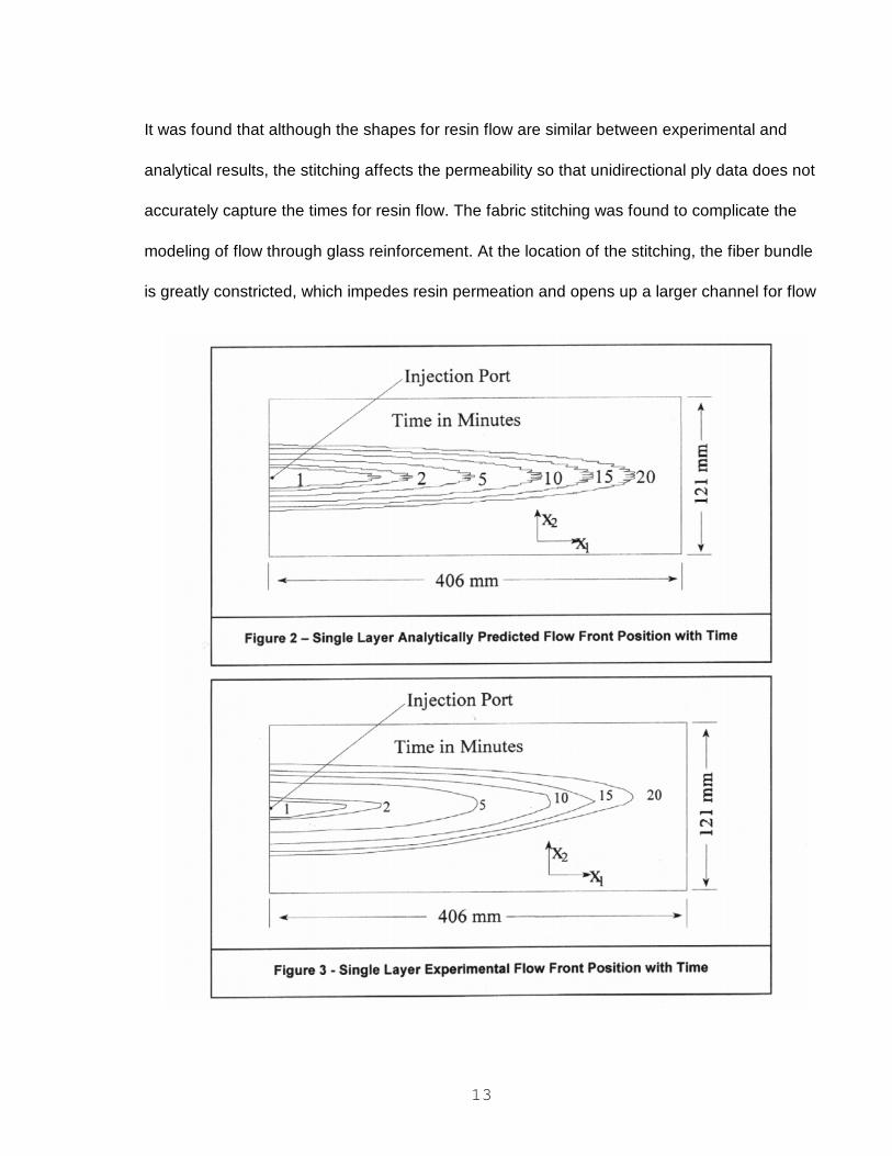
13
It was found that although the shapes for resin flow are similar between experimental and
analytical results, the stitching affects the permeability so that unidirectional ply data does not
accurately capture the times for resin flow. The fabric stitching was found to complicate the
modeling of flow through glass reinforcement. At the location of the stitching, the fiber bundle
is greatly constricted, which impedes resin permeation and opens up a larger channel for flow
14
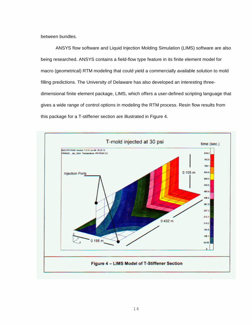
between bundles.
ANSYS flow software and Liquid Injection Molding Simulation (LIMS) software are also
being researched. ANSYS contains a field-flow type feature in its finite element model for
macro (geometrical) RTM modeling that could yield a commercially available solution to mold
filling predictions. The University of Delaware has also developed an interesting three-
dimensional finite element package, LIMS, which offers a user-defined scripting language that
gives a wide range of control options in modeling the RTM process. Resin flow results from
this package for a T-stiffener section are illustrated in Figure 4.

15
ADplications and Technology
The primary motivation
behind the background research and
evaluation of the RTM process is due
to the attention it has received from
its successes in other applications.
As the use of composite materials
continues to grow, the number of
RTM applications grows just as
rapidly, filling niches that cannot be
accommodated effectively by any
other process. For example, in recent developments of the Army�s Commanche helicopter, a
prototype composite keel beam was manufactured, using RTM, that illustrated a few of the
method�s advantages. By substituting this composite assembly for its metal counterpart, the
number of fasteners was reduced from 60,000 to 6,000 and the number of parts making up
the beam structure was reduced from 6,000 to 350 [4]. These part reductions facilitated a
structure of less material and fewer hours of assembly time. Another example is the case of a
commercial jet�s exit, which is a spin-off of a development in the F-22 advanced fighter
project. Initially this 110-inch diameter jet exit was manufactured from titanium alloys and
tipped the scales at 770 pounds. After resin transfer molding the part using carbon fiber
reinforcement, the weight was reduced to 470 pounds and the cost by 38% [5].
These successes in RTM manufacturing are encouraging, but they also raise the
following questions: can RTM technology and its recent advances be applied to wind turbine

16
blades in a cost-effective
manner? Through a
literature review of current
research, four key areas
have been identified that
illustrate the potential
application of RTM
technology to wind turbine
blades: mold advances, core integration, automation and sensor technology. The question of
economics will be answered in the next section.
The first RTM advance that pertains to turbine blade design is mold tooling. Dodge
and Aero Detroit Inc. have made advances in this area, specifically in the development of
resin transfer molded body panels for the Viper automobile. In 1992 when this car was first
introduced, epoxy molds were utilized in the fabrication of 300 cars. In 1993 as demand rose
to 3,000 automobiles, Dodge required RTM molds that increased the rate of production ten-
fold while maintaining tolerances and longevity. The solution was to implement heated nickel
shell molds. By using nickel shell molds at a temperature between 140 — 150 degrees
Fahrenheit, Dodge was able to get panel cycle times down to 5 minutes and make its annual
quota of Vipers [6]. These heated metal molds also allowed Class-A surfaces to be attained
without gel coats, which meant the body panels could be painted right out of the mold. This
type of dimensional control is paramount for the demanding aerodynamic performance of
wind turbine blades and could allow turbine blades to be painted without secondary
resurfacing.
17
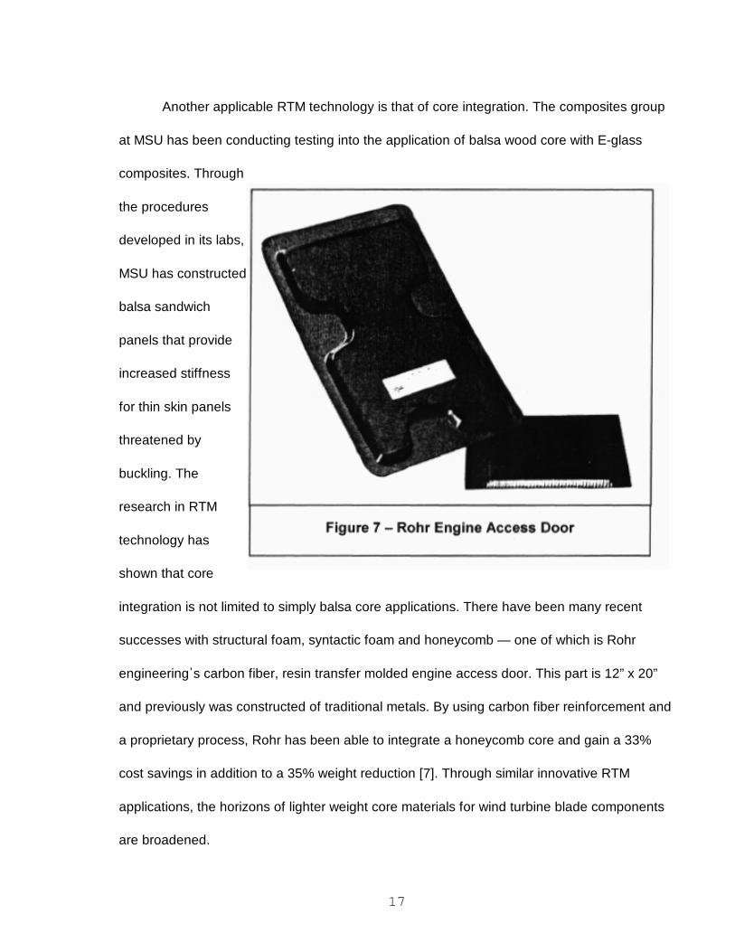
Another applicable RTM technology is that of core integration. The composites group
at MSU has been conducting testing into the application of balsa wood core with E-glass
composites. Through
the procedures
developed in its labs,
MSU has constructed
balsa sandwich
panels that provide
increased stiffness
for thin skin panels
threatened by
buckling. The
research in RTM
technology has
shown that core
integration is not limited to simply balsa core applications. There have been many recent
successes with structural foam, syntactic foam and honeycomb — one of which is Rohr
engineering�s carbon fiber, resin transfer molded engine access door. This part is 12” x 20”
and previously was constructed of traditional metals. By using carbon fiber reinforcement and
a proprietary process, Rohr has been able to integrate a honeycomb core and gain a 33%
cost savings in addition to a 35% weight reduction [7]. Through similar innovative RTM
applications, the horizons of lighter weight core materials for wind turbine blade components
are broadened.

18
Another emerging area of RIM applications in industry is automation. After visualizing
the large potential of RTM in aircraft structures, Boeing subcontracted Radius Engineering to
develop an automated system for resin transfer molding. Boeing required the automation of
RTM�d commercial jet parts up to 74” x 36” x 30” to be performed under computer control [8].
To meet this challenge Radius developed a system of automation that uses “shuttle carts” to
ship the RTM part through different stages of the process. Radius found that to meet
Boeing�s production requirements, heated molds would be necessary. Similar automation
methods could readily be explored for the production of turbine blades.

19
Research was also conducted
in the area of mold filling. Radius
Engineering made another advance in
RTM technology by introducing
sensors to monitor mold fill. This firm
developed new sensors that will
monitor state of cure, flow front,
pressure and temperature throughout
the tooling during resin transfer
molding [9]. Another line of products
offered by this company is a thermoplastic sensor that provides an inexpensive way to
monitor flow positions. Such sensor technology could provide invaluable information into the
nature of resin flow through a long mold, such as larger 25-meter long turbine blades.

20
Economic Evaluation
In the military applications discussed earlier, healthy budgets were allotted to
determine whether it was possible to accomplish certain tasks using the RTM process. Wind
turbine construction poses a different scenario: every effort needs to be focused on
squeezing the most out of the limited time and money available. MSU�s turbine blade work
involves a comparison of RTM against a variety of other processes according to structural
integrity, overall weight and final cost of a production blade. Discovering reliable cost data for
a hand laid-up turbine blade versus one built with the RTM process is difficult. The RTM
method has not been applied to commercial turbine blade construction to allow the
development of good economic figures. The best that can be offered at this time are outlines
of the expected capital and operating requirements for the two methods (see Tables I & 2).
To understand the benefits and limitations of RTM, the initial cost of mold construction
and resin applying equipment was investigated. Due to the open mold nature of the hand lay-
up process, very low pressures are applied to the resin, which allows for the use of light mold
reinforcing and little capital investment. In a brief conversation with Chuck Hedley of
Headwaters Composites, he explained that for the hand lay-up of a wind turbine blade, wood
would be an excellent candidate for mold reinforcement. RTM, however, uses much higher

21
pressures to force the resin through the process, thereby requiring a much stronger mold
reinforcing material, such as steel. For a rough estimate in costs, Hedley suggested that a
polyester, hand lay-up mold for fabricating blades 24� in length would cost approximately
twelve thousand dollars. He estimated that an RTM mold for a similar part would run about
thirty five thousand dollars, almost triple the hand lay-up mold cost, due to the heavier
reinforcement material and the hinging or hoisting mechanisms. Yet with hand lay-up, the
excessive release of volatiles requires that a ventilation system investment be included in the
capital costs. The closed-mold feature of RTM also requires hoisting equipment to open and
close the 24� long steel reinforced mold. Indirect costs of the two processes have yet to be
made available.
When comparing the start up costs of these two turbine blade manufacturing
methods, RTM comes in second place, but when measuring the two according to operating
costs, RTM comes out significantly ahead. Both processes require the hand placement of
reinforcement into the molds, but in the RTM process the manual application of resin is
eliminated, which may double the daily output of blades. Additionally, RTM uses its materials
more effectively. For example, in a 24� turbine blade application the RTM process is 100%
repeatable and results in only two square feet of excess material; in comparison, fabricating

22
the same blade using hand lay-up would result in eight square feet of wasted material [10].
Due to the natural repeatability of the resin transfer molding process, resin transfer molded
turbine blades have higher part consistencies and thus are more reliable in satisfying the
requirement of a 30-year life span.

23
Conclusions
The current research examined the available methods of composites manufacturing and compared
their potential for fabricating blades. Resin transfer molding was found to be a promising option due to its
advantages in delivering large, complex parts with consistent part properties and excellent surface
finishes. One of RTM�s primary challenges, RTM modeling, was addressed and continues to be explored
in MSU�s task to develop and apply mold filling software.
RTM applications and technology were also investigated. A series of examples was found, and a
selected number of these illustrate the weight and cost savings of the process. Some of the key issues in
advancing RTM technology were briefly addressed: tooling, core integration, automation and process
sensing. The initial and operating costs of RTM were also weighed against the costs of hand lay-up and
found to be competitive. This inquiry into RTM has shown that the process may have advantages in
producing blades that are lighter, stronger, more economical and more consistent in properties when
compared to the traditional hand lay-up technique.

24
References
[1] BTM Consult. “International Wind Energy Development,” 1996 World Market Update: 23-25.
[2] Schwartz, Mel M. Composite Materials — Processing. Fabrication, and Applications, Vol. 2. Prentice
Hall PIR, NJ. 1997.
[3] Samborsky, Dan. Private Communication concerning 3M Industrial Specialties Division orders.
October 3, 1997.
[4] Cairns, Douglas S., Humbert, Dell R., and Mandell, John F. “Modeling of Resin Transfer Molding of
Composite Materials with Oriented Unidirectional Plies,” submitted October, 1997 to Composites: PartA
in review.
[5] McConnell, Vicki. “Making New Moves with Composites,” High Performance Composites
Sourcebook 1997, vol. 4(6): 10-25.
[6] Hawkinson, Bill. “RTM: the Next Generation Targets Body Panels,” Plastics Technology. September
1994, vol. 40: 46-48.
[7] Fisher, Karen. “RTM and core materials offer product advances,” High Performance Composites.
September/October 1995, vol. 3(5): 23-26.
[8] Stover, Debbie. “RTM�ing Large Parts,” High Performance Composites. March/April 1995, vol. 3(2):
39-46.
[9] Fisher, Karen. “Resin flow is the key to RTM success,” High Performance Composites.
January/February 1997, vol. 5(1): 34-38.
[10] Hedley, Chuck. President of Headwaters Composites. Private Communication over RTM expansion
possibilities. June 23,1997.


