41
Notre Dame Rocketry Team Preliminary Design Review November 12, 2014 1:30 PM CT
| Date post: | 18-Dec-2015 |
| Category: |
Documents |
| Upload: | clare-mason |
| View: | 216 times |
| Download: | 1 times |

Notre Dame Rocketry Team
Preliminary Design Review
November 12, 2014
1:30 PM CT

Mission Objectives
• Launch rocket to precisely 3,000 feet AGL– Success: +/-50 feet
• Autonomously load payload into rocket• Erect rocket to 5 degrees off-vertical• Autonomously install igniter• Eject payload at 1,000 feet AGL• Successful recovery
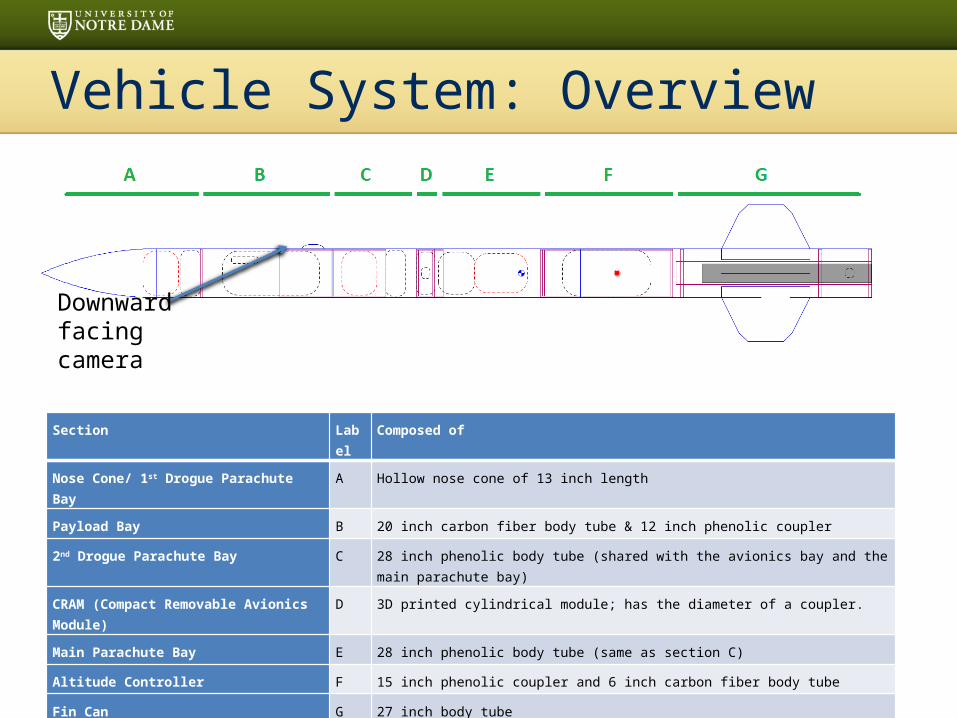
Vehicle System: Overview
Downward facing camera
Section Label Composed of
Nose Cone/ 1st Drogue Parachute Bay A Hollow nose cone of 13 inch length
Payload Bay B 20 inch carbon fiber body tube & 12 inch phenolic coupler
2nd Drogue Parachute Bay C 28 inch phenolic body tube (shared with the avionics bay and the main parachute bay)
CRAM (Compact Removable Avionics Module) D 3D printed cylindrical module; has the diameter of a coupler.
Main Parachute Bay E 28 inch phenolic body tube (same as section C)
Altitude Controller F 15 inch phenolic coupler and 6 inch carbon fiber body tube
Fin Can G 27 inch body tube

Vehicle System - Dimensions
• Three parachutes (two drogues, one main)
• Separates into two sections
• Has an altitude control mechanism
• Structure made of kraft phenolic, with carbon fiber reinforced sections
• Top speed of 490 ft/s• Center of pressure at
altitude controller
Length of Rocket (in) 94Diameter of Rocket (in) 5.54Number of Fins 4Fin Span (in) 15Weight with Motor (oz) 432Weight without Motor (oz) 374Estimated Stability Margin with Motor
1.96
Estimated Stability Margin without Motor
2.79

Vehicle System - Subscale Rocket
• Three different launch configurations:1. Altitude controller
deactivated2. Altitude Controller activated3. Payload bay with door
• Interchangeable sections• 0.4 Scale factor• 2.276in diameter body-
tube• Aerotech G78 Motor• 1250ft Apogee

Vehicle System: Propulsion
• Cesaroni K1200 Motor– Necessary impulse– Subsonic
• Thrust to Weight: 9.9:1
• Rail Exit Velocity: 45 ft/s– Stable flight
Max Thrust (lbs) 308
Avg. Thrust (lbs) 268
Burn Time (s) 1.69
Total Impulse (lbf-s) 452
Loaded Weight (lbs) 3.6
Empty Weight (lbs) 1.43

Simulations and Thrust CurveSource Peak Altitude (ft) Peak Velocity (ft/s)
OpenRocket 3137 489
Structures System: Materials
• Nosecone: polypropylene plastic– High compressive strength
• Airframe/couplers: phenolic and carbon fiber– Standard high power rocket material– Carbon fiber used in areas where extra support is
necessary• Hatched Door• Altitude Control System
• Fins: Aircraft plywood MIL-P-6070– 0.2” thick
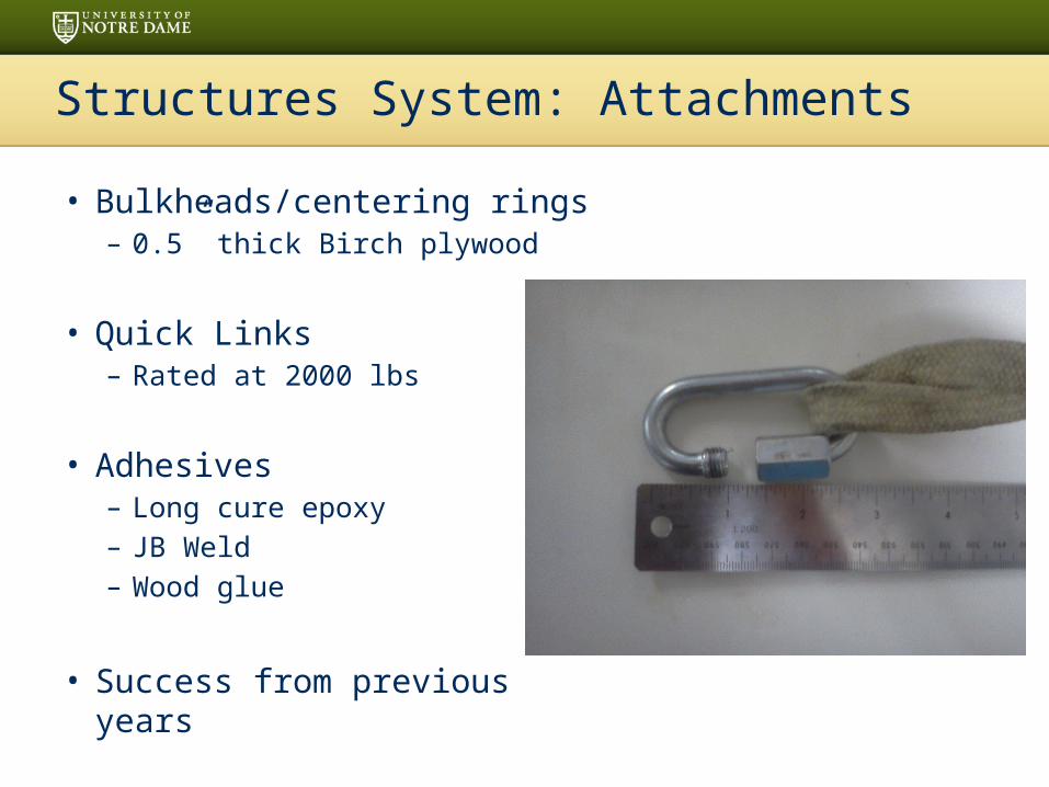
Structures System: Attachments
• Bulkheads/centering rings– 0.5” thick Birch plywood
• Quick Links– Rated at 2000 lbs
• Adhesives– Long cure epoxy– JB Weld– Wood glue
• Success from previous years

Recovery System: Hardware
• Triple Deployment System– 50” elliptical drogue parachute with bleed hole at
apogee– 50” elliptical drogue parachute with bleed hole at
1,000 feet– 96” elliptical main parachute with bleed hole at 650
feet
• Tubular Kevlar recovery harness– 30 feet ~ 3 times length of rocket
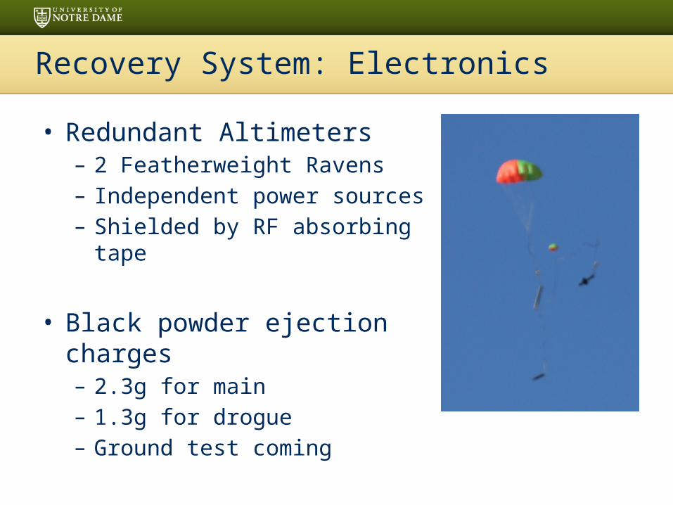
Recovery System: Electronics
• Redundant Altimeters– 2 Featherweight Ravens– Independent power sources– Shielded by RF absorbing tape
• Black powder ejection charges– 2.3g for main– 1.3g for drogue– Ground test coming
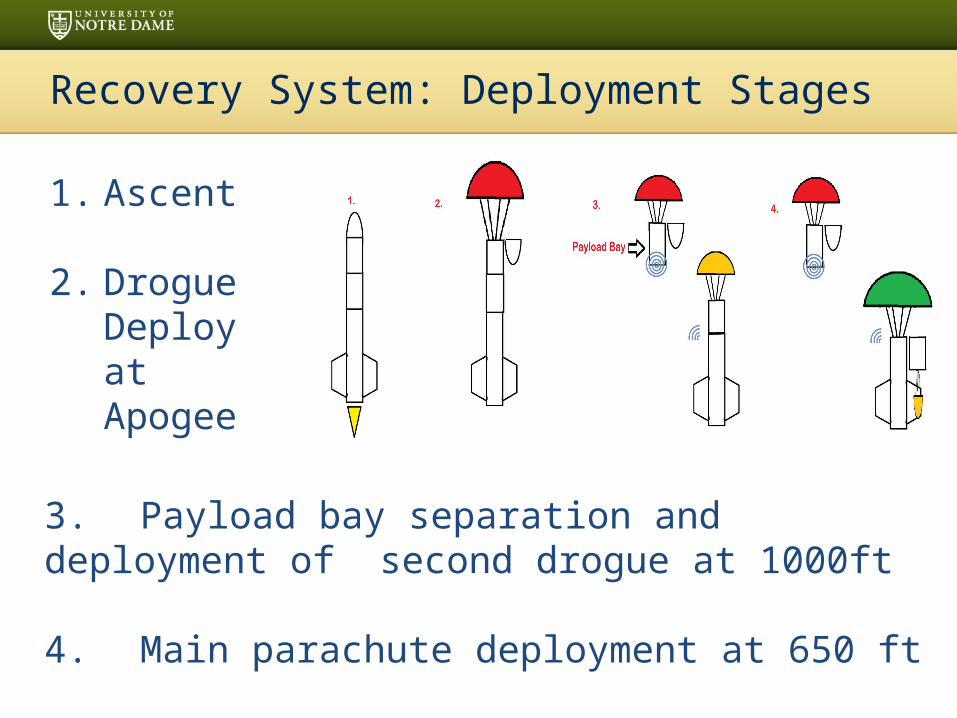
Recovery System: Deployment Stages
1. Ascent
2. Drogue Deploy at Apogee
3. Payload bay separation and deployment of second drogue at 1000ft
4. Main parachute deployment at 650 ft

Recovery System: Descent
• Descent Rates– 36.3 ft/s under drogue
After rocket separates into two untethered sections– 15.2 ft/s under main– 21.5 ft/s under drogue
Section Weight (lbf) Kinetic Energy (ft-lbf) KE Margin
Bottom Section (Main) 17.1 50.7 32.4 %Hazard Bay (Drogue) 5.6 31.4 58.1 %Nose Cone (Drogue) 1.7 2.9 96.1 %
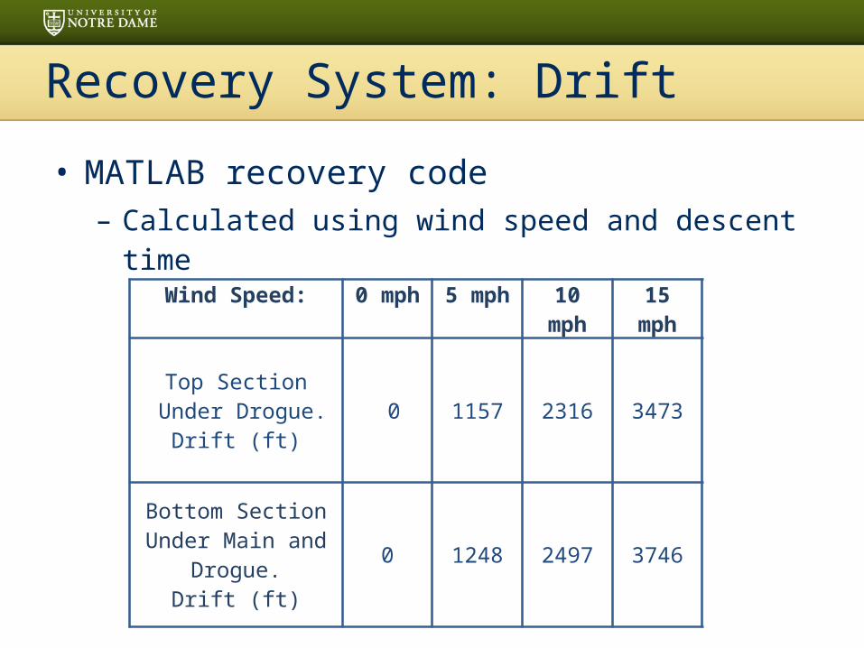
Recovery System: Drift
• MATLAB recovery code– Calculated using wind speed and descent time
Wind Speed: 0 mph 5 mph 10 mph 15 mph
Top Section Under Drogue.
Drift (ft) 0 1157 2316 3473
Bottom SectionUnder Main and
Drogue.Drift (ft)
0 1248 2497 3746

• Innovative concept replaces the traditional avionics bay design
• Altimeters and power supplies contained in 3D-Printed Compartment– Less than two inches in length,
same diameter as a coupler– Dedicated cavities for each
component provide protection and organization
– Provides independent electromagnetic shielding for each altimeter
Recovery System: CRAM
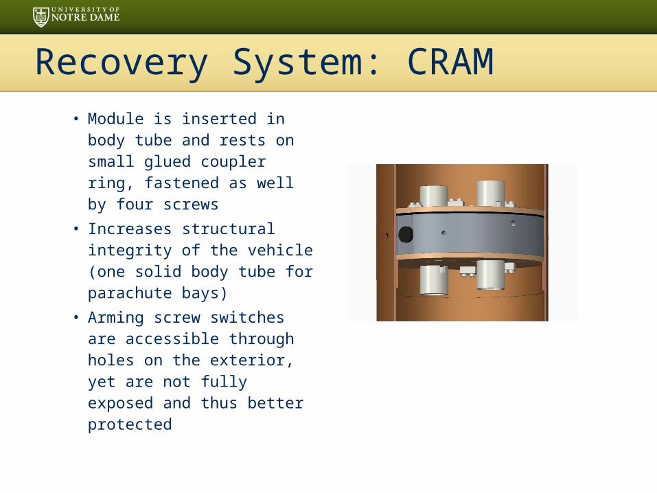
• Module is inserted in body tube and rests on small glued coupler ring, fastened as well by four screws
• Increases structural integrity of the vehicle (one solid body tube for parachute bays)
• Arming screw switches are accessible through holes on the exterior, yet are not fully exposed and thus better protected
Recovery System: CRAM
Altitude Controller Payload
• Purpose: Increase drag– Reduce rocket apogee
• Requirements: fast acting– Minimal stability affects– Must be reusable
• Terms of Success– Apogee ≈ 3,000 feet– No catastrophic failure of rocket

Altitude Controller: Design
• “Skirt” design• Deployed by solenoids • Retracted passively by aerodynamic
forces• Electromagnet locking mechanism• Controlled by Arduino Uno
– Accelerometer and altimeter for measurements
• Battery banks• Support core and structural stringers
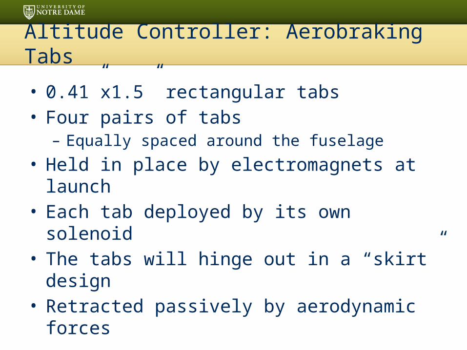
Altitude Controller: Aerobraking Tabs
• 0.41”x1.5” rectangular tabs• Four pairs of tabs
– Equally spaced around the fuselage
• Held in place by electromagnets at launch• Each tab deployed by its own solenoid• The tabs will hinge out in a “skirt” design• Retracted passively by aerodynamic
forces

Altitude Controller: Solenoids
• Eight linear “pull” solenoids • Require 12 V and 8.4 W each• Rechargeable batteries in series• Generate 1.94 lbf at 0.25” stroke
– Sufficient for needed tab design
• Expect high reliability under operating conditions
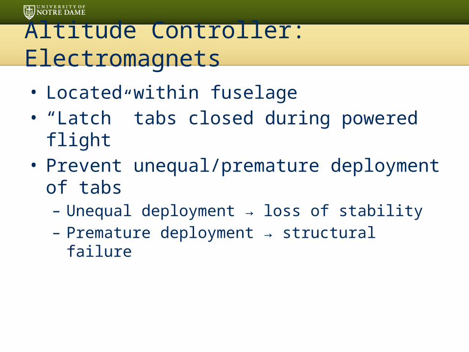
Altitude Controller: Electromagnets
• Located within fuselage• “Latch” tabs closed during powered flight• Prevent unequal/premature deployment of
tabs– Unequal deployment → loss of stability– Premature deployment → structural failure

Electronic Control System
• Built around Arduino Uno• Measure time, altitude
and acceleration• Calculate velocity and
predicted apogee• Deploy tabs to adjust
apogee accordingly
LIS331 Accelerometer
MPL3115A2 Altimeter
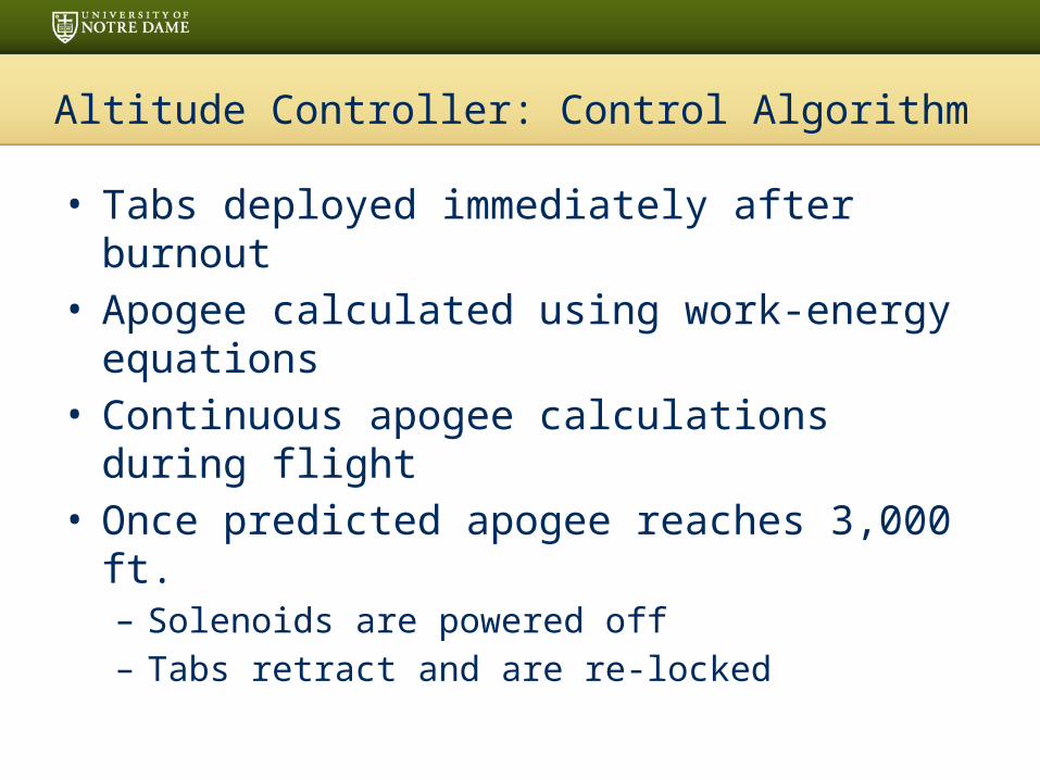
Altitude Controller: Control Algorithm
• Tabs deployed immediately after burnout• Apogee calculated using work-energy
equations• Continuous apogee calculations during
flight• Once predicted apogee reaches 3,000 ft.
– Solenoids are powered off– Tabs retract and are re-locked

Altitude Controller: Power Control System
• Relays controlled by the Arduino to connect and disconnect the solenoids and electromagnets to power
• Additional relay to connect the Arduino to power controlled by main flight computer

Altitude Controller: Structural Support
• Payload design requires changes to fuselage
• Measures to maintain structural stability– Four metal rods acting as stringers– Wooden support structure
• Run the length of tabs

Verification
• Electronics System– Simulations– Flight testing
• Physical Mechanism – Ground Testing– Wind Tunnel– Full Scale Test Flight
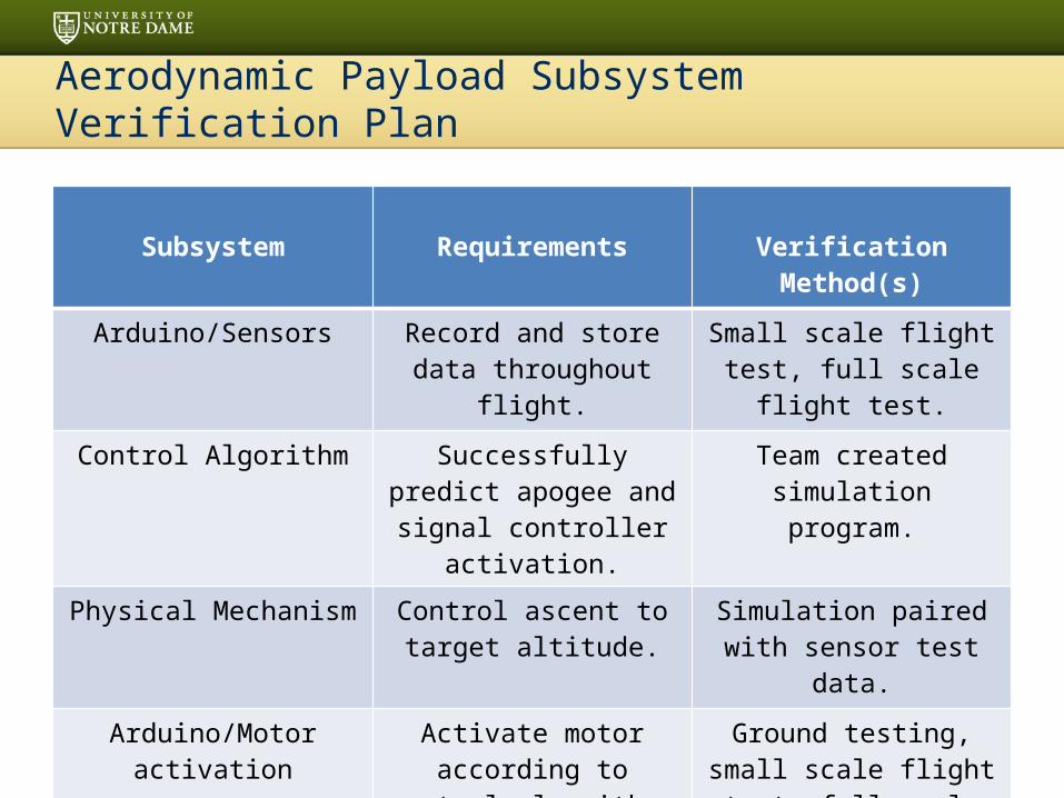
Aerodynamic Payload Subsystem Verification Plan
Subsystem Requirements Verification Method(s)
Arduino/Sensors Record and store data throughout flight.
Small scale flight test, full scale flight test.
Control Algorithm Successfully predict apogee and signal controller
activation.
Team created simulation program.
Physical Mechanism Control ascent to target altitude.
Simulation paired with sensor test data.
Arduino/Motor activation Activate motor according to control algorithm.
Ground testing, small scale flight test, full scale flight
test.

Communications System
Divided into 5 sections1. Primary Control Unit2. Secondary Control Unit3. Radio Frequency Downlink System4. Power Management Systems5. Ground Station

Comm: PCU/SCU
• Responsible for managing all electronic aspects of the rocket
• Capabilities include:– Accept commands from ground station.
Critical for maintain 2 hour battery life while on pad
– Detect separation of rocket– Collect all data/telemetry for transmission
Comm: PCU/SCU Communication
• Two Xbee modules used for short range transmissions (~1000m)
• SCU → PCU → RFDS → Ground Station• Halves of the rocket can communicate
before and after separation• Xbee on ground station can also receive
transmissions from close range if needed• Very efficient control system

Comm: Radio Frequency Downlink
• Link between the rocket and the ground station
• Transmitter is:– Baofeng UV-5r - 145.750 MHz - 4 W
• One student, Benny, has a technician amateur radio license, but looking to expand
• Compliant with amateur radio rules– Station ID is broadcast with each packet sent
• Radio power extensively tested

Comm: Power Management System
• Critical that all electrical systems maintain power for 2+ hours
• NiMH battery pack to be used for the following:– PCU/SCU (arduino)– Altitude controller– Any other systems necessary
• NiMH battery packs rechargeable and allow for higher current

Comm: Ground Station
• LCD Displays:– Display GPS data, sensor information,
voltages, etc.
• Control Panel:– Uses switches to turn on various functions of
the system– LEDs will verify proper functionality of
payload– Robust confirmation system to prevent errors
(or notify user if unavoidable/unfixable)
AGSS: Concept Features & Definition
• Creativity and originality– Subsystems of AGSS– Modular launch pad
• Uniqueness and significance– Technology for Martian environment
• Suitable level of challenge– Team’s first time developing an autonomous
system to launch a rocket

AGSS: Science Value
• Objectives– Fully autonomous
procedures– Payload integration– Rail erection– Igniter installation– Within 10 minutes– Systems must work in a
Martian environment
• Success criteria– Schedule– Quality– Functionality
• Accuracy• Consistency
AGSS: Science Value
• Experimental logic– Minimize points of
error– Simplify systems
• Approach– Compartmentalizatio
n
• Method of investigation– Separated tasks– Developed systems
• Test and measurement– Structural– Capability
• Variables– Consistency and
accuracy– Environment
• Controls– System specifications– Functionality and
objective– Order of operation
AGSS: Science Value
• Relevance of expected data– Will determine
consistency of system
• Accuracy/error analysis– Programming
motor movement– Error in physical
build
• Preliminary experiment process procedures– Finalize designs– CAD Models– Component
selection– Prototyping– Testing and tuning

Requirements Verification
• Recovery – Commercially available altimeter– 2 untethered sections, each under 75 ft-lbs. at landing
• Launch Vehicle– 2 hour preparation time– Can sit on pad for 2 hours– Full scale and subscale test will be completed– Checklists used
• AGSS– Completely autonomous– Pause Switch
Testing Plan: Recovery
• Ground testing– Altimeters– Black powder– Electrical Interference

Testing Plan: Vehicle
• 3 Subscale flights planned
• Two full scale test flights planned1. January 17 flying qualities, controller,
communications
2. February 14 AGSS, Contest Rehearsal

Questions?


