40
Nova-243 Outdoor 2x10W FDD/TDD eNodeB Installation Guide August 2018 Version 1.5

Nova-243 Outdoor 2x10W
FDD/TDD eNodeB Installation Guide
August 2018
Version 1.5
2
About This Document This document is intended for personnel who will be installing the Baicells Nova-243 Outdoor 2x10W eNodeB (eNB) based on Frequency Division Duplexing (FDD) and Time Division Duplexing (TDD) Long-Term Evolution (LTE) technology. Proper installation, power, and grounding are necessary for normal operation of the eNB. Please be advised that only personnel with the appropriate electrical skills and experience should install this device.
Copyright Notice Baicells Technologies, Inc., copyrights the information in this document. No part of this document may be reproduced in any form or means without the prior written consent of Baicells Technologies, Inc. The Baicells logo is a proprietary trademark of Baicells Technologies, Inc. Other trademarks mentioned in this document belong to their owners.
Disclaimer All products, services, and features bought from Baicells Technologies, Inc., are subject to the constraints of the company's business contract and terms. All or part of the products, services, or features described in this document might not be your specific Baicells network. Unless stated in the contract, Baicells Technologies, Inc., does not make any explicit or default statement or guarantee about the contents of this document.
Unless stated otherwise, this document serves only as a user guide, and all descriptions/information/suggestions mean no guarantee, neither explicit nor implicit.
The information in this document is subject to change at any time without notice. For more information, please consult with a Baicells technical engineer or the support team. Refer to the “Contact Us” section.

3
Revision Record Date Version Description SMEs/Contributors Writer/Editor
31-Aug-2018 V1.5 Updated GUIs NA Sharon Redfoot
13-Mar-2018 V1.4 Updated specs Yang Yanan Sharon Redfoot
18-Jan-2018 V1.3 Updated technical specs; SME review for publication
Cameron Kilton Rick Harnish
Sharon Redfoot
15-Jan-2018 V1.2 Incorporated SME comments
Cameron Kilton Sharon Redfoot
10-Jan-2018 V1.1 Draft English version based on Nova 10W
Yang Yanan Sharon Redfoot
8-Jan-2018 V1.0 Initial Chinese version IG Yang Yanan
Related Documents Other Baicells technical documents may be found on the Baicells support website. The website information is provided below under “Contact Us”.
UE – Gen 1 Atom 5dBi Indoor CPE User Manual Atom 11dBi Outdoor CPE User Manual Atom 19.5dBi Outdoor CPE User Manual UE – Gen 2 Atom ID04/06-6.5 User Manual Atom OD04/06-14/19.5 User Manual eNB – Gen 1 Nova 1W Base Station Installation Guide Nova 1W Quick Start Guide Nova 10W Base Station Installation Guide Nova 10W Quick Start Guide eNB – Gen 2 Nova-227 Outdoor 2x250mW TDD eNB Installation Guide Nova-227 Quick Start Guide Nova-233 Outdoor 2x1WG2 FDD-TDD eNB Installation Guide Nova-233 Quick Start Guide Nova-243 Outdoor 2x10W FDD-TDD eNB Installation Guide (this
document) Nova-243 Quick Start Guide Nova-436 Outdoor 4x1W CCA TDD eNB Installation Guide Nova-436 Quick Start Guide Nova-446 Outdoor 4x10W FDD eNB Installation Guide (forthcoming) Nova-446 Quick Start Guide (forthcoming) elfcell-220 Indoor 2x50mW FDD eNB Installation Guide (forthcoming) elfcell-220 Quick Start Guide (forthcoming) NeutralCell Indoor Multi FDD-TDD Small Cell Installation Guide
(forthcoming)

4
NeutralCell Quick Start Guide (forthcoming) Neutrino-224 Indoor 2x125mW FDD-TDD eNB Installation Guide
(forthcoming) Neutrino-224 Quick Start Guide (forthcoming) SolarCell Outdoor Solution Installation Guide (forthcoming) SolarCell Quick Start Guide (forthcoming) Spectra LTE-U Outdoor 2x500mW FDD eNB Installation Guide
(forthcoming) Spectra LTE-U Quick Start Guide (forthcoming) System, CloudCore, OAM Baicells Configuration & Network Administration Guide Baicells Handoff Configuration Guidelines (Beta trial) Baicells HaloB User Guide Baicells BOSS API Manual Baicells Operation, Maintenance, & Troubleshooting Guide
(forthcoming) Baicells Enterprise EPC Deployment Guide (forthcoming) Baicells Enterprise EPC User Guide (forthcoming)
Contact Us
Baicells Technologies Co., Ltd. Baicells Technologies North America, Inc.
China North America
Address 3F, Bldg. A, No. 1 Kai Tuo Rd, Haidian Dist, Beijing, China
555 Republic Dr., #200, Plano, TX 75074, USA
Phone +86-10-62607100 +1-888-502-5585
Email [email protected] [email protected] or [email protected]
Website www.Baicells.com https://na.Baicells.com
5
Safety Information For the safety of installation personnel and for the protection of the equipment from damage, please read all safety warnings. If you have any questions concerning the warnings, before installing or powering on the base station contact the Baicells support team.
Warning IMPORTANT SAFETY INSTRUCTIONS
This warning symbol means danger. You are in a situation that could cause bodily injury. Before you work on any equipment, be aware of the hazards involved with electrical circuitry and be familiar with standard practices for preventing accidents.
Warning Read the installation instructions before you connect the system to its power
source.
Warning Installation of the equipment must comply with local and national electrical
codes.
Warning This product relies on the existing building or structure for short-circuit
(overcurrent) protection. Ensure that the protective device is rated no greater than 20A.
Warning Do not operate this wireless network device near unshielded blasting caps or
in an explosive environment unless the device has been modified and qualified for such use.
Warning In order to comply with the United States Federal Communications
Commission (FCC) radio frequency (RF) exposure limits, antennas should be located at a minimum of 20 centimeters (7.9 inches) or more from the body of all persons.

6
Table of Contents 1 Overview ........................................................................................................................ 9
1.1 Introduction ................................................................................................................. 9 1.2 Features ..................................................................................................................... 10
2 Out-of-Box Audit ............................................................................................................ 12 3 Preparation .................................................................................................................... 14
3.1 Personnel ................................................................................................................... 14 3.2 Operator Network Design Plan .................................................................................. 14 3.3 Materials and Tools .................................................................................................... 14 3.4 Computer and Software ............................................................................................ 15 3.5 Interfaces ................................................................................................................... 15 3.6 Location and Environment ......................................................................................... 17 3.7 Spacing ....................................................................................................................... 17 3.8 Power ......................................................................................................................... 17 3.9 Grounding and Lightning Protection ......................................................................... 18 3.10 Weatherproofing ..................................................................................................... 18
4 Installation ..................................................................................................................... 20 4.1 Process Overview ...................................................................................................... 20 4.2 Attach Mounting Bracket or Hooks to eNB ................................................................ 20
4.2.1 Bracket for Pole Mount .................................................................................... 21 4.2.2 Hooks for Wall Mount...................................................................................... 21
4.3 Optional: Attach GPS Antenna to eNB ....................................................................... 22 4.4 Install eNB on Pole or Wall ........................................................................................ 24
4.4.1 Pole Mount ...................................................................................................... 24 4.4.2 Wall Mount ...................................................................................................... 25
4.5 Connect RF Antenna Cables ....................................................................................... 26 4.6 Connect Ethernet Cable ............................................................................................. 26 4.7 Connect Power Connector ......................................................................................... 27 4.8 Connect Grounding Cable .......................................................................................... 27 4.9 Power on the eNB to Check LEDs .............................................................................. 28 4.10 Install Equipment at Final Location ......................................................................... 28
4.10.1 GPS Positioning Considerations ..................................................................... 29 4.10.2 Grounding Protection .................................................................................... 29 4.10.3 Install eNB and RF Antenna ........................................................................... 30 4.10.4 Check eNB Status in Software ....................................................................... 32 4.10.5 Verify Lightning and Grounding Protection ................................................... 34 4.10.6 Weatherproof all Connections ...................................................................... 34
Appendix A: Technical Specifications ................................................................................. 35 Hardware Specifications .................................................................................................. 35 Software Specifications ................................................................................................... 35 Environmental Specifications .......................................................................................... 37 Global Part Numbers ....................................................................................................... 37

7
Appendix B: Regulatory Compliance ................................................................................. 38 FCC Compliance ........................................................................................................ 38 IC Compliance ........................................................................................................... 39
Appendix C: FAQs .............................................................................................................. 40
List of Figures Figure 1-1: Baicells System Architecture ................................................................................. 10 Figure 1-2: Nova-243 eNB ........................................................................................................ 11 Figure 3-1: eNB Interfaces ....................................................................................................... 16 Figure 3-2: Spacing Requirements ........................................................................................... 17 Figure 3-3: Grounding and Lightning Protection ..................................................................... 18 Figure 3-4: Weatherproofing ................................................................................................... 19 Figure 4-1: High-Level Installation Process .............................................................................. 20 Figure 4-2: Pole Mounting Bracket .......................................................................................... 21 Figure 4-3: Wall Mounting Hooks ............................................................................................ 21 Figure 4-4: GPS Mounting Bracket 2 ........................................................................................ 22 Figure 4-5: GPS Mounting Bracket 1 ........................................................................................ 22 Figure 4-6: GPS Antenna .......................................................................................................... 23 Figure 4-7: Completed GPS Antenna Atop eNB ....................................................................... 23 Figure 4-8: Connect GPS Antenna to eNB Port ........................................................................ 23 Figure 4-9: Install Mounting Bracket on Pole .......................................................................... 24 Figure 4-10: Completed Pole Mount ....................................................................................... 25 Figure 4-11: Wall Mount .......................................................................................................... 25 Figure 4-12: RF Antenna Connectors ....................................................................................... 26 Figure 4-13: Connect Ethernet Cable ...................................................................................... 26 Figure 4-14: Connect Power Cable .......................................................................................... 27 Figure 4-15: Connect Power Adaptor to Grounding ................................................................ 27 Figure 4-16: LEDs ..................................................................................................................... 28 Figure 4-17: Grounding Protection .......................................................................................... 29 Figure 4-18: Assemble Directional Antenna ............................................................................ 31 Figure 4-19: eNB Status in GUI ................................................................................................ 32 Figure 4-20: CloudCore Login Page .......................................................................................... 33 Figure 4-21: eNB Status in OMC .............................................................................................. 33 Figure 4-22: Weatherproofing Example .................................................................................. 34

8
List of Tables Table 2-1: Shipping List ............................................................................................................ 12 Table 3-1: Materials ................................................................................................................. 14 Table 3-2: Operator-Supplied Tools ......................................................................................... 15 Table 3-3: eNB Interfaces ......................................................................................................... 16 Table 4-1: LED Descriptions ..................................................................................................... 28
9
1 Overview
1.1 Introduction
The Baicells Nova-243 eNodeB (eNB) is a high-performing outdoor micro base station based on Frequency Division Duplexing (FDD) and Time-Division Duplexing (TDD) Long-Term Evolution (LTE) technology. The Nova eNB enables wired and wireless access to 3G LTE backbone networks. Each eNB supports high-speed broadband data and voice services, helping telecom operators, broadband operators, and enterprises to serve customers in locations that might otherwise be difficult to reach.
The eNB is part of a typical cell site installation of three main entities:
• Baicells eNB unit with integrated Global Positioning System (GPS)
• Optional Global Positioning System (GPS) antenna – furnished by the operator
• Radio Frequency (RF) antenna – furnished by the operator, one per Nova-243 eNB
Each eNB comes pre-configured so that installation is simplified and connection to the core network is plug-and-play. The software applications to configure and manage the Baicells components include a local and Web-based eNB Graphical User Interface (GUI), a local and Web-based user equipment (UE) GUI, and localized or centralized CloudCore applications.
CloudCore is a Software-as-a-Service (SaaS) solution managed and hosted by Baicells via Azure, a Microsoft based and North American hosted Cloud computing platform. CloudCore includes the Operations Management Console (OMC), Business Operations Support System (BOSS), and the forthcoming Evolved Packet Core (EPC). Figure 1-1 illustrates a Baicells system architecture.
For more information about the software applications, please refer to the Baicells Configuration and Network Administration Guide located on the support website as listed under “Contact Us”.

10
Figure 1-1: Baicells System Architecture
1.2 Features
The Nova-243 eNB is lightweight and easy to deploy (Figure 1-2). It offers excellent performance, helping operators to provide better coverage and higher capacity with minimal effort. Following is a list of the key features of the Nova-243. The full technical specifications are provided in Appendix A.
Supports standard LTE FDD bands 1/3/7 and TDD bands 38/40/41/42/48 and customized
Slim design suitable for private and public deployments; uses any IP-based backhaul, including public transmission
Higher transmission power for extended and/or more obstructed coverage; excellent non-line-of-sight (NLOS) performance
Lower power consumption to reduce OPEX
Plug-and-play with self-organizing network (SON) capabilities
Supports Internet of Things (IoT) with most evolved packet core (EPC) vendors

11
Up to 150 Mbps downlink (DL) and 50 Mbps uplink (UL) in FDD mode; up to 112 Mbps DL and 20 Mbps UL in TDD mode
Handles a maximum of 255 (FDD) and 96 (TDD) concurrent users
Local and Web GUI management, and network management using Baicells Operations Management Console (OMC)
Supports emergency gateway (eGW) option for S1 aggregation to reduce signaling load of the Mobility Management Entity (MME)
Supports local traffic offload and charging with eGW, and with both integrated local gateway and external eGW
Highly secured with equipment certification against potential intrusion risk
Figure 1-2: Nova-243 eNB

12
2 Out-of-Box Audit Before opening the box, check to see if the outer packaging is damaged or wet. If it is, or if any items inside are missing or damaged, report the issue to the supplier within 10 days. Table 2-1 is a shipping list showing the quantity of each item you should receive.
Table 2-1: Shipping List
Item Qty Description Photograph of Item Nova-243 eNB 1 This is a Nova-243
eNodeB (eNB). Check the tag on the unit to ensure you received the correct model base station.
Power Supply 1 100V to 277V AC to -48V DC adaptor
Pole Mounting Bracket 2 Fixed accessories
Omega 4 Fixed accessories
Wall Mounting Bracket 3 Fixed accessories
- Upper side of eNB
- Lower side of eNB
M10 outer hex bolt 4

13
M10 nuts, ball pats, and flat gaskets
9
M6*16 inner hex screw kit
11
M10 extension bolt 3
OT Terminal 1
Hydraulic Terminal 1
Waterproof Daub 2
Ultraviolet-proof Tape 1
Ultraviolet-proof Tie 1
Factory Inspection List - Certification 1 User Guide 1 Shipping List 1

14
3 Preparation
3.1 Personnel
Installing the eNodeB (eNB) on a tower, building, or other structure may require at least two people or a tower crew. Installation personnel should be familiar with and follow standard safety precautions concerning height, electricity, and other regulations. Baicells recommends that installation personnel review this entire installation guide before installing.
3.2 Operator Network Design Plan
Installers should refer to the operator’s network design plan for information about specific network components, IP addressing, radio frequency (RF) coverage goals for the specific cell site, and initial configuration settings as required for the installer.
Each cell site may be unique in terms of the type and number of components to install, the coverage area, the user requirements, and so forth. Clearly identify the structure on which the eNB equipment will be installed, the intended height where the antenna and eNB will be attached, the degree of antenna down tilt, and other necessary specifications that may impact the success of the installation.
3.3 Materials and Tools
Tables 3-1 and 3-2 describe the materials and tools you will need during installation. The materials may be purchased through Baicells or an authorized supplier.*
Table 3-1: Materials
Item Description Power Cable Gauge: Less than AWG16 (e.g., AWG14)
Length: Shorter than 1150 feet (350.5 meters) Ethernet Cable Outdoor CAT6 cable
Shorter than 330 feet (100.6 meters) RF Antenna Feeder Cable
50 ohm
RF Antenna Omnidirectional or Directional antenna Maximum 1 antenna per Nova-243 eNB
Ground Wire 16mm² diameter yellow-green wire GPS Antenna GPS antenna with N-type cable and GPS mounting bracket
*NOTE: Baicells does not manufacture antenna components; please refer to the list of distributors on the Baicells website: https://na.Baicells.com/where-to-buy/. Make sure to match the frequency range of the antenna with the eNB, and consult the regulatory rules for your location concerning output power.
15
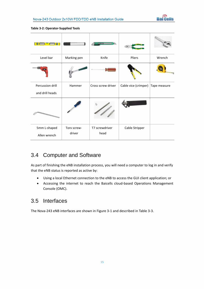
Table 3-2: Operator-Supplied Tools
Level bar Marking pen Knife Pliers Wrench
Percussion drill
and drill heads
Hammer Cross screw driver Cable vice (crimper) Tape measure
5mm L-shaped
Allen wrench
Torx screw-driver
T7 screwdriver head
Cable Stripper
3.4 Computer and Software
As part of finishing the eNB installation process, you will need a computer to log in and verify that the eNB status is reported as active by:
• Using a local Ethernet connection to the eNB to access the GUI client application; or • Accessing the internet to reach the Baicells cloud-based Operations Management
Console (OMC).
3.5 Interfaces
The Nova-243 eNB interfaces are shown in Figure 3-1 and described in Table 3-3.
16
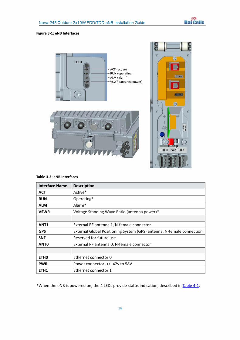
Figure 3-1: eNB Interfaces
Table 3-3: eNB Interfaces
Interface Name Description ACT Active* RUN Operating* ALM Alarm* VSWR Voltage Standing Wave Ratio (antenna power)* ANT1 External RF antenna 1, N-female connector GPS External Global Positioning System (GPS) antenna, N-female connection SNF Reserved for future use ANT0 External RF antenna 0, N-female connector ETH0 Ethernet connector 0 PWR Power connector: +/- 42v to 58V ETH1 Ethernet connector 1
*When the eNB is powered on, the 4 LEDs provide status indication, described in Table 4-1.
17
3.6 Location and Environment
When determining where to place the eNB, you need to consider factors such as climate, hydrology, geology, the possibility of earthquakes, reliable electric power, and transportation access. Refer to the technical specifications in Appendix A: Specifications.
Avoid locating the eNB in areas where there may be extreme temperatures, harmful gases, unstable voltages, volatile vibrations, loud noises, flames, explosives, or electromagnetic interference (e.g., large radar stations, transformer substations). Avoid areas that are prone to impounded water, soaking, leakage, or condensation.
3.7 Spacing
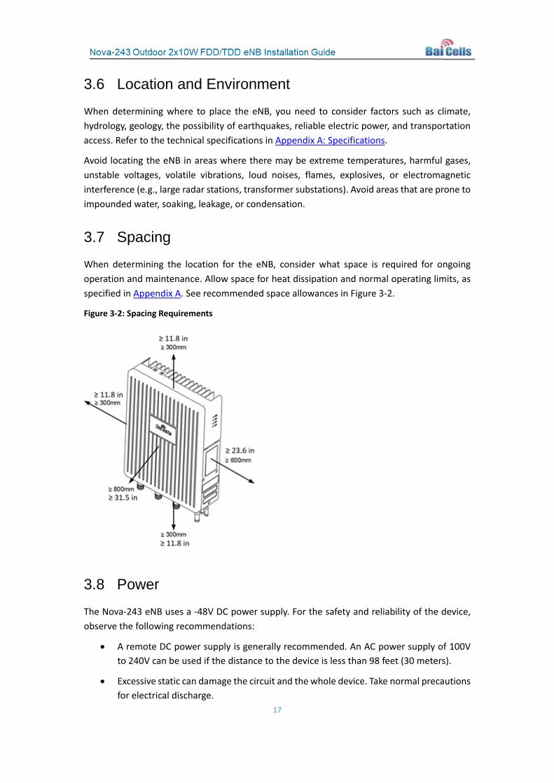
When determining the location for the eNB, consider what space is required for ongoing operation and maintenance. Allow space for heat dissipation and normal operating limits, as specified in Appendix A. See recommended space allowances in Figure 3-2.
Figure 3-2: Spacing Requirements
3.8 Power
The Nova-243 eNB uses a -48V DC power supply. For the safety and reliability of the device, observe the following recommendations:
• A remote DC power supply is generally recommended. An AC power supply of 100V to 240V can be used if the distance to the device is less than 98 feet (30 meters).
• Excessive static can damage the circuit and the whole device. Take normal precautions for electrical discharge.

18
3.9 Grounding and Lightning Protection
The eNB is equipped with a built-in lightning protection unit and an outer ground (GND) terminal for grounding. When installing the eNB, you need to connect the GND port to the ground system with a yellow-green wire. The wire must be inserted in the GND port and fastened with an M6 screw, and then welded with an anti-corrosive process. The wire should be no smaller than 16mm2, as short as possible, and without coiling. Refer to Figure 3-3.
Figure 3-3: Grounding and Lightning Protection
3.10 Weatherproofing
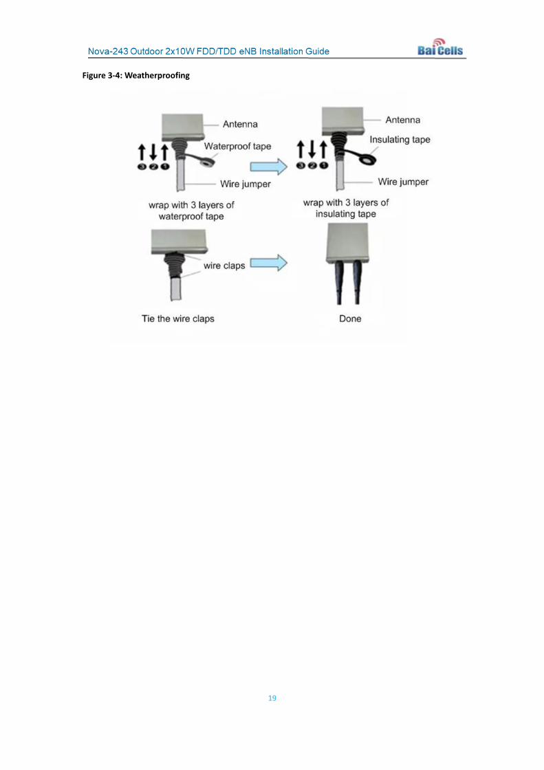
Wrap all connections to protect them with waterproof tape and waterproof daub, as shown in Figure 3-4). At least 3 layers of tape are needed. Make sure the wrapping direction of the last layer of tape is from the bottom up. The last layer should be suitably tight to keep it from cracking. An example is provided in Figure 4-22 later in this document.
19
Figure 3-4: Weatherproofing
20
4 Installation Follow the guidelines and procedures in this section to prepare and install the cell site equipment.
4.1 Process Overview
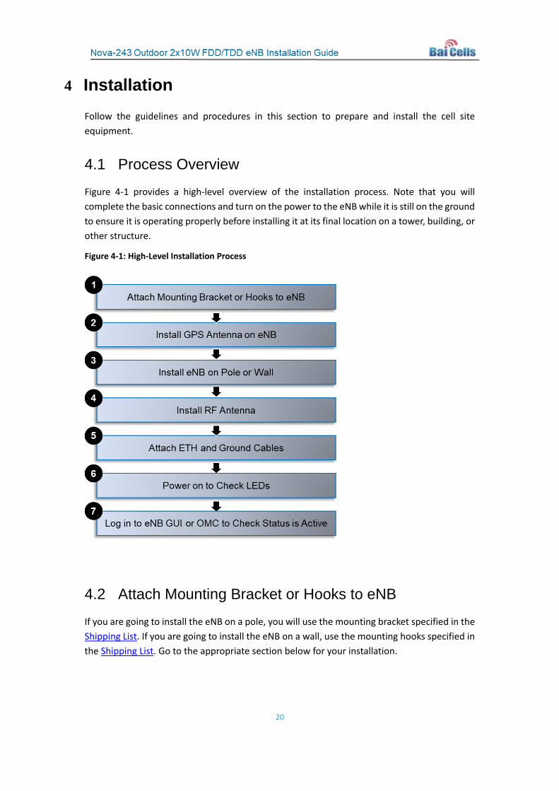
Figure 4-1 provides a high-level overview of the installation process. Note that you will complete the basic connections and turn on the power to the eNB while it is still on the ground to ensure it is operating properly before installing it at its final location on a tower, building, or other structure.
Figure 4-1: High-Level Installation Process
4.2 Attach Mounting Bracket or Hooks to eNB
If you are going to install the eNB on a pole, you will use the mounting bracket specified in the Shipping List. If you are going to install the eNB on a wall, use the mounting hooks specified in the Shipping List. Go to the appropriate section below for your installation.

21
4.2.1 Bracket for Pole Mount
Fix one of the mounting brackets on the eNB using M6*16 screws, as shown in Figure 4-2.
Figure 4-2: Pole Mounting Bracket
Continue to section 4.3 or section 4.4, as appropriate for your installation requirements.
4.2.2 Hooks for Wall Mount
Fix the 3 mounting hooks on the ends of the eNB unit using M6*16 screws (Figure 4-3).
Figure 4-3: Wall Mounting Hooks
Continue to section 4.3 or section 4.4, as appropriate for your installation requirements.
22
4.3 Optional: Attach GPS Antenna to eNB
If you are going to install an optional GPS antenna, you will need to install a GPS antenna lightning arrestor before connecting the optional GPS antenna to the eNB. If more than one antenna will be installed at the same location, separate the antennas by 2.2 yards (2 meters).
Follow the steps below to attach a GPS antenna to the eNB.
1. Prepare the necessary components: GPS antenna, feed cable, GPS mounting bracket 1, and GPS mounting bracket 2.
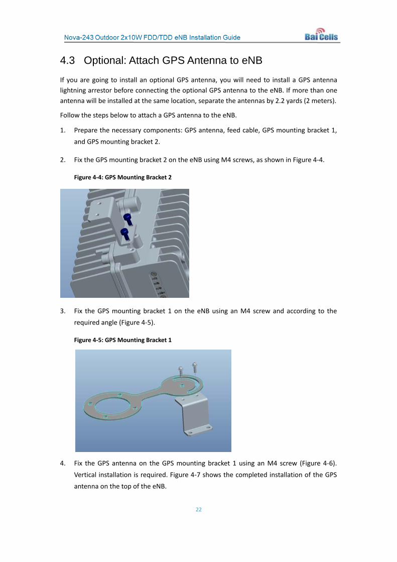
2. Fix the GPS mounting bracket 2 on the eNB using M4 screws, as shown in Figure 4-4.
Figure 4-4: GPS Mounting Bracket 2
3. Fix the GPS mounting bracket 1 on the eNB using an M4 screw and according to the required angle (Figure 4-5).
Figure 4-5: GPS Mounting Bracket 1
4. Fix the GPS antenna on the GPS mounting bracket 1 using an M4 screw (Figure 4-6). Vertical installation is required. Figure 4-7 shows the completed installation of the GPS antenna on the top of the eNB.

23
Figure 4-6: GPS Antenna
Figure 4-7: Completed GPS Antenna Atop eNB
5. Connect the GPS connector cable to the eNB GPS port, as shown in Figure 4-8.
Figure 4-8: Connect GPS Antenna to eNB Port
24
6. After testing eNB operation later in the installation process, you will weatherproof the GPS and antenna connectors using waterproof daub and waterproof tape. Guidelines for installing the GPS at the final location are provided in section 4.6.1. Information on weatherproofing is provided in section 3.10.
4.4 Install eNB on Pole or Wall
Go to the appropriate section, pole mount or wall mount, for your specific installation.
4.4.1 Pole Mount
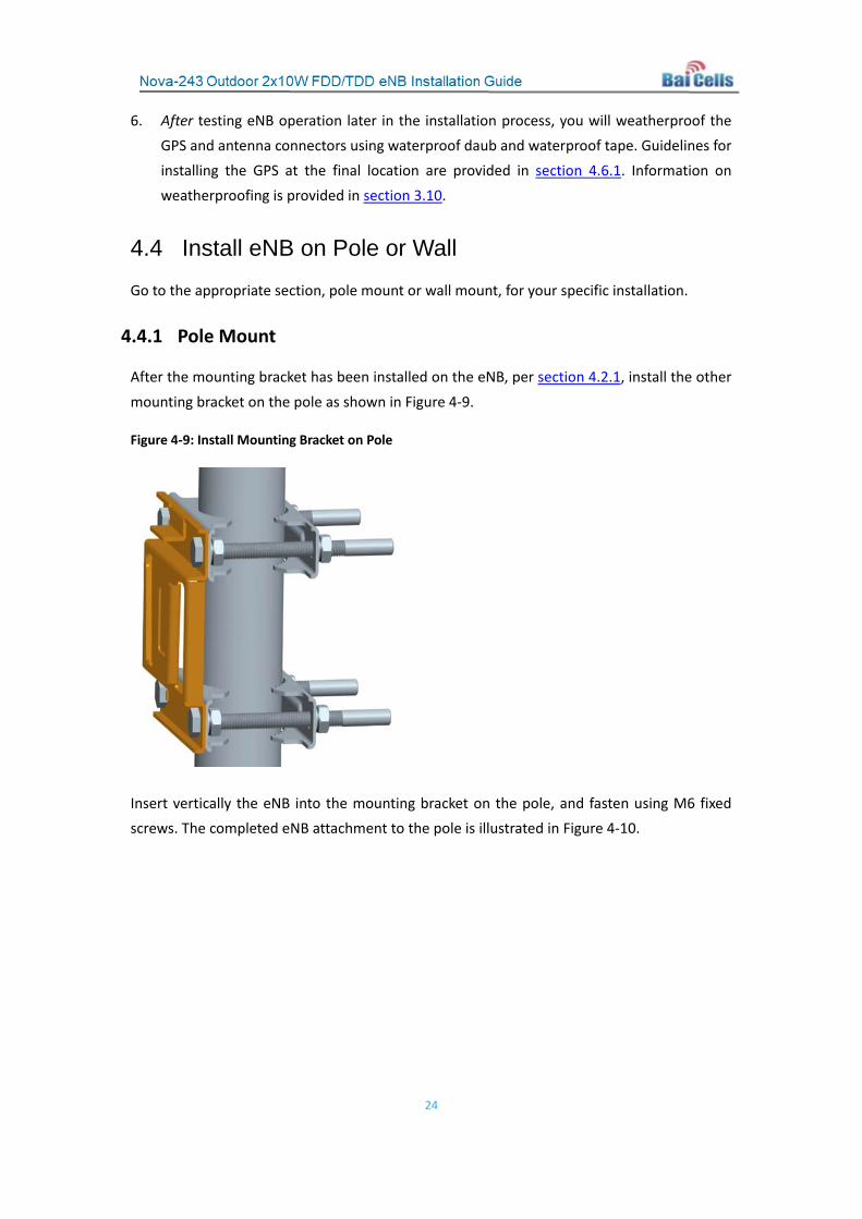
After the mounting bracket has been installed on the eNB, per section 4.2.1, install the other mounting bracket on the pole as shown in Figure 4-9.
Figure 4-9: Install Mounting Bracket on Pole
Insert vertically the eNB into the mounting bracket on the pole, and fasten using M6 fixed screws. The completed eNB attachment to the pole is illustrated in Figure 4-10.
25
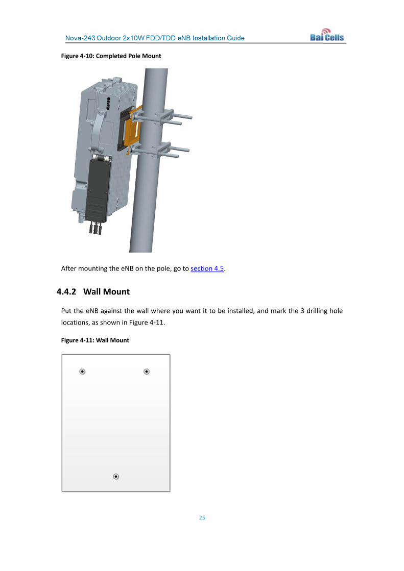
Figure 4-10: Completed Pole Mount
After mounting the eNB on the pole, go to section 4.5.
4.4.2 Wall Mount
Put the eNB against the wall where you want it to be installed, and mark the 3 drilling hole locations, as shown in Figure 4-11.
Figure 4-11: Wall Mount

26
Drill three ½-inch/12-mm diameter sized holes on the wall where marked. Fix the eNB unit on the wall using the M10*80 expansion screws. Continue on to section section 4.5.
4.5 Connect RF Antenna Cables
You will need to prepare the RF cables that run between the eNB and the RF antenna. Follow the steps below to connect the RF antenna cables to the eNB.
1. Connect an RF antenna cable to ANT0 interface on the eNB (Figure 4-12).
2. Connect an RF antenna cable to ANT1 interface on the eNB (Figure 4-12).
3. After testing eNB operation later in the installation process, waterproof the antenna connectors using waterproof daub and waterproof tape. Information on waterproofing is provided in section 4.3.8.
Figure 4-12: RF Antenna Connectors
4.6 Connect Ethernet Cable
Connect the Ethernet cable to the ETH0 interface on the eNB (Figure 4-13), and fasten the screw. The blue cable in Figure 4-14 shows the Ethernet cable connected.
Figure 4-13: Connect Ethernet Cable
27
4.7 Connect Power Connector
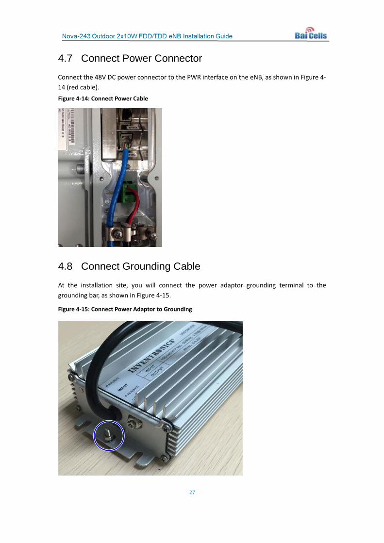
Connect the 48V DC power connector to the PWR interface on the eNB, as shown in Figure 4-14 (red cable). Figure 4-14: Connect Power Cable
4.8 Connect Grounding Cable
At the installation site, you will connect the power adaptor grounding terminal to the grounding bar, as shown in Figure 4-15.
Figure 4-15: Connect Power Adaptor to Grounding

28
4.9 Power on the eNB to Check LEDs
With all components installed and connected locally, power on the eNB unit by plugging the power cord into the electrical socket. With power applied, the LEDs should illuminate as shown in Figure 4-16 and described in Table 4-1.
Figure 4-16: LEDs
Table 4-1: LED Descriptions
Identity Color Status Description
ACT Green Steady On The transmitting channel works
normally
OFF The transmitting channel is not working
RUN Green
Fast flash: 0.125s on, 0.125s off The board is loading.
Slow flash: 1s on,1s off The board is normal. OFF No power input or faulty board
ALM Red Steady On Hardware alarm, e.g., VSWR alarm OFF No alarm
VSWR Red OFF The standing wave is normal.
Steady On The standing wave is larger than normal.
4.10 Install Equipment at Final Location
Installing the eNB should be performed only by qualified installation technicians following the operator’s network design plan and according to industry standard safety precautions. Installation on a wall, roof, tower, or other structure may require a tower crew. Follow standard safety precautions for working at the expected height and as required for electrical installations. Always wear proper tower climbing safety gear and follow tower climbing safety certification rules.
This section provides guidance on positioning the equipment on a wall or using a pole-mount to place the equipment on a tower, roof, or other structure. Note that it does not matter if the eNB or the antenna is installed first (or together at the same time).
29
Review the GPS positioning guidance in section 4.10.1 and the grounding protection information in section 4.10.2 prior to beginning the installation at the final location. After that, proceed to section 4.10.3 if you are installing the eNB on a wall, or to section 4.10.4 if you are installing the eNB on a tower or other structure via pole mount.
4.10.1 GPS Positioning Considerations
Consider the following concerning GPS antenna positioning when installing the eNB.
The GPS antenna should be free of any major blocking from buildings in the vicinity. Make sure the space atop within 90 degrees (at least 45 degrees in the south) is not blocked by any buildings.
Avoid installing the GPS near other transmitting and receiving devices. The GPS should be at least 3 feet (.9 meters) from other transmitting devices.
Avoid placing any metal items within 4.9 feet (1.5 meters) of the lightning arrester.
The GPS antenna should be installed within 45 degrees to the lightning rod.
When installing multiple GPS antennas, each antenna should be separated by 6.6 feet (2 meters) above the previous one.
The GPS antenna mounting bracket and pole must be grounded.
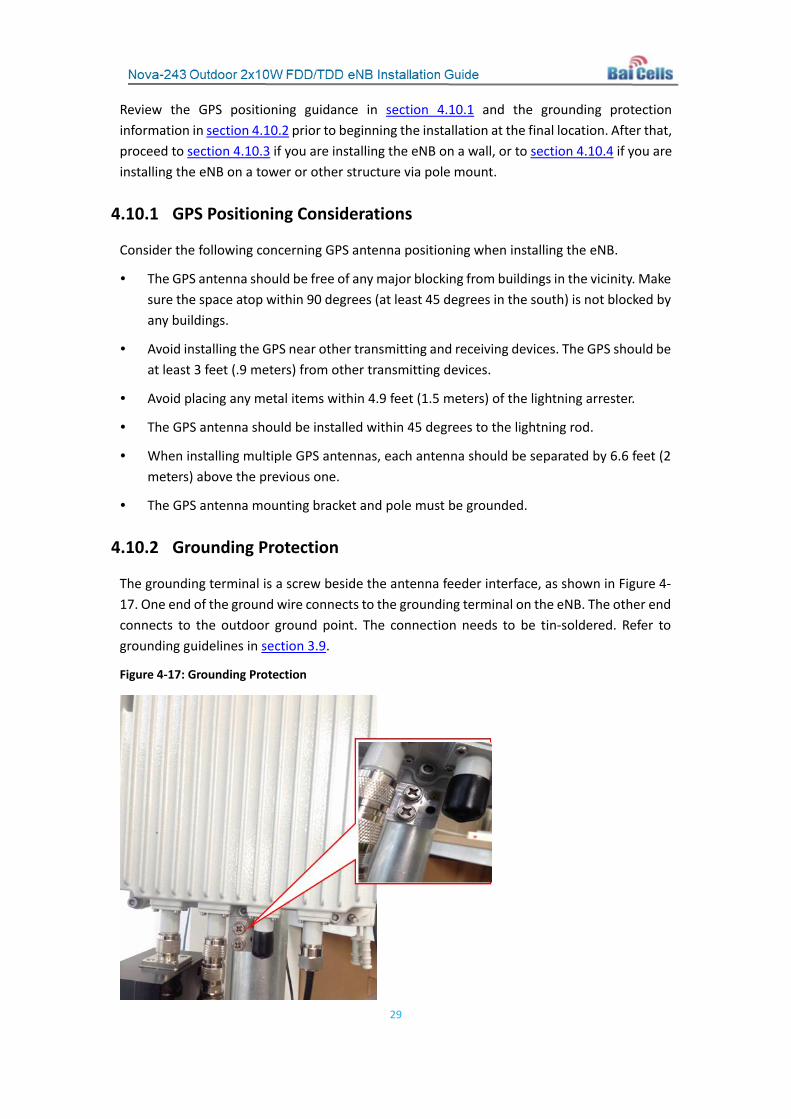
4.10.2 Grounding Protection
The grounding terminal is a screw beside the antenna feeder interface, as shown in Figure 4-17. One end of the ground wire connects to the grounding terminal on the eNB. The other end connects to the outdoor ground point. The connection needs to be tin-soldered. Refer to grounding guidelines in section 3.9.
Figure 4-17: Grounding Protection

30
4.10.3 Install eNB and RF Antenna
Keep the RF cable length between the eNB and antenna as short as possible to minimize signal attenuation. Typically, the eNB will be located within a few feet/meters from the antenna. Only one antenna may be connected to a single Nova-243 eNB.
Operators can use an omnidirectional (“omni”) antenna or a directional antenna with the Baicells eNB. An omni antenna covers a full 360 degrees, while a directional antenna radiates in a specific direction based on angle (e.g., 45°, 90°, etc).
Note: Baicells does not manufacture antenna components; please refer to the list of distributors on the Baicells website: https://na.Baicells.com/where-to-buy/. Make sure to match the frequency range of the antenna with the eNB, and consult the regulatory rules concerning output power specific to your location.
This section explains how to install an omni or directional antenna on an outdoor structure.
For an omni installation refer to section 4.10.3.1. For a directional antenna installation, refer to section 4.10.3.2 (tower, pole). Additional information concerning roof installations is provided in section 4.10.3.3 (roof).
4.10.3.1 Install Omnidirectional Antenna
Following are guidelines for installing an omnidirectional antenna at the cell site.
• The mounting pole diameter must be between 1.4 inches to 2 inches (35 to 50 millimeters). Typically, operators use a 2-inch/50-mm round, steel-made pole.
• The top of the pole and the clamp beneath the antenna should be at the same level once the omni is installed on the pole.
• For optimal performance, ensure the omni antenna is precisely vertical.
• The top of the antenna should fall within the 45-degrees safety angle towards the lightning rod.
• There should be no metal objects within 3.3 feet (1 meter) of the omni antenna. Use an independent lightning rod that is high enough to keep all antennas under its protection cover.
• Ensure the antenna is high enough to meet the coverage requirements specified in the operator’s network design plan.
If it is not possible to install an independent lightning rod due to environmental limitations, ensure that the pole supporting the lightning rod is at least 3.3 feet (1 meter) away from the omni antenna. Follow standard transport procedures to hoist the antenna to the target location.
Once the antenna and eNB unit are installed securely in the proper position, verify grounding and lightning protection. Apply waterproofing as explained in section 4.10.6 of this document.

31
4.10.3.2 Install Directional Antenna on Tower
Following are guidelines for installing a directional antenna at the cell site.
• First, assemble the antenna and the upper and lower racks, as shown in Figure 4-18.
• Follow standard transport procedures to hoist the antenna to the target location.
• Using expansion screws, fix the support pole vertically to the ground (or concrete pillars on a rooftop), and fasten it with steel wires.
• Mount the antenna assembly onto the pole using the installation racks.
Figure 4-18: Assemble Directional Antenna
Once the antenna and eNB are installed securely in the proper position, verify grounding and lightning protection. Apply waterproofing as explained in section 4.10.6 of this document.
4.10.3.3 Install Directional Antenna on Rooftop
When installing a directional antenna on a rooftop, it is easier to install if the antenna andeNB are first attached to a mounting pole that will then be installed on the roof. Begin by wiring the lightning arrester on the top of the mounting pole. Next, install the directional antenna and eNB on the mounting pole with the provided supports. Ensure the directional antenna is vertically plumb with the proper down tilt for desired antenna propagation, as specified in the operator’s network design plan.
In situations where there is a wainscot on the roof and it is taller than 3.9 feet (1.2 meters), attach the fixed mounting pole and antenna on the wall with expansion screws. If the wainscot is less than 3.9 feet (1.2 meters) tall, fix the mounting pole to the wall with expansion screws and attach the base of the mounting pole to an adequate base support frame to stabilize the mounting pole.
32
If the roof does not have a wainscot, use expansion screws to fix the antenna mount on an adequate base support frame, such as concrete, or properly weight the frame to eliminate wind movement. Use guy wires to further stabilize the mounting pole.
Once the antenna and eNB are installed securely in the proper position, verify grounding and lightning protection. Apply waterproofing as explained in section 4.10.6 of this document.
4.10.4 Check eNB Status in Software
The Baicells eNB is designed to be plug-and-play and, therefore, arrives pre-configured. Before you seal and weatherproof the connections on the eNB elements, you will need to log in either to the client GUI or the cloud-based OMC to ensure the eNB status is reported as active. Section 4.10.4.1 explains how to check status using the eNB GUI. Section 4.10.4.2 explains how to check status using the OMC.
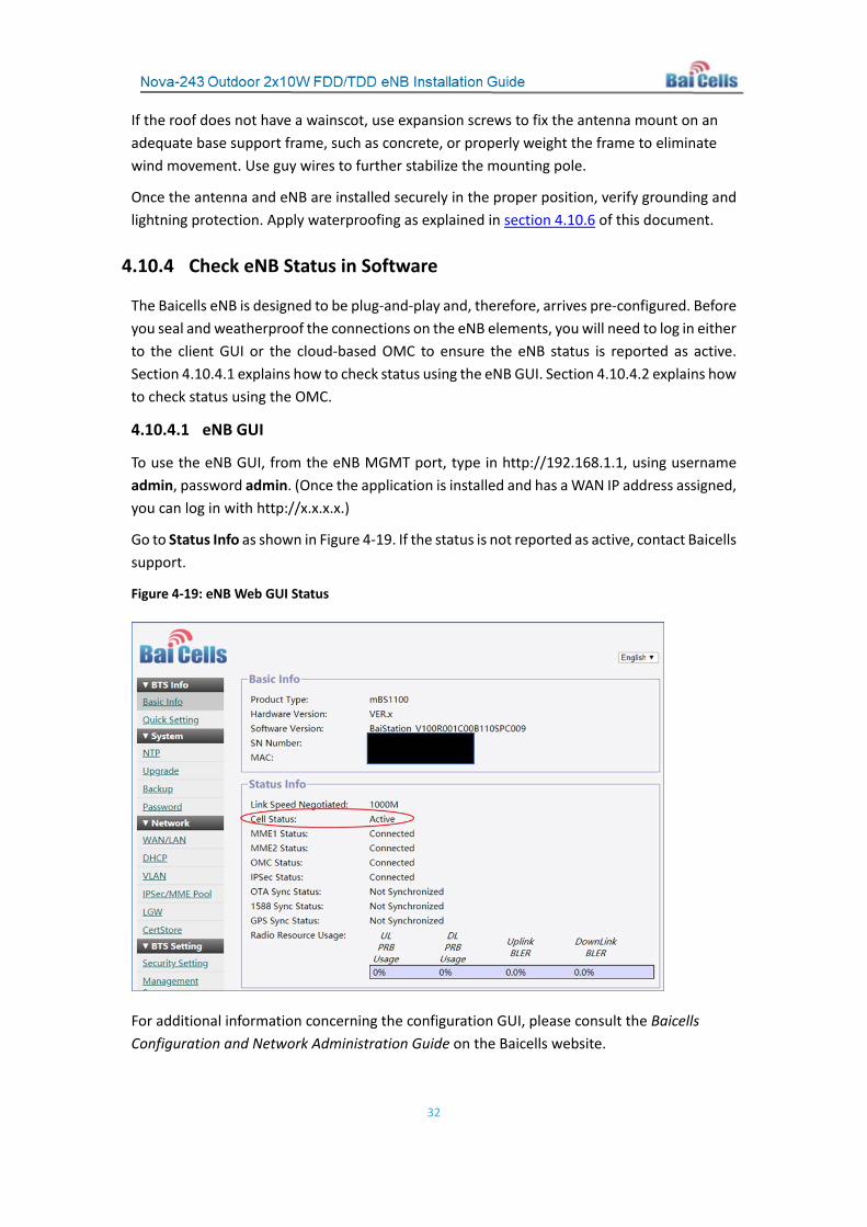
4.10.4.1 eNB GUI
To use the eNB GUI, from the eNB MGMT port, type in http://192.168.1.1, using username admin, password admin. (Once the application is installed and has a WAN IP address assigned, you can log in with http://x.x.x.x.)
Go to Status Info as shown in Figure 4-19. If the status is not reported as active, contact Baicells support.
Figure 4-19: eNB Web GUI Status
For additional information concerning the configuration GUI, please consult the Baicells Configuration and Network Administration Guide on the Baicells website.
33
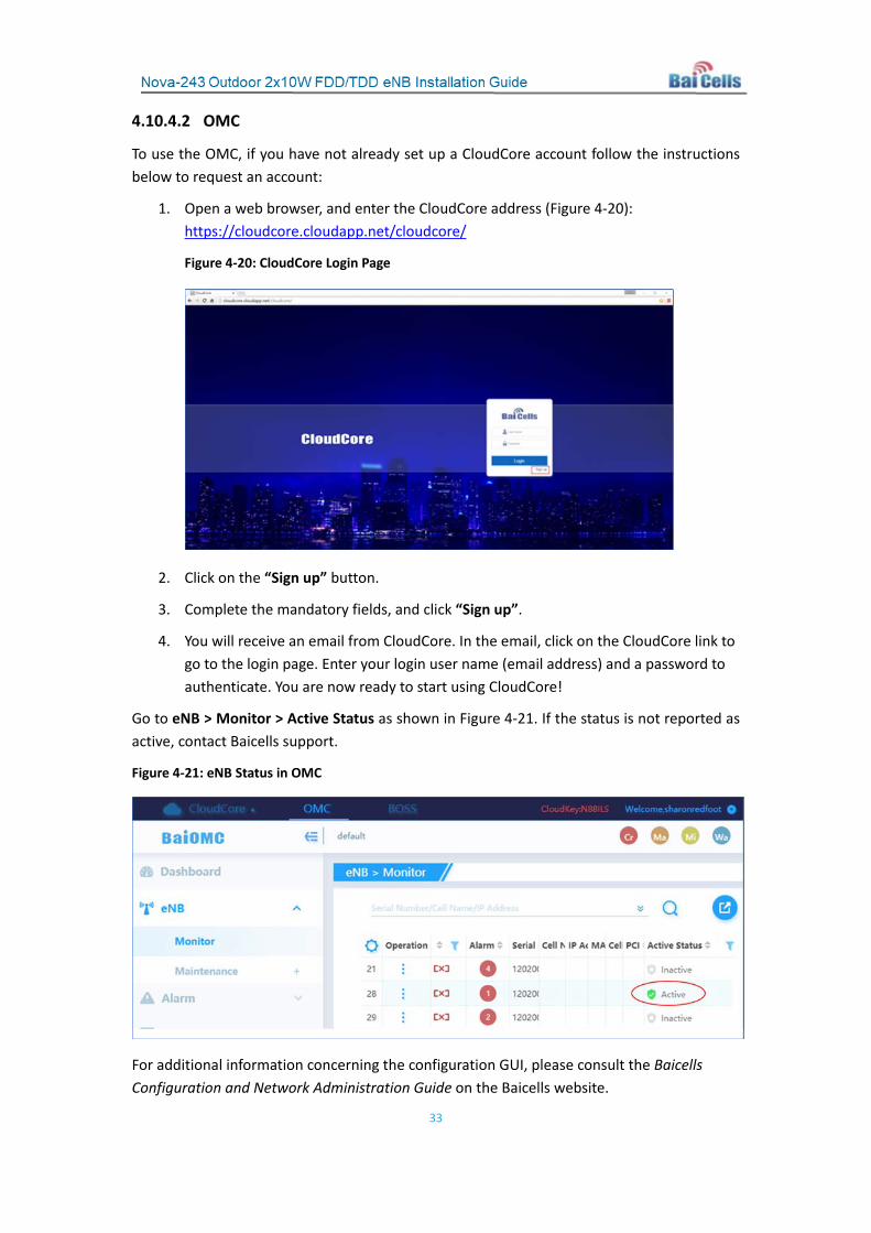
4.10.4.2 OMC
To use the OMC, if you have not already set up a CloudCore account follow the instructions below to request an account:
1. Open a web browser, and enter the CloudCore address (Figure 4-20): https://cloudcore.cloudapp.net/cloudcore/
Figure 4-20: CloudCore Login Page
2. Click on the “Sign up” button.
3. Complete the mandatory fields, and click “Sign up”.
4. You will receive an email from CloudCore. In the email, click on the CloudCore link to go to the login page. Enter your login user name (email address) and a password to authenticate. You are now ready to start using CloudCore!
Go to eNB > Monitor > Active Status as shown in Figure 4-21. If the status is not reported as active, contact Baicells support.
Figure 4-21: eNB Status in OMC
For additional information concerning the configuration GUI, please consult the Baicells Configuration and Network Administration Guide on the Baicells website.
34
4.10.5 Verify Lightning and Grounding Protection
Ensure that all equipment lightning protection and grounding protection measures have been taken. Information about the protection measures is covered in section 3.9 “Grounding and Lightning Protection” and section 4.10.2 “Grounding Protection”. All protection points should be inspected before proceeding to weatherproof the connections.
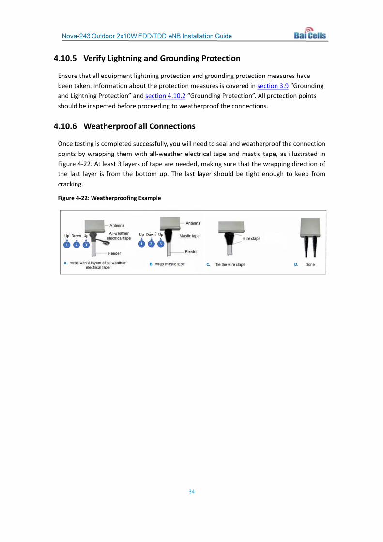
4.10.6 Weatherproof all Connections
Once testing is completed successfully, you will need to seal and weatherproof the connection points by wrapping them with all-weather electrical tape and mastic tape, as illustrated in Figure 4-22. At least 3 layers of tape are needed, making sure that the wrapping direction of the last layer is from the bottom up. The last layer should be tight enough to keep from cracking.
Figure 4-22: Weatherproofing Example

35
Appendix A: Technical Specifications
Hardware Specifications Item Description
LTE Mode FDD/TDD
Frequency Bands FDD: Bands 1/3/7 TDD: Bands 38/40/41/42/48 and customized
Channel Bandwidth 5/10/15/20 MHz Max Output Power 40 dBm / antenna
Receive Sensitivity FDD: -104 dBm TDD Bands 42/48: -101 dBm TDD Bands 38/40/41: -102 dBm
Synchronization Mode GPS 1588v2 (TDD)
Backhaul Mode 1 optical (SF) and 1 RJ-45 Ethernet interface (1 GE) MIMO DL: 2x2
Dimensions (HxWxD)
FDD: 17.3 x 11.8 x 6.3 inches 440 x 300 x 160 mm
TDD: 17.3 x 9.5 x 5.5 inches 440 x 240 x 140 mm
Installation Method Pole or wall mount Antenna External high-gain
Power Consumption FDD: < 180W TDD: < 160W
Power Supply -48V DC, AC adaptor (multi-national standards)
Weight FDD: 4.4 lbs (20 kg) TDD: 26 lbs (12 kg)
Note 1: Different models support different frequencies.
Note 2: The test method for receive sensitivity is proposed by the 3GPP TS 36.104, which is based on 5MHz bandwidth, FRC A1-3 in Annex A.1 (QPSK,R=1/3,25RB) standard.
Software Specifications Item Description
LTE Standard 3GPP Release 9
Peak Rate FDD 20 MHz: 150 Mbps DL, 50 Mbps UL FDD 10 MHz: 75 Mbps DL, 25 Mbps UL

36
Item Description TDD 20 MHz:
- SA1: 80 Mbps DL, 20 Mbps UL - SA2: 112 Mbps DL, 14 Mbps UL
TDD 10 MHz: - SA1: 40 Mbps DL, 10 Mbps UL - SA2: 55 Mbps DL, 5 Mbps UL
User Capacity Maximum 255 (FDD) and 96 (TDD) concurrent users QoS Control 3GPP standard QCI
Modulation
FDD UL: QPSK, 16QAM FDD DL: QPSK, 16QAM, 64QAM TDD UL: QPSK, 16QAM, 64QAM TDD DL: QPSK, 16QAM, 64QAM
Voice Solution CSFB, VoLTE, eSRVCC
Traffic Offload Local IP Access (LIPA) Selected IP Traffic Offload (SIPTO)
SON
Self-Organizing Network supports: Automatic setup Automatic Neighbor Relation (ANR) (TDD) PCI confliction detection
RAN Sharing Supported Network Management Interface
TR069 interface protocol
MTBF ≥ 150000 hours MTTR ≤ 1 hour
Maintenance
Remote/local maintenance Online status management Performance statistics Fault management Local or remote software upgrade Logging Connectivity diagnosis Automatic start and configuration Alarm reporting
KPI recording User information tracing Signaling trace (TDD)

37
Environmental Specifications Item Description Operating Temperature -40°F to 131°F / -40°C to 55°C Storage Temperature
-49°F to 158°F / -45 to 70℃
Humidity 5% to 95% Atmospheric Pressure 70 kPa to 106 kPa Ingress Protection Rating IP66 Power Interface Lightning Protection Differential mode: ±10 KA
Common mode: ±20 KA
Global Part Numbers Supported Frequencies Description BRU3510-B4243 Nova-243 10W eNB, Bands 42/43 BRU3510-B41 Nova-243 10W eNB, Bands 40/41
38
Appendix B: Regulatory Compliance
FCC Compliance
This device complies with part 15 of the FCC Rules. Operation is subject to the following two conditions: (1) This device may not cause harmful interference, and (2) this device must accept any interference received, including interference that may cause undesired operation.
Any Changes or modifications not expressly approved by the party responsible for compliance could void the user's authority to operate the equipment.
This equipment has been tested and found to comply with the limits for a Class B digital
device, pursuant to part 15 of the FCC Rules. These limits are designed to provide reasonable protection against harmful interference in a residential installation. This equipment generates uses and can radiate radio frequency energy and, if not installed and used in accordance with the instructions, may cause harmful interference to radio communications. However, there is no guarantee that interference will not occur in a particular installation.
If this equipment does cause harmful interference to radio or television reception, which can be determined by turning the equipment off and on, the user is encouraged to try to correct the interference by one or more of the following measures:
Reorient or relocate the receiving antenna.
Increase the separation between the equipment and receiver.
Connect the equipment into an outlet on a circuit different from that to which the receiver is connected.
Consult the dealer or an experienced radio/TV technician for help.
Warning This equipment complies with FCC radiation exposure limits set forth for an
uncontrolled environment. This equipment should be installed and operated with minimum distance 50 cm between the radiator & your body.

39
IC Compliance
This device complies with Industry Canada license-exempt RSS standard(s).
Operation is subject to the following two conditions:
(1) This device may not cause interference.
(2) This device must accept any interference, including interference that may cause undesired operation of the device.
Le present appareil est conforme aux CNR d'Industrie Canada applicables aux appareils radio exempts de licence. L'exploitation est autorisée aux deux conditions suivantes:
(1) l'appareil ne doit pas produire de brouillage, et
(2) l'utilisateur de l'appareil doit accepter tout brouillage radioélectrique subi, même si le Brouillage est susceptible d'en compromettre le fonctionnement.
The antenna(s) used for this transmitter must be installed to provide a separation distance of at least 50 cm from all persons and must not be collocated or operating in conjunction with any other antenna or transmitter, End-Users must be provided with transmitter operation conditions for satisfying RF exposure compliance.

40
Appendix C: FAQs If you have questions, please check the list of frequently asked questions (FAQs) on the Baicells support website or the Facebook support forum.
• Baicells support website - https://na.Baicells.com/support/
• Baicells support forum on Facebook - https://www.facebook.com/groups/Baicellsoperatorsupportgroup/


