machines Article Novel Integration of CAPP in a G-Code Generation Module Using Macro Programming for CNC Application Trung Kien Nguyen 1 , Lan Xuan Phung 1, * and Ngoc-Tam Bui 1,2, * 1 School of Mechanical Engineering, Hanoi University of Science and Technology, No.1 DaiCoViet Rd, Hanoi 10000, Vietnam; [email protected]2 College of Systems Engineering and Science, Shibaura Institute of Technology, Tokyo 135-8548, Japan * Correspondence: [email protected] (L.X.P.); [email protected] (N.-T.B.); Tel.: +84-935-888-435 (L.X.P.) Received: 7 September 2020; Accepted: 29 September 2020; Published: 12 October 2020 Abstract: In the modern manufacturing industry, the role of computer-aided process planning (CAPP) is becoming increasingly crucial. Through the application of new technologies, experience, and intelligence, CAPP is contributing to the automation of manufacturing processes. In this article, the integration of a proposed CAPP system that is named as BKCAPP and G-code generation module provides a completed CAD–CAPP–CNC system that does not involve any manual processing in the CAM modules. The BKCAPP system is capable of automatically performing machining feature and operation recognition processes from design features in three-dimensional (3D) solid models, incorporating technical requirements such as the surface roughness, geometric dimensions, and tolerance in order to provide process planning for machining processes, including information on the machine tools, cutting tools, machining conditions, and operation sequences. G-code programs based on macro programming are automatically generated by the G-code generation module on the basis of the basic information for the machining features, such as the contour shape, basic dimensions, and cutting information obtained from BKCAPP. The G-code generation module can be applied to standard machining features, such as faces, pockets, bosses, slots, holes, and contours. This novel integration approach produces a practical CAPP method enabling end users to generate operation consequences and G-code files and to customize specific cutting tools and machine tool data. In this paper, a machining part consisting of basic machining features was used in order to describe the method and verify its implementation. Keywords: CAPP; G-code generation; macro programming; machining feature; CNC machining 1. Introduction Nowadays, computer numerical control (CNC) is widely used in production industries, since various curve shape components can be produced with CNC machines with high efficiency and high quality [1,2]. CNC machines are also essential components of flexible manufacturing systems (FMS) and computer-integrated manufacturing (CIM) systems, in which manufacturing automation is utilized to achieve high productivity [3]. In any production system, process planning is an efficient way to increase quality and reduce manufacturing times [4]. The effects of process planning on production capacity and revenue increases have also been analyzed [5]. Additionally, CNC machining performance strongly depends on the cutting parameters that has been determined and assessed through complicated tasks, time-consuming the processes, and a high level of required engineering from calculation, simulation, or experimental works [6–9]. The recent development of Machines 2020, 8, 61; doi:10.3390/machines8040061 www.mdpi.com/journal/machines
Transcript
machines
Article
Novel Integration of CAPP in a G-Code GenerationModule Using Macro Programming forCNC Application
Trung Kien Nguyen 1, Lan Xuan Phung 1,* and Ngoc-Tam Bui 1,2,*1 School of Mechanical Engineering, Hanoi University of Science and Technology, No.1 DaiCoViet Rd,
Hanoi 10000, Vietnam; [email protected] College of Systems Engineering and Science, Shibaura Institute of Technology, Tokyo 135-8548, Japan* Correspondence: [email protected] (L.X.P.); [email protected] (N.-T.B.);
Tel.: +84-935-888-435 (L.X.P.)
Received: 7 September 2020; Accepted: 29 September 2020; Published: 12 October 2020�����������������
Abstract: In the modern manufacturing industry, the role of computer-aided process planning(CAPP) is becoming increasingly crucial. Through the application of new technologies, experience,and intelligence, CAPP is contributing to the automation of manufacturing processes. In this article,the integration of a proposed CAPP system that is named as BKCAPP and G-code generationmodule provides a completed CAD–CAPP–CNC system that does not involve any manual processingin the CAM modules. The BKCAPP system is capable of automatically performing machiningfeature and operation recognition processes from design features in three-dimensional (3D) solidmodels, incorporating technical requirements such as the surface roughness, geometric dimensions,and tolerance in order to provide process planning for machining processes, including information onthe machine tools, cutting tools, machining conditions, and operation sequences. G-code programsbased on macro programming are automatically generated by the G-code generation module on thebasis of the basic information for the machining features, such as the contour shape, basic dimensions,and cutting information obtained from BKCAPP. The G-code generation module can be applied tostandard machining features, such as faces, pockets, bosses, slots, holes, and contours. This novelintegration approach produces a practical CAPP method enabling end users to generate operationconsequences and G-code files and to customize specific cutting tools and machine tool data. In thispaper, a machining part consisting of basic machining features was used in order to describe themethod and verify its implementation.
Nowadays, computer numerical control (CNC) is widely used in production industries,since various curve shape components can be produced with CNC machines with high efficiencyand high quality [1,2]. CNC machines are also essential components of flexible manufacturingsystems (FMS) and computer-integrated manufacturing (CIM) systems, in which manufacturingautomation is utilized to achieve high productivity [3]. In any production system, process planningis an efficient way to increase quality and reduce manufacturing times [4]. The effects of processplanning on production capacity and revenue increases have also been analyzed [5]. Additionally,CNC machining performance strongly depends on the cutting parameters that has been determinedand assessed through complicated tasks, time-consuming the processes, and a high level of requiredengineering from calculation, simulation, or experimental works [6–9]. The recent development of
computer software programs such as computer-aided design (CAD), computer-aided engineering(CAE), and computer-aided manufacturing (CAM) software has provided effective tools for partsdesign and manufacture. However, process planning was previously based mainly on engineers’experience and expertise. Computer-aided process planning (CAPP) acts as a bridge between design andmanufacturing in a CIM environment. CAPP involves a computer-converted module that incorporatesthe parts’ technical requirements and other information (e.g., relating to the materials, stock forms,and production types) to form operation sequences that are incorporated with process descriptions,such as descriptions for machine tools, cutting tools, and other equipment [10]. Process planning canbe used for many purposes, such as for generating cutting toolpaths in computer-aided manufacturing(CAM) software, for scheduling manufacturing plans, and for production resource management.A CAPP system not only helps to reduce preparation times, but also helps to enhance productivityan automated factory [10,11]. There are two main methods in CAPP: (1) variant and (2) generativemethods. In the first type, process planning is achieved by identifying and retrieving an existingplan for a similar part and applying certain modifications to form a new process plan. Althoughthe programming technique used with this method is simple, optimization is not easy to achievein many processes and the implementation quality still depends on the knowledge and skills ofthe engineers [12]. With generative method, process planning is implemented through technologydatabases, technology rules and constraints, and mathematical models combined with selectionmethods and optimal calculations [13]. Although it is difficult to develop, the generative methodcan perform process planning in detail and is easy to integrate with CAD–CAM–CNC systems.The generative method was applied in this research, with the main aim of creating a process planningmethod that is as detailed as possible and able to be integrated with a CAD–CAM–CNC system. In aCAPP system, a foundation method is necessary for machining feature recognition, machine tooland cutting tool selection, and machining operation procedures (process planning). Recent studieshave shown that machining feature recognition methods only provide basic geometric informationrather than complete information for the technical requirements, geometric intersection relationshipsand contour shape definition, which are important in process planning [14,15]. Feature recognitionmethods mainly focus on 2.5D features, such as slots, steps, and holes, but not on hybrid machiningfeatures, such as contour pockets with islands [16]. A workpiece’s technical requirements are mostlydefined through the user interface for each feature or through separated procedures, thus diminishingthe integrity of the CAD–CAPP connection [17,18]. The cutting tool selection methods have notbeen comprehensively evaluated using multiple criteria and they are not suitable for large-databasesystems with many types and sizes of cutting tools [19]. The methods used to select machine andcutting tools do not usually involve a flexible connection to the manufacturing database for eachfactory. Moreover, some processing parameters related to heat treatment, stock preparation methods,and product types are not considered in machining operation recognition and cutting tool selectionprocesses [20]. Therefore, the selection results would not be adequate for practical applications. In themost recent studies, CAPP systems were mainly built to create a connection between CAD and CAPPsystems through machining feature recognition systems using commercial three-dimensional (3D)CAD software or neutral CAD files [21,22]. The engineers manually applied the results from CAPPsystems to generate the toolpaths for each machining feature in commercial CAM software. Therehave not been many studies on the automatic integration of CAD and CAPP with a CAM module.To create an integrated CAD–CAPP–CNC system, it is necessary to establish a bridge between CAPPand G-code programs, which are directly generated during the process planning in the CAPP system.However, such connections are still limited, since G-code files are mainly based on manual processingor are processed using commercial CAM software. Generally, three basic method types are usedto create a G-code file for CNC machines: (1) the traditional manual programming method, (2) theautomatic method, and (3) macro or parametric programming methods. The first method uses basicG-code commands and cycles for manual programming. This method is difficult to use for automatedprogramming, since it requires a numerical coordinate for every programming point in each G-code
Machines 2020, 8, 61 3 of 16
block. The automatic method uses CAD and CAM software to create G-code files on the basis oftoolpath strategies created by users. The programming function that uses application programminginterface (API) features inside CAM software is not fully modifiable. Therefore, this method is noteasy to integrate with a CAD–CAPP system. Macro or parametric programming methods are CNCprogramming methods that are based on defined parameters, which are normally the geometricparameters of machining features [23,24]. These parameters can be easily extracted from the CAPPmodule through machining feature recognition. Therefore, this method can be integrated withCAD-CAPP systems.
This paper proposes a CAPP system, named BKCAPP, containing basic recognition modulesbased on the development of identification and selection methods, as well as a process planning systemcombined with an automatic G-code generation module based on macro CNC programming. A samplepart was selected in order to evaluate the system’s implementation and effectiveness. The geometricaland technological information for each machining feature extracted from the CAPP system was usedin the automatic formation of CNC programs. Each machining feature of a part has a CNC subroutinein macro programming. The main program uses subroutines in the machining sequence determinedby BKCAPP in order to complete the machining of the part. The G-code generation module can alsobe used independently in manual programing by providing the parameters of machining features.If there is a change in the geometry of a workpiece then the end users simply provide a different set offeature parameters to change the toolpaths. On the basis of this advantage of CNC programming interms of the parameter selection method, this study established a new set of commands and functionsthat use feature parameters extracted from CAPP modules to directly generate the machining programfor the entire workpiece. The results are a fundamental step forward for automatic CAD–CAPP–CNCintegration, which creates a process planning and G-code files with high efficiency and withouttime-consuming processes in CAM software.
2. Procedure and Implementation Approach
2.1. Principle of Proposed Approach
Figure 1 presents a diagram describing the automatic process used to generate G-code filesfrom a 3D solid model in *.sldprt format. First, from a 3D solid model of the part designed incommercial CAD and CAM software, the geometrical and technical requirement data are extracted.On the basis of extracted geometrical data, the rule-based method is then applied for machiningfeature recognition. In the next step, the technical requirement is extracted and used as input datafor machining operation recognition and machining step separation. The whole process of extractionand recognition proceeds automatically. The intermediate and final extraction and recognition resultsare saved to the database in a Microsoft SQL server for use in subsequent processing steps in processplanning, such as in cutting tools, machine tool selection, and operation sequence generation. At thisstage, the automatic connection between CAD and CAPP is established. The G-code, which is used forCNC machining for each operation, can be automatically created with the G-code generation moduleon the basis of process planning generation results and geometrical data extraction. The G-code file forthe whole part is generated by adding all G-code segments for each operation. Therefore, the integratedCAD–CAPP–CNC system is automatically constructed G-code files for CNC machining from a 3Dsolid model. This work focuses on developing a CAPP system, called BKCAPP, which has functionalmodules that include feature extraction and machining feature recognition, machining operationrecognition, cutting tool selection, machine tool selection, and operation sequence generation modules.A database is used for the modules to store extraction data, recognition rules, machining conditiontypes, cutting tool and machine tool libraries, and intermediate and final results in the calculation andprocessing stages.
Machines 2020, 8, 61 4 of 16Machines 2020, 8, x 4 of 16
Figure 1. Principles of the integrated computer-aided design (CAD)–computer-aided process
planning (CAPP)– computer numerical control (CNC) G-code flow.
2.2. Extraction Process
Extraction process for geometry data: In the data extraction process, it is necessary to extract all
geometrical data, including the modeling method and all dimensions for each unit feature of the 3D
solid model. The following seven data types were determined in order to fully understand the
modeling method of the design features, except for the hole feature, as presented in Table 1. All seven
data types are extracted and used as inputs for the machining feature recognition step of the design
feature.
The hole feature built from the Hole Wizard design feature in SolidWorks can be easily extracted
with up to 25 different parameters by using the GetDefinition function of the
WizardHoleFeatureData2 feature. The specific dimensions and contour shapes of each unit feature
are also important for the determination of machining processes, such as machine tools, cutting tools,
cutting data selection, and G-code generation, in order to determine the feature creation types. The
most important extracted dimensions include the depth, width, and length of a feature. For the
complex pocket compositions of islands, which are protrusion or boss-extrude design features
created inside cut-extrude, other specific dimensions are extracted, such as the minimal dimensions
between walls, the minimal dimensions between a wall and island, and the dimensions between two
protrusion islands in a pocket. The base face and contours of machining features are also obtained.
The open characteristics of each feature are also determined in this step. These open directions are
also called the possible tool access directions (pTADs) of a feature. For example, the feature presented
in Table 1 has two pTADs, which are combined with the base face’s characteristics to select the main
machining direction or main tool access direction (TAD) for the operation sequence and G-code
generation process.
Technical requirements for the extraction process: The set of technical requirements of a
machining part is another factor that determines the quality of the part machining process. This
proposed process also considers each feature and its technical requirements, meaning recognition of
the technical requirements is then needed. In this study, the most important technical requirements
for the machining process are the surface roughness, geometrical dimensioning, and tolerancing.
Table 2 presents some examples of technical requirement extraction.
The extraction process for the relationships between machining features: In machining feature
recognition, the interactions between features are complex problems. A feature can have adjacent or
volume interactions with other features. The existence of these interactions sometimes changes the
machining process of the feature. Therefore, it is necessary to identify the relationships between
Figure 1. Principles of the integrated computer-aided design (CAD)–computer-aided process planning(CAPP)–computer numerical control (CNC) G-code flow.
2.2. Extraction Process
Extraction process for geometry data: In the data extraction process, it is necessary to extractall geometrical data, including the modeling method and all dimensions for each unit feature ofthe 3D solid model. The following seven data types were determined in order to fully understandthe modeling method of the design features, except for the hole feature, as presented in Table 1.All seven data types are extracted and used as inputs for the machining feature recognition step of thedesign feature.
Table 1. Definition of seven geometrical data extraction types.
1. Feature type Real feature type for each unit feature, such as extrude, sweep, or revolve, in a bossor cut type.
2. Sketch type Sketch shape types, such as circular, rectangular, polylineal, and splined.
3. Sketch directiontype
Line types for most design feature cases, such as line, circular, and spline, for sweepdesign features.
4. Condition type
Most important characteristics of geometrical extraction data. For each designfeature, it is necessary to determine which characteristics are closed or open andblind or through with cut-extrude-type design features, and whether they are freeor interact with any boss-extrude type design features.
5. Draft type Existence of draft shape of design feature to determine no draft, draft+,or draft type.
6. Island type Existence of the island inside the design feature.
7. Direct member By checking the reverse direction of a normal vector of a sketch with one of thepossible tool access directions to determine the same or a different direction.
machining features. These data are important for recognizing the right machining features and for generating suitable operation sequences with machining constraints in the process planning stage.
Table 1. Definition of seven geometrical data extraction types.
1. Feature type Real feature type for each unit feature, such as extrude, sweep, or revolve, in a boss or cut type.
2. Sketch type Sketch shape types, such as circular, rectangular, polylineal, and splined. 3. Sketch direction type
Line types for most design feature cases, such as line, circular, and spline, for sweep design features.
4. Condition type
Most important characteristics of geometrical extraction data. For each design feature, it is necessary to determine which characteristics are closed or open and blind or through with cut-extrude-type design features, and whether they are free or interact with any boss-extrude type design features.
5. Draft type Existence of draft shape of design feature to determine no draft, draft+, or draft type.
6. Island type Existence of the island inside the design feature.
7. Direct member By checking the reverse direction of a normal vector of a sketch with one of the possible tool access directions to determine the same or a different direction.
2. Sketch type (Rectangular)
7. Direction Member (Same direction)
1. Feature type (Cut-Extrude)
6. Island type(No island)
4. Condition type (Blind, one opened side)
pTAD 1
Opened side (pTAD 2)
3. Sketch direction type(Perpendicular line)
5. Draft type (No draft)
pTAD: Possible Tool Access Direction
Table 2. Examples of technical requirement extraction data.
Example Requirement Type Value (µm) Datum Base 1 Base 2 Level
Surface roughness
Ra 1.25 - F1 - 7
Dimension accuracy
Dimension 25
- F1 F2 11 Dimension tolerance
+0.06
–0.05
2.3. Recognition Process and Process Planning Generation
Machining feature recognition: The machining feature recognition process consists of two different procedures. Figure 2 gives examples of recognition rules for both the Hole Wizard tool and a feature without Hole Wizard. The machining direction is also defined by the TAD and the base face. The first procedure is used for the Hole Wizard feature and the second is applied for the other features except for Hole Wizard. The rules were constructed to recognize hole machining features on the basis of the values of specific parameters in the list of design parameters extracted from the Hole Wizard design feature. According to these feature recognition rules, a design feature can be recognized based on several machining features, such as drill holes, drill holes and countersinks, and drill holes and
Machines 2020, 8, 61 5 of 16
The hole feature built from the Hole Wizard design feature in SolidWorks can be easily extractedwith up to 25 different parameters by using the GetDefinition function of the WizardHoleFeatureData2feature. The specific dimensions and contour shapes of each unit feature are also important for thedetermination of machining processes, such as machine tools, cutting tools, cutting data selection,and G-code generation, in order to determine the feature creation types. The most important extracteddimensions include the depth, width, and length of a feature. For the complex pocket compositions ofislands, which are protrusion or boss-extrude design features created inside cut-extrude, other specificdimensions are extracted, such as the minimal dimensions between walls, the minimal dimensionsbetween a wall and island, and the dimensions between two protrusion islands in a pocket. The baseface and contours of machining features are also obtained. The open characteristics of each feature arealso determined in this step. These open directions are also called the possible tool access directions(pTADs) of a feature. For example, the feature presented in Table 1 has two pTADs, which are combinedwith the base face’s characteristics to select the main machining direction or main tool access direction(TAD) for the operation sequence and G-code generation process.
Technical requirements for the extraction process: The set of technical requirements of a machiningpart is another factor that determines the quality of the part machining process. This proposedprocess also considers each feature and its technical requirements, meaning recognition of the technicalrequirements is then needed. In this study, the most important technical requirements for the machiningprocess are the surface roughness, geometrical dimensioning, and tolerancing. Table 2 presents someexamples of technical requirement extraction.
Table 2. Examples of technical requirement extraction data.
Example Requirement Type Value (µm) Datum Base 1 Base 2 Level
machining features. These data are important for recognizing the right machining features and for generating suitable operation sequences with machining constraints in the process planning stage.
Table 1. Definition of seven geometrical data extraction types.
1. Feature type Real feature type for each unit feature, such as extrude, sweep, or revolve, in a boss or cut type.
2. Sketch type Sketch shape types, such as circular, rectangular, polylineal, and splined. 3. Sketch direction type
Line types for most design feature cases, such as line, circular, and spline, for sweep design features.
4. Condition type
Most important characteristics of geometrical extraction data. For each design feature, it is necessary to determine which characteristics are closed or open and blind or through with cut-extrude-type design features, and whether they are free or interact with any boss-extrude type design features.
5. Draft type Existence of draft shape of design feature to determine no draft, draft+, or draft type.
6. Island type Existence of the island inside the design feature.
7. Direct member By checking the reverse direction of a normal vector of a sketch with one of the possible tool access directions to determine the same or a different direction.
2. Sketch type (Rectangular)
7. Direction Member (Same direction)
1. Feature type (Cut-Extrude)
6. Island type(No island)
4. Condition type (Blind, one opened side)
pTAD 1
Opened side (pTAD 2)
3. Sketch direction type(Perpendicular line)
5. Draft type (No draft)
pTAD: Possible Tool Access Direction
Table 2. Examples of technical requirement extraction data.
Example Requirement Type Value (µm) Datum Base 1 Base 2 Level
Surface roughness
Ra 1.25 - F1 - 7
Dimension accuracy
Dimension 25
- F1 F2 11 Dimension tolerance
+0.06
–0.05
2.3. Recognition Process and Process Planning Generation
Machining feature recognition: The machining feature recognition process consists of two different procedures. Figure 2 gives examples of recognition rules for both the Hole Wizard tool and a feature without Hole Wizard. The machining direction is also defined by the TAD and the base face. The first procedure is used for the Hole Wizard feature and the second is applied for the other features except for Hole Wizard. The rules were constructed to recognize hole machining features on the basis of the values of specific parameters in the list of design parameters extracted from the Hole Wizard design feature. According to these feature recognition rules, a design feature can be recognized based on several machining features, such as drill holes, drill holes and countersinks, and drill holes and
Dimensionaccuracy
Dimension 25- F1 F2 11
Dimensiontolerance
+0.06–0.05
The extraction process for the relationships between machining features: In machining featurerecognition, the interactions between features are complex problems. A feature can have adjacentor volume interactions with other features. The existence of these interactions sometimes changesthe machining process of the feature. Therefore, it is necessary to identify the relationships betweenmachining features. These data are important for recognizing the right machining features and forgenerating suitable operation sequences with machining constraints in the process planning stage.
2.3. Recognition Process and Process Planning Generation
Machining feature recognition: The machining feature recognition process consists of two differentprocedures. Figure 2 gives examples of recognition rules for both the Hole Wizard tool and a featurewithout Hole Wizard. The machining direction is also defined by the TAD and the base face. The firstprocedure is used for the Hole Wizard feature and the second is applied for the other features exceptfor Hole Wizard. The rules were constructed to recognize hole machining features on the basis of thevalues of specific parameters in the list of design parameters extracted from the Hole Wizard designfeature. According to these feature recognition rules, a design feature can be recognized based onseveral machining features, such as drill holes, drill holes and countersinks, and drill holes and tapping.For other design feature types, recognition rules are established and saved in the database on the basisof seven extracted information items, as shown in Table 1. This can determine whether a machining
Machines 2020, 8, 61 6 of 16
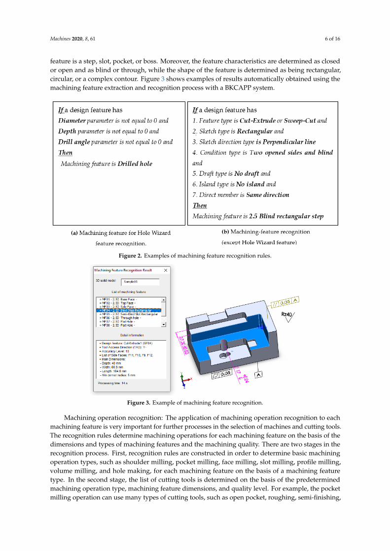
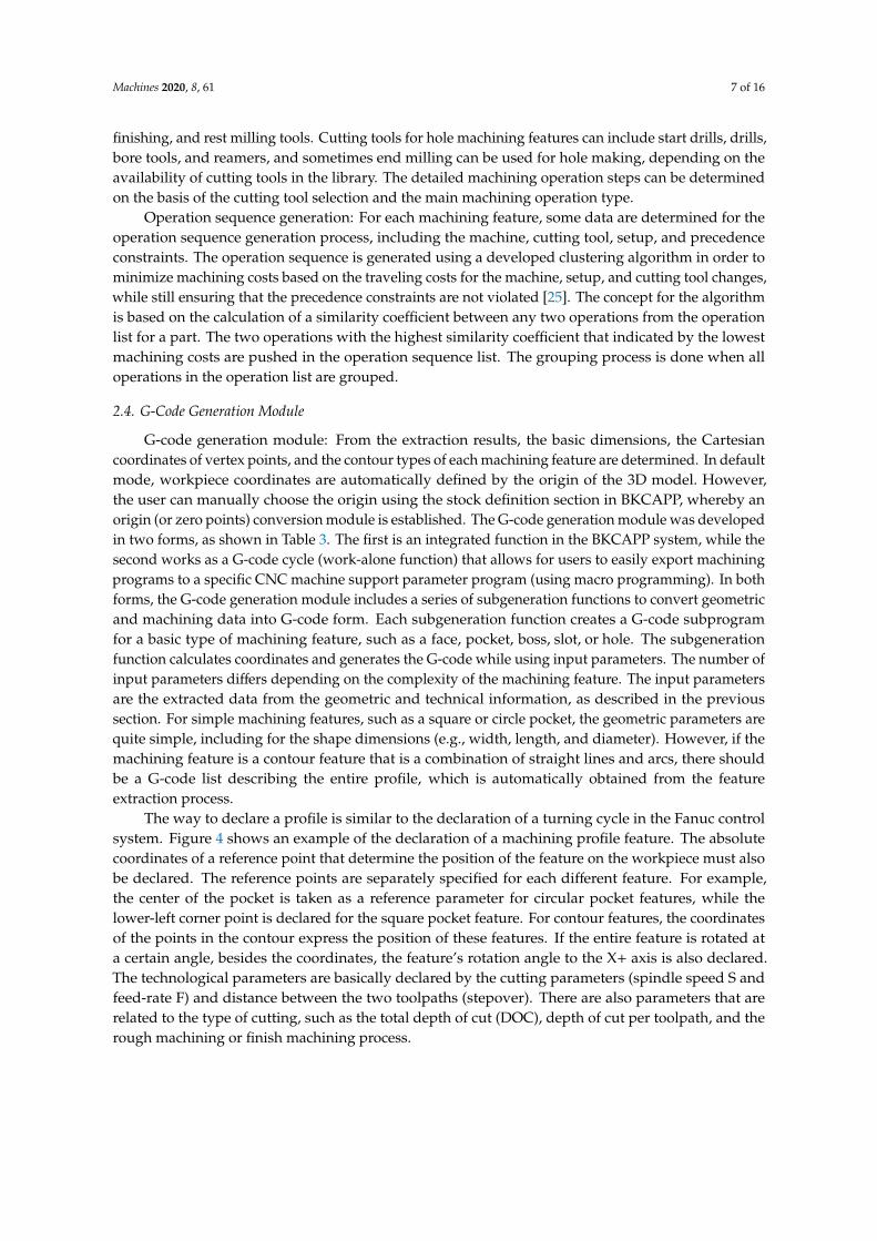
feature is a step, slot, pocket, or boss. Moreover, the feature characteristics are determined as closedor open and as blind or through, while the shape of the feature is determined as being rectangular,circular, or a complex contour. Figure 3 shows examples of results automatically obtained using themachining feature extraction and recognition process with a BKCAPP system.
tapping. For other design feature types, recognition rules are established and saved in the database on the basis of seven extracted information items, as shown in Table 1. This can determine whether a machining feature is a step, slot, pocket, or boss. Moreover, the feature characteristics are determined as closed or open and as blind or through, while the shape of the feature is determined as being rectangular, circular, or a complex contour. Figure 3 shows examples of results automatically obtained using the machining feature extraction and recognition process with a BKCAPP system.
Figure 2. Examples of machining feature recognition rules.
Figure 3. Example of machining feature recognition.
Machining operation recognition: The application of machining operation recognition to each machining feature is very important for further processes in the selection of machines and cutting tools. The recognition rules determine machining operations for each machining feature on the basis of the dimensions and types of machining features and the machining quality. There are two stages in the recognition process. First, recognition rules are constructed in order to determine basic machining operation types, such as shoulder milling, pocket milling, face milling, slot milling, profile milling, volume milling, and hole making, for each machining feature on the basis of a machining feature type. In the second stage, the list of cutting tools is determined on the basis of the
Figure 2. Examples of machining feature recognition rules.
tapping. For other design feature types, recognition rules are established and saved in the database on the basis of seven extracted information items, as shown in Table 1. This can determine whether a machining feature is a step, slot, pocket, or boss. Moreover, the feature characteristics are determined as closed or open and as blind or through, while the shape of the feature is determined as being rectangular, circular, or a complex contour. Figure 3 shows examples of results automatically obtained using the machining feature extraction and recognition process with a BKCAPP system.
Figure 2. Examples of machining feature recognition rules.
Figure 3. Example of machining feature recognition.
Machining operation recognition: The application of machining operation recognition to each machining feature is very important for further processes in the selection of machines and cutting tools. The recognition rules determine machining operations for each machining feature on the basis of the dimensions and types of machining features and the machining quality. There are two stages in the recognition process. First, recognition rules are constructed in order to determine basic machining operation types, such as shoulder milling, pocket milling, face milling, slot milling, profile milling, volume milling, and hole making, for each machining feature on the basis of a machining feature type. In the second stage, the list of cutting tools is determined on the basis of the
Figure 3. Example of machining feature recognition.
Machining operation recognition: The application of machining operation recognition to eachmachining feature is very important for further processes in the selection of machines and cutting tools.The recognition rules determine machining operations for each machining feature on the basis of thedimensions and types of machining features and the machining quality. There are two stages in therecognition process. First, recognition rules are constructed in order to determine basic machiningoperation types, such as shoulder milling, pocket milling, face milling, slot milling, profile milling,volume milling, and hole making, for each machining feature on the basis of a machining featuretype. In the second stage, the list of cutting tools is determined on the basis of the predeterminedmachining operation type, machining feature dimensions, and quality level. For example, the pocketmilling operation can use many types of cutting tools, such as open pocket, roughing, semi-finishing,
Machines 2020, 8, 61 7 of 16
finishing, and rest milling tools. Cutting tools for hole machining features can include start drills, drills,bore tools, and reamers, and sometimes end milling can be used for hole making, depending on theavailability of cutting tools in the library. The detailed machining operation steps can be determinedon the basis of the cutting tool selection and the main machining operation type.
Operation sequence generation: For each machining feature, some data are determined for theoperation sequence generation process, including the machine, cutting tool, setup, and precedenceconstraints. The operation sequence is generated using a developed clustering algorithm in order tominimize machining costs based on the traveling costs for the machine, setup, and cutting tool changes,while still ensuring that the precedence constraints are not violated [25]. The concept for the algorithmis based on the calculation of a similarity coefficient between any two operations from the operationlist for a part. The two operations with the highest similarity coefficient that indicated by the lowestmachining costs are pushed in the operation sequence list. The grouping process is done when alloperations in the operation list are grouped.
2.4. G-Code Generation Module
G-code generation module: From the extraction results, the basic dimensions, the Cartesiancoordinates of vertex points, and the contour types of each machining feature are determined. In defaultmode, workpiece coordinates are automatically defined by the origin of the 3D model. However,the user can manually choose the origin using the stock definition section in BKCAPP, whereby anorigin (or zero points) conversion module is established. The G-code generation module was developedin two forms, as shown in Table 3. The first is an integrated function in the BKCAPP system, while thesecond works as a G-code cycle (work-alone function) that allows for users to easily export machiningprograms to a specific CNC machine support parameter program (using macro programming). In bothforms, the G-code generation module includes a series of subgeneration functions to convert geometricand machining data into G-code form. Each subgeneration function creates a G-code subprogramfor a basic type of machining feature, such as a face, pocket, boss, slot, or hole. The subgenerationfunction calculates coordinates and generates the G-code while using input parameters. The number ofinput parameters differs depending on the complexity of the machining feature. The input parametersare the extracted data from the geometric and technical information, as described in the previoussection. For simple machining features, such as a square or circle pocket, the geometric parameters arequite simple, including for the shape dimensions (e.g., width, length, and diameter). However, if themachining feature is a contour feature that is a combination of straight lines and arcs, there shouldbe a G-code list describing the entire profile, which is automatically obtained from the featureextraction process.
The way to declare a profile is similar to the declaration of a turning cycle in the Fanuc controlsystem. Figure 4 shows an example of the declaration of a machining profile feature. The absolutecoordinates of a reference point that determine the position of the feature on the workpiece must alsobe declared. The reference points are separately specified for each different feature. For example,the center of the pocket is taken as a reference parameter for circular pocket features, while thelower-left corner point is declared for the square pocket feature. For contour features, the coordinatesof the points in the contour express the position of these features. If the entire feature is rotated ata certain angle, besides the coordinates, the feature’s rotation angle to the X+ axis is also declared.The technological parameters are basically declared by the cutting parameters (spindle speed S andfeed-rate F) and distance between the two toolpaths (stepover). There are also parameters that arerelated to the type of cutting, such as the total depth of cut (DOC), depth of cut per toolpath, and therough machining or finish machining process.
Machines 2020, 8, 61 8 of 16
Table 3. Two G-code forms for contour features.
First form (integrated function in BKCAPP system):G65 P1040 Z . . . K . . . H . . . E . . . T . . . B . . . C . . . R . . . M . . . U . . . W . . . F . . . S . . .
Second form (work-alone function):G104 Z . . . K . . . H . . . D . . . E . . . T . . .G105 P . . . Q . . . B . . . C . . . R . . . M . . . U . . . W . . . F . . . S...
- Z: absolute coordinates of profile bottom in Z (+/–);- K: height/depth of the island (+)/pocket (–);- H: tool radius compensation;- D: diameter of cutting tool;- E: pocket machining (E = 1)/island machining (E = 0);- T: tool number;- P: block number start defines a profile;- Q: block number end defines a profile;
- B: step over toolpaths (%tool radius);- C: depth of cut in Z (+);- R: retract plane;- M: maximal depth of cut in XY;- U: depth of cut in XY in finishing step;- W: depth of cut in Z in finishing step;- F: feed rate;- S: spindle speed.
First form (integrated function in BKCAPP system): G65 P1040 Z…K…H…E…T…B…C…R…M…U…W…F…S… Second form (work-alone function): G104 Z…K…H…D…E…T… G105 P…Q…B…C…R…M…U…W…F…S...
- Z: absolute coordinates of profile bottom in Z (+/–); - K: height/depth of the island (+)/pocket (–); - H: tool radius compensation; - D: diameter of cutting tool; - E: pocket machining (E = 1)/island machining (E = 0); - T: tool number; - P: block number start defines a profile; - Q: block number end defines a profile;
- B: step over toolpaths (%tool radius); - C: depth of cut in Z (+); - R: retract plane; - M: maximal depth of cut in XY; - U: depth of cut in XY in finishing step; - W: depth of cut in Z in finishing step;
F: feed rate; S: spindle speed.
Figure 4. Example of contour feature declaration.
Toolpath generation algorithm: The toolpath generation module in CAM software mostly computes the actual coordinates of the tool reference points. In the G-code generation module, the toolpath generation algorithm only computes the start point, points of the profiles, endpoint, and tool radius compensation. On the basis of process planning results, a set of machining processes, machine and cutting tools, cutting conditions, and G-code files is automatically generated. The calculation of the actual toolpath is executed through G41/G42 cutter radius compensation by the CNC controller. When multiple toolpaths are parallel to the profile, the cutter radius compensation value is changed accordingly. With this algorithm generation method, the toolpaths for rough machining are simple and straightforward with fixed forms, similar to toolpaths in manual programing. In the finishing process, the toolpaths are similar to those in CAM software. The straightforward forms help the user in controlling the order and reliability of toolpaths, however the cutting quality is still comparable to that achieved with CAM software. Toolpaths for contour machining feature samples with rough machining and finishing processes are shown in Figure 5. In rough machining, toolpaths are parallel paths to the machining profile (i = 1 ÷ n; n is the total number of contours per cutting layer with the same depth of cut in Z). The coordinates of the programing points on these toolpaths are automatically calculated by changing the cutter radius compensation value Hi corresponding to each ith toolpath on the basis of the total DOC (M), stepover (B), finishing DOC (U), tool diameter (D), and
Toolpath generation algorithm: The toolpath generation module in CAM software mostly computesthe actual coordinates of the tool reference points. In the G-code generation module, the toolpathgeneration algorithm only computes the start point, points of the profiles, endpoint, and tool radiuscompensation. On the basis of process planning results, a set of machining processes, machine andcutting tools, cutting conditions, and G-code files is automatically generated. The calculation ofthe actual toolpath is executed through G41/G42 cutter radius compensation by the CNC controller.When multiple toolpaths are parallel to the profile, the cutter radius compensation value is changedaccordingly. With this algorithm generation method, the toolpaths for rough machining are simpleand straightforward with fixed forms, similar to toolpaths in manual programing. In the finishingprocess, the toolpaths are similar to those in CAM software. The straightforward forms help the userin controlling the order and reliability of toolpaths, however the cutting quality is still comparableto that achieved with CAM software. Toolpaths for contour machining feature samples with roughmachining and finishing processes are shown in Figure 5. In rough machining, toolpaths are parallelpaths to the machining profile (i = 1 ÷ n; n is the total number of contours per cutting layer with thesame depth of cut in Z). The coordinates of the programing points on these toolpaths are automaticallycalculated by changing the cutter radius compensation value Hi corresponding to each ith toolpath onthe basis of the total DOC (M), stepover (B), finishing DOC (U), tool diameter (D), and logic value K(K = 1, 0), as shown in Equation (1). This toolpath generation algorithm produces simple programs forrough machining that can be easily checked, verified, and modified.
Hi(rough) =[M−
D2+ (i− 1)B
]K +
[D2+ U
](1−K) (1)
Machines 2020, 8, 61 9 of 16
In finish machining, the finishing toolpath (i = n + 1) cuts off the finishing DOC to form a machinedprofile with the level of required quality that is determined in the process planning stage. The toolpathsin this step is slightly different than those in rough machining, as entry and exit toolpaths are addedaccording to the curvature radius (R), which is specified by the programmer or by default calculationfrom the G-code generation module. Therefore, programming points for the entry (1→2→3) and exit(3→5→1) toolpaths, as shown in Figure 5b, are calculated on the basis of the geometry of the startprofile segment (P1–P2), the curvature radius, and total DOC. Equations (2)–(6) show the calculation ofthese points’ coordinates based on angle C of the profile segment relative to the X+ axis.
logic value K (K = 1, 0), as shown in Equation (1). This toolpath generation algorithm produces simple programs for rough machining that can be easily checked, verified, and modified.
( ) = − 2 + ( − 1) + 2 + (1 − ) (1)
In finish machining, the finishing toolpath (i = n + 1) cuts off the finishing DOC to form a machined profile with the level of required quality that is determined in the process planning stage. The toolpaths in this step is slightly different than those in rough machining, as entry and exit toolpaths are added according to the curvature radius (R), which is specified by the programmer or by default calculation from the G-code generation module. Therefore, programming points for the entry (1→2→3) and exit (3→5→1) toolpaths, as shown in Figure 5b, are calculated on the basis of the geometry of the start profile segment (P1–P2), the curvature radius, and total DOC. Equations (2)–(6) show the calculation of these points’ coordinates based on angle C of the profile segment relative to the X+ axis.
Figure 5. Toolpaths for (a) rough, and (b) finish machining.
= +2 = +2 (2)
= − 2 ∗ = − 2 ∗ (3)
= + 2 = + 2 (4)
= + ∗ = − ∗ (5) = 2 − = − (6)
where A = 180 − C; C is the angle of the 1st profile segment to unit vector [0,1]u of the X+ axis: = 0 ∗ ( − ) + 1 ∗ ( − ) 1 ∗ ( − ) + ( − ) (7)
3. Results
3.1. Geometry and Technical Data Exaction
Figure 6 shows the main interface of the BKCAPP system, in which the input is a sample of a 3D model with technical requirements in SolidWorks format (*.sldprt), along with some initial manufacturing parameters, such as the product types or the number of parts per year, the stock
(a) (b)
Figure 5. Toolpaths for (a) rough, and (b) finish machining.
X3 =XP1 + XP2
2Y3 =
YP1 + YP2
2(2)
X1 = X3 − 2R ∗ sinA Y1 = Y3 − 2R ∗ cosA (3)
X4 =X1 + X3
2Y4 =
Y1 + Y3
2(4)
X2 = X4 + R ∗ cosA Y2 = Y4 −R ∗ sinA (5)
X5 = 2X4 −X2 Y5 = Y −Y2 (6)
where A = 180◦ − C; C is the angle of the 1st profile segment to unit vector→u [0, 1] of the X+ axis:
cosC =0 ∗ (YP2 −YP1) + 1 ∗ (XP2 −XP1)
1 ∗√(XP2 −XP1) 2 + (YP2 −YP1)
2(7)
3. Results
3.1. Geometry and Technical Data Exaction
Figure 6 shows the main interface of the BKCAPP system, in which the input is a sample ofa 3D model with technical requirements in SolidWorks format (*.sldprt), along with some initialmanufacturing parameters, such as the product types or the number of parts per year, the stockpreparation method, the heat treatment method, the workpiece material and hardness, and a cuttingtool and machine tool library. The BKCAPP system is connected to a database while using a MicrosoftSQL server to retrieve and store the processing and results data. The outputs are the lists of machinesand cutting tools, the process plan, and the G-code files for the machining of parts. The workpiecesample used for the case study has basic technical requirements related to the surface roughness,geometric dimensions, and tolerance. The manufacturing parameters are: S45C steel for the workpiece
Machines 2020, 8, 61 10 of 16
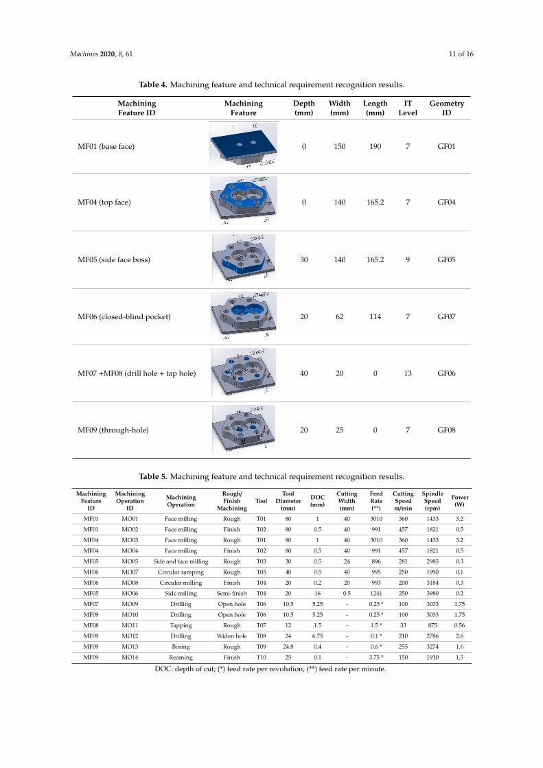
material, small batch production type, forging method for stock preparation, annealing method forheat treatment, a specific machine tool library, and the Sandvik cutting tool library. The processing timefor the machining feature recognition process for the sample is 9 s with the BKCAPP. The machiningfeature recognition module can recognize all features, such as the base face, top face, side faces,pocket, and holes, the basic dimensions and machining accuracy levels for which are described inTable 4. In addition to the basic dimensions of the machining features, the coordinates of points in theprofile of the machining contour features (MF05) at the side faces were also extracted for the G-codegeneration process.
preparation method, the heat treatment method, the workpiece material and hardness, and a cutting tool and machine tool library. The BKCAPP system is connected to a database while using a Microsoft SQL server to retrieve and store the processing and results data. The outputs are the lists of machines and cutting tools, the process plan, and the G-code files for the machining of parts. The workpiece sample used for the case study has basic technical requirements related to the surface roughness, geometric dimensions, and tolerance. The manufacturing parameters are: S45C steel for the workpiece material, small batch production type, forging method for stock preparation, annealing method for heat treatment, a specific machine tool library, and the Sandvik cutting tool library. The processing time for the machining feature recognition process for the sample is 9 s with the BKCAPP. The machining feature recognition module can recognize all features, such as the base face, top face, side faces, pocket, and holes, the basic dimensions and machining accuracy levels for which are described in Table 4. In addition to the basic dimensions of the machining features, the coordinates of points in the profile of the machining contour features (MF05) at the side faces were also extracted for the G-code generation process.
Figure 6. Interface of the BKCAPP system with three-dimensional (3D) part drawing input.
The interaction relationships between machining features were also extracted in order to define constraint inputs to determine the operation sequence. On the basis of machining feature recognition results, the process planning includes a selection of machining processes, machine and cutting tools, and cutting conditions. The optimal operation sequence is established by considering the machining costs and precedence constraints. The operations or steps for each machining feature for the sample presented in Table 5 show that the process planning method involves 11 different machining processes, including rough and finish machining processes, which are determined by the interval of tolerance (IT) level of a machining feature. BKCAPP specifies the cutting tools, conditions, and power for each of these operations, depending on the machine and tool databases. The process planning step for the BKCAPP system takes about 6.3 sec for the sample. The intermediate processing steps and results are all stored in an SQL server.
Figure 6. Interface of the BKCAPP system with three-dimensional (3D) part drawing input.
The interaction relationships between machining features were also extracted in order to defineconstraint inputs to determine the operation sequence. On the basis of machining feature recognitionresults, the process planning includes a selection of machining processes, machine and cutting tools,and cutting conditions. The optimal operation sequence is established by considering the machiningcosts and precedence constraints. The operations or steps for each machining feature for the samplepresented in Table 5 show that the process planning method involves 11 different machining processes,including rough and finish machining processes, which are determined by the interval of tolerance (IT)level of a machining feature. BKCAPP specifies the cutting tools, conditions, and power for each ofthese operations, depending on the machine and tool databases. The process planning step for theBKCAPP system takes about 6.3 s for the sample. The intermediate processing steps and results are allstored in an SQL server.
Machines 2020, 8, 61 11 of 16
Table 4. Machining feature and technical requirement recognition results.
DOC: depth of cut; (*) feed rate per revolution; (**) feed rate per minute.
Machines 2020, 8, 61 12 of 16
3.2. G-Code Generation Module Implementation
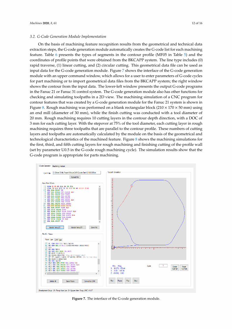
On the basis of machining feature recognition results from the geometrical and technical dataextraction steps, the G-code generation module automatically creates the G-code list for each machiningfeature. Table 6 presents the types of segments in the contour profile (MF05 in Table 5) and thecoordinates of profile points that were obtained from the BKCAPP system. The line type includes (0)rapid traverse, (1) linear cutting, and (2) circular cutting. This geometrical data file can be used asinput data for the G-code generation module. Figure 7 shows the interface of the G-code generationmodule with an upper command window, which allows for a user to enter parameters of G-code cyclesfor part machining or to import geometrical data files from the BKCAPP system; the right windowshows the contour from the input data. The lower-left window presents the output G-code programsin the Fanuc 21 or Fanuc 31 control system. The G-code generation module also has other functions forchecking and simulating toolpaths in a 2D view. The machining simulation of a CNC program forcontour features that was created by a G-code generation module for the Fanuc 21 system is shown inFigure 8. Rough machining was performed on a blank rectangular block (210 × 170 × 50 mm) usingan end mill (diameter of 30 mm), while the finish cutting was conducted with a tool diameter of20 mm. Rough machining requires 10 cutting layers in the contour depth direction, with a DOC of3 mm for each cutting layer. With the stepover at 75% of the tool diameter, each cutting layer in roughmachining requires three toolpaths that are parallel to the contour profile. These numbers of cuttinglayers and toolpaths are automatically calculated by the module on the basis of the geometrical andtechnological characteristics of the machined feature. Figure 8 shows the machining simulations forthe first, third, and fifth cutting layers for rough machining and finishing cutting of the profile wall(set by parameter U0.5 in the G-code rough machining cycle). The simulation results show that theG-code program is appropriate for parts machining.Machines 2020, 8, x 13 of 16
Figure 7. The interface of the G-code generation module.
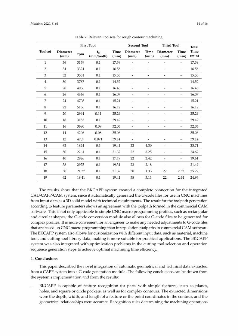
In addition to G-code generation, BKCAPP also provides an algorithm for tool diameter selection in order to minimize the cutting time in rough machining on the basis of dimensional data, including the depth, width, and length of the feature, the minimal dimensions between walls, the minimal dimensions between a wall and island, and the dimensions between two islands. Table 7 indicates the toolsets that can be used for the rough machining of an example contour. The toolsets are different in terms of the tool diameter and number of tools needed from the tool database input for the operation. In the case of an example contour feature, the rough machining can involve toolsets with one, two, or three tools, as shown in Table 6. However, the tool diameter selection algorithm in BKCAPP shows that using one end mill measuring 30 mm for cutting results in a better cutting time, which was proven by simulation in CAM software, giving a total cutting time of 14.52 min.
The results show that the BKCAPP system created a complete connection for the integrated CAD-CAPP-CAM system, since it automatically generated the G-code files for use in CNC machines from input data as a 3D solid model with technical requirements. The result for the toolpath generation according to feature parameters shows an agreement with the toolpath formed in the commercial CAM software. This is not only applicable to simple CNC macro programming profiles, such as rectangular and circular shapes; the G-code conversion module also allows for G-code files to be generated for complex profiles. It is more convenient for an engineer to make any needed adjustments to G-code files that are based on CNC macro programming than interpolation toolpaths in commercial CAM software. The BKCAPP system also allows for customization with different input data, such as material, machine tool, and cutting tool library data, making it more suitable for practical applications. The BKCAPP system was also integrated with optimization problems in the cutting tool selection and operation sequence generation steps to achieve optimal machining time efficiency.
Figure 7. The interface of the G-code generation module.
Machines 2020, 8, 61 13 of 16Machines 2020, 8, x 14 of 16
In addition to G-code generation, BKCAPP also provides an algorithm for tool diameter selectionin order to minimize the cutting time in rough machining on the basis of dimensional data, including thedepth, width, and length of the feature, the minimal dimensions between walls, the minimal dimensionsbetween a wall and island, and the dimensions between two islands. Table 7 indicates the toolsets thatcan be used for the rough machining of an example contour. The toolsets are different in terms of thetool diameter and number of tools needed from the tool database input for the operation. In the case ofan example contour feature, the rough machining can involve toolsets with one, two, or three tools,as shown in Table 6. However, the tool diameter selection algorithm in BKCAPP shows that using oneend mill measuring 30 mm for cutting results in a better cutting time, which was proven by simulationin CAM software, giving a total cutting time of 14.52 min.
Machines 2020, 8, 61 14 of 16
Table 7. Relevant toolsets for rough contour machining.
Toolset
First Tool Second Tool Third Tool TotalTime(min)
Diameter(mm) rpm fz
(mm/tooth)Time(min)
Diameter(mm)
Time(min)
Diameter(mm)
Time(min)
1 36 3139 0.1 17.39 - - - - 17.39
2 34 3324 0.1 16.58 - - - - 16.58
3 32 3531 0.1 15.53 - - - - 15.53
4 30 3767 0.1 14.52 - - - - 14.52
5 28 4036 0.1 16.46 - - - - 16.46
6 26 4346 0.1 16.07 - - - - 16.07
7 24 4708 0.1 15.21 - - - - 15.21
8 22 5136 0.1 16.12 - - - - 16.12
9 20 2944 0.11 25.29 - - - - 25.29
10 18 3183 0.1 29.42 - - - - 29.42
11 16 3680 0.09 32.06 - - - - 32.06
12 14 4206 0.08 35.06 - - - - 35.06
13 12 4907 0.071 39.14 - - - - 39.14
14 62 1824 0.1 19.41 22 4.30 - - 23.71
15 50 2261 0.1 21.37 22 3.25 - - 24.62
16 40 2826 0.1 17.19 22 2.42 - - 19.61
17 38 2975 0.1 19.31 22 2.18 - - 21.49
18 50 21.37 0.1 21.37 38 1.33 22 2.52 25.22
19 62 19.41 0.1 19.41 38 3.11 22 2.44 24.96
The results show that the BKCAPP system created a complete connection for the integratedCAD-CAPP-CAM system, since it automatically generated the G-code files for use in CNC machinesfrom input data as a 3D solid model with technical requirements. The result for the toolpath generationaccording to feature parameters shows an agreement with the toolpath formed in the commercial CAMsoftware. This is not only applicable to simple CNC macro programming profiles, such as rectangularand circular shapes; the G-code conversion module also allows for G-code files to be generated forcomplex profiles. It is more convenient for an engineer to make any needed adjustments to G-code filesthat are based on CNC macro programming than interpolation toolpaths in commercial CAM software.The BKCAPP system also allows for customization with different input data, such as material, machinetool, and cutting tool library data, making it more suitable for practical applications. The BKCAPPsystem was also integrated with optimization problems in the cutting tool selection and operationsequence generation steps to achieve optimal machining time efficiency.
4. Conclusions
This paper described the novel integration of automatic geometrical and technical data extractedfrom a CAPP system into a G-code generation module. The following conclusions can be drawn fromthe system’s implementation and from the results:
- BKCAPP is capable of feature recognition for parts with simple features, such as planes,holes, and square or circle pockets, as well as for complex contours. The extracted dimensionswere the depth, width, and length of a feature or the point coordinates in the contour, and thegeometrical relationships were accurate. Recognition rules determining the machining operations
Machines 2020, 8, 61 15 of 16
for each machining feature on the basis of the extracted dimensions were adequate in a properoperation sequence;
- The G-code generation module using the macro programming method was efficient for 2.5Dmachining features with G-code files directly generated from CAPP data. With parametricprogramming, the toolpaths were concise and simple to follow and edit. This is not usually thecase for toolpaths generated using CAM software with complex manual processes. BKCAPP alsoprovides an algorithm for tool diameter selection to help reduce the machining time, which hasnot been provided in any other CAM software system;
- The G-code generation module can be used as a new G-code cycle for manual programming,can be combined with CAD–CAPP modules to form a completed CAD–CAPP–CNC integrationsystem, or can be used in a CNC machine. In future research, we will focus on G-code generationfor 3D complex curves and machining accuracy in comparison with a CAM output program.
Author Contributions: Conceptualization, T.K.N., L.X.P.; methodology, T.K.N., L.X.P.; validation, T.K.N., L.X.P.,and N.-T.B.; formal analysis, T.K.N., L.X.P., and N.-T.B.; investigation, T.K.N., L.X.P.; writing—Original draftpreparation, T.K.N., L.X.P., and N.-T.B. All authors have read and agreed to the published version of the manuscript.
Funding: This study was conducted with financial support from Hanoi University of Science and Technology(HUST) under project number T2018-PC-027.
Acknowledgments: The School of Mechanical Engineering at HUST is gratefully acknowledged for providingfunding, guidance, and expertise. This work was also supported by the Centennial Shibaura Institute ofTechnology Action for the 100th anniversary of Shibaura Institute of Technology to enter the top ten AsianInstitutes of Technology.
Conflicts of Interest: The authors declare no conflict of interest.
References
1. Bachtiak-Radka, E.; Dudzinska, S.; Grochala, D.; Berczynski, S.; Olszak, W. The influence of CNC millingand ball burnishing on shaping complex 3D surfaces. Surf. Topogr. Metrol. Prop. 2017, 5, 015001. [CrossRef]
2. Narooei, K.D.; Ramli, R. Application of artificial intelligence methods of tool path optimization in CNCmachines: A review. Res. J. Appl. Sci. Eng. Technol. 2014, 8, 746–754. [CrossRef]
3. Scheer, A.W. CIM Computer Integrated Manufacturing: Towards the Factory of the Future; Springer Science andBusiness Media: Berlin, Germany, 2012.
4. Anderberg, S.; Beno, T.; Pejryd, L. CNC machining process planning productivity: A qualitative survey.In Proceedings of the International 3rd Swedish Production Symposium (SPS 2009), Göteborg, Sweden,2–3 December 2009; pp. 228–235.
5. Kundrak, J.; Molnar, V.; Deszpoth, I. Comparative Analysis of Machining Procedures. Machines 2018, 6, 13.[CrossRef]
6. Yu, B.F.; Chen, J.S. Development of an Analyzing and Tuning Methodology for the CNC Parameters Basedon Machining Performance. Appl. Sci. 2020, 10, 2702. [CrossRef]
7. Abas, M.; Salah, B.; Khalid, Q.S.; Hussain, I.; Babar, A.R.; Nawaz, R.; Khan, R.; Saleem, W. ExperimentalInvestigation and Statistical Evaluation of Optimized Cutting Process Parameters and Cutting Conditions toMinimize Cutting Forces and Shape Deviations in Al6026-T9. Materials 2020, 13, 4327. [CrossRef]
8. Solarte-Pardo, B.; Hidalgo, D.; Yeh, S.S. Cutting Insert and Parameter Optimization for Turning Based onArtificial Neural Networks and a Genetic Algorithm. Appl. Sci. 2019, 9, 479. [CrossRef]
9. Kuntoglu, M.; Aslan, A.; Pimenov, D.Y.; Giasin, K.; Mikolajczyk, T.; Sharma, S. Modeling of CuttingParameters and Tool Geometry for Multi-Criteria Optimization of Surface Roughness and Vibration viaResponse Surface Methodology in Turning of AISI 5140 Steel. Materials 2020, 13, 4242. [CrossRef]
10. Xu, X.; Wang, L.; Newman, S.T. Computer-aided process planning: A critical review of recent developmentsand future trends. Int. J. Comput. Integr. Manuf. 2011, 24, 1–31. [CrossRef]
11. Al-Shebeeb, O.; Gopalakrishnan, B. Computer-aided Process Planning Approach for Cost Reductionand Increase in Throughput. In Proceedings of the International Conference on Operations Management(IOEM 2016), Detroit, MI, USA, 23–25 September 2016; pp. 632–644.
12. Yusof, Y.; Kamran, L. Survey on computer-aided process planning. Int. J. Adv. Manuf. Technol. 2014, 75,77–89. [CrossRef]
13. Besharati-Foumani, H.; Lohtander, M.; Varis, J. Intelligent process planning for smart manufacturing systems:A state-of-the-art review. Procedia Manuf. 2019, 38, 156–162. [CrossRef]
14. Asiabanpour, B.; Mokhtar, A.; Hayasi, M.; Kamrani, A.; Nasr, E.A. An overview on five approaches fortranslating cad data into manufacturing information. J. Adv. Manuf. Syst. 2009, 8, 89–114. [CrossRef]
15. Hayasi, M.T.; Asiabanpour, B. Extraction of manufacturing information from design-by-feature solid modelthrough feature recognition. Int. J. Adv. Manuf. Technol. 2009, 44, 1191–1203. [CrossRef]
16. Zhou, X.H.; Qiu, Y.J.; Hua, G.R.; Wang, H.F.; Ruan, X.Y. A feasible approach to the integration of CAD andCAPP. Comput.-Aided Des. 2007, 39, 324–338. [CrossRef]
17. Lau, H.C.W.; Lee, C.K.M.; Jiang, B.; Hui, I.K.; Pun, K.F. Development of a computer-integrated system tosupport CAD to CAPP. Int. J. Adv. Manuf. Technol. 2005, 26, 1032–1042. [CrossRef]
18. Tong, Y.F.; Li, D.B.; Li, C.B.; Yu, M.J. A feature-extraction-based process-planning system. Int. J. Adv.Manuf. Technol. 2008, 38, 1192–1200.
19. Abdelilah, E.; Ahmed, R.; Oussama, J. Optimized-automated choice of cutting tool machining manufacturingfeatures in milling process. In Proceedings of the 11th World Congress on Computational Mechanics(WCCM 2014), Barcelona, Spain, 20–25 July 2014; pp. 747–761.
20. Ouyang, H.B. Intelligent cutting tool selection for milling based on STEP-NC machining features.Appl. Mech. Mater. 2014, 635, 589–593. [CrossRef]
21. Amaitik, S.M.; Kiliç, S.E. An intelligent process planning system for prismatic parts using STEP features.Int. J. Adv. Manuf. Technol. 2007, 31, 978–993. [CrossRef]
22. Manafi, D.; Nategh, M.J.; Parvaz, H. Extracting the manufacturing information of machining features forcomputer-aided process planning systems. J. Eng. Manuf. 2017, 231, 2072–2083. [CrossRef]
23. Hasan, M.A. A Conceptual Framework of Common Variables in CNC Machines Programming for FanucCustom Macros. J. Mater. Sci. Mech. Eng. 2016, 3, 250–253.
24. Joshi, V.; Desai, K.; Raval, H. Machining of Archimedean spiral by parametric programming. Int. J. Mod.Manuf. Technol. 2016, 8, 25–30.
25. Phung, L.X.; Van Tran, D.; Hoang, S.V.; Truong, S.H. Effective method of operation sequence optimization inCAPP based on modified clustering algorithm. J. Adv. Mech. Des. Syst. Manuf. 2017, 11, 1–12. [CrossRef]