USACERL TECHNICAL REPORT FE-93/08 November 1992 Coal Use Technologies US Army Corps AD-A262 952 of Engineers I , 1,, i' 1 t Construction Engineering I I It! Research Laboratories I ! 1151 An Overview of Atmospheric Fluidized Bed Combustion Systems as Applied to Army Scale Central Heat Plants by Janet M. Gutraj Christopher F. Blazek Gary W. Schanche Atmospheric Fluidized Bed Combustion (AFBC) technology involves burning sulfur-containing fuel particles suspended in an air stream. Although AFBC technology typically is applied to new heating plants, it may also be used for retrofit. This report provides planners and design engi- neers an overview of the fuel handling require- ments, combustion characteristics, emissions control, and project economics of AFBC technolo- i '"-T gies as applied to both new and retrofit boilers. APR14 The discussion includes advantages, disadvan- P 1,19 tages, problems, and solutions. Based on this evaluation, AFBC technology is a practical option for both new and retrofit boilers at Army central heat plants. Although AFBC boilers are economically competitive with conventional coal fired boilers and offer greater fuel flexibility, AFBC boilers firing coal are not competitive with oil or gas in the current energy market. 93-07725 Approved for public release; distribution is unlimited.
Transcript
USACERL TECHNICAL REPORT FE-93/08November 1992
Coal Use Technologies
US Army Corps AD-A262 952of Engineers I , 1,, i' 1 tConstruction Engineering I I It!Research Laboratories I ! 1151
An Overview of Atmospheric FluidizedBed Combustion Systems as Applied toArmy Scale Central Heat Plants
byJanet M. GutrajChristopher F. BlazekGary W. Schanche
Atmospheric Fluidized Bed Combustion (AFBC)technology involves burning sulfur-containing fuelparticles suspended in an air stream. AlthoughAFBC technology typically is applied to newheating plants, it may also be used for retrofit.This report provides planners and design engi-neers an overview of the fuel handling require-ments, combustion characteristics, emissionscontrol, and project economics of AFBC technolo- i '"-Tgies as applied to both new and retrofit boilers. APR14The discussion includes advantages, disadvan- P 1,19
tages, problems, and solutions.
Based on this evaluation, AFBC technology is apractical option for both new and retrofit boilers atArmy central heat plants. Although AFBC boilersare economically competitive with conventionalcoal fired boilers and offer greater fuel flexibility,AFBC boilers firing coal are not competitive withoil or gas in the current energy market.
93-07725
Approved for public release; distribution is unlimited.
The contents of this report are not to be used for advertising, publication,or promotional purposes. Citation of trade names does not constitute anofficial endorsement or approval of the use of such commercial products.The findings of this report are not to be construed as an officialDepartment of the Army position, unless so designated by other authorizeddocuments.
DESTROY THIS REPORT WHEN IT IS NO LONGER NEEDED
DO NOT RETURN IT TO THE ORIGINATOR
REPORT DOCUMENTATION PAGE 0Publi rpoooninfg burdenfo 1 t his oldlotio d otormu*wo a dwrnv to &DtfhQ. 1 ntow Pe 'esponie' Clct0 N thr e 1. toS Actattd. "WuA V. n "t o 'A cgpthherng and n ntamnng the dat needed and coTivitng And fevvwrng th*e coli&ctn of efos mAlr,' Sen coors'libe ' 'rV • heg th ke l IM4 O• a ( fp0"W a; e tueh
co4ed~on of trlormiabon w~dtng Suggestions lot rodcng the bu~nW to Washington HeoAtdtm Samrcas 0adodwee koy. Vruow'n c wax0A SAqOt~ F '4ý 1?1 Sf"MDave l-lgh*ay Sude 1204 Arloglon VA,42202 4302 and to It'. oft1-c or MOgetorna a"dI.~ 049 Pp r .Odu Av ' emo i ýVTO4 016 ht..r9 "k ;US
1 AGENCY USE ONLY ,Loeave Biank) RE2 REPORT DATE 3 REPORT 'YPE AND3 D!EAS COVEiRL
r November 1992 1 Final4 TITLE AND SUBTITLE 5 ".,IG NMfiRS
An Overview of Atmospheric Fluidited Bed Combustion Systems as Appliedto Army Scale Central Heat Plants Pt 4A162791
PR AT456. AUTHOR(S) TR DTADIJanet M. Gutraj, Christopher F. Blazek. and Gary W. Schanche WU (0)6
U.S. Army Construction Engineering Research Laboratories (USACERL)PO Box 9W05 TR FE-931tiXChampaign, IL 61826-9X)5
9. SPONSORING/MONITORING AGENCY NAMES) AND ADORESS(ES) 10 SPONSCRNGMON TOR NC
AGENCY RF- PO•I N MSF R
US Army Engineering and Housing Support CenterATTN: CEHSC-FUFort Belvoir, VA 22060-5580
11 SUPPLEMENTARY NOTES
Copies are available from the National Technical Information Service, 5285 "ort Royal Road. Spring-field, VA 22161
12a, OISTRIBUTION/AVAILABILITY STATEMENT '' ,s ON cou
Approved for public release; distribution is unlimited.
13 ABSTRACT (Maxinum 200 words)
Atmospheric Fluidized Bed Cumbustion (AFBC) technology involves burning sulfur-containing fuelparticles suspended in an air stream. Although AFBC technology typically is applied to new heating plants.it may also be used for retrofit. This report provides planners and design engineers an overview (of the fuelhandling requirements. combustion characteristics, emissions control, and project economics of AFBCtechnologies as applied to both new and retrofit boilers. The discussion includes advantages. disadvantages.problems, and solutions.
Based on this evaluation, AFBC technology is a practical option for both new and retrofit boilers atArmy central heat plants. Although AFBC boilers are economically competitive with conventional coalfired boilers and offer greater fuel flexibility. AFBC boilers firing coal are not competitive with oil or gasin the current energy market.
14 SUBJECT TERMS 15 NUMBER OF PAGES
atmospheric fluidized bed combustion 102boilers heating plants 16 PRICE CODE
17. SECURITY CLASSIFICATION 18. SECURITY CLASSiFICATION 19 SECURITY CLASSIFiCATION 20 LIMITATION OF ABSTRACTOF REPORT JOF THIS PAGEI OF ABSTRACT
This study was conducted for the U.S. Army Engineering and Housing Support Center (L SALiSC)under Project No. 4AI62781AT45, "Energy and Energy Cotnserv-atilon'"; T''echnical Area 1), WVtirk I nit (X)O."Coal Use Technologies." The USAEHSC Technical Monitlor "as Bernard S. Wasserniat (ClI-SC .I).
This re-earch was performed by Janeel M. Guiraj and Christopher V. Bla/ek of the Instiautc ot GasTechnology, Chicago. IL. for the Energy and Utility Systems Div)ision (II). lnraqlrut ure Lahoratwr(FL), U.S. Army Construction Engineering Research Labxratones (LSACI:Rl.,. Dr. Da'.id \1ý JoiLhis Chief, CECER-FE and Dr. Michael J. O'Connor is Chief. CECI-R-FL C- an W. SCIhancLhe IN TCarllLeader of the Fuels and Power Systems Team. The technical editor "as Gloria J. Wienke. t SAC: R1,Information Management Office.
COL Daniel Waldo, Jr., is Commander and Director of LSACERL. and Dr. L.R. Shtlfer isTechnical Director.
Accesion For
NTIS CRA&ITDT!C TAB.,
Just•lf: o;
B y ............ ...................... . .Dist; btic: I
AvaiiL•bihty Coces
Avai 1l d I IorDist Special
-D1
CONTENTSPage
SF298 IFOREWORD 2LIST OF FIGURES AND TABLES 5
I INTRODUCTION ...................................................... 9Background 9Objective 9Approach 9Mode of Technology Transfer 9
2 BOILER DESCRIPTIONS ............................. 10Characterization of AFBC Technologies 10Retrofits 14Characterization of Conventional Coal Fired Boilers 17Advantages of AFBC Over Conventional Coal Fired Boilers 20
3 CAPABILITY OF AFBC TECHNOLOGIES .............................. 22Combustion Efficiency/Boiler Efficiency 22Fuel Flexibility 23Emission Characteristics 24Turndown and Load Following 25
5 AFBC MANUFACTURERS ........................................... 35Vendor List 35Description of Vendor Packages 35Summary of AFBC Manufacturers' Designs 41
6 DISCUSSION OF AFBC BOILER INSTALLATIONS ....................... 46AFBC Boilers in the United States 46Bubbling Bed 46CFBC Boiler 48Multiple Bed 54
7 EMISSION STANDARDS ............................................ 58Current Federal Standards 58Current California Standards 58Ability of AFBC Boilers To Meet Emission Standairds 60
9 SUM M AR Y ....................................................... 79
METRIC C)NVERSION TABLE 79
REFERENCES SO
APPENI)IX: AFBC INSTALLATIONS IN IE UNITED STATES 83
GLOSSARY OF TERMS 92
I)ISTRIBUTION
4
FIG URES
Number Page
I Diagram of bubbling fluidized bed combuster (BFBC) I I
2 BFBC illustrating three types of coal feeding I I
3 Diagram of a circulating fluidized bed combustor (CFBC) 13
4 Bed sizing area 15
5 Retrofit involving extended fumance area in oil/gas boiler 16
6 Recommended limits of coal sizing for conventional boilers Is
7 Projected performance of sorbent 26
8 Air nozzles 33
9 Babcock & Wilcox "L'" valve operation 37
10 Combustion Engineering's CFBC system 37
11 Combustion Power Company fines circulating fluid bed boiler 38
12 Foster Wheeler Cyclone design 39
13 Foster Wheeler boiler layout 40
14 Riley Stoker MSCFB boiler design 42
15 Riley Stoker MSCFB boiler layout 42
16 Stone Johnstone boiler 43
17 Wormser's dual bed system 44
18 Wormser's dual bed boiler 44
19 Midwest Solvents Company boiler 47
20 Archer Daniels Midland boiler 50
21 B.F. Goodrich boiler 53
22 Wormser Engineering firing train 55
23 AFBC capital costs vs steam rate 69
24 AFBC capital costs per PPH vs steam rate 70
5
FIGURES (Cont'd)
Number Page
25 AFBC annual operating and maintenance costs 72
26 Range of AFBC capital costs 74
TABLES
1 Combustion Efficiencies of AFBC Boilers
2 Boiler Efficiencies for AFBC Boilers and Conventional Boilers 2-
3 Sulfur Capture Capabilities of AFBC Boilers 24
4 Nitrogen Oxide Levels [or AFBC Boilers 27
5 Turndown and Load Following for AFBC Boilers 27
6 List of AFBC Boiler Manufacturers 36
7 AFBC Boiler Manufacturer Listing 45
8 Midwest Solvents Company Operating Data 49
9 Archer Daniels Midland Operating Data 52
10 B. F. Goodrich Operating Data 54
11 Federal Emission Standards for Boilers 59
12 State of California Particulate Emission Standards 60
13 AFBC Manufacturer's Emissions 61
14 BFBC/CFBC Comparison 64
15 BFBC/CFBC Comparison for 100,000 lb/h Unit 65
16 AFBC Capital Cost Estimates 69
17 AFBC Capital Costs 70
18 AFBC Annual Operating and Maintenance Costs 71
19 Average Auxiliary Power Requirements 72
20 Capital Costs From Other Sources 73
6
TABLES (Cont'd)
Number Page
21 Cost Breakdown for 10,000 lb/h AFBC Plant 74
22 Cost Breakdown for 50,000 lb/h AFBC Plant 75
23 Cost Breakdown for 100,000 lb/h AFBC Plant 76
24 Cost Breakdown for 2(X),000 lb/h AFBC Plant 77
25 Capital Cost Comparison of 150,000 lb/h Boilers 78
26 Comparison of Operating Costs for 150,000 lb/h Boilers 79
7
AN OVERVIEW OF ATMOSPHERIC FLUIDIZED BED COMBUSTION SYSTEMSAS APPLIED TO ARMY SCALE CENTRAL HEAT PLANTS
I INTRODUCTION
Background
Atmospheric Fluidized Bed Combustion (AFBC) technology has the potential to use alternative fuelsources such as coal, wood, or waste, and is able to reduce and control nitrogen oxide (NOx) and sulfurdioxide (SO 2) emissions. This report reviews AFBC technology for possible use in Army boilers in thesize range of 20,000 to 300,000 lb/h steam.*
AFBC involves burning sulfur-containing fuel particles suspended in an air stream, which causesthem to behave like a fluid. The bed of particles is normally only about 10 percent fuel; the remainderis inert materials and sorbent (dolomite or limestone), which is used to capture up to 90 percent of thesulfur. This sorbent is continually injected into the bed while a gravity drain system withdraws spentmaterial and ash particles. Combustion also occurs at relatively low temperatures (14(X) to 15(X) 'F),which maximizes sulfur capture. This low bed temperature also reduces NOx emission while minimizingclinker (a hard mass of fused furnace refuse) formation. Fly ash and spent sorbent are removed from thestack gas by particulate collectors. This technology is very insensitive to the fuel quality, allowing solidswith a widely varying calorific value to be burned. Typically, AFBC Lechnology is applied in new plants,but recent developments of a shallow bed AFBC system by Wormser Engineering. Inc. has shown thatit may also be used as a retrofit technology. The steam produced by AFBC ranges from low-pressureprocess steam to superheated high-pressure steam. AFBC has also been applied to cogeneration. wherehigh-pressure steam drives turbines to generate electricity. Low pressure steam from the steam turbinesis then used for process applications.
Objective
This report provides planners and design engineers an overview of the fuel handling, combustion,emissions control, and project economics of AFBC technologies as applied to Army scale boilers, bothnew and retrofit designed for gas and/or oil.
Approach
Current AFBC boiler manufacturers were contacted to obtain product information, publishedliterature, and a list of AFBC boiler installations. This material was compared and evaluated to determinethe capabilities and drawbacks of AFBC technologies. Detailed information on AFBC boiler installations,including the ability of these boilers to meet emission standards, was also evaluated. The technical andeconomic factors of AFBC boilers were evalutated.
Mode of Technolofy Transfer
It is recommended that the information in this report be transferred as a Technical Note (TN).
"A metric conversion table is on page 79.
9
2 BOILER DESCRIPTIONS
Characterization of AFBC Technologies
Atmospheric fluidized bed boilers consist of a chamber in which fuel is burned "hilc beingsuspended in a gaseous mixture with inert material and sorbent. The sorbent (most commonly liniestolic)reacts with SO2 released during combustion to form a solid sulfate material. The fluidized bed ismaintained at 1400 to 15()0 'F to maximize sulfur capture. This low temperature also redu•ces NOxemission while minimizing clinker formation. Although these characteristics are common to all fluidizedbed boilers, the fuel and solvent feed systems, ash recycle/removal methods, and heat tranrsfer surfla•c vary.depending on the type of AFBC boiler. Three types are discussed below.
Bubbling Bed
Many design options are used with bubbling fluidized bed combustors (BFBCs), including ashrecycle, underbed or in-bed feeding, and staged combustion. Figure 1 shows a diagram of a typicalBFBC. The combustion air enters the bottom of the bed to produce a velocity of 6 to 16 feet per second(ft/s), flows up through an air distributor plate, and passes through the bed containing the solid fuel,limestone, and ash particles. The maximum size of the bed particles is usually 0.25 in. Crushed coal andsorbent are fed to the bed continuously.
Between 40 and 55 percent of the heat released in burning the fuel is transferred to the water andsteam in the tubes surrounding and submerged in the bed. Convective heat transfer surfaces located inthe path of the exiting combustion gases generate additional steam. Flue gas particulates entrained in thecombustion pr.uducts are removed by cyclones, bag filters, or electrostatic precipiators (ESPs). Capturedparticles are sometimes recycled back to the main bed or burned in a separate fluidizcd bed combustorcalled a carbon burnup cell.
Fuel and Sorbent Feed. To achieve high combustion efficier.cy and maximum sorbent use, the lcedsystem must be designed to evenly distribute the fuel and sorbent into the combustor. The three types otfeed systems used in BFBCs---overbed, underbed, and in-bed-are illustrated in Figure 2.
Overbed feed systems supply fuel and/or sorbent to the surface of the fluidized bed by a spreader.screw conveyor, or through a chute by gravity. Overbed spreaders are generally used for larger boilersbecause one feeder can cover a large area. Overbed feed screws or chutes can be used in situations whereit is not critical to spread the fuel evenly over the entire bed surface. Some designs use chutes withattached cones to spread the fuel over a broader range. Almost any fuel can be used in overbed systems.Coal fines do not interfere with the feed. However. fines can become entrained in the exit [!as. resultingin large amounts of unburned carbon in the ash.
Underbed feed systems introduce fuel and/or sorbent into the bed by a pneumatic feeder throughthe bottom of the combustion zone. Carbon losses with this system are less than with an overbed feedbecause the fines are retained longer in the combustion zone. However, pneumatic underhed feeding israrely used, partly due to the complexity and cost of using several injection points to ensure properdistribution.
10
C[-1ME. STI NE
'I,
•.H •T 1,11N
Figure 1. Diagram of bubbling fluidized bed combuster (BFBC).
superhe3ted slearn fs baghouse arm sta
II sýeam
"
overbedspreaderfeeder ashin-bed ... .
lube bank
waterwall
in-bed screw ] plenufeeder as
edmud drum
Scoal rehir,ng ._._ osa
underbed pneumaicofeed system
Figure 2. BFBC illustrating three types of coal feeding.
ii
lwhbed feed systemls enter the sie of (tie bed be-neath tile surface o1 the combhustion /one, Uh'ilfeeder is suitable for feeding fine,, anld is generally used for smialler boilers since fuel enters at oilly onePoinit,
Asti RCeocle/.sh Remov al. Ash collected troni the gas stream in thle con~ectiie boiler section~s anidcyclones is recycled to1 imlpro)ve combustion efficiecyc and capture SO., 'he miiass flmA ratio is dcfiticdas the ratio of- returned ash to fresh coal. B[BCs commonly use rccxcle ratios of 4:!1 orles
Ash is generally rernioed through drain ports in each bed tompannicni. The drain pori fLt11tior(along the sides, in (the corners, or ini thle center) is a vendor preference.
Heat Transfer Surfac.e and Boiler Designs. Watertube, heat traasfer surfaces are located in thetluidi/cd bed to contro dile bed temperature. These t-jnster surfaces are rows of Itube plaLCd \crtikallN.hori/ontally. or sloped. Because sloping promotes erosion due to flowk paittens created by (hie tube,,. tubesare usually placed almost hori~onial, lowever. hori/ontial tubes require' forced circulationl pumpsJI 'AhILIsloped tubes use natural circulation patterns. Mebrneh-i type waterxmalls canl also be, used for bed transfersurfaces. Because tile fuel contacts thie \katertube surfaces, high heat trauisfei rates are obtained anid theoverall heat transfer surface anid boiler volume can be reduced.
After the hot flue gas exits thie bed, it enters the external COnv.ctfion passCs at'xwe die bed, Thissection can be designed as either a firetube or watertube section and can be used for econon0I'ler orfsuperheating purposes.
Particulate Collection '. The fluid;/ed bed boiler must achieve a carbon use of at least 901 percent tobe competitive with a conventional boiler. Comnbustion efficiency can be improved by reý.c'lling ashparticles to the bed. Cyclones are generally used after the boiler ito capture and recycle dfie ash andsorbent. A baghouse or electrostatic precipitator (ESP) is usually used as the finial dust collector.
Circulating Bed
The circulating fluidi/ed bed combustor (CFBC) di~fers\ from the BFBC in that the sotid particlesare entrained in tile fluidi/ing gases and the bed ihickness is not well defined, Most of the entrainedparticles are captured by a cyclone system and reinjected into the combustlor: therefore, ash recycle isinhercnt to CFBCs. A diagram oif a CFBC boiler is shown in Figure 1. CTI3C decsigns usually requiretall combustors with large combustion zone volumes and relatively large cyclone ash collector Nsx sters.
Primary combustion air at 20 to 30 ft!5 is supplied as thle fluidi/ing medium. whlile Necondar\ airis supplied at the videwalis of the conlbusdhionchlanibem.-- Tile combusnion chambe"-r is usually designed asa waterwall. Fromt the combhustor, the flue gases pass through a tranisition pipe into a hot-solids separator.The solids return via a reentry downcorner and may be cooled in an external heat exchanger (ElIEY Theflue gases pass the heating convection surfaces of the boiler and are then cleaned in a baghouse or LSP.
Fuel and Sorbcnt Feeding. A typical feed system for a CFBC would use a screw feeder or rotaryvalve to meter the fuel and sorbent flow. (Designs using a spreader are also in use.) Thec fuel eniters (thecombustor through one or two feeder,-. A CFBC requires fewer feedling poxinits than :i BFBC. A. CII3Cis tolerant of uneven fuel distribution because of the high mixing rates in the combustor. Also, because
I.F. Thomas. R.W. Gregory, and IM Takadyasu. Ainuispherif Fhauidd Bied Bolk'rs for 1nuIrEA Coal Rccae~h(November 1996)
12
A L t
L 4I fi ,'.
Y
Figure 3. Diagram of a circulating fluidized bed combustor (CFBC).
a CFBC is a higher velocity boiler, it can tolerate somewhat larger fuel particles (0.25 to 2.5 in.). Dueto the recirculation scheme of the CFBC, fines do not decrease the combustion efficiency. Coal dryinggenerally is not required for the boiler itself, but may be required for the solids handling equipment.
Heat Transfer Surface and Boiler Design. CFBC designs consist of a vertical combustor that maybe refractory lined, with waterwall heat transfer surfaces in the upper regions, or may be waterwall lined.The cyclone after the combustor is normally refractory lined. although heat transfer surfaces may heincluded in some designs. Individual designs are distinguished primarily by the presence and performanceof the EHE and the hot-solids separation and reinjection techniques.
An FI.. is essentially a rfrctory-lincud box coutltiing an air-distribution grid and an immersedtube bundle designed to cool material from the cyclone before it is returned to the combustor. Fluidizingvelocity is low in the EHE, less than 3 ft/s, while solids density and heat transfer coefficients are high.Little or no combustion takes place in the EHE. One advantage of an EHE is that it can easilycompensate for variations in :ieat absorption rates caused by changes in fuel properties and loadconditions. Heat transfer in the EHE increases when heat absorption in the combustor decreases and viceversa. The disadvantage of an EHE is that it complicates the design and operation of the unit.
Ash Recycle/Ash Removal. Solids recycling is an inherent part of CFBC systems. Most of theentrained solids that leave the combustor are captured by the cyclone and returned to the combustion zone.The recycle ratio for coal-burning CFBC systems is typically 20:1 or greater.
2 J. Makasi auid R. Schwicger, "Fluidized-Red Boilers," Power (May 1987)
13
Ash is removed from the bed to control the amount of solids and to purge the system. Ash maybe removed at the bottom of the combustor, the econoni,,er hopper, the EHE, or the recycle leg t, thecombustor. The hot ash can also be used to preheat feedwater or combustion air, thus increasing theoverall thermal efficiency of the boiler. Once cooled, it is removed by conventionial tnean,.
Solids Separation, Most CFBCs have at least one cyclone to keep the solids cirLulating. Thecyclone may be water- or steam-cooled to reduce the amnount of high temperature, refractot)-minedductwork and to improve thermal efficiency.
A U-beam separator has also been used as a particle collector. It is comprised ofl U-shaped barsinstalled in a staggered array in a horizontal section of the pipe where the gas makes a 90-degree tuniexiting the combustor. As the gas stream decelerates by about 50 percent compared to the combustor shaltvelocity, particles impinge on the bars and fall into a hopper. This method avoids the use of thickrefractory surfaces in a high abrasion environment, such as in a cyclone where velocities are oftenquadrupled. The U-beam section also adds residence time (by reducing the gas stream velocity). whichimproves combustion efficiency. In addition to the U/beams, this design calls for a multicyclone separatorafter the economizer. Solids captured here can be either recycled or extracted. This backup co)llcctor isused to eliminate potential problems resulting from switching from high to low ash coal.'
Multiple Bed
Multiple bed combustion (MBC) takes place in two fluidized beds in succession (two-stagecombustion). Primmy combustion occurs between 1650 and 1750 'F in the lower bed. Secondarycombustion occurs at about 15W0 'F in the upper bed. SO, emission is controlled by injecting sorrbent intothe upper bed. The upper bed also improves combustion efficiency and allows for a compact design.
Crushed and sized coal is normally fed to the lower bed pneumatically. To avoid clogging, the coalmust be dried. Primary air, which serves as the fluidizing medium, is brought into an air plenum thatcontains nozzles to assure uniform air distribution over the bottom of the bed. Combustion gases releasedfrom the lower bed, together with secondary air added through the distribution plate for the upper bed,act as the fluidizing medium in the upper bed. Small unburned particles from the lower bed are burnedin the upper bed. The uniform secondary air distribution results in very efficient combustion.
Flue gases leaving the combustor pass through the convection section, which may be integrated withthe boiler or be arranged as a waste heat boiler. There is no need for fly ash reinjection. Before the gasesare released to the atmosphere, they are cleaned by a baghouse or ESP.
Energy from the boiler is controlled by varying the fluidization air flow, fuel input, and feedwaterflow. A turndown of 3:1 (30 percent of maximum lead) is possible with no subdivision of the bed. A15:1 turndown is possible with intermittent operation. Load following of 15 percent/min can also beachieved. Several existing boilers have been retrofitted into an AFBC boiler by using the multiple beddesign.
Retrofits
AFBC retrofitting may be an attractive alternative for existing boilers. Boiler types that lendthemselves to retrofitting include pulverized coal, cyclone, stoker, oil, and gas. However, not every boiler
SJ. Makasi and R, Schwieger.
14
is suitable for AFBC retrofitting. Much depends on the site and age of the boiler. Sonic importantconlsiderations are:
o Water/steam circulation design
* Furnace bottom to grade clearanceo Air heater type and arrangement
• Boiler support• Type of particulate control device
, Fan capacityo Space available.
The heat output available from a fluidized bed boiler depends on the bed area and the fluidiuingvelocity. Figure 4 presents the approximate bed area and heat release rate needed to provide tie thermaloutput at a given fluidizing velocity. If the required bed area is similar to the existing boiler area. aretrofit may be possible. However, if the existing boiler area is smaller than required, the boiler area willhave to be increased or stacked beds added.
A typical conversion involving extended furnace area in an oil/gas fired boiler is shown in Figure5. Simple circulation systems. such as those found in low-pressure units are best suited for AFBC retrofitsbecause rearranging the heating surfaces is not necessary.
2.2-÷//
2/
2.6-
2.4
2.2
< 1.5
1.4-
0.4-
FLU: DI ZNG VEFIOC"'/fV
Figure 4. Bed sizing area.
15
inlet outlet* Halt of
Ilt superheatPerZnlet - surface
relocated influidized bed
Pendantsuperheater,
Partial-Conv'ectiondivision wallsI superheater
Economizer
Burners , elefo
SupeheatgeneratingSupereat ubesLightoff and
Air- *-unudistribu>or TTTT
plate FudzncLombustion-
-air dampers
Wtrcoledscrew conveyor
Figure 5. Retrofit involving extended furnace area in oil/gas boiler.
16
Air heaters on existing units are usually rotary regenerative units. Air leakage is possible, especiallywith the higher air pressure required for the fluidizauon air. Additionally, forced draft fan pressures ashigh as 40 to 60 in. water column may be required. This pressure is considerably higher than that inmany existing boilers. except cyclone units. Two options are available for retrofits; either replace the fanor add booster fans. The induced draft (ID) fan is usually suitable, but the pressure drop caused by addinga fabric filter may require a larger fan. Particulate control in retrofits is accomplished by a baghouse.
An existing boiler may need additional support, either at the top or bottom, because of the AFBCbed weight. Available space around the existing boiler is an important consideration for the practicalityof an AFBC retrofit. An AFBC needs space for the air plenum under the air distribution plate. On a coalfired boiler, this space is provided by removing the ash hopper. Oil/gas fired boilers may need soimemodifications (ductwork or piping). Additional space is also needed for the baghouse and the drypneumatic bottom ash system. The existing fly ash system can be used, but may need modificationStorage space for sorbent and coal is also required.
Characterization of Conventional Coal Fired Boilers
Conventional coal riced steam generators include stoker fired systems and pulverized coal firedsystems. Stoker fired syst:ms are generally smaller and simpler, with steam production limited to 3(X).(XX)lb/h when coal of widely varying properties is burned. Pulverized coal fired systems are generally larger.steam production rates for these systems are generally greater than 2)00(XX) lb/h.
Fixed Grate Combustors
Underfeed Stokers. The fixed grate, underfeed stoker is usually a horizontal-feed, single retortsystem. Coal is fed from a hopper by a reciprocating ram, or a screw, to a central trough called a retort.As the coal rises in the retort and is subjected to heat from the burning coal above, volatile gases aredistilled off and mixed with air supplied through tuyeres (nozzles) above each side of the retort andthrough the side grates. The volatile mixture bums as it passes upward through the incandescent zone,sustaining ignition of the rising coal. Burning continues as the incoming coal forces the fuel bed to thesides. Combustion is completed by the time the bed reaches the side grates from which ash is discharged.
This stoker is commonly arranged to withdraw coal from a bunker and inject it into the fire bed bymeans of a single screw conveyor enclosed in a tube. Underfeed stokers can be built with various othercoal handling arrangements, but direct feed from a bunker or bin is usual. The screw itsclf is the coalmetering element. Ash is removed by raking the hearth area that surrounds the central coal retort andgrate. Stokers with various mechanical means of ash removal have been built, but are uncommon. Ashremoval by hand becomes a problem in the larger stokers.
Coal for the underfeed stoker must not contain lumps too large to pass through the screw. Figure 6indicates the suitable coal sizes for all types of stoker boilers. Fine coal can be burned efficiently,provided that the stoker air supply has sufficient pressure to pass through a bed of fines. Coal preparationis normally not required other than to screen out oversized lumps. Any low-swelling or nonswelling coal.including lignites of up to 40 percent water content, can be buined successfully. High-swelling coal isunsuitable because it tends to build up a large pile of coke over the retort.
Underfeed stokers can be used with any heat removal device that has heat transfer surfaces abovethe furnace. When correctly operated with suitable coal at reasonable firing rates, underfeed stoker firedcombustors emit little smoke, and only a low concentration of particulates entrained in the flue gas. Underthese conditions pollution control equipment (other than an adequate stack) would not be required, Largeinstallations burning high ash coals may require flue gas cleaning equipment. Cyclones or multicyclonesare usually adequate.
17
90/
CD sZ 70-
/60
<OVERFEED STOKERS j N~~~_ w 40
Lii_j > 30< iiCD 22
LLL.M0 C 10-
6 SPREADER STCKERS
C 2
200 tOO 50403020 16 12 8 4;1, 4 1 2 3,4 i !-•22
US STANDARD ROUND HOLE
SIEVE DESIGNATION-- . SCREEN, in.
Figure 6. Recommended limits of coal sizing for conventional boilers. (R. Schwieger, "lndusinalBoilers-What's Happening Today," Power, February 1977 and February 1978.)
The underfeed stoker is an efficient combustion device, and losses of unburned fuel in the ashshould not exceed 20 percent of the true ash weight. The only auxiliary energy required is clectric prxwerto drive the feed screw and the forced draft fan. These will typically use power equivalent to 0.2 to 0.4percent ef the stoker thermal output.
The underfeed stoker has low capital. maintenance, and operating costs. Maintenance is requiredin periodic replacement of the cast iron sections, and clearing the conveying screw ifit becomes jammed.
Spreader Stoker. The spreader stoker is a device designed to distribute coal into the furnace overthe fire with a uniform, but variable spreading action. This method permits suspension burning of finecoal while the larger and heavier lumps fall onto the grate for combustion on a thin fast-burning bed. Theactual spreading device can be a rotating mechanical thrower, an air-swept spout. or a distributing no,/leusing a tangential or conical air stream to spread the coal on the grate.
Usually mechanical grates are used with a spreader stoker. Mechanical grates tip the ash into ahopper, where it is picked up by a mechanical, hydraulic, or pneumatic conveying system. These stokersare usually equipped with fully mechanized ash disposal systems.
The spreader stoker is particularly suitable for applications where rapid load changes can occur. Thesuspension burning of the fines results in almost immediate ignition and the thin fuel bed can be quicklyburned down should the load he shed. Any kind or rank of coal can be burned, although anthracite maycause some difficulties because of its low volatile content. Because much of the coal hums in suspension.large changes in the particle size grading of the coal can upset the operation of a spreader stoker. Figure6 shows the recommended limits of coal sizing for stokers. Waste fuels such as wood bark or hoggedwood can also be burned.
18
Spreader stokers require a regulated and uniform supply of coal to the spreading dcvice.Accordingly, a spreader stoker usually has a separate coal metenring device that lecds the spreader. Thilsmay be a screw, a rotary feeder, or a belt feeder. Ash handling from a fixed grate fired bN a ,preaderstoker entails raking the ash by hand over fairly long distances, which usually limits tie siue of the boiler.
The spreader stoker can handle almost any type of coal. Low-ash coals are preferred. to reduce theash removal. Coal grading should be as uniform as possible to avoid large vanations in the quantity titcoal burned in suspension.
Because much fine coal is burned in suspension, spreader stokers may have a large carrmocr ofsolids in the flue gas. The particulates carried by the flue gas may include considerable amounts ofunburned fuel. up to 70 percent in some cases, and typically 50) percent. For a coal of 7 percent ash. thismeans that about 2.6 percent of the coal fired is likely to escape with the ash. Cyclones and baghousesor ESPs are typically required for cleanup.
The spreader stoker has very low energy requirements. The grate drive, the spreader drive, and thecombustion air fans are unlikely to total more than 0.5 percent of the thermal input of coal. If a baghouseis required, this figure could increase to 1.5 percent of thermal output. These power input figures do riotinclude that proportion of fan power that is required to overcome gas flow resistance in the toiler.
Operating costs of spreader stokers are low. Routine maintenance is due to the spreader mechanismand grate sections. Spreader stokers are also low in capital costs, simple and easy to operate and maintain.highly efficient, easy to control under varying loads, and tolerant of different types and sies tof coal.Some detailed grate designs are discussed below.
Dump Grate. The dump grate consists of sections for each coal feeder with correspondingsectionalized under-grate air plenums. This allows the fuel and air supply to be interrupted while a sectionof the grate "dumps" ash without disturbing the other sections. Dumping grate stokers tip the ash into apit or hopper, where it is picked up by a conveying system. Coal ash should not exceed 10 percent fordumping grates, unless the heat release rate per unit area of grate surface is reduced by 25 to 30 percent.
Traveling Grates. Mechanical traveling grates act as their own feeders, and hence are provided witha feed bin as an integral part of the stoker. Any kind of mechanical coal conveyor, either continuous ordiscontinuous action, can be used to load coal into the feed bin. Traveling grate stokers consist of anentire grate that moves like an endless belt. Coal on the grate is burned as it is conveyed to the rear ofthe furnace where the remaining ash is dumped. A drag chain conveyor working in water is commonlyused to remove the hot ash. Traveling grates are capable of burning a wide range of coals, from high rankeastern bituminous to lignite or brown coal. Very high swelling bituminous coal may present difficulties.and is the least suitable fuel. The size of the coal has a direct bearing on the boiler efficiency andparticulate emissions.
Traveling grates offer fast response to load swings. Turndowns of 5:1 or greater are possible, butoptimum combustion conditions generally deteriorate at ratios above 3:1. Boilers ranging from about75,(X)O to 400,0(X) lb/h have been the primary market of traveling grate stokers.
Generally, the particulate emissions are low and the solids are very small particle size. Usually acyclone mechanical collector is used to clean the gas.
Oscillating Bar Grates. Oscillating bar grates have a horizontal grate formed from bars that propelthe burning coal along the grate. Coal is fed into the fire bed from the end. This stoker was designedfor moderately-swelling bituminous coals that form a coherent fuel bed.
Side or Bulk Feed Chain or Moving Grate. A chain grate is a type of traveling grate that can befed by gravity from a hopper. An adjustable gate regulates the coal bed thickness. Thc upper surface of
19
the coal is heated and igniued by radiation from a refractory arch over the fuel bed. and from the flameitself. The rate of burning is limited by the rate of ignition. Low rank coals with high water content givemuch lower apparent burUnIg rates than higher rank, low moisture coals. The bed continues to bum.becoming progressively thinner as it moves through the furnace, and combustion continues. At the farend of the grate's travel, the ash falls fromn the chain into an ash pit. This ditlcrs from the chain grateused with the spreader stoker where the chain usually discharges the ash at the tromt (f the boiler.
If pans of the grate surface lbrm structural parts of the chain that moves. the stoker is called a"chain grate." If the grate is •eparate. t-arried by the chain and detachable therefrom, it is called a"moving grate" stoker. The characteristics of both types are similar. The moning grate is usually morccostly to buy and install. but may have somewhat lower maintenance costs.
For chain and moving grate stokers, the coal enters at one end and bums down graduallv as ittraverses the furnace. Any type off coal can be burned on these grates. but dilferent arrangements ()Iignition arches and overfire air may be required for fuels with either very high or very low ',olatilescontent. The stoker responds very slowly to changes in demand. It emits much less solid matter to theflue gas than does any spreader stoker, but it requires a considerably larger grate area for a given outputthan does a moving grate spreader stoker.
Inclined Rotating Grate. This moving grate is similar to the oscillating bar grate, but is set on anangle of 10 to 15 degrees. Movement of the grate bars causes the fuel bed to roll over and over as itmoves along the grate. This type of grate was used 40) to 50 years ago in large boilers to burn highmoisture lignite. This grate system is much more expensive than either spreader or chain grates. and hasno advantage with any normal coal; therefore it is rarely used.
Pulverized Coal Boilers
A pulverized coal (PC) tiring system bums coal particles in a fine spray. A PC combustor can burncoal with an ash content up to 47 percent, provided that the coal is g-'iund to a small enough particle si/c.Fuel required for a PC coal boiler is processed in mills that grind to 2(X) mesh or finer. This coal isentrained into the burners by preheated primary air. The secondary air is preheated. conveyed to theboiler, and distributed at points around and above the burners. Inside the boiler. the coal particles aresubjected to heat and mixed with the preheated air. The fuel vaporizes almost instantly into combustiongases and particles or char. The particles of char contain the sulfur and are quickly oxidized into carbondioxide (CO) and SOq. Proper control of both SO, and NOx requires additional equipment. NOxformation can be reduced by using staged combustion, recirculation of flue gases. water injection, or sonicother means to reduce the combustion temperature. All of these contnrl methods. except stagedcombustion, reduce the efficiency of the boiler. NOx can also be reduced chemically by injectingammonia or urea,. _OY ,:,n he removed in a wet scrujbber bv re: c.ion with ,,lciium carin.ale. Th.
quantity of limestone required by the scrubber varies with the sulfur content of the fuel, the temperatureof the flue gases, and the natural pH of the wetted fly ash/flue gas mixture. An average ratio of 1.4:1 istypical for 90 percent removal.
A properly designed and operated PC boiler can hold carbon efficiency loss to less than (R5 percent.but a traveling grate spreader stoker can do no better than about 4 percent with 50 percent ash reinjection.One penalty for the higher efficiency of the PC fired boiler is the power required to operate thepulverizers. Pollution control costs may also be higher with the PC fired boiler because all fuel is burnedin suspension.
Advantages of AFBC Over Conventional Coal Fired Boilers
A summary of the major claimed advantages of AFBC boilers is presented below. These claims aredescribed briefly here, but many are dealt with quantitatively and in greater detail in Chapters 3 and 4.
20
* By using the high heat transfer rates of in-bed boiler tubes, AFBCs have been claimed to requireless overall heat transfer surface. This should result in smaller boilers than for stoker or pulverized coalunits.
• Operating temperatures are below the fomnation point for thermally induced NOx. Stagedcombustion can also be applied to minimize oxidation of fuel-bound nitrogen.
* The lower combustion temperature avoids the appreciable slagging and fouling associated withPC fired and stoker fired units.
* AFBC boilers can bum various solid fuels and wastes. Usually these units can bum natural gasand fuel oil as backup fuels. This flexibility is attractive because it allows the use of alternative fuels.
e AFBC systems can burn higher sulfur coals without having expensive scrubber systems, and stillmeet air quality standards. This is achieved by the direct contact of combustion gases and sorbent duringthe combustion process in the fluidized bed. The dry solid stabilized waste product sulfate, rather thansulfite, is easily disposed of.
• The fluidizing mechanism, or added turbulence, offers several advantages: less volatilization ofalkali components, reduced chance for hot spots on boiler and shell surfaces, less sensitivity to the quantityand nature of the ash in the fuel, and smaller furnace volume.
21
3 CAPABILITY OF AFBC TECHNOLOGIES
Combustion Efficiency/Boiler Efficiency
Combustion efficiencies (carbon utilization) for AFBC boilers range lrom 701 to 99.5 percent. Theloss in combustion efficiency arises from incomplete comrbustion of fixed carbon (char) and ýolatiles.Higher efficiencies are attained through modifications of the system. This increases both the cormplcxutof the system and the cost. Table I summarizes the measured combustion efficiencies front commcrcialboilers and demonstration units.
Table I
Combustion Efficiencies of AFBC Boilers'
FBC Boiler Design Type of Fuel Combustion EfficiencN. %
BFBC with bituminous - high fines 85-98overbed feeding bituminous - low fines 90-94(no recycle) bituminous - low fines. 94-97
high volatileslignite/subbituminous 97-98anthracite/bituminous 70-85
wash tailings
BFBC with bituminous - high fines 94-95overbed feeding and bituminous - low fines 98-99ash recycle bituminous - low fines. 98-99.5
high volatileslignite/subbituminous 98-99anthracite/bituminous 80-93
wash tailings
BFBC with bituminous 96-98pneumatic underbed bituminous - high volatiles 98-99.5feeding and ashrecycle lignite/subbituminous 98-99.5
Multibed pneumatic coal, peal wood chips 98underbed feed
" Source: I.F. Thomas, R.W. Gregory, and M. Takadyasu.
The combustion efficiency depends on the fuel reactivity, volatile content, and particle siue.Reactive coals such as lignite or subbituminous will burn relatively efficiently without using ash recycle
J F. Thomas, R.W. Gregory, and M. Takadyasu.
22
or underbed feeding. The reactivity of bituminous coals may be sensitive to fines content. Unreacti-efuels such as anthracite may result in low efficiencies. These fuels may burn more efficiently in anunderfeed bubbling boiler with ash recycle or in a CFBC system. Because many uses of AFBC boilersinclude burning, of less efficient solid wastes, many researchers feel that AFBC boilers" efficiencies shouldnot be compacd with conventional boiler,-' efficiencies.
Since the AFBC tecnnology is relatively new, calculating the boiler efficiency of fluidized bedboilers is not as well defined as it is for conventional boilers. In addition, the design conditions can varyfrom one supplier to another and each has its own method for determining performance. Table 2summarizes the boiler efficiencies reported from commercial boilers and demonstration units. The highperformance CFBC boiler's efficiency is comparable to the PC boiler's efficiency.
Fuel Flexibility
AFBC boiler systems as noted have a large degree of fuel flexibility. AFBC boilers can be designedto bum almost any fuel with reasonable efficiency. However, problems due to heat transfer restrictionscan arise when switching fuels. The moisture, volatiles content, and reactivity of fuels play an importantrole in the heat release and temperature distribution within the boiler. When the fuel is switched, the heatrelease may no longer correspond to the designed heat transfer surfaces.
BFBCs using overbed feeding and no ash recycle are limited to firing various grades of coal. oil.gas, and coal mixed with moderate amounts of waste. Most experience is with coals that are stokergrades. Lower grade coals can be used if the size is controlled and the ash removal system has sufficientcapacity. However, lower grade coals yield a lower combustion efficiency. Coals with high fines maybe burned more efficiently with ash recycle and underbed feeding. It is possible to switch between fuelsof various types if the fuels are similar (e.g., bituminous to subbituminous coal). In addition. some BFBCsfire coal mixed with moderate amounts of combustible waste, wood, peat, or other fuel. Designs thatinclude controlled staged combustion and/or flue gas recycle in addition to ash recycle, have the greatestfuel flexibility.
CFBC systems are the most tolerant of different fuels. CFBC systems can fire a wide range of coalsas well as oil, gas, waste mixed with coal, and peat. Staged combustion, flue gas recycle, and externalheat exchanger systems enhance the fuel flexibility. The design known as the multisolids CFBC, whichfeatures large stones in the dense zone and an EHE, can handle a wide variety of fuels. A commercialunit has fired bituminous coal, 45 percent ash coal, anthracite duff, peat. and wood.
Table 2
Boiler Efficiencies for AFBC Boilers andConventional Boilers"
AFBC Boiler Design Boiler Efficiency, %
High efficiency CFBC 89.45Low efficiency CFBC 85.66Bubbling Red 83.49Stoker 87,14Pulvenzed coal 89.19
Source: G.L. Gould and M.W. McComas, "Know How EfficienciesVary Among Fluidlized.Bed Boiler%," Power (January 1987).
23
The multiple bed combustion system has also had success burning different fuels. Successful testshave been completed using coal, peat, and wood chips.
Emission Characteristics
Sulfur Capture Capabilities
Table 3 presents the sulfur capture capabilities of AFBC systems. During combustion of solid fuelscontaining sulfur, the sulfur is oxidized to sulfur dioxide. AFBC boilers remove the sulfur dioxide byadding sorbent (limestone or dolomite) directly to the bed. The principle chemical reactions are discussedin the following paragraphs.
Calcination
If limestone (CaCO 3) is added to the combustion chamber, an endothermic calcination reaction toproduce calcium oxide, or lime (CaO) takes place.
CaCO 3 --- > CaO + CO, [Eq 1'
This reaction proceeds only if the partial pressure of carbon dioxide, determined by the excess air level,is less than the equilibrium carbon dioxide partial pressure. which is itself dependent on the bedtemperature. The reaction takes place in the required excess air level at about 15(M to 1750 'F. The rateand extent of calcination is governed by the amount that the equilibrium temperature is exceeded.
If dolomite (CaCO3oMgCO 3) is used, the reaction is more complex. The first step is thermal
decomposition to form a mixture of calcium and magnesium carbonate, which occurs at bed temperatures
Table 3
Sulfur Capture Capabilities of AFBC Boilers*
AFBC Boiler Design % SO 2 Capture Calcium/Sulfur Ratio Notes
BFBC with overhed 60 3.0feeding no ash recycle
BFBC wth overbed 70 .7-2.5 low finesfeeding and ash recycle 70 2.5-3.0 high fines
90 2.8-5,0
BFBC with pneumatic 70 1.8-2.5underbed feeding no 90 3.0ash recycle
BFBC with pneumatic 70 1.5-1.8underbed feeding and 90 2.0-3.0ash recycle
CFBC 90 1.5-2.095 3.0
"Source: J.F. Thomas. R.W. Gregory, and M. Takadyasu.
24
above II(X) 'F. Any magnesium carbonate produced is rapidly calcined, in all fluidizcd cornbusior
conditions, to produce a half-calcined dolomite.
CaCO3 + MgCO 3 --->CaCOI + MgO +O2 [Eq 21
For an atmospheric combustor. further calcination of the calcium carbonate component will take placeaccording to the reaction in Equation 1.
Sulphation
The lime (CaO) generated by calcination of the sorbent reacts with the SO, in the presence ofoxygen to form calcium sulphate.
CaO + SO, + 1/20 2 ---> CaSO4 IEq 31
In the case of fully or half-calcined dolomite, the magnesia (MgO) produced is inert to SO,. It is onlythe calcium component that reacts with SO 2. Therefore, the system needs more dolomite than limestoneto capture a comparable amount of sulfur, Sulfur dioxide can also react directly with calcium cartonate(CaC0 3) present in uncalcined or partially calcined sorbents, according to:
CaCO 3 + SO + 1/2 02---> CaSO 4 + CO2 IEq 41
Sorbent must be added continuously, the spent sorbent must be removed continuously to preventaccumulation in the bed. The method of removal is either by direct elutnation (entrainment in the exhaustgas stream) from the bed if a small enough particle size is used (< 200 microns), or by means of overflowand recycling for larger particle sizes (< 500 microns).
Based on the stoichiometry of the sulphation reaction, the theoretical additive feed rate is one moleof calcium oxide to each mole of sulfur in the coal, or a calcium to sulfur (Ca/S) mole ratio of 1. Thiscorresponds to 3.12 lb limestone or 5.75 lb dolomite per each pound of sulfur in the coal. It is impossibleto achieve total desulfurization because the reaction product CaSO4 blocks the sorbent's pores and reducesits reactivity. Figure 7 shows a typical plot of sulfur retention and the degree of sulphation as a functionof Ca/S ratio. At the theoretical Ca/S ratio, about 30 percent reduction in SO2 emission is achieved. For75 to 90 percent sulfur retention, the typical requirement for emission standards, a Ca/S ratio between 3and 5 must be used. For fuels with a high sulfur content, the sorbent will be a significant proportion ofthe feedstock.
Nitrous Oxide Control
Measured NOx emission levels of various AFBC designs are given in Table 4. In most cases,AFBC systems can burn typical coals and stay well below the NOx emission limits,
During combustion, NOx can originate from the oxidation of atmospheric nitrogen (thcrmaloxidation) or from the oxidation of the fuel nitrogen. Thermal NOx emissions increase with temperature.At the low operating temperatures of fluidized bed combustors, NOx formation is predominantly causedby oxidation of the fuel nitrogen with less than 5 nercent of the NOx produced by thermal oxidation.
Turndown and Load Following
Turndown and load following capabilities are summarized in Table 5. The capabilities of CFBCofilers are generally better than BFBCs, but turndown and load following are dependent on the specific
AFBC design.
25
8 .--. t- ..- i,
• -l'. /7
-"7 //
.1 7-
/
Figure 7. Projected performance of sorbent.
In a CFBC, as thc firing rate decreases, the combustor temperature tends to decline. T1his tcndenicyis corrected by the control system that decreases the flow of cooled solids fronm the recyclc loop, iHeatis absorbed in three sections of the boiler system: the upper section of the combustor in ,aterwallsurfaces, the recycle heat exchanger. and the convective surface downstream of the co•nbustor/rccyclc sub-system. Heat absorption in the combustor and in the gas backpass tend to decline in rough proportion tothe firing rate. The heat absorption in the recycle heat exchanger decreases more rapidly than the firingrate. This rapid decrease occurs because the solids flow is reduced in response to the need t) maintaina constant combustor temperature. Consequently. there is a shift of heat duty toward the combustor andbypass as the load is reduced.
Turndown in a BFBC typically requires a decline in bed temperature with load. The superticater isnormally located in the bed along with a major portion of the evaporative surface. The bed provides auniformly high heat transfer rate for efficient surface utiliiation. As the load is reduced. the bedtemperature is allowed to decline to a minimum temperature of 15(X) 'TF. Zoned bed operation pernitsa wide turndown range, such as 8 to 1. A turndown of 4 to I with a three-zoned bed is common. As thebed temperature reaches the lower limit, a portion of the bed is slumped by closing the fluidiuing airdamper. The fuel is restricted to the remainder of the active bed, Overall AFBC systems arc noted tohave slow load responuse, but some designs with higher response rates compare favorably withconventional boilers.:
¶J.R. Com'parato. "The Thermodynamics and System Design of FBC Boilcrs." Fluidized Red Boders Design adM Apphu alon(Pergamon Press, 1984).
26
Table 4
Nitrogen Oxide Levels for AFBC Boilers'
AFBC System Design NOx Emissions (lb/1M8tu
BFBC with ash recycle 0 13 0.40underbed feeding
BFBC with ash recycle 0.28 - 0.60overred feeding
BFBC with staged 0.17 - 0.30combustion and ash recycle
overbed feeding
CFBC 0.24 -0.42
CFBC with staged combustion 0.10 -0.30
* Bituminous coal feed with I to 2 percent fuel nitrogen. Source:
J.F. Thomas, R.W. Gregory, and M. Takadyasu.
Table 5
Turndown and Load Following for AFBC Boilers'
Boiler Design Turndown (%) Load Foalowing (%/min)
BFBC 65-40 velocity control 3-7>40 by bed slumping or
on/off operation
CFBC without EFE 33-25 4-10
CFBC with EHE 25-13 5-20
Source: I.F. Thomas. R.W. Gregory, and M. Takadyasu.
27
4 DRAWBACKS OF AFBC TECHNOLOGIES
Combustion Limitations
One shortcoming of the AFBC systems is the poor combustion efficiency compared to that of theconventional coal fired boilers. AFBC boilers have a low combustion temperature and short freeboardresidence time compared to stoker and pulverized boilers. The flue gas from a fluidized bed contains ahigh concentration of coal fines and combustibles. If the heating value of the coal fines is lost, the boilerwill have a poor combustion efficiency. This is especially true for small boilers. Possible solutions tothis problem must either improve the combustion rate of these particles or increase the residence time inthe combustion zone. The following paragraphs will highlight some options to improve the combustionefficiency.
A carbon burnup cell (CBC) uses a separate fluidized bed operated at a much lower fluidizationvelocity and higher temperature to bum the fly ash collected from the main fluidized bed. A delicatebalance is required for both the main bed and CBC to be operated in sequence. If the main bed isoperated as an efficient combustor, the CBC will not have enough fuel. Due to the high combustiontemperature in the CBC. the calcium sulfate concentrated in the sulfated sorbent fines can decompose tosulfur dioxide. The high temperature in the CBC may also convert more fuel nitrogen into nitrogenoxides.
Fly ash collected in the primary dust collection system can be reintroduced into the boiler toimprove combustion efficiency, for either overbed or underbed feeding. The efficiency for overbedfeeding is less than that for underbed feeding over the recycle ratios tested. Recycle may not beadvantageous when using reactive coals, but it can greatly improve combustion efficiency of less reactivefuels.
The success of ash recycie requires sufficient temperature. adequate residence time, and goodmixing. In some of the conventional fluidized bed boilers, the freeboard is designed for heat extraction.The reinjected fly ash is barely heated by the fluidized bed before being elutriated into the freeboard.Shortly after, it is collected by the dust collection system. This can form a closed loop of fly ashcirculating through the fluidized bed, freeboard, and dust collection and reinjection systems. In additionto causing a high dust loading, distorted in-bed fluidization, erosion of boiler components, and blindingof the bag filter, fly ash reinjection is not beneficial unless the freeboard temperature is high enough tomaintain some degree of fly ash combustion. Fly ash reinjection has two desirable effects: the renewalof fresh sorbent surface for additional sulfur retention, and the promotion of nitrogen oxide reduction bythe carbon-rich fly ash particles.6
Effort has focused on feed methods to increase the length of time particles stay in the combustionzone. An overbed feed system can feed solid fuels over an area of about 100 sq ft from a single feedpoint. The overbed spreader is intended to distribute coal to the top of the bubbling bed such that thenatural mixing of the bed will result in even combustion. Some particles are carried upward by thefluidization gases. Highly reactive particles may bum up in the freeboard zone, but for less reactive coals.this feed system often requires double screened coal to remove the finer particles that would be carriedout of the combustor and cause low combustion efficiencies. Pneumatic underbed feeding can result inmore uniform fuel distribution and higher combustion efficiency. This system requires only singlescreening to control the maximum size. Because fuel is introduced at the bttom of the combustor, fineparticles have more time to burn before being carried off. This system is more complicated and moreexpensive than the overbed feeding method. In-bed feeding is a compromise between overbed and
J-Y Shang, "An Overview of Fluidized-Bed Combustion Boilers." Fluidized Bed Boiler: Design and Applicaton (PergamonPress, 1984).
28
underbed feeding and introduces fuels into the bed zone through one or more feeders in the sidewalls.This method might not be suitable in large BFBCs because the fuel cannot be distributed evenly enoughby the natural mixing of the bed. and clinkering may occur. For smaller beds, in-bed feeding avoids thecomplexities of underbed feeding while still giving the fine particles time to burn before leaving thecombustion zone.
Underbed pneumatic feeding improves combustion efficiency from about 87 or 88 percent to 92percent for a bituminous coal when ash recycle is not used and when the coal consists of about 20 percentfines. Tests done with 7 percent fines show no substantial improvement by using underbed feeding. Alsolittle advantage is gained by using underbed feeding for very reactive feeds because the fuel reacts wellusing overbed feeding.7
The efficiency of fluidized bed boilers is generally lower than for conventional boilers, except forthe highest efficiency CFBC boilers. Some losses and gains associated with the fluidized bed boiler arediscussed below.
Heat is absorbed when the moisture in the sorbent is converted to vapor. The actual loss dependson the amount of sorbent used to meet the necessary sulfur removal level. For a Ca/S molar ratio of 1.5,the loss is 0.06 percent, but the loss increases to 0.10 percent if the molar ratio is raised to 2.5.
Energy is also required to convert the calcium carbonate and magnesium carbonate in the sorbentto calcium oxide and magnesium oxide. The heat of reaction for the calcination of calcium carbonate isfrequently listed as 787 Btu/lb of material. For magnesium carbonate, 509 Btu/lb is frequently listed. Byusing consistent heats of reaction, the calcination losses will be directly dependent on the Ca/S ratio. Aratio of 1.5 gives a calcination loss of about 1 percent while a ratio of 2.5 increases the loss to 1.7 percent.
Heat is produced in the reaction of SO, and calcium oxide to produce calcium sulfate. The heat ofreaction is about 65 11 Btu/Ib of sulfur. Sulphation gain is directly proportional to the amount of S0 2
removed.
Heat is lost due to heating of the e)-cess air. This loss depends on the quality of the fuel and theexit gas temperature. The loss is slightly higher for the CFBC boiler since additional air is required forthe calcination reactions and carbon dioxide is liberated during this reaction. Sensible heat is lost withthe boiler ash (bottom ash and flyash). Losses can be reduced if heat in the bed ash is recovered.
Radiation and convection losses show wide variations. Actual loss for a unit depends on the amountof refractory or insulation and the method of cooling.!
Fuel Limitations
An AFBC boiler can be designed to bum almost any fuel; however, once the design is fixed, onlya limited range of fuels can be burned without adversely affecting boiler performance.
A BFBC usually is built with a fixed in-bed surface area; however, this can be varied somewhat bydropping the bed height. Because of the different characteristics of fuels, the fixed arrangement of heatingsurfaces does not always efficiently remove the heat. For example. fuels with high volatiles and moisturecontent require no in-bed cooling, but hard coal requires much more in-bed cooling surface to prevent hotspots.
SJF. Thomas. R.W. Gregory. and M. Takadyasu.G.L, Gould and M.W. McComas.
29
CFCBs have large and well mixed combustion zones with ash recycles of 20:1 or more. Becauseof the design of the combustion zone in a CFBC, it is better able than a BFBC to burn varying lucls.
Ash recycle helps to improve the combustion efficiency fbr less reactive fuels in BFBCs. CFBCsystems can use an external heat exchanger that controls cooling of the recycle ash. This helps broadenthe fuel choice because by controlling the temperature of part or all of the solids that are recirculatcd. thecombustor temperature can also be controlled. Staged combustion and flue gas recycle can also helpcontrol combustion, which can also broaden the fuel choice.
Often, it is not the boiler itself but the handling system that limits the tiultifuel capacity. The fuelhandling system must be designed for the fuels that will be used. If the properties of the fuels vary. thefuel handling systems must be able to handle the variations. This may require multiple feeding systems.Also, if oil or gas capability is required, special burners or nozzle designs are required.
Emission Problems
AFBC boilers capture SO2 by using sorbent as a bed material. Presently. AFBC systems can meetvery stringent S02 emission standards. Most of the concern with S02 removal is the large amount ofsorbent consumed.
The Ca/S ratio in a BFBC is usually 2,5:5 and the Ca/S ratio for CFBC is 1.5:2.5. Typically, theCa/S ratio used in AFBC boilers is 2:1 Reducing the sorbent requirements is important because the costof buying and disposing of sorbent may be a significant portion of the overall operating costs.
Low sorbent/calcium use may be due to inadequate contact time for the solid-gas mixture in thefluidized bed, and the formation of a diffusion-resisting calcium sulfate crust that deters the diffusion ofsulfur dioxide into the interior of the calcined sorbent. The solution to these problems is to increase thecontact time between the sorbent and sulfur dioxide and to enhance the sorbcnt's sulfur retentionproperties.
Pretreating limestone-based sulfur sorbents to open the pores for sulfur dioxide diffusion can bedone by precalcination. Treating the sorbents with carbon dioxide can also control the pore size.9
To increase the residence time of the solids, underbed and in-bed feed methods combined with ashrecycle have been used. The improvement in sulfur capture due to underbed feeding depends on thepresence of sufficient feedpoints to achieve good distribution. CFBC systems inherently have a highdegree of ash recycling and solids-gas contact throughout the combustion zone and therefore have bettersorbent utilization than BFBC systems.
The bed temperature is an important parameter in controlling the sulfur retention. The optimaltemperature is about 1400 to 1500 'F. This temperature restriction can affect turndown, load following.and combustion efficiency. Other parameters that influence sulfur capture include bed depth, fluidizationvelocity, freeboard conditions. sorbent type, and particle size distribution.
Disposing of spent sorbent from AFBCs car, pose problems. Under the Resource Conservation andRecovery Act (RCRA), solid wastes from AFBCs can be classified hazardous and may require registrationand special disposal. These requirements can affect AFBC costs, and various options for disposal shouldbe considered. Presently, the wastes are disposed of in sanitary landfills. Potential environmental
" J-Y. Shang.
30
concerns are the p1t and the high concentration of calcium, sulfate. and total dissolved solids in tieleachates. which are above drinking water standards in some cases.'
AFBCs generally achieve NOx emission levels lower than conventional c.mbusihon lechlologie,and more stringent NOx regulations may require careful design of future boilerN. AFBC hoilcrs usuallyoperate with combustion temperatures below 1650 TF and little NOx is formed Irorn nitrogen in thecombustion air. Poorly distributed coal fines or reactive fuel may cause hot spots in the bed. Thcreore.a design that promotes adequate mixing and even distribution of the teed is necessar). CFKCs have large.well mixed combustion zones with high ash recycle rates: therefore hot spots arc not a problem.
Staged combustion has been used to minimi/e NOx formation by introducing secondary air abmethe bed. The reactions that occur because of the staged combustion scheme are:
NOx + C ---> N, + CO Eq 5:
NOx + CO ---> Nx + CO, tEq 01
Carbon monoxide (CO) emission limits may be very strict in some regioMs. To keep the NOxemissions low, the oxygen is kept low; and as the oxygen supply is limiled, more CO is formned COemissions are met under the current regulations. but may pose problems in the future.
Operating Problems
Solids Handling
The major mechanical problems of AFBCs generally are due to the fuel and sorbent fced systems.A reliable feed system capable of distributing the material equally across the bed is vital to the furtherdevelopment of large scale AFBC systems.
Although underbed feed systems provide a longer residence time for the solid particles than overbcdfeeding, and therefore better carbon and sorbent utilization, a major limitation to underbed systems is therequired number of feed points (one feed point for every 9 sq ft). Pneumatic underbed systems havespecial feeders that transfer the coal and/or sorbent from storage hoppers into pneumatic feed lines. Atsome point, the transported material is split into smaller streams before injection into the BFBC.
Erosion and plugging are the main problems of feed systems. Erosion is especially prominent inthe tube bends, elbows, junctions, and flow splitters and any other points where flow disturbances causethe particles to impinge on a surface. Plugging usually occurs where there is a restriction or substantialchange in the flow path.
Erosion can be reduced by limiting flow disturbances in straight tube runs and by using hardmaterials such as ceramics to protect elbows, bends, and splitters. Designs that allow the feed materialto form a layer on the erosion-prone surfaces have shown promise.
Plugging problems can be lessened by controlling the combination of fines and moisture and byeliminating oversized feed particles. Coal moisture should be limited to less than 5 percent. Oversi/edparticles will not move through the system easily and will lodge or collect at certain points. Nonuniformflow of particles in the lines may also cause a blockage to fonn. The physical properties of the fuel and
R.P. Knshman and K.O. Johnsson. International Energy Technology Assessnent-Amw.ophwrw fluded Bed Condrnmhion.
ORNL/TM-8033 (Oak Ridge Nanonal Laboratonrs. April 1982).
31
sorbent (moisture content, lines fraction, erosiveness, tendency to bridge or fomi blockages) must heknown to ensure proper design of the feeding system.
The major concern in overbed feeding is the excessive carryover of unhbumed coal. Fines can escapeand bum in the freeboard above the fluidized bed, allowing most of the resulting SO, to escape. Coalfines must be reduced to ensure proper combustion.
Load Following and Control
Conventional solid fuel boilers have inherently better turndown and load following characteristicsthan AFBC systems. When a load reduction is required in a PC boiler, the fuel feed rate and air rate arereduced to the demand level. In an AFBC btxiler, this reduction in load must be achieved at a nearlyconstant temperature to maintain high combustion efficiency and SO, removal. Maintaining thetemperature is difficult becauso of the heat transfer characteristics of the fluidized bed and the tube matrixin the bed.
Turndown in a BFBC can be achieved by partial bed slumping, in which segments of the fluid bedcan be defluidized to reduce the load at constant temperature. This almost completely slops heat transferto the tube bank in this bed section. There may be a substantial delay when increasing load andtemperature as a section is put back into operation.
Turndown can also be achieved by reducing the fluidiiing gas velocity so that the in-bed heattransfer area is decreased. The bed ione shrinks and uncovers the uppermost bed tubes as the velocityis lowered. Bed material discharge may also be used to reduce bed height, leaving the upper in-bed tubesexposed to the freeboard. These techniques have been used to turn down to -hout 40 percent load.
The rate of tumdown is generally slower for BFBCs than for conventional solid fuel bhoilers.Turndown rates as high as 7 percent/min arc possible when bed slumping is not used and rates of 3percent/min are possible when slumping is used. CFBC systems with external heat exchangers mayachieve a 15 to 20 percent/min turndown while those without may only achieve a 4 percent/minturndown." Most CFBC boilers can accept turndown to 33 to 25 percent of full load, although valuesdown to 12 percent have been repx)rted.
Air Fluidi:ution
In most cases, poor bed fluidization is due to the presence of oversi/e inert particles or because ofan air distribution problem. Oversize particles can be introduced as feed or can be generated by ashagglomeration. Improper air distribution is usually caused by poor design of the distributor system or bya material failure or blockage.
Some faulty air distributors were built in the past. Some of the problems included overheating, poorair nozzle design, and insufficient pressure drop across the distributor assembly, which caused unstableair flow or channeling of air through a small portion of the distributor. Due to previous experience,current designs usually feature well protected (usually water cooled) distributor plates that cause littledifficulty. Figure 8 shows various types of air noilles.
Oversized particles may be reduced by screening the fuel. Particle agglomeration is usually causedby hot zones in the bed and can be avoided by proper AFBC design and careful operating procedures.
J.F Thmrnas. R.W. Grrcg•r. and M Takadyasu.
32
Startup Time
The startup times of AFBC boilers may be longer than for conventional systems. BFBCs require3 to 8 hours and CFBCs require over 8 hours."' The startup fime depends on the amount ()f bed naterinaand refractory to heat up without causing thermal shock.
Erosion/Corrosion
Erosion and corrosion of construction materials havc caused serious problems with AFBC boilersystems, primarily due to the presence of solids moving at relatively high velocities, the high temperatures.and corrosive combustor environments.
Oxidation and sulfidation corrosion occur when metal sulfides in or on the surface of an alloyaccelerate the oxidation of the component. In extreme cases, the corrosion attack can produce holesthrough the tube and significantly degrade tube life. The effects of oxidation and sulfidation are often notreadily apparent. Oxidation and sulfidation attack is enhanced by a low concentration of oxygen in thebed (i.e., partial pressure of about 10 to 12 atmospheres) and may occur on the coal feed points, in-bedheat exchanger, water wall and freeboard heat exchanger, in-bed support structure, uncooled tube supports,and thermocouple assemblies.
Erosion of in-bed components is caused by solid particles moving in the bed. Properties of theimpacting particles, the bed material, and the flow characteristics have a pronounced effect on crosion.Much of the erosion is also believed to be the result of excessively large bubbles caused by poor airdistribution.
TEA;V- BA;; OuEE.E CAP
-J•JJ ) l--"2) t'-
-tAIR AIR Ai;
TuYE(RE
NUT a BOLT
GRID PLATE
AIR AIR
AIR
Figure 8. Air nozzles.
.iF. Thorm&s. R.W. Gregory. and M. Takadyasu.
33
The erosion problems outside the combustor are mainly due to the solids hanwdling equipment. Boththe feed lines and valves are subject to erosive wear. When erosion problems are found, the air llmv, c.abe redirected by inserting a fin or wing. Also, the affected sections can be covered with rcraclory. Thein-bed tubes can be replaced with thicker walled tubes. fined or studded tubes. or a tube made ol dillerentmetal. Metal sprays may also be used to protect the sections.
To avoid corrosion and erosion, the design of AFBC should minimi/e the impingement olparticulate material on component surfaces and permit easy replacement of problem pans. Also. the useof hard metals, coatings, and ceramics should be investigated to reduce material loss. Iron-based lerrilicalloys with high chromium content, austenitic stainless steels, nickel based alloys, and cobalt baed allo)shave been used for in-bed tubes. The recommended material for the water cooled membrane walls ipercent chromium and 50 percent molybdenum steel. This alloy is capable o ',A iuhstanding the corrosi%,eenvironment of the bed and the thernal stresses associated with startup and shutdown over a 20-Neardesign life. Support structures, tube hangers, and other uncooled comp(,eni,( of the combustir \killexperience temperatures almost as high as the fuel temperature. High-chromium alloys are recoMmmcndedfor this application. Hard-faced coatings on carbon or alloy steels can be used to reduce wear in solidsfeed lines.
Fluidied bed industrial .boilers that use water tubes and low temperature (abotut 6(X) FI do notpresent serious material problems. These units are usually small and do not have claborate supportstructures. The uncooled structures in these units are designed to withstand the bed temperatures.
Cogeneration AFBC systems may have serious materials problems. In these systems. steam isheated in a closed cycle to about 15(W 'F and is then expanded through a gas turbine hor elctricgeneration. About 25 percent of the energy is convened to electricity, while ,0 percent (of the remainingenergy is used as process heat. Tube metal temperatures can exceed 1200 `F and the perfiormance ofpresently recommended alloys is questionable. 3
'' R.P. Krishman and K() Juhnsson.
34
5 AFBC MANUFACTURERS
Vendor List
This section discusses the manufacturers of AFBC boilers in the United States. Table 6 list,; thenames and addresses of AFBC manufacturers. The discussion below highlights the main design featuresof each of the AFBC boiler manufacturers' products and indicates the extent to which the company hasbeen and is involved in AFBC technology.
Description of Vendor Packages
Babcock & Wilcox (B&W)
To date B&W has installed four BFBC boilers. They have also installed or plan to install nineCFBCs. B&W recently entered the CFBC market after purchasing the technical knowledge from StudsvikEnergiteknik, Sweden. Their CFBC boiler does not have an EHE but does have a U-beam separator. Theseparator returns the solids through individual stand pipes to the bottom of the combustor. The largestfraction, from the primary separator, is recycled to the bed at a rate controlled by an L-valve. Figure 9shows the principle of the L-valve operation. A small amount of air injected slightly upstream of theelbow partially fluidizes or "aerates" a local zone within it, thus permitting flow of the recycled solids ata rate proportional to the degree of aeration, or modulation of the flow.
Combustion Engineering (CE) Power Systems
CE's main effort in AFBC technology is in developing the CFBC (Figure 10). The solids arcseparated from the flue gas by one or more cyclones and continuously returned to the combustor by anonmechanical valve. Optionally, a controlled amount of solids from the cyclone(s) can be passed throughan EHE and then to the combustor. CE's boilers are based on Lurgi technology and have been improvedby their own boiler expertise.
Combustion Power Company (CPC)
CPC describes their AFBC boiler as a "fines" circulating fluidized bed boiler (Figure 11). It is ahybrid design in which the lower bubbling bed section is coupled with an upper zone that has highmaterial circulation rates. This combination allows good mixing and residence times and high sorbentutilization rates afforded by the circulation features.
Dedert has mainly been involved with small BFBC boilers (20,000 lb/h steam max). Presently, withthe lower cost of fuel and the influx of more companies in the fluidized bed boiler market, Dedert is notactively pursuing the AFBC technology.
Energy Products of Idaho (EPI)
Most of the systems built by EPI have been in the range of 10,000 to 40,(XX) lb/h steam, but theyoffer a BFBC as large as 300.0(X) lb/h. They are working on a retrofit for Northern States PowerCompany at the French Island Power Plant in LaCrosse, Wisconsin. The project entails the design.manufacture, installation, and startup of the retrofit of an existing 150,000 lb/h boiler. The boiler willproduce steam at 450 psi and 750 'F to drive a 15 megawatts electrical (MWe) turbine generator. Theconversion includes the replacement of the boiler grate with a BFBC unit complete with in-bed sur aces.A new economizer and air heater will be added.
35
Table 6
List of AFBC Boiler Manufacturers
Babcock & Wilcox Co. CE Power Systems
20 S. Van Buren Ave. IN(X) Prospect Hill Rd.
Barberton, OH 44203 Windsor, CT 06095
Robert J. Johns Jeff A. Quinwo
(216) 860-2310 (203) 324-4744
Combustion Power Co., Inc. Dederl Corp.
1020 Marsh. Suite 100 Thermal Processes Division
Menlo Park, CA 94025 2(XX) Governors Dr.
Michael O'Hagan Olympia Fields.IL 60461
(415) 324-4744 J.L. Burghard(312) 747-70(X)
Energy Products of Idaho Energy Resources Co., Inc.
4006 Industrial Ave. One Alewife Place
Coeur d'Alene. ID 83814 Cambridge, MA 02140
Brian Meckel (617) 661-3111
(208) 765-1611
Fluidyne Engineering Corp. Foster Wheeler Energy Corp.
3900 Olson Memorial Hwy. 110 S. Orange Ave.
Minneapolis, MN 55422 Livingston, NJ 07039
M, Carroll Robert L. Gamble
(612) 544-2721 (201) 533-3210
Keeler/Dorr-Oliver Power Recovery Systems Inc.
238 West St. 181 Ringe Ave. Extension
Williamsport, PA 17701 Cambridge, MA 02140
Chris Lombardi Peter Vanderschans
(717) 326-3361 (617) 576-1900
Pyropower Corp. Riley Stoker Corp.
P.O. Box 85480 9 Neponset St.
San Diego, CA 92138 Worcester, MA 01606
Jayne A. Gudmundsson Bob Lisauskas
(619) 458-3081 (617) 792-4800
Stone Johnston Corp. Sulzer Bros., Inc.
300 Pine St. 200 Park Avenue
Ferrysburg, M: 4909 New York, NY 10166
Bob Shedd Walter Gadient
(616) 842-5050 (212) 949-0999
Wormser Engineering, Inc. York-Shipley Inc.
67 S. Bedford St. P.O. Box 349
West Lobby, 4th Floor York. PA 17403
Burlington, MA 01803,5129 Martin Gilligan
Richard Sadowski (717) 755-1081
(617) 273-44(X)i
36
Particle Storage
Standpippe
Control Valve
ýAercatlon Tap
Figure 9. Babcock & Wilcox IV' valve operation.
Iu ! u k i i --- S.-onk bw.1IýIIn
( If
7--
RECYCLECYCLONE
POWER BOILER
STEAMOUTLET I SUPERHiEATER
- ~STEAMFLUID.E. DRUM BED / i
~IN-BED.-- EVAPORA- ECONOMIZER
STOR__ __
~GAS1 b11 OUTLET
AIR FEED
INLETINLETE
BLED DRAIN J S
Figure 11. Combustion Power Company fines circulating fluid bed boiler.(Courtesy of CPC)
Fluidyne Engineering Corp. (FEC)
Fluidyne is primnarily seeking the BFBC market. They have built two BFB3C boilers that areoperating satisfactorily.
Foster Wheeler Energy Corporation (FWC)
Foster Wheeler has had six bubbling fluidized bed projects in the United States. They usc aconventional box type unit with water-cooled walls. They also use a solids separation cyclone enclosedin furnace waterwalls to minimize refractory needs and to provide for quickcr startups fromn cold condition.Coarse coal is used and no external solids cooling is employed (Figures 12 and 13).
KeelerlDorr-Oliver (KDO)
Keeler/Dort-Oliver started their first BFBC in 1981. T'hey have recenti, started up their first CFBCboilers at the Archer Daniels Midland Company (sce CFBC Boiler in Chapter 6). The Keelcer/Dorr-Oli'vcrCFBC is fairly simple if the optional EHE is omitted. With its 'FluoScal" recycle seal pot. the
Keeler/Dorr-Oliver boiler is nearly identical to Pyropower's. If the optional EHE is retained, the boilerbecomes nearly equivalent to the Lurgi! Combustion Engineering boiler. B~ccause of the current interestin CFBC boilers, Keel erlDorr-Ol iver has recently devoted much effort to developing the CFBCtechnology, although their BFBC boilers are still available.
38
Figure 12. Foster Wheeler Cyclone design. (Courtesy of FW)
39
LMMV4IT~ss
WRION ALT-
PUg). PaEsoan ~
e'qaui Nowca onan - aue ba"
Figure 13. Foster Wheeler boiler layout. (Courtesy of FW)
Power Recovery' Systems (PRS)
Power Recovery Systems is primarily involved with gasification processes but is interested in theAFBC market. They built one commercial and one pilot BFBC boiler. The commercial boiler is nolonger running.
Pyropower Corporation (PRY)
Pyropower Corporation's owner, A. Ahlstrom, developed the Pyroflow CFBC technology in the1960's. There are 43 Ahlstrom Pymflow units in operation or under construction in the United States andabroad. Pyropower does not offer BFBC boilers.
The Pyropower CFBC boiler is one of the simplest. The system consists of a combustor and acyclone to return the solids, with the solids flow rate controlled (but not modulated) by a so-called "loopseal" which is essentially a gently fluidized bed within a container. No external solids cooling isemployed. The superheater surface may be located in the upper furnace if needed. Pyropower introducedtheir first commercial CFBC boiler in 1980. They have sold 16 units in the United States and severalabroad.
Ril,'y Stz!wcr Corporation IRS)
Riley Stoker is licensed by Battelle to offer the muitisolid CFBC (MSCFBC) boiler, (see Figures14 and 15). The primary difference between the MSCFBC and the CFBC is the location of the heattransfer area. In the MSCFBC boiler, steam generation occurs in the EHE, not in the combustor. Solidsare returned to the combustor by separate hot-recycle and cold-recycle legs at rates controlled by L-valves.The unique character of the multisolid EHE is that, unlike those in the Lurgi/Combustion Engineering and
40
Keeler/ Dorr-Oliver designs. it is not dispensable but is an integral parn ot the systemn Another uniquefeature of the design is that it uses in-bed tubes to distribute primal' air within a dense bed of large, inenparticles. Below the distributor, the bed is fixed; above it. the bed is fluidized but stabilized in thebubbling regime by the presence of the large particles. This stabiliation increases the residence time ofthe fuel particles to promote more complete combustion. Riley Stoker is in the construction phase (r start-up phase for six boilers in the United States.
Stone Johnston Corporation (SJ)
Stone Johnston Corporation has installed over 20 industrial and commercial BFBC packaged boilersranging from 2,5(X) to 50,(XX) lb/h.
The SJ design consists of a tapered watercooled combustion chamber divided into three parts byclosely pitched divider tubes. The distributors consist of injection nozzles that use an air/gas mixture forstartup. The distributor also incorporates oil/air nozzles to allow the unit to use muil'r! "uels (Figure 16).
The complete package includes a combustion coal and sorbent hoppcr/feeder, an integral multiplecyclone, and combustion air fans. An integral I.D. fan is used if secondary waste gas cleaning is notrequired. The boiler is started by a pilot ignitor that lights the gas/air mixture over the primary bed.When the flame in the central bed has been established and the bed temperature is brought up to atemperature suitable for firing solid fuel, the two side beds may be sequentially started as demanded bythe boiler control system. The combustion control system maintains an appropriate firing rate by acombination of variation in fluidi/ing air and by turning beds sequentially ,on and off as required. Thefluidized bed depth is about 30 in., which results in a iow combustion air power requirement comparedto boilers with deeper beds.
Sulzer R'os, Inc. (SUL)
Sulzer Brothers Limited is located in Switzerland. Their Uni•ed States counterparts are capable ofsupplying an AFBC boiler, but have not yet built any AFBC boilers in the United States.
Wormser Engineering, Inc. (WOR)
Wormser manufactures dual bed fluidized combustion systems (Figures 17 and 18). The companynow has four pilot plants and eight full-sized dual bed AFBCs operating or sold: two in S~cden. one inJapan, the others in the United States. Their capacities range from 30(,(X) to 150,000 lb/b steam.Wormser unit.-, can be used as a front-end retrofit to an existing oil or gas boiler.
York-Shiplev, Inc. (YS)
York-Shipley was involved in the past with small BFBC boilers. Becau:se of the lack of interest inBFBC boilers, they have not been actively involved in the market. They are in the process ýf developingan advanced Vortex AFBC boiler.
Summary of AFBC Manufacturers' Designs
Table 7 summarizes the boilcr designs and operating ranges offered by AFBC manufacturers.
The Appendix contains a list of the installed and anticipated AFBC boilers. There are approximately200 units built or planned in the United States. This large number indicates that the technology is rapidlymaturing and has taken a significant place in the boiler market. Presently, there are fewer CFBC boilerstha" BFBC boilers, due mainly to the relative newness of CFBC technology. However, the number ofCFBC units is increasing. The most recent CFBC systems tend to be in the larger end of the size rangefor AFBC boilers. The BFBC boilers have remained the smaller end of the boiler market.
Bubbling Bed
Midwest Solvents Company built a BFBC that was partly funded by the Illinois Department ofEnergy and Natural Resources (Figure 19). The 120,000 lb/h, 685 psig, 750 'F boiler went on line in June1984. Foster Wheeler Energy Corp., the boiler's manufacturer, and consulting engineers Bibb andAssociates, Inc., custom designed it to fit into the distillery's existing powerhouse alongside three standbyboilers.
Foster Wheeler incorporated several innovations into the boiler, including:
"* Chromized in-bed tubes for greater resistance to erosion.
"* In-bed tube angle of 12-1/2 degrees. This shallow angle maintains natural circulation whilereducing the angle of incidence of the bed material traveling up between the tubes.
"* L-shaped directional nozzles in the grid plate to provide increased horizontal movement withinthe bed and direct large noncombustible matter in the bed towards the drain area.
"• A two-stage convective superheater.
Limestone bed material, sized 1/8 in. to 20 mesh, is fed to the boiler by a screw conveyor from thestorage bunker. Two pipes deposit it in the bed. Midwest Solvents Company receives coal by truck fromtwo nearby mines. The sulfur content is from 2.5 to 3 percent. The coal must be sized 1-1/2 in. x 0. withnot more than 20 percent under 1/4 in. It enters the boiler via a conventional spreader stoker feed systemthat was selected for its high rate of availability.
Startup of the boiler is accomplished with an in-dust burner capable of providing up to 20 percentof the unit's rated heat input. A burner of this size permits low-load operation, if desired. Hotcombustion air enters a plenum underneath the air distribution plate, which is surrounded with a waterwallsurface to maintain a uniform temperature. The air distribution plate is also water cooled, allowing it toexpand at the same rate as the adjoining waterwalls.
Full steam load can be reached within 10 to 15 minutes. The fluidized bed depth varies from 2-3/4to 4 ft. Air velocity through the bed is approximately 4 ft/s. The plant is currently operating at about90,000 lb/h of steam, 30,000 lb/h below its maximum rating.
46
a~n47
Steam is routed to a backpressure turbipe/generator at 650 psig, and is exhausted at 175 psig. Thisunit cogenerates about 3.5 MWe. Some of the lower pressure steam goes directly to process cooking anddistillation. The remainder is put through a mechanical recompression evaporator, a boiler feedwaterpump and a pressure reducing valve that bring the steam down to 20 psi for additional process use.
Flue gas leaving the bed flows into the freeboard zone and then up through the furnace and betweenthe screen tubes to the superheater. After passing through the convective superheater, the flue gas turnsto enter the boiler bank and toilows a straight path to the top of that heat transfer section.
A multicyclone dust collector at the exit of the boiler bank returns the heavy ash particles (thosecontaining a relatively high percentage of unburned carbon) to the bed. The flue gas steam containingfine fly ash particles flows through an economizer and fabric filter before being discharged from the plantstack. Some flue gas is used in the process plant for air drying.
On April 21, 1985, Midwest Solvents Company shut down the boiler for inspection after 7296 hoursof operation. The overall condition of the boiler was excellent The lower bed area waterwalls showedsome minimal signs of ball stud and refractory erosion. The screen tubes at the furnace exit werepolished, but testing proved they were well above the minimum wall thickness.
Plant equipment problems have centered on the turbine/generator, the governor had to be replacedafter several failures. The screw cooler handling the limestone bed material has occasionally broken downas well. Finally, high ash levels in one fabric filter module were found to be a result of failure in thecleaning controls. An inspection showed the unit had operated for several days without being cleaned.
In accordance with the contract between Midwest Solvents Company and the Illinois Departmentof Energy and Natural Resources. a test and evaluation period was run on the fluidized bed boiler. Table8 summarizes the major test results.
CFBC Boiler
Keeler/Dorr-Oliver is in the process of designing. manufacturing, and erecting eight CFBC boilersfor the Archer Daniels Midland (ADM) Company (Figure 20). The project consists of five boilers(425,000 lb/h, 1300 psig, 900 OF) at Decatur, IL and three boilers (477,000 lb/h, 1300 psig, 900 OF) atCedar Rapids, IA. All five Decatur units are currently operating.
Coal arrives at the Decatur plant by rail cars and/or trucks and is conveyed by belt conveyor eitherdirectly to the coal crusher or to the coal storage dome. The dome has a 10-day storage capacity. Thecoal is carried from the dome to the crusher by a belt conveyor. Another belt conveyor then carries it to20-hr capacity coal bunkers where it is distributed via a tripper conveyor.
Limestone arrives by truck and is moved to either the limestone storage silos by bucket elevator orto the liuttestotte buiikeib by 4 -invey•of system. From the bunkers, both the coal and limestone dropthrough gravity chutes into feeders that control the flow to the boilers. The coal is metered by twogravimetric belt feeders; the limestone is metered by two variable speed screws. The screws dischargeinto the outlets of the gravimetric feeders where the coal and limestone mix and finally fall into the boiler.The limestone feed rate can be manually regulated for a predetermined coal-to-limestone ratio, orautomatically regulated based on a measurement of the sulfur dioxide in the flue gas. Each feed systemconsists of seal legs to prevent gas flow back through the feed system. The feed system design provides10() percent redundancy.
48
Table 8
Midwest Solvents Company Operating Data
Parameter Result
Boiler PerformanceOverall Efficiency, % 82.9Calcium/Sulfur Ratio 2.7Combustion Efficiency. % 95.2
Source: Bibb and Associates, Inc., Test and Evaluation Period of
120,000 PPtl Atmosperic Fluidized Bed Combustion Boiler With
3500 kW Cogenerated Electric Power, ILENR/CD-87/02 (IllinoisDepartment of Energy and Natural Resources [ILENRI, March1985).
The boiler uses both a dense bubbling bed and a dilute fast bed. The bubbling bed is located at thebottom of the boiler and the dilute phase is above it.
Preheated primary air is introduced through a plenum (water-cooled to control metal fatigue) at thebottom of the dense phase. Preheated secondary air is introduced at two levels to promote the dilutephase, All water evaporation is handled in the waterwall combustion chamber of the fluid bed boiler,eliminating the need for a convection bank. A natural circulation system feeds water from the drumdowncomers to the lower heads. Risers return to the steam drum. The membrane walls of the combustionchamber are lined with refractory due to the substoichiometric chemistry and the high degree of turbulencein the bed.
49
STEA oUTL"TATMEAO
SEPRIMARY
SUUPE4RNEATEA
ECOEOTZENE
PEEDES (~SECONDARAY
UMESATOUSFEES SEONDARY. ERCATO
PRIMARCOAL
FEEDAG CZo
Figue 20 Arcer Dniel Midand oile. (CurteyBoLKD R
50M I
cooled screws before it enters a pneumatic ash handling system. The fine fraction of the ash isrecirculated to the combustor by two pneumatic lifts. Fine ash removed from the FluoSeal is also cooledin a water-cooled screw before entering the pneumatic ash handling system. The fly ash fromn the airheater and baghouse are directed to the pneumatic system without being cooled.
Gases leaving the hot cyclone enter the superheater section. The superheating of the steamconsumes 26 percent of the total energy available in the system. Additional heat recover) takes place inthe economizer, which is directly downstream of the superheater. Final heat recovery lakes place in twoair heaters; one supplies primary air, and the other supplies secondary air.
The plant layout provides space for the addition of a multicyclone dust collector. The multicyclonewould add flexibility to the types of fuels and sorbents used. A baghouse is used for final gas clean up.I.D. fans are used to maintain zero pressure at the boiler outlet. The fans, controlled by inlet controldampers, all discharge to a common stack.
The plant has one central control room containing a computer microprocessor. Operating dataconsisting of process variables and equipment status are displayed on computer terminals. Systemcommands are given through an operator keyboard.
Unit One first fired coal on February 21, 1987. Unit Two was fired 2 months later and Unit Threewas fired 4 months later. The performance tests for acceptance of the project by the client occurred onApril 16 and 17, 1987. Unit One was tested by an outside firm hired by ADM. Boiler efficiency was85.4 percent and the total boiler system duty was 93.2 percent of the design duty. Combustion efficiencyfor the performance test was 98.6 to 98.7 percent (Table 9). To date, emission tests have not beenperformed. The table also lists the performance data for the design case and the Kceler/D[orr-Oliver pilotplant which was used to simulate the boilers at ADM.
The project appears to be running smoothly. KDO reported a 95 percent availability during the first12 weeks of operation for Unit One, and a 98 percent availability during the first 4 weeks of operationfor Unit Two. ADM operators estimated a boiler downtime once a month due to boiler tube erosion.
In December 1983, a contract was awarded to Pyropower to supply a 125,(XX) lb/h, 40( psigsaturated steam boiler to B.F. Goodrich's Henry, Illinois, vinyl and specialty chemicals plant (Figure 21).The project included all equipment required for solid fuel handling. The initial coal firing began inOctober 1985. Overall, the facility meets the performance requirements of maximum continuous rate,thermal efficiency, limestone efficiency, turndown ratio, load response, and emissions. Table 10 reviewsthe operating data.
Coal is received by truck and is normally unloaded directly to a yard hopper. A covered beltconveyor moves the coal from the yard hopper through a metal separator and a metal detector into acrusher, where it is crushed to 1/2 in. x 0 or smaller. The coal may bypass the crusher if presi/ed coalis purchased. The crushed coal is then pneumatically conveyed by a dense phase transfer system to a 450-ton coal silo, The silo can store enough coal for 4 days. Coal feed t1 the boiler is handled by apressurized gravimetric belt feeder that is controlled automatically based on steam demand.
Presized limestone is delivered to the plant by pneumatic truck and is conveyed to a 350-ton silo.Limestone feed is monitored by a double helix screw feeder and is based on the coal feed rate andtrimmed by the actual SO 2 emissions. Limestone is then pneumatically conveyed into the combustionchamber.
The boiler is designed to produce 125,0(X) lb/h of saturated steam at a pressure of 500 psig withnatural circulation, but operates at 4(X) psig. The lower combustion section is refractory lined.Approximately 45 percent of the evaporation takes place iii the combustion chamber waterwalls. Thegases and entrained solids travel from the combustion chamber to a single refractory-lined cyclone, where
51
Table 9
Archer Daniels Midland Operating Data'
ADM Decatur KDOParameter Design Performance Test Pilot Plant
* Source: Bibb and Associates, Inc."Boiler Efficiency for the pilot plant system is much lower than a commercial plant because of the small boiler size."Emmision tests have not yet been performed.
the solids are separated and returned to the combustion chamber. The gases then travel through theconvection bank, an economizer, and on to a baghouse. Exit gas temperature is about 344 TF.
More than half of the combustion air is injected as primary air through grid nozzles at the base ofthe bed. Secondary air is injected through nozzles at several locations. Dust loading in the convectionsection is minimal due to ash removal in the hot cyclone. Due to the low operating temperature, ashsoftening does not occur, and as a result, soot blowing is only required every other day.
Spent bed material is removed at a rate to maintain the proper bed inventory in the combustionchamber. The removal syst-m consists of two ash coolers, ash screws, and an ash transfer system to asilo. The ash coolers are cylindrical and have a fluidizing grid at the bottom. Water is not required foreither the ash coolers or the transport screws. The ash is conveyed by a pneumatic transfer system. Spentbed ash is stored in a separate silo from the fly ash.
The boiler is controlled by a microprocessor-based distributed control system that provides anetwork of redundant multifunction controllers and associated equipment for analog control, sequentialcontrol, and operator interface. All control equipment is interconnected on a redundant plant loop. Theoperator interfaces through one of three computer keyboards. The control system has the capability to logall alarms, provide trends, produce custom graphics, and store and retrieve pertinent data.
52
Figure 21. B.F. Goodrich boiler. (Courtesy of Pyropowcr)
53
Table 10
B. F. Goodrich Operating Data*
Parameter Result
Steam rate, lb/h 125,(•WI
Pressure, psig 4(X)
Boiler efficiency, % 95 7CalciumSulfur Molar Ratio 2.19
Source: R.C. Linnenman, Swnmary of Successful Denwnstrauon qf the125.000 PPII Pryopower Circulating Fluidized Bed Ctnbustion Boder,ILENRCD-87/01 (ILENR, April 1985).
In 1986, the system was operated 6144 hours out of a potential 6959 hours. System availability hasthus been 88 percent. Of the 815 hours the system did not run, 212 are due to control system difficulties.328 to unspecified reasons, 251 to time required for modifications, and 24 to operator errors, fuelproblems, and unscheduled maintenance of auxiliary equipment. For this period of evaluation, the boilerhad an availability of 96 percent.
One significant operational problem has been with feeding the high moisture coal through a rotaryfeeder. A temporary modification to wash the rotary was successful in keeping the boiler on line.Permanelkt modifications were made and the boiler continues online.
Multiple Bed
Wormser Engineering has installed a 70,000 lb/h (650 psig, saturated) dual bed in Amarillo. Texas,whicu has been in operation since 1983. The unit operates at full load for two shifts. 6 days a week, withreduced load on .,ie third shift Electricity is also cogenerated.
Coal is delivered by truck from Colorado. The coal feed system, which is 15 ft tall, is mountedunder the coal bin. The coal is fed from the bin to a rotary valve via a screw feeder, The coal is thendried by preheated transport air that passes through it. The drier bumer modulates according to variationsin the coal moisture, and consumes up to 1 percent of the AFBC's firing rate. After it is dried, the coalis crushed and split in a stream splitter. The transport air then carries the coal to the boiler by way of 18pipes. Stainless steel nozzles at the ends of the pipes distribute the coal evenly over the combustion bed.
Limestone and makeup sand are also delivered by truck. The limestone is fed from a hopper to ascrew feeder, through a rotary valve, and then to a crusher for final sizing. No dryer or stream splittersare required.
The firing train is shown in Figure 22. The combustion bed consists of a shallow bed of sand.normally 6 to 8 in. The operating termperature is about 1750 OF. Water tubes are located within the bed.
54
The coal is fed slightly above the primary air distributor plates. One coal Iced pipe is uscd hir cacti 9 qft of bed area. Secondary air is added in the combustor's freeboard. The secondary air servcs t( .ool diegases to the oplimuml desulfurination temperature.
The desulfurizing bed has a settled bed height of less than 12 in. Limesitone is added hb a singlepipe over the bed. Spent limestone is removed at an ovcrflow drain at the bed's surface. Since theresidence time ol the limestone particles is about I0 h, no attempt is made to counterthow thc liniestmocthrough the bed. This bed is normally operated at 1550 'F.
A storage bed is used to control the combustor bed level, which is required for turmdowns grcatcrthan 3:1. Without it. bed material would have to be cooled and dumped with each reduction ii load, andfresh sand provided with each increase. The storage bed also serves ais a letdow-n cooler for thecombustion bed if oversize materials need to be removed, and provides a reservoir of makeup sand tocompensate for carryover losses. Solids flow to the storage bed through a standpipe. which is operatedby a single valve. In use, the valve is opened, filling the standpipe. The combustion air is then divertedto the storage bed plenum, allowing the solids to flow from the pipe and spread across the storage bed.Because the standpipe is full, the upward flow of air and solids is prevented. The upcorncr returns thesolids when required. These solids are about 3(X) 'F. In operation, the storage bed is again fluidi/ed bycombustion air, and the upcomer valve is opened. Air flows through the upcomer, driven by the pressuredrop through the combustion bed. Solids from the storage bed are drawn up the sump pipe and injectedinto the airstream. Use of the sump pipe limits the solids injection rate. thus avoiding choking ot theupcomer. The storage bed plenum is divided into three segments to increase the superficial velocitv atthe low temperatures found there. A separate upcomer services each segment.
The boiler grates have a water-cooled casing, which is lined with tiles lor heat retention andinsulation. The distributor plates are also water cooled and insulated. The water path through the gratestarts at the boiler's steam drum and then passes though the circulator pump. AFBC. and hack to the steamdrum for steam/water separation.
BUILER AND
ECONOMISER
WaRMSER FGRATE
< Ir1-,>1 K
COAL '(9"
- "- -- - 1 D VAN'
.F ý/ "v \AN" STAck
BAU MUM-
CIRCULATORPUMP
Figure 22. Wormser Fngineering firing train.
55
Each bed is a single module, measuring 10 by 17 it. The overall hcight o1 the unit is 14 It I in.The pressure drop through the tlual beds at full load is 1.1 psi.
The combustion gases leave the grate by a refractory-lined duct, pass through the boiler/cconomi,er.and leave via the baghouse and I.D. fan. Most of the coal ash leaves the fluidied bed with the flue gasesand is collected at the boiler's dropout hoppers and baghouse hopper. Combust•on bed overflow materialand spent limestone are cooled before being removed by pneumatic conve•ors.
One of' the major problem areas with this technology was that the original water treatment systemwas too small and produced water with high dissolved solids. This problem was solved by doubling thedeminerali/er capacity. Also, the dense-phase coal feed system was repiped to reduce line pluggingbetween the storage silo and the coal preparation and feed system surge bin. During shutdown, the i.i-bcdsteam generating tubes, which had been damaged due to ovcrhcaling durng the initial slartup. werereplaced. Analysis of the tuh-s revealed a combination of overheating and internal (,ater side) corrosionhad contributed to the early tube failure. This problem has been corrected. and inspection of thereplacement tubes after 17 months of additional operation showed no internal tube danmage and no externaltube crosion. Finally, the combustor casing seals were modified to minimize themial stress tears that hadpreviously allowed outside air to leak into the system.
For the first 21 months of commercial operation, the AFBC availability was 95 percent while theentire plant operated 85 percent of the time. The problems causing the outages were related to equipmentfailure and fuel. Equipment failure (thermocouples. coal rotary valve. windbox seal, and control paneloverheating) accounted for most of the unavailability; coal impurities accounted lor the rest of theunavailability time. Solving the equipment failures should reduce unavailability to 3.7 percent.
East Colorado coals arc burned most of the time. Tests were run oi higher sulfur coal and Midwestbituminous coals to optimile the CatS mole ratio and determine the effect on desulfuri/ation efficiencies.During the runs, high desulfurination efficiencies were achieved with relatively low Ca/S ratios whileburning coal with a sulfur content over 4 percent. Tests run on relatively low-sulfur western coal showedthe ability to reduce sulfur emission levels to 0.02 to 0.03 lb/Mbtu.
When low-nitrogen coal (0.7 percent) was used, NOx emissions were at 0.2 to (.•3 Ib/MBtu. Whenhigh-nitrogen coal ( 1.7 percent) was used, the NOx emissions were brought down to the 0.3 lb/MBtu rangeby increasing the staged combustion air split.
The carbon utilization has been between 95 and 98 percent, The ability of the upper bed toconsume 2/3 of the carbon emitted from the lower bed eliminates the need for carbon reclaim systems.Dual bed AFBCs are the only type that do not require fly ash reinjection systems to enhance thecombustion efficiency. Continuous turndown of 3:1 can be achieved by increasing the air flow, whichin turn controls the bed height and the amount of in-bed tubes covered by the bed.
Wormser hazs also retrofitted a 85,000 lb/h process steam boiler at the Kraft Company (formerlyAnderson Clayton) in Jacksonville, IL. The project was partly funded by the Illinois State Government.Although the boiler has operated, several problems nrave delayed the expected full-time operation.
The limestone and coal are received in hulk and transferred to pits. Conveyors carry the materialsfrom the pits to separate silos. The coal and ash are metered by load cells in the silos. From the silos,the limestone is sent to a crusher and the coal is sent to a crusher and a dryer. Finally, the materials arepneumatically fed to the boiler. The boiler was previously used for gas and oil firing and was built overa basement to allow room below the boiler for installation of bottom ash removal equipment fIor coalfiring. To motdify the boiler to a multiple fluidi/ed bed bo)ilcr, grates were added at the bottom and extendinto the hasement. From the boiler, the gases pass through an economizer and a baghouse.
56
As part of the funding from the Illinois State Government, Kraft is to complete a 30-day test toobtain performance. operating, and emissions data
The major problems encount :d by this retrofit were caused by the solids handling, includingimproper limestone and coal sizing due to the crushers, inaccura!e weighing of the coal and limestonefeeds to the boiler due to the load cells used on the silos, structural problems in the limestone silo causingthe silo to buckle, and a fire in the coal silo. These problems were corrected, but the system is still notoperating due to the ash handling system. This problem is being worked on.
57
7 EMISSION STANDARDS
Current Federal Standards
The Federal New Source Performance Standards (NSPS) for boilers are sumniraned in Table 11.The Federal Government initially set standards for fossil fuel fired steam generating units of more than73 MW heat input rate (250 MBtu/h) that were built after August 17, 1971. New standards for industriadboilers greater than 100 MBtu heat input per hour have been added. These include NOx, SO.. andparticulate emissions. Emissions for boilers less than 100 MBtu heal input per hour were proposed in June1989.
Current California Standards
Boilers must comply with both Federal and State regulations. Many states have adopted the Federalemission regulations. However, California has more stringent regulations than the Government. TheSouth Coast Air Quality Management District was created by California State law as the agencyresponsible for management of air quality in Los Angeles, Orange, and Riverside Cowtties and thenondesert portion of San Bernardino County.14
Rule 476 indicates:
A person shall not discharge into the atmosphere from any equipment having a maximum heat inputrate of more than 12.5 million kilogram calories (50 MBtu) per hour used to produce steam, for which apermit to build, erect, install or expand is required after May 7. 1976. air con•an, ants that exceed thefollowing:
(1) Oxides of nitrogen, expressed as nitrogen dioxide (No,), calculated at 3 percent oxygen kin a drybasis averaged over a minimum of 15 minutes-125 ppm when using gas fuel antd 225 ppm when using liquidor solid fuel.
(2) Particulate matter discharged into the atmosphere from the burning of any kind of materialcontaining carbon in a free or combined state that exceeds both of the following two limits
(A) 5 kg ( I lb)/h.
(B) 23 mg/m3 (0.01 gr/cu ft) calculated at 3 percent oxygen on a dry basis averaged over aminimum of 15 consecutive minutes.
Rule 405 indicates:
A person shall not discharge into the atmosphere from any source, solid particulate matter including leadand lead compounds in excess of the rate shown in [Table 121. (Process weight is defined as the total weightof all materials introduced into any specific process which may discharge contaminants into the atmosphere,)Solid fuels charged will be considered as part of the process weight. but liquid and gaseous fuels and air willnot.
Rule 431.3 indicates:
A person shall not burn any solid fossil fuel having a sulfur content which will emit more than 0.56 lbof SO,/MRtu. The provisions of this rule shall not apply to the use of a solid fossil fuel with higher sulfur
' Rules and Regulationrs, South Coast Air Quality Management District, El Monte. CA (June 1997).
58
Table 11
Federal Emission Standards for Boiler%
Emission Standard
Fossil Fuel Fired Steam Generators Greater Than 250 MBtu/h"
Opacity Not more than 20 '7r opaity except for tine6-minute period per hour of not more than 27',
Fired Industrial Boilers greater than 100 MBtu/h'
SO2 1.2 lb/MBltu. 90'7c reduction total wuifur
NOx 0.60 lb/MBtu
Particulates 0.05 lb/MBtu coal 0.10 lb/MBtu wood
Fired Industrial Boilers smaller than 100 MBlu/h"
SO2 coal 1.2 lIb/MRtu. 90% reduction of total sulfurcoal in FBCs 1.2 lb/MBtu. 8017 reduction of total sulfurcoal using an emerging technology to control SO 2 0.60 lb/MBtu. 50'7, reduction if total ;ulfuroil 0.50 lb/MBtu, 0.57 by weight of total sulfur
Particulates coal only or w/other fuels :510% 0.05 lb/MBtucoal only or w/other fuels >10% 0R10 lh/MRtuwood only or w/other fuels (except coal):wood>_3t% 0.10 lb/MBtuwood only or wlother fuels (except coal):wood<30% 0.30 lb/MBtu
Opacity Not more than 20() (6-minute average) opacityexcept for one 6-minute period per hour ofnot more than 27%- opacity.
"Built after August 17, 1971."*Emmisions are per unit heat input."-Built after June 9, 1989. Emnmissions are per unit heat input.
content where process conditions or control equipment remove sulfur compounds from stack gases to theextent that the emission of sulfur compounds into the atmosphere is no greater than that which could beemitted by using a fuel thaticomplies with provisions of this rule.
As a minimum, the above rules are to be followed. The District will deny permits to construct unless theBest Available Control Technology (BACT) is employed for each nonattamment air contaminant. BACTmeans the most stringent emission change limitation or control technique which:
(1) Has been achieved in practice for such a permit unit category or class of source; or
(2) Is contained in any State Implementation Plan (SIP) approved by the USEPA for such a permit unitcategory or class of source. A specific limitation or control technique shall not apply if the owner or operatorof the proposed source demonstrates to the satisfaction of the Executive Officer that such limitation or controltechnique is not presently achievable; or
59
Table 12
State of California Particulate EmLssion Standards"
Process Wt. Max. Distharge Rale" Proces Wght. Max. Discharge Ratelb/hr lb/hr lb/hr
220 or less 0.99 331 1 29"441 1.55 551 1.77661 1.98 772 2.17882 2.34 992 2.51
"Max. Discharge Rate = the rate allowed for solid particulate matter (aggregate discharged from all pointsof process).
(3) Is any other emission control technique found by the Execuuve Officer to be technologically leasible andcost effective for such class or category of sources or for a specific source. No emissions limitation or controltechnique. the application of which would result in emissions from a new or modified source in ecxess of theamount allowable under the NSPS or promulgated by the USEPA pursuant to Section I I l of the Clean AirAct, may be considered RACT.
Ability of AFBC Boilers To Meet Emission Standards
Table 13 summarizes the emission information obtained from AFBC manufacturers. Comparing thisinformation and the emission standards shows that AFBC boilers can mcel the NSPS of 1.2 lb/kBlu wkilha 90 percent removal. For BFBC boilers with overbed feed to meet the 90 percent reduction, a large Ca,/Sratio is required (2.8:5.0). If underbed feeding and ash recycle is used. the required Ca/S ratio is 2.(:3.0.On the other hand, a CFBC requires a smaller Ca/S ratio (1.5:2.0) to meel the reduction.
60
In most cases. AFBC systems can bum typical coals and stay well below the NOx emission limits.As mentioned in Chapter 3, NOx emissions are low because of the low operating temperature in the AFBCcombustor, which results in little NOx formed from N, in the combustion air. However, for this to be truein a BFBC. the design must prevent the presence of hot zones that generate NOx. A design that promotesadequate bed mixing and ensures even fuel distribution in the bed will avoid hot ' ,,.
CFBC systems inherently have a large, well-mixed combustion tone with high ash recycle rates.Therefore the problems due to hot zones would normally not be expected for CFBCs.
Little attention has been given to NOx emissions because the standards are easily met in most cases.Particulate emissions in both BFBCs and CFBCs are removed efficiently in a baghouse.
Table 13
AFBC Manufacturer's Emissions
SO, Emissions NOw Particulates lbiMMCompan3 Boiler Type Removed lb/mm Btu Btu
Babcock & Wilcox Co. B 9017 0.6 0.05C
CE Power Systems B 9897 0.30 0.03C 0.21h/mm Btu 0 15
Combustion Power C 95% (L30-0.15 0.03Company. Inc. 20-30 ppm Btu
Dedert Corp. B N/A N/A NiA
Energy Products of Idaho B 80-85% 0-(12.5 N;,A
Fluidyne Engineering Corp. B per bact per bact per bact
Foster Wheeler B N/A NIA N/AEngineering Corp, C
Keeler/Dorr-()liver B To comply To comp!v To complyC
Power Recovery B N/A NiA N/ASystems. Inc.
Pyropower Corp. C 90-9517- 0.5 O0.(X)3
Riley Stoker Corp. c(msfb) 90% ((7)-2(00 ppm N/A
Stone Johnston Corp. B N/A N/A N/A
Sul/ur Bros . Inc. B 80-85% 0.3 0,(X)2
Wormser Engineering Inc. M 70-96% 0 2.O6 0,02-0 l
York Shipley Inc. N/A N/A N/A N/A
61
8 EVALUATION OF COAL FIRED BOILERS
Technical Factors
The following information.offers several reasons for choosing an AFBC boiler over the alternativesof stoker and pulverized systems:
" Greater fuel flexibility-the ability to bum low grade, high grade, and waste fuels. Materials andfuels that have been successfully burned in AFBC units include:
Coal of all types Natural gasPelletized wood waste #2 and #6 oilPelletized paper waste PeatSawdust Asphalt shingle wasteShredded rubber Petroleum cokeIndustrial waste oil Oil shaleAnthracite culm Fruit pitsWood chips Rice hullsAlcohol mash waste Sewage sludgePaper mill sludge Municipal refuseCarpet waste Coal washing wasteBiomass waste Sulfur-laden waste gasesVegetable compost Paint sludge
"• Lower power requirements for fuel preparation than for PC boilers."• Wide range of fuel variations:
"* Better ability to handle a wide range of fuels:a) Moisture 0 to 80 percentb) Ash 0 to 90 percentc) Heat values from 5X) to 15,0(0 Btu/Ib.
"* Easy disposal of solid waste products (by landfill). The wet scrubbers required in conventionalboiler systems create capital- and labor-intensive water management and maintenance problems.Surveys of existing powerplant data indicate wet scrubber reliability (ratio of time systemoperated to time system was called on to operate) to be approximately 81 to 83 percent.
"* Lower operating temperatures and better distribution, therefore there is:a) Much improved NOx controlb) Minimal fouling and slagging potentialc) Thermally homogeneous combustion--lower potential for localied hot or cold spotsd) Prevented vitrification of the ash particles, causing them to he less abrasive than ash from
stokers or PC fired units."* Lower SO2 eýmission without expensive downstream equipment."* Higher heat transfer rates-A to 6 times greater than radiative or convective heat transfer boilcrs."* Smaller furnace volume (extra furnace volume is not required to allow ash to cool below its
softening temperature) and higher heat transfer rates."• Less manpower required."• Less auxiliary equipment required than for pc units (e.g., pulveri/ers and deslagging equipment).
62
An AFBC is characterized by:
"* Low gas velocity operation (4 to 12 ft/sec)."* Fixed bed depth (4 to 5 ft) with submerged tube bundles."• Either a pneumatic underbed feeder or an overbed spreader feeder.
The following undesirable results are found with the bubbling bed:
"• Low combustion effeciency when burning hard-to-bum fuels."• High fly ash recycle to improve combustion efficiency and sulfur capture.
The use of fly ash recycle in bubbling beds generahy complicates the already complex feed systemand requires (1) more auxiliary power, (2) limited submerged heat transfer tube spacing with poor loadfollowing capability, and (3) only 40 percent load turndown with a 7 percent/min load change rate withoutbed slumping. Using bed slumping for load reduction can require a large margin of fan power to ensurethat the bed solids are refluidized easily. The slumped bed surface may also overheat and result in clinkerformation, especially when burning coal with low ash softening temperatures.
The CFBC features high gas velocity (10 to 25 ft/s), highly turbulent flow characteristics withintensive solid mixing, an absence of a defined bed level, and small bed particles. The advantages of thisdesign are:
"* Combustion efficiency of 98 to 99.5 percent when burning medium- to high-volatile fuels, withoutthe need for baghouse fly ash reinjection.
"• Better than 90 percent sulfur capture at the Ca/S ratio of 1.5:3.0 for medium sulfur coal topetroleum coke and 1.4:1.6 for high sulfur bituminous coal.
"* NOx emissions less than 150 ppm for a wide range of operating conditions."* No submerged heat transfer tubes in the combustor. The heat transfer surface is located at toe
membrane wall and is situated parallel to the flow direction in the combustion chamber. Thisarrangement eliminates potential severe erosion problems caused by large solids circulation.
"* The CFBC system requires only one feed point for 100 to 3(X) sq ft of grid area, depending uponthe fuel type and its burning characteristics. (A BFBC requires one feed point for every 9 to 18sq ft of bed area.)
"• A fuel throughput per unit base area of 2 to 3 times is possible due to the higher combustionvelocities.
The CFBC has slightly better performance characteristics for combustion efficiency and sorbent usefor sulfur capture. However, the CFBC design does not scale down well. A small output CFBC will benearly as tall as a much higher output unit. The design air/fuel residence time in the combustor istypically 3 to 5 seconds. With the nominal 20 ft/s velocity seen in the CFBC, the boiler ends up being60 to 100 ft tall regardless of the unit size. Therefore the CFBC does not effectively scale down to thesmaller unit sizes. Manufacturers feel that the smallest economically practical size unit is between 50,0(X)and 100,000 lb/h of steam. The bed area of a CFBC is less than one-half that of a BFBC. However. dueto the CFBC's height requirement, the boiler volumes are nearly the same. The important fact is that theboiler heat transfer surface can be reduced for either BFBC or CFBC more than that of pulverized orstoker coal boilers due to the heat transfer rate of a fluidized bed combustor.
Since CFBC is not cost effective for very small units (below l00A(X)) lb/h), BFBC is the practicalchoice in this size range. Other applications where BFBC may be a better choice include wasteincineration and converting PC units to fluidized bed combustion units. A summary comparison of BFBCand CFBC units is shown in Tables 14 and 15.
63
Table 14
BFBC/CFBC Comparison*
Parameter BFBC CFBC
Size All sizes 100,000 - 1,500,0(M) lb/h
Combustion eff. Base 2 - 39, better
Sorbent use Up to 100% more Base
Bed area 2-1/2 times Base
Fuel feed overbed/underbed in-bed
Heat recovery In-bed tubes No in-bed tubes
Boiler controls Conventoital Conventional
Material handling Conventional Conventional
Startup 4 hours 8 hours
O&M Base Lower
Cost Similar
Plant power auxiliary Similar if BFBC is overbed feedsystem, BFBC more ifunderbed feed system
Comb, volume Similar
Heat transfer Average similar
"Source: B.N. Gaglia and A. Hall, "Comparison of Bubbling and Circulating Fluidized Bed Industrial SteamGeneration," Proceedings of the 1987 International Conference on Fluidized-Bed Combustion (1987). Reprintpermission granted by The American Society of Mechanical Engineers (ASME).
Economic Factors
In 1986. Steams Catalytic performed AFBC cost studies for the U.S. Department of Energy."5
The following discussion is based on those studies and has been updated to 1987 dollars. The studiesincluded reviewing 10,000. 50,000, 100,000, and 2(X).0()0 lb/h units operating at 350 psig saturated steam,with no electric power generation. The costs are accurate to plus or minus 20 percent. The major designparameters are listed below:
* Main steam conditions are 350 psig saturated; feedwater inlet temperature is 240 TF.* Fuel, limestone, and ash are stored on site. Fuel is stored in closed silos. Limestone and ash
are in a 5-day enclosed silo.
R .N. Gaglia and R.L. Claussen, Fluidized-Bed Combustion Development, Volume f, Industrial Steam Generation,DOE/MC/22024 2339 (Department of Energy [1OE), 1986).
64
Table 15
BFBC/CFBC Comparison for 100,000 lb/h unit*
Parameter BFBC CFBC
Height, ft 40 100
Length, ft 35 55
Width. ft 20 30
Bed Area, sq ft 180 81
Combustion Vol, ft3 6300 6000
Boiler EffL % 87.1 88.5
Ca/S (70% Ret.) 3.2:1 1.5:1
*Source: B.N. Gaglia and A, Hall. Reprint permission granted by ASME.
"* The boiler installation is completely independent of the other plant facilities, including the controlroom.
"* The plant is designed to minimize emission discharge (i.e., fugitive dust and waste disposal).Existing facilities are used for sanitary waste disposal and surface run off.
"• The boiler is semi-enclosed."* Raw water is available."* Costs for solid waste disposal are not included."• Four coals arc studied to provide a representative range of available industrial coals:
"• The limestone sorbent has an average reactivity."* Both sorbent and fuel are assumed to be delivered by truck from mines 100 miles away.
All the major equipment included in the costs for the industrial steam plant is listed below:
Boiler
* Pressure Parts- Evaporative Surfaces- Economizer- External Heat Exchanger (Steam Side)- Steam Drum and Internal- Mud Drums- Headers- Downcomers- Riser Tubes- Safety Valves- Feedwater Piping From Control Valve
65
* Instrumentation and Control System- Trim (Gages, Glasses, and Valves)- Three Element Feedwater Control- Fuel and Air Flow Controls- Steam Temperature Control- Control Computer- Data Logger- Combustion Gas Sample Panel- Process Instruments and Transmitters- Miscellaneous Motors and Controls
* Fuel and Sorbent Feed System- Gravimetric Feeders- Rotary Valves- Chutes and Slide Gate Valves- Startup Burners- Startup Fuel Supply and Control System
* Air and Flue Gas System- F.D. Fan With Motor- I.D. Fan With Motor- Fluidizing Blowers- Air Ducting- Flue Ducting- Air Dampers, Primary and Secondary- Inlet Air Dampers- Flue Gas Dampers- Baghouse- Baghouse Bypass- Mechanical Dust Collector/Cyclone- Air Heater (Tubular)
Ash Systems- L-Valve and Reinjection System- External Heat Exchanger and Ash Drain- Recycle Ash Liner- Ash Cooler- Ash Valves
Miscellaneous- Structural Steel and Supports- Tie Bars and Buckstays- Refractory- Platforms, Stairs, and Walkways- Insulation and Lagging- Startup Spares- Spare Parts
- Plant Air Compressor (2 with 10(1) percent capacity)- Plant Air Receiver- Instrument Air Prefilter- Instrument Air Oil Filter- Instrument Air Dryer- Instrument Air Afterfilter
7. Electrical System
- Motor Control Center- Cable/Trays/Conduit
8. Miscellaneous
- Control Room- Plant Drains
- Smoke Stack- HVAC System
Table 16 reviews the capital cost estimates for I(0,(X). 5(,(YX). 1(X X). and 2(X),(XX) lb/h steamfacilities. Within the level of accuracy of the budget pricing there were no cost dillerences between theCFBC and the BFBC. Therefore, the costs provided represent the costs of producing steam from eithertype of facility. Figure 23 shows the plant capital cost in millions of dollars based on the lb/h steam rate.
Table 17 and Figure 24 pesent the capital costs in dollars per pound per hour (PPH) of steam.Operating and maintenance costs are summarized in Table 19 and Figure 25. Table 19 derives the averageauxiliary power requirements for each of the plant sizes. These costs are included in the operating andmaintenance costs.
To verify the accuracy of the capital costs discussed above, additional references were comparedwith the average costs (regardless of coal type) to Steams Catalytic (Table 20 and Figure 26). Alsoincluded is the cost for the 85,0(X) lb/h dual bed Wormser retrofit in Jacksonville. IL. Additional retrofitcosts were estimated by using a scaling factor of 0,65. In addition, estimates were performed to dtermmiethe cost breakdown for boiler plant sizes of 10,0(10, 50.0(X), 1(0),00. and 2(X).(X)t (Tables 21 through 24),It appears that within the degree of accuracy, the cost estimates of Steams Catalytic are comparable to thedifferent sources.
Table 25 compares the capital costs of 150,A(X) lb/h boilers; traveling grate spreader stoker. PC,CFBC. and BFBC. Table 26 compares the annual operating and maintenance costs. The intonnation inthese comparisons was obtained from R.A. Malone. Black & Veatch.
According to Steams Catalytic, within the level of accuracy, BFBC and CFBC combustion steamgenerators are also competitive in the full size range. Because the CFBC does not scale down well. CFBCtechnology is not economically practical below 50,00) lb/h and may he questionable below 10(,0(1 lb/h.The total plant capital costs (Steams Catalytic) range from $2.70(.,({)) for a 100,M) lb/h unit to
$19,(XX),0W0 for a 2(X),(XX) lb/h unit. The total plant cost per pound of steam ranges from $275 for a10,(XM) lb/h unit to $95 for a 2(X),0(X) lb/h unit. The annual operation and maintenance (O&M) comparedto unit size varied from $20/lb of steam for the 2(X),(1O lb/h unit up to $49/lb of steam for the 10,(XXk !b/hunit. Typically the O&M costs amount to approximately 6(1 percent of the levelized steam costs and 40percent of the fixed costs. The O&M labor requirements for the smaller units are nearly as much as forthe larger units. Therefore, O&M represents a much greater propcrtion of the total steam cost in the small
71
4
4
C)
.4
Q TEA-M RA.T E, br (Thosns
Figure 25. AFBC annual operating and maintenance costs.
State of IL Retrofit 85.0()0 5.0Retrofit 15(1.0100 7.3Retrofit 40,(XX)" 3 1
units. The cost of labor could be more than 40 percent of the steam cost for the 10,00) lb/h unit and onlyabout 10 percent for the 200,000 lb/h unit. Due to the fuel and limestone efficiency, the total annualO&M costs increase more rapidly for the BFBC unit than for the CFBC unit.
As indicated in Tables 25 and 26, the capital costs are slightly higher for the AFBC boilers than forthe traveling grate spreader stoker boiler, but are lower than for the PC boiler. The operating andmaintenance costs on the other hand are much lower for AFBC boilers.
' Bibb and Associates, Inc.
2 R.A. Malone. Black and Veatch Engineers-Architects. Economics of Fluid Bed, Pulverized Coal, and Spreader Stoker Steam
Generators. Paper presented to Council of Industrial Boiler Owners. Fluidized Bed Seminar (December 1985).B.St. John. "Economics of Atmosphcric Fluidited-Bed Boilers. Chemical Engineering (December 8. 1986)F.W. Shirley and R D. Little, Advanced Atmospheric Fluidized--Bed Combustion Design. Spouted Bed. DOE/MC/21172 (DOE.November 1985).C.S. Mah, et al,, System Design Study to Reduce Capital and Opratng Cost of a Moving Distributor, AFB Advanced
Concepf--4Coniparison With an Oil-Fired Boiler. DOE/MC!21171-2069 (DOE, December 1985).R.N. Gaglia and R.L. Claussen.Scaled from 85,(XX) size.
73
RANGE OF CAPITAL COSTS20 -..
19 -
•8 -
17-
16 -
.0
7
6-5
4 -
3--3-
20 40 00 i20 160 2 240
STEAM RATE tiw 1r0_ws)
Figure 26. Range or AFBC capital costs.
Table 21
Cost Breakdown for 10.000 Ib/h AFBC Plant
CostfS) Installed Cost $
EquipmentBoiler & Baghouse 782,609) 9(x).{Xx)"
Feedwater Equipment 18,900} 21.735"
Material Handling 434,783 5WO(Y,)X) "Stack 90,370 I13.925
Ash Removal System 98,500 111;,275""
Total Cost (TC) 1,fi•8.9
Piping (installed) 77.2(X)"
Instrumentation (installed) 42,1 (Xi
Electrical (installed) 109.4(X)"
Engineering & Installation (60% of TC)"98,6
Total Installed Cost (TIC) 2,950,.996
'J.H. Kleinau, "Applications for Circulating Fluid Bed Boilers," 1985 Pulping Conference
Book 2, (October 1985),""G.L. Gould and M.W. McComas."1" . Stnnger. "Materials Selection in Atmospheric: Fluidized Bed Combustion Systems,'"
Fluidized Red Boilers. Design and Application (Pergamon Press. 11984).-B.N Gaglia and R.L. Claussen.
•*Costs include engineering, supervision, construction expenses, contrcaltor,. fee. contingen-
"J.H. Kleinau.G.L. Gould and M.W. McComas."J. Stringer.Costs include engineering, supervision, construction expenses, contractors fee, contingcmiles.and working capital.
SJ.H Kleinau."G.L. Gould and MW. McComas."J. StringerCosts include engineenng, supervision, construction expenses, contractors fee, contingencies.and working capital.
"J.H. Kleinau."G.L. Gould and M.W. McComas."J. Stringer.Costs include engineering, supervision, construction expenses, contractors fee, contingencies,and working capital.
77
Table 25
Capital Cost Comparison of 150,000 lb/h Boilers
Parameter Stoker PC BFBC CFBC
Boiler and Auxiliaries 3325 5650 64(X) 6250Material Handling 1050 1050 1050 1050Stack 500 500 350 350FGD System 2000 2000Ash Removal System 430 430 500 500Baghouse 600 600 600 600General Construction 1340 1500 1400 1650Mechanical Construction 800 1000 800 10(X)Electrical Construction 900 1050 975 975I&C Construction 350 450 400 400Total Capital Cost 11.295 14,230 12.475 12,775
In thousands of dollars.
Table 26
Comparison of Operating Costs for 150,000 lb/h Boilers
* Fixed Charge Rate is 15 peicent."In thousands of dollars.
78
9 SUMMARY
AFBC technology is a priictical option for both new and retrofit boilers at Army central heat plants.Boilers using this technology can be designed to bum various solid fuels and waste with reasonableefficiency. However, once the design is fixed, only a limited range of fuels can be burned withoutadversely affecting the boiler's performance. By using the high heat transfer rates available from in-bedtubes, the boilers can be designed smaller and still yield the same output. The lower operatingtemperatures and staged combustion of these boilers minimize slagging, fouling, and nitrogen oxidation.AFBC systems can bum high sulfur coals without having expensive scrubber systems, and still meet airquality standards.
One shortcoming of AFBC systems is that the flue gas contains a high concentration of coal finesand combustibles. Solutions to this problem must either improve the combustion rate of these particlesor increase the residence time in the combustion zone. Another shortcoming is that a large amount ofsorbent must be used to meet stringent SO 2 emission standards. This problem can be resolved byincreasing the contact time between the sorbent and S02 and by enhancing the sorbent's sulfur retentionproperties. Reducing the amount of sorbent needed is important because the cost of buying and disposingof sorbent may be a significant portion of the overall operating costs. The major mechanical problemsof AFBCs generally are due to the fuel and sorbent feed systems. A reliable feed system capable ofdistributing the material across the bed is vital to the further development of large scale AFBC systems.Erosion and corrosion have caused serious problems with AFBC systems. These problems can beminimized by changing the boiler design to reduce the impingement of particulate material on componentsurfaces and by using hard metals and coatings.
Within the level of accuracy of the cost estimates, the capitr1 costs for new BFBC and CFBC boilersare similar, although the operating and maintenance costs are h~gher for the BFBC. One key factor indeciding between these two types of boilers is that the CFBC does not scale down well. The CFBC isnot economically practical in a size less than 50,000 lb/h, and may not be practical in a si/e less than100,000 lb/h.
Metric Conversion Table
1 ft = 0.305mI in. = 2.54cmt lb/h = 0.126 g/s
I psi = 89.300 8/m,I Btu/lb 0.556 cal/g
t sqft = 0.093m'*C = t).55 (-F - 32)
79
CITED REFERENCES
Bibb and Associates. Inc., Test and Evaluation Period of 120,000 PPII Atmospheric Fluidized Bed Combustion Boiler With 3500KW Cogenerated Electric Power, ILENR/CD-87/02 (Illinois Department of Energy and Natural Resources [ILENRI, March1985).
Comparato, JR., "The Thermodynamics and Systems Design of FBC Rni!crs," Fluidized Bed Boilers: Design and Application(Pergamon Press, 1984).
Gaglia, B.N., and RL. Claussen, . Fluidized-Bed Combustion Development, Volume I, Industrial Steam Generation.DOE/MC/22024-2339 (Department of Energy IDOE1, 1986).
Gaglia. B.N., and A. Hall, "Comparison of Bubbling and Circulating Fluidized Bed Industrial Steam Generaton." Proceedingsof the 1987 International Conference on Fluidized Bed Combustion (1987).
Gould, G.L., and M.W. McComas, "Know How Efficiencies Vary Among Fluidized-Bed Boilers." Power (January 1987).
Kleinau, J.H., "Applications for Circulating Fluid Bed Boilers," 1985 Pulping Conference Book 2 (October, 1985).
Krishman, R.P., and K.O. Johnsson, International Energy Technology Assessment--Atmospheric Fluidized-Bed Combustion,ORNL/TM-8033 (Oak Ridge National Laboratories. April 1982).
Linnenman. R.C., Summary of Successful Demonstration of the 125.000 PPII Pyropower Circulating Fluidized Bed CombustionBoiler. ILENR/CD-87/O1 (ILENR. April 1985).
Mah, C.S.. et al., System Design Study to reduce Capital Operating Cost of a Moving Distributor, AFB AdvancedConcept--Comparison With an Oil-Fired Boiler, DOE/MC/21171-2069 (DOE, December 1985),
Makasi, J., and R. Schwieger, "Fluidized-Bed Boilers," Power (May 1987).
Malone. R.A. and Veatch Engineers-Architects. Economics of Fluid Bed, Pulverized Coal, and Spreader Stoker Steam Generators,Paper presented to Council of Industrial Boiler Owners, Fluidized Bed Seminar (December 1985).
Rules and Regulations, South Coast Air Quality Management District, El Monte, CA (June 1987).
Shang, J-Y. "An Overview of Fluidized-Bed Combusuon Boilers." Fluidized Bed Boilers: Design and Application (PergamonPress. 1984).
St. John, B., "Economics of Atmospheric Fluidized-Bed Boilers," Chemical Engineering (December 8. 1986).
Stinger. J., "Materials Selection in Atmospheric Fluidized Bed Combustion Systems," Fluidized Bed Boilers: Design andApplication (Pergamon Press, 1984).
Thomas, J.F., R.W. Gregory, and M. Takadyasu, Atmospheric Fluidized Bed Boilersfor Industry, lEA Coal Research (November1986).
UNCITED REFERENCES
Begtsson, L. and F. Engstrom, "Circulating Fluidized Bed Combustion as a Means of Atmosphcric Pollution Control,' 13thCongress of World Energy Conference (October, 1986),
Brown. R.C., "Pollution Control in Fluidized Bed Combustors", Fossil Fuels Utilization: Environmental Concerns (March 6.1986).
Byrne, D.M., C.B. Sedman, and R.L. Pahel-Short, "Development of Federal Air Standards to Reduce Sulfur Dioxide Emissionsfrom New Industrial Boilers," Journal of the Air Pollution Control Association (August, 1986).
California Air Pollution Control Laws (California Air Resources Board, 1987).
80
Catalano, L. and J. Makansi, "Acid Rain: New SO, Control Inevitable," Power (September. 1983).
D'Acierno. J.P.. et al., Start-up and Scale-up Performance Data for Circulating Fluid Bed Boilers Firing Illinois No 6 Coal
Keeler/Dorr-Oliver, In House Report (1987).
Duqum. JN., et al,. "AFBC Performance Comparison for Underbed and Overbed Feed Systems." 8th International Confercnee
of Fluidized-Bed Combustion (March 1985).
Environmental Protection Agency, Federal New Source Performance Standards.
"FBC Market Outlook Bright Despite Current Slump," Coal & Synfuels Technology (October 13, 1986).
"FBC: Working Out Bugs, Learning from Mistakes", Coal & Synfuels Technology (October, 1986).
Fluidized Bed Combustion Systems - Feasibility Study (Kling Lindquist Inc., January 15. 1986).
Fluidized Bed Combustion Systems, Technical Note No. 82-4 (Department of the Army, January 18, 1982).
Fox, E.C., et al., A Review of Fluidized-Bed Combustion in the United States. CONF-840942 -1.
Fu. T.T.. and G.F. Maga. Fluidized Bed Boiler Assessment for Navy' Applications. AD-A175-762 (1986).
Gibbs, BM., and E. Hampartsoumian, "Limiting Air Pollution From Atmospheric Fluidized Bed Combustors," Fluidized BedBoilers: Design and Application (Pergamon Press. 1984).
Green, L. Jr.. "They're Off! in the Circulating FBC Handicap," Coal Mining (November. 1985).
Greenwald. R.F., and R.S. Redfield, "How to Choose the Right Fluidized-Bed Boiler," Power. (December. 1982).
Guccione. Eugene. "Why all the Fuss About Fluidized Bed Combustion?", Coal Mining (August, 1984).
Hall, H.V,, R. Kadeg. and A. Rossi,'"A Comparative Study of Inputs and Outputs of Fluidized Bed Coal-Fired Boilers andPulverizer Coal-Fired Boilers," 6th International Coal and Lignite Utilization Exhibition and Conference (November. 1983).
Hartsock, D.K.. and Schmidt Associates, Inc., Slagging Coal Combustion Systems (SCC) As Applied to Army Cenrial HeatingPlants (July. 1987).
Hubble, BR.. Fluidized-Bed Combustion: A Review of Environmental Aspects, ANL/ECT- 12 (January. 1982).
Hum, r J., "Operating Experience with Pyropower Circulating Fluidkied Bed Boilers," Paper presented at EPRI Conference onAtmospheric Fluid-zed Bed Technology for Utility Applications (April. lg6).
Hutchinson. B., "The Pyroflow Boiler at B.F. Goodrich Company - The First Eighteen Months of Steaming at Henry, Illinois."
Johns, R., "Fluidized Bed Combustion Boiicrs Gain Commercial Acceptance." Power Engineering (July, 1986).
Keeler/Dorr-Oliver, Archer Daniels Midland Company Invests $70 million in Circulating Fluid Bed Boilers, Case History #5.
Kobro, H., and C. Bereton. "Control and Fuel Flexibility of Circulating Fluidized Beds," Circulating Fluidized Bed Technolog),P. Basu, Ed. (Pergamon Press, 1986).
Kullendorff. A. and S. Anderson, "A General Review on Combustion in Circulating Fluidized Beds." Circulating Flu idized BedTechnology, P, Basu, Ed. (Pergamon Press, 1986).
"Largest U.S. Fluidized-Bed Boiler Clean Burning. Reliable", Power (October. 1985).
Leon. A.M., and D.E, McCoy. "Archer Daniels Midland (ADM) Conversion to Coal," Circulating Fluidized Bed lechnology,P. hasu. Ed. (Pergamon Press, 1986).
Linnenman. R.C. Summary Report of Successful Demonstration of the 125,000 PPII P)ropower Circulating Fluidized BedCombustion Boiler. ILENRICD-87/0l (April, 1985).
Makansi. J. and Schwieger. "Fluidi/ed Red Boilers." Power (August. 1982).
81
Mann. M.D., et al., FBCý An Efivironlneniall- and Et ononoiwaU At. eptable Ahierriai. rJt, f- ; H4,ini, Ran ki.
D()E/FEI60I8l-148 (DOE, Maiy. 1985),
Martin, CC.., arid K.C. Johnston. Alternaivit' Cwot ( orkibu'.tin S,; gteni. \/LRDC' I ii. DES'7
'9,( i4 Q2 1.'4V'
Merittt P.C. "New Coal-Burning Sy~tenis are on the Threshold, Cioal Age- (Jutic. 1996.io
-Multi-Bed Combustion with Desulphe i~iat ion," Frwrjgs tige.Nt
Peduto, E.F. Jr., et al-, G.CA. C-..poratieon for John (). INfli~ken. EPA Task Mwiiigcr. Cor;ua2t No 6X 2 2Kwi i -, - N', i
for U.S. Environmental Protection Agency, June. 1984~
Place, W.J. and Riley Stoker. ''Fluidnied Reds Here to Stay anid Ex~pemrienng Gio"wth Li'CryiDay, P'opv'; PJvCrrsiiCJ ,0 1- r;I
Motor Co. Plant Engineering Env irlonmental Conferenwe (September. 1995 i
Pyropower Corponration, RBF. Goodrich Company - Revitahi.ing a Flagging High Sullus Coal lndustr-) at S.os Ing% 1"1 t
Rudnicki, Ml.. et al., Advanced Atmospheric Fluidized lBed Combustion Design. DO)E NMC, 19;26 1691j ýLX)F Januars. I VW;
Sadowski, R.S., et aL.. "Operating Experience with a Coal Fired Two Stage F'BC in an Industria Plant. 76tht Annull Mcctlngof the Air Pollution Control Association (June, 1983).
Sadowski. R.S ., "First-Year's Operation of a Full Scale Second Generation FB(' in an lndusniial Ilnt I1th Lncr v, Tcdhinl' e!ýConference (March. 1984).
Sadowski, R.S.. "The First l0.({X.) hours oif Operation oif the Woriniser Grate at Amnaillo. Mesc'tl~ 'J thu h ln'piernwi,xriu.
Conference on Fluidized-Bed C'ombustion (July, 1 995).
Schwieger. R., "Industrial Boilers - What's Happening Today. Pinter (F'chruary 1977 and 1Februars, 1,479
South Coast Air Quality Managemen~t District, Rules and Regulations El Monte, CA lJurne. 198- V
Stringfellow. TE.. F.S. Nolte, and W1L. Sage. "Fluidized Red Retrofit a Practical Alternative to FGI}'PIooer Fc~hruar", 191X4
TangJiT.. E.S. Ta-Jor. A. Tesfai, "A Comparison of the Ahlstrom l1yroiflow Ciorulating F-luidized Bed Combustion SSTC stein mthe Conventional Bubbling Fluidized Red Combustion System," 7th Miami International Contcren..e on Aftcrnati~e Energ%Sources (December. 1985).
Wormser. A., "O perating Experience of thle FBC Boiler at Iowa Reef Processors, Amarillo. Tcxas Plan 1t.Iih Energý 7"C~ boo' 'f:Conference (February. 1984).
Wormser, A. and W. Beckwith, "The Wormser +t..c Installation at Iowa Beef', Plint in Aroarilla'. Texas. Ses enibIith t''iConference on Fluidized Bed Combustors (October, 1982).
Yerushalmr, J.. "An Overview of Commercial Circulating Fluidized Bed Bolrs'(trculaurirv 1I'iadi~ed Bed le, lmhine , a!' I Basmi.Ed. (Pergamon P~ress, 1986).
Zobeck. R.J , et al., Atmospheric Fluidized Bed Combustion: An Attractive Energx Producing Altr'rmnaltier the led u.'aroia andiCommnercial Markers, DOE/FEI6- IRI1 206 (Department of Energy [I D)EI Septembecr. 1986).
82
APPENDIX: AFBC INSTALLATIONS IN THE UNITED STATES
83
ao a I- V 0m 1 QtCo 00 c o c 0 c o a 0 c V 0 c o c 0 - oI n
MI. CO 9) --Z ('2 0 -V Y) to 'n- ".7 9 (9 a) .0 c,- () a ~ 0 'r,~ ~ 49 (
-C a ) C ) C3 CD C, 1: ) a ' 4 C C o " 0 ) 0 a
01
C-L'
47 L -C
73 0
va c0 r_ -0 a :0) 0 )0 E
-, :3 a 4 e 3x)- C-9L2
u. x. "I u> 1: .0 w -j E)49 a. . 2. n) =0. u). 1> Cý -IncC ~
'LlA
Fll 11 . -
C)a
C D = Id Q ) m c 0 e I - I] I w -- 1 1 )-
1- 1I In m) t- C) 1- -3 In :3 H - 0 C) .e ~ 4) 1) - ,
od M) Q a- 40 V a) W C 'A 4 )- I2 - '.9 C) In 9 - 2 C) C2 n ) 3 l wC :0 4) - 0 C C
. a C 4C a C 0 C ) 0 C 4.- .2 C C- C 2 9.- 5
0ai
0z
cu 3t 39 3c
CD ~ a~ a 0 CD 1 C, x -*'200 02 ~
co--
0
CL
0. 3 0
u- CL.- dU
a' c ))
44-4c wC
a L0 tm C >X
c
04 4 U U CL 0L L. 0 0 a2ol V.) o. o C.u
u m C 2C )n L a
0 a'
C 0=3 L
oo * 4:K o 0. C, M 0 a.
-A M M C: 06 W a3 4-0o 20 t - 0 0 '(U U 4 L>C..~ ~ Co 4 4 >'o )1 4 c>
4-4 * .4~ ~ o rw 4 4 - 4 0 ) (UZ)(U .4 01 Cm 0, C - -C
C) 3 4 - C 0 -' 0 - 01 ( -~ 4)4 -4 - - 0 -6
co 0 co " 0 -1- r-- I, 'Ca ( ~-a C0 -0 co m0 '0) 00) '0. a3 00C V, -4'2 ~( . 0
10:
u 0n
L-.
w
0co0 0 (~ (
727
L. -
CL _
L L itoL L
L
L 0 ) wa .) )v I x Z41 u0 . 4 : J :L . V i
6.2:3
4).)LLOto Ctj
t.0 :3 11 3 - 0 0 -
0 0 V) m . IW~~~~~ ~~ ý7 c.. (0<3 C. 6. .0 0 ] 2 ' ..
he (-.m
0.87
03
U ) 3
':2
'-5 S. D
' ~ ~ o~~ ~ ,~~ '3' CD'~ l ' ' ~ Z ~
t,7,
3L4
v) 1) 39 L) 2- 7 31 1 : x . 2 1
Ljj
Q U~>) 1¾ v, 2) >,3 , C C - ,-
ICL.
0 H
i.12
CcK
32 ni 0w 3
'I.4 ", - - " - - - N - -. - - -
0~
Ll
ci
v0 -0~ -c
-C) C3 T w- :1' - . ,
w0 m 0 C,
Lo U o 0 o 0 U U U 0 0 0 0 0 le
o60 0 W,
ca
C U) 4-T v v2 M~ r w -4, n) c fli In t -_j :3 n 0I' >* I~ , -v 0 w w -.-0 -.) v) 0 a 071 0) Cý 03 CC- Ila - ~ CC) m v m ) m I4 v 4 v -v cx t) .3 .- L 4-OC: L ) -L -. > -> 0 e. 4- o 2 U 3) w- 3) 8
U: :5 =3 44 3- OR :% C U it Cl 4i 0--' C 0 - L .4 -
Agglomerating: A caking characteristic of coal that, in the volatile matter determination, causes it to givea coke residue in the form of an agglomerate button.
Ambient A-r: The air that surrounds the equipment.
Analysis: Quantitative determination of the constituent parts of a fuel.
Analysis, Proximate: Analysis of a solid fuel determining moisture, volatile matter, fixed carbon, and ashexpressed as percentages of the total weight of the sample.
Analysis, Ultimate: Chemical analysis of solid, liquid, or gaseous fuels. In the case of coal, determinationof carbon, hydrogen, sulfur, nitrogen, oxygen, and ash.
Anthracite: ASTM coal classification by rank: dry fixed carbon 92 percent or more and less than 98percent; and dry volatile matter 8 percent or less and more than 2 percent on a mineral matter free basis.Known as "hard coal."
As-Fired Fuel: Fuel in the condition as received at the plant.
Ash: The incombustible solid matter in fuel.
Ash Bed: A layer of refuse left on the grate or deposited on a furnace floor after the fuel is burned.
Ash-Free Basis: The method of reporting fuel analysis whereby ash is deducte . other constituentsare recalculated to total 100 percent.
Baniey: Anthracite coal size - through 3/16-in. round mesh screen, over 3/32-in. round mesh screen;
otherwise known as No. 3 Buckwheat.
Bed Moisture: The moisture in coal when in the seam.
Bituminous Coal' ASTM Coal classification by rank on a mineral matter free basis and with bed moistureonly:
Low Volatile: Dry fixed carbon 78 percent or more and less than 86 percent; and dry volatile matter22 percent or less and more than 14 percent.Medium Volatile: Dry fixed carbon 69 percent or more and less than 78 percent; and dry volatilematter 31 percent or less and more than 22 percent.High Volatile (A): Dry fixed carbon less than 69 percent; and dry volatile matter more than 31percent; moist Btu 14,000 or more.High Volatile (B): Moist Btu 13,000 or more and less than 14,0)0.High Volatile (C): Moist Btu 11,000 or more and less than 13,000 (either agglomerating ornonweathering).
92
Boiler: A closed pressure vessel in which a liquid, usually water, is vaporized by the application of heat.
Water Tube: A boiler in which the tubes contain water and steam, the heat being applied to theoutside surface.Fire Tube: A boiler with straight tubes, which are surrounded by water and steam and throughwhich the products of combustion pass.
British Thermal Unit (Btu): The mean British Thermal Unit is 1/180 of the heat required to raise thetemperature of I pound of water from 32 OF to 212 OF at a constant atmospheric pressure. It is aboutequal to the quantity of heat required to raise 1 pound of water 1 OF. A Btu is essentially 252 calories.
Brown Coal: Lignite coal lowest in classification according to rank. Moist (bed moisture only) Btu lessthan 8300, unconsolidated in structure.
Buckwheat: Anthracite coal size:No. 1 (Buckwheat) - through 9/16-in., over 5/16-in. round mesh screen.No. 2 (Rice) - through 5/16-in., over 3/16-in. round mesh screen.No. 3 (Barley) - through 3/16-in., over 3/31-in. round mesh screen.No. 4 through 3/32-in.< over 3/64-in. round mesh screen.No. 5 through 3/64-in. round mesh screen.
Caking: Property of certain coals to become plastic when heated and form large masses of coal.
Calorie: The mean calorie is I/I(X) of the heat required to raise the temperature of I gram of water from0 'C to 100 'C at a constant atmospheric pressure. It is about equal to the quantity of heat required toraise one gram of water I 'C. A more recent definition is, A calorie is 4.186 joules, a joule being theamount of heat produced by a watt in one second.
Calorific Value: The number off heat units liberated per unit of quantity of a fuel burned in a calorimeter
under prescribed conditions.
Calorimeter: Apparatus for determining the calorific value of a fuel.
Carbon: Element. The principal combustible constituent of all fuels.
Carbon Loss: The loss representing the unliberated thermal energy occasioned by failure to oxidize someof the carbon in the fuel.
Chain: A series of links, flexibly connected in a continuous succession.
Chain Grate Stoker: A stoker which has a moving endless chain as a grate suiface, onto which coal isfed directly from a hopper.
Cinder: Particles of partially burned fuel from which volatile gases have been driven off, which are
carried from the furnace by the products of combustion.
Class: Rank of coal.
Classification: Method of separating coals with reference to their properties - See Rank.
Clinker: A hard compact congealed mass of fused furnace refuse, usually slag.
93
Clinkering: The formation of clinkers.
Coal: Solid hydrocarbon fuel formed by ancient decomposition of woody substances under conditions ofheat and pressure.
Coking: The conversion by heating in the absence or near absence of air, of a carbonaceous fuel,particularly certain bituminous coals, to a coherent, firm cellular carbon product known as coke.
Combustible: The heat producing constituents of a fuel.
Combustible In Refuse: Combustible matter in the solid refuse resulting from the incomplete combustionof fuel.
Combustion: The rapid chemical combination of oxygen with the combustible elements of a fuel resultingin the production of heat.
Combustion Chamber: See Furnace.
Combustion Rate: The quantity of fuel fired per unit of time, as pounds of coal per hour.
Complete Combustion: The complete oxidation of all the combustible constituents of a fuel.
Culm: The fine refuse from anthracite production.
Design Load: The load for which a steam generating unit is designed, usually considered the maximumload to be carried.
Design Pressure: The maximum allowable working pressure permitted under the rules of the ASME
Construction Code.
Distillation Zone: The region, in a solid fuel bed, in which volatile constituents of the fuel are vaporized.
Dry, Ash Free Basis: The method of reporting fuel analysis with ash and moisture eliminated andremaining constituents recalculated to total 100 percent.
Dry Mineral Matter Free Basis: The method of reporting fuel analysis with mositure and ash, plus othermineral matter eliminated and remaining constituents recalculated to total 100 percent.
Dump Grate Stoker: One equipped with movable ash trays, or grates, by means of which the ash can bedischarged at any desirable interval.
Dust: Particles of gas-borne solid matter larger than I micron in diameter.
Economizer: A heat recovery device designed to transfer heat from the products of combustion to a fluid,usually feedwater.
Efficiency: The ratio of output to input. The efficiency of a steam generating unit is the ratio of the heatabsu:bed by water and steam to the heat in the fuel fired.
94
Electrostatic Precipitator: A device for collecting dust, mist, or fume from a gas stream. hy placing anelectrical charge on the particle and removing that particle onto a collcct:o,, electrode.
Excess Air: Air supplied for combustion in excess of that theoretically required for complete oxidation.
Ferric Percentage: Actu,1 ferric iron in slag, expressed as percentage of the total iron calculated as ferriciron.
Filter (Cloth): A porous fabric that separates dust from a gas stream allowing the gas to pass ;hrough.
Fineness: The percentage by weight of a standard sample of a pulverized material that passes through astandard screen of specified mesh when subjected to a prescribed sampling and screening procedure.
Fines: Sizes below a specified range.
Fire Box: The equivalent of a furnace.
Fixed Ash: That portion of the ash derived from the original vegetation including all intimately containedminerals.
Fixed Carbon: The carbonaceous residue less the ash remaining in the test container after the volatilematter has been driven off in making the proximate analysis of a solid fuel.
Flue Dust: The particles of gas-borne solid matter carried in the products of combustion.
Flue Gas: The gaseous products of combustion in the flue to the stack.
Fly Ash: The fine particles of ash carried by the products of combustion.
Fouling: The accumulation of refuse in gas passages or on heat absorbing surfaces which results inundesirable restrictions to the flow of gas or heat.
Free Ash: Ash which is not included in the fixed ash.
Free Moisture: Same as surface moisture. It is that portion of the moisture in the coal which comes fromexteral sources as water seepage, rain, snow, condensation, etc.
Friability: The tendency of coal to crumble or break into small pieces.
Fuel-Air Mixture: Mixture of fuel and air.
Fuel-Air Ratio: The ratio of the weight, or volume, of the fuel to the air.
Fuel Bed: Layer of burning fuel on a furnace grate.
Fuel Bed Resistance: The static pressure differential across a fuel bed.
Furnace: An enclosed space provided for the combustion of fuel.
Furnace Volume: The cubical content of the furnace or combustion chamber.
95
Fusibility: Property of slag to fuse and coalesce into a homogeneous Mass.
Fusion: The melting of ash,
Grate: The surface on which fuel is supported and burned, and through whic.i air is passed f•rcombustion.
Grate Bars: Those parts of the fuel supporting surface arranged to admit air for ¢ombustion.
Grindability: Grindability is the characteristic of coal representing its ease •f puh•eri/ng and i,. one ofIthe factors used in determining the capacity of a pulvenler. The index is relative: a larger value, Suchas 1(M, represents coals easy to pulverize; a smaller value, such as 40, represent coals difficult topulverize.
Heat Release: The total quantity of thermal energy above a fixed datum introduced into a furnace hN thefuel, considered to be the product of the hourly fuel rate and its high heat value, expressed in Btu per hourper cubic foot of furnace volume.
High Heat Value: See Calorific Value.
Hydrocarbon: A chemical compound of hydrogen and carbon.
Inches Water Gage (w.!.): Usual term for expressing a mcasurement of relatively low pre ,,uore ordifferentials by means of a U-tube. One inch w.g. equals 5.2 pounds per square foot or 0.016 pounds persquare inch.
Inherent Moisture: Sometimes called the bed moisture, it is moisture so closely held by the coal substancethat it does not produce wetness.
Initial Deformation: The temperature at which a standard ash cone exhibits the first signs of rounding orbending of the apex when heated in accordance with a prescribed procedure.
Lignite: A consolidated coal of low classification according to rank. moist (bed moisture only) Btu lessthan 83(X).
Load: The rate of output.
Load Factor: The ratio of the average load in a given period to the maximum load carried during thatperiod.
Low Heat Value: The high heat value minus the latent heat of vaporization of the water formed byburning the hydrogen in the fuel.
Mechanical Stoker: A device consisting of a mechanically operated fuel fceding mechanism and a grate.and is used for the purpose of feeding solid fuel into a furnace. distributing it over the grate. admittingair to the fuel for the purpose of combustion, and providing a means for removal of refuse.
Overfeed Stoker: A stoker in which fuel is fed onto grates above the point of air admission to thefuel bed.Underfeed Stoker: A stoker in which fuel is introduced through retorts at a level below the locationof air distribution to the fuel bed.
96
Micron: One millionth of a meter. The diameter of flyash partic.les is usually expressed in microns
Mineral Matter Fiec Basis: The method of repoming coal analysis whereby the ash plus other tonstituenl.sin the original coal are eliminated and the other constituents recalculated to total 1tW) percew.
Moisture and Ash Free Basis: Method (ot repomring coal analysis - See "Drl Ash [ree Basis-
Multiple Retort Stoker- An underfeed stoker consistiii! of to or more retorts, parallel and adjacent toeach other, but separated by a line of tuyeres, and arranged so that the refuse is discharged at the ends tifthe retorts.
Nut: Anthracite coal designation through I-5/8-in., over 15/it-in. nrund mesh screen. Bituminous c-ia]size designation by some chosen screen mesh size. as 2-in. X ;/4-in..
Nut and Slack: A combination of Nut and Slack coal. such as 2-in X 1/4-in Nut plus 3/4-in. X () Slack(see Slack).
Overfire Air: Air for combustion admitted into the furnace at a plint above the fuel bed,
Oxidation: Chemical combination with oxygen.
Oxidizing Atmosphere: An atmosphere which tends to promote the oxidation of immersed materials.
Particle Siie: A measure of flyash. expressed in microns or percent passing through a standard mreshscreen.
Pea: Anthracite or bituminous coal size, In anthracite through 13/16-in.. over 9/16-in. nrund meshscreen, in bituminous 3/4-in. X 3/8-in..
Peak Load: The maximum load carried for a stated short period of time.
ppm: Abbreviation for parts per millon.
Pressure Drop: The difference in pressure between two points in a system. at least of wkhich one is abcveatmospheric pressure, and caused by resistance to flow.
Proximate Analysis: See Analysis. Proximate.
Pulverized Fuel: Solid fuel reduced to a fine size.
Pulverizer: A machine that reduces a solid fuel to a fineness suitable for burning in suspentsion.High Speed: Over 80W rpm. including impact and attrition pulverizers.Medium Speed: Between 70 and 3(X) rpm, including roller and ball pulverizers.Low Speed: Under 70 rpm, including ball or tube pulverizers.
Rank: Method of coal classification based on the degree of progressive alteration in the natural seriesfrom brown coal to meta-anthracite. The limits under classification according to rank are on mineralmatter free basis.
Rated Capacity: The manufacturers, stated capacity rating for mechanical equipment. for instance, themaximum continuous capacity in pounds of steam per hour for which a boiler is designed.
97
Reducing Atmosphere: An atmosphere that tends to promote the rcrnoal oI ox•icet fronm a ctecnokalcompound.
Reiniection: The procedure of returning collected llyash to the furniac of a •oilr tor the purpsec (dburning out its carbon content.
Retort: A trough or channel in an underfeed stoker, extending wilhin the luniace. thrý;ugh which fuel 1s
forced upward into the tuel bed.
Rice: Anthracite coal sie, otherwise known as No. 2 Buckwheat - through 5it'1-in. (",cr 4/16(1u roundmesh screen.
Run of Mine: Unscreened bituminous coal as it comes Irom the mine.
Scrubber: Apparatus for removal of solids from gases by entrainnient in water.
Secondary Air: Air for combustion supplied to the furnace to supplement primar, air.
Semi-Anthracite: A coal classification according to rank. Dry fixed 'arhon Sh percent- or more and lessthan 92 percent and dry volatile matter 14 percent or less wnd more than X percent. on a mineral matterfree basis.
Semi-Bituminous: A former coal classification according to rank - including Lo" Volatil, Bil1,uminou'
Single Retort Stoker: An underfeed stoker using one reorn only in the assembily 11 the co•nplete sinkcrA single furnace may contain one or more single retort stokers.,
Slack: A rock formation sometimes overlaying or mixed with a coal scam. In connection with awtthrat itecoal, any material which has less than 40 percent fixed carbon.
Slacking: Breaking down of friable coals due to changes in moisture Content.
Slag: Molten or fused refuse.
Soot: Unburned particles of carbon derived from hydrocarbons.
Spontaneous Combustion: Ignition of combustible material following slohy oxidation Aithout theapplication of high temperature from an external source.
Stoker: See Mechanical Stoker.
Subbituminous Coal: Coal Classification according to rank:A. Moist Btu I 1,(WX) or more and less than 13.(XX).B. Moist Biu 9,5(X) or more and less txan I 1.(XX).C. Moist Btu 8,500 or more and less than 9,5(X).
Surface Moisture: That portion of the moisture in the coal which comes from external sourccs as waterseepage, rain, snow, condensation, etc.
98
Tangential Firing: A method of firing by which a number of burners arc so located in the lurnace wkal!,that the center lines of the burners are tangential to an imaginary circle. Cimicr firing is u\ uall N mt.ludcdin this type.
Tempering Moisture: Water added to certain coals which, as rcccied, hase isulti,. thi mnoisturc t'nteriIfor proper combustion on stokers.
Total Moisture: The sum of inherent and surlace moisture in coal
Traveling Grate Stoker: A stoker similar to a chain grate ,toker with the eCception that the grawt is
separate from, but is supported on and driven by chains Only enough Ohail strands arc uc,,d x, tlnia herequired to support and drive the grate.
Ultimate Analysis: See Analysis, Ultimate.
Volatile Matter: Those products given of fby a material as gas or vap)r, determined b-, dewilte pres,,nt'dmethods.
Washed Size: Sizes of coal which have been washed.
Weathering: Same as Slacking.
Zone Control: The control of air flow into individual /ones of a stoker.
Zone: Divisions of the stoker windbox in which air can be maintaiied at ditferent and contrtollablc
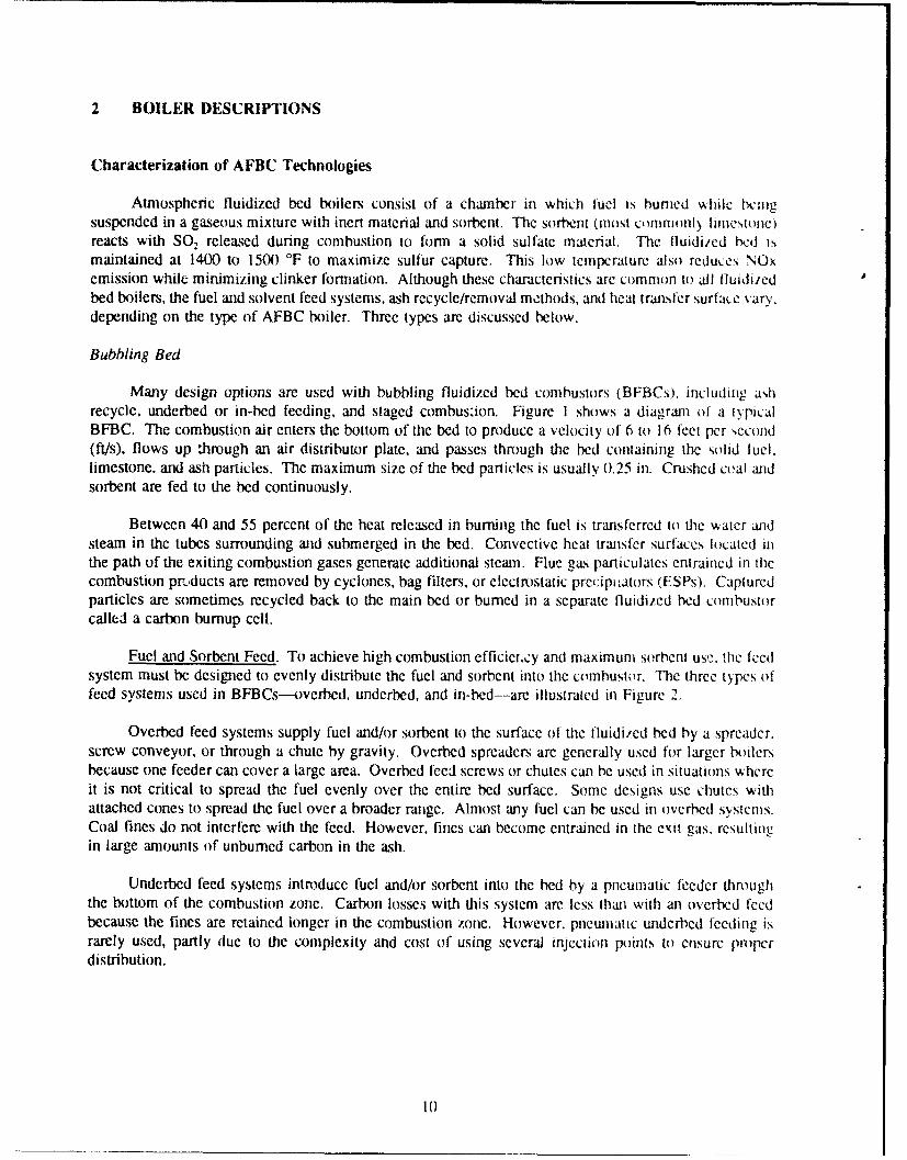
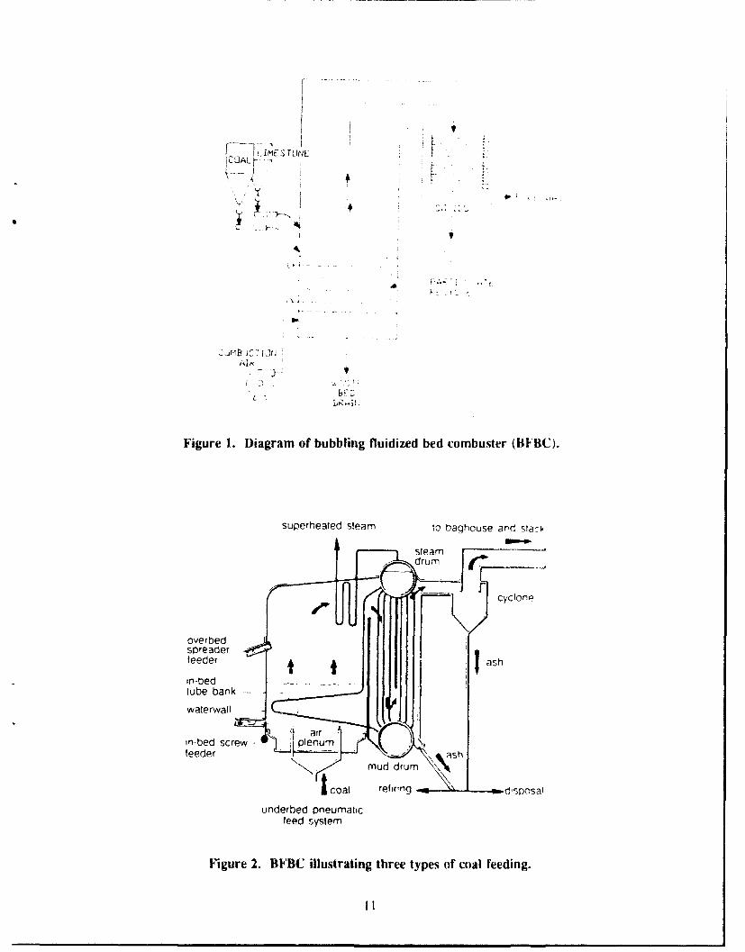
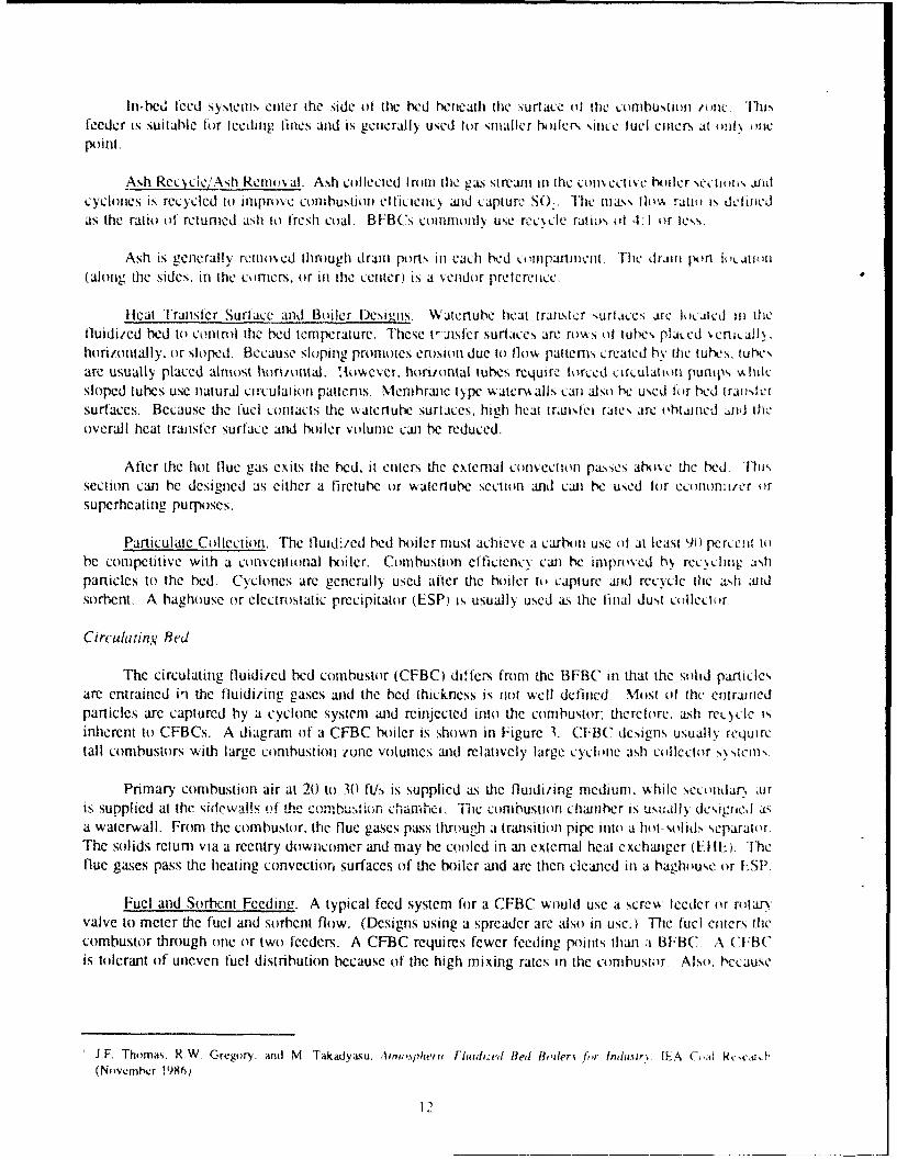
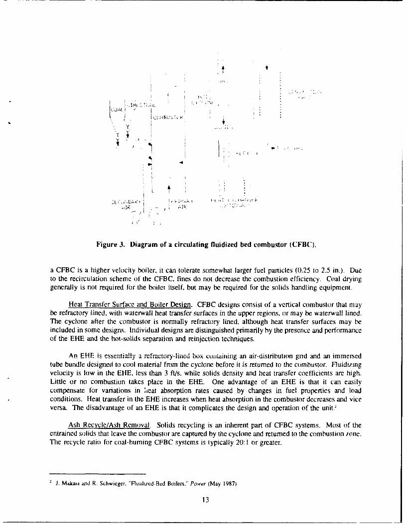
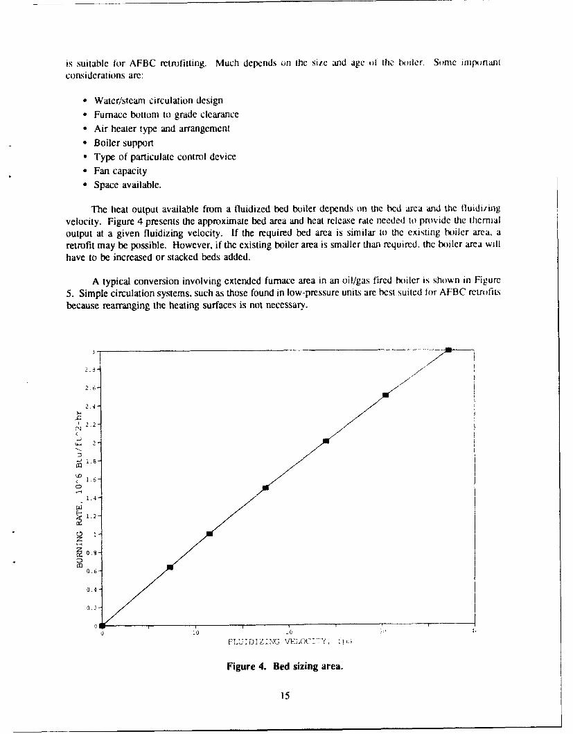

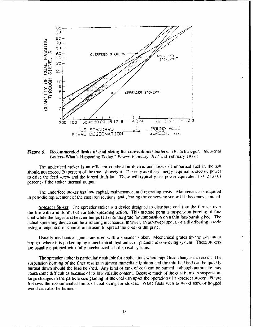

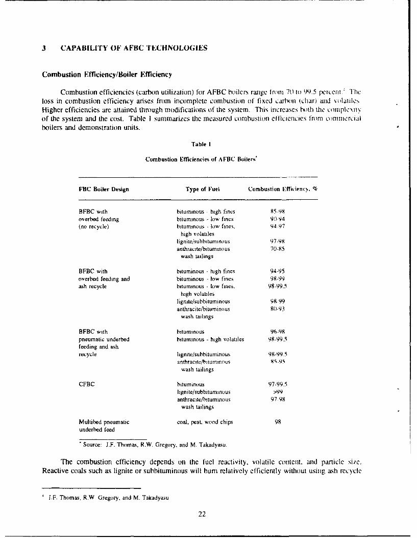
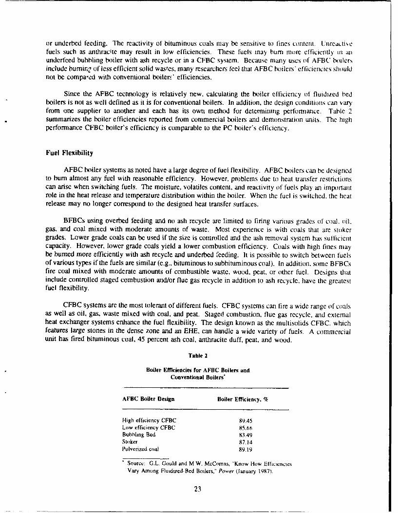
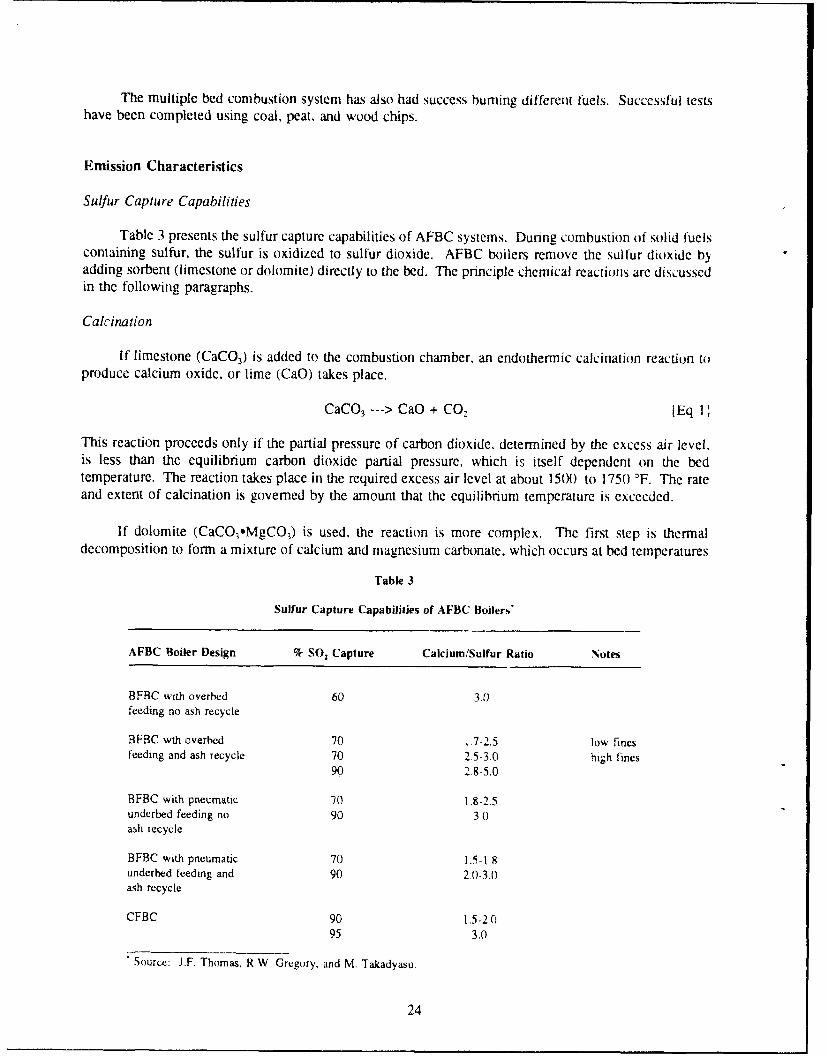
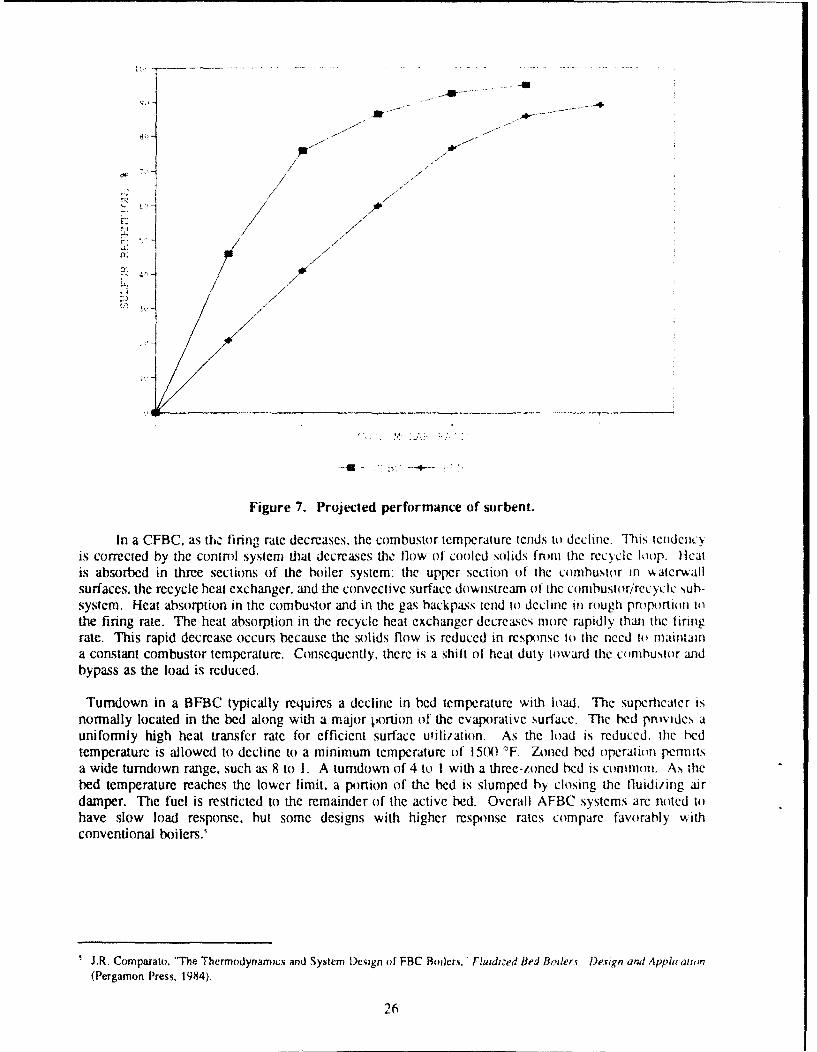
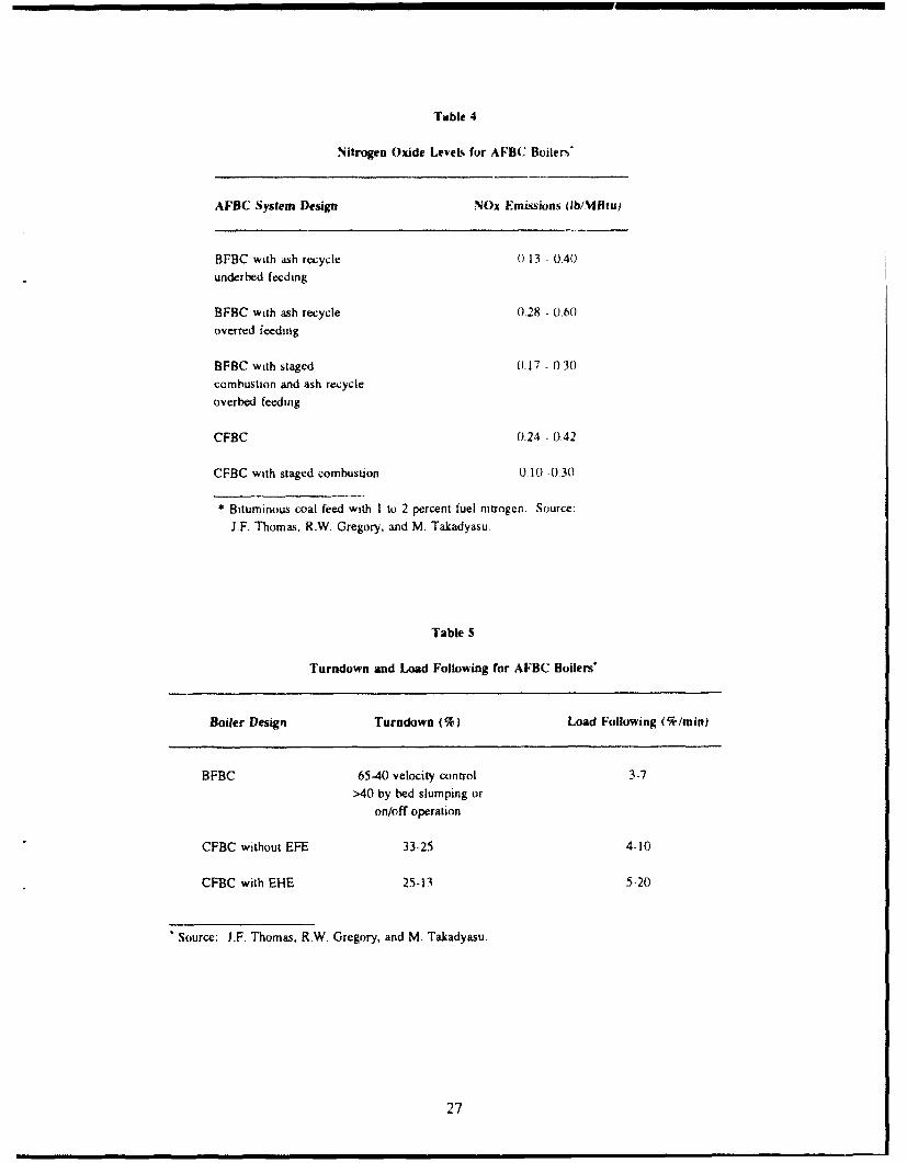
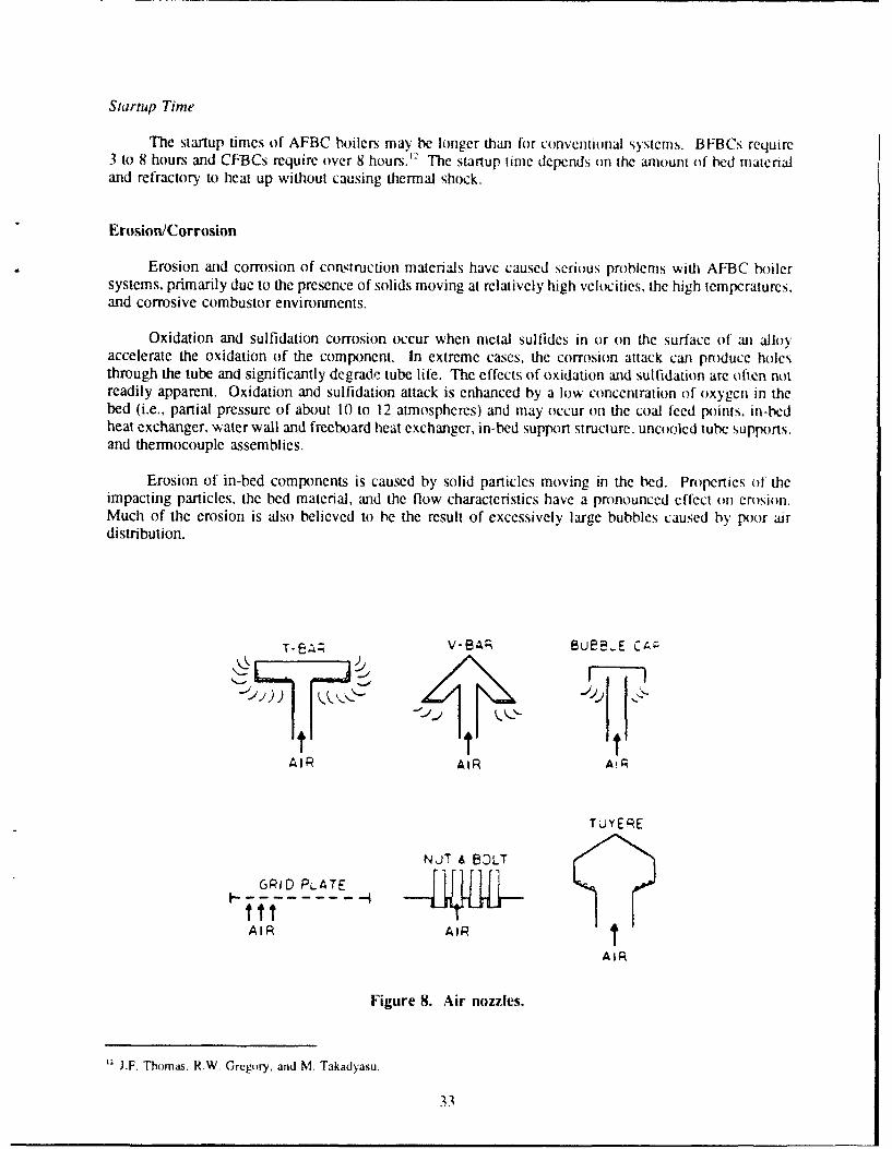
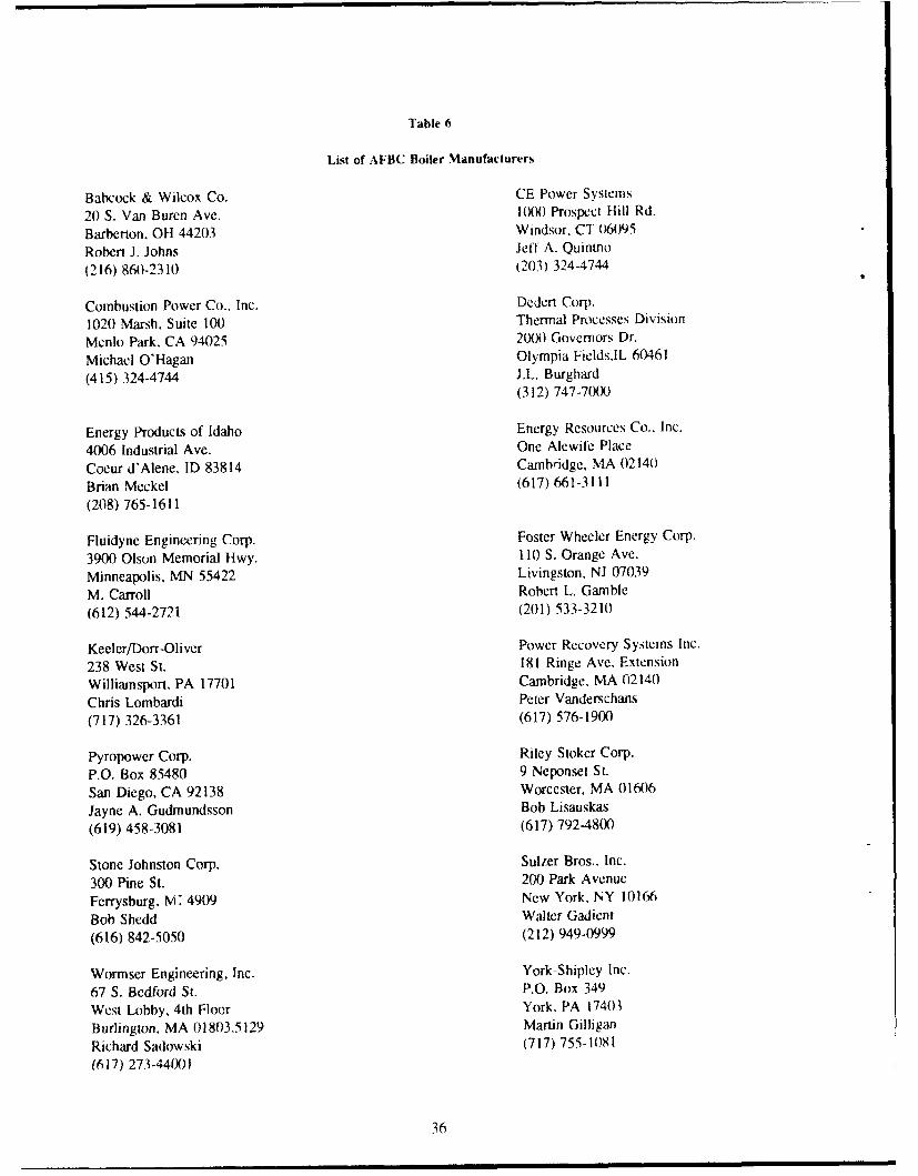
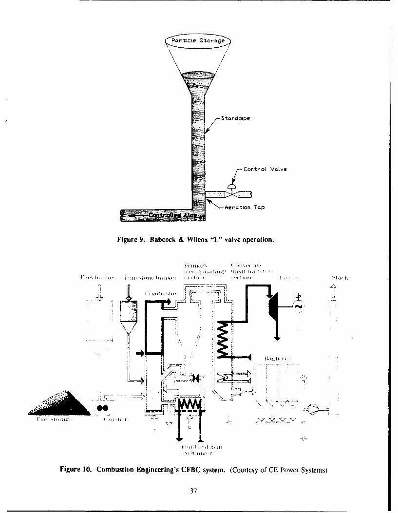
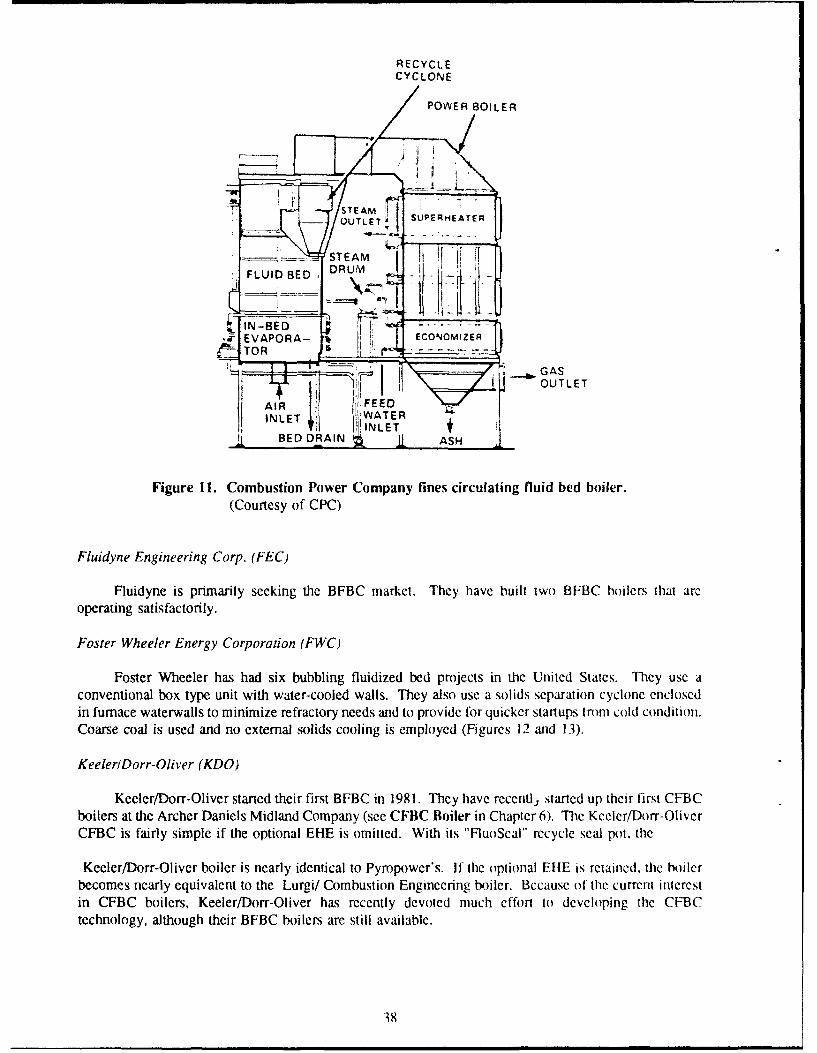
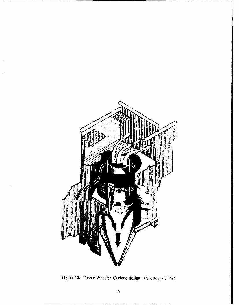
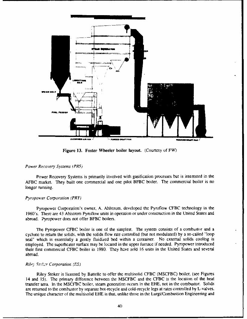
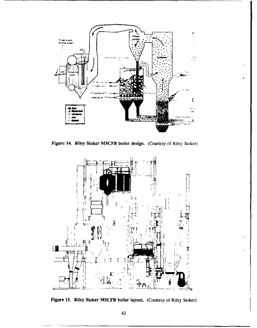
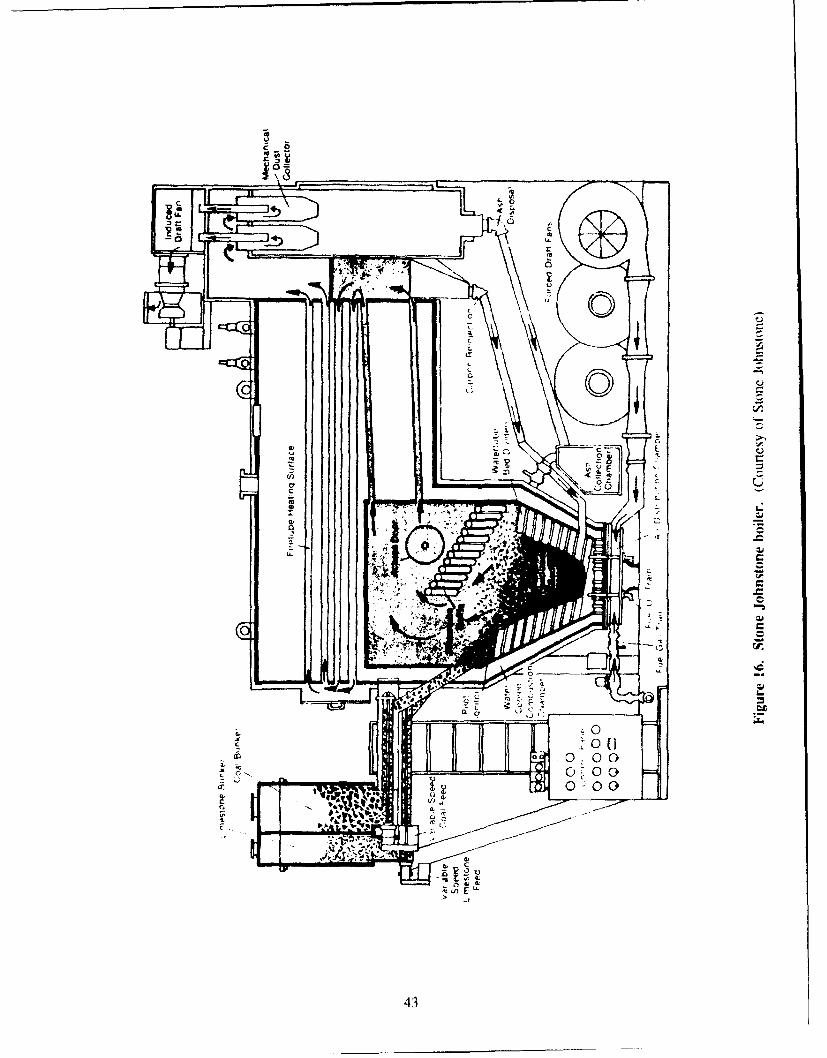
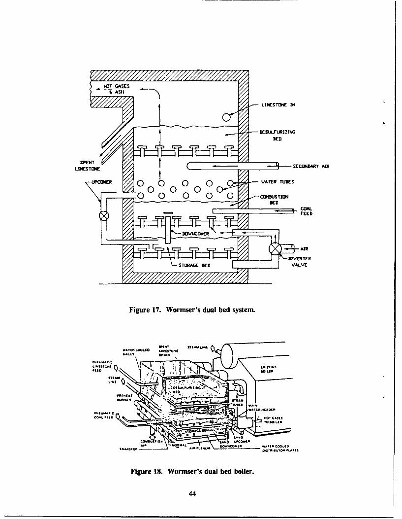
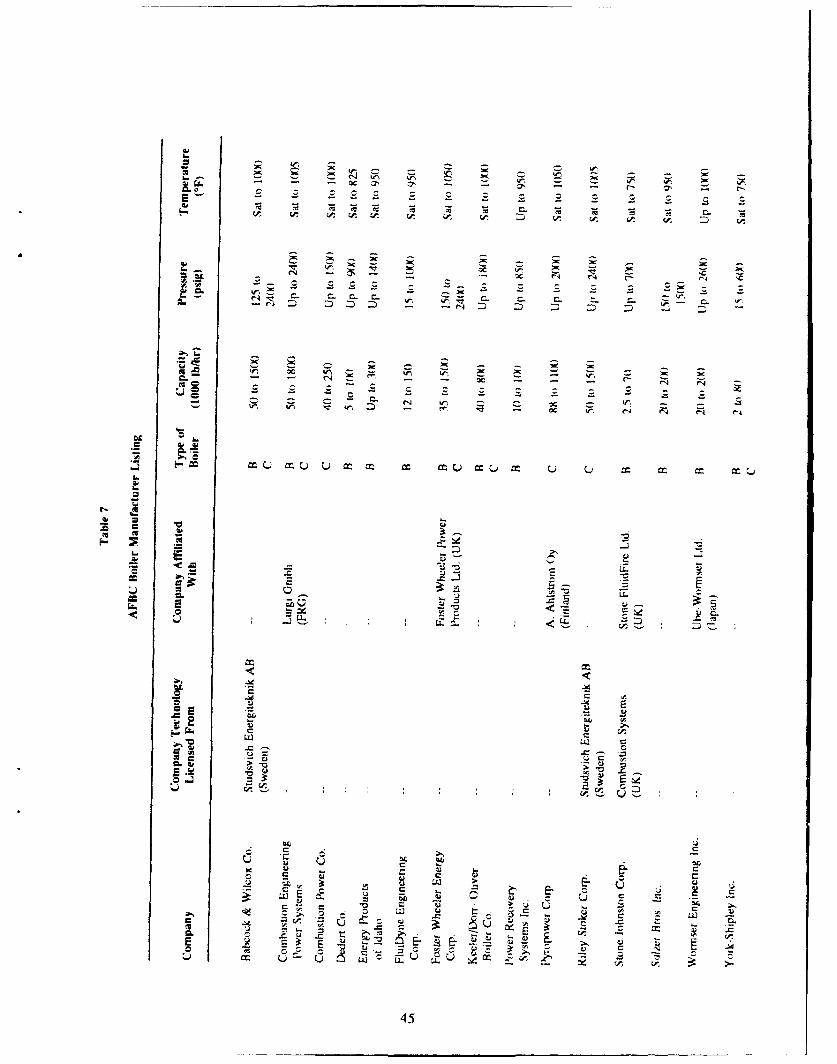
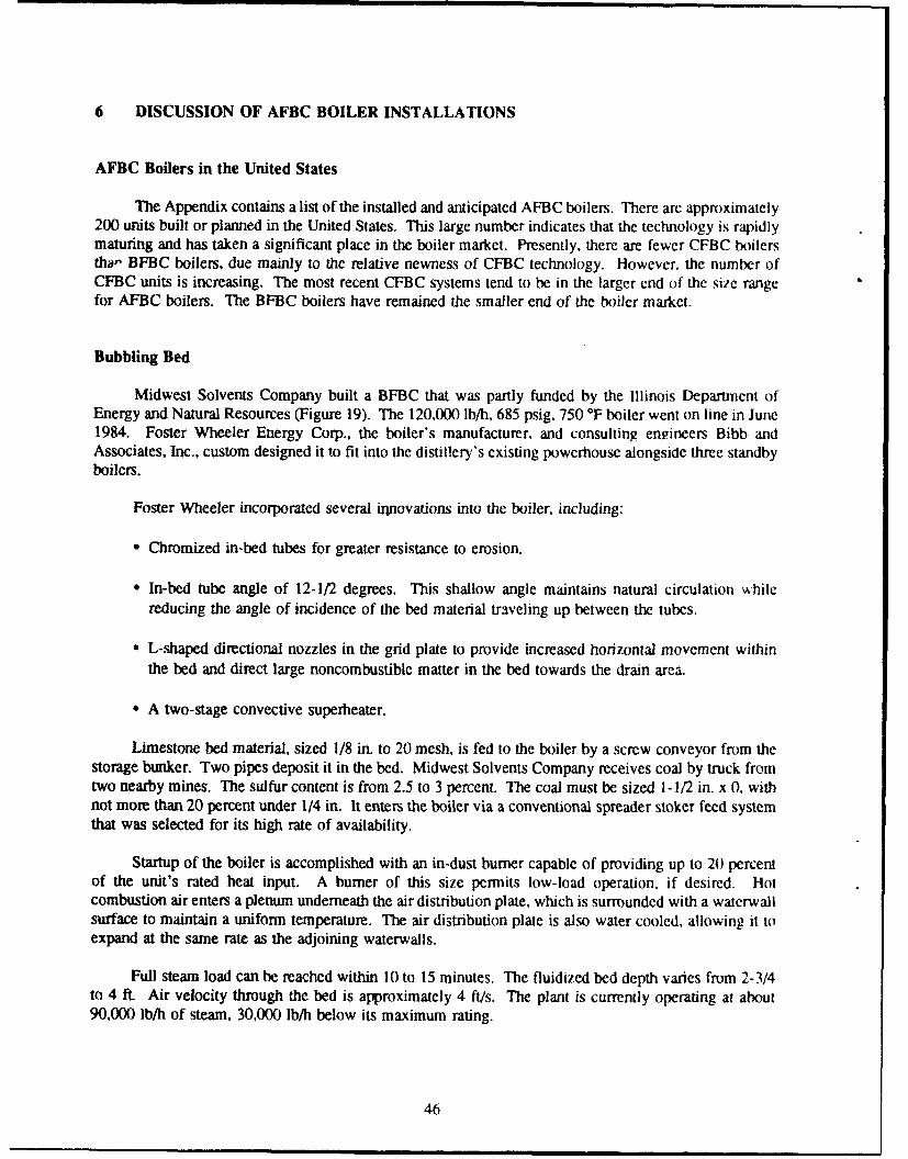
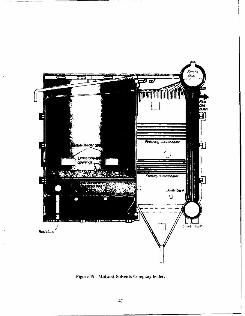
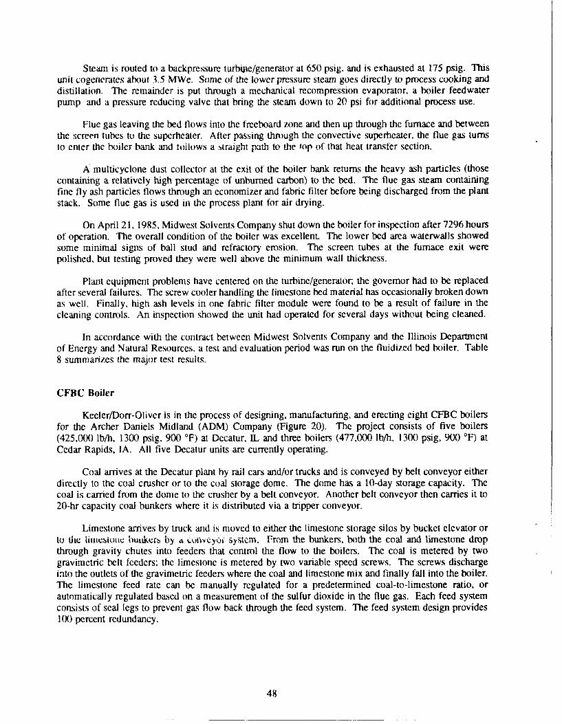
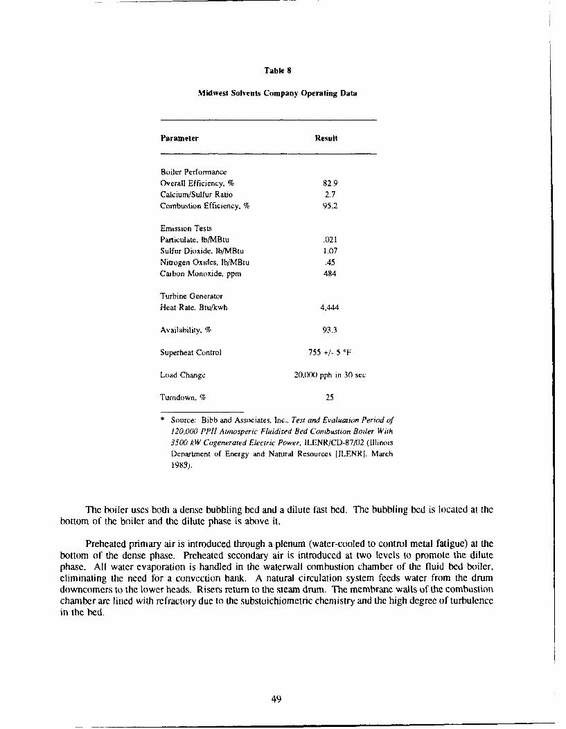
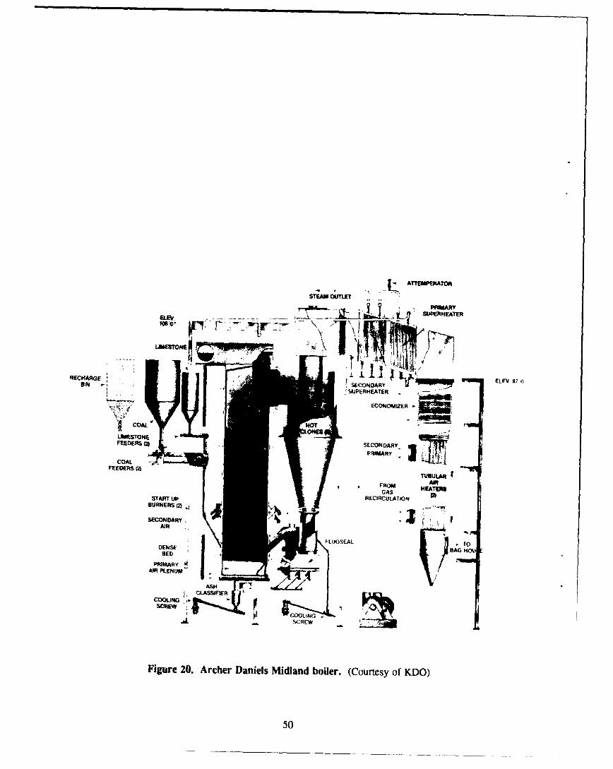
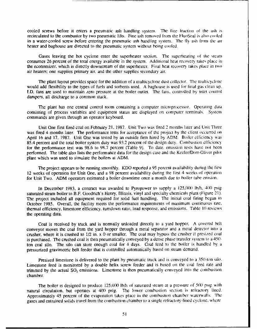
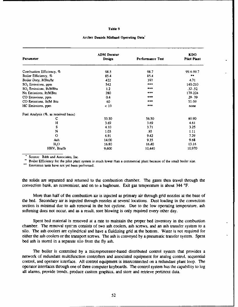
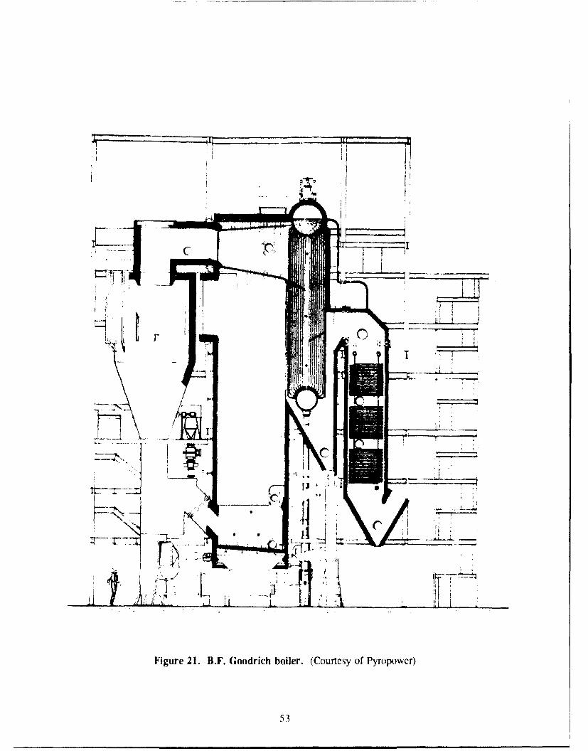
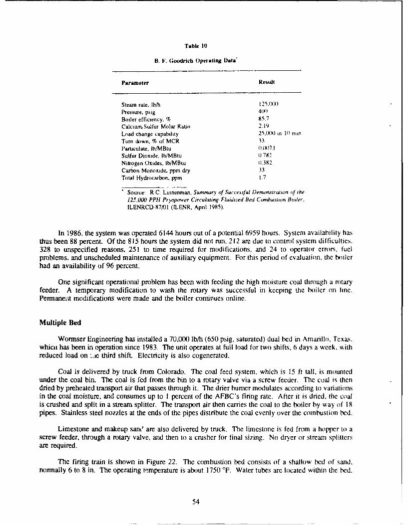
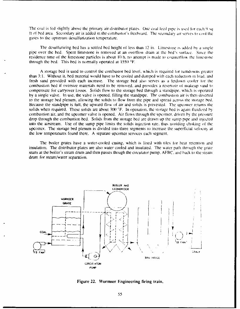

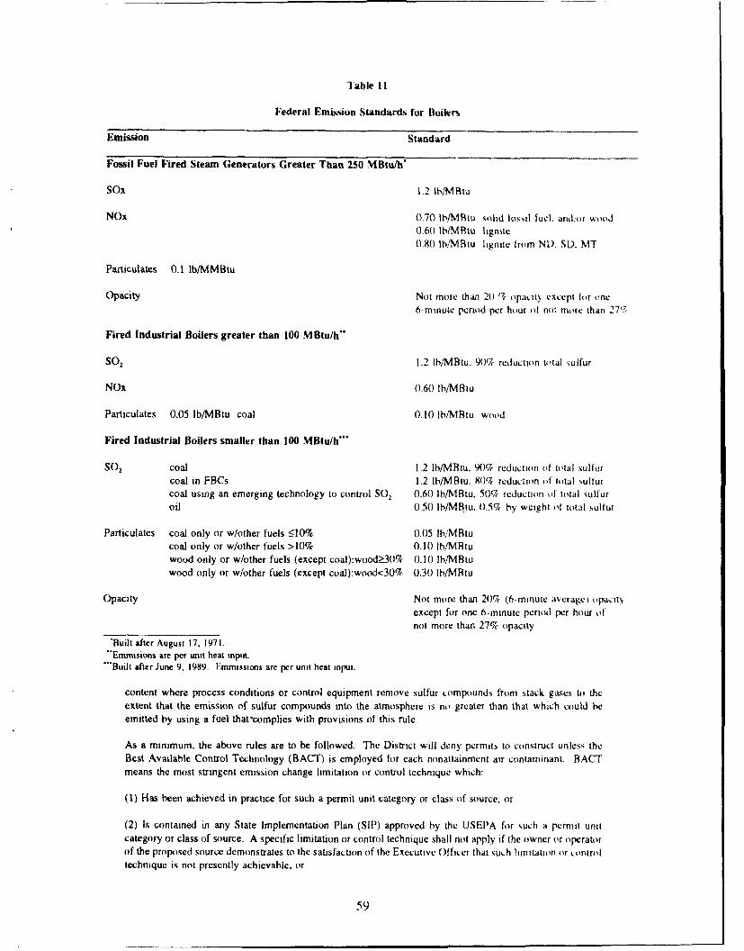
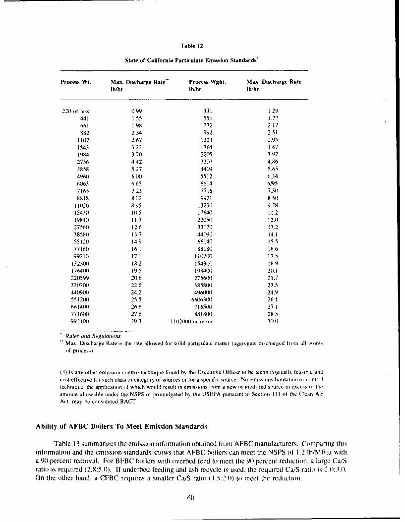
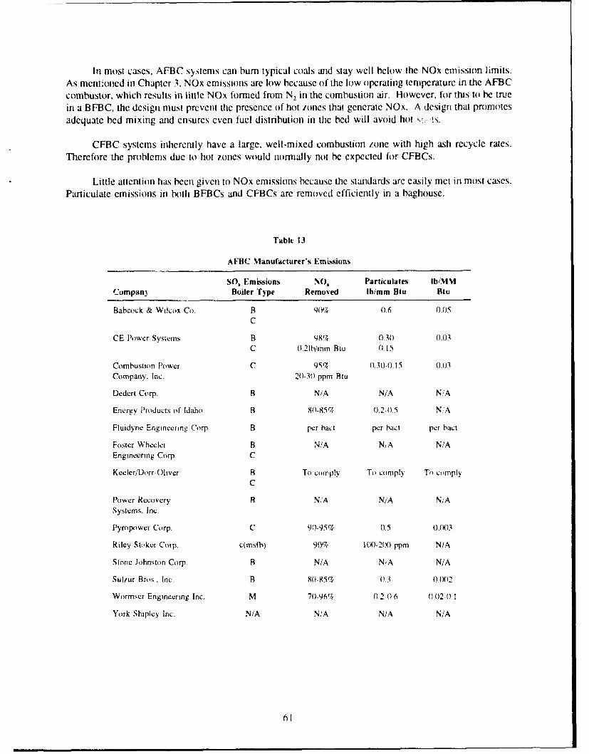
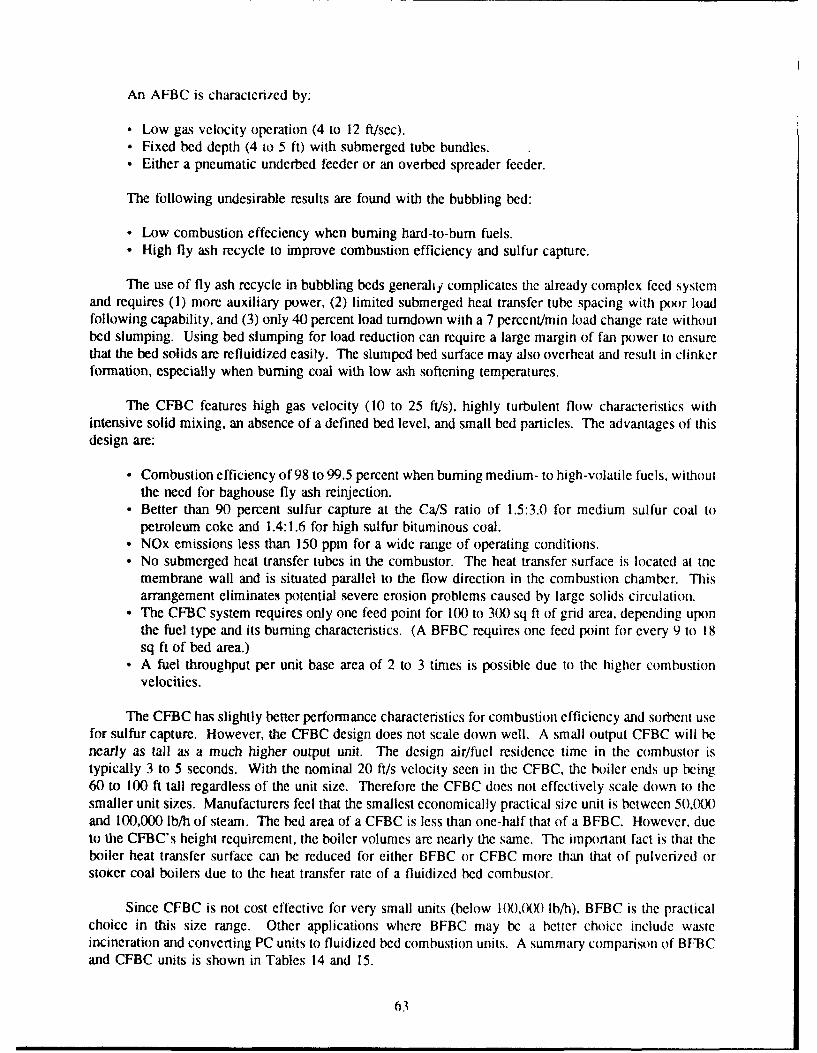
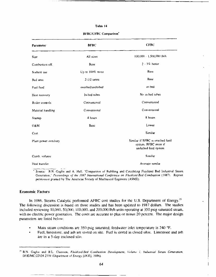

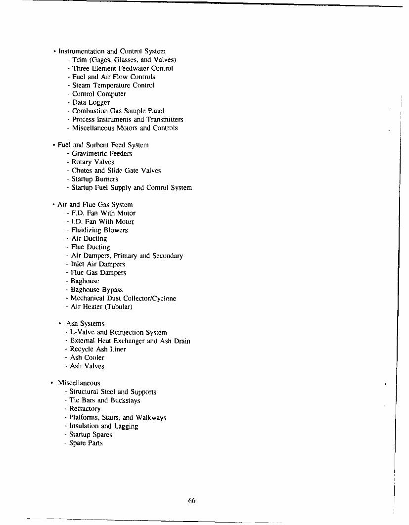
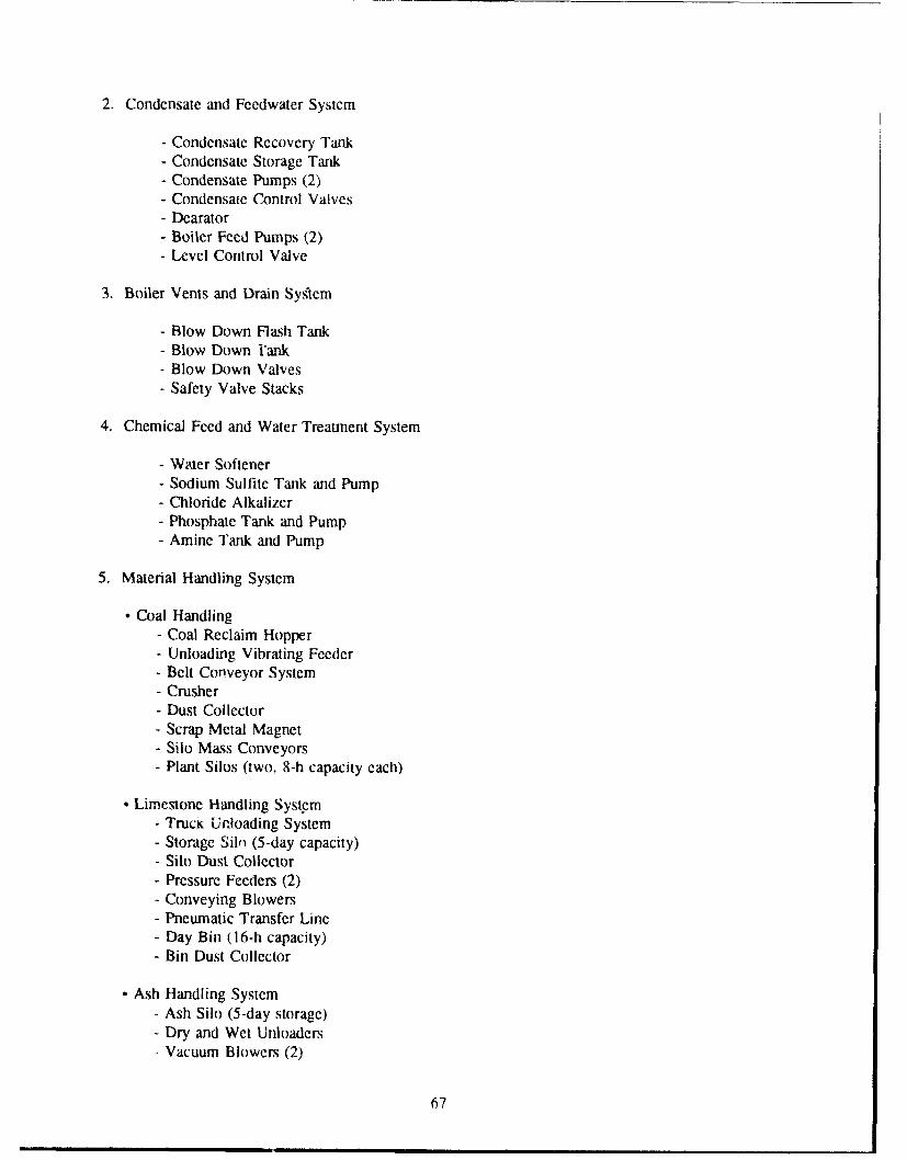
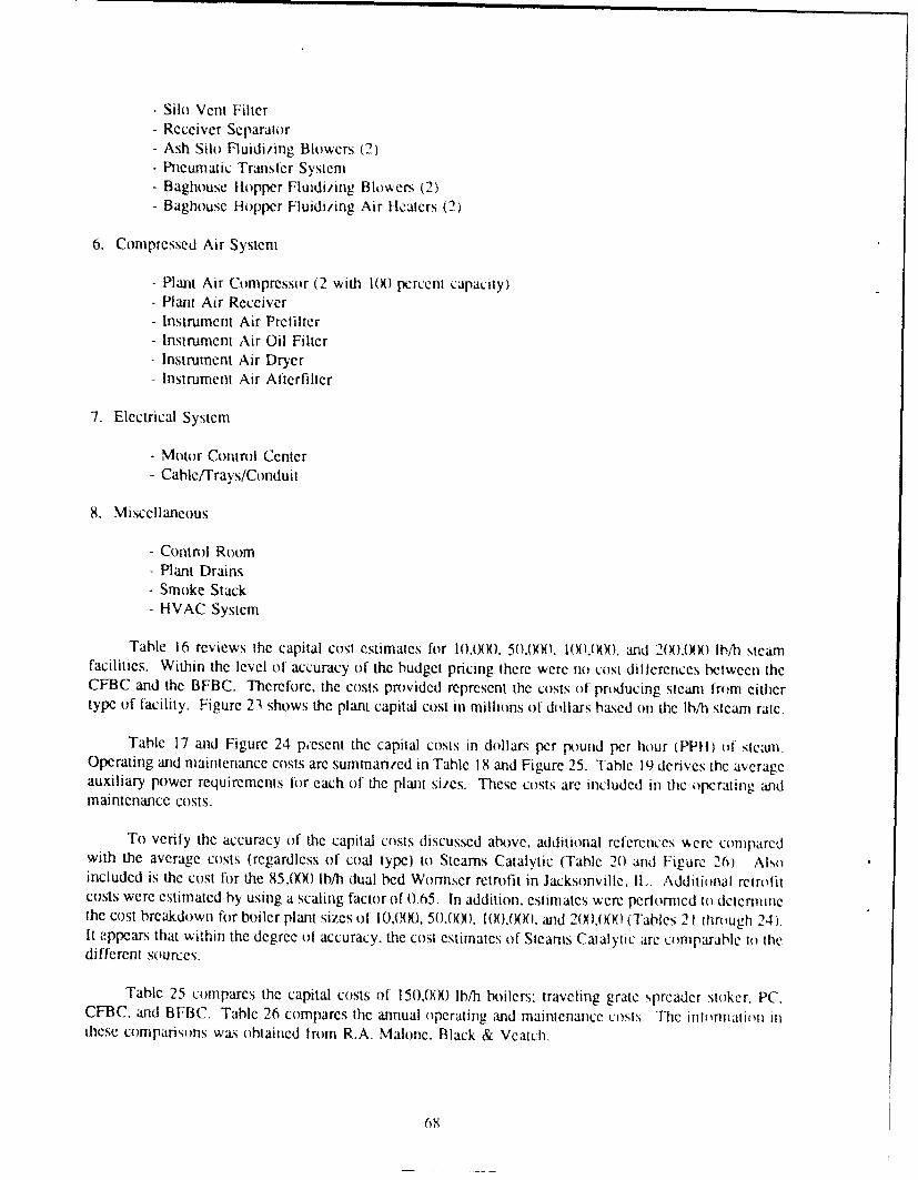
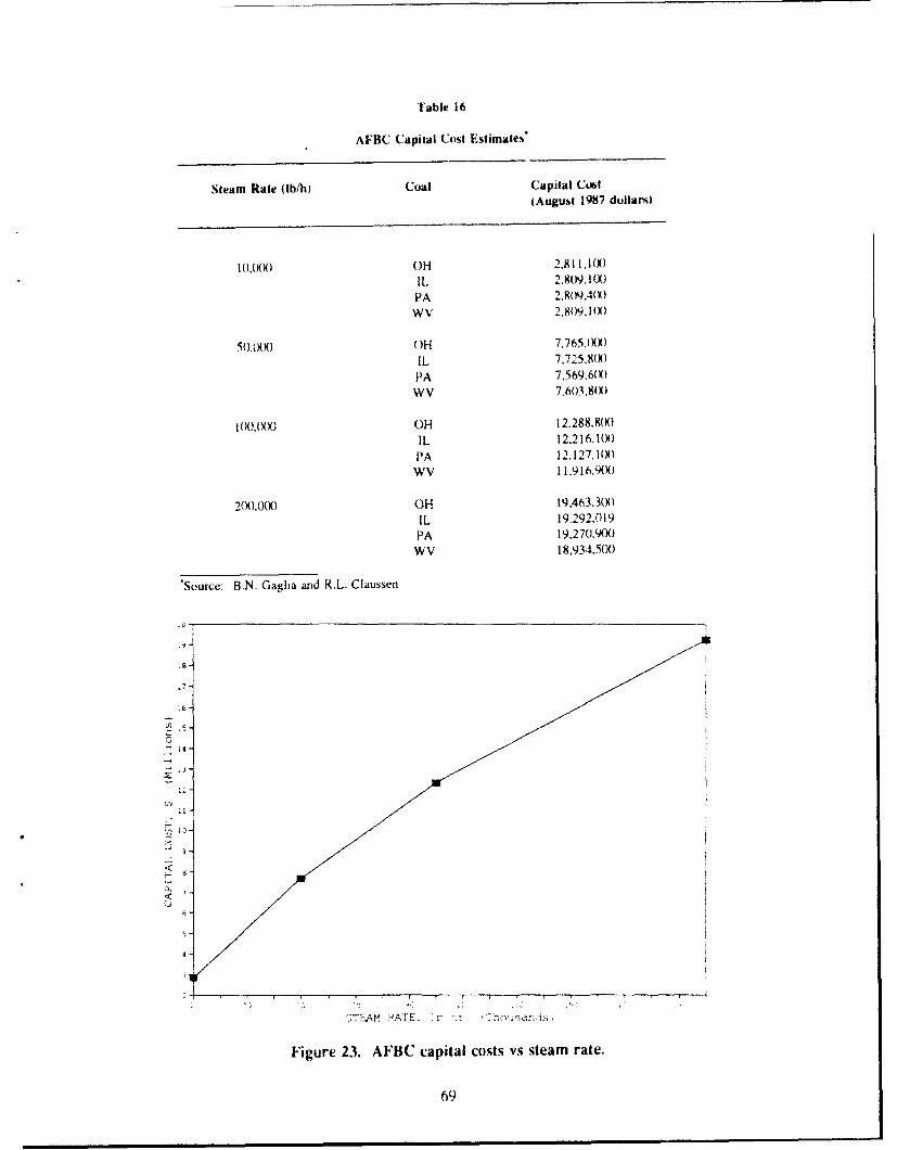
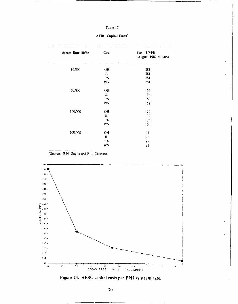
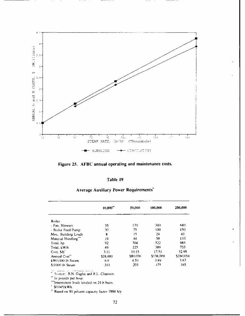
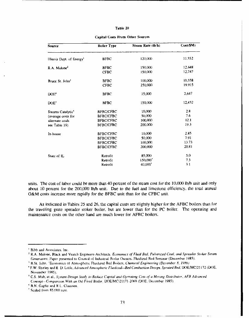
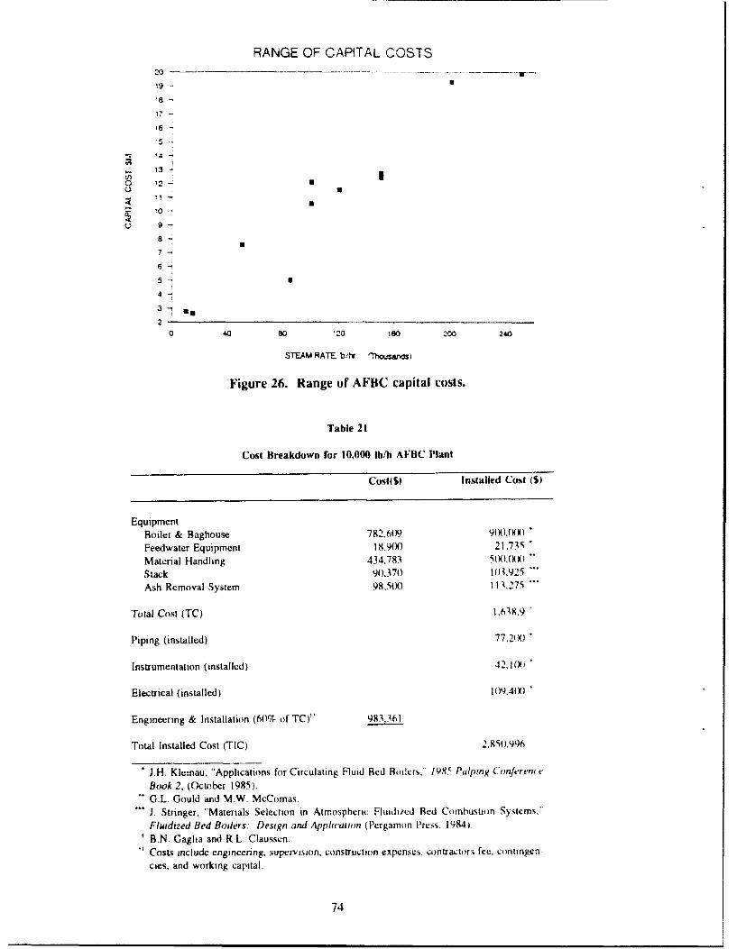
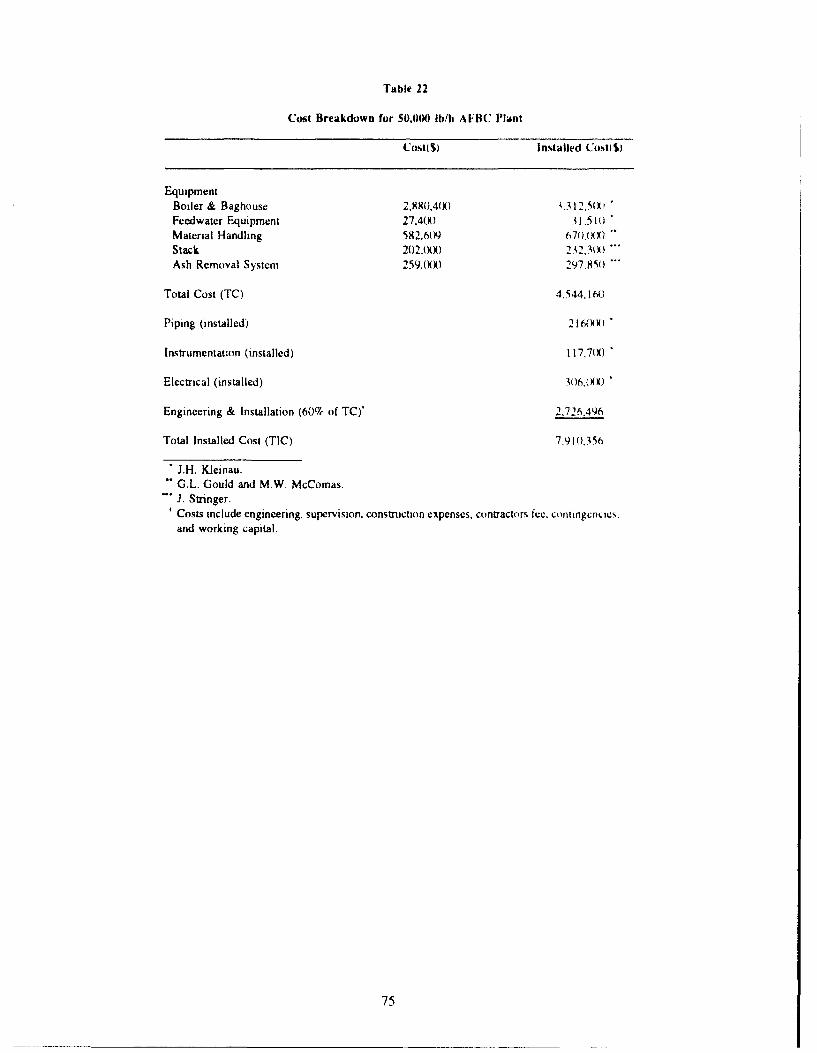
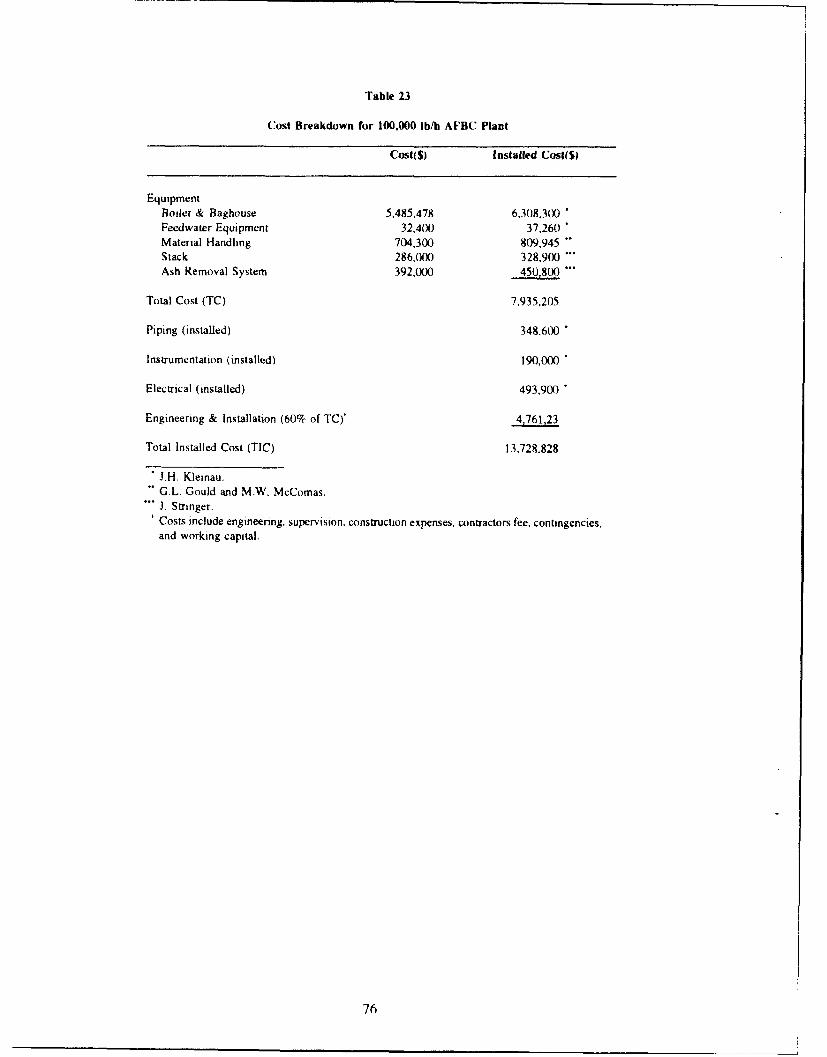
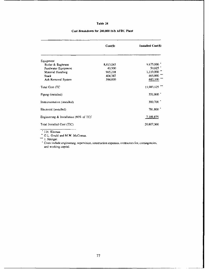
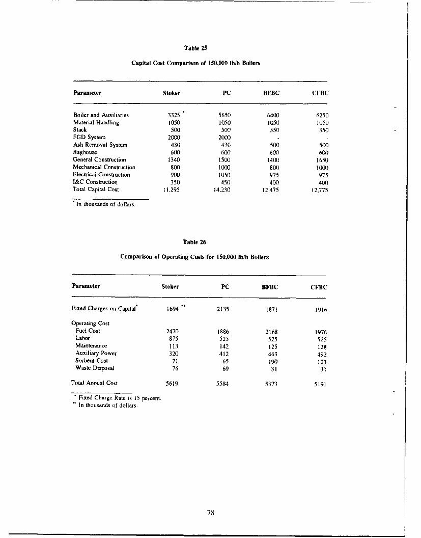
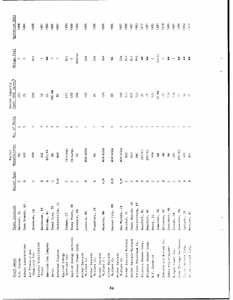
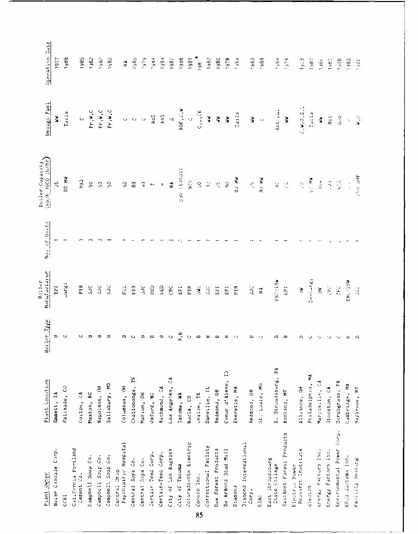
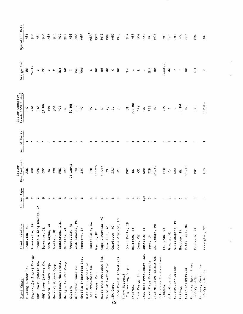
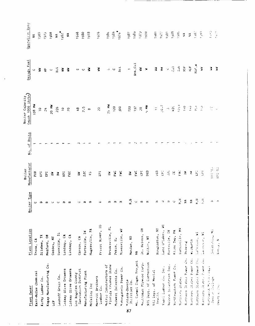
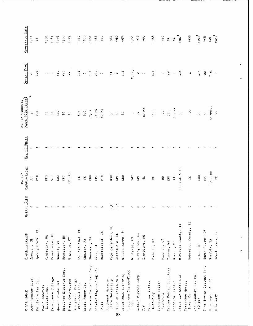
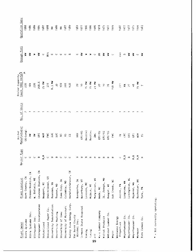
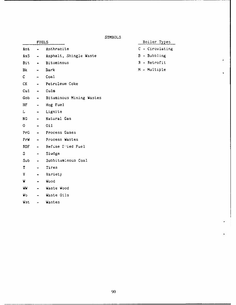
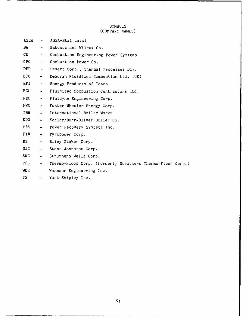


![AD-A262 '111 J I 'i t! ill~J],! 754 I~li iii IIHOSPITALITY ... · collected from either top management company personnel and/or ... responding to the many follow-up phone calls. In](https://static.documents.pub/doc/80x56/5f3dc3e7b67bbd153e144d2c/ad-a262-111-j-i-i-t-illj-754-ili-iii-iihospitality-collected-from-either.jpg)


