13
NPOWER 400 WATT WIND TURBINE INSTRUCTION MANUAL Serial# _______ dan kruger [Pick the date] Item# 21172
| Date post: | 26-Mar-2018 |
| Category: |
Documents |
| Upload: | duongkhanh |
| View: | 218 times |
| Download: | 2 times |
NPOWER400WATTWINDTURBINEINSTRUCTIONMANUAL
Serial#_______
dankruger
[Pickthedate]
Item#21172

2
1. Introduction:
This manual contains installation and safety information for the NPower 400 Watt Wind Turbine, Item# 21172. The information in this manual is believed to be accurate and reliable; however, The Distributor assumes no responsibility for inaccuracies or omissions. NPower reserves the right to make changes to this product specification, or its manual, without prior notice. Therefore, check the NPower Website for updates as necessary.
The NPower 400 Watt Wind Turbine, like other sources of electrical power, must be installed following the guidelines established by state and local regulations. Consult a local electrician or local planning and zoning offices for detailed information about your area.
For your ease write the serial number of your NPower 400 Watt Wind Turbine on the front of this manual. Store your manual and receipt together. You will need this information in the event of a warranty claim.
CONGRATULATIONS!
You will find your new wind turbine easy to install. However, it is important that you read this manual thoroughly prior to installation to assure proper performance and safety. If you have any questions after reading the manual, please contact the Distributor.
Distributedby:NorthernTool+EquipmentCo.,Inc.
Burnsville,MN55306NorthernTool.com
3
Table of Contents
1. PRECAUTIONS 4 1.1 Mechanical Hazards 4 1.2 Electrical Hazards 4 1.3 Installation Precautions 4 1.4 Operation Precautions 5
2. PACKAGE CONTENTS 6
3. WIRING AND INSTALLATION PROCEDURES 7 3.1 System Wiring Diagrams 7 3.2 Single wind generator 8 3.3 Controller Wiring 9 3.4 Attaching to Pole 10 3.5 Step-By-Step Instructions 10
4. ADJUSTING THE REGULATOR 11
5. WARRANTY POLICY 12
6. SPECIFICATIONS 13 6.1Performance Curve 13
4
1. PRECAUTIONS The NPower Wind Turbine has been designed with your safety in mind. However, there are inherent dangers involved with any electrical and/or mechanical equipment. Safety must be your primary concern as you plan the location, installation and operation of the turbine. At all times be aware of electrical, mechanical and rotor blade hazards.
1.1 MECHANICAL HAZARD Rotating blades present the most serious hazard. The rotor blades are made of very strong thermoplastic. At the tip, the blades may be moving at velocities over 275 miles per hour (440 km/hr). At this speed, the tip of a blade is nearly invisible and can cause serious injury. Under no circumstances should you install the turbine where a person could come in contact with moving rotor blades. DO NOT INSTALL THE TURBINE WHERE ANYONE CAN APPROACH THE PATH OF THE BLADES.
1.2 ELECTRICAL HAZARDS *Observe all manufacturers’ safety procedures when working around batteries and other electrical equipment. The NPower Wind Turbine is equipped with sophisticated electronics designed to provide protection from high surge electrical dangers. The internal electronics of the NPower Wind Turbine prevents open circuit voltages from rising above 20 volts for 12-volt systems. Please note that the inherent personal dangers from electrical current still exist, therefore caution should always be used when connecting this and other electrical devices. Heat in wiring systems is often a result of too much current flowing through an undersized wire or through a bad connection.
Batteries can deliver a dangerous amount of current. If a short occurs in the wiring from the batteries, a fire can result. In order to avoid this threat, a properly sized fuse or circuit breaker is required in the lines connecting to the battery. 1.3 INSTALLATION PRECAUTIONS:
Installation procedures should be performed at ground level. Make sure that all batteries are disconnected throughout the installation process. Never install the NPower Wind Turbine upside down. Choose a day when the wind is calm. Have someone available to help during the installation process. Disconnect batteries from turbine wiring. Prior to attaching the wires to the battery, tie the wind turbine output lead wires (positive = red; negative = black) together near the battery to be sure that the rotor will not spin-up during installation.

5
1.4 OPERATION PRECAUTIONS Never approach the turbine during operation.
Check support structures, blades, and electrical systems regularly. The rotor blades are very strong; however, if they come in contact with a solid object, they can break. When performing periodic inspections, or if you must approach the path of the blades, disconnect the power leads from the battery and tie the wind turbine output leads together to stop /slow down the blades from rotating. The turbine can also be shut down through the use of a stop switch.
Note: There is a short break-in period with new wind turbines. The bearings in both the turbine yaw and the turbine rotor will require approximately 60-100 hours of operation in normal wind speeds (approximately 18 – 20 mph, 8 – 9 m/s) before they are running at peak efficiency. During this break-in period, the turbine operation might appear sluggish.

6
2. PACKAGECONTENTS
Use chart below to compare parts. Rotor blades are sharp; handle with care.
1. NoseCone 10.Rotor2. ScrewSocketHead 11.O‐Ring3. Nut‐Jam‐SAE5/8‐18 12.BodyAssembly4. Blade 13.SnapRing‐32MMExternal5. HUB 14.YawShaftAssembly6. Nut‐Nylock‐SAE6‐32 15.WindGeneratorController12V7. ScrewSockethead10‐24x1‐1/2” 16.CircuitBreaker8. FaceAssembly 17.StopSwitch9. Stator
7
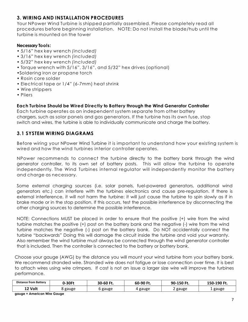
3. WIRING AND INSTALLATION PROCEDURES Your NPower Wind Turbine is shipped partially assembled. Please completely read all procedures before beginning installation. NOTE: Do not install the blade/hub until the turbine is mounted on the tower Necessary Tools: • 5/16” hex key wrench (included) • 3/16” hex key wrench (included) • 5/32” hex key wrench (included) • Torque wrench with 5/16”, 3/16”, and 5/32” hex drives (optional) •Soldering iron or propane torch • Rosin core solder • Electrical tape or 1/4” (6-7mm) heat shrink • Wire strippers • Pliers Each Turbine Should be Wired Directly to Battery through the Wind Generator Controller Each turbine operates as an independent system separate from other battery chargers, such as solar panels and gas generators. If the turbine has its own fuse, stop switch and wires, the turbine is able to individually communicate and charge the battery. 3.1 SYSTEM WIRING DIAGRAMS
Before wiring your NPower Wind Turbine it is important to understand how your existing system is wired and how the wind turbines interior controller operates.
NPower recommends to connect the turbine directly to the battery bank through the wind generator controller, to its own set of battery posts. This will allow the turbine to operate independently. The Wind Turbines internal regulator will independently monitor the battery and charge as necessary.
Some external charging sources (i.e. solar panels, fuel-powered generators, additional wind generators etc.) can interfere with the turbines electronics and cause pre-regulation. If there is external interference, it will not harm the turbine: it will just cause the turbine to spin slowly as if in brake mode or in the stop position. If this occurs, test the possible interference by disconnecting the other charging sources to determine the possible interference.
NOTE: Connections MUST be placed in order to ensure that the positive (+) wire from the wind turbine matches the positive (+) post on the battery bank and the negative (-) wire from the wind turbine matches the negative (-) post on the battery bank. Do NOT accidentally connect the turbine “backwards” Doing this will damage the circuit inside the turbine and void your warranty. Also remember the wind turbine must always be connected through the wind generator controller that is included. Then the controller is connected to the battery or battery bank.
Choose your gauge (AWG) by the distance you will mount your wind turbine from your battery bank. We recommend stranded wire. Stranded wire does not fatigue or lose connection over time. It is best to attach wires using wire crimpers. If cost is not an issue a larger size wire will improve the turbines performance. DistancefromBattery 0‐30Ft 30‐60Ft. 60‐90Ft. 90‐150Ft. 150‐190Ft.
12Volt 8gauge 6gauge 4gauge 2gauge 1gaugegauge = American Wire Gauge

8
3.2 SINGLE WIND GENERATOR
Choose the appropriate suggested wiring diagram below for proper wiring information.
WireColorCodesRed=PositiveBlack=NegativeGreen=Ground

9
3.3 CONTROLLER WIRING
10
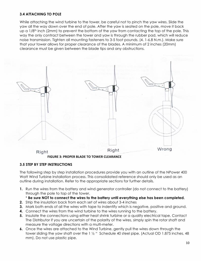
3.4 ATTACHING TO POLE
While attaching the wind turbine to the tower, be careful not to pinch the yaw wires. Slide the yaw all the way down over the end of pole. After the yaw is seated on the pole, move it back up a 1/8th inch (2mm) to prevent the bottom of the yaw from contacting the top of the pole. This way the only contract between the tower and yaw is through the rubber pad, which will reduce noise transmission. Tighten all mounting fasteners to 3-5 foot pounds. (4. 1-6.8 N.m.). Make sure that your tower allows for proper clearance of the blades. A minimum of 2 inches (20mm) clearance must be given between the blade tips and any obstructions.
FIGURE3:PROPERBLADETOTOWERCLEARANCE
3.5 STEP BY STEP INSTRUCTIONS
The following step by step installation procedures provide you with an outline of the NPower 400 Watt Wind Turbine Installation process. This consolidated reference should only be used as an outline during installation. Refer to the appropriate sections for further details.
1. Run the wires from the battery and wind generator controller (do not connect to the battery) through the pole to top of the tower. * Be sure NOT to connect the wires to the battery until everything else has been completed.
2. Strip the insulation back from each set of wires about 3-4 inches 3. Mark both ends of all the wires with tape to indentify which is negative, positive and ground. 4. Connect the wires from the wind turbine to the wires running to the battery. 5. Insulate the connections using either heat shrink turbine or a quality electrical tape. Contact
The Distributor if you are uncertain of the polarity of the wires, simply spin the rotor shaft and measure the voltage directions with a multi-meter.
6. Once the wires are attached to the Wind Turbine, gently pull the wires down through the tower sliding the yaw shaft over the 1 ½ “ Schedule 40 steel pipe. (Actual OD 1.875 inches, 48 mm). Do not use plastic pipe.
11
7. Slide the yaw shaft all the way down over the end of pole being careful not to pinch the yaw wires. Be sure to leave enough slack in the wires so that if necessary, the turbine can be removed.
8. After the yaw is all the way onto the pole, move it back up 1/8th Inch (2mm) to prevent the bottom of the yaw from contacting the top of the pole. The only contact between the tower and yaw is through the rubber pad which will reduce the transmission of noise down the tower.
9. Once the yaw shaft is on the tower, firmly tighten the yaw clamp screws with the 5/32 hex key to 3-5 food pound (4.1-6.8 Nm). The NPower Wind Turbine should yaw freely without restrictions.
10. Check your NPower Wind Turbine to be sure that it is securely attached to the mounts. Remember that this attachment will have to hold in high winds.
11. Remove the nut on the rotor shaft, and carefully attaché the assembled hub and blades to the shaft without pushing the rotor shaft into the turbine
12. Run all wires from the turbine to the battery (Do not connect wires to the battery). Be sure to crimp and solder the connection using the appropriate sized connectors.
13. Attach your positive (RED) wire to a fuse. 14. Make sure that your system is properly grounded before proceeding. 15. Before attaching the wiring to the battery, make sure that:
a. All circuit breakers are on the off position b. The stop switch is in the “Stop” or shorted position (if installed)
16. Attach wires to the battery. Red wire to positive, Black wire to Negative. 17. Turn on the circuit breakers and or stop switch. 18. When the NPower Wind Turbine is first connected to the battery bank, the microprocessor will
blink the LED twice to indicate that the control circuit is running correctly. Once the blades reach. 500RPM, the turbine will begin charging and the LED will turn on. The LED can be difficult to see during the day.
19. Your installation process is complete.
IMPORTANT: Severe Unit Damage May Result from Improper Grounding failure to properly ground the turbine will void your warranty.
4. ADJUSTING THE REGULATOR
It is important to understand how to use the NPower Wind Turbine controller electronics, to ensure proper charging of your batteries.
The voltage regulator is factory set at 14.1 (28.8) volts. The factory setting is marked on the casting with a small indentation aligned with the screw slot.
To change the setting on the voltage regulator, rotate the adjusting screw with 1/8 turn for each 0.42 (85) volt change desired. For example, if you want to adjust your voltage regulator to 14.52 (29.05) volts, turn the adjusting screw clockwise by 1/8th turn. Rotating the adjustment screw counter-clockwise by 1/8th turn will lower the regulation setting by .42 (.85) volts.
The adjustment screw will provide regulation settings for voltage ranges at least as wide as those listed below. The actual voltage set point at the extreme counter-clockwise position may be as much as 10% lower than the value listed, and at the extreme clockwise position may be up to 10% higher the value listed.
12
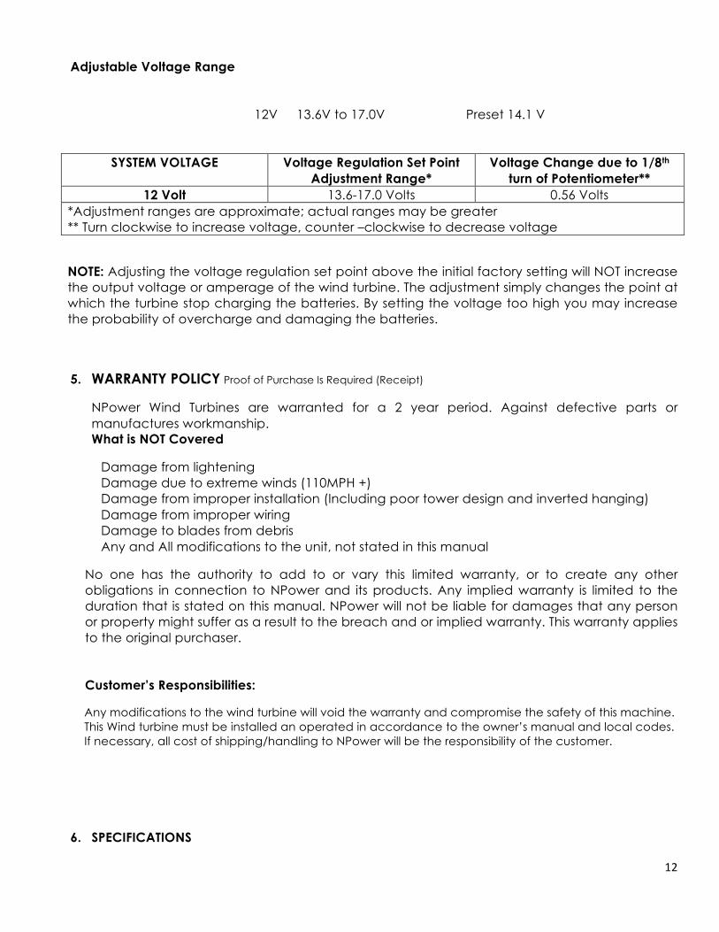
Adjustable Voltage Range
12V 13.6V to 17.0V Preset 14.1 V
SYSTEM VOLTAGE Voltage Regulation Set Point Adjustment Range*
Voltage Change due to 1/8th turn of Potentiometer**
12 Volt 13.6-17.0 Volts 0.56 Volts *Adjustment ranges are approximate; actual ranges may be greater ** Turn clockwise to increase voltage, counter –clockwise to decrease voltage
NOTE: Adjusting the voltage regulation set point above the initial factory setting will NOT increase the output voltage or amperage of the wind turbine. The adjustment simply changes the point at which the turbine stop charging the batteries. By setting the voltage too high you may increase the probability of overcharge and damaging the batteries.
5. WARRANTY POLICY Proof of Purchase Is Required (Receipt)
NPower Wind Turbines are warranted for a 2 year period. Against defective parts or manufactures workmanship. What is NOT Covered
� Damage from lightening � Damage due to extreme winds (110MPH +) � Damage from improper installation (Including poor tower design and inverted hanging) � Damage from improper wiring � Damage to blades from debris � Any and All modifications to the unit, not stated in this manual
No one has the authority to add to or vary this limited warranty, or to create any other obligations in connection to NPower and its products. Any implied warranty is limited to the duration that is stated on this manual. NPower will not be liable for damages that any person or property might suffer as a result to the breach and or implied warranty. This warranty applies to the original purchaser. Customer’s Responsibilities:
� Any modifications to the wind turbine will void the warranty and compromise the safety of this machine. � This Wind turbine must be installed an operated in accordance to the owner’s manual and local codes. � If necessary, all cost of shipping/handling to NPower will be the responsibility of the customer.
6. SPECIFICATIONS

13
MODEL#70400 NPower400WattWindTurbineUPC 8392900070446ROTORDIAMETER 47.2”or1.2MeterWEIGHT 12.3lbsor5.6KGSTARTUPWINDSPEED 6.7MPHor3m/sCHARGESPEED 5.6MPHor2.5m/sVOLTAGE 12VoltsMAXIMUMWINDSPEED 110MPHRATEDPOWER 400Wattsat28MPH/12.5m/sWindSpeedTURBINECONTROLLER ExternalController‐WindGeneratorControllerBLADES CarbonFibreCompositeBODY CastAluminumPOLEDIMENSIONS 1.5Inchinschedule40pipe
6.1 Performance Curves
� Performancechartshowsapproximatenumbersonly
� � Distributedby:
� NorthernTool+EquipmentCo.,Inc.� Burnsville,MN55306� NorthernTool.com
12Volt
0100200300400500600
12Volt
24Volt


