NPS-ME-00-001 NAVAL POSTGRADUATE SCHOOL MONTEREY, CALIFORNIA Technical Report Approved for public release; distribution unlimited. The Surface Warfare Test Ship by Faculty Members: Charles N. Calvano Robert C. Harney Student Members: LT David Wickersham, USN, team leader LTjg Ioannis Farsaris, Helenic Navy LT Philip Malone, USN LCDR David Ruley, USN LT Nathan York January 2000
Transcript
NPS-ME-00-001
NAVAL POSTGRADUATE SCHOOL MONTEREY, CALIFORNIA
Technical Report
Approved for public release; distribution unlimited.
The Surface Warfare Test Ship
by
Faculty Members: Charles N. Calvano Robert C. Harney Student Members: LT David Wickersham, USN, team leader LTjg Ioannis Farsaris, Helenic Navy LT Philip Malone, USN LCDR David Ruley, USN LT Nathan York
January 2000
NAVAL POSTGRADUATE SCHOOL Rear Admiral Robert C. Chaplin Dr. Richard Elster
Superintendent Provost This report was prepared as an integral part of the Total Ship Systems Engineering (TSSE)
educational process. Small amounts of funding from the Port Hueneme Division of the Naval Surface
Warfare Center were used only for minor student travel incident to performing the design documented
herein. The work described was performed between July and December 1999.
This report was prepared by: Charles N. Calvano Robert C. Harney Director, Total Ship Systems TSSE Combat Systems Chair Professor, Mechanical Engineering Dept. Associate Professor, Physics Dept. Reviewed by: Released by: Terry R. McNelley David W. Netzer Chairman and Professor Dean of Research Mechanical Engineering Dept.
REPORT DOCUMENTATION PAGE
Form approved
OMB No 0704-0188 Public reporting burden for this collection of information is estimated to average 1 hour per response, including the time for reviewing instructions, searching existing data sources, gathering and maintaining the data needed, and completing and reviewing the collection of information. Send comments regarding this burden estimate or any other aspect of this collection of information, including suggestions for reducing this burden, to Washington Headquarters Services, Directorate for information Operations and Reports, 1215 Jefferson Davis Highway, Suite 1204, Arlington, VA 22202-4302, and to the Office of Management and Budget, Paperwork Reduction Project (0704-0188), Washington, DC 20503. 1. AGENCY USE ONLY (Leave blank)
2. REPORT DATE 26 January 2000
3. REPORT TYPE AND DATES COVERED
Technical 4. TITLE AND SUBTITLE Surface Warfare Test Ship Design
5. FUNDING
6. AUTHOR(S)
C. N. Calvano & R. C. Harney; LT D. Wickersham, LTjg I. Farsaris, LT P. Malone, LCDR D. Ruley, LT N. York
7. PERFORMING ORGANIZATION NAME(S) AND ADDRESS(ES) Naval Postgraduate School (TSSE Program) Monterey, CA 93943-5000
8. PERFORMING ORGANIZATION REPORT NUMBER NPS-ME-00-001
9. SPONSORING/MONITORING AGENCY NAME(S) AND ADDRESS(ES)
10. SPONSORING/MONITORING AGENCY REPORT NUMBER
11. SUPPLEMENTARY NOTES The views expressed in this report are those of the authors and do not necessarily reflect the official policy or position of the Department of Defense or the U.S. Government. 12a. DISTRIBUTION/AVAILABILITY STATEMENT
Approved for public release; distribution unlimited
12b. DISTRIBUTION CODE
13. ABSTRACT (Maximum 200 words.) A systems engineering approach to the design of a ship conversion to satisfy the requirements for a Surface Warfare Test Ship (SWTS) to be employed by the Port Hueneme Division of the Naval Surface Warfare Center is presented. The ship described would meet test needs for future weapons and sensor systems and provide limited test capability for future hull, mechanical and electrical systems. The current Self Defense Test Ship is over 45 years old, approaching the end of its useful life. A conversion of a de-commissioned SPRUANCE (DD 963) class ship is the basis for the replacement Surface Warfare Test Ship. The study proceeds from mission needs and operational requirements through a functional analysis and study of threat weapons to be employed against the SWTS. After summarizing the characteristics of a SPRUANCE Class ship, the study reports an analysis of four alternative conversion schemes. The alternatives are described, with the rationale for choosing that considered best. The chosen alternative is then described and analyzed in several important areas of concern including combat systems functionality, signature characteristics, engineering plant and habitability for test personnel. The fitness of the proposed design for several special evolutions is also described, and alternatives for further enhancing performance are presented. 14. SUBJECT TERMS Ship Design, Self Defense, Surface Warfare, Systems Engineering, Test Ship
15. NUMBER OF PAGES
266 16. PRICE CODE
17. SECURITY CLASSIFICATION OF REPORT Unclassified
18. SECURITY CLASSIFICATION OF THIS PAGE Unclassified
19. SECURITY CLASSIFICATION OF ABSTRACT Unclassified
20. LIMITATION OF ABSTRACT UL
NSN 7540-01-280-5800 Standard Form 298 (Rev. 2-89) Prescribed by ANSI Std 239-18
The Surface Warfare Test Ship
by
Faculty Members: Charles N. Calvano Robert C. Harney Student Members: LT David Wickersham, USN, team leader LTjg Ioannis Farsaris, Helenic Navy LT Philip Malone, USN LCDR David Ruley, USN
LT Nathan York
The Surface Warfare Test Ship
This report documents a systems engineering and design capstone project undertaken by students
in the Total Ship Systems Engineering program at the Naval Postgraduate School. The project
was performed under the direction of Professors C. N. Calvano and R. C. Harney. The officer
students who comprised the design team were: LT David Wickersham, USN, team leader; LTjg
Ioannis Farsaris, Helenic Navy, LT Philip Malone, USN, LCDR David Ruley, USN, LT Nathan
York, USN
ABSTRACT
A systems engineering approach to the design of a ship conversion to satisfy the
requirements for a Surface Warfare Test Ship (SWTS) to be employed by the Port Hueneme
Division of the Naval Surface Warfare Center is presented. The ship described would meet test
needs for future weapons and sensor systems and provide limited test capability for future hull,
mechanical and electrical systems.
The current Self Defense Test Ship is over 45 years old, approaching the end of its useful
life. A conversion of a decommissioned SPRUANCE (DD 963) class ship is the basis for the
replacement Surface Warfare Test Ship. The study proceeds from mission needs and operational
requirements through a functional analysis and study of threat weapons to be employed against
the SWTS. After summarizing the characteristics of a SPRUANCE Class ship, the study reports
an analysis of four alternative conversion schemes. The alternatives are described, with the
rationale for choosing that considered best. The chosen alternative is then described and
analyzed in several important areas of concern including combat systems functionality, signature
characteristics, engineering plant and habitability for test personnel. The fitness of the proposed
design for several special evolutions is also described, and alternatives for further enhancing
performance are presented.
Faculty Evaluation (This section of the report prepared by the TSSE faculty, Professors Calvano and Harney)
The first four TSSE student capstone designs were performed to meet requirements
established by the faculty – requirements which were essentially “made up”, though realistic and
of potential Navy interest. This design, like its three most recent predecessors, was undertaken at
the suggestion of a “real Navy customer”. Previous designs done for interested parties outside
the Naval Postgraduate School included an Arsenal Ship for the Assistant Secretary of the Navy
(Research, Development, and Acquisition), an all short take-off, vertical landing (STOVL)
aircraft carrier using conventional propulsion for the CVX program office [1], and a Maritime
Pre-Positioning Force 2010 fleet for the Center for Naval Analyses and the U. S. Marine Corps
[2]. This year the Ship Self-Defense Branch of the Port Hueneme Division of the Naval Surface
Warfare Center (NSWCPHD) asked us to look at the design of a replacement for the current
Self-Defense Test Ship (SDTS – the ex-Decatur). The replacement ship, if the program is
approved, is expected to be based on a DD963 class ship, converted for the purpose.
The fact that the SDTS-replacement would be a ship conversion from an existing class of
ship, rather than an entirely new ship design, was a point of concern for the faculty. We were
apprehensive that a conversion project would not be as educationally challenging as a new ship
design. We thought there might be less need for combat systems analysis, there would certainly
be less need for use of the ASSET code in platform design and therefore less emphasis on naval
architecture, and there might be fewer opportunities for innovation. The unquestionable need for
a replacement SDTS coupled with the genuine interest in helping during the design process on
NSWCPHD’s part, overcame our initial hesitation.
As it turned out, our fears were unjustified. Real concerns for safety and survivability drove combat systems analysis and topside design to as high a level of detail as achieved in previous projects. ASSET was still used to evaluate the stability of the modified design. The fact that historical costs were available for SPRUANCE class ships (the class selected for conversion) made possible far better cost estimates than had typically been achieved in the past. In addition, creativity was not stifled in the least. The students researched past and ongoing programs of potential relevance and included many of them in their trade spaces. Innovative ideas they adopted included moving the helicopter landing deck to the bow of the ship, incorporating an enclosed accommodation ladder, adding a boat ramp for barge handling, and significantly reducing the radar cross section of the superstructure, masts, and sensors.
Moving the helicopter landing deck forward of the VLS launchers improves the safety of EOD personnel disarming the weapons after a test (the test weapons of interest are mounted aft) and frees up considerable space for future test projects, without decreasing safety of flight operations. The enclosed accommodation ladder with “French Doors” in the hull removes a source of significant radar cross section, and makes for considerably safer at-sea debarkation and embarkation of research personnel. The boat ramp incorporated into the stern permits the test ship to carry, deploy, and recover its own test barge. This will result in considerable cost savings over the anticipated lifetime of the ship as an additional tug need not be rented to provide barge transport. Simple incorporation of screens, solid panels, and flexible radar absorbing material, alters the rectangular shape of superstructure objects and hides high cross section clutter, at minimal increases in cost and weight.
This year’s team even went so far as to develop initial concepts of damage control
in a highly automated ship during both manned and remote control modes of ship operation. In short the TSSE design satisfied or exceeded all of the requirements of the Mission Need Statement and the Operational Requirements Document. On 9 December 1999 the TSSE team briefed their project before the NPS students and faculty as well as a select audience of individuals from Navsea and other self-defense stakeholders as well as the hierarchy at Port Hueneme. It was exceptionally well received. The TSSE faculty concur with this overall evaluation. Representing the work of only five students working part time for less than 6 months, the attached final report is an outstanding piece of work. In our opinion it is something of which not only the TSSE students and faculty, the Naval Postgraduate School, and NSWC Port Hueneme Division, but also the United States Navy can be proud. [1] A Short Take-Off/Vertical Landing (STOVL) Aircraft Carrier (S-CVX), NPS Report NPS-ME-98-003, May 1998. [2] The Maritime Preposition Force Ship 2010, NPS Report NPS-ME-99-002, April 1999.
SURFACE WARFARE TEST SHIP
TABLE OF CONTENTS
1. Introduction 1-1
2. Current Capabilities 2-1
2.1 Ex-Decatur 2-2
2.2 Decoy Barge 2-4
2.3 Test Procedure 2-6
3. Requirements Definition 3-1
3.1 Mission Needs Statement 3-2
3.2 Operational Requirements Document 3-3
3.3 Functional Analysis 3-4
3.4 Threat Analysis 3-5
3.4.1 Target Missile Profiles 3-5
4. Design Philosophy 4-1
5. Projected Capabilities 5-1
5.1 Spruance Class Destroyer 5-1
5.2 Payload 5-4
5.3 Berthing 5-5
5.4 Hull, mechanical, and Electrical7 5-6
6. Analysis of Alternatives 6-1
6.1 Aspects Common to All Alternatives 6-1
6.2 Alternative A: Minimum Change Version 6-2
6.3 Alternative B: Improved Version 6-6
6.4 Alternative C: Optimized Version 6-9
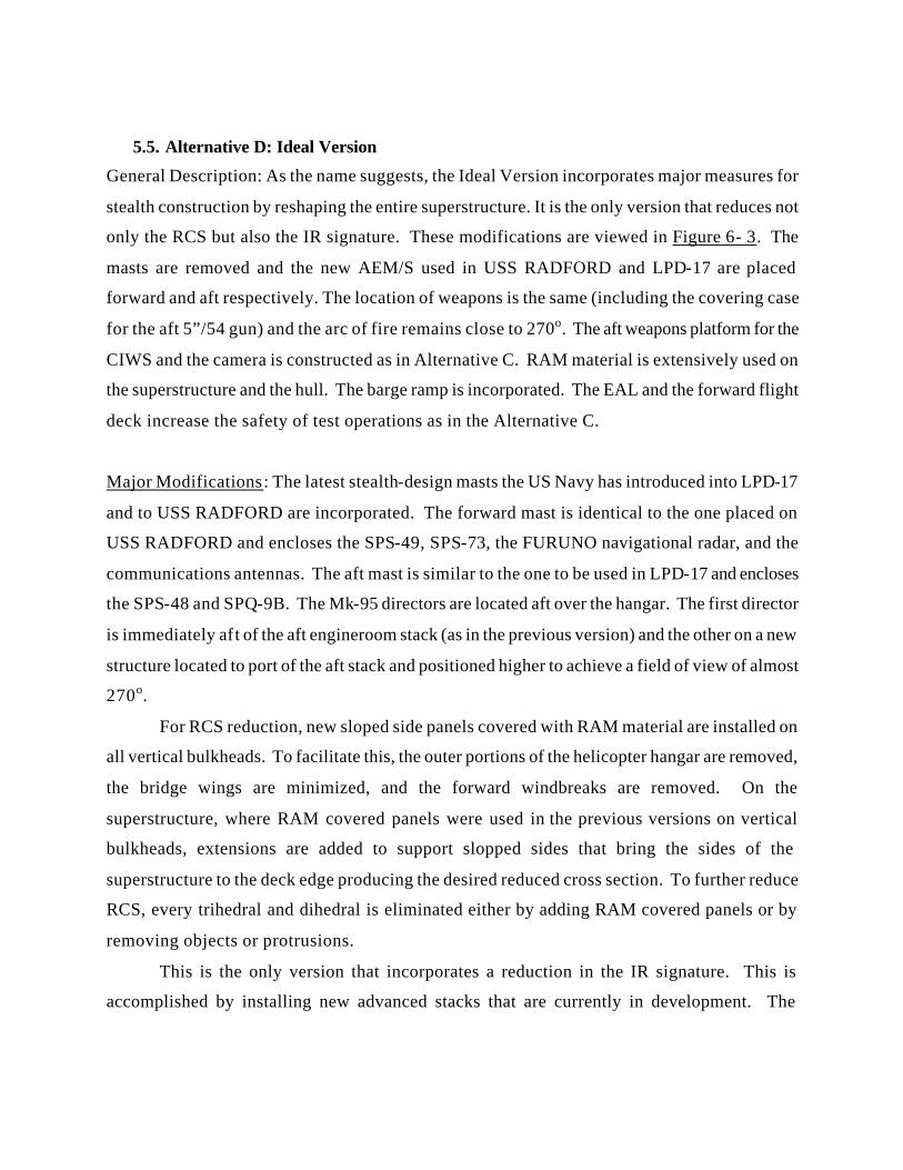
6.5 Alternative D: Ideal Version 6-12
6.6 Radar Cross Section Comparison 6-15
6.7 Field of View Comparison 6-16
6.8 Conclusion of Analysis of Alternatives 6-18
7. Combat Systems Design 7-1
7.1 Payload External Arrangements 7-1
7.1.1 Sensors 7-2
7.1.2 Weapon Systems 7-5
7.1.3 Communications Suite 7-7
7.1.4 Systems Not Accommodated 7-11
7.1.5 Fields of View 7-11
7.2 Installed Systems/Internal Arrangements 7-12
7.2.1 Command And Control Spaces 7-12
7.2.2 Combat Systems Sensor and Weapon Equipment Spaces 7-12
7.2.3 Test Support Spaces 7-13
7.2.4 Expansion Spaces 7-14
7.2.5 Ship Support Spaces 7-15
7.2.6 Spaces Placed in Layup 7-16
7.3 CIC Layout 7-17
7.4 Bridge Layout 7-19
7.5 Ship’s Remote Control System 7-21
7.6 Combat Systems Remote Control System 7-24
7.7 Camera Plan 7-25
7.7.1 Camera Locations 7-25
7.7.2 Camera Control Center 7-26
7.8 Battle Group Interoperability 7-26
7.9 Systems Placed in Lay-up 7-26
8. Radar Cross Section 8-1
8.1 Radar Cross Section of Ex-Decatur and USS O’BRIEN 8-2
8.2 Modifications to the Hull and Superstructure 8-4
8.3 Modifications to the Sensors, Weapons, and Masts 8-5
8.4 Results of RCS Calculations 8-6
8.5 Analysis of Alternatives RCS Calculations 8-6
9. Engineering 9-1
9.1 Propulsion Plant 9-2
9.2 Central Control Station Layout 9-4
9.3 Electric Power Generation and Distribution 9-5
9.4 Services for Weapons and Sensors 9-5
9.5 Test Engineroom 9-5
9.6 Steam to Electric Conversion 9-6
9.6.1 Fresh Water Production 9-6
9.6.2 Chilled Water And HVAC 9-6
9.6.3 Galley and Laundry Equipment 9-7
9.6.4 Fuel and Lube Oil Heating 9-7
9.7 Damage Control 9-8
9.7.1 Damage Control Detection and Surveillance 9-9
9.7.2 Evaluation and Decision 9-11
9.7.3 Engagement 9-12
9.7.4 Stability 9-15
9.8 Corrosion Suppression 9-16
10. Habitability 10-1
10.1 Berthing 10-2
10.2 Crew Recreation and Messing 10-5
10.3 Refuse Strategy 10-7
11 Special Evolutions 11-1
11.1 Flight Operations 11-2
11.1.1 Forward Flight Deck 11-4
11.2 Personnel Transfer 11-7
11.2.1 Enclosed Accommodation Ladder 11-8
11.3 Towing Operations 11-10
11.3.1 Barge Ramp 11-12
11.3.2 Winching System 11-14
11.4 Boat Deck 11-16
11.5 Ammunition Handling 11-18
12. Safety 12-1
13. Integrated Logistics System 13-1
14. Manning 14-1
15. Options 15-1
15.1 Advanced Enclosed Mast/ Sensor System 15-1
15.2 Bridge Wing Reduction 15-4
15.3 Standard Barge Towing Operations 15-6
15.4 Standard Personnel Transfer 15-8
16. Cost 16-1
16.1 Methods to Leverage Cost 16-10
17. Conclusions 17-1
17.1 Requirements Review 17-2
17.2 Areas for Further Research 17-5
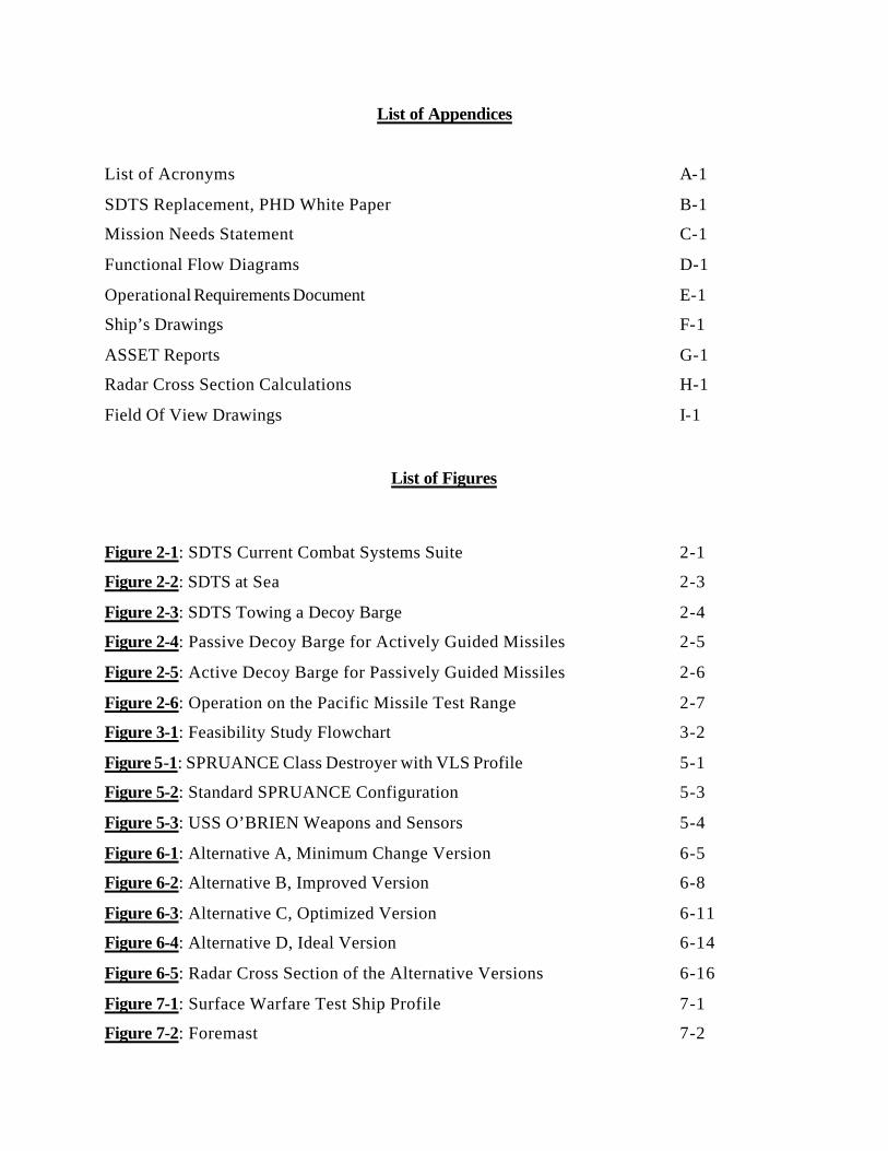
List of Appendices
List of Acronyms A-1
SDTS Replacement, PHD White Paper B-1
Mission Needs Statement C-1
Functional Flow Diagrams D-1
Operational Requirements Document E-1
Ship’s Drawings F-1
ASSET Reports G-1
Radar Cross Section Calculations H-1
Field Of View Drawings I-1
List of Figures
Figure 2-1: SDTS Current Combat Systems Suite 2-1
Figure 2-2: SDTS at Sea 2-3
Figure 2-3: SDTS Towing a Decoy Barge 2-4
Figure 2-4: Passive Decoy Barge for Actively Guided Missiles 2-5
Figure 2-5: Active Decoy Barge for Passively Guided Missiles 2-6
Figure 2-6: Operation on the Pacific Missile Test Range 2-7
Figure 3-1: Feasibility Study Flowchart 3-2
Figure 5-1: SPRUANCE Class Destroyer with VLS Profile 5-1
Figure 5-2: Standard SPRUANCE Configuration 5-3
Figure 5-3: USS O’BRIEN Weapons and Sensors 5-4
Figure 6-1: Alternative A, Minimum Change Version 6-5
Figure 6-2: Alternative B, Improved Version 6-8
Figure 6-3: Alternative C, Optimized Version 6-11
Figure 6-4: Alternative D, Ideal Version 6-14
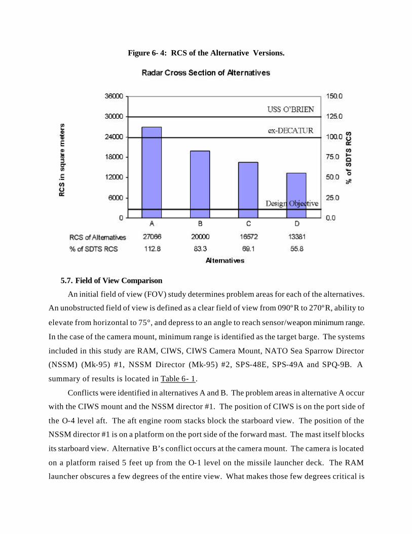
Figure 6-5: Radar Cross Section of the Alternative Versions 6-16
Figure 7-1: Surface Warfare Test Ship Profile 7-1
Figure 7-2: Foremast 7-2
Figure 7-3: Aft Mast 7-4
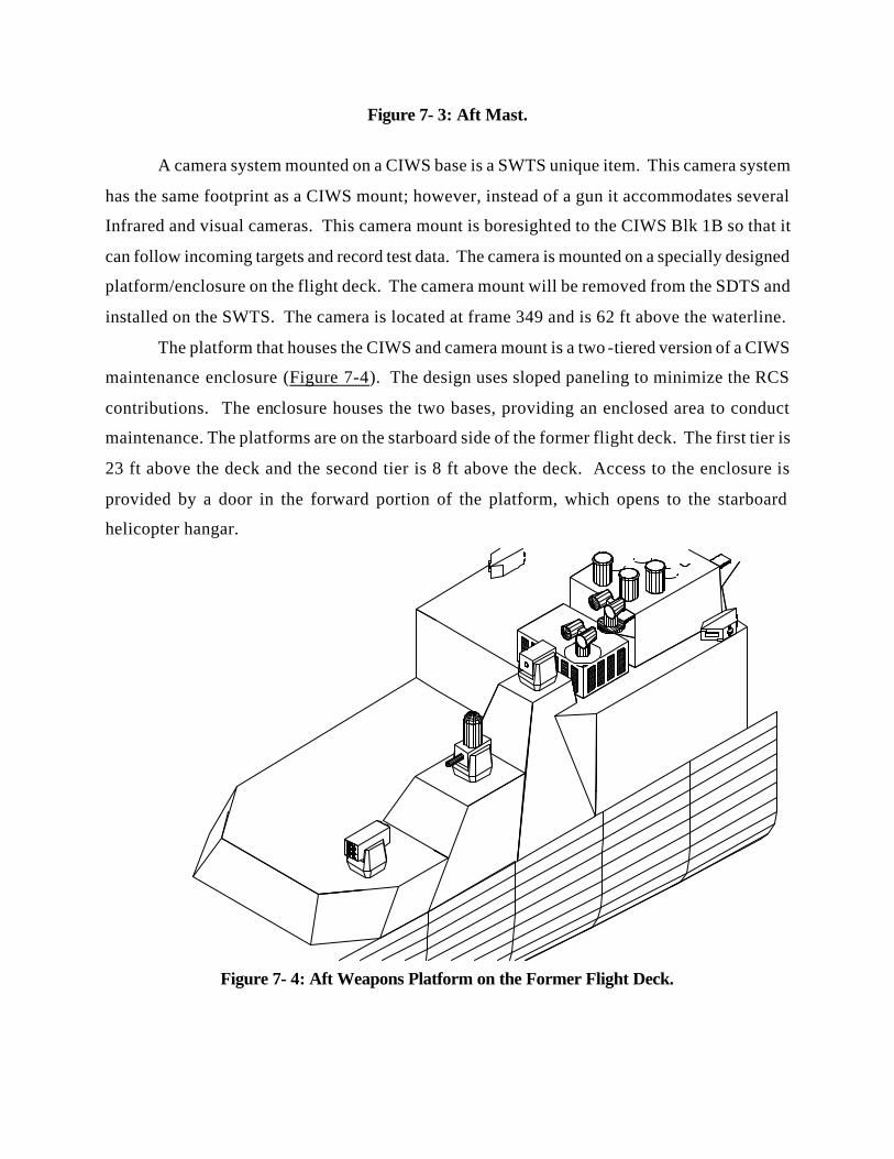
Figure 7-4: Aft Weapons Platform on the Former Flight Deck 7-5
Figure 7-5: Communications Antenna Plan 7-10
Figure 7-6: Typical Field of View Diagram 7-11
Figure 7-7: Combat Information Center Layout 7-18
Figure 7-8: Bridge Layout 7-20
Figure 7-9: Ship’s Remote Control System Internal Interfaces 7-22
Figure 7-10: Ship Control Equipment 7-23
Figure 7-11: Combat Systems Remote Control System 7-24
Figure 8-1: Snell’s Law of Reflection 8-1
Figure 8-2: Reflection in a Dihedral 8-2
Figure 9-1: DD 963 Engineering Spaces 9-1
Figure 9-2: Layout of Engineering Spaces 9-3
Figure 9-3: CCS Layout 9-4
Figure 9-4: DC System Design 9-8
Figure 9-5: TWARSES Display Unit 9-10
Figure 9-6: TWARSES Installed on USS GARY (FFG 51) 9-11
List of Tables Table 3-1: SDTS Order of Battle 3-5
Table 4-1: Prioritized Design Objectives 4-2
Table 5-1: USS O’BRIEN Characteristics 5-2
Table 5-2: SSDS Mk 2 Configuration 5-5
Table 6-1: Field of View Comparison 6-17
Table 7-1: SWTS Communications Suite 7-9
Table 7-2: Command and Control Spaces 7-12
Table 7-3: Sensor and Weapon Support Spaces 7-13
Table 7-4: Test Support Spaces 7-14
Table 7-5: Expansion Spaces 7-14
Table 7-6: Ship Support Spaces 7-15
Table 7-7: Spaces Placed in Lay-Up 7-16
Table 8-1: Hull and Superstructure Directivity Factor 8-3
Table 8-2: Weapons and Sensors Directivity Factor 8-3
Table 9-1: ECSS Components 9-4
Table 9-2: Installed Fire Engagement Systems 9-8
Table 9-3: Stability and Trim Characteristics 9-15
Table 10-1: Berthing Compartment Schedule 10-1
Table 14-1: HM&E Manning 14-1
Table 14-2: Combat Systems Manning 14-2
Table 14-3: Underway Watch Organization 14-3
Table 14-4: Flight Quarters Watchbill 14-4
Table 14-5: Barge Operations Watchbill 14-5
Table 14-6: Small Boat Operations Organization 14-6
Table 16-1: Conversion Cost of USS O’BRIEN ($K) 16-2
Chapter 1: Introduction.
The changing nature of warfare has forced United States Navy ships to operate closer to
land. This littoral warfare exposes ships to a wider variety of threats while compressing the
reaction time against these threats. In response to these increased dangers, the Navy is upgrading
ship self defense weapon systems. The effectiveness of these improved weapon systems must be
verified through realistic testing against real world threats at sea. Fleet downsizing has increased
the demands upon the remaining ships. To reduce the time demands upon these ships, a
dedicated test platform was developed: the Self Defense Test Ship (SDTS).
SDTS is homeported in Port Hueneme, CA, and is operated by Port Hueneme Division,
Naval Surface Warfare Center (PHD NSWC). Since becoming operational in October 1994, it
has successfully tested systems such as Rolling Airframe Missile (RAM) Block I, Close In
Weapon System (CIWS) Block IA and IB, and NATO Seasparrow Missile System (NSSMS)
RIM-7P and RIM-7R. The savings of commissioned warship time and manpower has been
substantial. Additionally, the Test and Evaluation Teams have benefited from possessing a
dedicated test platform with a schedule determined by test requirements rather than ship
operational tempo.
The current SDTS, ex-USS DECATUR (Ex-DDG 31), is more than 45 years old. Recent
hull surveys reveal significant deterioration that requires extensive and expensive repair. The
SDTS cannot transport its own towed targets, incurring added tug expenses. The propulsion
system of the SDTS cannot provide the maximum target speeds desired in some tests. This
limited power precludes testing in moderate sea states. Furthermore, the ship cannot currently
deploy for more than a few days without returning to port, and it cannot deploy to alternate test
sites (such as Barking Sands in Hawaii). The new generation of weapon systems to be tested,
such as Ship Self Defense System (SSDS) Mk 2 and Cooperative Engagement Capability (CEC),
demand more deck space and enclosed volume than the ex-DECATUR can provide. A
replacement for ex-DECATUR that does not suffer from these limitations is urgently needed.
To study the alternatives for the SDTS’ replacement, PHD NSWC has teamed with the
Total Ship Systems Engineering curriculum at the Naval Postgraduate School. Using a systems
engineering approach, the SDTS has been analyzed, the needs have been defined, measurable
requirements have been set, and an Analysis of Alternatives (AOA) has been conducted. The
conclusions of the AOA are the basis for a conceptual design for the SDTS replacement: the
Surface Warfare Test Ship (SWTS). SWTS will have the power, space, and volume to test all of
the ship self defense systems presently under development and be the centerpiece of testing at
Port Hueneme well into the 21st Century.
Naval Surface Warfare Center
PORT HUENEME DIVISION
NAVAL SEA SYSTEMS COMMAND
Chapter 2: Current Capabilities
The use of a dedicated Test and Evaluation (T&E) platform for weapons development has a
long history in the Navy. In the recent past, the USS NORTON SOUND and ex-USS
STODDARD have been used for this purpose. The present dedicated T&E platform is the ex-
DECATUR. In 1987 an Iraqi attack on USS STARK with Exocet anti-ship cruise missiles
resulted in the loss of 37 lives. This incident inspired the ex-DECATUR’s conversion and
employment as a Self Defense Test Ship (SDTS). SDTS is dedicated exclusively to testing ship
self defense weapon systems. It has been instrumental in the development of the Infrared Sensor
System (IRSS), Radiant Mist Infrared Sensor and Tracking System (IRST), Thermal Imaging
Sensor System (TISS), and the SPQ-9B Fire Control Radar.
Prior to the SDTS, commissioned warships tested most weapon systems. These tests were
taxing on the ship and on the weapons engineers. The ship scheduled the installation, testing,
and removal of prototype systems, which distracted from training and maintenance. The test
engineers dealt with the host ship’s spectrum of priorities. The use of a dedicated T&E platform
freed both the engineers and the active Fleet ships from these difficulties.
Figure 2- 1: SDTS Current Combat Systems Suite.
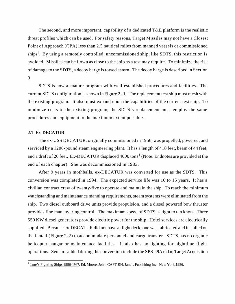
The second, and more important, capability of a dedicated T&E platform is the realistic
threat profiles which can be used. For safety reasons, Target Missiles may not have a Closest
Point of Approach (CPA) less than 2.5 nautical miles from manned vessels or commissioned
ships i. By using a remotely controlled, uncommissioned ship, like SDTS, this restriction is
avoided. Missiles can be flown as close to the ship as a test may require. To minimize the risk
of damage to the SDTS, a decoy barge is towed astern. The decoy barge is described in Section
0
SDTS is now a mature program with well-established procedures and facilities. The
current SDTS configuration is shown in Figure 2- 1. The replacement test ship must mesh with
the existing program. It also must expand upon the capabilities of the current test ship. To
minimize costs to the existing program, the SDTS’s replacement must employ the same
procedures and equipment to the maximum extent possible.
2.1 Ex-DECATUR
The ex-USS DECATUR, originally commissioned in 1956, was propelled, powered, and
serviced by a 1200-pound steam engineering plant. It has a length of 418 feet, beam of 44 feet,
and a draft of 20 feet. Ex-DECATUR displaced 4000 tons1 (Note: Endnotes are provided at the
end of each chapter). She was decommissioned in 1983.
After 9 years in mothballs, ex-DECATUR was converted for use as the SDTS. This
conversion was completed in 1994. The expected service life was 10 to 15 years. It has a
civilian contract crew of twenty-five to operate and maintain the ship. To reach the minimum
watchstanding and maintenance manning requirements, steam systems were eliminated from the
ship. Two diesel outboard drive units provide propulsion, and a diesel powered bow thruster
provides fine maneuvering control. The maximum speed of SDTS is eight to ten knots. Three
550 KW diesel generators provide electric power for the ship. Hotel services are electrically
supplied. Because ex-DECATUR did not have a flight deck, one was fabricated and installed on
the fantail (Figure 2-2) to accommodate personnel and cargo transfer. SDTS has no organic
helicopter hangar or maintenance facilities. It also has no lighting for nighttime flight
operations. Sensors added during the conversion include the SPS-49A radar, Target Acquisition
1 Jane’s Fighting Ships 1986-1987. Ed. Moore, John, CAPT RN. Jane’s Publishing Inc. New York,1986.
System (TAS), and Mk 15 Close in Weapon System (CIWS). The complete arrangement is
shown in Figure 2- 1. Sensors and weapons organic to specific tests have been added as
required. Two remote control systems enable SDTS to conduct unmanned operations: the Ship
Remote Control System (SRCS) and the Combat System Remote Control System (CSRCS).
SDTS is homeported at Port Hueneme and operated by PHD NSWC. It is shown at sea on
the Pacific Missile Test Range in Figure 2- 2. SDTS berths 64 people for up to 30 days and
averages 72 days underway annually. Since SDTS became operational, it has conducted 19
unmanned, at sea, live fire tests and 54 manned firings. In the near future SDTS will test the
High Frequency Surface Wave Radar (HFSWR), Evolved Sea Sparrow Missile System (ESSM),
and additional SPQ-9B testing.
Figure 2- 2: SDTS at Sea.
The small size, high Operational Tempo, and age of SDTS have accelerated the ship’s
problems. Most of the deckspace is occupied. The planned installation of the LPD-17 Ship Self
Defense Systems (SSDS) requires additional space for testing. The limited speed of SDTS (8-10
knots) requires excessive transit time (one calendar day for a one way trip to the OPAREA). The
limited power also prevents SDTS from conducting tests in moderate sea states. This causes
tests to be aborted at government expense due to deteriorated weather conditions after SDTS has
already put to sea. Damage from a HARPOON impact in May 1999 is still being repaired. Most
importantly, recent hull surveys have revealed serious corrosion: 30-40% of the length of the hull
has lost more than half its original hull thickness (Appendix B, page 7). This requires major
repair in the near future. Finally, the fuel tank system was improperly reactivated, resulting in
algae in the tanks and tank seepage. This has led to degraded fuel quality and fuel leakage into
ship’s storerooms. The inherent problems with the SDTS are compelling reasons for the design
of a replacement.
2.2 Decoy Barge
The most realistic test that a self defense system undergoes is the at sea, live fire evaluation.
During such tests, one or more target missiles are fired at the SDTS. The target missile must
present a realistic profile in order to produce a valid test of the self defense system. The missiles
chosen to fly these missions are described in Section 3.4.1. They are actual anti-ship cruise
missiles with telemetry components in place of the warheads. Unfortunately they are still
capable of significant damage from kinetic energy as well as unexpended fuel.
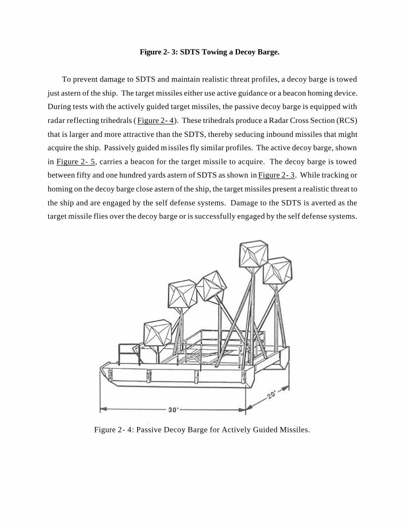
Figure 2- 3: SDTS Towing a Decoy Barge.
To prevent damage to SDTS and maintain realistic threat profiles, a decoy barge is towed
just astern of the ship. The target missiles either use active guidance or a beacon homing device.
During tests with the actively guided target missiles, the passive decoy barge is equipped with
radar reflecting trihedrals ( Figure 2- 4). These trihedrals produce a Radar Cross Section (RCS)
that is larger and more attractive than the SDTS, thereby seducing inbound missiles that might
acquire the ship. Passively guided m issiles fly similar profiles. The active decoy barge, shown
in Figure 2- 5, carries a beacon for the target missile to acquire. The decoy barge is towed
between fifty and one hundred yards astern of SDTS as shown in Figure 2- 3. While tracking or
homing on the decoy barge close astern of the ship, the target missiles present a realistic threat to
the ship and are engaged by the self defense systems. Damage to the SDTS is averted as the
target missile flies over the decoy barge or is successfully engaged by the self defense systems.
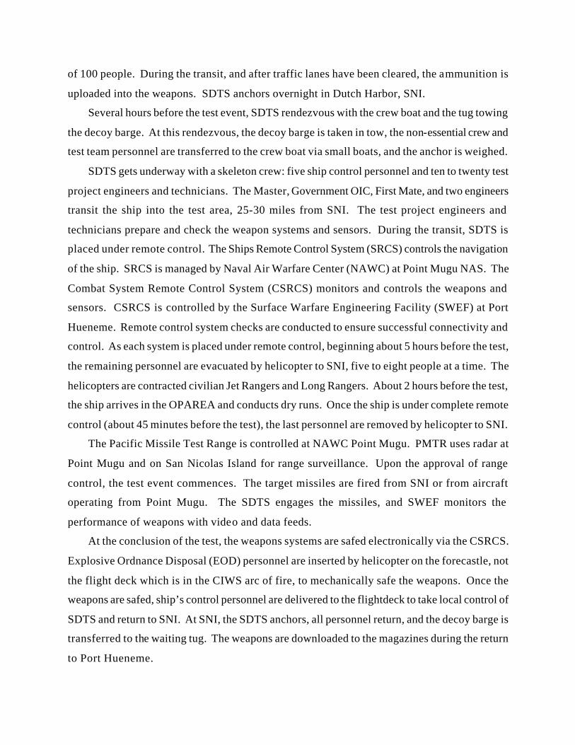
Figure 2- 4: Passive Decoy Barge for Actively Guided Missiles.
The test barges are mounted on pontoons and are 30 feet long, 20 feet wide, with a draft of 2
feet. The displacement is 10,000 pounds. The RCS of the barge is customized for each test
event by setting the number and size of the reflectors. The barge is towed onto the range by a
commercial range tug and taken under tow by SDTS at San Nicolas Island, as explained in the
next section.
Figure 2- 5:Active Decoy Barge for Passively Guided Missiles.
2.3 Test Procedure
The test procedure used for a live fire event is well established. It is an integration of
operators on board SDTS with operators at Point Mugu and Port Hueneme (Figure 2- 6).
Prior to getting underway, the self defense ordnance that will be used during this test is
loaded into the ship’s magazines. SDTS is fueled inport. The decoy barge is left in port to be
towed by a range tug the day of the test.
Figure 2- 6: Operation on the Pacific Missile Test Range.
SDTS has a maximum speed of 10 knots in calm seas. It must transit approximately sixty
nautical miles from Port Hueneme to San Nicolas Island (SNI) in the Pacific Missile Test Range
(PMTR). The ship gets underway one calendar day before the test event with the full test
complement onboard. This complement includes the ships crew, all test event personnel, and
engineers for other onboard systems. The total complement averages 60 people with a maximum
of 100 people. During the transit, and after traffic lanes have been cleared, the ammunition is
uploaded into the weapons. SDTS anchors overnight in Dutch Harbor, SNI.
Several hours before the test event, SDTS rendezvous with the crew boat and the tug towing
the decoy barge. At this rendezvous, the decoy barge is taken in tow, the non-essential crew and
test team personnel are transferred to the crew boat via small boats, and the anchor is weighed.
SDTS gets underway with a skeleton crew: five ship control personnel and ten to twenty test
project engineers and technicians. The Master, Government OIC, First Mate, and two engineers
transit the ship into the test area, 25-30 miles from SNI. The test project engineers and
technicians prepare and check the weapon systems and sensors. During the transit, SDTS is
placed under remote control. The Ships Remote Control System (SRCS) controls the navigation
of the ship. SRCS is managed by Naval Air Warfare Center (NAWC) at Point Mugu NAS. The
Combat System Remote Control System (CSRCS) monitors and controls the weapons and
sensors. CSRCS is controlled by the Surface Warfare Engineering Facility (SWEF) at Port
Hueneme. Remote control system checks are conducted to ensure successful connectivity and
control. As each system is placed under remote control, beginning about 5 hours before the test,
the remaining personnel are evacuated by helicopter to SNI, five to eight people at a time. The
helicopters are contracted civilian Jet Rangers and Long Rangers. About 2 hours before the test,
the ship arrives in the OPAREA and conducts dry runs. Once the ship is under complete remote
control (about 45 minutes before the test), the last personnel are removed by helicopter to SNI.
The Pacific Missile Test Range is controlled at NAWC Point Mugu. PMTR uses radar at
Point Mugu and on San Nicolas Island for range surveillance. Upon the approval of range
control, the test event commences. The target missiles are fired from SNI or from aircraft
operating from Point Mugu. The SDTS engages the missiles, and SWEF monitors the
performance of weapons with video and data feeds.
At the conclusion of the test, the weapons systems are safed electronically via the CSRCS.
Explosive Ordnance Disposal (EOD) personnel are inserted by helicopter on the forecastle, not
the flight deck which is in the CIWS arc of fire, to mechanically safe the weapons. Once the
weapons are safed, ship’s control personnel are delivered to the flightdeck to take local control of
SDTS and return to SNI. At SNI, the SDTS anchors, all personnel return, and the decoy barge is
transferred to the waiting tug. The weapons are downloaded to the magazines during the return
to Port Hueneme.
Chapter 3: Requirements Definition
The ex-DECATUR fills a vital role in the weapons development process. However, it is at
the end of its service life and a replacement is urgently needed. The replacement must provide
all of the capabilities of the ex-DECATUR, but with more space, at higher speeds, and greater
dependability.
The specific shortcomings of ex-DECATUR are:
• UNDERPOWERED- Even mild sea states can cause tests to be canceled at government expense.
• DEGRADED HULL- Significant hull corrosion will make SDTS unseaworthy in the near future.
• INSUFFICIENT VOLUME- The ship lacks space for additional systems and sensors. • INSUFFICIENT BERTHING- Maximum capacity is 60 personnel. Berthing for 150 is
frequently needed.
A Mission Needs Statement (MNS) was developed by PHD NSWC (Appendix C) detailing
the deficiencies of ex-DECATUR and listing new needs for the successor ship. The faculty
modified the MNS to make the design more academically challenging. The design team
translated these needs into design requirements ( Figure 3- 1). The design team utilized a systems
engineering approach to accomplish this task. The first step was to clearly define what was
required in the replacement. This began with describing the system desired by the customer, in
this case PHD NSWC. These needs evolved into a complete set of design parameters in the
Requirements Definition Process. This comprehensive list of “actions” serves as the foundation
for the Operational Requirements Document (ORD). The ORD defines measurable parameters
for each function. Any design that meets the requirements of the ORD can successfully perform
as the SDTS replacement. Beginning with a comprehensive knowledge of the existing system,
the shortcomings were analyzed and the procedures understood. The tasks that the replacement
test ship must perform are captured in the Functional Flow Diagrams (FFD) (Appendix D). The
conflicting tasks were resolved and inter-relationships identified. Different methods for meeting
the requirements are studied in an Analysis of Alternatives (Section 6). One of these
alternatives, actually a hybrid of the alternatives, is fleshed out in the conceptual design.
Figure 3- 1: Feasibility Study Flowchart.
The existing system, the hardware and procedures, has been reviewed in Section 2, and the
shortcomings illustrated. PHD NSWC has defined specific requirements. Based on a study of
existing commissioned hulls conducted by PHD (Appendix B), the SDTS replacement will be a
converted SPRUANCE class destroyer. The decision to convert a DD 963 is based upon the
existing hardware, large volume, and significant propulsive power. The proposed hull is USS
O’BRIEN (DD 975) based upon an anticipated decommissioning date of 2001. The Analysis of
Alternatives will use O’BRIEN as the unmodified hull.
3.1. Mission Needs Statement
In accordance with DoDInst 5000, PHD drafted a Mission Needs Statement. The Mission
Needs Statement (MNS) is the starting point for the system design. It documents the un-met
need of the Navy. In this case, the SDTS needs to be replaced. The MNS identifies the
shortcomings of SDTS. It defines what capabilities are required to solve the deficiency. The
Mission Needs Statement does not suggest a solution, but it does explain what the solution must
be capable of performing.
The capabilities required by the Mission Needs Statement are highlighted here. The entire
MNS is included as Appendix C.
• Sustained speed of 15 knots. • Improved personnel transfer via helicopter and small boat.
• Observable signatures reduced to maximize probability of target homing on towed decoy barge.
• Size and configuration to accomplish simultaneous installation and testing of multiple weapon systems.
• Support future testing of: • Battle Group Interoperability/ BGI System Integration Tests. • Vertical Launch Enhanced Seasparrow Missile • LPD 17 Systems (SSDS Mk II) • DD 21 Related Projects
3.2. Operational Requirements Document
The Operational Requirements Document (ORD) is a strong tool for the design team. The
ORD is derived from the MNS. It defines acceptable Measures of Performance (MOP). This
comprehensive list of MOP’s sets a measurable quantity for every function that the ship must
perform. Any design that fulfills every aspect of the ORD will satisfy the mission of the
replacement test ship. The ORD for the replacement ship is presented in Appendix E.
Acceptable Measures of Performance have two levels: Threshold and Objective.
Threshold parameters are the minimum acceptable performance. Objective parameters are the
best-desired performance. SWTS must meet the threshold requirements. Performance in excess
of the objective parameters is not required and seldom beneficial.
Several of the requirements defined in the Operational Requirements Document had
significant impact on the overall design of the replacement ship. Foremost among these, the
replacement ship shall: (the requirement line numbers from the ORD are listed in parenthesis):
• Be capable of testing many systems currently under production for surface ship installation. (4.a.10)
• Support simultaneous installation of SSDS Mk2, LPD 17 version, plus SPS-49A, and the most limiting system from above (4.a.11).
• Have a Radar Cross Section less than DECATUR (threshold), objective is 10% of DECATUR RCS. (4.a.17)
• Be converted from steam services to electric services. (4.a.26) • Be capable of transferring personnel by boat and helicopter. (4.a.13 and 14) • Provide berthing for 150 personnel for 12 days, including berthing for 12 females. (4.a.18) • Have 15 knot top speed and an endurance of 12 days (4.a.2) • Use one engineroom as an HM&E test platform.(4.a.27)
3.3. Functional Analysis
The ORD describes what the replacement ship must be capable of performing. These
capabilities are top level requirements. The functional analysis describes each function that the
ship must perform in order to support the top-level requirements. For example, if the ship must
be capable of 15 knots (top level requirement), the ship must also be capable of taking on fuel,
lighting off the engines, and getting underway. The product of the Functional Analysis is a
sequence of Functional Flow Diagrams (FFD). These diagrams are included as Appendix D.
The FFD shows relationships of functions. Precursor functions are shown before
subsequent functions. Identifying the functions that the replacement ship must perform defines
the requirements of the ship. Particularly in the case of a conversion, the functions must be well
defined. The existing functions can easily be identified and retained; however, the added
functions must be integrated into the ship. The FFD’s uncovered several additional functions
that the design team needed to add to the ship in order to fulfil the ORD. The functions are
These functions define “what” must be done. “How” the functions are completed is
determined within the Analysis of Alternatives, and the various ways to accomplish the functions
makes each alternative unique . The Operational Requirements Document is the primary
guidance for the ships design. Four alternatives are presented in Section 6 that meet the
requirements set forward in the ORD. Therefore, each is an acceptable alternative from a
performance perspective. Section 6.8 details the conclusions of the AoA. This design review
determines the alternative that is the basis for the Conceptual Design.
The replacement ship is designated the Surface Warfare Test Ship (SWTS).
• Control ship access. • Monitor for fire and flooding electronically. • Provide internal ship Local Area Network. • Deploy and recover the Decoy Barge. • Install the Ship’s Remote Control System and Combat Systems Remote Control
System. • Transfer Personnel Underway via Helicopter and Boat • Reduce Radar Cross Section. • Berth Civilian Crew. • Eliminate Steam Services.
3.4. Threat Analysis
SWTS faces a specific threat: Anti Ship Cruise Missiles (ASCM). It is not expected to
encounter torpedoes, mines, or gunfire. Any requirement to test defensive systems against these
other threats would likely impose requirements on the SWTS in excess of those contained in the
ORD. Presently, PHD NSWC uses seven varieties of ASCM. The SWTS must be optimized to
face any of these threats. A study of the target missiles enables calculations for the required
Fields of View for sensors. Two of the target missiles have active homers. To maximize the
relative signal of the decoy barge to the SWTS, the Radar Cross Section of SWTS must be
minimized at the frequencies of these emitters.
3.4.1. Target Missile Profiles
PHD NSWC uses seven types of ASCM as targets. Because the ASCM is the target of
the Self Defense weapon system that is being tested, it is called the “Target Missile”. The seven
targets are listed in Table 3- 1 ii,iii
Target Harpoon
AGM-84
Vandal
MQM-8G
Vandal
ER
Vandal
EER
Exocet
MM-40
HARM
AGM-88
SETT-8
Midcourse
Flight Profile
Low High
Or Low
High
Or Low
Low
Very
Low
Medium
Terminal
Flight Profile
Sea Skim
or Pop-Up
High Dive
or Skim
High Dive
or Skim
High G
maneuver
Very Low Medium
Guidance Active
Ku Band
Passive Passive Passive Active
I Band
Passive
Speed 0.85 M 2.5 M 2.5 M 2.5 M 0.9 M 0.9 M
Dia. [inch] 13.5 30 30 30 13.7 10
Area [sq in] 143 706 706 706 147 79
Weight [lbs] 1145 4409 4409 4409 1884 798
CL
ASS
IFIE
D
Table 3- 1: SDTS Order of Battle.
These missiles cover the range of current ASCM threats and are representative of current threats
faced by the United States Navy. The targets will not change in the near future. The missiles vary
in size, signature, speed, and flight profile. The flight profiles vary from sea skim, sea skim with
terminal popup, and high dive. The Vandal EER has a high G terminal “jink” designed to confuse
self-defense systems. The targets can be air-launched or launched from San Nicholas Island. The
missiles are fired in salvos as determined by the test requirements. Most salvos are one or two
missiles.
The active seeker frequencies are between 8 and 18 GHz. These are the frequencies of
interest for Radar Cross Section performance evaluation.
Chapter 4: Design Philosophy
The Design Philosophy is a decision-making strategy. It provides a prioritization of design
goals for the entire design team to use. The decision to convert the USS O’BRIEN limited the
scope of the design by defining the hull, superstructure, and engineering plant.
The O’BRIEN has ample room to install any of the systems required by the ORD. The benefit of
spaciousness is offset by the increased Radar Cross Section (RCS). The damage to SDTS caused
by the Harpoon hit in May 1999 placed a high priority on signature reduction.
The mission of O’BRIEN will change from warship to test platform. As a test platform, the
threat will be directed to arrive from aft of the beam. The locations of the weapons and s ensors
can be designed to have unobstructed Fields Of View (FOV) from the aft aspect.
The SWTS must provide a large degree of flexibility to the test engineers. This includes
defining maintenance and meeting areas for the test personnel.
Safe operation of the ship is a vital requirement. This encompasses normal evolutions as
well as evaluating and improving the method for boat and helicopter personnel transfers.
The SWTS will have different berthing standards than a warship. The comfort of the
civilian crew and test personnel as well as the need to provide an on board environment
conducive to creative problem solving requires a change in the current berthing arrangements.
Minimizing the maintenance requirements and manning lessens the operating costs. The
largest impact of this is the removal of steam from the ship and installation of electric services.
The costs will also be leveraged (described in Section 16.1) by providing a test platform for other
types of testing such as a HM&E test engineroom and new underway replenishment equipment.
Because the systems that will be tested will change over time, providing room for future
growth is important. This growth will take the form of additional weapons and sensors. One can
readily anticipate that future self defense systems will be more complex with more components
than current systems.
If a system, such as SONAR, will not be used by SWTS, but the space is not needed for
another purpose, the system will be laid up in place to conserve cost.
This design philosophy is the basis for design trade off decisions to maximize the SWTS’s
performance as a whole platform. The complete list of priorities is given as Table 4-1.
Table 4-1: Prioritized Design Objectives.
Design Philosophy 1. Radar Cross Section Reduction 2. Large Field of Views 3. Test Flexibility 4. Safety 5. System and Sensor Flexibility 6. Ability to test widest range of systems 7. Accessibility to systems and sensors for maintenance/installation/removal 8. Room for Future Growth 9. Minimum Manning 10. HM&E Testing 11. Comfort of Crew and Riders 12. Redundancy 13. Survivability 14. Minimum Modifications 15. Low cost 16. Battle Group Interoperability 17. Recommisionable
Chapter 5: Projected Capabilities
The SWTS will replace SDTS, but the remaining infrastructure of PHD and PMTR will
not change. SWTS must integrate easily into these existing programs. The SWTS must function
with the decoy barge, helicopters, and boats currently used on the range. The first system that
will be tested is the Ship Self-Defense System (SSDS). Many of the SSDS sensors will remain
on board the SWTS after SSDS is completed.
5.1. SPRUANCE Class Destroyer
The proposed hull for the SWTS conversion is USS O’BRIEN (DD 975). O’BRIEN is
scheduled to decommission in 2001. Like all SPRUANCE hulls, O’BRIEN was designed as an
anti-submarine warfare ship, and the strike capability was added later. It is not equipped for anti-
air warfare. O’BRIEN has an aluminum superstructure, and the Bridge and Combat Information
Center (CIC) are spacious. It has been modified to carry two SH-60B helicopters in its hangar
with twin Recovery, Assist, Secure, and Traverse (RAST) tracks. The specifics of the
O’BRIEN’s hull are listed in Table 5- 1 and the topside arrangement is shown as Error!
Reference source not found..
Figure 5- 1: SPRUANCE Class Destroyer with VLS Profile.
Table 5- 1: USS O’BRIEN Characteristics.
Length…………………………………………………………………………563 feet Beam .............................55 feet Displacement .....................8,200 tons Draft.............................30' 6; forward, 20' 6"aft Armament..........................two 5-inch 54 caliber LWG two Mk 15 20 mm CIWS two triple-tube torpedo launchers Mk 29 NATO Seasparrow Missile System Harpoon Cruise Missile System Mk 41 Vertical Launch System Aircraft .........................2 SH-60B Helicopters Propulsion .......................4 General Electric LM 2500 gas turbines total of 80,000 shaft horsepower Speed ............................30+ knots Complement .......................22 Officers 22 Chief Petty Officers 320 Enlisted Date Launched.....................17 July 1976 Date Commissioned.................3 December 1977
5.2. Payload
The O’BRIEN is a SPRUANCE Class Destroyer with the Vertical Launch System (VLS).
The configuration of the O’BRIEN is shown as Figure 5- 2. The O’BRIEN has two Mk 45 five
inch 54 caliber Light Weight Guns. The forward 5” gun is Mount 51; the aft is Mount 52. The
two CIWS mounts are named similarly: Mount 21 is installed on the 04 level forward, starboard
side; Mount 22 is installed on the 04 level aft, port side. The Harpoon missiles are mounted on
the 03 level midships on the “Harpoon Deck.” The Mk 91 NATO Seasparrow Missile System
(SWY-1) is Mod 0, so there is only one Mk 95 director installed. The Mk 29 NATO Seasparrow
Missile Launcher is on the “Missile Deck,” the 01 level aft of the flight deck. O’BRIEN has a 61
cell Mk 41 VLS launcher on the forecastle.
Figure 5- 2: USS O'BRIEN Weapons and Sensors.
The O’BRIEN possesses significantly more deck space and internal volume than the
DECATUR possesses. All of the systems presently installed on DECATUR will easily fit on
O’BRIEN. The major internal arrangements challenge is the Ship Self-Defense System (SSDS)
as configured for LPD-17 (SSDS Mk 2 Mod 2). Table 5- 2 lists the requirements of this system.
PHD NSWC has additionally requested that an SPS-49A radar and CIWS Block 1B be installed.
A camera mounted on a CIWS pedestal monitors inbound targets and r ecords the engagement of
those targets. This “CIWS Camera Mount” must be located near the CIWS and boresighted to
the CIWS mount to minimize parallax errors.
A second Mk 91 NSSMS director must be added to meet the SSDS Mk 2 Mod 2
requirements. Although SSDS does not require a five -inch gun, one will be retained for possible
future testing.
Table 5- 2: SSDS Mk 2 Mod 2 Configuration and USS O’BRIEN’s Combat Systems Suite.
5.3. Berthing
The SPRUANCE is designed for a crew of 22 Officers, 22 CPOs, and 320 enlisted. The entire
SPRUANCE class has been modified for integrated (co-ed) crews. The Officer’s berthing has
thirteen staterooms and a CO’s inport and at sea cabins. CPO berthing is split for nineteen males
and three females. The crew berths in six spaces with between twenty-four and seventy-two
bunks in standard Navy three rack tiers. Each berthing space has a dedicated shower room and
head. Only the CO’s cabins and the XO’s stateroom have a private head and shower.
5.4. Hull, Mechanical and Electrical
The O’BRIEN’s engineering plant consists of two engine rooms and three auxiliary machinery
rooms. Each Engine Room has two Gas Turbine Engines for propulsion and one Gas Turbine
Generator (GTG) for electric power. A third GTG is located on the starboard side of the second
LPD 17 Configuration USS O’BRIEN (DD 975) Configuration Detect
The CIWS mounts 21 and 22 on the O’BRIEN are removed and the CIWS from the SDTS is
transferred. The new mount is installed on the lower tier of the flight deck weapons platform at
frame 368, 48 ft above the waterline.
The Mk 45 5”/54 is a single barrel automatic multi-purpose gun. On the SPRUANCE class, this
mount is used for air and surface engagements as well as fire support for forces ashore. The USS
O’BRIEN has two mounts; one on the forecastle and the other on the fantail. The forward mount
was removed to make space for the flight deck and the aft gun mount was retained for future
munitions testing and surface fire missions.
The SPRUANCE class has 64 Mk 41 VLS B/L III cells used for Tomahawks. In the future, the
Evolved NATO Sea Sparrow Missile (ESSM) will be added to that inventory. The SWTS will be
used to test self-defense weapons; so it will not require the capability to launch Standard Missile or
Tomahawk. The SWTS does not require all 64 cells. Six of the 8 modules are laid up. The
remaining 16 cells, System Module (A7) and Standard Module (A8) are converted to VLS B/L VII
to fire ESSM. No changes are required for the ship services provided to VLS such as HVAC,
electrical, water and air.
Evolved Seasparrow Missile (ESSM) is the next generation of self-defense missile system to be
developed from the NATO Seasparrow Missile System. It uses a semi-active RF seeker with
midcourse guidance. ESSM is designed to engage faster, lower, smaller and more maneuverable
anti-ship cruise missiles. Improvements from the RIM-7M/P include higher speed (Mach 2.0),
increased maneuverability (>30g), a new warhead, and a smaller radar cross section. One
significant advantage is the extended range. ESSM triples the NSSM range to 24 nm, expanding
the self-defense envelope of the ship. ESSM is packaged in quad-packs that are compatible with
the Mk 41 VLS system.
The ESSM fire control system for SWTS is the Re-architectured NATO Seasparrow Missile
System (RNSSMS). The RNSSMS is an upgrade to the standard NSSMS. It takes advantage of
current technology by replacing the analog circuits with digital circuits and using fiber optics to
connect each part of the system. The integration of ESSM with the RNSSMS is not completed and
provisions will be required before ESSM can be tested from this platform.
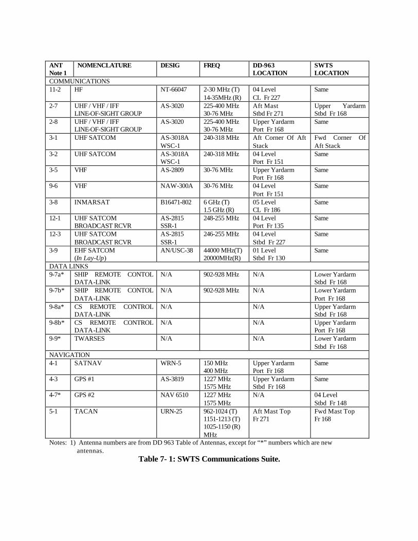
1.9.3. Communications Suite
SWTS maintains three groups of antennas for the conduct of its test mission:
1) Voice and Data Communications: For normal underway operations and during periods of Battle Group Interoperability, SWTS mounts a reduced DD 963 comms suite that includes: a) 1 HF voice antenna
b) 4 VHF line-of-sight voice antennas c) 2 UHF line-of-sight voice antennas d) INMARSAT satellite voice antenna e) UHF satellite voice and data antenna set f) UHF satellite broadcast receiver antenna set g) EHF satellite voice and data antenna (laid-up)
2) Data Links: Primarily employed to control SWTS during unmanned, remote operation at sea, the Ship Remote Control and Combat Systems Remote Control links are served by two antennas each for full azimuth coverage. This also includes the ship wide remote sensing system, TWARSES.
3) Navigation: Includes one SATNAV and two GPS satellite navigation receivers. The TACAN antenna for control of aircraft is also described.
Each antenna has the appropriate transceiver and antenna coupler retained. Most of these
components are located in the Radio Transmitter Room on the 03 level.
Table 7-1 identifies the antenna groups with their designated locations aboard SWTS.
The design endeavored to keep original DD 963 antennas in place to reduce conversion costs.
Location changes are indicated in the table.
Figure 7-5 shows the antenna mounting arrangement for SWTS. Antenna numbers are
cross-referenced to the table and maintain the original DD 963 antenna numbers except where
indicated.
An EMI survey/analysis has not been conducted on this antenna arrangement, as
discussed in Section 17.3.
ANT Note 1
NOMENCLATURE DESIG FREQ DD-963 LOCATION
SWTS LOCATION
COMMUNICATIONS 11-2 HF NT-66047 2-30 MHz (T)
14-35MHz (R) 04 Level CL Fr 227
Same
2-7 UHF / VHF / IFF LINE-OF-SIGHT GROUP
AS-3020 225-400 MHz 30-76 MHz
Aft Mast Stbd Fr 271
Upper Yardarm Stbd Fr 168
2-8 UHF / VHF / IFF LINE-OF-SIGHT GROUP
AS-3020 225-400 MHz 30-76 MHz
Upper Yardarm Port Fr 168
Same
3-1 UHF SATCOM AS-3018A WSC-1
240-318 MHz Aft Corner Of Aft Stack
Fwd Corner Of Aft Stack
3-2 UHF SATCOM AS-3018A WSC-1
240-318 MHz 04 Level Port Fr 151
Same
3-5 VHF AS-2809 30-76 MHz Upper Yardarm Port Fr 168
Notes: 1) Antenna numbers are from DD 963 Table of Antennas, except for “*” numbers which are new antennas.
Table 7- 1: SWTS Communications Suite.
Figure 7- 5: Communications Antenna Plan.
5.2. Systems Not Accommodated All systems required by the Operational Requirements Document (ORD) have been
successfully accommodated. Two systems identified as possible future payloads, the High
Energy Laser (HEL) and the Multi-Function Radar (MFR), may provide challenges in terms of
electrical power and space accommodation, however, hard data is not available at this time.
2.1.1. Fields of View A detailed study of the fields of view and firing arcs for each system shows that all systems
are clear from beam to beam. The AUTOCAD solid model of the SWTS is ray traced to produce
Field of View diagrams. Figure 7- 6 is a sample Mercator coverage diagram showing the
blockage of equipment and structures. Appendix I contains Field of View Diagrams for all
weapons and sensors.
RAM Blk 1 FOV
-40
-20
0
20
40
60
80
100
0 21 42 63 84 105
126
147
168
189
210
231
252
273
294
315
336
357
Bearing (Relative)
Ele
vati
on
An
gle
Figure 7- 6: Typical Field of View Diagram.
5.2. Internal Arrangements
A design philosophy for internal arrangement was set as follows:
a) Retain required-function spaces in an unmodified state to reduce conversion costs. b) Spaces with a function no longer required with a large amount of equipment are laid-
up and locked. c) Spaces with a function no longer required with a small amount of equipment are
stripped and identified as expansion spaces. d) Similar function spaces are grouped together whenever possible. e) Support equipment spaces are placed as near as possible to supported equipment. f) Data Collection Rooms are placed throughout the ship to support testing of various
systems and processes. g) Personnel, stores, and equipment movement are minimized. h) Laborsaving devices are retained where beneficial in supporting minimum manning.
5.3. Command and Control Spaces
The primary control space for ship operations, combat systems employment, and test
coordination is the Combat Information Center (Section 5.8.5.1). Ship piloting, at-sea routine
and helicopter control are conducted from the bridge (Section 5.8.5.2). Engineering and damage
control are conducted from the Central Control Station (Section 9.2). Table 7-2 identifies SWTS
command and control spaces:
Space Compt Num. Modifications (summary) Former Function CIC 02-139-0-C Remove OJ consoles
Lay-up TWCS, GFCS Add SSDS consoles Add Test Coord Area
Same
Bridge 03-140-0-C Add TWARSES, SRCS Add Furuno radar display Lay-up OJ console Add 4 life rafts on wings
Same
Central Control Station 2-272-0-C Add TWARSES Add SRCS
Same
Table 7- 2: Command and Control Spaces. 5.4. Combat System Sensor and Weapon Equipment Spaces
Large spaces no longer needed for the SWTS mission are converted to support the larger
array of sensors to be fitted. The following table identifies SWTS sensor and weapon support
spaces:
Space Compt Num.
Modifications (summary) Former Function
EW Cooling Equip Rm 04-292-2-Q Add cooling equipment TAS Fan Room EW Local Control Equip Rm
SPS-49A Cooling Equip Rm 02-267-2-Q Add cooling equipment Helo Det office CIWS Magazine 02-281-2-M N/A Torpedo Magazine Weapons Maintenance Rm 02-276-0-Q N/A Helo Repair Shop RAM Maintenance Locker 02-346-1-Q New structure N/A CIWS Maintenance Locker 02-366-1-Q New structure N/A Data Processing Center 01-138-0-C N/A Same Elect CW Equip Room 01-206-01-Q N/A Same Main Magazine 01-398-0-M N/A NSSMS magazine RAM Equipment Room 01-398-1-A
w/ UNREP Sta Remove UNREP station bulkhead Add RAM equipment
UNREP Gear Locker UNREP Station
Mk 41 VLS 1-94-0-Q Lay-up 6 of 8 modules Same MK 41 Support Equip Rm 1-130-0-Q N/A Same Gyro Room #1 2-128-0-Q N/A Same IC/Gyro Room #1 3-128-0-Q N/A Same IC/Gyro Room #2 3-382-0-Q N/A Same
Table 7- 3: Sensor/Weapon Support Spaces. 5.5. Test Support Spaces
Test support spaces directly contribute to the conduct and evaluation of any test
performed by the SWTS. Primary control and coordination of tests is carried out in CIC. Data
Collection Rooms (DCRs) are outfitted with work tables and chairs, ample electrical outlets,
cable tubes to adjacent spaces, and atmospheric controls. These rooms will allow Navy and
industry technicians to effectively acquire test data without interfering with equipment or
personnel processes. The layout of the Special Projects Space is described in Section 5.8.5.1.
The following table identifies SWTS test support spaces:
Space Compt Num Modifications (summary) Former Function Data Collection Rm #1 03-291-0-C Add DCR mods Bosun Office Data Collection Rm #2 02-174-1-C Add DCR mods CIC Admin Test Control and Coordination Area
02-139-0-C Add Test Director position Add Test Coord Console
CIC
(within CIC) Add Camera Control Console Special Projects Rm 02-139-2-C See Section 7.3 Sonar Control Data Collection Rm #3 01-178-1-Q Add DCR mods Elect Repair Shop Conference Room 01-265-0-C Add chairs
Add display system Add computer work desks
Wardroom
Data Collection Rm #4 01-382-0-Q Remove RAST equipment Add DCR mods
RAST Equipment Rm
Data Collection Rm #5 2-464-2-Q Add DCR mods Small Arms locker Engineering Data Collection Rm
2-261-1-Q Add DCR mods Supply Office
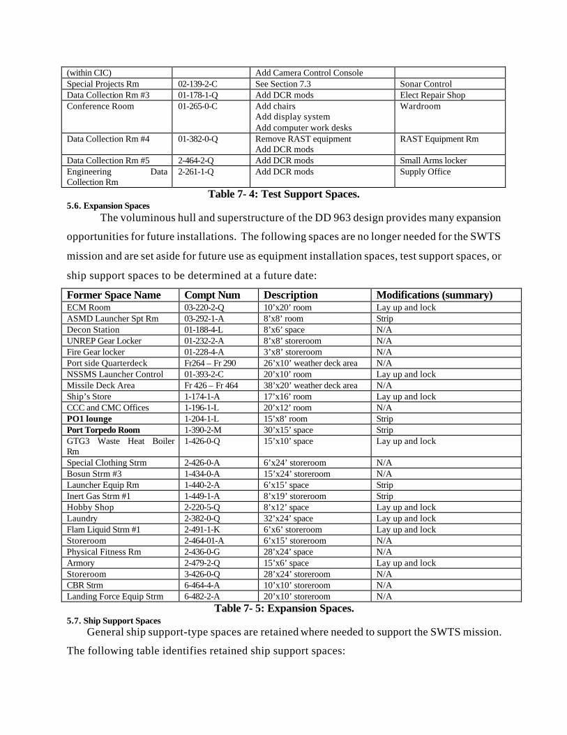
Table 7- 4: Test Support Spaces. 5.6. Expansion Spaces
The voluminous hull and superstructure of the DD 963 design provides many expansion
opportunities for future installations. The following spaces are no longer needed for the SWTS
mission and are set aside for future use as equipment installation spaces, test support spaces, or
ship support spaces to be determined at a future date:
Former Space Name Compt Num Description Modifications (summary) ECM Room 03-220-2-Q 10’x20’ room Lay up and lock ASMD Launcher Spt Rm 03-292-1-A 8’x8’ room Strip Decon Station 01-188-4-L 8’x6’ space N/A UNREP Gear Locker 01-232-2-A 8’x8’ storeroom N/A Fire Gear locker 01-228-4-A 3’x8’ storeroom N/A Port side Quarterdeck Fr264 – Fr 290 26’x10’ weather deck area N/A NSSMS Launcher Control 01-393-2-C 20’x10’ room Lay up and lock Missile Deck Area Fr 426 – Fr 464 38’x20’ weather deck area N/A Ship’s Store 1-174-1-A 17’x16’ room Lay up and lock CCC and CMC Offices 1-196-1-L 20’x12’ room N/A PO1 lounge 1-204-1-L 15’x8’ room Strip Port Torpedo Room 1-390-2-M 30’x15’ space Strip GTG3 Waste Heat Boiler Rm
1-426-0-Q 15’x10’ space Lay up and lock
Special Clothing Strm 2-426-0-A 6’x24’ storeroom N/A Bosun Strm #3 1-434-0-A 15’x24’ storeroom N/A Launcher Equip Rm 1-440-2-A 6’x15’ space Strip Inert Gas Strm #1 1-449-1-A 8’x19’ storeroom Strip Hobby Shop 2-220-5-Q 8’x12’ space Lay up and lock Laundry 2-382-0-Q 32’x24’ space Lay up and lock Flam Liquid Strm #1 2-491-1-K 6’x6’ storeroom Lay up and lock Storeroom 2-464-01-A 6’x15’ storeroom N/A Physical Fitness Rm 2-436-0-G 28’x24’ space N/A Armory 2-479-2-Q 15’x6’ space Lay up and lock Storeroom 3-426-0-Q 28’x24’ storeroom N/A CBR Strm 6-464-4-A 10’x10’ storeroom N/A Landing Force Equip Strm 6-482-2-A 20’x10’ storeroom N/A
Table 7- 5: Expansion Spaces. 5.7. Ship Support Spaces
General ship support-type spaces are retained where needed to support the SWTS mission.
The following table identifies retained ship support spaces:
Space Name Compt Num Modifications (summary) Former Function Quarter Deck 01-236-01-L N/A Same Rider Lounge 01-270-0-L N/A Wardroom lounge Windlass Room 1-0-0-E N/A Same Combat Systems Office 1-138-1-Q N/A Weapons Dept Office Test Directors Office 1-138-2-Q N/A Ships Office Ships Admin Office 1-154-1-Q N/A Dispersing Office Deck Dept Office 1-162-1-Q N/A Operations Dept Office Tech Library 1-159-0-Q N/A Same Crew lounge 1-248-1-L
1-260-1-L N/A CPO Lounge
CPO Mess Medical treatment Room 1-382-0-L N/A Same Sickbay 1-398-0-L N/A Same Medical Strm 1-406-0-A N/A Same Stewards Linen Locker 1-412-0-Q Remove barber equipment Barber shop Laundry 1-390-1-M Remove torpedo gear
See Section 11.2 Fan room Store room Filter Cleaning shop
Paint Mix and Issue 1-457-0-K N/A Same Inert gas Storeroom 1-460-1-A N/A Same Rider Office Complex 2-149-0-L Remove racks and lockers
Add 18 desks and lockers Crew Berthing
Engineering Dept Office 2-260-0-Q N/A Same Machine and welding Shop
2-387-01-Q N/A Same
Hull Workshop 2-414-0-Q N/A Same Tool Issue 2-394-2-Q N/A Same Electrical Work shop 2-404-2-Q N/A Same Flam Liquids Strm #1 2-491-1-Q N/A Same Line Locker 2-506-3-A N/A Same Line Locker 2-506-2-Q Remove bathy equipment
Add mooring line reels Bathy Equip Room
Supply Office 3-283-0-Q N/A Supply Support Center Supply Storeroom #1 3-260-01-A N/A Same Supply Storeroom #2 3-283-2-A N/A Same Engineering Storeroom 3-382-2-A N/A Supply Dept storeroom Mooring Line Storeroom 6-488-1-A N/A Same
Table 7- 6: Ship Support Spaces. 5.8. Spaces Placed in Lay-Up
Spaces not needed to support the SWTS mission are placed in lay-up and secured (locked).
The following table identifies spaces placed in lay-up:
Space Name Compt Number Signal Shack 04-162-0-C Landing Control Station 03-332-2-Q RAST tracks Former flight deck Wardroom Pantry 01-260-0-L Sonar Equipment Room #1 1-28-01-Q
MT 51 Loader Drum Room 1-58-01-M Elevator Machinery Room 1-82-1-Q Decon Station #1 1-434-2-L Fwd Ammo Elevator 3-82-0-T Torpedo Elevator Fr 418 Aft Ammo Elevator 3-464-0-T Sonar Equipment Room #2 2-28-01-Q Fwd Ammo Pallet Staging 2-58-01-Q Entertainment Equipment Rm 2-236-1-A Main Engine Room #2 5-300-0-E Trash Compactor Room 2-382-4-Q Aft Ammo Pallet Staging 2-464-01-A MT 52 Loader Drum Room 2-482-0-M Sonar Equipment Room #3 3-28-01-Q MT 51 Projectile Magazine 3-62-01-M MT 51 Powder Magazine 3-76-1-M
The SWTS Combat Information Center is the nerve center for sensor and weapon
employment and test control. Figure 7 -7 lays out of the new SWTS CIC. Initially, the primary
system to be tested is the SSDS Mk2. The SSDS console in development, with positions for the
TAO and two operators, is fitted in front of two rear-projection large screen displays (LSDs).
Behind the SSDS console is the test control group consisting of the test director’s position, a
comms console for two test control/coordination personnel and the remote camera control
console. Other changes to the original O’BRIEN CIC include:
a) Addition of CIWS Block 1B console. b) Rearchitectured NSSMS consoles (from ex-DECATUR). c) Removal of several operations consoles including the MT 51 gun console. MT 52
Console and Gun Control Console (GCC) are laid-up. d) Lay-up of the Tomahawk Weapon Control System. e) Lay-up of one of four OJ-type tracker consoles. f) CIC Admin is converted to Data Collection Room #2 to support monitoring/testing of
equipment and events in CIC. Special Projects Room: This space will support high-level classified tests and data
acquisition. To support this mission, a SCIF-type space is arranged with the necessary security
features, including a vault. Optimally located adjacent to CIC, the former Sonar Control space is
stripped of all console and sonar related equipment. Room for Special Project equipment is
provided to port and a table for workstations is provided to starboard. A classified
planning/briefing table is included. This space is an extended form of the Data Collection
Rooms found through out the SWTS.
Figure 7- 7: Combat Information Center Layout.
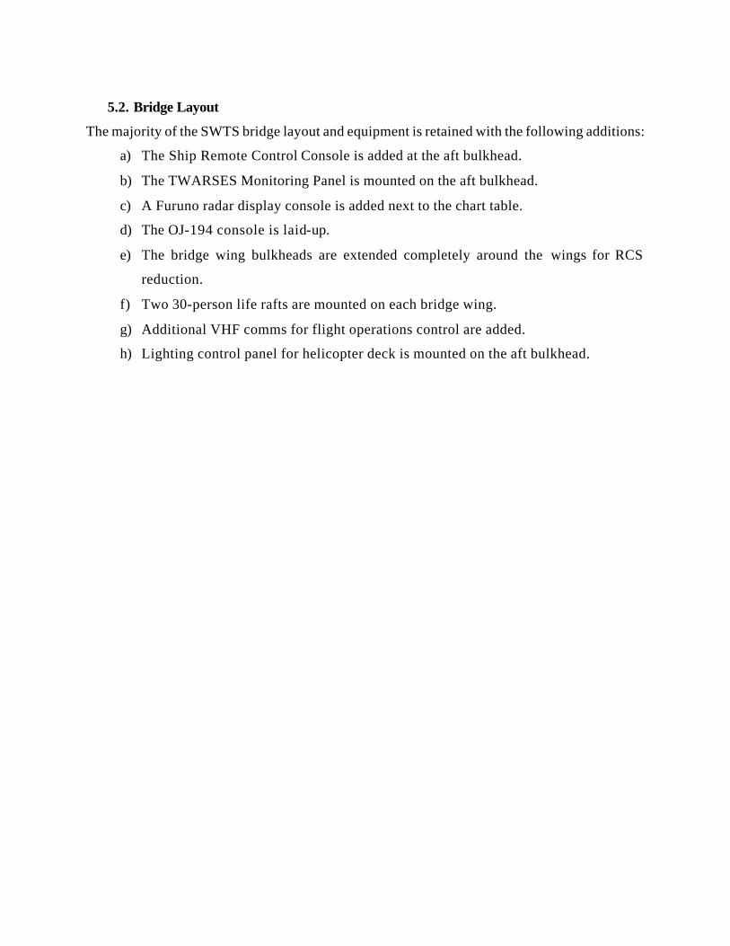
5.2. Bridge Layout
The majority of the SWTS bridge layout and equipment is retained with the following additions:
a) The Ship Remote Control Console is added at the aft bulkhead.
b) The TWARSES Monitoring Panel is mounted on the aft bulkhead.
c) A Furuno radar display console is added next to the chart table.
d) The OJ-194 console is laid-up.
e) The bridge wing bulkheads are extended completely around the wings for RCS
reduction.
f) Two 30-person life rafts are mounted on each bridge wing.
g) Additional VHF comms for flight operations control are added.
h) Lighting control panel for helicopter deck is mounted on the aft bulkhead.
Figure 7- 8: Bridge Layout.
5.9.Ship’s Remote Control System
During unmanned operations, two remote control systems control and monitor SWTS.
The Combat Systems Remote Control System (CSRCS) controls the combat system weapons
and sensors. The Ship’s Remote Control System (SRCS) controls all remaining aspects of the
ship. As described in Section 2.3, NAWC at NAS Point Mugu controls SWTS while the ship is
on the range. The specific functions that must be controlled and monitored are navigation,
damage control, and engineering. Two major evolutions occur while the SWTS is unmanned:
flight operations for personnel transfer and the test event. The SRCS must provide control
during these operations. The system also provides a “Kill Switch” designed to shut down the
GTGs in the event of an emergency. The ship will go dead in the water. Remote monitoring can
still be performed via TWARSES and SRCS.
The Surface Targets Division at NAWC installs and maintains the SRCS. The system
presently in use on the SDTS is the analog Integrated Target Control System (ITCS). A
workstation on the bridge controls the functions of the ship and interfaces with the operators via
an RF data link. Controller Area Networks (CANs) integrate and control the ship’s systems.
Although the ITCS has not been installed on any system as complex as the O’BRIEN, the system
is modular and can be scaled for use on the SWTS. It will be digital to allow testing on any
range.
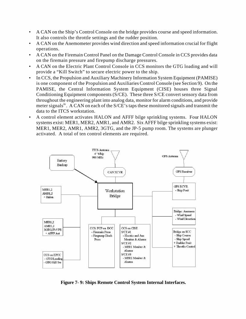
The installed ITCS network is shown in Figure 7.9. CAN’s are shown as square boxes,
receivers and transceivers are shown as octagons, antennae are shown as triangles (apex down),
and the central workstation is shown as a heavy box in the center of the diagram. The first line
shows the location by space and console. The following lines show the parameter that is
controlled or monitored. A control function is denoted by “+“ while a monitored parameter is
denoted by “-“
The central workstation is a standard Industrial PC that is installed on the bridge as
shown in Figure 7-8. The workstation has two way communications with Point Mugu via a
digital RF data link. Three link options exist for the SWTS application. The most likely
arrangement is two 4-foot whip antennas operating at 902 MHz.
The CAN nodes are 11”x4”x4”. CAN’s are installed on the following equipment:
• A CAN on the GPS receiver provides ship’s position information.
• A CAN on the Ship’s Control Console on the bridge provides course and speed information. It also controls the throttle settings and the rudder position.
• A CAN on the Anemometer provides wind direction and speed information crucial for flight operations.
• A CAN on the Firemain Control Panel on the Damage Control Console in CCS provides data on the firemain pressure and firepump discharge pressures.
• A CAN on the Electric Plant Control Console in CCS monitors the GTG loading and will provide a “Kill Switch” to secure electric power to the ship.
• In CCS, the Propulsion and Auxiliary Machinery Information System Equipment (PAMISE) is one component of the Propulsion and Auxiliaries Control Console (see Section 9). On the PAMISE, the Central Information System Equipment (CISE) houses three Signal Conditioning Equipment components (S/CE). These three S/CE convert sensory data from throughout the engineering plant into analog data, monitor for alarm conditions, and provide meter signalsiv. A CAN on each of the S/CE’s taps these monitored signals and transmit the data to the ITCS workstation.
• A control element activates HALON and AFFF bilge sprinkling systems. Four HALON systems exist: MER1, MER2, AMR1, and AMR2. Six AFFF bilge sprinkling systems exist: MER1, MER2, AMR1, AMR2, 3GTG, and the JP-5 pump room. The systems are plunger activated. A total of ten control elements are required.
Figure 7- 9: Ships Remote Control System Internal Interfaces.
The CPU on the bridge records all of the data that SRCS receives in a digital “Session
Log.” Any of this data may be selected for transmission on the data link, but to maintain the
speed of the SRCS datalink, most data is sent on request. Alarms and warning information are
always sent as soon as SRCS receives the signal. Vital data such as ships position, course and
speed, and rudder position are also continuously transmitted.
A battery backup for the remote control system is installed to provide four hours of
uninterrupted power (ITCS UPS) for the workstation, GPS receiver, and ITCS Transceiver. Four
hours provides ample time for emergency response personnel to arrive on the ship, conduct
initial damage control, and restore the ship to manned operations. The Uninterrupted Power
Supply in CCS provides power to the EPCC and PACC. These consoles can monitor and control
the engineering spaces. TWARSES has a battery backup that continues to supply damage
control information to the ITCS. The ITCS UPS enables the engineering plant, damage control,
and ship’s position information to the ship’s controllers. This information will be crucial for the
emergency response personnel.
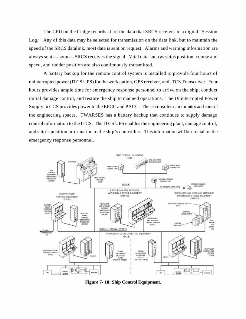
Figure 7- 10: Ship Control Equipment.
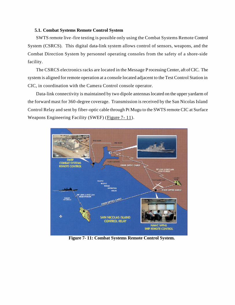
5.1. Combat Systems Remote Control System
SWTS remote live -fire testing is possible only using the Combat Systems Remote Control
System (CSRCS). This digital data-link system allows control of sensors, weapons, and the
Combat Direction System by personnel operating consoles from the safety of a shore-side
facility.
The CSRCS electronics racks are located in the Message P rocessing Center, aft of CIC. The
system is aligned for remote operation at a console located adjacent to the Test Control Station in
CIC, in coordination with the Camera Control console operator.
Data-link connectivity is maintained by two dipole antennas located on the upper yardarm of
the forward mast for 360-degree coverage. Transmission is received by the San Nicolas Island
Control Relay and sent by fiber-optic cable through Pt Mugu to the SWTS remote CIC at Surface
Figure 7- 11: Combat Systems Remote Control System.
5.2. Camera Plan
Cameras are an essential part of the data collection portion of any test. They are used to
monitor control panels, weapon mounts and other systems and record test data. All the cameras
are tied into a single network. The network is a part of the Combat Systems Remote Control
System. Each shore operator is able to monitor the weapon to ensure it is aimed in the correct
direction and operating properly.
9.2.1. Camera Locations Cameras are located throughout the ship. One set is placed in the engineering plants
during remote operation. These cameras augment the TWARSES for damage control and allow
the shore team to monitor any unusual conditions that may arise in the engineering plant. An
example of placements for these cameras is in CCS to monitor the ships control panels.
A second set of cameras monitors the combat systems. A camera is located at each local
and remote combat system control panel. These cameras have a full view of the control panel so
the shore operator is certain that his input is received and expected action takes place. The shore
operator is able to quickly shift between views to verify that the local and remote panels agree.
The third set of cameras is located topside. Each weapon mount and weapon director has
a camera aimed at it. These views allow the shore operators to verify that the weapon or director
is aimed in the direction of the target.
The final set of cameras is used to collect external test data. Cameras are mounted
topside to give a complete view of the aft portion of the ship and the target barge. These cameras
provide the overall picture of the test from several different angles. One bank of cameras is
trainable. They are referred to as the Camera mount. The Camera Mount is a CIWS Mount that
has the gun and radar dome removed and a platform added that can accommodate multiple
cameras. The platform movement is slaved to the motion of the CIWS. This gives a unique
view of the test. The camera will be focused on the inbound missile and provide visual hit and
subsequent target dynamics data to evaluate the test.
9.2.2. Camera Control The Camera Control Console, located next to the Test Director’s position in CIC, controls
all combat systems-related cameras. Cameras are set up for remote operation and recording from
this console. The actual camera electronics racks are located just aft of CIC in the Message
Processing Center, adjacent to the Combat Systems Remote Control System.
5.3. Battle Group Interoperability
The SWTS retains the communications capability of a DD 963 class destroyer but with
reduced redundancy (see Section 7.1.3). The communications suite gives the SWTS a Link 11
NTDS capability for operations in a Battle Group environment. UHF SATCOM voice, data and
broadcast is retained while EHF SATCOM is placed in a laid-up status. Cooperative
Engagement Capability (CEC) is not required for the mission of the SWTS; however, the space,
weight and power required for basic CEC are available to support future installation.
5.10. Combat Systems Placed in Lay-up
Several of O’BRIEN’s original combat systems have been placed in lay-up. These systems
are available for activation if required by a test.
• Tomahawk Weapon Control System: TWCS has one Engagement Planner Console
removed. The remaining EP console and two Launch Control Consoles are available
for activation to test TWCS.
• SRBOC: This system could be activated as is or converted to NULKA for SSDS Mk
2 Mod 2 testing.
• SQS-53B: This system is intact except the Nixie and Towed Array are removed and
the Sonar Consoles are removed. A local control console network would have to be
provided.
• 5 inch Gun: The aft 5 inch gun remains with the Weapons Control Console and one
Gun Control Console.
• Vertical Launch System: The remaining six modules with 45 cells and the crane are
available for reactivation.
• RAST: The Recovery, Assist, Secure and Traverse system remains and could be used
to transport classified systems (Directed Energy) to and from the hangar during tests to
keep the system out of sight.
ii Friedman, Norman. World Naval Weapon Systems . The Naval Institute Press. Annapolis, MD. 1989. iii Jane’s Weapon Systems 1988-89. Jane’s Information Group, Inc. Alexandria VA. 1988. iv DD963 Propulsion Plant Manual.