Document reference NPS/ 003/ 034 Document Type Section Level Version:- 3.0 Date of Issue:- September 2016 Page 1 of 24 CAUTION! - This document may be out of date if printed NPS/003 / 034 – Technical Specification for Pole- Mounted Distribution Transformers 1. Purpose The purpose of this specification is to detail the technical requirements of Pole-Mounted Distribution Transformers for use on the 11kV and 20kV distribution networks of Northern Powergrid. This document supersedes the following documents, all copies of which should be destroyed. Ref Version Date Title NPS/003/011 3.0 Technical Specification for 11 & 20kV Distribution Transformers NPS/003/034 1.0 TS for EES3 electrical energy storage system NPS/003/034 2.1 Apr 2012 Technical Specification for 11kV & 20kV Pole-Mounted Distribution Transformers 2. Scope This specification details the technical requirements of Pole-Mounted Distribution Transformers utilised on the11kV and 20kV Northern Powergrid distribution networks, including a requirement for suppliers to provide periodic inspection and maintenance information. This specification shall also be applicable to the legacy and special distribution voltages of 3.3kV, 6.6kV and 33kV. This specification does NOT apply to Ground-Mounted Transformers, or Pad-Mounted Transformers. Pole-Mounted Distribution Transformers with lid-mounted HV and LV bushings are acceptable to Northern Powergrid, providing they comply with section 3.3.1 of this specification. The following appendices form part of this technical specification; Appendix 1 - Declaration of Compliance Appendix 2 - Schedule of Requirements Appendix 3 - Addendum to Supplier Requirements Appendix 4 - Testing, Inspection and Maintenance Requirements Appendix 5 - Summary of Testing Requirements Appendix 6 - Technical Information Check List Technical documents referenced within this specification refer to the latest versions of the relevant International Standards, British Standard Specifications and all relevant Energy Networks Association Technical Specifications (ENA TS) current at the time of supply.
Transcript
Document reference NPS/ 003/ 034 Document Type Section Level
Version:- 3.0 Date of Issue:- September 2016 Page 1 of 24
CAUTION! - This document may be out of date if printed
NPS/003 / 034 – Technical Specification for Pole-Mounted Distribution Transformers
1. Purpose
The purpose of this specification is to detail the technical requirements of Pole-Mounted Distribution Transformers for use on the 11kV and 20kV distribution networks of Northern Powergrid.
This document supersedes the following documents, all copies of which should be destroyed.
Ref Version Date Title
NPS/003/011 3.0 Technical Specification for 11 & 20kV Distribution Transformers
NPS/003/034 1.0 TS for EES3 electrical energy storage system
NPS/003/034 2.1 Apr 2012 Technical Specification for 11kV & 20kV Pole-Mounted Distribution Transformers
2. Scope
This specification details the technical requirements of Pole-Mounted Distribution Transformers utilised on the11kV and 20kV Northern Powergrid distribution networks, including a requirement for suppliers to provide periodic inspection and maintenance information. This specification shall also be applicable to the legacy and special distribution voltages of 3.3kV, 6.6kV and 33kV.
This specification does NOT apply to Ground-Mounted Transformers, or Pad-Mounted Transformers. Pole-Mounted Distribution Transformers with lid-mounted HV and LV bushings are acceptable to Northern Powergrid, providing they comply with section 3.3.1 of this specification.
The following appendices form part of this technical specification;
Appendix 1 - Declaration of Compliance
Appendix 2 - Schedule of Requirements
Appendix 3 - Addendum to Supplier Requirements
Appendix 4 - Testing, Inspection and Maintenance Requirements
Appendix 5 - Summary of Testing Requirements
Appendix 6 - Technical Information Check List
Technical documents referenced within this specification refer to the latest versions of the relevant International Standards, British Standard Specifications and all relevant Energy Networks Association Technical Specifications (ENA TS) current at the time of supply.
Document reference NPS/ 003/ 034 Document Type Section Level
Version:- 3.0 Date of Issue:- September 2016 Page 2 of 24
CAUTION! - This document may be out of date if printed
3.2.1 General .................................................................................................................................................................... 3
3.2.2 Variation and Clarifications to ENA TS 35-1 Part 1 – Common Clauses ................................................................... 3
3.2.3 Variation and Clarifications to ENA TS 35-1 Part 4 – Additional Requirements For Pole Mounted Transformers .. 4
Special Requirements .............................................................................................................................................. 6 3.3
3.3.3 33kV, 6.6kV and 3.3kV Transformers ....................................................................................................................... 7
3.3.4 Transformers for Special Applications ..................................................................................................................... 7
Amendments from Previous Version ....................................................................................................................... 8 4.3
Appendix 5 – Summary of Test Requirements ............................................................................................................... 22
Appendix 6 – Technical Information Check List .............................................................................................................. 24
Document reference NPS/ 003/ 034 Document Type Section Level
Version:- 3.0 Date of Issue:- September 2016 Page 3 of 24
CAUTION! - This document may be out of date if printed
3. Technical Requirements
Overview 3.1
The technical performance requirements described within this document are for Pole-Mounted Transformers to be utilised on the 11kV and 20 kV distribution networks of Northern Powergrid.
Pole-Mounted Transformers are required for use on single pole or H-pole arrangements, depending on physical size and weight and shall be designed and tested for use in particularly exposed conditions.
A number of transformers are required for use near an electricity transmission tower where higher levels of insulation are required in line with Energy Networks Association Engineering Recommendation G78-2 ‘Recommendations for Low Voltage Supplies to Mobile Phone Base Stations with Antennae on High Voltage Structures’
Technical Specification 3.2
3.2.1 General
The equipment shall comply with Energy Networks Association Technical Specification ENA TS 35-1 Distribution Transformers, Part 1 Common Clauses and Part 4 Pole Mounted Transformers unless varied by this specification; in which case this specification shall take precedence.
Pole-Mounted Transformers with lid mounted HV and LV bushings are acceptable providing they meet the requirements of sections 3.3.1 of this specification.
The equipment shall also comply with the latest versions of all other relevant, IEC International Standards, British Standard Specifications or equivalent Euro-Norms, and Energy Networks Association Technical Specifications (ENA TS) at the time of supply, except where varied by this standard.
3.2.2 Variation and Clarifications to ENA TS 35-1 Part 1 – Common Clauses
The following variations, additions or clarifications to ENA TS 35-1 Part 1 are referenced to the clause numbers used in ENA TS 35-1 Issue 6:
5.2 Cooling Mode (Insulating Fluid)
The required external cooling medium shall be air
The internal cooling medium shall be insulating fluid; this fluid shall comply fully with the current version of Northern Powergrid Specification NPS/003/019 – Specification for Electrical Insulating Fluids for use in Plant & Equipment.
6.4 Specification of tappings in enquiry and order
The transformer tapping specification shall meet the requirements of ENA TS 35-1 Part 4 clause 4.6.1 for each transformer Type
6.6 Losses
Lifetime costs shall be calculated, by the supplier, for every design variant, using the formula in Appendix 3 and the latest Northern Powergrid capitalisation figures.
Document reference NPS/ 003/ 034 Document Type Section Level
Version:- 3.0 Date of Issue:- September 2016 Page 4 of 24
CAUTION! - This document may be out of date if printed
9.5 Centre of Gravity
The centre of gravity shall be as low as reasonably practicable. The centre of gravity of the transformer shall be marked on at least two adjacent sides with symbol 7 of BS EN ISO 780. A centre of gravity marking is not required on 50kVA or smaller single-phase pole mounted transformers.
11.0 Testing
A summary of the Northern Powergrid testing requirements and classification is given in Appendix 5 of this NPS document.
11.1.1 General
Dielectric test levels shall adhere to the values for each transformer as specified in ENA TS 35-1 Part 4, Clause 5.1
11.1.3 Type Tests
Unless existing test evidence is available (and is formally accepted by Northern Powergrid); the full range of type tests required by ENA TS 35 1 shall be performed on, at least, the first unit of a given type and rating from a production facility. Further details on the tests required can be found in Appendix 5 of this specification
11.1.4 Special Tests
Unless existing test evidence is available and is formally accepted by Northern Powergrid; the full range of type tests (as classified in Appendix 5 of this NPS specification) shall be performed on, at least, the first unit of a given type and rating from a production facility.
14.2 Surface Finish
The transformer and its components (excluding insulating parts) shall not require maintenance for a period of at least 30 years in a polluted / coastal environment according to EN ISO 12944-2 Category C4. The corrosion protection system shall conform to the requirements of ENA TS 98-1. The surface finish colour shall be light grey. Other colours will be considered, subject to formal agreement by Northern Powergrid.
14.5.4 Lifting Fittings
Pole Mounted Transformers shall be designed and constructed to allow them to be lifted into position using soft slings attached to the lifting eyes, without the use of a spreader bar. The lifting eyes shall retain all their properties and functionality for the lifetime of the transformer and shall be painted yellow. Care shall be taken in the positioning of the lifting eyes to ensure that the slings do not interfere with, or potentially cause damage to the insulator bushings when the transformer is lifted.
3.2.3 Variation and Clarifications to ENA TS 35-1 Part 4 – Additional Requirements For Pole Mounted Transformers
4.1 General
Transformer dimensions and weights shall be minimised as far as reasonably practicable. The weight limits set out in Figures 1 and shall apply to platform mounted transformers.
Subject to acceptability of wind loading and electrical clearance, etc., but regardless of kVA rating:
Transformers less than 400kg may be mounted with a single-bolt fixing arrangement.
Document reference NPS/ 003/ 034 Document Type Section Level
Version:- 3.0 Date of Issue:- September 2016 Page 5 of 24
CAUTION! - This document may be out of date if printed
Transformers less than 1,000kg may be mounted on a single-pole platform arrangement.
Transformers less than 1,400kg may be mounted on an ‘H’ pole platform arrangement.
Transformers up to 1750kg will be considered, but are a non-preferred option as the use of these requires the use of non-standard support arrangements (with associated additional costs).
200kVA units that weigh less than 1,000kg shall be supplied drilled to fit both single pole platform arrangements (for use at new installations) and ‘H’ pole arrangements (to allow replacement of older, heavier ‘units that are mounted on ‘H’ poles).
4.3 HV Terminations
HV bushings shall always be supplied with arcing horns (coordination gap feature) fitted.
HV bushing studs shall be M12 for all kVA ratings
Arrangements where both HV and LV terminations are mounted on the tank cover are acceptable where the design complies with clause 3.3.1 of this specification.
The HV terminal phase markings for three phase transformers shall be 1U, 1V, 1W and terminal markings for single phase transformers shall be 1.2, 1.1, left to right when facing the terminals
4.4 LV Terminations
The LV neutral shall NOT be equipped with a surge arrestor.
Arrangements where both HV and LV terminations are mounted on the tank cover are acceptable where the design complies with clause 3.3.1 of this specification.
All transformers which have a rating above 25kVA and do NOT have a three phase LV output shall be supplied equipped to allow on-site conversion between single phase (250V two wire) and split phase (250V-0-250V single phase three wire) outputs by the relocation of links external to the transformer tank.
These transformers shall always be supplied to Northern Powergrid with the links installed and connected for single phase LV output.
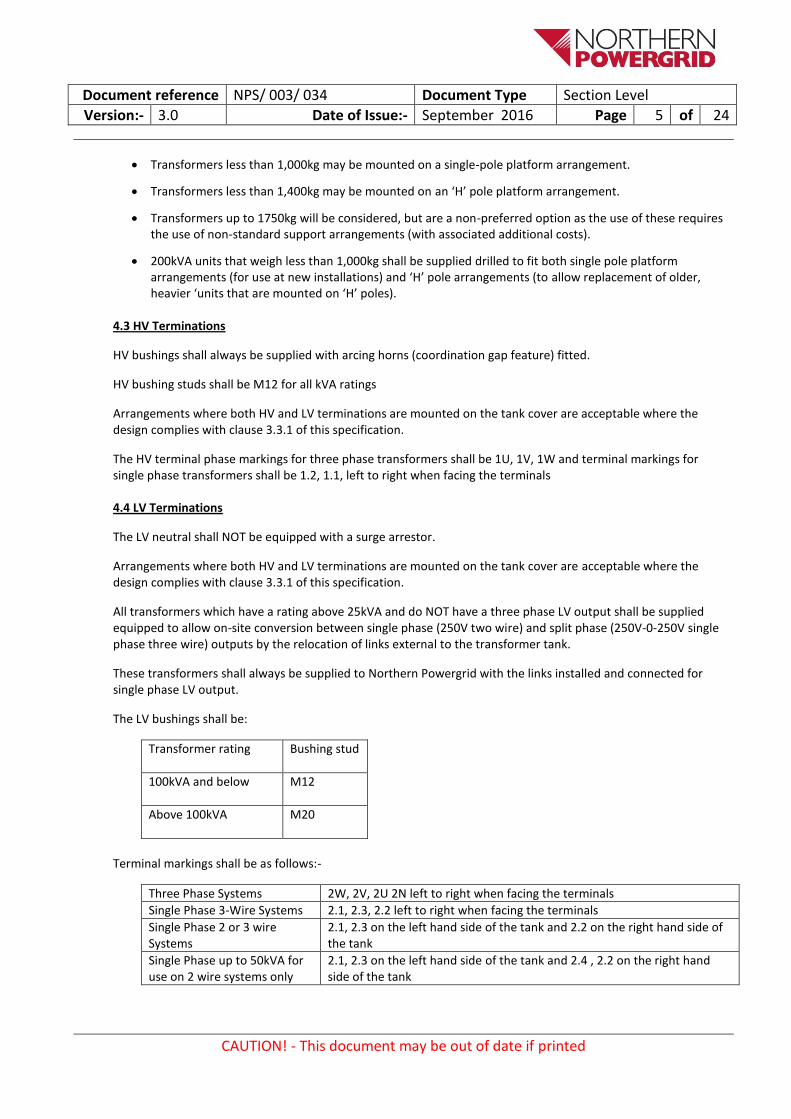
The LV bushings shall be:
Transformer rating Bushing stud
100kVA and below M12
Above 100kVA M20
Terminal markings shall be as follows:-
Three Phase Systems 2W, 2V, 2U 2N left to right when facing the terminals
Single Phase 3-Wire Systems 2.1, 2.3, 2.2 left to right when facing the terminals
Single Phase 2 or 3 wire Systems
2.1, 2.3 on the left hand side of the tank and 2.2 on the right hand side of the tank
Single Phase up to 50kVA for use on 2 wire systems only
2.1, 2.3 on the left hand side of the tank and 2.4 , 2.2 on the right hand side of the tank
Document reference NPS/ 003/ 034 Document Type Section Level
Version:- 3.0 Date of Issue:- September 2016 Page 6 of 24
CAUTION! - This document may be out of date if printed
4.6 Specification of Tappings
4.6.1 General
All transformers shall be provided with a de-energised tap-changer operated by an external self-positioning tapping switch in accordance with IEC 60214-1 Clause 7. Tappings shall be provided on the higher voltage winding for a variation of the no-load primary voltage of -2.5%, 0%, +2.5%, +5% and +7.5%.
With respect to the tappings, switch position No1 shall correspond to the +7.5% tapping position. Unless specified otherwise all transformers shall be supplied with the tap changer set at tap position 3 i.e. +2.5%.
4.6.2 Single-Phase 16 kVA, 25 kVA and 50 kVA transformer tappings
On single-phase pole mounted transformers rated 16kVA, 25kVA and 50kVA, with standard voltage ratios of 6,600/250V, 11,000/250, 20,000/250 and 33,000/250V, the Northern Powergrid preference is still for an external self-positioning tapping switch, however an alternative tapping arrangement may be provided on the lower voltage winding, by means of connection to external LV bushings.
5.1 Dielectric Test Levels
Insulation levels for Pole Mounted Transformers shall be in accordance with Table 3, the test voltages for particularly exposed conditions shall apply.
Special Requirements 3.3
3.3.1 HV & LV Bushing Arrangements
In addition to the HV and LV arrangements detailed in clause 4.3 and 4.4 of ENA TS 35-1 Part 4; arrangements where both HV and LV terminations are mounted on the tank cover are acceptable.
Where both HV and LV terminations are mounted on the tank cover then the design shall inherently prevent voltage transfer from HV to LV, taking account of possible causes including: snow, vandalism, debris, birds or animals. If this cannot be achieved practicably then the LV terminals shall be equipped with approved, individual, durable, long term UV stable, HV rated, insulating shrouds that do not compromise the performance of the LV bushings, but do provide protection against HV to LV voltage transfer.
Where both terminations are mounted on the tank cover then the design shall take particular account of insulation compromise as result of snowfall and the resulting accumulation of snow on and around the bushings and tank cover.
The bushing arrangements and associated features shall not compromise any performance criteria of the unit and shall not compromise the physical performance, or the ergonomic considerations, of the HV and LV connections. The ‘as installed’ design of bushings and associated parts shall be the arrangement used when subjecting the transformers to type tests and special tests.
3.3.2 G78 Transformers
Northern Powergrid requires a small number of transformers that will be used to provide Low Voltage supplies to mobile phone base stations with antennae on High Voltage structures and these transformers shall comply with the requirements of Energy Networks Association Engineering Recommendation G78-2.
Document reference NPS/ 003/ 034 Document Type Section Level
Version:- 3.0 Date of Issue:- September 2016 Page 7 of 24
CAUTION! - This document may be out of date if printed
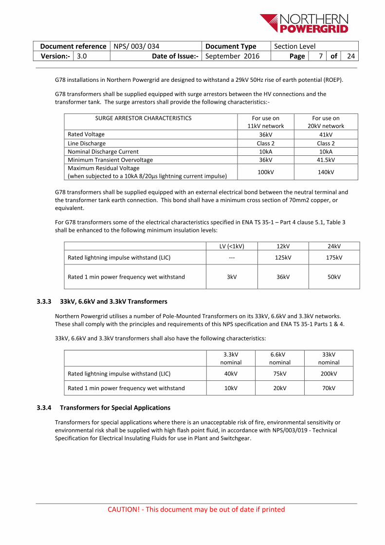
G78 installations in Northern Powergrid are designed to withstand a 29kV 50Hz rise of earth potential (ROEP).
G78 transformers shall be supplied equipped with surge arrestors between the HV connections and the transformer tank. The surge arrestors shall provide the following characteristics:-
SURGE ARRESTOR CHARACTERISTICS For use on 11kV network
For use on 20kV network
Rated Voltage 36kV 41kV
Line Discharge Class 2 Class 2
Nominal Discharge Current 10kA 10kA
Minimum Transient Overvoltage 36kV 41.5kV
Maximum Residual Voltage (when subjected to a 10kA 8/20µs lightning current impulse)
100kV 140kV
G78 transformers shall be supplied equipped with an external electrical bond between the neutral terminal and the transformer tank earth connection. This bond shall have a minimum cross section of 70mm2 copper, or equivalent.
For G78 transformers some of the electrical characteristics specified in ENA TS 35-1 – Part 4 clause 5.1, Table 3 shall be enhanced to the following minimum insulation levels:
Rated 1 min power frequency wet withstand 3kV 36kV 50kV
3.3.3 33kV, 6.6kV and 3.3kV Transformers
Northern Powergrid utilises a number of Pole-Mounted Transformers on its 33kV, 6.6kV and 3.3kV networks. These shall comply with the principles and requirements of this NPS specification and ENA TS 35-1 Parts 1 & 4.
33kV, 6.6kV and 3.3kV transformers shall also have the following characteristics:
Rated 1 min power frequency wet withstand 10kV 20kV 70kV
3.3.4 Transformers for Special Applications
Transformers for special applications where there is an unacceptable risk of fire, environmental sensitivity or environmental risk shall be supplied with high flash point fluid, in accordance with NPS/003/019 - Technical Specification for Electrical Insulating Fluids for use in Plant and Switchgear.
Document reference NPS/ 003/ 034 Document Type Section Level
Version:- 3.0 Date of Issue:- September 2016 Page 8 of 24
CAUTION! - This document may be out of date if printed
4. References
External Documentation 4.1
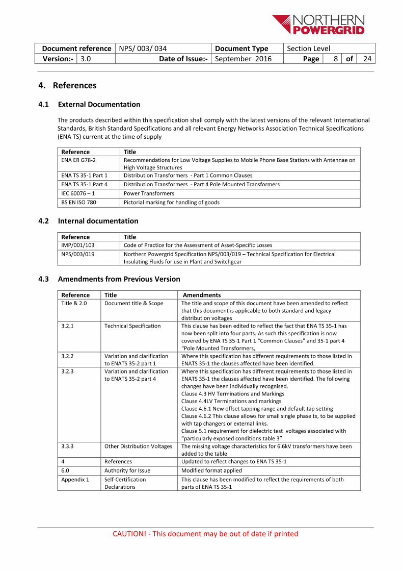
The products described within this specification shall comply with the latest versions of the relevant International Standards, British Standard Specifications and all relevant Energy Networks Association Technical Specifications (ENA TS) current at the time of supply
Reference Title ENA ER G78-2 Recommendations for Low Voltage Supplies to Mobile Phone Base Stations with Antennae on
High Voltage Structures
ENA TS 35-1 Part 1 Distribution Transformers - Part 1 Common Clauses
ENA TS 35-1 Part 4 Distribution Transformers - Part 4 Pole Mounted Transformers
IEC 60076 – 1 Power Transformers
BS EN ISO 780 Pictorial marking for handling of goods
Internal documentation 4.2
Reference Title IMP/001/103 Code of Practice for the Assessment of Asset-Specific Losses
NPS/003/019 Northern Powergrid Specification NPS/003/019 – Technical Specification for Electrical Insulating Fluids for use in Plant and Switchgear
Amendments from Previous Version 4.3
Reference Title Amendments Title & 2.0 Document title & Scope The title and scope of this document have been amended to reflect
that this document is applicable to both standard and legacy distribution voltages
3.2.1 Technical Specification This clause has been edited to reflect the fact that ENA TS 35-1 has now been split into four parts. As such this specification is now covered by ENA TS 35-1 Part 1 “Common Clauses” and 35-1 part 4 “Pole Mounted Transformers,
3.2.2 Variation and clarification to ENATS 35-2 part 1
Where this specification has different requirements to those listed in ENATS 35-1 the clauses affected have been identified.
3.2.3 Variation and clarification to ENATS 35-2 part 4
Where this specification has different requirements to those listed in ENATS 35-1 the clauses affected have been identified. The following changes have been individually recognised. Clause 4.3 HV Terminations and Markings Clause 4.4LV Terminations and markings Clause 4.6.1 New offset tapping range and default tap setting Clause 4.6.2 This clause allows for small single phase tx, to be supplied with tap changers or external links. Clause 5.1 requirement for dielectric test voltages associated with “particularly exposed conditions table 3”
3.3.3 Other Distribution Voltages The missing voltage characteristics for 6.6kV transformers have been added to the table
4 References Updated to reflect changes to ENA TS 35-1
6.0 Authority for Issue Modified format applied
Appendix 1 Self-Certification Declarations
This clause has been modified to reflect the requirements of both parts of ENA TS 35-1
Document reference NPS/ 003/ 034 Document Type Section Level
Version:- 3.0 Date of Issue:- September 2016 Page 9 of 24
CAUTION! - This document may be out of date if printed
5. Definitions
Reference Title None n/a
Document reference NPS/ 003/ 034 Document Type Section Level
Version:- 3.0 Date of Issue:- September 2016 Page 10 of 24
CAUTION! - This document may be out of date if printed
6. Authority for issue
CDS Assurance 6.1I sign to confirm that I have completed and checked this document and I am satisfied with its content and submit it for approval and authorisation.
Sign Date
Dan Rodrigues CDS Administrator Dan Rodrigues 19/09/2016
Author 6.2I sign to confirm that I have completed and checked this document and I am satisfied with its content and submit it for approval and authorisation.
Review Period - This document should be reviewed within the following time period.
Standard CDS review of 3 years Non Standard Review Period & Reason
No Period: 5 Reason: Update will be dictated by contact renewal date or any significant changes in the specification or documents referenced
Should this document be displayed on the Northern Powergrid external website? Yes
I sign to confirm that I am satisfied with all aspects of the content and preparation of this document and submit it for approval and authorisation.
Sign Date
David Blackledge Senior Policy & Standards Engineer David Blackledge 19/09/2016
Authorisation 6.4
Authorisation is granted for publication of this document.
Sign Date
Mark Nicholson Head Of System Strategy Mark Nicholson 21/09/2016
Document reference NPS/ 003/ 034 Document Type Code of Practice
Version:- 3.0 Date of Issue:- September 2016 Page 11 of 24
CAUTION! - This document may be out of date if printed
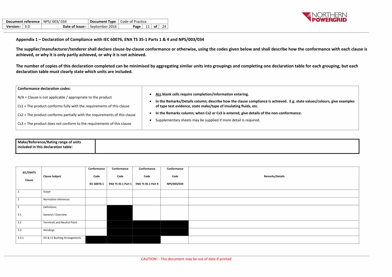
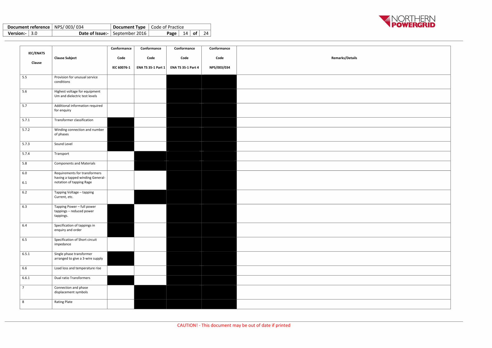
Appendix 1 – Declaration of Compliance with IEC 60076, ENA TS 35-1 Parts 1 & 4 and NPS/003/034
The supplier/manufacturer/tenderer shall declare clause-by-clause conformance or otherwise, using the codes given below and shall describe how the conformance with each clause is achieved, or why it is only partly achieved, or why it is not achieved. The number of copies of this declaration completed can be minimised by aggregating similar units into groupings and completing one declaration table for each grouping, but each declaration table must clearly state which units are included.
Conformance declaration codes:
N/A = Clause is not applicable / appropriate to the product
Cs1 = The product conforms fully with the requirements of this clause
Cs2 = The product conforms partially with the requirements of this clause
Cs3 = The product does not conform to the requirements of this clause
ALL blank cells require completion/information entering.
In the Remarks/Details column; describe how the clause compliance is achieved. E.g. state values/colours, give examples of type test evidence, state make/type of insulating fluids, etc.
In the Remarks column; when Cs2 or Cs3 is entered, give details of the non-conformance.
Supplementary sheets may be supplied if more detail is required.
Make/Reference/Rating range of units included in this declaration table:
IEC/ENATS
Clause
Clause Subject
Conformance
Code
IEC 60076-1
Conformance
Code
ENA TS 35-1 Part 1
Conformance
Code
ENA TS 35-1 Part 4
Conformance
Code
NPS/003/034
Remarks/Details
1 Scope
2 Normative references
3
3.1
Definitions
General / Overview
3.2 Terminals and Neutral Point
3.3 Windings
3.3.1 HV & LV Bushing Arrangements
Document reference NPS/ 003/ 034 Document Type Code of Practice
Version:- 3.0 Date of Issue:- September 2016 Page 12 of 24
CAUTION! - This document may be out of date if printed
IEC/ENATS
Clause
Clause Subject
Conformance
Code
IEC 60076-1
Conformance
Code
ENA TS 35-1 Part 1
Conformance
Code
ENA TS 35-1 Part 4
Conformance
Code
NPS/003/034
Remarks/Details
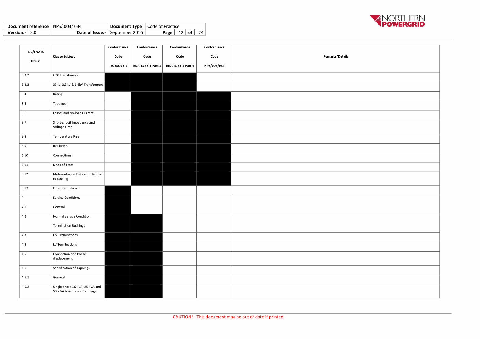
3.3.2 G78 Transformers
3.3.3 33kV, 3.3kV & 6.6kV Transformers
3.4 Rating
3.5 Tappings
3.6 Losses and No-load Current
3.7 Short-circuit Impedance and Voltage Drop
3.8 Temperature Rise
3.9 Insulation
3.10 Connections
3.11 Kinds of Tests
3.12 Meteorological Data with Respect to Cooling
3.13 Other Definitions
4
4.1
Service Conditions
General
4.2 Normal Service Condition
Termination Bushings
4.3 HV Terminations
4.4 LV Terminations
4.5 Connection and Phase displacement
4.6 Specification of Tappings
4.6.1 General
4.6.2 Single phase 16 kVA, 25 kVA and 50 k VA transformer tappings
Document reference NPS/ 003/ 034 Document Type Code of Practice
Version:- 3.0 Date of Issue:- September 2016 Page 13 of 24
CAUTION! - This document may be out of date if printed
IEC/ENATS
Clause
Clause Subject
Conformance
Code
IEC 60076-1
Conformance
Code
ENA TS 35-1 Part 1
Conformance
Code
ENA TS 35-1 Part 4
Conformance
Code
NPS/003/034
Remarks/Details
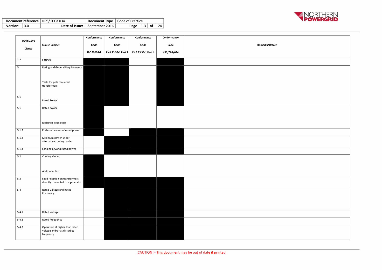
4.7 Fittings
5
5.1
Rating and General Requirements
Tests for pole mounted transformers
Rated Power
5.1 Rated power
Dielectric Test levels
5.1.2 Preferred values of rated power
5.1.3 Minimum power under alternative cooling modes
5.1.4 Loading beyond rated power
5.2 Cooling Mode
Additional test
5.3 Load rejection on transformers directly connected to a generator
5.4
Rated Voltage and Rated Frequency
5.4.1 Rated Voltage
5.4.2 Rated Frequency
5.4.3 Operation at higher than rated voltage and/or at disturbed frequency
Document reference NPS/ 003/ 034 Document Type Code of Practice
Version:- 3.0 Date of Issue:- September 2016 Page 14 of 24
CAUTION! - This document may be out of date if printed
IEC/ENATS
Clause
Clause Subject
Conformance
Code
IEC 60076-1
Conformance
Code
ENA TS 35-1 Part 1
Conformance
Code
ENA TS 35-1 Part 4
Conformance
Code
NPS/003/034
Remarks/Details
5.5 Provision for unusual service conditions
5.6 Highest voltage for equipment Um and dielectric test levels
5.7 Additional information required for enquiry
5.7.1 Transformer classification
5.7.2 Winding connection and number of phases
5.7.3 Sound Level
5.7.4 Transport
5.8 Components and Materials
6.0
6.1
Requirements for transformers having a tapped winding General- notation of tapping Rage
6.2 Tapping Voltage – tapping Current, etc.
6.3 Tapping Power – full power tappings – reduced power tappings.
6.4 Specification of tappings in enquiry and order
6.5 Specification of Short circuit impedance
6.5.1 Single phase transformer arranged to give a 3-wire supply
6.6 Load loss and temperature rise
6.6.1 Dual ratio Transformers
7 Connection and phase displacement symbols
8 Rating Plate
Document reference NPS/ 003/ 034 Document Type Code of Practice
Version:- 3.0 Date of Issue:- September 2016 Page 15 of 24
CAUTION! - This document may be out of date if printed
IEC/ENATS
Clause
Clause Subject
Conformance
Code
IEC 60076-1
Conformance
Code
ENA TS 35-1 Part 1
Conformance
Code
ENA TS 35-1 Part 4
Conformance
Code
NPS/003/034
Remarks/Details
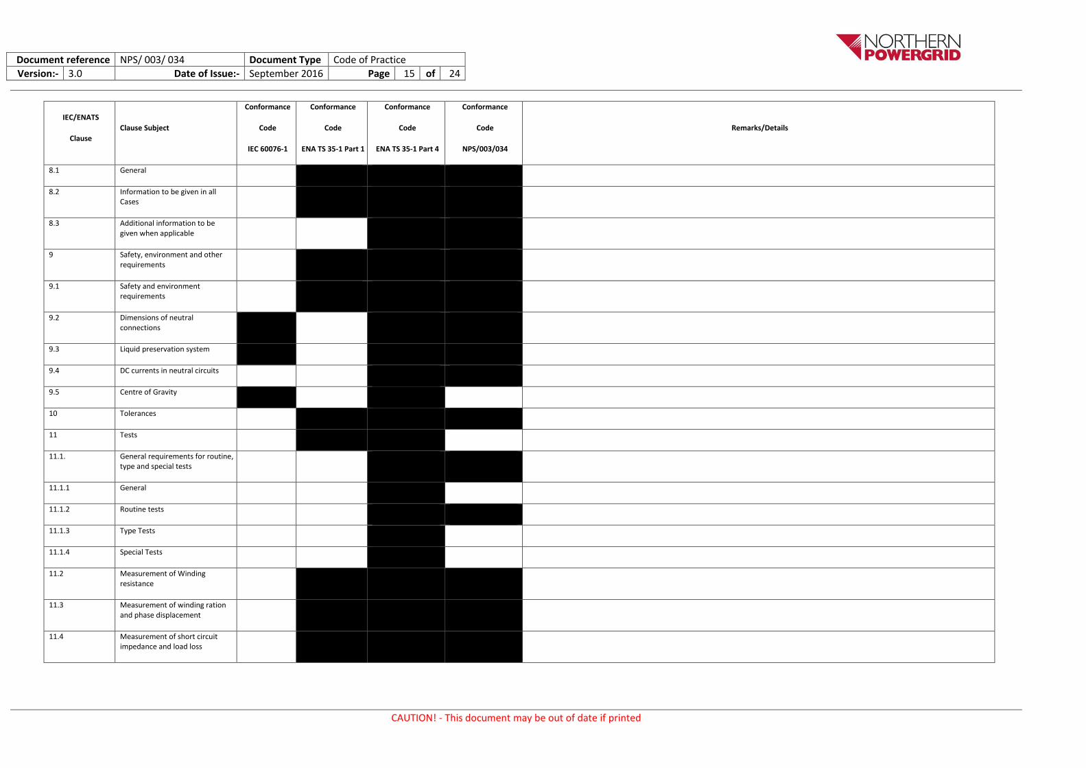
8.1 General
8.2 Information to be given in all Cases
8.3 Additional information to be given when applicable
9 Safety, environment and other requirements
9.1 Safety and environment requirements
9.2 Dimensions of neutral connections
9.3 Liquid preservation system
9.4 DC currents in neutral circuits
9.5 Centre of Gravity
10 Tolerances
11 Tests
11.1. General requirements for routine, type and special tests
11.1.1 General
11.1.2 Routine tests
11.1.3 Type Tests
11.1.4 Special Tests
11.2 Measurement of Winding resistance
11.3 Measurement of winding ration and phase displacement
11.4 Measurement of short circuit impedance and load loss
Document reference NPS/ 003/ 034 Document Type Code of Practice
Version:- 3.0 Date of Issue:- September 2016 Page 16 of 24
CAUTION! - This document may be out of date if printed
IEC/ENATS
Clause
Clause Subject
Conformance
Code
IEC 60076-1
Conformance
Code
ENA TS 35-1 Part 1
Conformance
Code
ENA TS 35-1 Part 4
Conformance
Code
NPS/003/034
Remarks/Details
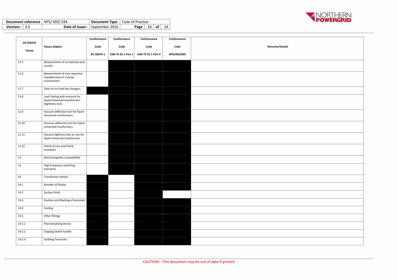
11.5 Measurement of no load loss and current
11.6 Measurement of zero sequence impedance(s) on 3 phase transformers
11.7 Tests on on-load tap changers
11.8 Leak Testing with pressure for liquid immersed transformers (tightness test)
11.9 Vacuum deflection test for liquid immersed transformers.
11.10 Pressure deflection test for liquid immersed transformers.
11.11 Vacuum tightness test on site for liquid immersed transformers
11.12 Check of core and frame insulation
12 Electromagnetic compatibility
13 High Frequency switching transients
14 Transformer details
14.1 Number of Phases
14.2 Surface finish
14.3 Position and Marking of terminals
14.4 Cooling
14.5 Other fittings
14.5.1 Plain breathing device
14.5.2 Tapping Switch handle
14.5.3 Earthing Terminals
Document reference NPS/ 003/ 034 Document Type Code of Practice
Version:- 3.0 Date of Issue:- September 2016 Page 17 of 24
CAUTION! - This document may be out of date if printed
IEC/ENATS
Clause
Clause Subject
Conformance
Code
IEC 60076-1
Conformance
Code
ENA TS 35-1 Part 1
Conformance
Code
ENA TS 35-1 Part 4
Conformance
Code
NPS/003/034
Remarks/Details
14.5.4 Lifting Fittings
15 Documentation
15.1 Drawings
15.2 Assembly, operations and maintenance instructions
15.3 Test Data
Document reference NPS/ 003/ 034 Document Type Code of Practice
Version:- 3.0 Date of Issue:- September 2016 Page 18 of 24
CAUTION! - This document may be out of date if printed
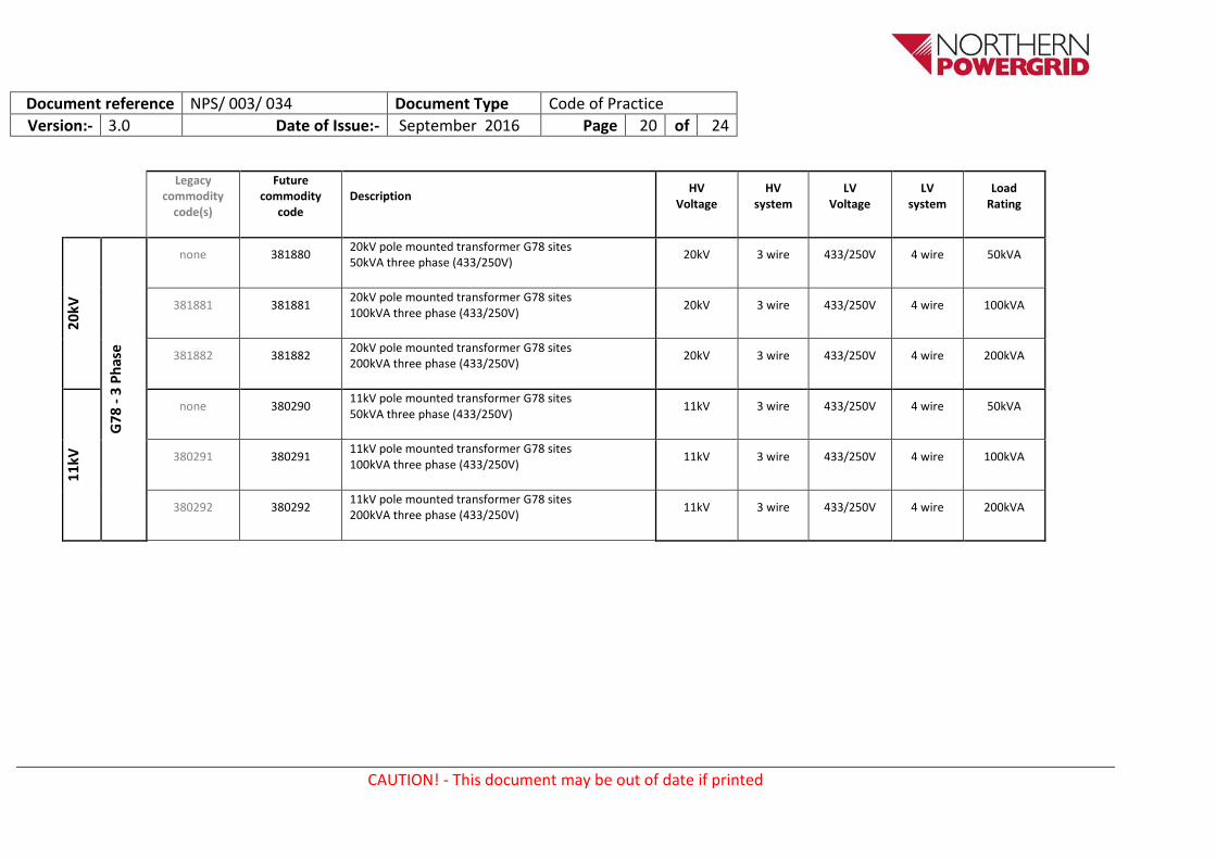
Appendix 2 – Schedule of Requirements
Legacy commodity
code(s)
Future commodity
code Description
HV Voltage
HV system
LV Voltage
LV system
Load Rating
20
kV
1 P
has
e
382056 382056 20kV pole mounted transformer 25kVA single phase (250V) 2 wire HV and 2 wire LV
20kV 2 wire 250V 2 wire 25kVA
Co
mb
ined
1 P
has
e
or
Split
Ph
ase
382060 382060
20kV pole mounted Tx 50kVA 1ph (250V) 2 wire HV & 2 wire LV, OR 25kVA per phase Split Phase 2 wire HV & 3 wire LV (250-0-250V) LV links, external to the tank, configurable on site
20kV 2 wire 250V
or 250-0-250V
2 wire or
3 wire
50kVA or
25kVA/ph
382075 382075
20kV pole mounted Tx 100kVA 1ph (250V) 2 wire HV & 2 wire LV, OR 50kVA per phase Split Phase 2 wire HV & 3 wire LV (250-0-250V) LV links, external to the tank, configurable on site
20kV 2 wire 250 or
250-0-250V
2 wire or
3 wire
100kVA or
50kVA/ph
none 382076
20kV pole mount Tx 200kVA 1ph (250V) 2 wire HV & 2 wire LV, OR 100kVA per phase Split Phase 2 wire HV & 3 wire LV (250-0-250V) LV links, external to the tank, configurable on site
20kV 2 wire 250 or
250-0-250V
2 wire or
3 wire
200kVA or
100kVA/ph
3 P
has
e
381689 381689 20kV pole mounted transformer 50kVA three phase (433/250V)
20kV 3 wire 433/250V 4 wire 50kVA
381693 381693 20kV pole mounted transformer 100kVA three phase (433/250V)
20kV 3 wire 433/250V 4 wire 100kVA
381725 381725 20kV pole mounted transformer 200kVA three phase (433/250V)
20kV 3 wire 433/250V 4 wire 200kVA
none 381726 20kV pole mounted transformer 315kVA three phase (433/250V)
20kV 3 wire 433/250V 4 wire 315kVA
Document reference NPS/ 003/ 034 Document Type Code of Practice
Version:- 3.0 Date of Issue:- September 2016 Page 19 of 24
CAUTION! - This document may be out of date if printed
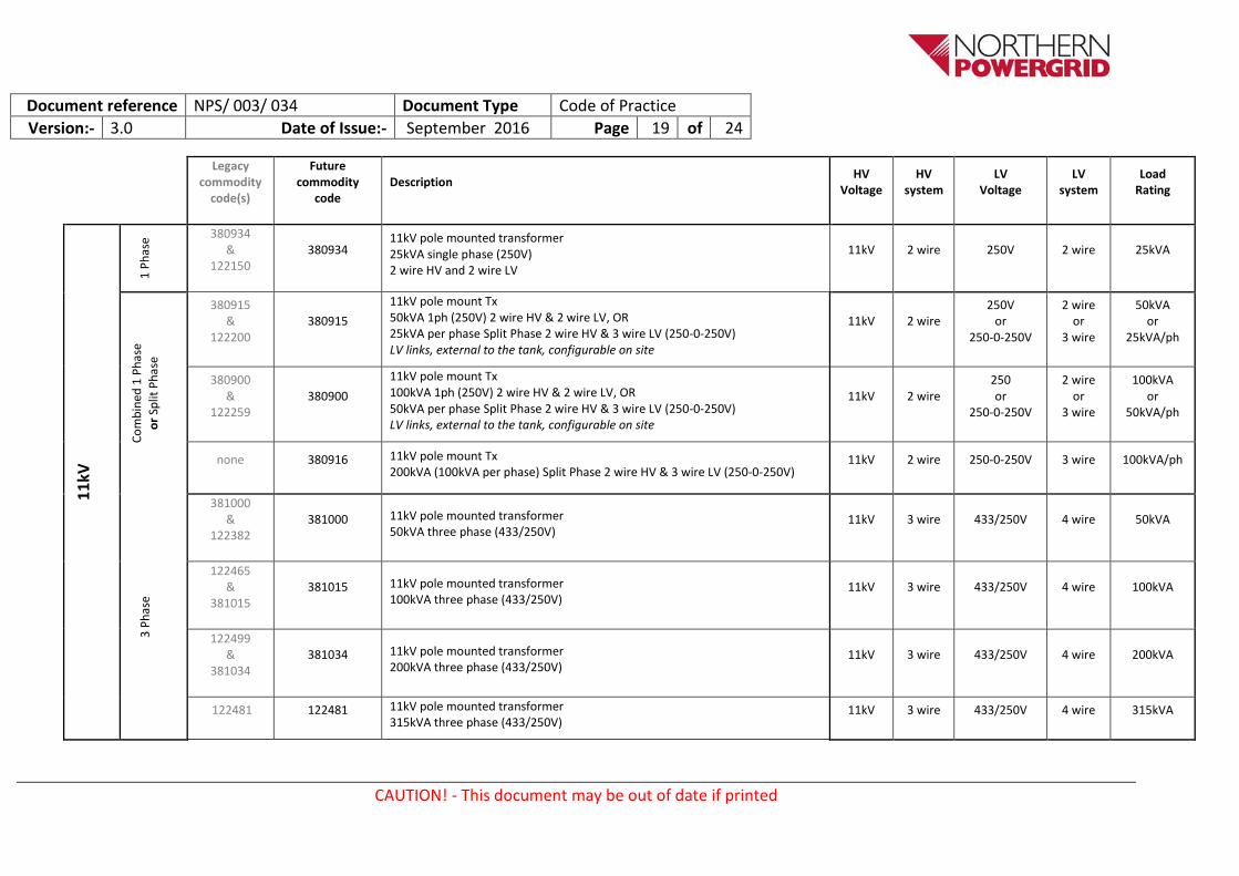
Legacy
commodity code(s)
Future commodity
code Description
HV Voltage
HV system
LV Voltage
LV system
Load Rating
11
kV
1 P
has
e 380934
& 122150
380934 11kV pole mounted transformer 25kVA single phase (250V) 2 wire HV and 2 wire LV
11kV 2 wire 250V 2 wire 25kVA
Co
mb
ined
1 P
has
e
or
Split
Ph
ase
380915 &
122200 380915
11kV pole mount Tx 50kVA 1ph (250V) 2 wire HV & 2 wire LV, OR 25kVA per phase Split Phase 2 wire HV & 3 wire LV (250-0-250V) LV links, external to the tank, configurable on site
11kV 2 wire 250V
or 250-0-250V
2 wire or
3 wire
50kVA or
25kVA/ph
380900 &
122259 380900
11kV pole mount Tx 100kVA 1ph (250V) 2 wire HV & 2 wire LV, OR 50kVA per phase Split Phase 2 wire HV & 3 wire LV (250-0-250V) LV links, external to the tank, configurable on site
11kV 2 wire 250 or
250-0-250V
2 wire or
3 wire
100kVA or
50kVA/ph
none 380916 11kV pole mount Tx 200kVA (100kVA per phase) Split Phase 2 wire HV & 3 wire LV (250-0-250V)
Document reference NPS/ 003 / 034 Document Type Code of Practice
Version:- 3.0 Date of Issue:- September 2016 Page 21 of 24
CAUTION! - This document may be out of date if printed
Appendix 3 – Addendum to Suppliers Requirements Losses
Lifetime costs shall be calculated, for every design variant, using the formula below and the latest Northern Powergrid capitalisation figures. The Northern Powergrid loss £/kW figures incorporate utilisation factor and time span. The maximum £/kW losses are detailed in IMP/001/103, clause 3.3.3 and Appendix 5
Lifetime Cost = Purchase price + (No load loss kW x No load £/kW) + (Load loss kW x Load loss £/kW)
The tenderer shall supply details of each element of this calculation, in addition to the answer. The tenderer shall declare the maximum guaranteed loss figures for each design variant.
Appendix 4 – Pre-commission testing, Routine Inspection and Maintenance Requirements Suppliers shall provide details of the recommended pre-commission testing and inspection required. They shall also provide information regarding periodic inspection and maintenance requirements to be undertaken during the lifetime of their product.
Detailed inspection and maintenance instructions shall be also be provided.
Document reference NPS/ 003 / 034 Document Type Code of Practice
Version:- 3.0 Date of Issue:- September 2016 Page 22 of 24
CAUTION! - This document may be out of date if printed
Appendix 5 – Summary of Test Requirements
IEC 60076-1
IEC 60076-3
ENATS 35-1 Northern Powergrid
NPS
Northern Powergrid
TEST REQUIREMENT
IEC 60076 - 10.1.1 Routine tests
10.1.1.a Measurement of winding resistance (10.2)
Routine Routine
10.1.1.b Measurement of voltage ratio and check of phase displacement (10.3)
Routine Routine
10.1.1.c Measurement of short-circuit impedance and load loss (10.4)
Routine Routine
10.1.1.d Measurement of no-load loss and current (10.5)
Table 1 Switching Impulse (SI) - Not Applicable (clause 15)
Not Applicable
Table 1 Long Duration AC (ACLD) - Not Applicable (clause 12.4)
Not Applicable
Table 1 Short Duration AC (ACSD) (clauses 12.2
Routine Routine
Table 1 Separate source AC (clause 11)
Routine Routine
7.3 Tests to be done in sequence as set out in 60076-3
---
12.2 Transformers Um<72.5kV - partial discharge measurement not required
Not Required
13.3.2 Impulse test on a neutral terminal - ENATS 35-1 Clause 19 = Special test
Special Type test Type test
10.1.1.f Tests on on-load tap-changers, where appropriate (10.8)
Not Required
IEC 60076 - 10.1.2 Type tests
10.1.2.a Temperature-rise test (60076-2)
Type test Type test
10.1.2.b Dielectric type tests (60076-3) - see 10.1.1 above
---
Document reference NPS/ 003 / 034 Document Type Code of Practice
Version:- 3.0 Date of Issue:- September 2016 Page 23 of 24
CAUTION! - This document may be out of date if printed
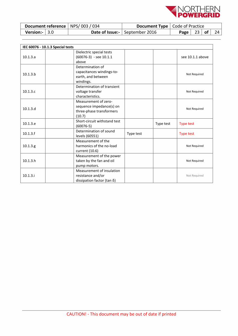
IEC 60076 - 10.1.3 Special tests
10.1.3.a Dielectric special tests (60076-3) - see 10.1.1 above
see 10.1.1 above
10.1.3.b
Determination of capacitances windings-to-earth, and between windings.
Not Required
10.1.3.c Determination of transient voltage transfer characteristics.
Not Required
10.1.3.d
Measurement of zero-sequence impedance(s) on three-phase transformers (10.7)
Not Required
10.1.3.e Short-circuit withstand test (60076-5)
Type test Type test
10.1.3.f Determination of sound levels (60551)
Type test Type test
10.1.3.g Measurement of the harmonics of the no-load current (10.6)
Not Required
10.1.3.h Measurement of the power taken by the fan and oil pump motors.
Not Required
10.1.3.i Measurement of insulation resistance and/or dissipation factor (tan δ)
Not Required
Document reference NPS/ 003 / 034 Document Type Code of Practice
Version:- 3.0 Date of Issue:- September 2016 Page 24 of 24
CAUTION! - This document may be out of date if printed
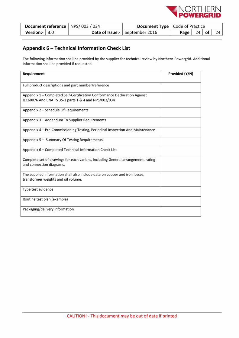
Appendix 6 – Technical Information Check List
The following information shall be provided by the supplier for technical review by Northern Powergrid. Additional information shall be provided if requested.
Requirement Provided (Y/N)
Full product descriptions and part number/reference
Appendix 1 – Completed Self-Certification Conformance Declaration Against IEC60076 And ENA TS 35-1 parts 1 & 4 and NPS/003/034
Appendix 2 – Schedule Of Requirements
Appendix 3 – Addendum To Supplier Requirements
Appendix 4 – Pre-Commissioning Testing, Periodical Inspection And Maintenance
Appendix 5 – Summary Of Testing Requirements
Appendix 6 – Completed Technical Information Check List
Complete set of drawings for each variant, including General arrangement, rating and connection diagrams.
The supplied information shall also include data on copper and iron losses, transformer weights and oil volume.