259
SETUP MANUAL Programmable Terminals NS-Series NS12-TS00@-V1, NS12-TS01@-V1 NS10-TV00@-V1, NS10-TV01@-V1 NS8-TV@0@-V1, NS8-TV@1@-V1 NS5-SQ00@-V1, NS5-SQ01@-V1 Cat.No. V083-E1-03

SETUP MANUAL
Programmable Terminals
NS-SeriesNS12-TS00@@-V1, NS12-TS01@@-V1NS10-TV00@@-V1, NS10-TV01@@-V1NS8-TV@@0@@-V1, NS8-TV@@1@@-V1NS5-SQ00@@-V1, NS5-SQ01@@-V1
Cat.No. V083-E1-03
1
NoticeOMRON products are manufactured for use according to proper procedures by aqualified operator and only for the purposes described in this manual.
The following conventions are used to indicate and classify precautions in this manual.Always heed the information provided with them. Failure to heed precautions canresult in injury to people or damage to property.
! DANGER Indicates an imminently hazardous situation which, if not avoided, will result in death orserious injury.
! WARNING Indicates a potentially hazardous situation which, if not avoided, could result in death orserious injury.
! Caution Indicates a potentially hazardous situation which, if not avoided, may result in minor ormoderate injury, or property damage.
OMRON Product ReferencesAll OMRON products are capitalized in this manual. The word "Unit" is also capitalized when itrefers to an OMRON product, regardless of whether or not it appears in the proper name ofthe product.
The abbreviation "Ch," which appears in some displays and on some OMRON products,often means "word" and is abbreviated "Wd" in documentation in this sense.
The abbreviation "PLC" means Programmable Controller.
The abbreviation “host” means a controller, such as an IBM PC/AT or compatible computer,that controls a PT (Programmable Terminal).
Visual AidsThe following headings appear in the left column of the manual to help you locate differenttypes of information.
Note Indicates information of particular interest for efficient and convenient operationof the product.
Reference Indicates supplementary information on related topics that may be of interest tothe user.
1, 2, 3... 1. Indicates lists of one sort or another, such as procedures, checklists, etc.
CS1G-CPU@@ -VI Boxes in model numbers indicate variable characters. For example, "CS1G-CPU@@ -EV1" indicates the following models: CS1G-CPU42-EV1, CS1G-CPU43-EV1, CS1G-CPU44-EV1, and CS1G-CPU45-EV1.
OMRON, 2004All rights reserved. No part of this publication may be reproduced, stored in a retrieval system, or transmitted, in any form, orby any means, mechanical, electronic, photocopying, recording, or otherwise, without the prior written permission ofOMRON.
No patent liability is assumed with respect to the use of the information contained herein. Moreover, because OMRON isconstantly striving to improve its high-quality products, the information contained in this manual is subject to change withoutnotice. Every precaution has been taken in the preparation of this manual. Nevertheless, OMRON assumes no responsibilityfor errors or omissions. Neither is any liability assumed for damages resulting from the use of the information contained inthis publication.

2
ContentsNotice ..............................................................................................................................................1About this Manual ...............................................................................................................................6Related Manuals ..................................................................................................................................7Terminology ........................................................................................................................................8Introduction .........................................................................................................................................9
Section 1 Overview1-1 NS-series PT Functions and Operation............................................................................................ 1-2
1-1-1 PT Functions for FA Manufacturing Sites ........................................................................... 1-21-1-2 NS-series PT Operating System........................................................................................... 1-3
1-2 Communications with the Host ....................................................................................................... 1-51-2-1 What is an NT Link?............................................................................................................ 1-61-2-2 Ethernet ................................................................................................................................ 1-61-2-3 Controller Link..................................................................................................................... 1-61-2-4 Host Link ............................................................................................................................. 1-6
1-3 System Configuration ...................................................................................................................... 1-71-3-1 Supported Peripheral Devices .............................................................................................. 1-7
1-4 Procedure for Running NS-series PTs............................................................................................. 1-9
Section 2 Before Connecting2-1 Connecting the Host ........................................................................................................................ 2-2
2-1-1 Communications Types and Connection Methods............................................................... 2-22-2 Part Names and Functions ............................................................................................................... 2-7
Section 3 Installing the PT and Connecting Peripheral Devices3-1 Installing the PT .............................................................................................................................. 3-3
3-1-1 Installation Environment...................................................................................................... 3-33-1-2 Installing RS-232C/RS-422A Converters ............................................................................ 3-43-1-3 Mounting the PT to the Control Panel ................................................................................. 3-43-1-4 Connecting the Power Supply.............................................................................................. 3-53-1-5 Wiring the Ground Wire ...................................................................................................... 3-73-1-6 Peripheral Device Connection Limitations .......................................................................... 3-7
3-2 Starting the PT................................................................................................................................. 3-83-2-1 Operation at Startup ............................................................................................................. 3-83-2-2 Starting the PT for the First Time ...................................................................................... 3-10
3-3 Connecting the NS-Designer ......................................................................................................... 3-123-4 Connecting to Bar Code Readers................................................................................................... 3-13
3-4-1 Connection Methods .......................................................................................................... 3-133-4-2 Setting Bar Code Readers .................................................................................................. 3-143-4-3 Data Format ....................................................................................................................... 3-153-4-4 Bar Code Input ................................................................................................................... 3-15
3-5 Connecting to Printers ................................................................................................................... 3-163-5-1 Connection Method............................................................................................................ 3-16
3-6 Using Memory Cards..................................................................................................................... 3-17
3
3-6-1 Installation.......................................................................................................................... 3-183-6-2 Replacing System Programs .............................................................................................. 3-193-6-3 Transferring Data with Memory Cards .............................................................................. 3-19
3-7 Installing the Video Input Unit ...................................................................................................... 3-263-7-1 Video Input Unit Components ........................................................................................... 3-263-7-2 Nomenclature and Functions.............................................................................................. 3-273-7-3 Installation Method for Video Input Unit........................................................................... 3-283-7-4 Connecting to Video Input Connectors.............................................................................. 3-33
3-8 Installing the Controller Link Interface Unit ................................................................................. 3-383-8-1 Controller Link Interface Unit Components ...................................................................... 3-383-8-2 Nomenclature and Functions.............................................................................................. 3-393-8-3 Installation Method for Controller Link Interface Unit...................................................... 3-423-8-4 Wiring ................................................................................................................................ 3-49
Section 4 Connecting the Host to Serial Port4-1 1:1 Host Connection ........................................................................................................................ 4-2
4-1-1 Connection Methods ............................................................................................................ 4-24-1-2 Unit Setting Methods ........................................................................................................... 4-4
4-2 1:N Host Connection ....................................................................................................................... 4-74-2-1 Connection Methods ............................................................................................................ 4-74-2-2 Unit Setting Methods ........................................................................................................... 4-7
4-3 High-speed 1:N NT Link............................................................................................................... 4-154-3-1 Unit Setting Methods ......................................................................................................... 4-16
4-4 Recommended Connector Cables.................................................................................................. 4-23
Section 5 Connecting to Host via Ethernet or Controller Link5-1 Connecting to Host Via Ethernet..................................................................................................... 5-2
5-1-1 Host Types and Settings....................................................................................................... 5-35-2 Connecting to the Host Using Controller Link.............................................................................. 5-15
5-2-1 What Is a Controller Link Network?.................................................................................. 5-155-2-2 Data Links.......................................................................................................................... 5-165-2-3 Troubleshooting Using Indicators...................................................................................... 5-21
Section 6 System Menu Operations6-1 Operating Modes and System Menu................................................................................................ 6-3
6-1-1 Mode Configuration............................................................................................................. 6-36-1-2 System Menu Configuration ................................................................................................ 6-36-1-3 Overview of Menu Items ..................................................................................................... 6-46-1-4 Using the System Menu ....................................................................................................... 6-7
6-2 Initializing and Saving Data and Removing the Memory Card....................................................... 6-96-2-1 Screen Data Area Format ................................................................................................... 6-106-2-2 Initializing or Saving the Alarm/Event History ................................................................. 6-116-2-3 Initializing and Saving Data Log ....................................................................................... 6-126-2-4 Initializing and Saving the Operation Log ......................................................................... 6-146-2-5 Initializing and Saving the Error Log................................................................................. 6-166-2-6 Language Selection ............................................................................................................ 6-176-2-7 Removing the Memory Card.............................................................................................. 6-17
6-3 PT Settings..................................................................................................................................... 6-19

4
6-3-1 Start-up Wait Time............................................................................................................. 6-216-3-2 Screen Saver....................................................................................................................... 6-216-3-3 Key Press Sound ................................................................................................................ 6-226-3-4 Buzzer Sound ..................................................................................................................... 6-226-3-5 Backlight ............................................................................................................................ 6-236-3-6 Calendar Check.................................................................................................................. 6-236-3-7 Printer Type ....................................................................................................................... 6-246-3-8 Printing Mode .................................................................................................................... 6-256-3-9 Changing Values in Device Monitor Setting ..................................................................... 6-256-3-10 Contrast (NS5 Only) .......................................................................................................... 6-25
6-4 Project Settings .............................................................................................................................. 6-276-4-1 Project Title........................................................................................................................ 6-276-4-2 Number of Labels............................................................................................................... 6-286-4-3 Initial Screen ...................................................................................................................... 6-286-4-4 Initial Label ........................................................................................................................ 6-286-4-5 Alarm/Event History Recording Method ........................................................................... 6-286-4-6 Data Log Recording Method.............................................................................................. 6-286-4-7 Operation Log Recording Method ..................................................................................... 6-296-4-8 Error Log Recording Method............................................................................................. 6-296-4-9 System Memory ................................................................................................................. 6-29
6-5 Setting Passwords .......................................................................................................................... 6-306-6 Communications Settings .............................................................................................................. 6-31
6-6-1 Communications Conditions.............................................................................................. 6-316-6-2 Setting 1:1 NT Link ........................................................................................................... 6-336-6-3 Setting High-speed 1:N NT Links (Standard, High-speed)................................................ 6-336-6-4 Setting Ethernet.................................................................................................................. 6-346-6-5 Setting the Controller Link Network.................................................................................. 6-356-6-6 Setting Bar Code Readers .................................................................................................. 6-366-6-7 Modem Settings ................................................................................................................. 6-37
6-7 Screen Data Check......................................................................................................................... 6-386-8 Special Screens .............................................................................................................................. 6-39
6-8-1 Alarm History .................................................................................................................... 6-406-8-2 Operation Log .................................................................................................................... 6-416-8-3 Error Log............................................................................................................................ 6-426-8-4 Device Monitor .................................................................................................................. 6-436-8-5 Communication Test .......................................................................................................... 6-456-8-6 Video Configuration .......................................................................................................... 6-466-8-7 USB Device List ................................................................................................................ 6-486-8-8 Display Capture Data ......................................................................................................... 6-496-8-9 Memory Card Transfers ..................................................................................................... 6-506-8-10 External Application Startup.............................................................................................. 6-516-8-11 Version Display.................................................................................................................. 6-52
6-9 Hardware Check .............................................................................................................................. 6-536-9-1 LCD Check ........................................................................................................................ 6-536-9-2 Touch Switch Check .......................................................................................................... 6-54
6-10 Starting Operations........................................................................................................................ 6-55

5
Section 7 Maintenance and Troubleshooting7-1 Maintenance .................................................................................................................................... 7-2
7-1-1 Replacing the Battery........................................................................................................... 7-27-2 Inspection and Cleaning .................................................................................................................. 7-47-3 Troubleshooting and Maintenance .................................................................................................. 7-67-4 Requesting a Replacement PT....................................................................................................... 7-13
Appendices Appendix 1 Quick Reference ...............................................................................................................A-2Appendix 2 Specifications ...................................................................................................................A-3Appendix 3 Dimensions.....................................................................................................................A-10Appendix 4 Using NS-AL002 RS-232C/RS-422A Converters .........................................................A-16Appendix 5 Preparing Connecting Cables .........................................................................................A-23Appendix 6 Preparing Cables for Computer Connection...................................................................A-27Appendix 7 Preparing Connecting Cables for Bar Code Readers......................................................A-29Appendix 8 Standard Models.............................................................................................................A-31Appendix 9 List of Optional Products ...............................................................................................A-43Appendix 10 System Memory List ......................................................................................................A-46Appendix 11 Differences between “–V1” Models and Other Models .................................................A-49Appendix 12 NS5 System Menu..........................................................................................................A-50
6
About this Manual
Section 1 OverviewThis section provides an overview of the NS-series PTs, including functions, features, connection types, andcommunications methods.
Section 2 Before ConnectingThis section provides information on methods for connecting NS-series PTs that must be understood beforeconnecting the host and peripheral devices.
Section 3 Installing the PT and Connecting Peripheral DevicesThis section describes the methods used to install the PT and connect peripheral devices.
Section 4 Connecting Host to Serial PortThis section describes the methods for connecting the host to the serial port of the PT.
Section 5 Connecting to Host via Ethernet or Controller LinkThis section describes the methods for connecting the PT to the host using the PT’s Ethernet interface or ControllerLink.
Section 6 System Menu OperationsThis section describes the methods for operating the System Menu. It also provides details on functions that areuseful for NS-series PT applications and for system maintenance.
Section 7 Maintenance and TroubleshootingThis section describes the maintenance and inspection methods for preventing errors occurring, and troubleshootingmeasures when errors occur in the PT.
AppendicesDescribe hardware specifications and methods for preparing connections cables, and provide lists of standardproducts.
WARNING Failure to read and understand the information provided in this manual may result inpersonal injury or death, damage to the product, or product failure. Please read eachsection in its entirety and be sure you understand the information provided in the sectionand related sections before attempting any of the procedures or operations given.
7
Related Manuals
The following manuals are used for NS-series PTs. (The boxes at the end of the catalognumbers indicate the revision code.)
NS Series -V1 Setup Manual......................................................V083-E1-@
Provides information on NS Series V1 models (i.e., NS12-V1, NS10-V1, NS8-V1,andNS5-V1).
Describes how to connect the PT to the host and peripheral devices, methods to setupcommunications and operation, and procedures for maintenance.
Refer to the NS Series Programming Manual (V073-E1-@) for information on PTfunctions and specific operating procedures.
NS Series Setup Manual ............................................................V072-E1-@
Provides information on existing NS Series models (i.e., NS12, NS10, and NS7).
Describes how to connect the PT to the host and peripheral devices, methods to setupcommunications and operation, and procedures for maintenance.
Refer to the NS Series Programming Manual (V073-E1-@) for information on PTfunctions and specific operating procedures.
NS Series Programming Manual ................................................V073-E1-@
Describes the screen configurations, object functions, and host communications forthe PT.
NS-Designer Operation Manual..................................................V074-E1-@
Describes operating procedures for the NS-Designer, which is used to create thescreens displayed on the PT and transfer them to the PT. It includes screen creationand transfer procedures.
Thismanual
8
Terminology
The following terminology is used in this manual.
PT In this manual, indicates an NS-series Programmable Terminal.
NS Series Indicates products in the OMRON NS@@ Series of Programmable Terminals.
PLC Indicates a Programmable Controller in the OMRON SYSMAC CS/CJ, C, orCVM1/CV Series of Programmable Controllers.
CS/CJ Series Indicates Programmable Controllers in the OMRON SYSMAC CS/CJ Series ofProgrammable Controllers: CS1G, CS1H, CS1G-H, CS1H-H, CJ1G, CJ1M.
C Series Indicates products in the OMRON SYSMAC C Series of ProgrammableControllers: C200HS, C200HX(-Z), C200HG(-Z), C200HE(-Z), CQM1, CQM1H,CPM1A, CPM2A, CPM2C.
CVM1/CV Series Indicates products in the OMRON SYSMAC CVM1/ CV Series of ProgrammableControllers: CV500, CV1000, CV2000, CVM1
Serial Communications Unit Indicates a Serial Communications Unit for an OMRON CS/CJ-series PLC.
Serial CommunicationsBoard
Indicates a Serial Communications Board for an OMRON CS-series or CQM1HPLC.
Communications Board Indicates a Communications Board for an OMRON C200HX/HG/HE(-Z) PLC.
CPU Unit Indicates a CPU Unit in the OMRON SYSMAC CS/CJ, C, or CVM1/CV Series ofProgrammable Controllers.
NS-Designer Indicates the OMRON NS-Designer (NS-NSDC1-V@ ).
Host Indicates the PLC, IBM PC/AT or compatible computer, or personal computerfunctioning as the control device and interfaced with the NS-series PT.
Programming Manual Indicates the NS Series Programming Manual (V073-E1-@).

9
Introduction
• Intended Audience
This manual is intended for the following personnel, who must also have knowledge ofelectrical systems (an electrical engineer or the equivalent).
• Personnel in charge of introducing FA systems into production facilities.• Personnel in charge of designing FA systems.• Personnel in charge of installing and connecting FA systems.• Personnel in charge of managing FA systems and facilities.
• General Precautions
• The user must operate the product according to the performance specificationsdescribed in the operation manuals.
• Do not use the PT touch switch input functions for applications where danger to humanlife or serious property damage is possible, or for emergency switch applications.
• Before using the product under conditions which are not described in the manual orapplying the product to nuclear control systems, railroad systems, aviation systems,vehicles, combustion systems, medical equipment, amusement machines, safetyequipment, and other systems, machines and equipment that may have a seriousinfluence on lives and property if used improperly, consult your OMRONrepresentative.
• Make sure that the ratings and performance characteristics of the product are sufficientfor the systems, machines, and equipment, and be sure to provide the systems,machines, and equipment with double safety mechanisms.
• This manual provides information for connecting and setting up an NS-series PT. Besure to read this manual before attempting to use the PT and keep this manual close athand for reference during installation and operation.
• Safety Precautions
Do not attempt to take the Unit apart and do nottouch any internal parts while the power is beingsupplied. Doing either of these may result inelectrical shock.
• Operating Environment Precautions
1. Do not install the Unit in the following places:• Locations subject to direct sunlight• Locations subject to temperatures or humidity outside the range specified in the
specifications• Locations subject to condensation as the result of severe changes in temperature• Locations subject to corrosive or flammable gases• Locations subject to dust (especially iron dust) or salts

10
• Locations subject to exposure to water, oil, or chemicals• Locations subject to shock or vibration
2. Take appropriate and sufficient countermeasures when installing systems in the followinglocations:• Locations subject to static electricity or other forms of noise• Locations subject to strong electromagnetic fields• Locations subject to possible exposure to radioactivity• Locations close to power supplies
• Application Precautions
1. When unpacking the Units, check carefully for any external scratches or other damage.Also, shake the Units gently and check for any abnormal sound.
2. The mounting panel must be between 1.6 and 4.8 mm thick. Tighten the MountingBrackets evenly to a torque of between 0.5 and 0.6 N⋅m to maintain water and dustresistance. Make sure the panel is not dirty or warped and that it is strong enough to holdthe Units.
3. Do not let metal particles enter the Units when preparing the panel.4. If conformance to EC Directives (Low Voltage Directive) is required, use reinforced
insulation for the power supplies.5. Do not connect an AC power supply to the power terminals.6. Use a DC power supply with minimal fluctuation voltage.
Rated power supply voltage: 24 VDC(Allowable range: 20.4 to 27.6 VDC)Capacity: 25 W min. (NS5: 15 W min.)
7. Do not perform a dielectric voltage test.8. Use a twisted-pair cable with a cross-sectional area of at least 2 mm2 to connect to the
power terminals and always use M3.5 crimp terminals. Tighten the terminal screws to atorque of 0.8 N⋅m. Make sure the screws are properly tightened.
9. Ground the Unit correctly to prevent operational errors caused by noise.10. Do not touch the surface of the circuit board or the components mounted on it with your
bare hands. Discharge any static electricity from your body before handling the board.11. Confirm that the current capacity of the connected device is 250 mA or less before using
the 5-V power supply from pin 6 of the serial port A, B connectors. The 5-V output of thePT is 250 mA max. at 5 V ±5%.
12. Turn OFF the power supply before connecting or disconnecting cables.13. Always tighten the connector screws after connecting communications cables.14. The maximum tensile load for cables is 30 N. Do not apply loads greater than this.15. Confirm the safety of the system before turning ON or OFF the power supply or before
pressing the reset button.16. The whole system may stop depending on how the power supply is turned ON or OFF.
Turn ON or OFF the power supply according to the specified procedure.17. Start actual system application only after sufficiently checking screen data. macros, and
the operation of the program in the PC (host).18. Always reset the power supply after changing switch settings.19. After changing the settings of the DIP switch, always turn the power supply OFF and ON
or reset the PT.20. Do not perform the following operations while the Memory Card is being accessed:
• Turning OFF the power supply to the PT• Pressing the PT’s reset switch• Removing the Memory Card• Always following the specified procedure when removing the Memory Card.

11
21. Do not press the touch switch with a force greater than 30 N.22. Confirm the safety of the system before pressing touch switches.23. Do not accidentally press touch switches when the backlight is not lit or when the display
does not appear.24. Signals from the touch switches may not be input if the switches are pressed
consecutively at high speed. Confirm each input before proceeding to the next one.25. Before initializing screen data, confirm that existing data is backed up at the NS-
Designer.26. When changing the password with the system menu, do not reset or turn OFF the power
supply until writing is finished (i.e., until the Write Button returns to its original condition).It may become impossible to manipulate screens if the password is not set correctly.
27. When using the device monitor, confirm the safety of the system before performing thefollowing operations.• Changing monitor data• Changing operation modes• Forced setting or resetting• Changing present values or set values
28. Do not use benzene, paint thinner, or other volatile solvents, and do not use chemicallytreated cloths.
29. Dispose of any battery that has been dropped on the floor or otherwise subjected toexcessive shock.
30. Do not attempt to disassemble, repair, or modify the Unit in any way.31. Dispose of the Units and batteries according to local ordinances as they apply.32. To ensure system safety, incorporate a program that periodically calls PT operation bits
from the host side to check that the PT is properly operating.33. Do not connect an USB connector to any device that is not applicable.34. Before connecting an USB connector to a device, make sure that the device is free of
damage.35. When mounting the Battery, be sure to use the correct Battery and mount it correctly.

Section 1
OverviewThis section provides an overview of the NS-series PTs, including functions, features, connec-tion types, and communications methods.
1-1 NS-series PT Functions and Operation............................................................................ 1-21-1-1 PT Functions for FA Manufacturing Sites................................................................ 1-21-1-2 NS-series PT Operating System ............................................................................... 1-3
1-2 Communications with the Host........................................................................................ 1-51-2-1 What is an NT Link? ................................................................................................ 1-61-2-2 Ethernet .................................................................................................................... 1-61-2-3 Controller Link ......................................................................................................... 1-61-2-4 Host Link.................................................................................................................. 1-6
1-3 System Configuration ...................................................................................................... 1-71-3-1 Supported Peripheral Devices .................................................................................. 1-7
1-4 Procedure for Running NS-series PTs ............................................................................. 1-9
1-1 NS-series PT Functions and Operation
1-2
1-1 NS-series PT Functions and Operation
The NS Series offers advanced operator interfaces called Programmable Terminals that canbe used to display required information and provide operating capabilities for FA manufac-turing sites. This section describes the role and functions of the NS-series PTs for first-timeusers of Programmable Terminals.
1-1-1 PT Functions for FA Manufacturing Sites
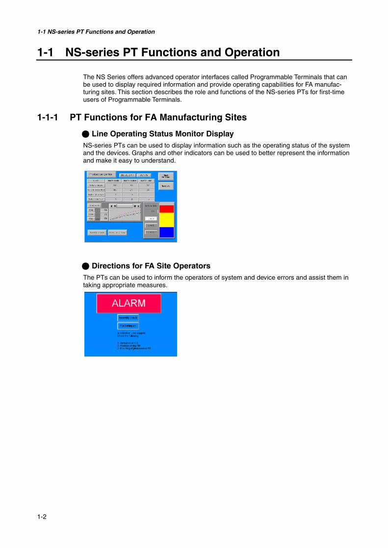
@ Line Operating Status Monitor DisplayNS-series PTs can be used to display information such as the operating status of the systemand the devices. Graphs and other indicators can be used to better represent the informationand make it easy to understand.
@ Directions for FA Site OperatorsThe PTs can be used to inform the operators of system and device errors and assist them intaking appropriate measures.

1-1 NS-series PT Functions and Operation
1-3
@ Control Panel SwitchesThe NS-series PTs allow the user to create various on-screen switches. By using touchswitch inputs, operating results can be sent to the host.
1-1-2 NS-series PT Operating System
@ Transferring Screen DataThe screen data displayed on NS-series PTs is created using the NS-Designer on a com-puter and transferred to the PT through RS-232C or Ethernet communications.
Note: Some models do not support Ethernet.
Screen data can also be transferred at high speed using a Memory Card.
RS-232C, Ethernet
Screen data
Create screen data.
Connect the computer to the PT onlywhen transferring screen data to or fromthe NS-Designer.
Computer(NS-Designer)
MemoryCard
Computer(NS-Designer)

1-1 NS-series PT Functions and Operation
1-4
@ Displaying ScreensThe information displayed on the screens is created using the NS-Designer on a computerand transferred to the PT. The required screens can be displayed by using commands fromthe host or touch switch operations.
@ Reading Data from the HostA communications method such as NT Link Ethernet or Controller Link is used to connect
the host, and the required data is automatically read from the host.Note: Some models do not support Ethernet or Controller Link.
@ Sending Data to the HostData input using touch switches (button ON/OFF status, numerals, and character strings) issent to the host.
Host
The required screens canbe displayed by usingcommands from the hostor touch switch operations.
Host
Touch panel
Host
ON/OFF status,numeric data, etc.
NT Link or Ethernet,Controller Link

1-2 Communications with the Host
1-5
1-2 Communications with the Host
NS-series PTs allow the user to allocate words and bits in any PLC area for use in accessingthe required display contents and storing input data.
Operations that can be performed include reading and writing allocated word contents andbit status directly, changing the display status of functional objects on the PT screen, andcontrolling and notifying PT status.
The NS-series PTs also enable communications with more than one PLC. A host name isregistered for each PLC connected, allowing access to any PLC areas by specifying the hostname and address.
When using NS-series PTs, the host can be connected using any of the following methods.
• 1:1 NT Link• 1:N NT Link (normal or high-speed)• Ethernet• Controller Link• Host Link
NS-series PT PLC
Timers/counters
DM Area I/O Area
Auxiliary Area

1-2 Communications with the Host
1-6
1-2-1 What is an NT Link?An NT Link is a method for high-speed communications between an OMRON PLC and anOMRON Programmable Terminal (PT) using a special protocol. In addition to a 1:1 NT Link,where a single PT is connected to a single PLC, NS-series PTs also support 1:N NT Links,allowing up to eight PTs to be connected to a single PLC port.
CS- and CJ-series PLCs can also be connected using high-speed 1:N NT Link communica-tions. For details on the PLCs that support high-speed 1:N NT Link communications, refer toAppendix 7 Standard Models.
In the rest of this manual, "NT Link" refers to NT Link communications in general, "1:1 NTLink" refers to an NT Link in a 1:1 configuration only, and "1:N NT Links" refers to NT Links ina 1:N configuration only. Where necessary, “normal 1:N NT Links” and “high-speed 1:N NTLinks” are used. When "1:N NT Links" is used alone, it refers to both normal and high-speedcommunications.
1-2-2 EthernetEthernet Units in PLCs that are supported by the NS-series PTs can be used to read andwrite data, word, and bit information simply. The use of FINS (Factory Interface NetworkService) message communications, one of OMRON’s standard communications services,enables high-speed communications without the need to be aware of the protocol.
For details on connection methods, refer to Section 5 Connecting to Host via Ethernet orController Link. For details on the PLCs that can be connected to the Ethernet, refer to Ap-pendix 7 Standard Models.
1-2-3 Controller LinkController Link is an FA network that can send and receive large data packets among OM-RON PLCs and FA computers. Controller Link Units for PLCs that are supported by the NS-series PTs connected to NS-CLK21 Controller Link Interface Units can be used to read andwrite data, word, and bit information simply.The Controller Link supports data links that enable data sharing and a message service thatenables sending and receiving data when required.
For details on connection methods, refer to Section 5 Connecting to Host via Ethernet orController Link. For details on the PLCs that can be connected using Controller Link, refer toAppendix 7 Standard Models.
1-2-4 Host LinkHost Link is a serial communications protocol for connecting an OMRON PT 1:1 to a host (aPLC) to read and write bits and words from the host. Host Link communications connect aPT to many different PLCs. Refer to the Host Connection Manual (Host Links) included onthe NS-Designer CD-ROM for connection methods and the PLCs for which Host Links canbe used.

1-3 System Configuration
1-7
1-3 System Configuration
The following information describes the system configuration using NS-series PTs. Refer toAppendix 8 Standard Models for details on available models.
1-3-1 Supported Peripheral Devices
Note 1: Only the following models support Ethernet: NS12-TS01(B), NS10-TV01(B), NS8-TV@1(B),and NS5-SQ01 (B).
Note 2: Only the following models support the Controller Link Interface Unit: NS12-TS0@, NS10-TV0@. (The NS8 and NS5 do not support the Controller Link Interface Unit.)
Note 3: The following models support the Video Input Unit: NS12-TS0@, NS10-TV0@, and NS8-TV@@. (The NS5 does not support the Video Input Unit.)
Note 4: The NS5-SQ0@ (B) does not have a USB port, so it cannot be connected directly to general-purpose printers.
• PTs (Refer to Appendix 7 Standard Models.)
• Recommended Bar Code Reader (Refer to page 3-12.) OMRON V520-RH21-6
• RS-232C/422A Converters OMRON NS-AL002 (non-insulated) (Refer to page A-13.)
OMRON NT-AL001 (insulated)
OMRON CJ1W-CIF11
Host
Bar Code ReaderRead bar codes astext string data.
RS-232C cable (15 m max.)RS-422A cable (500 m max.)RS-232C/422A Adapter
Ethernet cable (See note 1.)
Personal computerComputer runningWindows 95, 98, NT,Me, 2000, or XP
Memory CardSave screen data orthe system program orautomatically read dataat startup.
RS-232C cableEthernet cable(See note 1.)
Video camera orVision Sensor
Twisted-pair cable
Controller LinkInterface UnitEnables Con-troller Linkcommunicationswith a host. (Seenote 2.)
Printer (See note 4.)Connecting a general-purposecolor printer to the USB port on anNS-series PT makes it possible toprint out the current PT display.
NS-Designer
Video Input Unit(See note 3.)

1-3 System Configuration
1-8
• Recommended Memory Cards (Refer to page 3-18.) OMRON HMC-EF172 (15-MB flash memory)
OMRON HMC-EF372 (30-MB flash memory)
OMRON HMC-EF672 (64-MB flash memory)
• NS-Designer (Refer to NS-Designer Operation Manual (V074-E1-@)
NS-NSDC1-V@ (CD-ROM version)
Reference The following optional products are available. (Refer to page A-34.)Anti-reflection Sheets NS12-KBA04 (For NS12 and NS10)(5 sheets) NS7-KBA04 (For NS8)
NT30-KBA04 (For NS5)
Protective Covers NS12-KBA05 (For NS12 and NS10)(anti-reflection coating) NS7-KBA05 (For NS8)(5 covers) NT31C-KBA05 (For NS5)
Transparent Protective Covers NS12-KBA05N (For NS12 and NS10)(5 covers) NS7-KBA05N (For NS8)
NT31C-KBA05N (For NS5)
Chemical-resistant Cover NT30-KBA01 (For NS5)(1 cover)
Replacement Battery CJ1W-BAT01 (For NS12, NS10, NS8 and NS5)
• Video Input Unit (Refer to 3-7 Installing the Video Input Unit.)NS-CA001
NS-CA002: Refer to the NS Series RGB and Video Input Unit Operation Manual (Cat. No.V086).
• Controller Link Interface Unit (Refer to 3-8 Installing the Controller Link InterfaceUnit.)
NS-CLK21
• USB-compatible Printers (Refer to 3-5 Connecting to Printers.)
1-4 Procedure for Running NS-series PTs
1-9
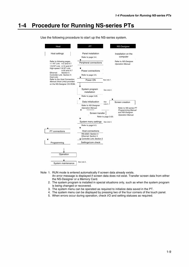
1-4 Procedure for Running NS-series PTs
Use the following procedure to start up the NS-series system.
Note 1. RUN mode is entered automatically if screen data already exists.An error message is displayed if screen data does not exist. Transfer screen data from eitherthe NS-Designer or a Memory Card.
2. The system program is installed in special situations only, such as when the system programis being changed or recovered.
3. The system menu can be operated as required to initialize data saved in the PT.4. The system menu can be displayed by pressing two of the four corners of the touch panel.5. When errors occur during operation, check I/O and setting statuses as required.
Host PT NS-Designer
Host settings Panel installation Installation on thecomputer
Refer to following pages.1:1 NT Link: 4-2 and A-71:N NT Link: 4-10 and A-7High-speed 1:N NT Link:
4-20 and A-7Ethernet: Section 5Controller Link: Section 5Host Link:Refer to the Host ConnectionManual (Host Links) providedon the NS-Designer CD-ROM.
Screen transfer
Peripheral connections
Power connections
Power ON
System programinstallation
Data initialization Screen creation
System menu settings
Host connections
Settings/com check
Operation
System maintenance
PT connections
Programming
Refer to NS-DesignerOperation Manual.
Refer to NS-series PTProgramming Manualand NS-DesignerOperation Manual.
Refer to page 3-20.
Refer to NS-DesignerOperation Manual.
Refer to page 6-3.
RS-232C: Section 4Ethernet: Section 5Controller Link: Section 5
Refer to page 3-20.
Refer to page 3-4.
Refer to page 3-5.
See note 1.
See note 2.
Seenote 3.
See note 4.
See note 5.

1-4 Procedure for Running NS-series PTs
1-10
The following table lists the device and software manuals used for reference.
Device/Software Manual name Catalog No.Setup Manual(Provides information on existing NS-series models, i.e.,NS12, NS10, and NS7.)
V072
Programming Manual V073Macro Reference Provided with NS-
Designer
NS-series PTs
Tutorial Provided with NS-Designer
NS-Designer NS-Designer Operation Manual V074NS-series LadderMonitor
NS-series Ladder Monitor Operation Manual Provided with NS-series Ladder Monitor
SYSMAC C200HS Installation Guide W236SYSMAC C200HS Operation Manual W235SYSMAC C200HX/HG/HE(-Z) Installation Guide W302SYSMAC C200HX/HG/HE Operation Manual W303SYSMAC C200HX/HG/HE(-ZE) Operation Manual W322SYSMAC CQM1 Operation Manual W226SYSMAC CQM1H Operation Manual W363SYSMAC CV Series CV500/CV1000/CV2000/CVM1Programming Manual: Ladder Diagrams
W202
SYSMAC CPM1A Operation Manual W317SYSMAC CPM2A Operation Manual W352SYSMAC CPM1/CPM1A/CPM2A/CPM2C/SRM1(-V2)Programming Manual
W353
SYSMAC CPM2C Operation Manual W356SYSMAC CJ Series Operation Manual W393SYSMAC CS/CJ Series Serial Communications Unitand Board Operation Manual
W336
SYSMAC CS Series Operation Manual W339SYSMAC CS/CJ Series Programming Manual W394SYSMAC CS/CJ Series Instruction Reference Manual W340SYSMAC CS/CJ Series Programming Console Opera-tion Manual
W341
PLC
SYSMAC CS/CJ Series Communications CommandReference Manual
W342
SYSMAC Support Software Operation Manual: C-seriesPLCs
W248
SYSMAC Support Software Operation Manual: CVM1PLCs
W249
SYSMAC CPT Operation Manual W333
ProgrammingDevices/Software
CX-Programmer User Manual W437SYSMAC CS/CJ Series Ethernet Unit Operation Manual W343SYSMAC CVM1/CV Series Ethernet Unit System Man-ual
W242
FINS Command Reference Manual W227SYSMAC CS and CJ Series Ethernet Units OperationManual Construction of Networks
W420
Ethernet Unit
SYSMAC CS and CJ Series Ethernet Units OperationManual Construction of Applications
W421
Controller Link Support Board Operation Manual W307Controller Link Sup-port Board Controller Link Support Board for PCI Bus Operation
ManualW383
Controller Link Unit Controller Link Unit Operation Manual W309

Section 2
Before Connecting
This section provides information on methods for connecting NS-series PTs that must be under-stood before connecting the host and peripheral devices.
2-1 Connecting the Host ........................................................................................................ 2-2
2-1-1 Communications Types and Connection Methods ................................................... 2-2
2-2 Part Names and Functions ............................................................................................... 2-7
2-1 Connecting the Host
2-2
2-1 Connecting the Host
This section provides details on the networks for hosts that can be used with NS-series PTs.
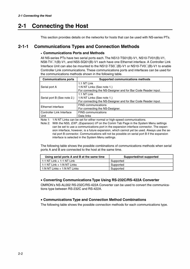
2-1-1 Communications Types and Connection Methods• Communications Ports and MethodsAll NS-series PTs have two serial ports each. The NS12-TS01(B)-V1, NS10-TV01(B)-V1,NS8-TV@1(B)-V1, and NS5-SQ01(B)-V1 each have one Ethernet interface. A Controller LinkInterface Unit can also be mounted to the NS12-TS0@(B)-V1 or NS10-TV0@(B)-V1 to enableController Link communications. These communications ports and interfaces can be used forthe communications methods shown in the following table.
Communications ports Supported communications methods
Serial port A1:1 NT Link1:N NT Links (See note 1.)For connecting the NS-Designer and for Bar Code Reader input.
Serial port B (See note 2.)1:1 NT Link1:N NT Links (See note 1.)For connecting the NS-Designer and for Bar Code Reader input.
Ethernet interfaceFINS communicationsFor connecting the NS-Designer.
Controller Link InterfaceUnit
FINS communicationsData links
Note 1: 1:N NT Links can be set for either normal or high-speed communications.Note 2: With the NS5, EXP. (Expansion) I/F on the Comm Tab Page in the System Menu settings
can be set to use a communications port in the expansion interface connector. The expan-sion interface, however, is a future expansion, which cannot yet be used. Always use the se-rial port B connector. Communications will not be possible on serial port B if the expansioninterface is selected in the System Menu settings.
The following table shows the possible combinations of communications methods when serialports A and B are connected to the host at the same time.
Using serial ports A and B at the same time Supported/not supported1:1 NT Link + 1:1 NT Link Supported1:1 NT Link + 1:N NT Links Supported1:N NT Links + 1:N NT Links Supported
• Converting Communications Type Using RS-232C/RS-422A ConverterOMRON’s NS-AL002 RS-232C/RS-422A Converter can be used to convert the communica-tions type between RS-232C and RS-422A.
• Communications Type and Connection Method CombinationsThe following table shows the possible connection methods for each communications type.

2-1 Connecting the Host
2-3
1:1 Connection
Supported communicationsmethods
PTcommu-nications
type
Hostcommu-nications
type
Supported connection methods1:1 NTLink
1:N NTLinks
FINSDataLinks
Refer-encepage
RS-232CRS-232C cable
HostPT
Yes Yes No NoP.4-2P.4-10
RS-232C
RS-422ANS-AL002Converter
HostPT
RS-422A cable
Yes Yes No NoP.4-2P.4-10
Ethernet Ethernet
HostPT
Ethernet
10Base-T/100Base-T twisted-pair crosscable
No No Yes No P.5-2
ControllerLink (Seenote.)
ControllerLink
Controller LinkInterface Unit HostPT
Specified shielded twisted-paircable No No Yes Yes P. 5-15
Yes: Connection is possible. No: Connection is not possible.Note: Only when a Controller Link Interface Unit (NS-CLK21) is mounted.

2-1 Connecting the Host
2-4
1:N Connection (Connecting Multiple PTs to a Single Host)
Supported communicationsmethods
PTcommu-nications
type
Hostcommu-nications
type
Supported connection methods1:1 NTLink
1:N NTLinks
FINSDataLinks
Refer-encepage
RS-232C RS-422A
HostPTsNS-AL002Adapter
RS-422A cable
No Yes No No P.4-10
Ethernet Ethernet
Host
PTs
Ethernet
HUB10Base-T/100Base-T
twisted-pair straight cable
No No Yes No P.5-2
ControllerLink (Seenote.)
ControllerLink
HostPTs Controller LinkInterface Unit
Specified shieldedtwisted-pair cable
No No Yes Yes P. 5-15
Yes: Connection is possible. No: Connection is not possible.Note: Only when a Controller Link Interface Unit (NS-CLK21) is mounted.

2-1 Connecting the Host
2-5
N:1 Connection (Connecting Multiple Hosts to a Single PT)
Supported communicationsmethods
PTcommu-nications
type
Hostcom-
munica-tionstype
Supported connection methods1:1 NTLink
1:N NTLinks
FINSDataLinks
Refer-encepage
RS-232C RS-232C
Host
PT
Serial port A
RS-232C cable
Host
Serial port B
RS-232C cable
Yes Yes No No
P.4-2P.4-10
Ethernet Ethernet
HostPT
Host
HUBEthernet10Base-T/100Base-Ttwisted-pair straight cable No No Yes No
P.5-2
ControllerLink (Seenote.)
Control-ler Link
HostPT
Host
Controller LinkInterface Unit
Specified shieldedtwisted-pair cable
No No Yes Yes P. 5-15
RS-232CRS-232C,RS-422A
Host
PT
Serial port A
RS-232C cable
Host
Serial port B
NS-AL002RS-232C/RS-422AConverter
RS-422A cable
An RS-422A line can be connected toserial port A at the same time that an RS-232C line is connected to serial port B.
Yes Yes No ---P.4-2P.4-10
Ethernet,RS-232C
Ethernet,RS-232C
HostPT
Ethernet
Host
RS-232C cable
10Base-T/100Base-Ttwisted-pair cross cable
Yes Yes Yes ---P.4-2P.4-10P.5-2

2-1 Connecting the Host
2-6
Supported communicationsmethods
PTcommu-nications
type
Hostcom-
munica-tionstype
Supported connection methods1:1 NTLink
1:N NTLinks
FINSDataLinks
Refer-encepage
RS-232C,ControllerLink
RS-232C,Control-ler Link
Host
PT
Serial port A
RS-232C cable
Host
Controller Link
Controller LinkInterface Unit
Specified shielded twisted-pair cable
Yes Yes Yes YesP.4-2P.4-10P.5-15
Ethernet,ControllerLink
Ethernet,Control-ler Link
HostPT
Ethernet
Host
Specified shielded twisted-pair cable
10BASE-T/100BASE-TTwisted-pair cross cable
Controller LinkInterface Unit
Controller Link
No No Yes Yes P.5-2P.5-15
Yes: Connection is possible. No: Connection is not possible.Note: Only when a Controller Link Interface Unit (NS-CLK21) is mounted.
• The NS-AL002 is connected directly to the serial port of the PT and power is suppliedfrom pin 6 of the port.
• When there are multiple serial ports and Ethernet Units for a single host, each port canbe used to communicate with separate PTs. This type of communications method,however, will reduce the communications performance at the host.
2-2 Part Names and Functions
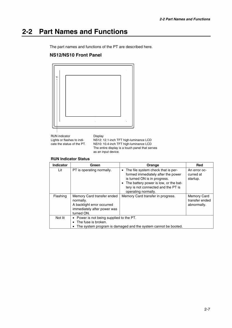
2-7
2-2 Part Names and Functions
The part names and functions of the PT are described here.
NS12/NS10 Front Panel
RUN Indicator Status
Indicator Green Orange RedLit PT is operating normally. • The file system check that is per-
formed immediately after the poweris turned ON is in progress.
• The battery power is low, or the bat-tery is not connected and the PT isoperating normally.
An error oc-curred atstartup.
Flashing Memory Card transfer endednormally.A backlight error occurredimmediately after power wasturned ON.
Memory Card transfer in progress. Memory Cardtransfer endedabnormally.
Not lit • Power is not being supplied to the PT.• The fuse is broken.• The system program is damaged and the system cannot be booted.
RUN indicatorLights or flashes to indi-cate the status of the PT.
DisplayNS12: 12.1-inch TFT high-luminance LCDNS10: 10.4-inch TFT high-luminance LCDThe entire display is a touch panel that servesas an input device.

2-2 Part Names and Functions
2-8
NS12/NS10 Rear Panel Switches
Note Confirm system safety before turning the power ON/OFF or restarting. Otherwise the systemmay operate unpredictably.
Expansion Interface ConnectorUsed to mount the Video InputUnit or the Controller LinkInterface Unit.
Reset SwitchUsed to initialize the PT.The status of screen data,other registered data, andthe system menu, however,will not change.
Serial Port A ConnectorUsed to connect the host, NS-Designer, and BarCode Reader. Uses an RS-232C 9-pinconnector.
Battery CoverThe battery is installedunderneath the cover.
Ethernet ConnectorUsed to connect the Ethernetcable. Uses a 10Base-T/100Base-T 8-pin modularplug.
DIP SwitchUsed to set the settings fortransmitting data using theMemory Card.
Memory Card ConnectorUsed to connect thememory card for storingand transmitting screendata, log data, and systemprograms.
Serial Port B ConnectorUsed to connect the host, NS-Designer, and Bar Code Reader.Uses an RS-232C 9-pin connector.
USB Slave ConnectorThis is a USB Type B connector.(It cannot be used with NS Ver. 4,Ver. 5, or Ver. 6. systems)
USB Host ConnectorUsed to connect to printers. Itis a USB Type A connector.
FG TerminalUsed to preventmalfunctions due tonoise interference.
Main Circuit DCInput TerminalsUsed to connectthe power supply.
Power Input Terminal Block CoverCovers the power input terminal block.

2-2 Part Names and Functions
2-9
NS8 Front Panel
RUN Indicator Status
Indicator Green Orange RedLit PT is operating normally. • The file system check that is
performed immediately after thepower is turned ON is inprogress.
• The battery power is low, or thebattery is not connected and thePT is operating normally.
An erroroccurred atstartup.
Flashing Memory Card transfer endednormally.
Memory Card transfer in progress. Memory Cardtransfer endedabnormally.
Not lit • Power is not being supplied to the PT.• The fuse is broken.• The system program is damaged and the system cannot be booted.
Display8.4-inch TFT high-luminance colorLCDThe entire display is a touch panelthat serves as an input device.
RUN indicatorLights or flashes to indicate thestatus of the PT.

2-2 Part Names and Functions
2-10
NS8 Rear Panel
Note Confirm system safety before turning the power ON/OFF or restarting. Otherwise the systemmay operate unpredictably.
Expansion Interface ConnectorUsed to mount the Video InputUnit or the Controller LinkInterface Unit.
Reset SwitchUsed to initialize the PT.The status of screen data,other registered data, andthe system menu, however,will not change.
Serial Port A ConnectorUsed to connect the host, NS-Designer, and BarCode Reader. Uses an RS-232C 9-pinconnector.
Battery CoverThe battery is installedunderneath the cover.
Ethernet ConnectorUsed to connect the Ethernet cable.Uses a 10Base-T/100Base-T 8-pinmodular plug.
DIP SwitchUsed to set the settings fortransmitting data using theMemory Card.
Memory Card ConnectorUsed to connect thememory card for storingand transmitting screendata, log data, and systemprograms.
Serial Port B ConnectorUsed to connect the host, NS-Designer, and Bar Code Reader.Uses an RS-232C 9-pin connector.
USB Slave ConnectorThis is a USB Type B connector.(It cannot be used with NS Ver. 4,Ver. 5, or Ver. 6 systems.)
USB Host ConnectorUsed to connect to printers. Itis a USB Type A connector.
FG TerminalUsed to preventmalfunctions due to noiseinterference.
Main Circuit DCInput TerminalsUsed to connectthe power supply.
Power Input Terminal Block CoverCovers the power input terminal block.

2-2 Part Names and Functions
2-11
NS5 Front Panel
RUN Indicator Status
Indicator Green Orange RedLit PT is operating normally. • The file system check that is
performed immediately after thepower is turned ON is inprogress.
• The battery power is low, or thebattery is not connected and thePT is operating normally.
An erroroccurred atstartup.
Flashing Memory Card transfer endednormally.
Memory Card transfer in progress. Memory Cardtransfer endedabnormally.
Not lit • Power is not being supplied to the PT.• The fuse is broken.• The system program is damaged and the system cannot be booted.
RUN indicatorLights or flashes to indicate thestatus of the PT.
Display5.7-inch STN color LCDThe entire display is a touch panelthat serves as an input device.Colors may be lighter toward the edgeof the screen.This is characteristic of STN displaysand not an error.
2-2 Part Names and Functions
2-12
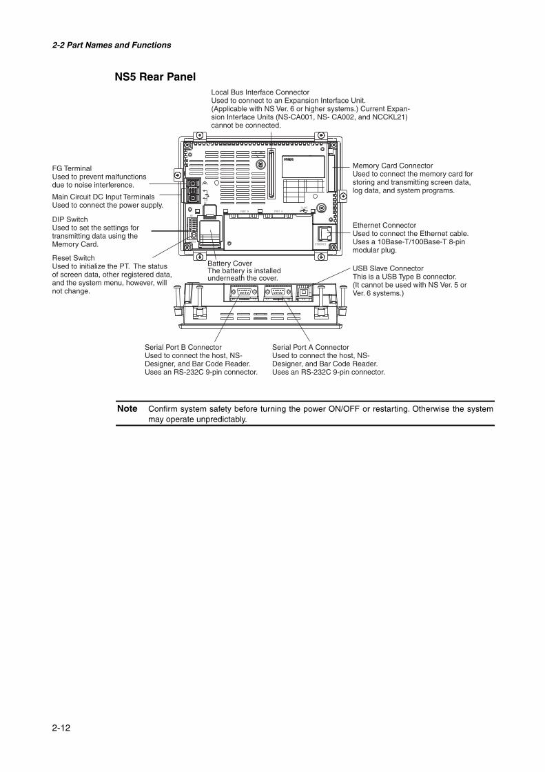
NS5 Rear Panel
Note Confirm system safety before turning the power ON/OFF or restarting. Otherwise the systemmay operate unpredictably.
FG TerminalUsed to prevent malfunctions due to noise interference.
Main Circuit DC Input TerminalsUsed to connect the power supply.
DIP SwitchUsed to set the settings for transmitting data using the Memory Card.
Reset SwitchUsed to initialize the PT. The status of screen data, other registered data, and the system menu, however, will not change.
Battery CoverThe battery is installed underneath the cover.
Serial Port B ConnectorUsed to connect the host, NS-Designer, and Bar Code Reader. Uses an RS-232C 9-pin connector.
Serial Port A ConnectorUsed to connect the host, NS-Designer, and Bar Code Reader. Uses an RS-232C 9-pin connector.
Local Bus Interface ConnectorUsed to connect to an Expansion Interface Unit. (Applicable with NS Ver. 6 or higher systems.) Current Expan-sion Interface Units (NS-CA001, NS- CA002, and NCCKL21) cannot be connected.
Memory Card ConnectorUsed to connect the memory card for storing and transmitting screen data, log data, and system programs.
Ethernet ConnectorUsed to connect the Ethernet cable. Uses a 10Base-T/100Base-T 8-pin modular plug.
USB Slave ConnectorThis is a USB Type B connector. (It cannot be used with NS Ver. 5 or Ver. 6 systems.)

2-2 Part Names and Functions
2-13
Touch PanelThe touch switches on the front panel of the PT are used to perform input operations. Pressthe touch switches to perform operations such as switching screens and sending bit status tothe host.
Functionperformed
When a functional object is pressed, its function is performed.
Functional objects can be created combiningminimum size switches.
Minimum Switch SizeNS12: 16 dots (4.92 mm) × 16 dots (4.92 mm)NS10: 16 dots (5.3 mm) × 16 dots (5.3 mm) NS8: 20 dots (4.92 mm) × 20 dots (4.92 mm)NS5: 16 dots (5.8 mm) × 16 dots (5.8 mm)
To ensure correct input operations, create touch switches so that they consist of at least twoswitches horizontally and vertically.
Note • Press the touch switches with a pressure of 30 N max.• Do not press the touch switches when the backlight is not lit or when there is no display.• Check system safety before pressing the touch switches.• Inputs may not be recognized if the touch switches are pressed in rapid succession. Check
that one input operation has finished before performing the next one.
Reference • Pressing Three Switches Simultaneously
When the positions of multiple touch switches are set as shown in the example andthree switches are pressed simultaneously, the touch switches will malfunction due tostructural characteristics.
Position the touch switches carefully. In the example shown below, switches havebeen created in positions A and B, and at points C and D, where the vertical and hori-zontal lines through A and B intersect.
A C
D BMinimum touch switch frame
• If touch switches A, B, and C are turned ONsimultaneously, switch D may also turn ONdue to the structure of the touch panel.
• In the same way, if touch switches A, B,and D are turned ON simultaneously, switchC may also turn ON.
2-2 Part Names and Functions
2-14
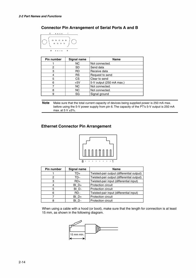
Connector Pin Arrangement of Serial Ports A and B
Pin number Signal name Name1 NC Not connected.2 SD Send data3 RD Receive data4 RS Request to send5 CS Clear to send6 +5V 5-V output (250 mA max.)7 NC Not connected.8 NC Not connected.9 SG Signal ground
Note Make sure that the total current capacity of devices being supplied power is 250 mA max.before using the 5-V power supply from pin 6. The capacity of the PT's 5-V output is 250 mAmax. at 5 V ±5%.
Ethernet Connector Pin Arrangement
Pin number Signal name Name1 TD+ Twisted-pair output (differential output)2 TD− Twisted-pair output (differential output)3 RD+ Twisted-pair input (differential input)4 BI_D+ Protection circuit5 BI_D− Protection circuit6 RD− Twisted-pair input (differential input)7 BI_D+ Protection circuit8 BI_D− Protection circuit
When using a cable with a hood (or boot), make sure that the length for connection is at least15 mm, as shown in the following diagram.
15 mm min.

Section 3
Installing the PT and ConnectingPeripheral DevicesThis section describes the methods used to install the PT and connect peripheral devices.For details on methods for connecting the host, refer to Section 4 Connecting the Host to the Se-rial Port or Section 5 Connecting to Host via Ethernet or Controller Link.
3-1 Installing the PT............................................................................................................... 3-33-1-1 Installation Environment........................................................................................... 3-33-1-2 Installing RS-232C/RS-422A Converters ................................................................. 3-43-1-3 Mounting the PT to the Control Panel ...................................................................... 3-43-1-4 Connecting the Power Supply................................................................................... 3-53-1-5 Wiring the Ground Wire........................................................................................... 3-73-1-6 Peripheral Device Connection Limitations ............................................................... 3-7
3-2 Starting the PT ................................................................................................................. 3-83-2-1 Operation at Startup.................................................................................................. 3-83-2-2 Starting the PT for the First Time........................................................................... 3-10
3-3 Connecting the NS-Designer.......................................................................................... 3-123-4 Connecting to Bar Code Readers ................................................................................... 3-13
3-4-1 Connection Methods............................................................................................... 3-133-4-2 Setting Bar Code Readers....................................................................................... 3-143-4-3 Data Format ............................................................................................................ 3-153-4-4 Bar Code Input ....................................................................................................... 3-15
3-5 Connecting to Printers.................................................................................................... 3-163-5-1 Connection Method ................................................................................................ 3-16
3-6 Using Memory Cards ..................................................................................................... 3-173-6-1 Installation .............................................................................................................. 3-183-6-2 Replacing System Programs ................................................................................... 3-193-6-3 Transferring Data with Memory Cards ................................................................... 3-19
3-7 Installing the Video Input Unit ...................................................................................... 3-263-7-1 Video Input Unit Components................................................................................ 3-263-7-2 Nomenclature and Functions .................................................................................. 3-27

3-7-3 Installation Method for Video Input Unit ............................................................... 3-283-7-4 Connecting to Video Input Connectors................................................................... 3-33
3-8 Installing the Controller Link Interface Unit.................................................................. 3-383-8-1 Controller Link Interface Unit Components ........................................................... 3-383-8-2 Nomenclature and Functions .................................................................................. 3-393-8-3 Installation Method for Controller Link Interface Unit .......................................... 3-423-8-4 Wiring..................................................................................................................... 3-49

3-1 Installing the PT
3-3
Note When unpacking the PT and peripheral devices, check for any external damage. Shake theproduct gently and check for any abnormal sounds.
3-1 Installing the PTThe methods used to mount the PT to the control panel and connect the power supply aredescribed here.
3-1-1 Installation EnvironmentAlways mount the PT to the control panel and perform other installation procedures accordingto the following precautions.
Note Do not install the PT in any of the following locations:• Locations subject to extreme temperature changes.• Locations subject to temperatures or humidity outside the ranges in the specifications.• Locations subject to high humidity that may result in condensation.• Locations that would subject the PT to chemicals.• Locations that would subject the PT to oil.• Locations subject to corrosive or flammable gases.• Locations that would subject the PT to direct shock or vibration.• Locations that would directly expose the PT to wind or rain.• Locations subject to strong ultraviolet light.
Provide proper shielding measures when installing in the following locations:• Locations subject to static electricity or other sources of noise.• Locations subject to strong electromagnetic fields.• Locations near to power supply lines.• Locations subject to possible exposure to radiation.

3-1 Installing the PT
3-4
3-1-2 Installing RS-232C/RS-422A ConvertersWhen using RS-232C/RS-422A Converters, mount the PT to the control panel before install-ing these Units.
For details on installing and removing RS-232C/RS-422A Converters, refer to Appendix 4Using NS-AL002 RS-232C/RS-422A Converters.
3-1-3 Mounting the PT to the Control PanelThe PT is flush-mounted to the control panel.
The PT is mounted using the panel mounting brackets provided with the PT, and tools, suchas a Phillips screwdriver.
Use the following procedure to mount the PT to the control panel.
1. Make a hole in the panel for flush mounting according to the following dimensions and in-sert the PT from the front of the panel.
横
縦
Model Dimensions
NS12 Width 302 +10 × Height 228 +1
0 mm
NS10 Width 302 +10 × Height 228 +1
0 mm
NS8 Width 220.5 +0.50 × Height 165.5 +0.5
0 mm
NS5 Width 184 +0.50 × Height 131 +0.5
0 mm
Width
Height
Recommended panel thickness:1.6 to 4.8 mm
3-1 Installing the PT
3-5
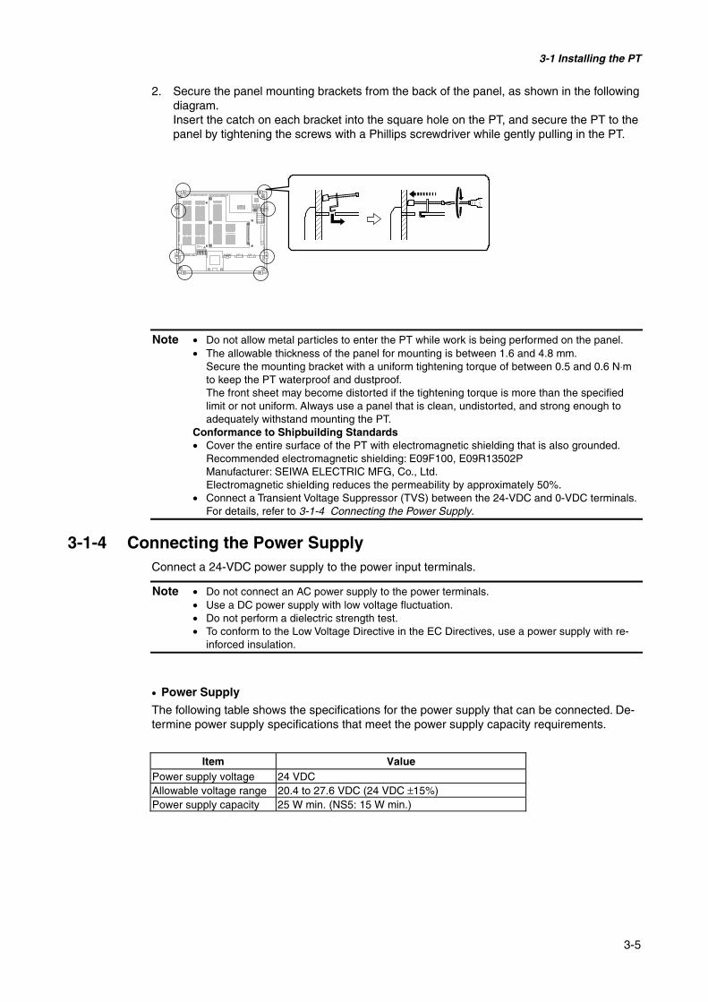
2. Secure the panel mounting brackets from the back of the panel, as shown in the followingdiagram.Insert the catch on each bracket into the square hole on the PT, and secure the PT to thepanel by tightening the screws with a Phillips screwdriver while gently pulling in the PT.
Note • Do not allow metal particles to enter the PT while work is being performed on the panel.• The allowable thickness of the panel for mounting is between 1.6 and 4.8 mm.
Secure the mounting bracket with a uniform tightening torque of between 0.5 and 0.6 N⋅mto keep the PT waterproof and dustproof.The front sheet may become distorted if the tightening torque is more than the specifiedlimit or not uniform. Always use a panel that is clean, undistorted, and strong enough toadequately withstand mounting the PT.
Conformance to Shipbuilding Standards• Cover the entire surface of the PT with electromagnetic shielding that is also grounded.
Recommended electromagnetic shielding: E09F100, E09R13502PManufacturer: SEIWA ELECTRIC MFG, Co., Ltd.Electromagnetic shielding reduces the permeability by approximately 50%.
• Connect a Transient Voltage Suppressor (TVS) between the 24-VDC and 0-VDC terminals.For details, refer to 3-1-4 Connecting the Power Supply.
3-1-4 Connecting the Power SupplyConnect a 24-VDC power supply to the power input terminals.
Note • Do not connect an AC power supply to the power terminals.• Use a DC power supply with low voltage fluctuation.• Do not perform a dielectric strength test.• To conform to the Low Voltage Directive in the EC Directives, use a power supply with re-
inforced insulation.
• Power Supply
The following table shows the specifications for the power supply that can be connected. De-termine power supply specifications that meet the power supply capacity requirements.
Item ValuePower supply voltage 24 VDCAllowable voltage range 20.4 to 27.6 VDC (24 VDC ±15%)Power supply capacity 25 W min. (NS5: 15 W min.)

3-1 Installing the PT
3-6
• Parts Used to Connect the Power Supply
Note Connect power to the power terminal block using twisted-pair power lines with a cross-sectional area of at least 2 mm
2 and always using M3.5 crimp terminals.The correct tightening torque for the terminal block is 0.8 N⋅m. Tighten terminal block screwsproperly.
• Recommended Products
ManufacturerModel number offorked terminals
Model number ofround terminals
Applicable powerlines (twisted-pair)
J.S.T. Mfg. Co., Ltd. 2-YS3A 2-3.5Fuji Terminal Industry Co., Ltd. 2-YAS3.5 V2-S3.5Nichifu Terminal Industries Co., Ltd. 2Y-3.5 2-3.5
2.0 to 2.63 mm2
Note When surge noise occurs in the DC power supply, connect a Transistor Voltage Suppressor(TVS) between the 24-V and 0-V DC terminals.Recommended TVS model: 1.5KE33CAManufacturers: Vishay Intertechnology Inc, STMicroelectronics
24 VDC
TVS
Forked type Round type
7 mm max. 7 mm max.
24 VDC
Breaker
Functional ground
Breaker
Functional ground
24 VDCpower supply
24 VDCpower supply
24 VDC
NS12, 10, 8 NS5
3-1 Installing the PT
3-7
3-1-5 Wiring the Ground WireThe PT is provided with a functional ground (FG: ) terminal.
Wire the FG terminal according to the following conditions.
1. Ground according to Figure when there is difference in potential between the PT andhost. Do not ground the functional ground of the PT if it is far from the host and one-pointgrounding is difficult.
2. Do not ground the functional ground (FG: ) of the PT if it is mounted to the same panelas devices that generate noise, such as motors and inverters.
Note Ground correctly to prevent malfunctions caused by noise.
3-1-6 Peripheral Device Connection LimitationsSelect one of the following combinations when devices requiring power supply are connectedto port A, port B, and an Expansion Interface Unit on the PT. Use a 5-V Bar Code Readerwith a current consumption of 250 mA or the equivalent.
Port A and B connection combinations Expansion Interface Unit(NS-CA001, NS-CLK21)
When a Bar Code Reader and the NS-AL002 are connected toports A and B at the same time
Cannot be used
When a Bar Code Reader and the CJ1W-CIF11 are connectedto ports A and B at the same time
Cannot be used
When a Bar Code Reader and the NT-AL001 are connected toports A and B at the same time
Cannot be used
When the CJ1W-CIF11 and C1W-CIF11 are connected to portsA and B at the same time
Can be used
When the CJ1W-CIF11 and NS-AL002 are connected to ports Aand B at the same time
Can be used
When the CJ1W-CIF11 and NT-AL001 are connected to ports Aand B at the same time
Cannot be used
When two NT-AL001s are connected to ports A and B at thesame time
Cannot be used
When a Bar Code Reader is connected to port A or B Can be usedWhen the CJ1W-CIF11 is connected to port A or B Can be usedWhen the NS-AL002 is connected to port A or B Can be usedWhen the NT-AL001 is connected to port A or B Can be used
PT Host
One-pointgrounding

3-2 Starting the PT
3-8
3-2 Starting the PT
Check that the hardware is connected properly, turn ON the power to the PT, and then startthe PT.
Use the following procedure to start the PT.
3-2-1 Operation at StartupWhen the power is ON or the PT is reset, the PT will operate as follows:
Indicator lights orange.
Immediately after the power is turned ON, the indicator will light orange.The file system will be checked and the system recovered if the power was turned OFFwhile a file was being written in previous operation, or if the battery capacity was low anddrive safety information from the system program area screen data area could not be saved.
↓
Indicator lights green.
When the system starts properly, the indicator will light green.If the indicator does not light green, the system programs may be damaged. Contact yournearest OMRON representative.
↓
Startup message is displayed.
A message about the startup status will be displayed.If an error occurs, the PT will stop startup procedures and display a message. (Refer to Sec-tion 5 Troubleshooting in the Programming Manual.)If an error occurs that allows startup to continue, a warning will be displayed. When a warn-ing is displayed, the PT will enter standby state and wait for touch input. Check the messageand then touch the screen. The PT will continue with startup procedures.
3-2 Starting the PT
3-9
↓
PT starts operating
The PT goes into RUN mode and starts operating according to the screen data in the PT.
When the PT is connected using communications conditions other than the set conditions, amessage “Connecting…” will be displayed at the bottom right of the screen, and the PT willbe in standby status until normal connection is established.
To change the communications settings, display the System Menu and change the settings.
Note Confirm the safety of the system before turning the power ON and OFF or pressing the resetswitch.
3-2 Starting the PT
3-10
3-2-2 Starting the PT for the First TimeAlways perform the following operations when turning ON the PT for the first time after pur-chase.
1. Language selection.2. Set the date and time.
Operate according to the following conditions.
a) When the power is turned ON to the PT, the following error message will be displayed. Press theOK Button.
b) The System Menu will be displayed. Press the Initialize Tab. The dialog boxes and System Menuare set for English-language displays at the factory. The language can be changed to Japanese atthis point if desired. To change to Japanese, select it and then press the Write Button. The follow-ing message will be displayed. Press the Yes Button. Do not turn OFF the power supply until thelanguage change process has been completed.
c) Next, select the PT Tab. Set the time and date.
d) Press the date display area under the heading Date and Time. A dialog box will be displayed. Inputthe date in yyyy/mm/dd format.

3-2 Starting the PT
3-11
Example: Input March 15, 2002 as 2002.3.15.
e) Press the time display area under the heading Date and Time. A dialog box will be displayed. Inputthe time using a 24-hour clock in hours/minutes/seconds format.Example: Input 06:01:01 p.m. as 18.1.1.The Write Button will be displayed, but the time and date settings will be enabled immediately afterthey have been input in the dialog box.This completes the procedure required to start the PT for the first time. Now transfer the projectdata. Refer to 3-6 Using Memory Cards and Section 10 Transferring Data to and from PTs in theNS-Designer Operation Manual.
3-3 Connecting the NS-Designer
3-12
3-3 Connecting the NS-Designer
Use an RS-232C or Ethernet cable to connect the PT and computer so that screen data thathas been created with the NS-Designer can be transferred to the PT.
Connect the RS-232C cable from the computer to serial port A or B. The cable can be con-nected to either serial port A or B.
PTs can also be connected to the computer via Ethernet, or modem to transfer screen data.
• Communications Conditions
The communications conditions are set with the CX-Server. For details, refer to Section 10Transferring Data to and from PTs in the NS-Designer Operation Manual.
• Recommended Connecting Cables
Use the following cables when connecting via RS-232C.
XW2Z-S002 (OMRON, cable length: 2 m)(D-Sub male 9-pin and D-Sub female 9-pin, for IBM PC/AT or compatible computersand NX computers in the PC-9800 Series)
For details on preparing connecting cables, refer to Appendix 4 Preparing Connecting Ca-bles.
Reference When connecting two computers in series to a single PT, data cannot be transferred using theserial cables.Example: When a PT is connected in series to the computer’s COM1 and COM2 ports.
PT
Computer
Serial port A Serial port B
Computer

3-4 Connecting to Bar Code Readers
3-13
3-4 Connecting to Bar Code Readers
Connecting a Bar Code Reader to the PT allows bar code data to be read as characterstrings in the character string input areas.
For details on methods for inputting character strings from a Bar Code Reader, refer to 3-6Inputting Numeral and Character Strings in the Programming Manual.
3-4-1 Connection MethodsConnect the Bar Code Reader to either serial port A or B of the PT as shown in the followingdiagram.
Recommended Bar Code Reader:V520-RH21-6, manufactured by OMRON.
Note Always turn OFF the power to the Bar Code Reader and the PT before connecting or discon-necting cables.
Prepare the connecting cables, referring to Appendix 7 Preparing Connecting Cables for BarCode Readers.
Reference Bar Code Readers cannot be connected to both serial ports A and B at the same time.
PT
Bar Code Reader
9-pin connector Serial port A or B(RS-232C, 9-pin)
Connecting cable Bar Code Readercable

3-4 Connecting to Bar Code Readers
3-14
3-4-2 Setting Bar Code ReadersThe Bar Code Reader’s communications conditions and other settings can be set from eitherthe NS-Designer or the PT.
@ Setting from the NS-DesignerUse the NS-Designer to set PT settings, such as the conditions for communications with theBar Code Reader, according to the following table. Set the communications conditions sup-ported by the Bar Code Reader to suit the application environment.
Item Settings DefaultData bits 7 or 8 bits 7 bitsStop bits 1 or 2 bits 2 bitsParity None, odd, or even EvenCommunicationsSpeed
4,800, 9,600, or 19,200 bps 9,600 bps
Input method Manual or Auto Auto
@ Setting from the PTSet the communications conditions from the System Menu.
For details on specific methods for operating the System Menu, refer to 6-6-6 Bar CodeReader Settings.
@ Bar Code Reader SettingsSet the settings for the Bar Code Reader according to the following table. Make sure, how-ever, that the communications conditions settings for the communications speed, parity, stopbits, and data bits, match those set for the PT. For details on setting methods, refer to the op-eration manual of the Bar Code Reader being used.
Item SettingsCommunications Speed 4,800, 9,600, or 19,200 bpsParity Even, odd, or none.Stop bits 1 or 2 bitsData bits 7 or 8 bitsPreamble STXPostamble ETXRS/CS control InvalidCommunications protocol No protocol modeBar code label digit transfer Transfer prohibited.ID character transfer Transfer prohibited.Bar code types Multi-read (reads everything)Trigger switch setting Automatic read mode

3-4 Connecting to Bar Code Readers
3-15
3-4-3 Data FormatUse the following data format for communications using the PT’s bar code input function.
STX Data Data Data ETX(02H) (03H)
The supported data characters are 20H to 7FH hexadecimal and the maximum data length is40 bytes.
All data that does not follow the specified data format will be discarded as invalid.
3-4-4 Bar Code InputUse the following procedure to input bar codes using the PT.
1. Touch a Numeral Display & Input or String Display & Input object.2. The Numeral Display & Input or String Display & Input object will become highlighted.3. Read the bar code data from the Bar Code Reader.4. Touch the command button set to either RET (Return) or ENT (Enter) to confirm the in-
put.
For details on the methods for setting Numeral Display & Input, String Display & Input, andCommand Button objects, refer to 2-9 Buttons and 2-11 Display & Input in the ProgrammingManual.
Reference To input bar codes for Numeral Display & Input and String Display & Input objects, se-lect Other Input Method (command buttons, etc.) for the input method. When Other In-put Method (command button, etc.) is selected, the input pad cannot be opened.

3-5 Connecting to Printers
3-16
3-5 Connecting to Printers
Connecting a printer to the PT makes it possible to obtain hard copy of the contents displayedon the PT screen. Connect printers to the PT’s USB port. For details on how to obtain hardcopy of the PT display, refer to the Programming Manual.
3-5-1 Connection MethodConnect the printer to the PT’s USB port with a USB cable as shown below.
Note • Connecting or disconnecting the cable with power to the printer or the PT turned ON maycause the PT to malfunction. Always turn OFF the power to the printer and the PT beforeconnecting or disconnecting cables.
• Do not connect an USB connector to any device that is not applicable.• Before connecting an USB connector to a device, make sure that the device is free of
damage.• Printing devices do not have the same general specifications as the PT. Printers may not
operate normally in locations subject to noise. When using a printing device, either install itin a location that is not subject to noise or provide shielding.
Reference Connect the printer directly to the PT with a cable. Connection via a USB hub is notpossible.
• Connecting Cables
Use one of the following cables.
NS-US22 (2 m, lock)
NS-US52 (5 m, lock)
• Supported Printer Standards
The following printer standards are supported.
ESC/P Raster
BJ Raster
• Recommended Printers
Operation checks have been performed for the following printers.
EPSON: PM-2200C/PM-930C/PM-870C/PM-740CStylus 900
CANON: BJ-M70PIXUS 550i/50i/80i

3-6 Using Memory Cards
3-17
3-6 Using Memory Cards
1. Memory Cards can be used with the PT. History files can be stored in Memory Cards asCSV files. There are four different types of history file, as follows:
Alarm/event history: Stores alarm/event history data that has been registered by NS-Designer.Data log: Stores trend data.Operation log: Stores screen operation log data.Error log: Stores error history data for when macros are executed.
The history data is normally saved in internal memory that is backed up in the PT, butcan also be saved in CSV file format. When history data is saved as a CSV file, it isstored in the Memory Card.
The CSV files containing history data are saved in a user-specified folder in the log foldercreated in the Memory Card.
2. The following data can be transferred to the Memory Card.• System programs (the programs required to operate the PT, such as for communica-
tions and fonts)• Screen data (data used in the PT display)
There are three methods for transferring data, as follows:
• Automatic download (Transfers data from the Memory Card to the PT.)• Automatic upload (Transfers data from the PT to the Memory Card.)• Manual transfer (Direction for data transfer is selected manually.)
Reference There are three types of recommended Memory Cards, each of which has a differentcapacity.
Model Memory capacity Memory typeHMC-EF172 15 MbytesHMC-EF372 30 MbytesHMC-EF672 64 Mbytes
Flash memory
The Memory Card can be overwritten approximately 100,000 times.When using the PC card socket in devices such as laptop computers, use the HMC-AP001 Memory Card Adapter.
For details on transferring data with the computer (NS-Designer), refer to Section 10 Transfer-ring Data to and from PTs in the NS-Designer Operation Manual.
3. The data created in Data Block Tables can be saved as CSV files in DBLK folder on aMemory Card.
4. The contents of the PT’s internal memory can be saved to Memory Cards using macros.The contents of Memory Cards can also be written to the PT’s internal memory.

3-6 Using Memory Cards
3-18
3-6-1 InstallationThe Memory Card is installed in the memory card interface on the side of the PT.
Push the Memory Card firmly into the back of the slot. (The eject button will be pushed outwhen the Memory Card is installed properly.)
• Removing the Memory Card
Press the eject button.
To stop the Memory Card from springing out and falling, place your middle finger on the ejectbutton, and hold the Memory Card with your index finger.
Eject button
Front surface

3-6 Using Memory Cards
3-19
3-6-2 Replacing System ProgramsWhen System Program Ver. 6 is selected and loaded with the NS-Designer, it is stored underthe NS-Designer’s install folder (default location is C:\Program Files\Omron\NS-Designer_V6)in folders that are created for each type and version, as follows:
\SystemBackup\NS12-V1\V6_x\bank1: Ver. 6.x for NS12
\NS10-V1\V6_x\bank1: Ver. 6.x for NS10
\NS8-V1\V6_x\bank1: Ver. 6.x for NS8
\NS5-V1\V6_x\bank1: Ver. 6.x for NS5
To replace a system program, use Windows Explorer or another method to copy each of thefolders for the required system program under \bank1 to the route directory of the MemoryCard.
For details on methods for transferring data from the Memory Card to the PT, refer to 3-6-3Transferring Data with Memory Cards.
3-6-3 Transferring Data with Memory CardsUsing a Memory Card with the PT allows system programs (programs that are required tooperate the PT, such as those for communications and fonts) and screen data to be trans-ferred to and from the PT.
Use the DIP switch on the rear panel of the PT to set the operating mode for data transfer toautomatic download (transfers data from the Memory Card to the PT), automatic upload(transfers data from the PT to the Memory Card), or manual transfer (user selects whether todownload or upload).
Data can be transferred with the Memory Card when the PT is started up.
Note • Before transferring data, check that the system programs and screen data types matchthose in the PT.
• Always reset the PT or turn ON the power again after changing the DIP switch setting.• Do not perform the following operations while accessing the Memory Card. The data may
be damaged and the Memory Card may need to be formatted.• Turn OFF the power to the PT.• Press the PT reset switch.• Remove the Memory Card.
• Always use the following procedure to remove the Memory Card.
If the PT system is damaged due to the power being turned OFF while a file is being written,or other reason, using normal downloading to replace the system programs may not be pos-sible. For details on troubleshooting, refer to page 3-25.

3-6 Using Memory Cards
3-20
@ DIP SwitchThe Memory Card can be divided into up to four areas, which are called banks.
The DIP switch on the rear panel of the PT has six pins. The ON/OFF combination of thesepins specifies which transfer method is used.
Pin No. Function1 Specifies bank 1 when transferring. (ON: Specifies bank 1.)2 Specifies bank 2 when transferring. (ON: Specifies bank 2.)3 Specifies bank 3 when transferring. (ON: Specifies bank 3.)4 Specifies bank 4 when transferring. (ON: Specifies bank 4.)5 Specifies upload or download. (ON: Upload, OFF: Download)6 Specifies manual or automatic transfer. (ON: Manual, OFF: Automatic)
Banks are automatically created under the following conditions.
• When data is transferred to the Memory Card using the NS-Designer transfer program.
• When data is transferred (uploaded) from the PT.
Reference • When transferring data, only one bank can be specified. Set only one of pins 1 to 4 toON.
• The PT will operate normally when the DIP switch is set to a combination other thanone specifying automatic upload, download, or manual transfer.
• When data has already been stored in the banks of the Memory Card and uploadingis executed, the previous data in the specified bank will be deleted. Always check thedata stored in the banks before uploading.
• If the \BANK@\DATA and \BANK@\SYSTEM are created manually in the MemoryCard, and used for purposes other than transferring data, when uploading is per-formed, the data in the folders will be deleted, and the data in the PT will be copied tothe folders. Therefore, do not use \BANK@\DATA or \BANK@\SYSTEM when creatingfolders in the Memory Card.
• Set all pins to OFF when using the PT for normal operations.
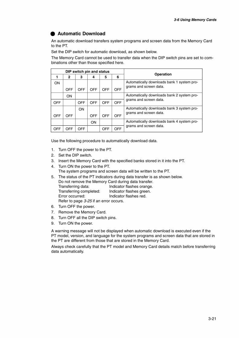
3-6 Using Memory Cards
3-21
@ Automatic DownloadAn automatic download transfers system programs and screen data from the Memory Cardto the PT.
Set the DIP switch for automatic download, as shown below.
The Memory Card cannot be used to transfer data when the DIP switch pins are set to com-binations other than those specified here.
DIP switch pin and status
1 2 3 4 5 6Operation
ON
OFF OFF OFF OFF OFF
Automatically downloads bank 1 system pro-grams and screen data.
ON
OFF OFF OFF OFF OFF
Automatically downloads bank 2 system pro-grams and screen data.
ON
OFF OFF OFF OFF OFF
Automatically downloads bank 3 system pro-grams and screen data.
ON
OFF OFF OFF OFF OFF
Automatically downloads bank 4 system pro-grams and screen data.
Use the following procedure to automatically download data.
1. Turn OFF the power to the PT.2. Set the DIP switch.3. Insert the Memory Card with the specified banks stored in it into the PT.4. Turn ON the power to the PT.
The system programs and screen data will be written to the PT.5. The status of the PT indicators during data transfer is as shown below.
Do not remove the Memory Card during data transfer.Transferring data: Indicator flashes orange.Transferring completed: Indicator flashes green.Error occurred: Indicator flashes red.Refer to page 3-25 if an error occurs.
6. Turn OFF the power.7. Remove the Memory Card.8. Turn OFF all the DIP switch pins.9. Turn ON the power.
A warning message will not be displayed when automatic download is executed even if thePT model, version, and language for the system programs and screen data that are stored inthe PT are different from those that are stored in the Memory Card.
Always check carefully that the PT model and Memory Card details match before transferringdata automatically.

3-6 Using Memory Cards
3-22
@ Automatic UploadAn automatic upload transfers system programs and screen data from the PT to the MemoryCard.
Set the DIP switch for automatic upload, as shown below.
The Memory Card cannot be used to transfer data when the DIP switch pins are set to com-binations other than those specified here.
DIP switch pin and status
1 2 3 4 5 6Operation
ON ON
OFF OFF OFF OFF
Automatically uploads system programs andscreen data to bank 1.
ON ON
OFF OFF OFF OFF
Automatically uploads system programs andscreen data to bank 2.
ON ON
OFF OFF OFF OFF
Automatically uploads system programs andscreen data to bank 3.
ON ON
OFF OFF OFF OFF
Automatically uploads system programs andscreen data to bank 4.
Use the following procedure to automatically upload data.
1. Turn OFF the power to the PT.2. Set the DIP switch.3. Insert the Memory Card into the PT.4. Turn ON the power to the PT.
The system programs and screen data will be written to the Memory Card.5. The status of the PT indicator during data transfer is as shown below.
Do not remove the Memory Card during data transfer.Transferring data: Indicator flashes orange.Transferring completed: Indicator flashes green.Error occurred: Indicator flashes red.Refer to page 3-25 if an error occurs.
6. Turn OFF the power.7. Remove the Memory Card.8. Turn OFF all the DIP switch pins.9. Turn ON the power.
A warning message will not be displayed when automatic upload is executed even if the PTmodel, version, and language for the system programs and screen data that are stored in thePT are different from those that are stored in the Memory Card
Always check carefully that the PT model and Memory Card details match before transferringdata automatically.
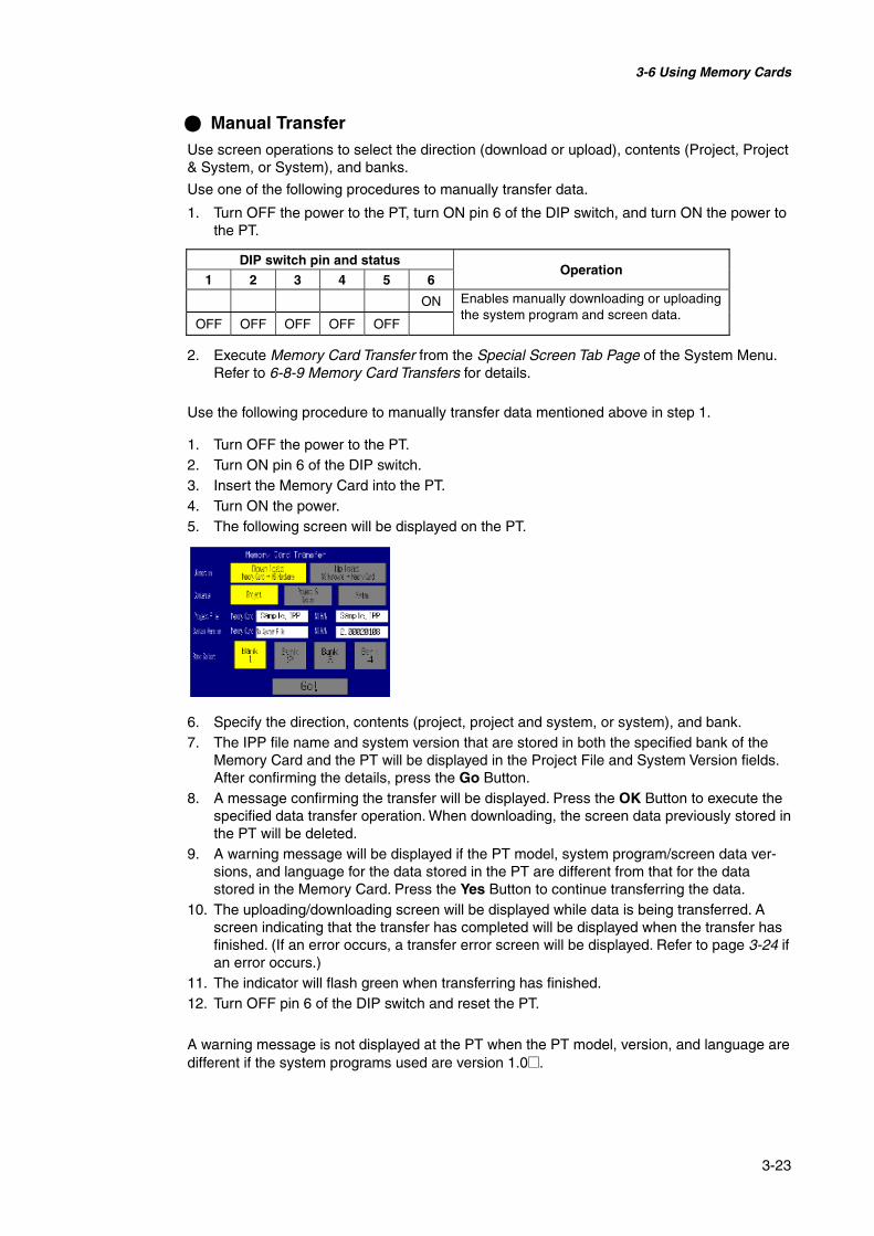
3-6 Using Memory Cards
3-23
@ Manual TransferUse screen operations to select the direction (download or upload), contents (Project, Project& System, or System), and banks.
Use one of the following procedures to manually transfer data.
1. Turn OFF the power to the PT, turn ON pin 6 of the DIP switch, and turn ON the power tothe PT.
DIP switch pin and status
1 2 3 4 5 6Operation
ON
OFF OFF OFF OFF OFF
Enables manually downloading or uploadingthe system program and screen data.
2. Execute Memory Card Transfer from the Special Screen Tab Page of the System Menu.Refer to 6-8-9 Memory Card Transfers for details.
Use the following procedure to manually transfer data mentioned above in step 1.
1. Turn OFF the power to the PT.2. Turn ON pin 6 of the DIP switch.3. Insert the Memory Card into the PT.4. Turn ON the power.5. The following screen will be displayed on the PT.
6. Specify the direction, contents (project, project and system, or system), and bank.7. The IPP file name and system version that are stored in both the specified bank of the
Memory Card and the PT will be displayed in the Project File and System Version fields.After confirming the details, press the Go Button.
8. A message confirming the transfer will be displayed. Press the OK Button to execute thespecified data transfer operation. When downloading, the screen data previously stored inthe PT will be deleted.
9. A warning message will be displayed if the PT model, system program/screen data ver-sions, and language for the data stored in the PT are different from that for the datastored in the Memory Card. Press the Yes Button to continue transferring the data.
10. The uploading/downloading screen will be displayed while data is being transferred. Ascreen indicating that the transfer has completed will be displayed when the transfer hasfinished. (If an error occurs, a transfer error screen will be displayed. Refer to page 3-24 ifan error occurs.)
11. The indicator will flash green when transferring has finished.12. Turn OFF pin 6 of the DIP switch and reset the PT.
A warning message is not displayed at the PT when the PT model, version, and language aredifferent if the system programs used are version 1.0@.

3-6 Using Memory Cards
3-24
Therefore, if the wrong data is downloaded, execute the transfer operation again using auto-matic download.
The system settings cannot be changed for the upload operation.
@ Errors• During Automatic Transfer
The indicator on the front panel will flash red if an error occurs during data transfer.Check the following items if an error occurs.• Is the Memory Card inserted into the PT?• Do the banks set with the DIP switch exist in the Memory Card?
(During Download)• Is the size of the transfer data greater than the free space in the PT or Memory Card?
Check these items before transferring data again.
Reference An error message will not be displayed if an error occurs.
• During Manual Transfer
If an error occurs during data transfer, a transfer error screen will be displayed.
Check the following items for each message displayed.
Error Messages Requiring Checking
Error message Check itemMemory Card ErrorCould not recognize a Memory Card.Check the Memory Card and reset the NSHardware.
• Is the Memory Card inserted into the PT?• Is the Memory Card damaged?
Project Transmission ErrorTransmission Failed.Check the Memory Card and reset the NSHardware.System Transmission ErrorTransmission Failed.Check the Memory Card and reset the NSHardware.
• Was the Memory Card removed during datatransfer?
• Is the free space on the Memory Card insufficient?• Is the Memory Card damaged?• Does the screen data volume exceed the memory
capacity of the PT?
Cannot find source data.Are you sure to continue Download-ing/Uploading?
• Does the transfer source directory or file exist?(Note: If the Yes Button is pressed and data istransferred, the previous data at the transfer desti-nation will be deleted.)
After checking the message, reset the PT, and transfer the data again.

3-6 Using Memory Cards
3-25
@ Inability to Replace System Program Using Automatic Download
It may not be possible to replace the system program using a normal download if the PTsystem has been damaged, e.g., if the power was turned OFF while a file was being written.Use the following procedure to operate the PT if system program replacement is not possibleor the system program is damaged and the PT does not start.
1. Copy Recover_6_x. to a Memory Card. This program can be installed with NS-DesignerVer. 6.0 by specifying it in the set up wizard.
2. Place the Memory Card into the PT and turn ON the power. The recovery program willstart automatically.Refer to the How to recover Ver. 6. pdf for details on recovery operations. This can bestarted from Windows Start – Programs – Omron – NS-Designer Ver. 6.0 – How torecover the system prog Ver. 6.
3. The system will start automatically downloading data to the PT.
The indicator will flash green when the download has finished.
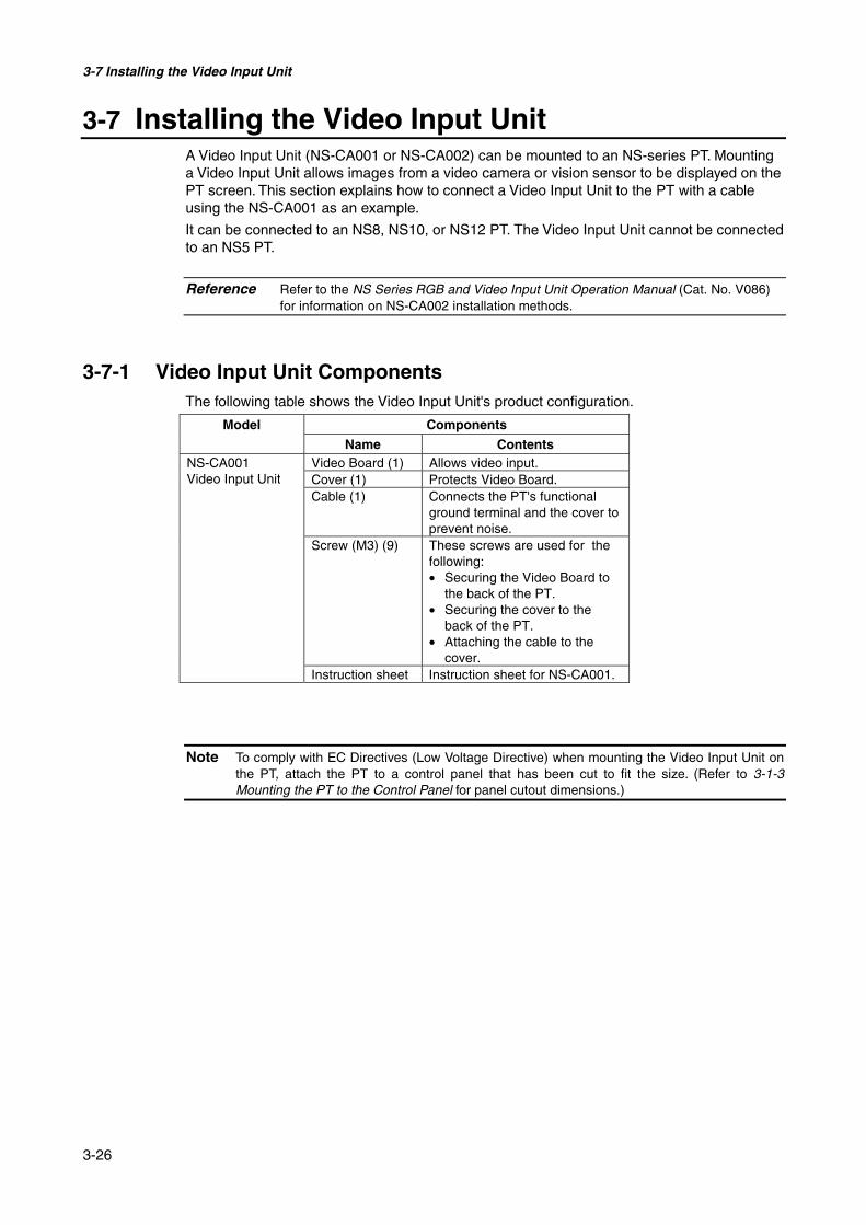
3-7 Installing the Video Input Unit
3-26
3-7 Installing the Video Input UnitA Video Input Unit (NS-CA001 or NS-CA002) can be mounted to an NS-series PT. Mountinga Video Input Unit allows images from a video camera or vision sensor to be displayed on thePT screen. This section explains how to connect a Video Input Unit to the PT with a cableusing the NS-CA001 as an example.
It can be connected to an NS8, NS10, or NS12 PT. The Video Input Unit cannot be connectedto an NS5 PT.
Reference Refer to the NS Series RGB and Video Input Unit Operation Manual (Cat. No. V086)for information on NS-CA002 installation methods.
3-7-1 Video Input Unit ComponentsThe following table shows the Video Input Unit's product configuration.
Model Components
Name ContentsVideo Board (1) Allows video input.NS-CA001
Video Input Unit Cover (1) Protects Video Board.Cable (1) Connects the PT's functional
ground terminal and the cover toprevent noise.
Screw (M3) (9) These screws are used for thefollowing:• Securing the Video Board to
the back of the PT.• Securing the cover to the
back of the PT.• Attaching the cable to the
cover.Instruction sheet Instruction sheet for NS-CA001.
Note To comply with EC Directives (Low Voltage Directive) when mounting the Video Input Unit onthe PT, attach the PT to a control panel that has been cut to fit the size. (Refer to 3-1-3Mounting the PT to the Control Panel for panel cutout dimensions.)

3-7 Installing the Video Input Unit
3-27
3-7-2 Nomenclature and FunctionsFamiliarize yourself with the nomenclature and functions of the Video Board before using theVideo Input Unit.
Video Board: Front View
Video Board: Rear View
Console Port ConnectorConnects to the console connectorof OMRON Vision Sensors andallows Vision Sensor settings to beperformed from the PT.
Positions of screws for attach-ing Video Board to PT
Contrast AdjusterUsed to adjust the contrast for videoinput. All 4 channels are adjustedtogether. They cannot be adjustedindividually.
Four Video Input ConnectorsBNC connectors for inputting NTSC/PALsignals.
Expansion Interface ConnectorConnects to the PT's expansion interface connectorwhen mounting the Video Board.

3-7 Installing the Video Input Unit
3-28
3-7-3 Installation Method for Video Input UnitThis section describes the method for mounting the Video Input Unit to the PT.
Note • Do not touch the surface of the substrate or mounted devices with your bare hands. Also,discharge static electricity from your body in advance.
• After mounting the Video Input Unit to the PT, all fittings must be tightened with the pro-vided screws. Tighten the screws to a torque of 0.6 N·m.
• Always turn OFF the power to PT before mounting or removing the Unit. Follow the proce-dures and install the Unit correctly.
• When the Video Input Unit is installed, the depth of the PT will increase by 24 mm.To install the Video Input Unit, secure sufficient space inside the control panel beforehand.
@ Installing the Video Input Unit
1. Mount the Video Board onto the back of the PT so that its expansion interface connectoris inserted into the expansion interface connector on the back of the PT and the respec-tive screw holes are aligned. Hold the Video Board by the corners keeping it parallel toback of the PT.
Push firmly on the connector end of the board to ensure that it is inserted sufficiently.
2. Secure the four corners of the Video Board with screws.
Screw holes forattaching expansionboards
Position of screws forattaching Board to PT
Align the positions of the holes.
Press here to insert the Video Board.

3-7 Installing the Video Input Unit
3-29
3. Insert screws in the screw holes for attaching the cover and tighten them slightly.
Align the cover’s screw holes with the screws and mount the cover.
Secure these four places with screws.
Mount the cover.
Insert the screws first.

3-7 Installing the Video Input Unit
3-30
Slide the cover downward and tighten the screws.
@ Connecting the CableConnect the functional ground terminal of the PT and the cover with the cable to preventmalfunction due to noise.
Connect with the cable provided.
Slide the cover
Mount the cover. Tighten the screws.

3-7 Installing the Video Input Unit
3-31
@ Removing the Video Input Unit
1. Remove the cover from the PT as follows:Loosen the screws.
Lift up on the cover and remove it.
2. Remove the screws from the four corners.
Lift up on the cover andremove it.
Remove the screws.
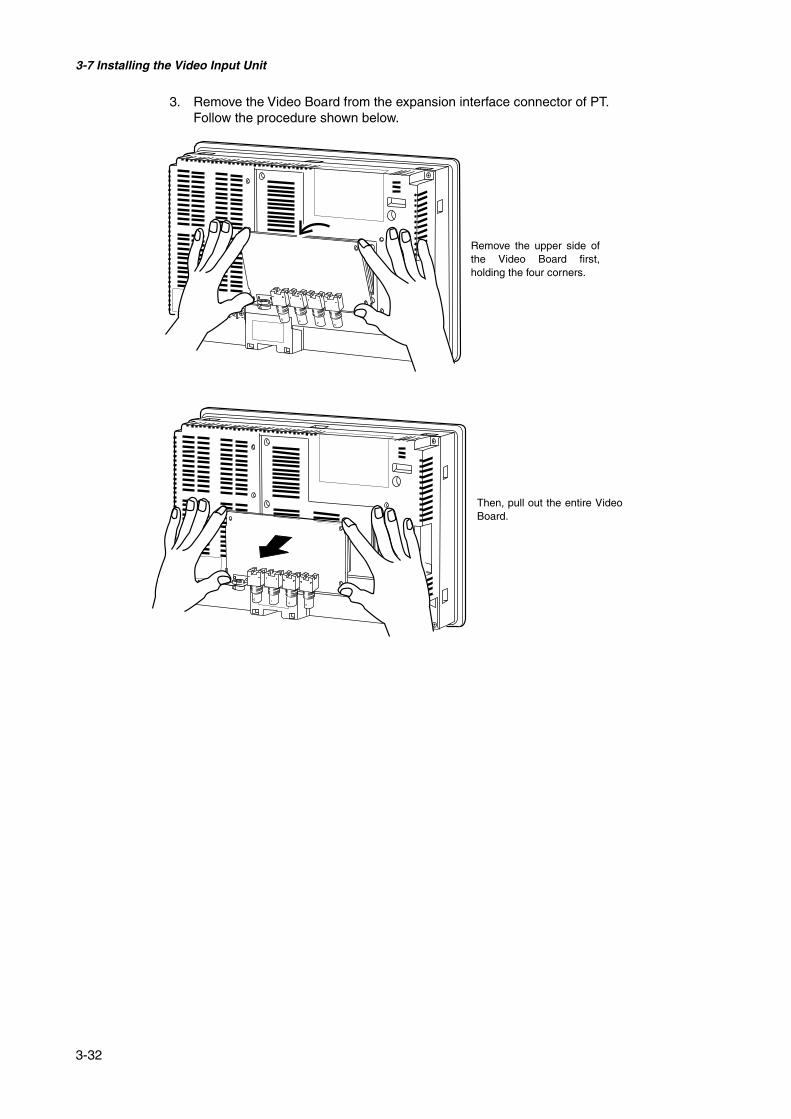
3-7 Installing the Video Input Unit
3-32
3. Remove the Video Board from the expansion interface connector of PT.Follow the procedure shown below.
Remove the upper side ofthe Video Board first,holding the four corners.
Then, pull out the entire VideoBoard.

3-7 Installing the Video Input Unit
3-33
3-7-4 Connecting to Video Input ConnectorsUse the following method to connect cameras to the Video Input Unit mounted to the PT.
Note The tensile load of the cable is 30 N maximum. Do not exceed maximum load.
@ Connecting to Video Input Connectors1. Insert the BNC socket on the camera’s video output cable into a video input connector.
2. After inserting the BNC socket, twist it clockwise until it locks into place
Twist clockwise.
Protuberance
BNC socket
Video input connectors Insert the BNC socket so thatthe groove is aligned with theprotuberance.

3-7 Installing the Video Input Unit
3-34
@ Removing the Video Input Connector1. Unlock the BNC socket on the camera’s video output cable by twisting it counterclock-
wise while pushing it.
2. After unlocking the BNC socket, pull it out.
Push
Twist counterclockwise
Pull out

3-7 Installing the Video Input Unit
3-35
If the camera’s video output cable uses an RCA plug, connect it to the video inputconnector using a BNC-RCA connector in the way shown below.
Note A BNC-RCA connector is provided with the Monitor Cable (F150-VM) for OMRON Vision Sen-sors. It is not provided with the Video Input Unit (NS-CA001).
Video input connector(BNC type)
BNC-RCA connector (See note.)
RCA plug

3-7 Installing the Video Input Unit
3-36
@ Connecting to the Console Port ConnectorUse the following method to connect the Video Board’s console port connector to the consoleconnector of an OMRON Vision Sensor (F150-C10V3, F160-C10, F180-C10, F400-C10V2,F250-C10, V530-R150V2).
1. Insert the socket of the Relay Cable (F150-VKP; see note) into the Video Board’s consoleport connector.
Note The Relay Cable (F150-VKP) is the cable used to connect the Video Board’s console con-nector to the console connector of an OMRON Vision Sensor.
@ Removing the Console Port ConnectorUse the following method to remove the Relay Cable from the Video Board’s console portconnector.
1. Remove the Relay Cable by pulling on the connector as shown below.
Console port connector
Pull here to unlock thecable and remove it.
Relay cable
Align with groove andinsert.
Relay cable
The socket locks into placewhen it is inserted.
Video Board's consoleport connector

3-7 Installing the Video Input Unit
3-37
@ Setting the ContrastIf the picture displayed on the PT screen is too bright or dark, contrast adjustment is required.Contrast adjustment is usually performed using one of the following procedures.
• Select Video Configuration from the Special Screen Tab Page in the System Menu. (Referto Video Configuration under 2-18 Special Functions in the NS-series Programmable Ter-minals Programming Manual.)
• Select the Contrast Adjustment function for Command Buttons. (Refer to Command Buttonsunder 2-9 Buttons in the NS-series Programmable Terminals Programming Manual).
If the contrast is not improved using the above methods, change the contrast with the VideoBoard’s contrast adjustor using the following method.
Turn the contrast adjustor gradually using a small screwdriver while checking the picture dis-played on the PT screen.
If turning the contrast adjustor too much, the image may be distorted. Turn the contrast ad-justor in the opposite direction to remove the noise.
Contrast Adjustor
Grooves between blackdots indicate the settings.
HighLow
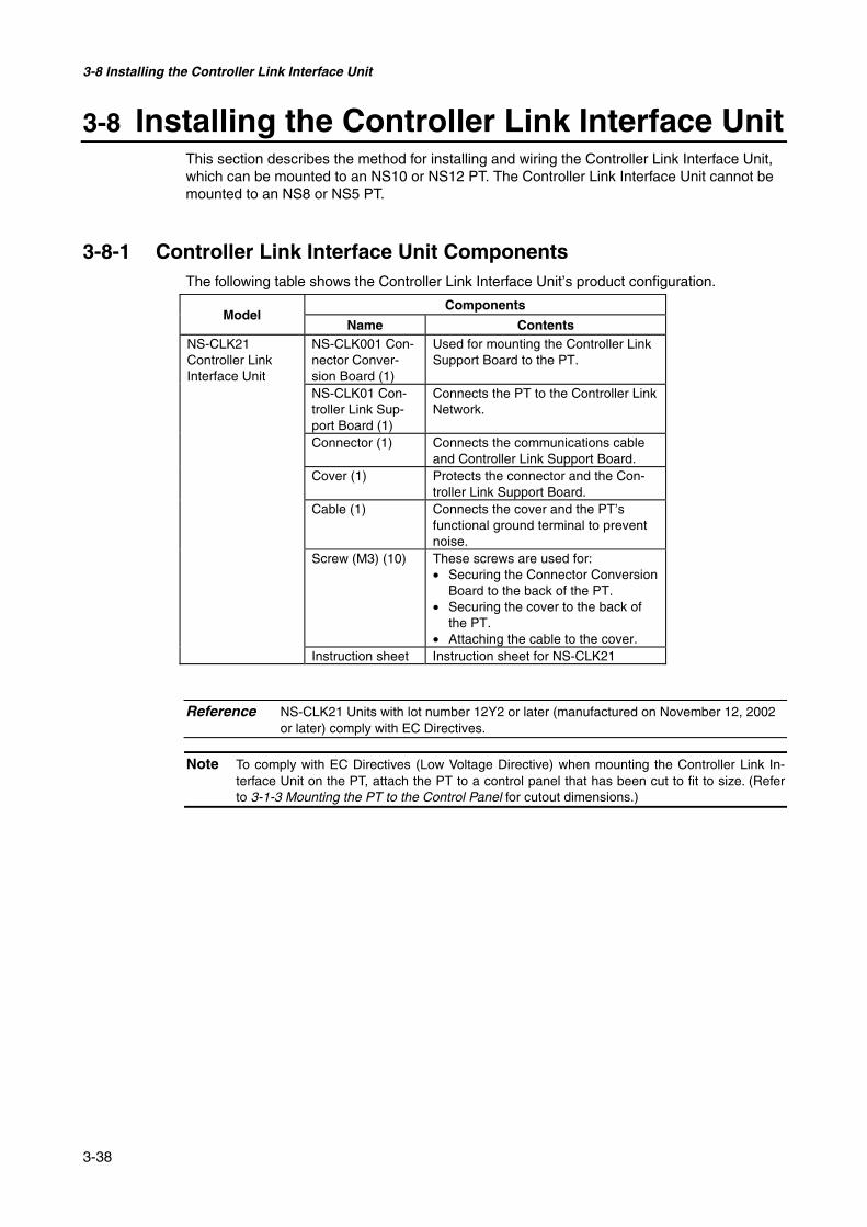
3-8 Installing the Controller Link Interface Unit
3-38
3-8 Installing the Controller Link Interface UnitThis section describes the method for installing and wiring the Controller Link Interface Unit,which can be mounted to an NS10 or NS12 PT. The Controller Link Interface Unit cannot bemounted to an NS8 or NS5 PT.
3-8-1 Controller Link Interface Unit ComponentsThe following table shows the Controller Link Interface Unit’s product configuration.
ComponentsModel
Name ContentsNS-CLK21Controller LinkInterface Unit
NS-CLK001 Con-nector Conver-sion Board (1)
Used for mounting the Controller LinkSupport Board to the PT.
NS-CLK01 Con-troller Link Sup-port Board (1)
Connects the PT to the Controller LinkNetwork.
Connector (1) Connects the communications cableand Controller Link Support Board.
Cover (1) Protects the connector and the Con-troller Link Support Board.
Cable (1) Connects the cover and the PT’sfunctional ground terminal to preventnoise.
Screw (M3) (10) These screws are used for:• Securing the Connector Conversion
Board to the back of the PT.• Securing the cover to the back of
the PT.• Attaching the cable to the cover.
Instruction sheet Instruction sheet for NS-CLK21
Reference NS-CLK21 Units with lot number 12Y2 or later (manufactured on November 12, 2002or later) comply with EC Directives.
Note To comply with EC Directives (Low Voltage Directive) when mounting the Controller Link In-terface Unit on the PT, attach the PT to a control panel that has been cut to fit to size. (Referto 3-1-3 Mounting the PT to the Control Panel for cutout dimensions.)
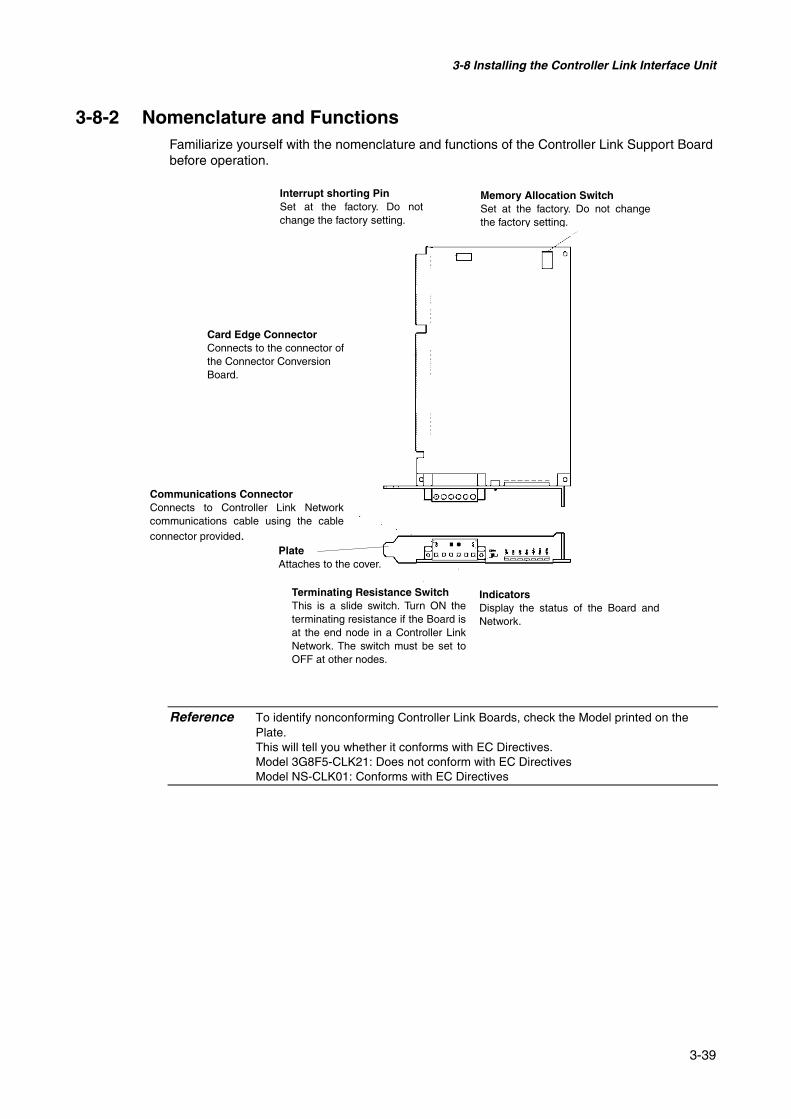
3-8 Installing the Controller Link Interface Unit
3-39
3-8-2 Nomenclature and FunctionsFamiliarize yourself with the nomenclature and functions of the Controller Link Support Boardbefore operation.
Reference To identify nonconforming Controller Link Boards, check the Model printed on thePlate.This will tell you whether it conforms with EC Directives.Model 3G8F5-CLK21: Does not conform with EC DirectivesModel NS-CLK01: Conforms with EC Directives
Card Edge ConnectorConnects to the connector ofthe Connector ConversionBoard.
Memory Allocation SwitchSet at the factory. Do not changethe factory setting.
Communications ConnectorConnects to Controller Link Networkcommunications cable using the cableconnector provided.
Interrupt shorting PinSet at the factory. Do notchange the factory setting.
Terminating Resistance SwitchThis is a slide switch. Turn ON theterminating resistance if the Board isat the end node in a Controller LinkNetwork. The switch must be set toOFF at other nodes.
IndicatorsDisplay the status of the Board andNetwork.
PlateAttaches to the cover.

3-8 Installing the Controller Link Interface Unit
3-40
@ Indicators
Indicator Name Color status MeaningRUN Operating Green Lit Normal operation.
Not lit A Board operating error (watchdog timer error) oc-curred.
ERC Communica-tions error
Red Lit One of the following errors occurred.• Communications error• Same node address used twice (i.e., address dupli-
cation error)• Hardware error
Not lit Normal operationERH EEPROM error Red Lit One of the following errors occurred.
• EEPROM error• EEPROM data link table error• EEPROM routing table error• EEPROM network parameter error
Not lit No EEPROM error.INS Network par-
ticipationYellow Lit The Board is participating in the network.
Not lit The Board is not participating in the network.SD Send Yellow Lit Sending data.
Not lit Not sending data.RD Receive Yellow Lit Receiving data.
Not lit Not receiving data.LNK Data link Yellow Lit Participating in data link.
Flash-ing
Error in data link table setting.
Not lit Not participating in data link or data link inactive.

3-8 Installing the Controller Link Interface Unit
3-41
@ Switch SettingsThe following settings are made at the factory. Do not change these settings.
Item Switch SettingMemory address Memory allocation switch SW1: ON
SW2: ONSW3: OFFSW4: ON
Interrupt level Interrupt shorting pin Set to IRQ10.
@ Setting Terminating ResistanceTurn the built-in terminating resistance ON or OFF using the terminating resistance switch(slide switch). Terminating resistance is required at the both ends of a wired network to ab-sorb unnecessary signals and reduce the noise. The Controller Link Support Board has built-in terminating resistance, which can be connected simply by setting the slide switch to ON.
Set the switch to ON to connect the terminating resistance at both end nodes in wired net-works and set the switch to OFF at all other nodes.
Setting Terminating resistanceOFF (factory setting) Not connectedON Connected
Note This switch can be set after the Controller Link Interface Unit is installed on the PT.Turn OFF the power of the PT before changing the setting.
Reference This switch is set to OFF by default (terminating resistance disconnected).
ON

3-8 Installing the Controller Link Interface Unit
3-42
3-8-3 Installation Method for Controller Link Interface UnitThis section explains the method for mounting a Controller Link Interface Unit to the PT.
The Controller Link Interface Unit can be mounted to NS12 and NS10 PTs only. It cannot bemounted to an NS8 or NS5 PT.
Note • Do not touch the surface of the substrate or mounted devices with your bare hands. Also,discharge static electricity from your body in advance.
• After mounting the Controller Link Interface Unit to the PT, all fittings must be tightenedwith the provided screws. Tighten the screws to a torque of 0.6 N⋅m.
• Always turn OFF the power to PT before mounting or removing the Unit. Follow the proce-dures and install the Unit correctly.
• When the Controller Link Interface Unit is installed, the depth of the PT will increase by35 mm.
• To install the Controller Link Interface Unit, secure sufficient space inside the control panelbeforehand.

3-8 Installing the Controller Link Interface Unit
3-43
@ Connecting and Disconnecting
1. Mount the Connector Conversion Board onto the back of the PT so that its expansion in-terface connector is inserted into the expansion interface connector on the back of the PTand the respective screw holes are aligned. Hold the Board by the corners keeping it par-allel to back of the PT.
2. Secure the four corners of the Connector Conversion Board with screws.
PT’s expansion in-terface connector
Connector ConversionBoard Connector Conversion Board’s
expansion interface connector
Secure these four places with screws.
Hold the four corners and insert straightto the expansion interface connector onthe PT
Align the positions of the holes

3-8 Installing the Controller Link Interface Unit
3-44
3. Insert the Controller Link Support Board’s card edge connector into the Connector Con-version Board’s connector.
Reference Follow the steps given below if it is hard to insert the card edge connector to the con-nector on the connector conversion board.
ConnectorCard edge connector
Connector Conversion Board Controller Link Support Board

3-8 Installing the Controller Link Interface Unit
3-45
4. Mount the cover to the PT.
5. Secure the five places shown below with screws.
Secure these five placeswith screws.
Controller LinkSupport Board
Cover
Cover
Controller LinkSupport Board
(Underside view)

3-8 Installing the Controller Link Interface Unit
3-46
• Connecting the CableConnect the functional ground terminal of the PT and the cover with the cable to preventmalfunction due to noise.
• Removing Controller Link Interface Unit
1. Remove the cover.
Remove these screws andremove the cover.
Cover
Controller LinkSupport Board
Connect with the cable provided.

3-8 Installing the Controller Link Interface Unit
3-47
2. Disconnect the Controller Link Support Board from the connector conversion board. Holdboth ends of the Controller Link Support Board and pull out straight.
3. Remove the screws from the Connector Conversion Board.
Hold both ends of theController Link SupportBoard and pull out straight.
Remove the four screws.

3-8 Installing the Controller Link Interface Unit
3-48
4. Disconnect the Connector Conversion Board from the PT. To do this, follow the stepsgiven below.
Hold the four corners of theBoard and detach upper sidefirst.
Then, pull out the Boardcompletely.

3-8 Installing the Controller Link Interface Unit
3-49
3-8-4 WiringThis section describes the method for wiring the network communications cable to the Con-troller Link Support Board.
@ Wiring the Communications CableWire the communications cable to connect identical signals.
Note • Use the cable specified for the communications cable.• Keep communications cables separated from power lines or high-tension lines to prevent
influences from electronic noise.• Ground the shield of the communications cable at one end of the network. Do not ground
the shield at both ends.• Do not connect the shield cable of the communications cable to a ground that is also being
used for power-system devices, such as inverters.• Do not run wiring outdoors. If outdoor wiring is necessary, take protective measures against
lightening, such as underground wiring or wiring inside pipes.• Always turn OFF the power to PT before connecting the communications cable or install-
ing/removing the connector.• Use the connector attached to the Controller Link Support Board.
Connecting the Communications Cable
Connect the communications cable to the Controller Link Support Board after first connectingit to the cable connector provided.
Use one of the twisted-pair cables listed below as the communications cable.
Model Manufacturer RemarksLi2Y-FCY2x0.56qmm KROMBERG & SHUBERT, De-
partment KOMTECGerman company
1x2xAWG-20PE+Tr.CUSN+PVC
DRAKA CABLES INDUSTRIAL Spanish company
#9207 BELDEN American companyESVC0.5x2C Bando Densen Co. Japanese company
Note • Use the cables listed above.• Normal communications may not be possible if a communications cable other than those
listed above is used.
Reference • Terminals for the same signal on the Controller Link Support Board’s connector areconnected internally.
• The thickness of the ground wire connected to the Controller Link Support Board’sconnector must be less than 2.5 mm2.
• Connect to the network using the special connector provided with the Controller LinkInterface Unit.

3-8 Installing the Controller Link Interface Unit
3-50
Note • The minimum length of the communications cable between nodes is 1 m. Prepare thecommunications cables at a length of 1 m or longer.
• Use the multidrop method for connecting nodes. Normal communications will not be possi-ble with T branches.
Ground all of the shield lines (including the shield line for the node at only one end of thenetwork) in the way shown below.
Reference • Terminals of the same type are connected internally. They can thus be connected toeither the right or left half of the end Boards.
@ Connecting Cables to Communications ConnectorsWhen connecting a communications cable to a Controller Link Support Board, connect thecable to the attached connector first and then attach to the connector to the Board.
Connect the communications cable to the connector using the following procedure.
1. Taking care not to damage the mesh of the shield, strip about 50 mm off the end of thecable. Do not strip the cable too far because it may cause a short-circuit.
End Board
Board in the middleof the network
Board at the end ofthe network
Terminatingresistance: ON
Terminatingresistance: OFF
Terminatingresistance: ON
Board at the end ofthe network
Ground
Approx. 50 mm

3-8 Installing the Controller Link Interface Unit
3-51
2. At the end connected to the node, twist the mesh of the shield into a single wire. Leavesufficient length at the tip of the twisted shield to be connected to a crimp terminal andcover the remaining section with heat-shrink tubing. Cut all the shield mesh off at the endnot connected to the node.
3. Strip the ends of the signal wires far enough to attach to the crimp terminals. Twist thewire strands together.
4. Cover the end of the cable at the point it was stripped to in step 1 with vinyl tape or heat-shrink tubing.
5. Attach crimp terminals to the shield wire and signal wires. Cover the connections with vi-nyl tape or heat-shrink tubing.
Reference • We recommend the Phoenix AI-series crimp terminals shown in the following diagram.
Phoenix’s ZA3 crimping tool can be used to attach these terminals.
Cover with vinyl tapeor heat- shrink tubing.
Crimp terminal Wire
Insert the wire and crimp the terminal to the wire.
Wire created bytwisting the shieldmesh.
Cover with heat-shrink tubing
Leave enough exposed wire toattach to a crimp terminal.
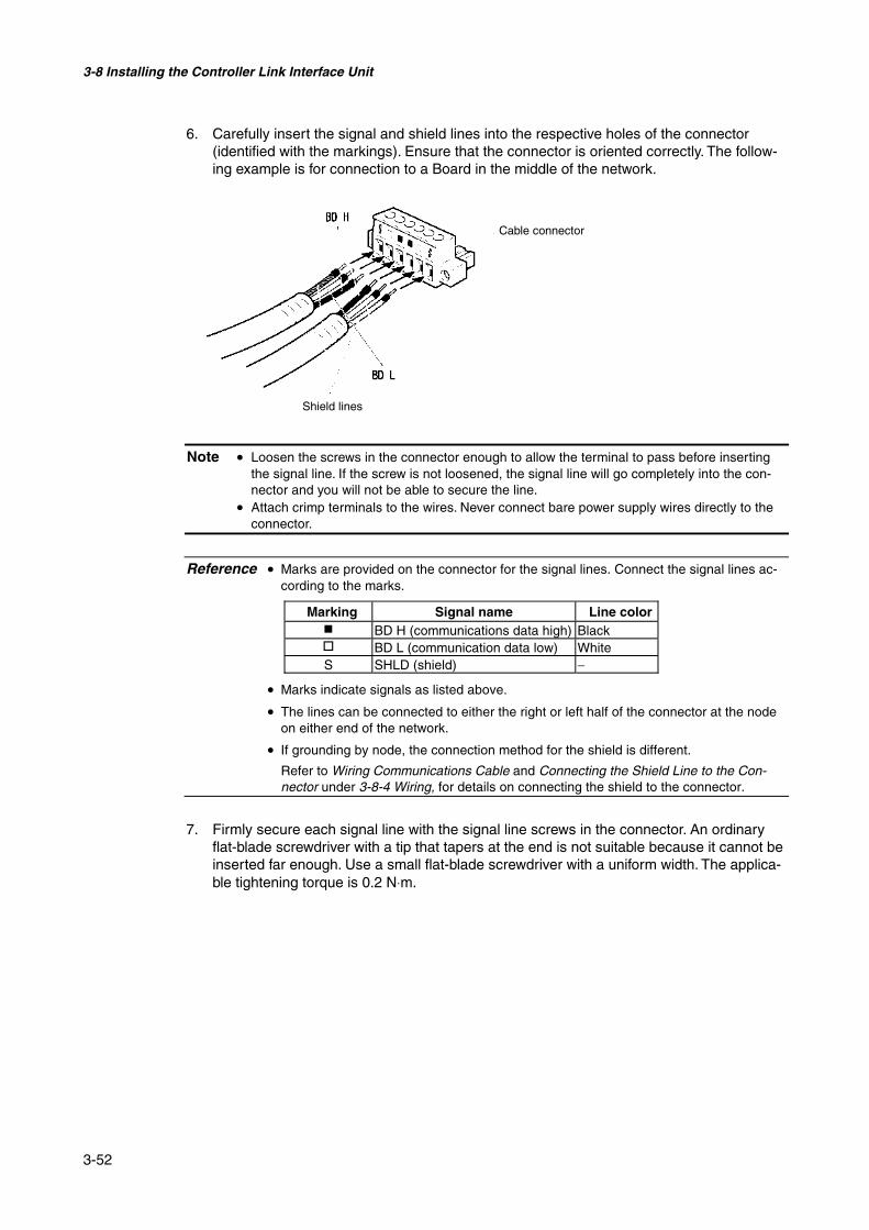
3-8 Installing the Controller Link Interface Unit
3-52
6. Carefully insert the signal and shield lines into the respective holes of the connector(identified with the markings). Ensure that the connector is oriented correctly. The follow-ing example is for connection to a Board in the middle of the network.
Note • Loosen the screws in the connector enough to allow the terminal to pass before insertingthe signal line. If the screw is not loosened, the signal line will go completely into the con-nector and you will not be able to secure the line.
• Attach crimp terminals to the wires. Never connect bare power supply wires directly to theconnector.
Reference • Marks are provided on the connector for the signal lines. Connect the signal lines ac-cording to the marks.
• Marks indicate signals as listed above.
• The lines can be connected to either the right or left half of the connector at the nodeon either end of the network.
• If grounding by node, the connection method for the shield is different.
Refer to Wiring Communications Cable and Connecting the Shield Line to the Con-nector under 3-8-4 Wiring, for details on connecting the shield to the connector.
7. Firmly secure each signal line with the signal line screws in the connector. An ordinaryflat-blade screwdriver with a tip that tapers at the end is not suitable because it cannot beinserted far enough. Use a small flat-blade screwdriver with a uniform width. The applica-ble tightening torque is 0.2 N⋅m.
Marking Signal name Line color BD H (communications data high) Black BD L (communication data low) WhiteS SHLD (shield) −
Cable connector
Shield lines

3-8 Installing the Controller Link Interface Unit
3-53
Reference The following screwdriver is available from OMRON.Model XW4Z-00C
@ Connecting the Connector to the BoardConnect the connector on the communications cable to the connector on the Board using thefollowing procedure.
1. Insert the connector on the communications cable into the connector on the Board asshown below.
2. Secure the connector to the Board by tightening the screws on the connector. The appli-cable tightening torque is 0.2 N⋅m.
Controller LinkSupport Board
Cable connector
Small flat-bladescrewdriver with auniform width
0.6 mm
Side Front
3.5 mm

3-8 Installing the Controller Link Interface Unit
3-54
Note • If the connector becomes disconnected, not only will the Board be unable to perform com-munications with other nodes in the network, the network will be split into two at the point ofdisconnection. Take the utmost care to ensure that the connector does not become discon-nected during communications.
• Do not pull on the communications cable.• When bending the communications cable, allow 60 mm or more for the bending radius (R).
• Do not place heavy objects on the communications cable.• Supply power only after checking the wiring thoroughly.• Always tighten the screws of connector after connecting the communications cable.
Controller Link Support Board
Communications disabled
Connector
Network split(communications disabled)

Section 4
Connecting the Host to Serial Port
This section describes the methods for connecting the host to the serial port of the PT.
4-1 1:1 Host Connection ....................................................................................................... 4-24-1-1 Connection Methods................................................................................................. 4-24-1-2 Unit Setting Methods................................................................................................ 4-4
4-2 1:N Host Connection....................................................................................................... 4-74-2-1 Connection Methods................................................................................................. 4-74-2-2 Unit Setting Methods................................................................................................ 4-7
4-3 High-speed 1:N NT Link .............................................................................................. 4-154-3-1 Unit Setting Methods.............................................................................................. 4-16
4-4 Recommended Connector Cables ................................................................................. 4-23

4-1 1:1 Host Connection
4-2
4-1 1:1 Host Connection
4-1-1 Connection Methods
This section describes the methods for connecting the host to serial port A or B of the PTusing RS-232C or RS-422A communications. The connection methods are as follows:
• Direct Connection using RS-232C (Refer to page 3 of this section.)This is the easiest connection method. OMRON cables with connectors can be used, de-pending on the host being connected.
RS-232C cable(15 m max.)
HostPT
• A 1:1 Connection using RS-422A and an NS-AL002 RS-232C/RS-422A Converter (Referto page 3 of this section.)This connection method allows an extended communications distance of up to 500 m.
RS-422A cable(500 m max.)
NS-AL002Adapter
PT Host
The NS-series PTs have two serial ports that can be used simultaneously. Therefore, twohosts can be connected at the same time. Any combination of devices can be connected tothe PT.
RS-232C cable orRS-232C/RS-422A Converter+ RS-422A cable
PT Host 1
Host 2
Serial port A
Serial port B
(See note.)
(See note.)
Note: Each port allows 1:N connection. The NS-AL002 Converter can be connected to one serial portonly.
Note • Always tighten the connector screws after connecting communications cables.• The connector’s pull load is 30 N.
Do not subject the connectors to a greater load than that specified.
• Supported RS-232C Host UnitsSome models and series of OMRON PLCs have a built-in 1:1 NT Link function. Some PLCscan also be connected in a 1:1 NT Link by adding a Serial Communications Board or Com-munications Board.
When connecting the PT to a PLC, check the series and model of the PLC and the model ofthe Board mounted to the PLC.
Refer to Appendix 7 Standard Models for details on the Units that can be connected to NS-series PTs as hosts using RS-232C or RS-422A communications in a 1:1 NT Link.
Reference CS/CJ series CPU Units cannot be connected in a 1:1 NT Link. Use a 1:1 connectionthrough 1:N NT Links (normal or high speed). For details, refer to 1:N NT Links or High-speed 1:N NT Links in Section 4-2 1:1 Host Connection.
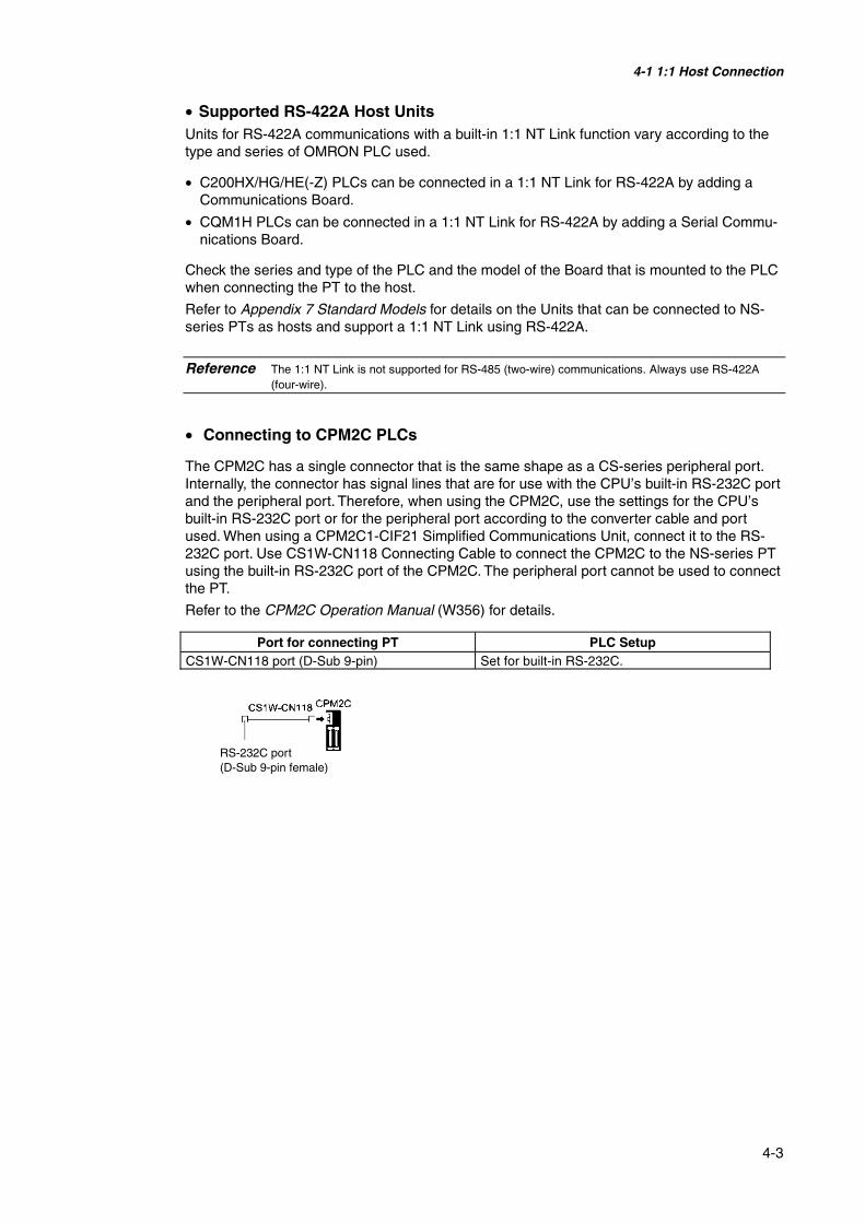
4-1 1:1 Host Connection
4-3
• Supported RS-422A Host UnitsUnits for RS-422A communications with a built-in 1:1 NT Link function vary according to thetype and series of OMRON PLC used.
• C200HX/HG/HE(-Z) PLCs can be connected in a 1:1 NT Link for RS-422A by adding aCommunications Board.
• CQM1H PLCs can be connected in a 1:1 NT Link for RS-422A by adding a Serial Commu-nications Board.
Check the series and type of the PLC and the model of the Board that is mounted to the PLCwhen connecting the PT to the host.
Refer to Appendix 7 Standard Models for details on the Units that can be connected to NS-series PTs as hosts and support a 1:1 NT Link using RS-422A.
Reference The 1:1 NT Link is not supported for RS-485 (two-wire) communications. Always use RS-422A(four-wire).
• Connecting to CPM2C PLCs
The CPM2C has a single connector that is the same shape as a CS-series peripheral port.Internally, the connector has signal lines that are for use with the CPU’s built-in RS-232C portand the peripheral port. Therefore, when using the CPM2C, use the settings for the CPU’sbuilt-in RS-232C port or for the peripheral port according to the converter cable and portused. When using a CPM2C1-CIF21 Simplified Communications Unit, connect it to the RS-232C port. Use CS1W-CN118 Connecting Cable to connect the CPM2C to the NS-series PTusing the built-in RS-232C port of the CPM2C. The peripheral port cannot be used to connectthe PT.
Refer to the CPM2C Operation Manual (W356) for details.
Port for connecting PT PLC SetupCS1W-CN118 port (D-Sub 9-pin) Set for built-in RS-232C.
RS-232C port(D-Sub 9-pin female)
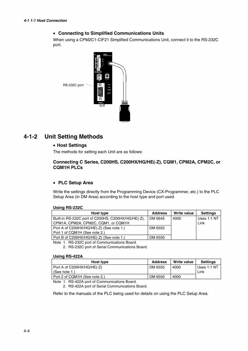
4-1 1:1 Host Connection
4-4
• Connecting to Simplified Communications UnitsWhen using a CPM2C1-CIF21 Simplified Communications Unit, connect it to the RS-232Cport.
4-1-2 Unit Setting Methods• Host SettingsThe methods for setting each Unit are as follows:
Connecting C Series, C200HS, C200HX/HG/HE(-Z), CQM1, CPM2A, CPM2C, orCQM1H PLCs
• PLC Setup Area
Write the settings directly from the Programming Device (CX-Programmer, etc.) to the PLCSetup Area (in DM Area) according to the host type and port used.
Using RS-232CHost type Address Write value Settings
Built-in RS-232C port of C200HS, C200HX/HG/HE(-Z),CPM1A, CPM2A, CPM2C, CQM1, or CQM1H
DM 6645
Port A of C200HX/HG/HE(-Z) (See note 1.)Port 1 of CQM1H (See note 2.)
DM 6555
Port B of C200HX/HG/HE(-Z) (See note 1.) DM 6550
4000 Uses 1:1 NTLink
Note 1. RS-232C port of Communications Board.2. RS-232C port of Serial Communications Board.
Using RS-422AHost type Address Write value Settings
Port A of C200HX/HG/HE(-Z)(See note 1.)
DM 6555 4000
Port 2 of CQM1H (See note 2.) DM 6550 4000
Uses 1:1 NTLink
Note 1. RS-422A port of Communications Board.2. RS-422A port of Serial Communications Board.
Refer to the manuals of the PLC being used for details on using the PLC Setup Area.
RS-232C port

4-1 1:1 Host Connection
4-5
• Setting the Front Panel DIP Switch
Using RS-232CWhen using C200HX/HG/HE(-Z), CQM1, or CQM1H PLCs, set the DIP switch on the frontpanel to enable the PLC Setup Area (Data Memory) settings, as follows:
• Setting the CPM2A Front Panel DIP SwitchWhen using a CPM2A, set the DIP switch on the front panel to enable the PLC Setup Area(Data Memory) settings, as follows:
• Setting the CPM2C Front Panel DIP SwitchesWhen using a CPM2C, set the switches on the front panel to enable the PLC Setup Area(Data Memory) settings, as follows:
C200HX/HG/HE(-Z) CQM1
RS-232C Communications Conditions SettingSet pin 5 of the DIP switch to OFF to enable thePLC Setup Area settings.
CQM1H
Set the communicationsconditions setting switch toOFF (lower position).
Set the switches according to whether the peripheral port orthe built-in RS-232C port is used, as follows:• Connecting the PT to the built-in RS-232C port
(The peripheral port is used to connect devices that re-quire non-standard communications settings.)
SW1: OFFSW2: ON
SW1: OFFSW2: OFF
• Connecting the PT to the built-in RS-232C port(The peripheral port is used to connect the ProgrammingConsole.)

4-1 1:1 Host Connection
4-6
• Setting the Communications Board Switches (Using RS-422A)Set the switches of the C200HX/HG/HE(-Z) Communications Board as follows:
Switch 1: 4 (Four-wire method = RS-422A)
Switch 2: ON (terminator ON = terminating resistance used)
Set the switches of the CQM1H Serial Communications Board as follows:
Two-wire/four-wire switch (WIRE): 4 (Four-wire method = RS-422A)
Terminating resistance switch (TERM): ON (terminator ON = terminating resistance used)
• Connecting to CVM1/CV Series (-V@) PLCs (Using RS-232C/RS-422A)
PLC SetupWhen using CVM1/CV-series PLCs, always set the Execute Process (Execute Control 2) inthe PLC Setup to synchronous execution.
Setting the Front Panel DIP SwitchSet the DIP switch on the front panel, as shown in the following diagram.
Switch settingSwitches between RS-232C and RS-422A
Communications setting (DIP switch pin 3)Set pin 3 to ON (NT Link communications used).
Terminating resistance setting (DIP switch pin 6, forRS-422A only)Set pin 6 to ON (terminating resistance used).
Communications pathswitch(RS-232C-to-RS-422A)
Serial Communications Board (Inner Board slot 1)
Terminating resistance switchSet to ON (right position)
Two-wire/four-wire switchSet to 4 (right position)

4-2 1:N Host Connection
4-7
4-2 1:N Host Connection
4-2-1 Connection MethodsThis section describes the methods used to connect multiple PTs to a single host in a 1:Nconnection and provides information on the relationship between the connection methods andthe communications methods.
• The Host and PTs are connected in a 1:N configuration using RS-422A with an RS-232C/RS-422A Converter. (Refer to page 4-9.)
This connection method can be used for 1:N NT Link connections (normal, high-speed).
Note: It is not possible to connect to a PLC via NT Link (1:N) with both serial ports A and B at thesame time.
• Supported Host UnitsThe OMRON PLCs that can be connected in 1:N NT Links are limited to the CS-series, CJ-series, and C-series PLCs. CS-series PLCs can also be connected in 1:N NT Links by usinga CS1W-SCU21 Serial Communications Unit. CJ-series PLCs can also be connected in 1:NNT Links by using a CJ1W-SCU41 Serial Communications Unit.
Check the series and model of the PLC and the model of the Board or Unit that is mounted tothe PLC when connecting the PTs to the host.
For details on the Units used as hosts that can be connected in 1:N NT Links, refer to Ap-pendix 7 Standard Models.
Reference RS-485 (two-wire) communications are not supported by the NS Series. Always use RS-422A (four-wire).
Reference CS-series PLCs with -V1 suffix support high-speed 1:N NT Links as well as normal 1:N NT Links.CS-series PLCs without the -V1 suffix can also be connected to high-speed 1:N NT Links if the lat-est Serial Communications Board/Unit is used. Refer to High-speed 1:N NT Link for details. (page4-15)
4-2-2 Unit Setting Methods
Host Settings
The methods for setting each Unit are as follows:
Connecting C-series C200HX/HG/HE(-Z), and CQM1H PLCs
HostPTNS-AL002Converter
RS-422A cable
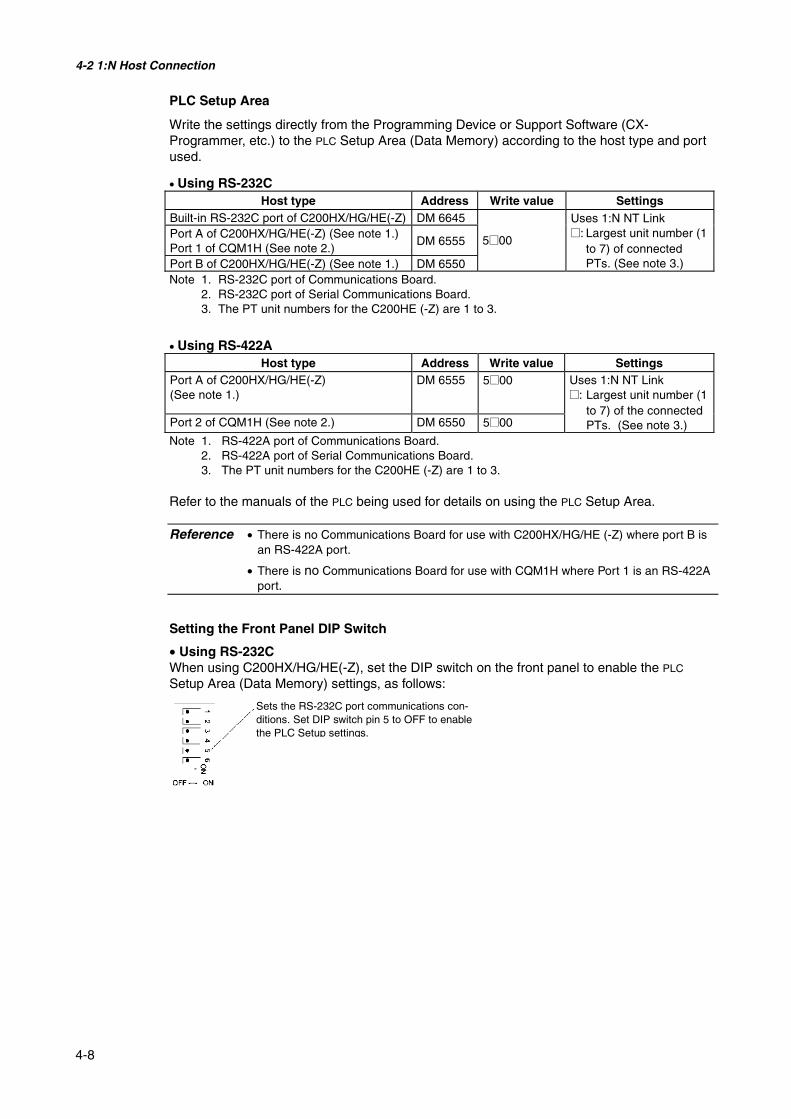
4-2 1:N Host Connection
4-8
PLC Setup Area
Write the settings directly from the Programming Device or Support Software (CX-Programmer, etc.) to the PLC Setup Area (Data Memory) according to the host type and portused.
• Using RS-232CHost type Address Write value Settings
Built-in RS-232C port of C200HX/HG/HE(-Z) DM 6645Port A of C200HX/HG/HE(-Z) (See note 1.)Port 1 of CQM1H (See note 2.)
DM 6555
Port B of C200HX/HG/HE(-Z) (See note 1.) DM 6550
5@00
Uses 1:N NT Link@: Largest unit number (1
to 7) of connectedPTs. (See note 3.)
Note 1. RS-232C port of Communications Board.2. RS-232C port of Serial Communications Board.3. The PT unit numbers for the C200HE (-Z) are 1 to 3.
• Using RS-422AHost type Address Write value Settings
Port A of C200HX/HG/HE(-Z)(See note 1.)
DM 6555 5@00
Port 2 of CQM1H (See note 2.) DM 6550 5@00
Uses 1:N NT Link@: Largest unit number (1
to 7) of the connectedPTs. (See note 3.)
Note 1. RS-422A port of Communications Board.2. RS-422A port of Serial Communications Board.3. The PT unit numbers for the C200HE (-Z) are 1 to 3.
Refer to the manuals of the PLC being used for details on using the PLC Setup Area.
Reference • There is no Communications Board for use with C200HX/HG/HE (-Z) where port B isan RS-422A port.
• There is no Communications Board for use with CQM1H where Port 1 is an RS-422Aport.
Setting the Front Panel DIP Switch
• Using RS-232CWhen using C200HX/HG/HE(-Z), set the DIP switch on the front panel to enable the PLC
Setup Area (Data Memory) settings, as follows:
Sets the RS-232C port communications con-ditions. Set DIP switch pin 5 to OFF to enablethe PLC Setup settings.

4-2 1:N Host Connection
4-9
Setting the Communications Board Switches
• Using RS-422ASet the switches of the C200HX/HG/HE(-Z) Communications Board, as follows:
Switch 1: 4 (Four-wire method = RS-422A)
Switch 2: ON (terminator ON = terminating resistance used)
Set the switches of the CQM1H Serial Communications Board as follows:
Two-wire/four-wire switch (WIRE): 4 (Four-wire method = RS-422A)
Terminating resistance switch (TERM): ON (terminator ON = terminating resistance used)
Connecting to CS-series CPU Units
CS-series CPU Units:
CS1G/H-CPU@@-E(V1) and CS1G/H-CPU@@H
PLC Setup Area
• Using RS-232CWhen connecting the PT to a CS-series CPU Unit, set the communications conditions in thePLC Setup according to the communications port used, as follows:
Using Built-in RS-232C Port of CS1G/H or CS1G/H-H
Address Write value Settings160 8200 1:N NT Link Mode161 0000 to 0009 (See note 1.) Baud rate (normal)166 000@ @: Largest unit number (1 to 7) of the connected
PTs. (See note 2.)Note 1. Set the baud rate to a numeric value between 0000 to 0009 Hex. (The setting is the same for
any value between 0000 and 0009 Hex.)2. When using a 1:N connection, set the value for @ to 1 or higher.
For example, to connect PTs with unit numbers 0, and 2 to 5 to the built-in RS-232C port in1:N NT Links, set address 160 to 8200 Hex, and address 166 to 0005 Hex.
Set whether the PLC Setup is set directly from the Programming Device (Programming Con-
Serial Communications Board (Inner Board slot 1)
Terminating resistance switchSet to ON (right position).
Two-wire/four-wire switchFor RS-422A: Set to 4 to use four-wire (right position).

4-2 1:N Host Connection
4-10
sole) or created using the Support Software (CX-Programmer) and transferred to the CPUUnit.
Refer to the SYSMAC CS/CJ Series Operation Manual (W341) for information on PLC Setup.
Setting the Front Panel Switches
• Using RS-232CSet DIP switch pin 4 or 5 of the CPU Unit according to the port to which the PT is connected,as follows:
CJ-series CPU Units: CJ1G-CPU@@
PLC Setup Area
• Using RS-232CWhen connecting the PT to a CJ-series CPU Unit, set the communications conditions in thePLC Setup according to the communications port used, as follows:
Peripheral portMainly connected to aProgramming Device.(Can be connected toan RS-232C device.)
RS-232C portMainly connected toan RS-232C device.(Can be connected toa computer runningthe CX-Programmer.
DIP switch (inside battery compartment)Turn ON pin 4 when connecting the PT to
the peripheral port (to use the commu-nications settings in the PLC Setup).
Turn ON pin 5 when connecting the PT tothe RS-232C port (to use the commu-nications settings in the PLC Setup).

4-2 1:N Host Connection
4-11
Using the CJ1G/H-H, CJ1G, or CJ1M Built-in RS-232C Port
Address Write value Settings160 8200 1:N NT Link Mode161 0000 to 0009 (See note 1.) Baud rate (normal)166 000@ @:Largest unit number (1 to 7) of the connected PTs.
(See note 2.)Note 1. Set the baud rate to a numeric value between 0000 to 0009 Hex. (The setting is the same for
any value between 0000 and 0009 Hex.)2. When using a 1:N connection, set the value for @ to 1 or higher.
For example, to connect PTs with unit numbers 0, and 2 to 5 to the built-in RS-232C port in1:N NT Links, set address 160 to 8200 Hex, and address 166 to 0005 Hex.
Set whether the PLC Setup is set directly from the Programming Device (Programming Con-sole) or created by the Support Software (CX-Programmer) and transferred to the CPU Unit.
Refer to the SYSMAC CJ Series Operation Manual (W393) for information on the PLC Setup.
Setting the Front Panel Switches
• Using RS-232CSet DIP switch pin 4 or 5 of the CPU Unit according to the port to which the PT is connected,as follows:
DIP switch (inside battery compartment)Turn ON pin 4 when connecting the PT to the
peripheral port (to use the communicationssettings in the PLC Setup).
Turn ON pin 5 when connecting the PT to theRS-232C port (to use the communicationssettings in the PLC Setup).
Peripheral portConnected to a Programming Console or other de-vice.
RS-232C portConnected to a Programming Console or other de-vice.

4-2 1:N Host Connection
4-12
Connecting to CS-series Serial Communications Boards
Serial Communications Boards with RS-232C and RS-422A Ports for Use with CS-seriesCPU Units:
CS1W-SCB21 (Both ports 1 and 2 are RS-232C ports.)CS1W-SCB41 (Port 1 is an RS-232C port and Port 2 is an RS-422A port.)
Setting DM Area Allocations in CPU UnitWrite the settings directly from the Programming Device or Support Software (ProgrammingConsole or CX-Programmer) to the DM Area (Parameter Area) in the CPU Unit. After writingthe settings, enable the settings by turning ON the power again, restarting the Unit, restartingthe communications port, or executing the CHANGE SERIAL PORT SETUP (STUP) instruc-tion.
The following table shows the allocated DM Area words and settings.
The allocations and settings are the same for RS-232C and RS-422A (CS1W-SCB41 Port 2).
Allocated DM Area words
Port 1 Port 2Write value Settings
DM32000 DM32010 8200 1:N NT Link ModeDM32001 DM32011 0000 to 0009
(See note 1.)Baud rate (normal)
DM32006 DM32016 000@ @: Largest unit number (1 to 7) of theconnected PTs. (See note 2.)
Note 1. Set the baud rate to a numeric value between 0000 to 0009 Hex. (The setting is the same forany value between 0000 and 0009 Hex.)
2. When using a 1:N connection, set the value for @ to 1 or higher.
For example, to connect PTs with unit numbers 3 to 6 to Port 1 in 1:N NT Links, set DM32000to 8200 Hex, DM32001 to 0000 Hex, and DM32006 to 0006 Hex.
Setting the Front Panel Switches
• Using RS-422A
Port 1RS-232C
Port 2RS-422A
Terminating resistance switch (TERM)Set to ON:Terminating resistance used(right position)
Two-wire/four-wire switch (WIRE)For RS-422A:Set to 4 for four-wire (right position).

4-2 1:N Host Connection
4-13
Connecting to CS-series Serial Communications Units
CS-series Rack-mounted Type:
CS1W-SCU21 (Both ports 1 and 2 are RS-232C ports.)
CPU Unit DM Area Settings
• Using RS-232CWrite the settings directly from the Programming Device or Support Software (ProgrammingConsole or CX-Programmer) to the DM Area (Parameter Area) in the CPU Unit. After writingthe settings, enable the settings by turning ON the power again, restarting the Unit, restartingthe communications port, or executing the CHANGE SERIAL PORT SETUP (STUP) instruc-tion.
The following table shows the allocated DM Area words and settings.
m = 30000 + 100 × unit numberAllocated DM Area words
Port 1 Port 2Write value Settings
DM m DM m + 10 8200 1:N NT Link ModeDM m + 1 DM m + 11 0000 to 0009 (See note 1.) Baud rate (normal)DM m + 6 DM m + 16 000@ @: Largest unit number (1 to 7) of the
connected PTs. (See note 2.)Note 1. Set the baud rate to a numeric value between 0000 to 0009 Hex. (The setting is the same for
any value between 0000 and 0009 Hex.)2. When using a 1:N connection, set the value for @ to 1 or higher.
Setting the Front Panel Switches
• Using RS-232CSet the unit number of the Serial Communications Unit with the rotary switches on the front ofthe Unit. Use a flat-blade screwdriver to set the numerals and symbols in the switches settingdisplay window, as follows:
CJ-series Units: CJ1W-SCU41 (Port 1 is an RS-422A port and Port 2 is an RS-232C port.)
CPU Unit DM Area SettingsWrite the settings directly from the Programming Device or Support Software (ProgrammingConsole or CX-Programmer) to the DM Area (Parameter Area) in the CPU Unit. After writingthe settings, enable the settings by turning ON the power again, restarting the Unit, restartingthe communications port, or executing the CHANGE SERIAL PORT SETUP (STUP) instruc-tion.
The following table shows the allocated DM Area words and settings.
The allocations and settings are the same for RS-232C and RS-422A.
Unit number settingSet a value between 0 and F that is not the sameas that of other Units in the system.

4-2 1:N Host Connection
4-14
m = 30000 + 100 × unit numberAllocated DM Area words
Port 1 Port 2Write value Settings
DM m DM m + 10 8200 1:N NT Link ModeDM m + 1 DM m + 11 0000 to 0009 (See note 1.) Baud rate (normal)DM m + 6 DM m + 16 000@ @: Largest unit number (1 to 7) of the
connected PTs. (See note 2.)Note 1. Set the baud rate to a numeric value between 0000 to 0009 Hex. (The setting is the same for
any value between 0000 and 0009 Hex.)2. When using a 1:N connection, set the value for @ to 1 or higher.
Setting the Front Panel Switches
Display indicators
Terminating resistance switch (TERM)
Unit number setting switchSet a value between 0 and F that is not the same asthese used by other Units in the system.
Two-wire/four-wire switch (WIRE)For RS-422A: Set to 4 for four-wire operation (right position).
Port 1RS-422A/485
Port 2RS-232C

4-3 High-speed 1:N NT Link
4-15
4-3 High-speed 1:N NT Link• Supported Host UnitsThe OMRON PLCs that can be connected to high-speed 1:N NT Links using RS-232C are asfollows:
CS-series PLCs: CS1G/H-V1 and CS1G/H-HCJ-series PLCs: CJ1G, CJ1G/H-H, and CJ1M
CS-series PLCs can also be connected in high-speed 1:N NT Links by using a CS1W-SCU21Serial Communications Unit or CS1W-SCB21/41 Serial Communications Board. (CS-seriesPLCs without a -V1 suffix can also be connected in high-speed 1:N NT Links if a SerialCommunications Unit is used.) CJ-series PLCs can also be connected in high-speed 1:N NTLinks by using a CJ1W-SCU41 Serial Communications Unit.
The OMRON PLCs that can be connected in high-speed 1:N NT Links using RS-422A are asfollows:
CS-series PLCs: CS1G/H and CS1G/H-HCJ-series PLCs: CJ1G/H-H, CJ1G, and CJ1M
CS-series PLCs can also be connected in high-speed 1:N NT Links by using a CS1W-SCB41Serial Communications Board. (CS-series PLCs without -V1 suffix can also be connected inhigh-speed 1:N NT Links if a Serial Communications Board is used.) CJ-series PLCs canalso be connected in high-speed 1:N NT Links by using a CJ1W-SCU41 Serial Communica-tions Unit.
Check the series and model of the PLC and the model of the Board or Unit that are mountedto the PLC when connecting the PT to the host. For details on the PLCs that can be con-nected, refer to Appendix 7 Standard Models.

4-3 High-speed 1:N NT Link
4-16
4-3-1 Unit Setting MethodsThe methods for setting each Unit are as follows:
Connecting to CS-series CPU UnitsCS-series CPU Units:
CS1G/H-CPU@@-EV1/CS1G/H-CPU@@H
PLC Setup Area
• Using RS-232CWhen connecting the PT to a CS-series CPU Unit, set the communications conditions in thePLC Setup according to the communications port used, as follows:
Using Built-in RS-232C Port of CS1G/H or CS1G/H-H
Address Write value Settings160 8200 1:N NT Link Mode161 000A Baud rate (high-speed)166 000@ @: Largest unit number (1 to 7) of connected PTs. (See note.)
Note: To connect a single Unit in a 1:N connection, set the value for @ to 1 or higher.
For example, to connect PTs with unit numbers 0, and 2 to 5 to the built-in RS-232C port inhigh-speed 1:N NT Links, set address 160 to 8200 Hex, address 161 to 000A Hex, and ad-dress 166 to 0005 Hex.
Set whether the PLC Setup is set directly from the Programming Device (Programming Con-sole) or created by the Support Software (CX-Programmer) and transferred to the CPU Unit.
Refer to the SYSMAC CS/CJ Series Operation Manual (W339) for information on the PLCSetup.
Reference To set high-speed 1:N NT Link communications from the CX-Programmer, set the baudrate to 115,200 bps.

4-3 High-speed 1:N NT Link
4-17
Setting the Front Panel Switches
Using RS-232CSet DIP switch pin 4 or 5 of the CPU Unit according to the port to which the PT is connected,as follows:
Connecting to CJ-series CPU UnitsCJ-series CPU Units:
CJ1G-CPU@@/CJ1G/H-H/CJ1M
PLC Setup Area
• Using RS-232CWhen connecting the PT to a CJ-series CPU Unit, set the communications conditions in thePLC Setup according to the communications port used, as follows:
Using the CJ1G/H-H, CJ1G, or CJ1M, Built-in RS-232C Port
Address Write value Settings160 8200 1:N NT Link Mode161 000A Baud rate (high-speed)166 000@ @:Largest unit number (1 to 7) of connected PTs. (See note.)
Note: When connecting a single Unit in a 1:N connection, set the value of @ to 1 or higher.
For example, to connect PTs with unit numbers 0, and 2 to 5 to the built-in RS-232C port in1:N NT Links, set address 160 to 8200 Hex and address 166 to 0005 Hex.
Set whether the PLC Setup is to be set directly from the Programming Device (ProgrammingConsole) or created by the Support Software (CX-Programmer) and transferred to the CPUUnit.
Refer to the SYSMAC CJ Series Operation Guide (W393) for information on the PLC Setup.
Peripheral portMainly connected to aProgramming Device.
RS-232C portMainly connected toan RS-232C device.(Can be connected toa computer runningthe CX-Programmer.)
DIP switch (inside battery compart-ment)Turn ON pin 4 when connecting the
PT to the peripheral port (to usethe communications settings inthe PLC Setup).
Turn OFF pin 5 when connecting thePT to the RS-232C port (to usethe communications settings inthe PLC Setup).

4-3 High-speed 1:N NT Link
4-18
Setting the Front Panel Switches
• Using RS-232CSet DIP switch pin 4 or 5 of the CPU Unit according to the port to which the PT is connected,as follows:
DIP switch (inside battery compartment)Turn ON pin 4 when connecting the PT to the
peripheral port (to use the communicationssettings in the PLC Setup).
Turn OFF pin 5 when connecting the PT to theRS-232C port (to use the communicationssettings in the PLC Setup).
Peripheral portConnected to a Programming Console or other de-vice.
RS-232C portConnected to a Programming Console or other de-vice.

4-3 High-speed 1:N NT Link
4-19
Connecting to CS-series Serial Communications Boards
Serial Communications Boards with RS-232C Port for Use with CS-series CPU Units:
CS1W-SCB21 (Both ports 1 and 2 are RS-232C ports.)CS1W-SCB41 (Port 1 is an RS-232C port and Port 2 is an RS-422A port.)
Reference High-speed 1:N NT Links can be used with Serial Communications Boards and SerialCommunications Units from lot numbers 991220 (December 20, 1999) or later. Boardsand Units with earlier lot numbers cannot be used, so confirm that the lot number issupported.
CPU Unit DM Area SettingsWrite the settings directly from the Programming Device (Programming Console) or SupportSoftware (CX-Programmer) to the DM Area (Parameter Area) in the CPU Unit. After writingthe settings, enable the settings by turning ON the power again, restarting the Unit, restartingthe communications port, or executing the CHANGE SERIAL PORT SETUP (STUP) instruc-tion.
The following table shows the allocated DM Area words and settings. The settings are thesame for RS-232C and RS-422A (CS1W-SCB41 Port 2).
Allocated DM Area words
Port 1 Port 2Writevalue
Settings
DM32000 DM32010 8200 1:N NT Link ModeDM32001 DM32011 000A Baud rate (high-speed)DM32006 DM32016 000@ @: Largest unit number (1 to 7) of the connected PTs. (See
note.)Note: When connecting a single Unit in a 1:N connection, set the value of @ to 1 or higher.
For example, to connect PTs with unit numbers 3 to 6 to Port 1 in 1:N NT Links, set DM32000to 8200 Hex, DM32001 to 000A Hex, and DM32006 to 0006 Hex.
Serial Communications Boards with RS-422A Port for Use with CS-series CPU Units:
CS1W-SCB41 (Port 2 is an RS-422A port.)

4-3 High-speed 1:N NT Link
4-20
Setting the Front Panel Switches
• Using RS-422A
Connecting to CS-series Serial Communications Units
CS-series Rack-mounted Type:
CS1W-SCU21
Reference High-speed 1:N NT Links can be used with Serial Communications Boards and SerialCommunications Units from lot numbers 991220 (December 20, 1999) or later. Boardsand Units with earlier lot numbers cannot be used, so confirm that the lot number issupported.
CPU Unit DM Area SettingsWrite the settings directly from the Programming Device (Programming Console) or SupportSoftware (CX-Programmer) to the DM Area (Parameter Area) in the CPU Unit. After writingthe settings, enable the settings by turning ON the power again, restarting the Unit, restartingthe communications port, or executing the CHANGE SERIAL PORT SETUP (STUP) instruc-tion.
The following table shows the allocated DM Area words and settings.
Using RS-232Cm = 30000 + 100 × unit number
Allocated DM Area words
Port 1 Port 2Write value Settings
DM m DM m + 10 8200 1:N NT Link ModeDM m + 1 DM m + 11 000A Baud rate (high-speed)DM m + 6 DM m + 16 000@ @: Largest unit number (1 to 7) of the connected
PTs. (See note.)Note: When connecting a single Unit in a 1:N connection, set the value of @ to 1 or higher.
Port 1RS-232C
Port 2RS-422A
Terminating resistance switch (TERM)Set to ON:Terminating resistance used(right position)
Two-wire/four-wire switch (WIRE)For RS-422A:Set to 4 for four-wire (right position).

4-3 High-speed 1:N NT Link
4-21
Setting the Front Panel SwitchesSet the unit number of the Serial Communications Unit with the rotary switches on the front ofthe Unit. Use a flat-blade screwdriver to set the numerals and symbols of the switch's settingdisplay window, as follows:
Connecting to CJ-series Serial Communications Units
CJ-series Units: (CJ1W-SCU41)
(Port 1 is an RS-422A port and Port 2 is an RS-232C port.)
CPU Unit DM Area SettingsWrite the settings directly from the Programming Device (Programming Console or CX-Programmer) to the DM Area (Parameter Area) in the CPU Unit. After writing the settings,enable the settings by turning ON the power again, restarting the Unit, restarting the commu-nications port, or executing the CHANGE SERIAL PORT SETUP (STUP) instruction.
The following table shows the allocated DM Area words and settings.
The allocations and settings are the same for RS-232C and RS-422A.
m = 30000 + 100 × unit numberAllocated DM Area words
Port 1 Port 2Write value Settings
DM m DM m + 10 8200 1:N NT Link ModeDM m + 1 DM m + 11 000A Baud rate (high-speed)DM m + 6 DM m + 16 000@ @:Largest unit number (1 to 7) of the connected PTs. (See
note.)Note: When connecting a single Unit in a 1:N connection, set the value of @ to 1 or higher.
Unit number settingSet a value between 0 and F that is different fromthat of any other Units in the system.

4-3 High-speed 1:N NT Link
4-22
Setting the Front Panel Switches
Display indicators
Terminating resistance switch (TERM)
Unit number setting switchSet a value between 0 and F that is not the same asthese used by other Units in the system.
Two-wire/four-wire switch (WIRE)For RS-422A: Set to 4 for four-wire operation (right position).
Port 1RS-422A/485
Port 2RS-232C

4-4 Recommended Connector Cables
4-23
4-4 Recommended Connector Cables
Always use recommended connectors, connector hoods, and cables, where possible, whenmaking connector cables. Depending on the Unit, a connector and connector hood may beincluded with the Unit.
Check the required components before preparing them.
Name Model DetailsUnits with the connectors and
connector hoods included.
XM2A-09019-pin typemade by OMRON.
CS/CJ SeriesC-series CQM1 and C200HSC200HX/HG/HE(-Z)CVM1/CV-series CPU UnitsCV500-LK201
Connector
XM2A-250125-pin typemade by OMRON.
CV500-LK201C200H-LK201-V1
XM2S-09119-pin typemade by OMRON.(mm screws)
C-series CQM1 and C200HSC200HX/HG/HE(-Z)CVM1/CV-series CPU UnitsCV500-LK201
XM2S-0911-E9-pin typemade by OMRON.
CS/CJ Series
XM2S-09139-pin typemade by OMRON.(inch screws)
ConnectorHood
XM2S-251125-pin typemade by OMRON.
CV500-LK201C200H-LK201-V1
AWG28 × 5PIFVV-SB
Multiconductor shielded cablemade by Fujikura Densen, Ltd.
CableCO-MA-VV-SB5P × 28AWG
Multiconductor shielded cablemade by Hitachi Densen, Ltd.
Note The connector’s tensile load is 30 N max. Do not subject the connectors to a load greaterthan that specified.
• OMRON Cables with ConnectorsThe following OMRON Cables with Connectors can be used.
Model Cable length Connector specificationsXW2Z-200T 2 mXW2Z-500T 5 m
9-pin-to-9-pin
XW2Z-200T-2 2 mXW2Z-200T-5 5 m
9-pin-to-CPM2C peripheral port
• OMRON RS-232C/RS-422A ConverterModel Connection method Terminal block specifications
NS-AL002 Connects directly toRS-232C port. 8-pole terminal block (1:N NT Link)
CJ1W-CIF11 Connects directly toRS-232C port. 5-pole terminal block (1:N NT Link)
The connectors for the connecting cables are not included with the PT and must be pur-chased separately.

Section 5
Connecting to Host via Ethernet orController Link
This section describes the methods for connecting the PT to the host using the PT’s Ethernet in-terface and the Controller Link Interface Unit.
5-1 Connecting to Host Via Ethernet....................................................................................... 5-2
5-1-1 Host Types and Settings ........................................................................................... 5-3
5-2 Connecting to the Host Using Controller Link................................................................ 5-15
5-2-1 What Is a Controller Link Network? ...................................................................... 5-15
5-2-2 Data Links .............................................................................................................. 5-16
5-2-3 Troubleshooting Using Indicators .......................................................................... 5-21

5-1 Connecting to Host Via Ethernet
5-2
5-1 Connecting to Host Via Ethernet
To connect to the network using Ethernet, the network number, node number, and IP addressmust be set. Use the NS-Designer to set the settings. For details, refer to Section 7 SystemSettings of the NS-Designer Operation Manual and Section 9 Ethernet Connection of theTutorial included in the NS-Designer CD-ROM.
The following connection methods are possible when connecting via the Ethernet only.
• Connecting PT Directly to the Host
Connect the PT to the host using twisted-pair cross cable.
10Base-T/100Base-T
HostPT
Twisted-pair cross cable
• Connecting PT to Host with a Hub
Multiple PTs and hosts can be connected using twisted-pair straight cable and a hub.
10Base-T/100Base-T
Host 1PT 1
Twisted-pairstraight cable
PT 2 Host 2
Hub
• Connecting PT and Host Using Transceivers
PTs can be connected in a 10Base-5 network configuration by using a hub and transceiverthat support 10Base-5.
10Base-T/100Base-T
PT 1
Twisted-pairstraight cable
PT 2
Host 2
Hub
Transceiver
Transceivercable
TransceiverCoaxial cable
10Base-5 TerminatorTerminator
• Devices Required for Network Configuration
The following additional devices are required to configure the network using the Ethernet andmust be purchased separately.
Always use products that conform to IEEE802.3 standards for all network configuration de-vices.

5-1 Connecting to Host Via Ethernet
5-3
Network configurationdevice
Details
Ethernet Unit A Communications Unit for connecting the PLC to the Ethernet net-work.
Hub A network device that serves as a central wiring point for multipleterminals.
Twisted-pair cable Cable consisting of four pairs of thin, copper wires twisted into across cable or a straight cable. Twisted-pair cables are used for10/100Base-T networks.
Coaxial cable Cable consisting of a central conductor surrounded (in concentriccircles) by insulation and an external conductor of braided wire. Thiscable is used for 10Base-5 networks.
Transceiver A device that serves as an interface between the coaxial cable andnodes.
Transceiver cable Cable used to connect the transceiver to the nodes.24-VDC power supply A 24-VDC external power supply for supplying power to the trans-
ceiver through the transceiver cable.Coaxial cable terminator(terminating resistance)
Connected to both ends of the coaxial cable.
5-1-1 Host Types and SettingsUnits that are used for Ethernet communications vary according to the type and series ofOMRON PLC used.
When connecting an Ethernet Unit, check the series and type of the PLC that it will be con-nected to and the model of the Unit that is mounted to the PLC.
For details on the hosts that can be connected to NS-series PTs via the Ethernet, refer toAppendix 7 Standard Models.
The types of hosts that can be connected to NS-series PTs with the Ethernet and the hostsettings are as follows:

5-1 Connecting to Host Via Ethernet
5-4
• Host Settings
The following settings must be set at the host.
Item Host SettingsNetwork number 1 to 127Conversion table Node number: 1 to 254
IP address: 0.0.0.0 to 255.255.255.255UDP port number 1 to 65535, default is 9600.IP address 0.0.0.0 to 255.255.255.255Subnet mask 0.0.0.0 to 255.255.255.255Default gateway 0.0.0.0 to 255.255.255.255IP proxy address “”(blank), 0.0.0.0 to 255.255.255.255Node number 1 to 126Routing tables Define communications paths for FINS messages. Routing tables are
set from the CX-Programmer.
IP Address Configuration
The IP address is comprised of 32 bits of binary data, consisting of the net ID and host ID.The net ID is the address that identifies the network, and the host ID is the ID that identifiesthe host (node).
The IP address is divided into class A, B, and C. Select the address system from among theclasses according to the network configuration.
The number of networks and hosts that can be identified depends on the class used.
Class Number of networks Number of hostsClass A Small 224 − 2 max. (16,777,214 max.)Class B Medium 216 − 2 max. (65,534 max.)Class C Large 28 − 2 max. (254 max.)
The IP address is a 32-bit value divided into four 8-bit fields. Each octet is expressed as adecimal and is separated by a period.
Example: 10000010 00111010 00010001 00100000 → 130.58.17.32
Reference • Set the same net ID for all nodes in the same network.
• The net ID of the IP address is the value that identifies the Ethernet network (IP net-work segment). The net ID is not the same as the network address used for FINScommunications.
• The IP network segment is the logical network unit that is configured by the nodesthat have the same net ID.
Class A Net ID (7 bits)
Class B
Class C
Host ID (24 bits)
Net ID (14 bits)
Net ID (21 bits)
Host ID (16 bits)
Host ID (8 bits)
5-1 Connecting to Host Via Ethernet
5-5
IP Address Allocation
The IP addresses are allocated so that they are unique for each node in the network (or be-tween two or more networks). If two or more nodes are allocated the same IP address, theremote nodes with the same IP address will also malfunction.
IP (Internet Protocol) is a communications protocol that conforms to international standards.Therefore, to connect to the Internet, always obtain IP addresses that have been allocated bya public organization (i.e., the NIC in the country of use, such as the JPNIC in Japan). UsingIP addresses that are not recognized by the NIC (JPNIC) to connect to the Internet couldhave unforeseen social consequences, such as causing the networks of another organiza-tions to malfunction unexpectedly.
Local IP Address
The local IP address indicates the IP address of the Ethernet Unit that is used to set the set-tings.
The following IP address settings are not possible.
Net ID with all bits set to 0 or 1.Host ID with all bits set to 0 or 1.Subnet ID with all bits set to 1.IP addresses that begin with 127 (7F Hex) (e.g., 127.35.21.16).
Subnet Mask
When more than one node is connected to the network, network operation and managementcan be difficult. Therefore, for convenience, configure the system by dividing a single networkinto multiple sub-networks. The system operates internally as multiple networks, but exter-nally appears as a single network.
To operate a system in this way, divide the host ID field of the IP address into a subnet IDfield and a host ID field.
The subnet ID field is identified by the information in the subnet mask. The subnet mask is abit mask in which the net ID and subnet ID fields are 1 and the host ID field is 0.
Example: 11111111 11111111 11111111 00000000 → FFFFFF00
The subnet mask must have a value that is common to all nodes on the same sub-network.
Setting the subnet mask is not required if sub-networks are not used. The system recognizessubnet masks without a subnet ID field (i.e., subnet masks with net ID and host ID fieldsonly).
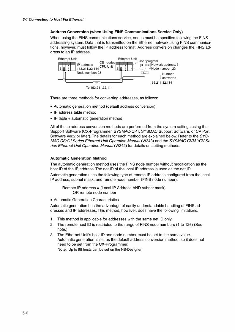
5-1 Connecting to Host Via Ethernet
5-6
Address Conversion (when Using FINS Communications Service Only)
When using the FINS communications service, nodes must be specified following the FINSaddressing system. Data that is transmitted on the Ethernet network using FINS communica-tions, however, must follow the IP address format. Address conversion changes the FINS ad-dress to an IP address.
There are three methods for converting addresses, as follows:
• Automatic generation method (default address conversion)
• IP address table method
• IP table + automatic generation method
All of these address conversion methods are performed from the system settings using theSupport Software (CX-Programmer, SYSMAC-CPT, SYSMAC Support Software, or CV PortSoftware Ver.2 or later). The details for each method are explained below. Refer to the SYS-MAC CS/CJ Series Ethernet Unit Operation Manual (W343) and the SYSMAC CVM1/CV Se-ries Ethernet Unit Operation Manual (W242) for details on setting methods.
Automatic Generation Method
The automatic generation method uses the FINS node number without modification as thehost ID of the IP address. The net ID of the local IP address is used as the net ID.
Automatic generation uses the following type of remote IP address configured from the localIP address, subnet mask, and remote node number (FINS node number).
Remote IP address = (Local IP Address AND subnet mask)OR remote node number
• Automatic Generation Characteristics
Automatic generation has the advantage of easily understandable handling of FINS ad-dresses and IP addresses. This method, however, does have the following limitations.
1. This method is applicable for addresses with the same net ID only.2. The remote host ID is restricted to the range of FINS node numbers (1 to 126) (See
note.).3. The Ethernet Unit’s host ID and node number must be set to the same value.
Automatic generation is set as the default address conversion method, so it does notneed to be set from the CX-Programmer.Note: Up to 98 hosts can be set on the NS-Designer.
Ethernet UnitCS1-seriesCPU Unit
Ethernet Unit
IP address:153.211.32.114Node number: 23 Data
Data
To 153.211.32.114
User program
153.211.32.114
Network address: 5Node number: 23
Numberconverted
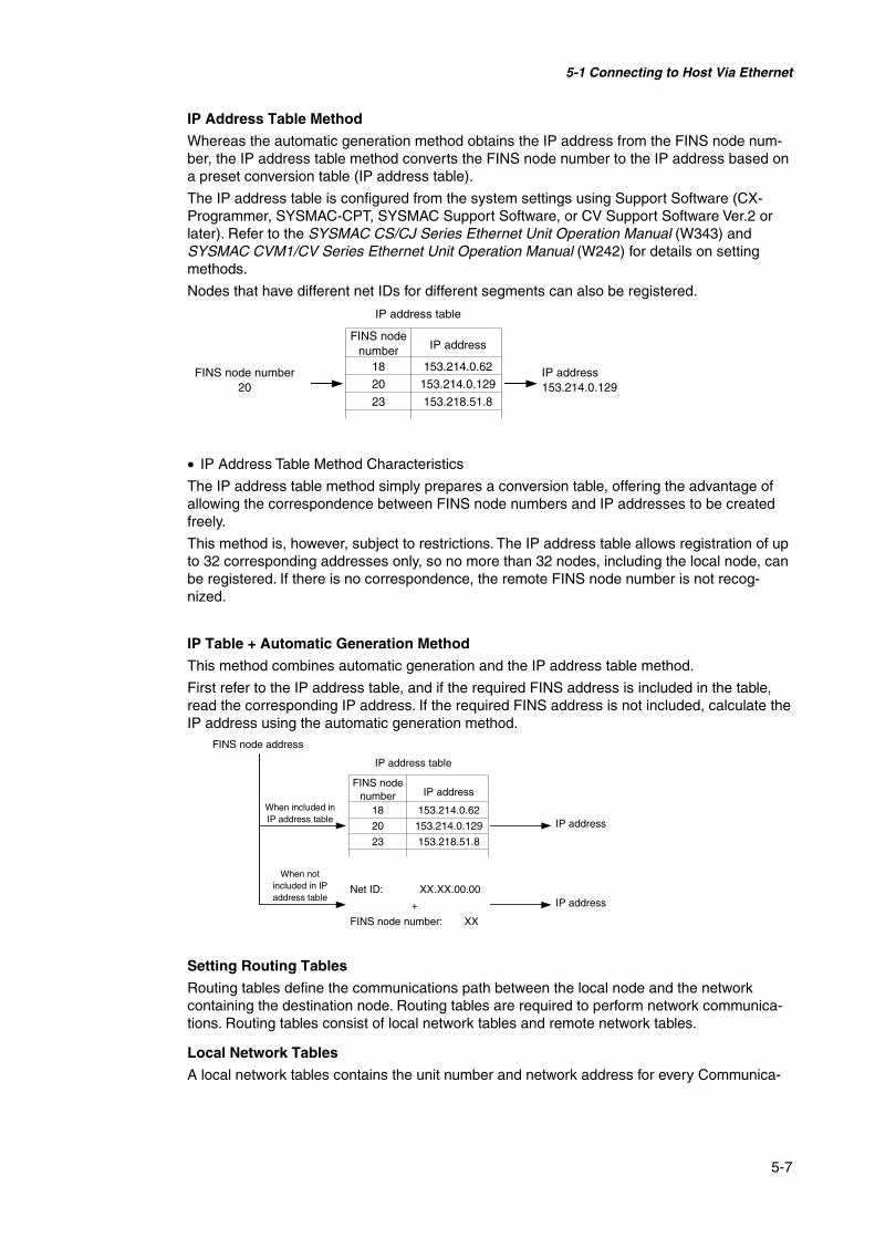
5-1 Connecting to Host Via Ethernet
5-7
IP Address Table Method
Whereas the automatic generation method obtains the IP address from the FINS node num-ber, the IP address table method converts the FINS node number to the IP address based ona preset conversion table (IP address table).
The IP address table is configured from the system settings using Support Software (CX-Programmer, SYSMAC-CPT, SYSMAC Support Software, or CV Support Software Ver.2 orlater). Refer to the SYSMAC CS/CJ Series Ethernet Unit Operation Manual (W343) andSYSMAC CVM1/CV Series Ethernet Unit Operation Manual (W242) for details on settingmethods.
Nodes that have different net IDs for different segments can also be registered.
• IP Address Table Method Characteristics
The IP address table method simply prepares a conversion table, offering the advantage ofallowing the correspondence between FINS node numbers and IP addresses to be createdfreely.
This method is, however, subject to restrictions. The IP address table allows registration of upto 32 corresponding addresses only, so no more than 32 nodes, including the local node, canbe registered. If there is no correspondence, the remote FINS node number is not recog-nized.
IP Table + Automatic Generation Method
This method combines automatic generation and the IP address table method.
First refer to the IP address table, and if the required FINS address is included in the table,read the corresponding IP address. If the required FINS address is not included, calculate theIP address using the automatic generation method.
Setting Routing Tables
Routing tables define the communications path between the local node and the networkcontaining the destination node. Routing tables are required to perform network communica-tions. Routing tables consist of local network tables and remote network tables.
Local Network Tables
A local network tables contains the unit number and network address for every Communica-
IP address
18
FINS nodenumber
IP address153.214.0.129
FINS node number20
IP address table
20
153.214.0.62
153.214.0.129
153.218.51.823
+
Net ID: XX.XX.00.00
IP address
18
FINS nodenumber
When notincluded in IPaddress table
When included inIP address table IP address
FINS node address
IP address table
20
153.214.0.62
153.214.0.129
153.218.51.823
FINS node number: XX
IP address

5-1 Connecting to Host Via Ethernet
5-8
tions Unit mounted at a node. If there is more than one Communications Unit at a node, eachUnit will contain a local network table.
Remote Network Table
The remote network table provides the node and network address corresponding to the initialrelay point (first point the data must pass) en route to a target network (end network) not di-rectly connected to the local PLC. The table specifies the route from the relay point to the endnetwork.
Routing tables are created using the CX-Programmer and then transferred to the host. Referto the CX-Programmer User Manual for actual procedures.
The methods for setting each Unit are described next.
• CS-series PLCs
Note • Always turn OFF the power to the PLC before setting the rotary switches.• Create I/O tables for the CPU Unit when setting the unit number for the first time or chang-
ing settings.
CS1G/CS1H and CS1G/CS1H-H Ethernet Units:
CS1W-ETN01CS1W-ETN11CS1W-ETN21
Unit number 04Unit number 02
Network 2
Network 3
Local network tableLocal networkaddress
Unit number
PT at localnode
Node 1 Node 2 Node 3
Relay PLC(a)
Node 2
Relay PLC(b)
Node 2 Desti-nation
Node 2
Network 1 Network 2 Network 3
Remote Network Table for Local PT
Meaning: To go to network 3,first go to node 3 of network 1.
Remote Network Table for PLC (a)
Destinationnetworkaddress
Relaynetworkaddress
Gatewaynodeaddress
Meaning: To go to network 3,first go to node 2 of network 2.
Local Network Table for PLC (b)Localnetworkaddress
Unitnumber
Relaynetworkaddress
Destinationnetworkaddress
Gatewaynodeaddress

5-1 Connecting to Host Via Ethernet
5-9
Setting the Front Panel Switches
Setting Unit Numbers
Always set the unit numbers so that the unit numbers of other CPU Bus Units mounted to theCPU Unit are all unique.
Use a small screwdriver to set the rotary switches, being careful not to damage them.
The factory setting is 0.
Setting range
0 to F
Setting Node Numbers
Setting range
01 to 7E (1 to 126 decimal)
Set the upper digit using the left rotary switch and the lower digit using the right rotary switch.
The factory setting is 01.
When converting addresses using the automatic generation method, set the node number tothe same value as that set for SW7 and SW8 of the local IP address setting switches, whichare described on the following pages. If the same values cannot be set, the IP address tablemethod or IP table + automatic generation method must be used to convert the addresses.
Setting the Rear Panel Switches
Setting Local IP Addresses
Set the local IP address for the Ethernet Unit using the eight hexadecimal rotary switches (lo-cal IP address setting switches), expressing each 4-bit value as a single hexadecimal digit.Set the IP address as a hexadecimal using the eight switches combining SW1 and SW2,SW3 and SW4, SW5 and SW6, and SW7 and SW8, as shown in the following diagram.
Setting range for each switch
0 to F
Local IP address
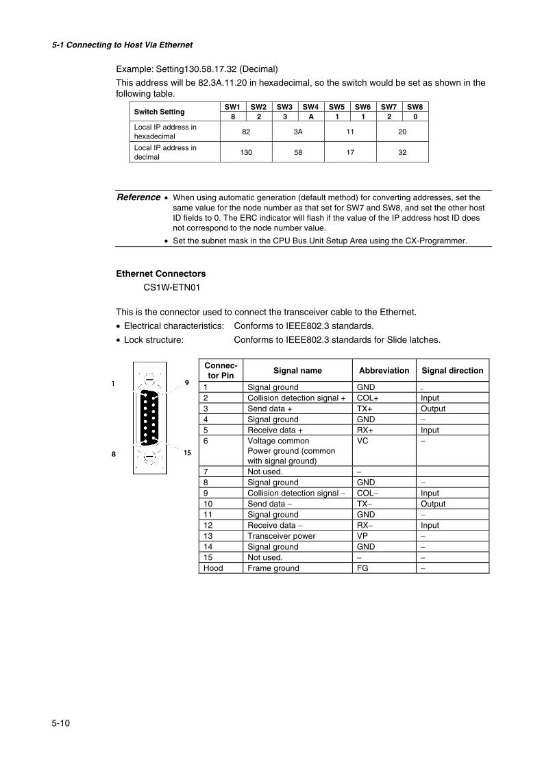
5-1 Connecting to Host Via Ethernet
5-10
Example: Setting130.58.17.32 (Decimal)
This address will be 82.3A.11.20 in hexadecimal, so the switch would be set as shown in thefollowing table.
SW1 SW2 SW3 SW4 SW5 SW6 SW7 SW8Switch Setting
8 2 3 A 1 1 2 0Local IP address inhexadecimal
82 3A 11 20
Local IP address indecimal
130 58 17 32
Reference • When using automatic generation (default method) for converting addresses, set thesame value for the node number as that set for SW7 and SW8, and set the other hostID fields to 0. The ERC indicator will flash if the value of the IP address host ID doesnot correspond to the node number value.
• Set the subnet mask in the CPU Bus Unit Setup Area using the CX-Programmer.
Ethernet Connectors
CS1W-ETN01
This is the connector used to connect the transceiver cable to the Ethernet.
• Electrical characteristics: Conforms to IEEE802.3 standards.
• Lock structure: Conforms to IEEE802.3 standards for Slide latches.
Connec-tor Pin
Signal name Abbreviation Signal direction
1 Signal ground GND .2 Collision detection signal + COL+ Input3 Send data + TX+ Output4 Signal ground GND −5 Receive data + RX+ Input6 Voltage common
Power ground (commonwith signal ground)
VC −
7 Not used. −8 Signal ground GND −9 Collision detection signal − COL− Input10 Send data − TX− Output11 Signal ground GND −12 Receive data − RX− Input13 Transceiver power VP −14 Signal ground GND −15 Not used. − −Hood Frame ground FG −

5-1 Connecting to Host Via Ethernet
5-11
CS1W-ETN11CS1W-ETN21
This is the connector used to connect the twisted-pair cable to the Ethernet.
• Electrical characteristics: Conforms to IEEE802.3 standards.
• Connector structure: RJ45 8-pin modular connector (conforms to ISO8877).
Connec-tor Pin
Signal name Abbreviation Signal direction
1 Send data + TD+ Output2 Send data − TD− Output3 Receive data + RD+ Input4 Not used. − −5 Not used. − −6 Receive data − RD- Input7 Not used. − −8 Not used. − −
• CJ-series PLCs
Note • Always turn OFF the power to the PLC before setting the rotary switches.• Create I/O tables for the CPU Unit when setting the unit number for the first time or chang-
ing settings.
CJ-series Ethernet Units:
CJ1W-ETN11CS1W-ETN21
Setting the Front Panel Switches
Setting Unit Numbers
Always set the unit numbers so that the unit numbers of other CPU Bus Units mounted to thesame CPU Unit are all unique.
Use a small screwdriver to set the rotary switches, being careful not to damage them.
The factory setting is 0.
Setting range
0 to F
Setting Node Numbers
Set the node numbers as hexadecimal values with the node number setting switch. Alwaysset the node numbers so that other Ethernet Units connected to the same Ethernet networkall have unique addresses. As long as the addresses are unique, they can be set between 01and 7E (1 to 126 decimal).
Setting range
01 to 7E (1 to 126 decimal)
1
8

5-1 Connecting to Host Via Ethernet
5-12
Set the upper digit using the top rotary switch and the lower digit using the bottom rotaryswitch.
The factory setting is 01.
When using automatic generation to convert addresses, set the node number to the samevalue as that of the rightmost byte of the local IP address. If the same values cannot be set,the IP address table method or combination method must be used to convert the addresses.
Setting Local IP Addresses
For CJ-series Ethernet Units, set the local IP address from the CX-Programmer or otherSupport Software for the CPU Unit. Refer to the SYSMAC CS/CJ Series Ethernet Unit Op-eration Manual (W343) for details on setting methods.
CJ1W-ETN11CS1W-ETN21
This is the connector used to connect the twisted-pair cable to the Ethernet.
• Electrical Characteristics: Conforms to IEEE802.3 standards.
• Connector Layout: RJ45 8-pin modular connector (conforms to ISO8877).
Connector Pin
Signal name Abbreviation Signal direction
1 Send data TD+ Output2 Send data − TD− Output3 Receive data + RD+ Input4 Not used. − −5 Not used. − −6 Receive data − RD− Input7 Not used. − −8 Not used. − −
• CV/CVM1-series (-V@) PLCs
Unit for CV500-CPU01-V1, CV1000-CPU01-V1, CV2000-CPU01-V1, CVM1-CPU01-V2,CVM1-CPU11-V2, and CVM1-CPU21-V2 CPU Units:
CV500-ETN01
Setting Rotary Switches
Set the unit number and node number with the two rotary switches on the front of the Unit.
Switch Layout
The layout of the two switches is shown in the following diagram.
1
8

5-1 Connecting to Host Via Ethernet
5-13
• Set the unit number using SW1 and SW2. Set the unit number so that it is different fromother CPU Bus Units in the system.
• Set the node number using SW3 and SW4.
Setting Range
Each switch can be set within the following range.
Settings Setting rangeUnit number (SW1, SW2) 00 to 15 (decimal)Node number (SW3, SW4) 01 to 7E hexadecimal (1 to 126 decimal)
Setting Unit Numbers
The unit number is used to identify each Unit when multiple CPU Bus Units are mounted tothe CPU Unit.
Use the left switch (SW1) to set the ten’s digit, and the right switch (SW2) to set the one’sdigit. Set between 00 and 15 decimal.
Setting Example
This example is for unit number 12.
Reference • The unit number cannot be set to a value more than 15. If the unit number is set to avalue higher than 15, the ERH indicator in the display will light.
• When more than one CPU Bus Unit is mounted to a single PLC, set each Unit with aunique unit number.
Setting Node Numbers
The node number is used to identify PLCs when more than one PLC is connected to theEthernet. This setting is the node number used for FINS communications.
Use the left switch (SW3) to set the left digit as a hexadecimal, and the right switch (SW4) toset the right digit. The setting range is 01 to 7E hexadecimal (1 to 126 decimal).
Setting Example:
This example is for node number 29 (decimal).
29 = 1 × 16 + 13 = 1D (hexadecimal)

5-1 Connecting to Host Via Ethernet
5-14
Reference • The node number cannot be set to a value higher than 7E (126 decimal). If the nodenumber is set to a higher value, an error will occur and the ERH indicator in the dis-play will light.
• Set the node numbers so that all the nodes in the same network are unique.
Setting IP Addresses for Ethernet Units
The IP address must also be set for Ethernet Units. Ethernet communications are not possi-ble if the IP address of the Ethernet Unit is not set.
Set the IP address for the Ethernet Unit from the CPU Bus Unit Setup Area using Program-ming Devices (SYSMAC-CPT, SYSMAC Support Software, CV Support Software Ver. 2 orlater, FIT20-MF501-V2, FIT10-MF501-V2, FIT20-MC601, or FIT20-MC701). Refer to theSYSMAC CVM1/CV Series Ethernet Unit Operation Manual (W242) for details on settingmethods.
Ethernet Unit System
Set the system settings for the Ethernet Unit to operate on the Ethernet network as a node.Set the system settings using a Programming Device (SYSMAC-CPT, SYSMAC SupportSoftware, CV Support Software Ver.2 or later, FIT20-MF501-V2、FIT10-MF501-V2, FIT20-MC601, or FIT20-MC701).
Reference • For details on operating the Support Software, refer to the CPU Bus Unit Setup Areain the SYSMAC Support Software Operation Manual: Networks (W201) and SYSMACSupport Software Operation Manual: CV Series (W249).
• Turn ON the power to the CPU Unit again after setting the system settings. The sys-tem settings are not enabled after setting them until the power has been turned ONagain.

5-2 Connecting to the Host Using Controller Link
5-15
5-2 Connecting to the Host Using Controller LinkThis section explains the method for connecting to the host using a Controller Link InterfaceUnit.
5-2-1 What Is a Controller Link Network?A Controller Link Network is an FA Network that can send and receive large data packetsflexibly and easily among the OMRON C200HX/HG/HE PLC Programmable Terminal (PTs),SYSMAC CS-series PLCs, CJ-series PLCs, CQM1H-series PLCs, C200HX/HG/HE PLCs,CVM1/CV-series PLCs, IBM PC/AT or compatible computers, and NS-series PTs. The Con-troller Link supports data links that enable data sharing and a message service that enablessending data and receiving data when required. Data link areas can be freely set to create aflexible data link system and effectively use data areas.
The network is connected using shielded twisted-pair cable or optical fiber cable. In addition,the Controller Link Network can transfer large quantities of data at high speed, so that it ispossible to construct a wide-area network easily that supports from low-level systems to high.For details on data links and message service, refer to the Controller Link Support Board Op-eration Manual (W307), Controller Link Support Board for PCI Bus Operation Manual (W383),and the Controller Link Unit Operation Manual (W309).
Note: An optical fiber cable is not available for NS-series PTs.
To connect the PT to the Controller Link, it is necessary to install a Controller Link InterfaceUnit on the PT. Refer to 3-8 Installing the Controller Link Interface Unit for the procedure forinstalling and wire the Controller Link Interface Unit.
When communicating by Controller Link, the network number, node number, routing tables,and data link tables must be set. For details, refer to Section 7 System Settings in the NS Se-ries Operation Manual.
Required Devices
To construct a Controller Link Network, the devices described in the following table are re-quired.
PLC,SYSMACCJ Series
CJ1W-CLK21Controller
PLC,SYSMACCQM1H
CQ1H-CLK21Controller LinkUnit
PLC,SYSMACCS Series
CS1W-CLK21ControllerLink Unit
PLC,SYSMACC200HX/HG/HE
C200HW-CLK21ControllerLink Unit PLC,
SYSMACCVM1/CVSeries
CVM1-CLK21ControllerLink Unit
NS-CLK21ControllerLink Inter-face Unit
IBM PC/AT orcompatible
FC98 per-sonal com-puter
Personalcomputer
3G8F5-CLK21Controller LinkSupport Board
3G8F6-CLK21Controller LinkSupport Board
3G8F7-CLK21Controller LinkSupport Board
NS SeriesNS12-TS@NT10-TV@
5-2 Connecting to the Host Using Controller Link
5-16
Device Model RemarksController Link Unit(See note.)
CVM1-CLK21C200HW-CLK21CS1W-CLK21CQM1H-CLK21CJ1W-CLK21
Required to connect PLC withController Link Network.
Controller Link Sup-port Board (ISABus/PC98)
3G8F5-CLK213G8F6-CLK21
Controller Link Sup-port Board (PCI Bus)
3G8F7-CLK21
Required to connect IBMPC/AT or compatible comput-ers with Controller Link Net-work.
Twisted-pair Cable ESVC0.5×2C Required to connect the PT,PLC, and IBM PC/AT or com-patible computers. Useshielded twisted-pair cable.
Controller Link WiredRelay Terminal Block
CJ1W-TB101 Used as a relay terminal blockfor wires and can be used asrequired to facilitate replace-ment and maintenance ofController Link Units andBoards after the communica-tions system has been started.
Note: For details on the CPU Units that support connection to Controller Link Units, refer to Appendix7 Standard Models.
5-2-2 Data LinksThis section outlines data links and the method of setting data link tables when using datalinks. For details, refer to the Controller Link Support Board Operation Manual (W307), Con-troller Link Unit Operation Manual (W309), and the Controller Link Support Board for PCI BusOperation Manual (W383).
What Are Data Links?Data links automatically exchange preset data between nodes (i.e., between PLCs, betweena PLC and an IBM PC/AT or compatible computer, or between a PLC and an NS-series PT).Data links can be freely created for CS-series PLCs, C200HX/HG/HE PLCs, CVM1, CV-series PLCs, CJ-series PLCs, CQM1H-series PLCs, and NS-series PTs.
Two data link areas, area 1 and area 2, can be set for each node. Data links can be set in ei-ther of the following ways.
• Data link areas can be set by inputting data link tables through the Controller Link SupportSoftware. Data link tables are created to define the data links. These tables enable free al-location of data link areas.
• Data links can be set automatically from a Programming Device. With automatically set datalinks, all link areas are the same size.
Automatic setting and manual setting cannot be used together in the same network.
The following rules apply to these methods of setting data links.
1. Data links are enables concurrently for area 1 and area 2.2. Separate settings (data link start words and send area size) are made in area 1 and area
2. The sequences of send and receive words are the same in area 1 and area 2.3. Not all nodes must participate in the data links.

5-2 Connecting to the Host Using Controller Link
5-17
Example 1: The order of sendand receive nodes is free.
Example 2: Some nodes cansend data without receiving data.
Example 3: Some nodes canreceive data without sendingdata.
Example 4: A node can receive aspecified number of words fromthe beginning of an area.
Area 1
Area 2
Area 1
Area 2
Area 1
Area 2
Area 1
Area 2
Sending only
Receiving only
Receiving only
Several wordsfrom thebeginning

5-2 Connecting to the Host Using Controller Link
5-18
Setting Data Link TablesTo perform data links, data link tables are required. Set data link tables by following the stepsbelow.
1. Set data link tables using the CX-Net (Network Configurations Tool).Data link tables are created to define data links. These tables must be set for each nodeparticipating in data links. Refer to the manual for CX-Programmer for the method of set-ting.The following table shows the items and setting range for data link tables in the ControllerLink Support Board mounted on the PT.
Setting item Setting rangePT Model Set as a "NSB."Node 1 to 32
Set the address of the refresh nodes.First data link statusword
If a number is set, it will be invalid because the first word to store data linkstatus is fixed.Set ”-“.
Area1 Data linkstart word(See note.)
$B0 to $B32767$W0 to $W24575Use CIO for $B and D for $W in the CX-Net.The same area cannot be set for both area 1 and area 2. Set different areas.
Number ofwords
• Remote nodes: 0 to the number of source wordsSet the number of words to be received
• Local nodes: 0 to 1000Set the number of words to be transmitted
The total number of words in area 1 and area 2 in each node must not exceed1,000.The number of words in both area 1 and area 2 in each node must not be setto 0.
Offset • Remote nodes: 0 to one less than number of source wordsSet offset for data to be received
• Local nodes: Cannot be set.This setting is not required if an offset is not used.
Area2 Data linkstart word(See note.)
$B0 to $B32767$W0 to $W24575Use CIO for $B and D for $W in the CX-Net.The same area cannot be set for both area 1 and area 2. Set different areas.
Number ofwords
• Remote nodes: 0 to the number of source wordsSet the number of words to be received
• Local nodes: 0 to 1000Set the number of words to be transmitted
The total number of words in area 1 and area 2 in each node must not exceed1,000.The number of words in both area 1 and area 2 in each node must not be setto 0.
Offset • Remote nodes: 0 to one less than number of source wordsSet offset for data to be received
• Local nodes: Cannot be set.This setting is not required if an offset is not used.

5-2 Connecting to the Host Using Controller Link
5-19
Note The following examples show how to change CIO and D addresses to $B and $W ad-dresses.
1. Changing to $B addresses:$B address = Word in CIO address (0 to 2047) × 16 + Bit in CIO address (00 to 15)Example: If the CIO address is 00100.04, $B address = 100 × 16 + 4 = $B1604.Word Bit
2. Changing to $W addresses:$W address = D address (0 to 24575)Example: If the D address is D00100, $W address = $W100.
• The total number of words set in area 1 and area 2 must not exceed 32,000.• Always delete the data link tables if the node does not participate in data links.
Save the data link tables after setting the above items.
2. Set data link tables for the PT side on the NS-DesignerThe two setting methods below can be used. Use the appropriate method for the applica-tion.1) Specifying data link tables with NS-Designer:
If the data link tables are set from the NS-Designer, then they cannot be changed viaa network. Even if they are temporarily changed from the CX-Server or Controller LinkSupport Software, they will return to the tables set from the NS-Designer the next timethe PT is started. To change the data link tables when they have been set from theNS-Designer, it is necessary to retransfer the project or setting file to the PT.Select Setting - System Setting on the NS-Designer, click the Controller Link Tab,and specify the data link tables created in step 1. Refer to Section 7 System Settingsin the NS-Designer Operation Manual, for specifying the data link table file.
2) Setting data link tables across a network:To do so, transfer the data link tables in the Controller Link Interface Unit from the CX-Server or Controller Link Support Software, and do not specify data link tables fromthe NS-Designer. If data link tables are set via a network, then they can later bechanged via a network as required. For details on the transfer method, refer to the CX-Net Operation Manual (W361) and the Controller Link Support Software OperationManual (W369).
3. Transfer the project created on NS-Designer to the PT.
Starting and Stopping Data LinksThe PT starts and stops data links according to the status of the data links when participatingin the network. If the data links are started when entering the network, the PT will start itsdata links. If network has stopped data links, the PT will not start data links. The PT cannotcontrol starting/stopping data links independently. Control starting/stopping data links on theController Link network using the startup node or CX-Server.
Note • The data link mode (manual setting or automatic setting) and data link method are deter-mined according to the data link setting in the startup node. In the startup node, set thedata link tables if manual settings are being used and data link automatic setting parame-ters if automatic settings are being used. If the settings are incorrect, the data links will notstart.

5-2 Connecting to the Host Using Controller Link
5-20
Caution• Check the following items before starting data links.
1. Manually Set Data LinksCheck the data link tables in each node participating inthe data link to see that they are correct. Be sure thatdata link tables are deleted from nodes that are not par-ticipating in the data links.
2. Automatically Set data LinksBe sure that the correct DM parameters have been setin the data link startup node.
If incorrect data link tables or parameters are set, injury mayresult due to unexpected operation of the system.
• Even if the correct data link tables or parameters have beenset, do not start or stop data links before verifying that therewill be no adverse influence on the system.
Setting Routing TablesRoutine tables that define the communications path from the local node to the network con-nected to the destination. Routine tables must be set for the following items.
• Local node
• All relay nodes that are included for the communication path from local node to the destina-tion.
Make settings for routing tables on the NS-Designer. Refer to Section 7 System Settings inthe NS-Designer Operation Manual for details on setting routing tables. For details on settingrouting tables for the PLC, refer to the Controller Link Unit Operation Manual (W309).
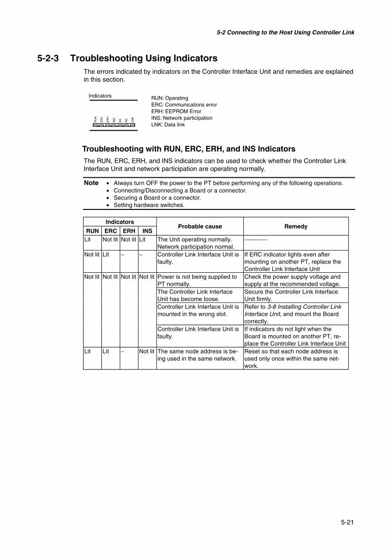
5-2 Connecting to the Host Using Controller Link
5-21
5-2-3 Troubleshooting Using IndicatorsThe errors indicated by indicators on the Controller Interface Unit and remedies are explainedin this section.
Indicators
LNK
RD
SD
INS
ER
H
ER
C
RU
N
Troubleshooting with RUN, ERC, ERH, and INS IndicatorsThe RUN, ERC, ERH, and INS indicators can be used to check whether the Controller LinkInterface Unit and network participation are operating normally.
Note • Always turn OFF the power to the PT before performing any of the following operations.• Connecting/Disconnecting a Board or a connector.• Securing a Board or a connector.• Setting hardware switches.
Indicators
RUN ERC ERH INSProbable cause Remedy
Lit Not lit Not lit Lit The Unit operating normally.Network participation normal.
Not lit Lit − − Controller Link Interface Unit isfaulty.
If ERC indicator lights even aftermounting on another PT, replace theController Link Interface Unit
Not lit Not lit Not lit Not lit Power is not being supplied toPT normally.
Check the power supply voltage andsupply at the recommended voltage.
The Controller Link InterfaceUnit has become loose.
Secure the Controller Link InterfaceUnit firmly.
Controller Link Interface Unit ismounted in the wrong slot.
Refer to 3-8 Installing Controller LinkInterface Unit, and mount the Boardcorrectly.
Controller Link Interface Unit isfaulty.
If indicators do not light when theBoard is mounted on another PT, re-place the Controller Link Interface Unit
Lit Lit − Not lit The same node address is be-ing used in the same network.
Reset so that each node address isused only once within the same net-work.
RUN: OperatingERC: Communications errorERH: EEPROM ErrorINS: Network participationLNK: Data link

5-2 Connecting to the Host Using Controller Link
5-22
Indicators Probable cause Remedy
RUN ERC ERH INSLit − Lit − Routing table setting error. Remake and set the routing tables
correctly, referring to Section 7 SystemSettings in the NS-Designer OperationManual. When the routing tables arenot being used, delete the routing ta-bles.
EEPROM error. Send a FINS command to the Con-troller Link Interface Unit to readstatus, correct the data where the errorhas occurred, and reset the Board. Ifthe error occurs again, replace theController Link Interface Unit.
Lit − − Not lit Terminating resistance is notset correctly.
Turn ON the terminating resistance atthe nodes at both ends of the networkand turn it OFF at all other nodes.
Cables are not connected cor-rectly.
Check the cable connections and re-connect correctly.
The node address is larger thanthe maximum node address setfor the network parameters.
Either reset the maximum node ad-dress using Controller Link SupportSoftware or reset the node address tobelow the maximum.
No other nodes exist. Ensure that 2 or more nodes existwithin the Network.
No nodes have been set aspolling node.
Set the polling node using the CX-Server.
The set baud rate is differentfrom other nodes.
Reset the baud rate for the ControllerLink in the System Settings of the NS-Designer. Refer to Section 7 SystemSettings in the NS-Designer OperationManual.

5-2 Connecting to the Host Using Controller Link
5-23
Troubleshooting with LNK Indicator
- Data Links Cannot Be Started
The following table describes the LNK indicator and remedies when a data link cannot bestarted.
Starting a data link depends on the Controller Link Interface Unit operating normally and par-ticipating in the network. Refer to Troubleshooting with RUN, ERC, ERH, and INS Indicatorsearlier in this section and check operation before using the following table.
Indicator
LNKProbable cause Remedy
Lit Data link operating normally. Flashing There is an error in the data link tables. If ERH or ERR indicator is lit, reset the
data link tables.When manual setting is used, either datalink tables have not been created for thestartup node or there is an error in thedata link tables.
Create the data link tables for the startupnode using the CX-Server.
Not lit Manually set data links are already oper-ating on the same Network.
Set data link tables for the local node.
Automatically set data links are alreadyoperating on the same Network.
Stop the data links, review and set theparameters in the startup node's DM area,and then restart.The PT cannot be the startup node forautomatic settings. Settings must be per-formed at Controller Link Unit on the PLC.
- Node Cannot Participate in Data Links
The following table describes the LNK indicator and remedies when a Node cannot partici-pate in the data links.
Data link participation in the network depends on the Controller Link Interface Unit operatingnormally and participating in the network. Refer to Troubleshooting with RUN, ERC, ERH, andINS Indicators earlier in this section and check operation before using the following table.
Indicator
LNKProbable cause Remedy
Lit Data Link operating normally. Flashing When manual setting is used, there is an
error in the data link table.Reset data link tables using the CX-Server.
Not lit When manual setting is used, there are noData Link Tables set for the local node.
Set the data link tables for the local node.
When automatic setting is used, the setupnode is not set to participate in the datalinks.
Stop the data links, remake and set theparameters in the Startup node’s DMArea, and then restart the data links.Setting must be performed at PLC on theController Unit side, because the Control-ler Link Interface Unit cannot be thestartup node for automatic settings. Fordetails, refer to the Controller Link UnitsOperation Manual.

Section 6
System Menu Operations
This section describes the methods for operating the System Menu.
This section also provides details on functions that are useful for NS-series PT applications andfor system maintenance.
6-1 Operating Modes and System Menu................................................................................ 6-3
6-1-1 Mode Configuration ................................................................................................. 6-3
6-1-2 System Menu Configuration..................................................................................... 6-3
6-1-3 Overview of Menu Items.......................................................................................... 6-4
6-1-4 Using the System Menu............................................................................................ 6-7
6-2 Initializing and Saving Data and Removing the Memory Card....................................... 6-9
6-2-1 Screen Data Area Format ....................................................................................... 6-10
6-2-2 Initializing or Saving the Alarm/Event History...................................................... 6-11
6-2-3 Initializing and Saving Data Log............................................................................ 6-12
6-2-4 Initializing and Saving the Operation Log ............................................................. 6-14
6-2-5 Initializing and Saving the Error Log..................................................................... 6-16
6-2-6 Language Selection ................................................................................................ 6-17
6-2-7 Removing the Memory Card .................................................................................. 6-17
6-3 PT Settings..................................................................................................................... 6-19
6-3-1 Start-up Wait Time................................................................................................. 6-21
6-3-2 Screen Saver ........................................................................................................... 6-21
6-3-3 Key Press Sound..................................................................................................... 6-22
6-3-4 Buzzer Sound ......................................................................................................... 6-22
6-3-5 Backlight ................................................................................................................ 6-23
6-3-6 Calendar Check ...................................................................................................... 6-23
6-3-7 Printer Type............................................................................................................ 6-24
6-3-8 Printing Mode......................................................................................................... 6-25
6-3-9 Changing Values in Device Monitor Setting.......................................................... 6-25
6-3-10 Contrast (NS5 Only)............................................................................................... 6-25
6-4 Project Settings .............................................................................................................. 6-27
6-4-1 Project Title ............................................................................................................ 6-27

6-4-2 Number of Labels................................................................................................... 6-28
6-4-3 Initial Screen........................................................................................................... 6-28
6-4-4 Initial Label ............................................................................................................ 6-28
6-4-5 Alarm/Event History Recording Method ............................................................... 6-28
6-4-6 Data Log Recording Method .................................................................................. 6-28
6-4-7 Operation Log Recording Method.......................................................................... 6-29
6-4-8 Error Log Recording Method ................................................................................. 6-29
6-4-9 System Memory ..................................................................................................... 6-29
6-5 Setting Passwords .......................................................................................................... 6-30
6-6 Communications Settings .............................................................................................. 6-31
6-6-1 Communications Conditions .................................................................................. 6-31
6-6-2 Setting 1:1 NT Link................................................................................................ 6-33
6-6-3 Setting High-speed 1:N NT Links (Standard, High-speed).................................... 6-33
6-6-4 Setting Ethernet ...................................................................................................... 6-34
6-6-5 Setting the Controller Link Network ...................................................................... 6-35
6-6-6 Setting Bar Code Readers....................................................................................... 6-36
6-6-7 Modem Settings...................................................................................................... 6-37
6-7 Screen Data Check......................................................................................................... 6-38
6-8 Special Screens .............................................................................................................. 6-39
6-8-1 Alarm History......................................................................................................... 6-40
6-8-2 Operation Log ........................................................................................................ 6-41
6-8-3 Error Log ................................................................................................................ 6-42
6-8-4 Device Monitor....................................................................................................... 6-43
6-8-5 Communication Test .............................................................................................. 6-45
6-8-6 Video Configuration............................................................................................... 6-46
6-8-7 USB Device List..................................................................................................... 6-48
6-8-8 Display Capture Data ............................................................................................. 6-49
6-8-9 Memory Card Transfers ......................................................................................... 6-50
6-8-10 External Application Startup .................................................................................. 6-51
6-8-11 Version Display...................................................................................................... 6-52
6-9 Hardware Check ............................................................................................................ 6-53
6-9-1 LCD Check............................................................................................................. 6-53
6-9-2 Touch Switch Check .............................................................................................. 6-54
6-10 Starting Operations ........................................................................................................ 6-55

6-1 Operating Modes and System Menu
6-3
6-1 Operating Modes and System Menu
The System Menu can be used to set various PT settings by operating the touch switches onthe screen. The following diagram shows the menu configuration in the System Menu. Referto 6-1-4 Using the System Menu for details on System Menu operations.
6-1-1 Mode ConfigurationThe NS-series PTs have the following operating modes.
Mode System Menu : Displays the System Menu, and sets each of the settings for the PT.
RUN mode: Displays screens, allows data input, and communicates with each device.
TRANSFER mode: Data transfer withNS-Designer:
Uploads and downloads screen data andsystem programs between the NS-Designer(computer) and PT.
Memory Card transfer : Uploads and downloads screen data andsystem programs via the Memory Card.
ERROR mode: Fatal error: Stops processing (operating) and displays error mes-sage.
Non-fatal error: Continues processing (operating) without displaying er-ror message.
6-1-2 System Menu ConfigurationThe System Menu items and functions are as follows:
System Menu Initialize:Save:
Initializes or saves operation log, alarm/event histories, data log,error log, and formats screen data, provides a function to re-move the Memory Card, and sets the system language.
PT: Sets the system startup waiting time, screen saver, key presssound, buzzer, backlight, and calendar check. Also makes thesettings for the printer connected to the PT.
Project: Displays the project title, number of labels, history recordingmethod, and addresses allocated to the system memory. Dis-plays and sets the screen numbers displayed at startup time.
Password: Sets and changes passwords for permitting functional objectinput.
Comm: Sets the communications conditions for serial ports A and B, amodem (data transfer), Host Link, Ethernet, and Controller Link.
Data Check: Checks the stored screen contents without communications.
Special Screen: Displays the operation log, alarm history, error log, devicemonitor, communication test, version display, and capture data,and performs video configuration. Also lists devices connectedto the USB port.
Hardware Check: Performs a hardware check, such as checking that the touchpanel is operating properly.

6-1 Operating Modes and System Menu
6-4
6-1-3 Overview of Menu ItemsThe following tables show the eight menu items and provide an overview of their contents.
1. Initialize Tab
Item Function Page
Screen Data Area Formats project data, such as screen data. P. 6-10Alarm/Event History Initializes or saves in the Memory Card as a CSV file the
alarm/event history data that has been generated during opera-tion.
P. 6-11
Data Log Initializes or saves in the Memory Card as a CSV file the data logdata that registers changes to the contents of an address, orsaves in the Memory Card as a CSV file.
P. 6-12
Operation Log Initializes or saves in the Memory Card as a CSV file the operationlog data, such as that for functional object operations and screenswitching.
P. 6-14
Error Log Initializes or saves in the Memory Card as a CSV file the error logdata that is generated by macro errors.
P. 6-16
System language The language to display system menus, input keypads, error mes-sages, etc., can be set to Japanese or English.
P. 6-17
Memory Card The Memory Card in the PT can be removed. P. 6-17
2. PT Settings Tab
Item Function Page
Start-up Waiting Time Sets the system startup waiting time. Communications are notperformed during this specified time when the power is turned ONor the PT is reset. The default is 0 s.
P. 6-21
Screen Saver Sets the screen saver to ON or OFF. The default setting is OFF. P. 6-21Screen Saver Start-upTime
Sets the amount of time after which the screen saver is started.The default setting is 15 min.
P. 6-21
Key Press Sound Sets whether a sound will be heard when a touch switch ispressed. The default setting is ON.
P. 6-22
Buzzer Sound Sets whether a buzzer will be heard when a command from thehost is received or an error occurs. The default setting is ERR ON.
P. 6-22
Backlight Sets the backlight brightness to one of three levels. The bright-ness cannot be adjusted much.The default setting is High.
P. 6-23
Calendar Check Displays and sets the date and time for the internal clock. P. 6-23Printer Type Sets the control method for the printer connected to the PT. P. 6-24Mode Sets the printing method for the printer connected to the PT. P. 6-25Changing Value in DeviceMonitor Setting
Selects whether to set or just monitor device monitor values in thefunctions for Registered Monitor and 6-3-9 Switch Box.
P. 6-25
Contrast (NS5 only) Adjusts the contrast for the screen. P. 6-25

6-1 Operating Modes and System Menu
6-5
3. Project Tab
Item Function Page
Project Title Displays the project title. P. 6-27Number of Labels Displays the number of corresponding labels. P. 6-28Initial Screen Sets and displays the screen numbers first displayed after the
power is turned ON.P. 6-28
Initial Label Sets and displays the label number shown on the screen after thepower is turned ON.
P. 6-28
Alarm/Event RecordingMethod
Displays the method for recording the alarm/event histories. P. 6-28
Data Log RecordingMethod
Displays the method for recording the data log. P. 6-28
Operation Log RecordingMethod
Displays the method for recording the operation log. P. 6-29
Error Log RecordingMethod
Displays the method for recording the error log. P. 6-29
System Memory ($SB) Displays the allocated addresses of the system bit memory ($SB). P. 6-29System Memory ($SW) Displays the allocated address of the system word memory ($SW). P. 6-29
4. Password Tab
Item Function PageLevel 1 Changes the level 1 password. P. 6-30Level 2 Changes the level 2 password. P. 6-30Level 3 Changes the level 3 password. P. 6-30Level 4 Changes the level 4 password. P. 6-30Level 5 Changes the level 5 password. P. 6-30
5. Comm Tab
Item Function Page
Comms. Auto-returnSelects whether automatic recovery is used when a communica-tions error occurs.
P. 6-31
Timeout interval Sets and displays the timeout monitor time. P. 6-31Retry Counts Sets and displays the number of communications retries. P. 6-32Serial Port A Sets and displays whether serial port A is used, the communica-
tions method, and other details.P. 6-32
Serial Port B Sets and displays whether serial port B is used, the communica-tions method, and other details.
P. 6-32
Expansion Interface Sets and displays the connector used by serial port B (NS5 only). P. 6-33
EthernetSets and displays whether Ethernet is used and communicationsdetails.
P. 6-34
Controller LinkSets and displays whether Controller Link is used and communi-cations details.
P. 6-35
6. Data Check Tab
Item Function PageScreen Number Sets the screen number that is displayed as a sample. P. 6-38Show Address Displays the communications addresses set for the sample dis-
play.P. 6-38

6-1 Operating Modes and System Menu
6-6
7. Special Screen Tab
Item Function PageAlarm History Displays the alarm history screen. P. 6-40Operation Log Displays the screen for recording the operation log. P. 6-41Error Log Displays the screen for recording the error log. P. 6-42Special Functions Displays the device monitor screen and communications test
screen. This function also starts external applications, lists USBdevices, performs Video Configuration, and displays capturedata.
P. 6-43
System Version Displays the version display screen. P. 6-52
8. Hardware Check Tab
Item Function PageLCD Check Checks the LCD. P. 6-53Touch Switch Check Checks the touch switches. P. 6-54

6-1 Operating Modes and System Menu
6-7
6-1-4 Using the System MenuInformation on using the menus, such as displaying the System Menu, and selecting menuitems, is provided here.
Reference The system settings set in the project data are given priority over those set in the Sys-tem Menu.
@ Displaying the System Menu
The System Menu can be displayed in four ways, as follows:
1. Press two of the four corners of the touch panel.2. Press the command button in the System Menu display.3. Press a command button set to switch the screen to the system menu.4. Specify screen number 4002 BCD (FA2 binary) and switch the screen.
1. Pressing the Corners of the Touch Panel
The System Menu can be displayed by pressing two of the four corners of the PT touch panelsimultaneously, as shown in the following diagram.
When pressing the corners of the touch panel, however, first press a corner that does nothave a functional object displayed. If the position of a functional object is pressed, its functionwill be performed. If the command button for switching screens is kept pressed after thescreen has been switched, it will be detected as if the button has been released.
The second corner pressed can be any of the other three corners. The System Menu will bedisplayed even if functional objects are displayed.

6-1 Operating Modes and System Menu
6-8
2. Pressing the Command Button in the System MenuWhile creating screens, if a command button for displaying the System Menu is created in thescreen, the System Menu can be displayed by pressing this command button.
3. Pressing Command Buttons to Switch Screens
The Screen Switch command button functions include a Indirect Specification of Screen No.function. Store the BCD value 4002 (binary FA2) in the communications address for indirectspecification and press the command button.
Refer to 2-9 Buttons in the Programming Manual for information on command buttons.
4. Storing 4002 in $SW0 (in System Memory)
A BCD value of 4002 (binary FA2) can be stored in $SW0 (in System Memory). Refer to 2-4System Memory in the NS Series Programming Manual for information on the system mem-ory.
@ Selecting Menu ItemsItems in the System Menu can be displayed by simply pressing the tab of the menu item to bedisplayed.
Example: Press the Hardware Check Tab in the System Menu to display the HardwareCheck Screen.
@ Switching to RUN Status from the System MenuPress the Exit Button to return to RUN mode.
Select the tab.

6-2 Initializing and Saving Data and Removing the Memory Card
6-9
6-2 Initializing and Saving Data and Removing theMemory Card
The Initialize Tab is used to initialize or save the PT data and specify the system language.Used these function whenever necessary.
• Memory Card (remove)
• Alarm/event history (initialize, save)
• Data log (initialize, save)
• Operation log initialization (initialize, save)
• Error log (initialize, save)
• Screen data area (format)
NS12 Data Initialize Screen
NS10/NS8 Data Initialize Screen
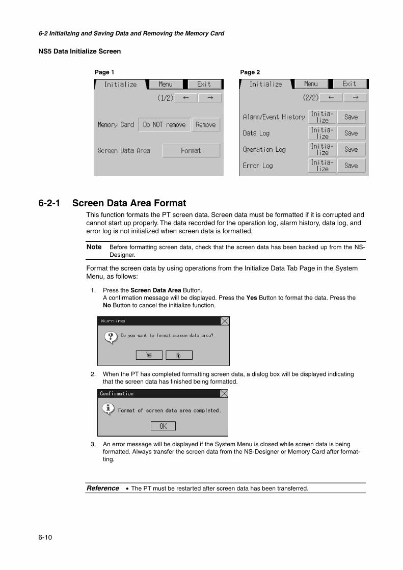
6-2 Initializing and Saving Data and Removing the Memory Card
6-10
NS5 Data Initialize Screen
6-2-1 Screen Data Area FormatThis function formats the PT screen data. Screen data must be formatted if it is corrupted andcannot start up properly. The data recorded for the operation log, alarm history, data log, anderror log is not initialized when screen data is formatted.
Note Before formatting screen data, check that the screen data has been backed up from the NS-Designer.
Format the screen data by using operations from the Initialize Data Tab Page in the SystemMenu, as follows:
1. Press the Screen Data Area Button.A confirmation message will be displayed. Press the Yes Button to format the data. Press theNo Button to cancel the initialize function.
2. When the PT has completed formatting screen data, a dialog box will be displayed indicatingthat the screen data has finished being formatted.
3. An error message will be displayed if the System Menu is closed while screen data is beingformatted. Always transfer the screen data from the NS-Designer or Memory Card after format-ting.
Reference • The PT must be restarted after screen data has been transferred.
Page 1 Page 2
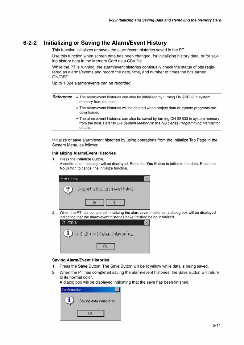
6-2 Initializing and Saving Data and Removing the Memory Card
6-11
6-2-2 Initializing or Saving the Alarm/Event HistoryThis function initializes or saves the alarm/event histories saved in the PT.
Use this function when screen data has been changed, for initializing history data, or for sav-ing history data in the Memory Card as a CSV file.
While the PT is running, the alarm/event histories continually check the status of bits regis-tered as alarms/events and record the date, time, and number of times the bits turnedON/OFF.
Up to 1,024 alarms/events can be recorded.
Reference • The alarm/event histories can also be initialized by turning ON $SB32 in systemmemory from the host.
• The alarm/event histories will be deleted when project data or system programs aredownloaded.
• The alarm/event histories can also be saved by turning ON $SB33 in system memoryfrom the host. Refer to 2-4 System Memory in the NS Series Programming Manual fordetails.
Initialize or save alarm/event histories by using operations from the Initialize Tab Page in theSystem Menu, as follows:
Initializing Alarm/Event Histories1. Press the Initialize Button.
A confirmation message will be displayed. Press the Yes Button to initialize the data. Press theNo Button to cancel the initialize function.
2. When the PT has completed initializing the alarm/event histories, a dialog box will be displayedindicating that the alarm/event histories have finished being initialized.
Saving Alarm/Event Histories
1. Press the Save Button. The Save Button will be lit yellow while data is being saved.
2. When the PT has completed saving the alarm/event histories, the Save Button will returnto its normal color.A dialog box will be displayed indicating that the save has been finished.
6-2 Initializing and Saving Data and Removing the Memory Card
6-12
6-2-3 Initializing and Saving Data LogThis function initializes or saves the data log saved in the PT.
Use this function when screen data has been changed, or for initializing history data. Thedata log is used to record changes over time to the contents of an address that is registeredin the log.
Up to 50,000 events can be recorded.
Reference • The data log for the specified group can be initialized by setting the group number in$SW37 and turning ON $SB35 in the system memory from the host. The data logs forall groups can be initialized by setting $SW37 to 0.
• The data log will be deleted when project data or system programs are downloaded.
• The data log for the specified group can be saved by setting the group number in$SW37 and turning ON $SB36 in the system memory from the host. The data logs forall groups can be saved by setting $SW37 to 0.
Initialize or save the data log by using operations from the Initialize Tab Page in the SystemMenu, as follows:
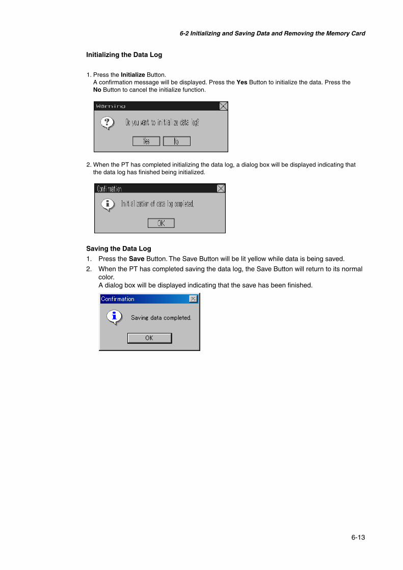
6-2 Initializing and Saving Data and Removing the Memory Card
6-13
Initializing the Data Log
1. Press the Initialize Button.A confirmation message will be displayed. Press the Yes Button to initialize the data. Press theNo Button to cancel the initialize function.
2. When the PT has completed initializing the data log, a dialog box will be displayed indicating thatthe data log has finished being initialized.
Saving the Data Log
1. Press the Save Button. The Save Button will be lit yellow while data is being saved.
2. When the PT has completed saving the data log, the Save Button will return to its normalcolor.A dialog box will be displayed indicating that the save has been finished.

6-2 Initializing and Saving Data and Removing the Memory Card
6-14
6-2-4 Initializing and Saving the Operation LogThis function initializes or saves the operation log saved in the PT.
Up to 1,024 operations can be recorded in order of occurrence.
Use this function when screen data has been changed, for initializing log data, or for savinglog data as a CSV file in the Memory Card.
The operation log is used to record the number of times the following operations are per-formed and the order in which they occur.
• Functional object operation history
• Screen display history
• Macro execution history
Refer to 2-4 System Memory in the PT Programming Manual for details.
Reference • The functional objects that can be recorded are ON/OFF buttons, word buttons, Nu-meral Display & Input, String Display & Input, and thumbwheel switches.
• The operation log data can also be initialized by setting the system bit memory ad-dress $SB37 to ON from the host.
• The operation log will be deleted when project data or system programs are down-loaded.
• The operation log can also be saved by turning ON $SB38 in system memory fromthe host. Refer to 2-4 System Memory in the PT Programming Manual for details.
Initialize or save the operation log by using operations from the Initialize Tab Page in the Sys-tem Menu, as follows:

6-2 Initializing and Saving Data and Removing the Memory Card
6-15
Initializing the Operation Log1. Press the Initialize Button.
A confirmation message will be displayed. Press the Yes Button to initialize the data. Press theNo Button to cancel the initialize function.
2. When the PT has completed initializing the operation log, a dialog box will be displayed indi-cating that the operation log has finished being initialized.
Saving the Operation Log
1. Press the Save Button. The Save Button will be lit yellow while data is being saved.
2. When the PT has completed saving the operation log, the Save Button will return to itsnormal color.A dialog box will be displayed indicating that the save has been finished.
Reference • When saving the operation log, the operation log must be controlled from the systemmemory. For details on controlling the operation log, refer to 2-4 System Memory inthe PT Programming Manual.
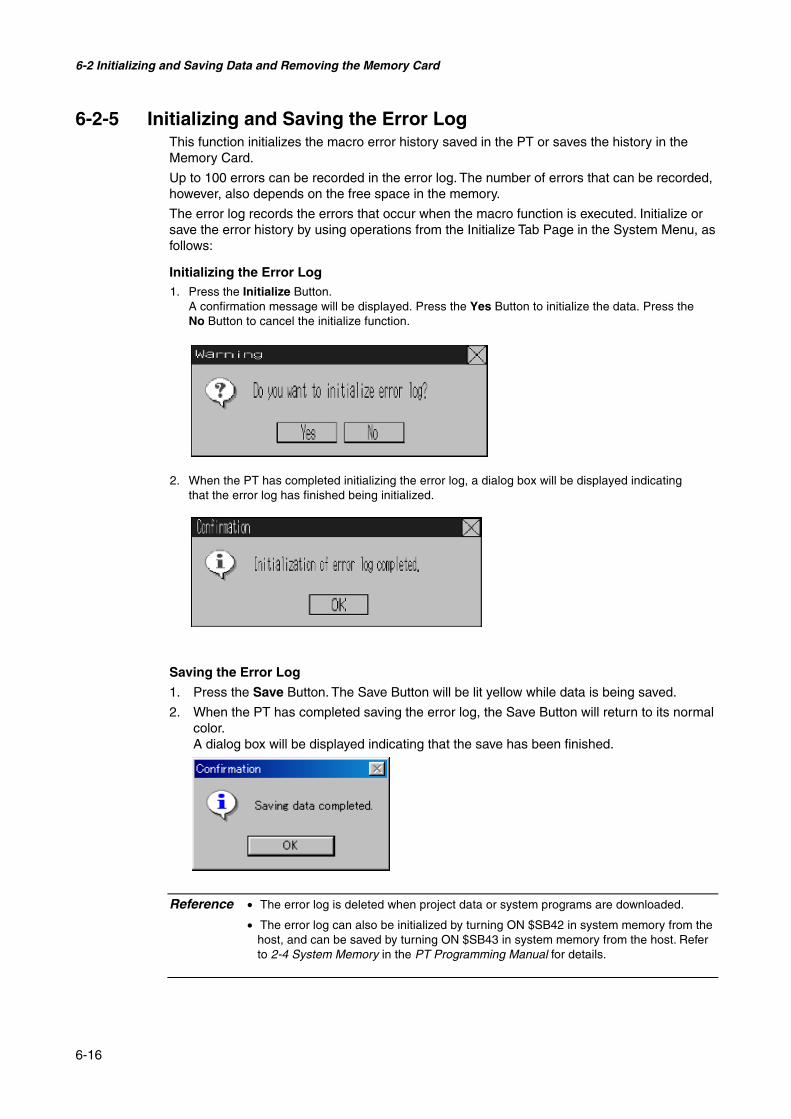
6-2 Initializing and Saving Data and Removing the Memory Card
6-16
6-2-5 Initializing and Saving the Error LogThis function initializes the macro error history saved in the PT or saves the history in theMemory Card.
Up to 100 errors can be recorded in the error log. The number of errors that can be recorded,however, also depends on the free space in the memory.
The error log records the errors that occur when the macro function is executed. Initialize orsave the error history by using operations from the Initialize Tab Page in the System Menu, asfollows:
Initializing the Error Log1. Press the Initialize Button.
A confirmation message will be displayed. Press the Yes Button to initialize the data. Press theNo Button to cancel the initialize function.
2. When the PT has completed initializing the error log, a dialog box will be displayed indicatingthat the error log has finished being initialized.
Saving the Error Log
1. Press the Save Button. The Save Button will be lit yellow while data is being saved.
2. When the PT has completed saving the error log, the Save Button will return to its normalcolor.A dialog box will be displayed indicating that the save has been finished.
Reference • The error log is deleted when project data or system programs are downloaded.
• The error log can also be initialized by turning ON $SB42 in system memory from thehost, and can be saved by turning ON $SB43 in system memory from the host. Referto 2-4 System Memory in the PT Programming Manual for details.

6-2 Initializing and Saving Data and Removing the Memory Card
6-17
6-2-6 Language SelectionThe system language can be set to either Japanese or English. The system language will beused on the system menu, input keypads, message dialog boxes, etc, on the PT.
The system language is set from the Initialize Tab Page in the System Menu Window usingthe following procedure.
1. Select either Japanese or English in the Select Language Area.
2. After specifying the language, click the Write Button. The system language will beswitched after the new setting has been saved.
Reference If ASCII codes are set as the character display format for String Display & INPUT, listdisplay, or data block tables (character fields), the following character codes will beused depending on the system language that is set.
System Language Character display Example (charactercode B5)
Japanese Shift-JIS codeEnglish Latin 1code µ
The above codes will also be used when indirect specifications are made for labelstrings for label objects.
6-2-7 Removing the Memory CardThe Memory Card can be removed from the PT while the PT is ON. Use the following proce-dure from the Initialize Tab Page of the System Menu to remove the Memory Card.
1. Press the Remove Button next to Memory Card.
2. The following dialog box will be displayed when it is safe to remove the Memory Card.Press the OK Button.
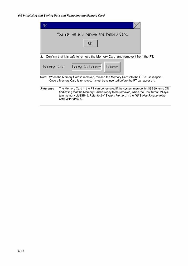
6-2 Initializing and Saving Data and Removing the Memory Card
6-18
3. Confirm that it is safe to remove the Memory Card, and remove it from the PT.
Note: When the Memory Card is removed, reinsert the Memory Card into the PT to use it again.Once a Memory Card is removed, it must be reinserted before the PT can access it.
Reference The Memory Card in the PT can be removed if the system memory bit $SB50 turns ON(indicating that the Memory Card is ready to be removed) when the Host turns ON sys-tem memory bit $SB49. Refer to 2-4 System Memory in the NS Series ProgrammingManual for details.

6-3 PT Settings
6-19
6-3 PT Settings
The PT Tab Page is used to set the following functions.
• Start-up wait time
• Screen saver
• Key press sound
• Buzzer sound
• Backlight
• Calendar check
• Printer type
• Mode
• Changing values
• Contrast (NS5 only)
PT Tab Page (Page 1) for the NS12 (Page 2)
PT Tab Page (Page 1) for the NS10 and NS8(NS10 has no contrast adjustment.) (Page 2)

6-3 PT Settings
6-20
PT Tab Page (Page 1) for the NS5 (Page 2)
(Page 3) (Page 2)
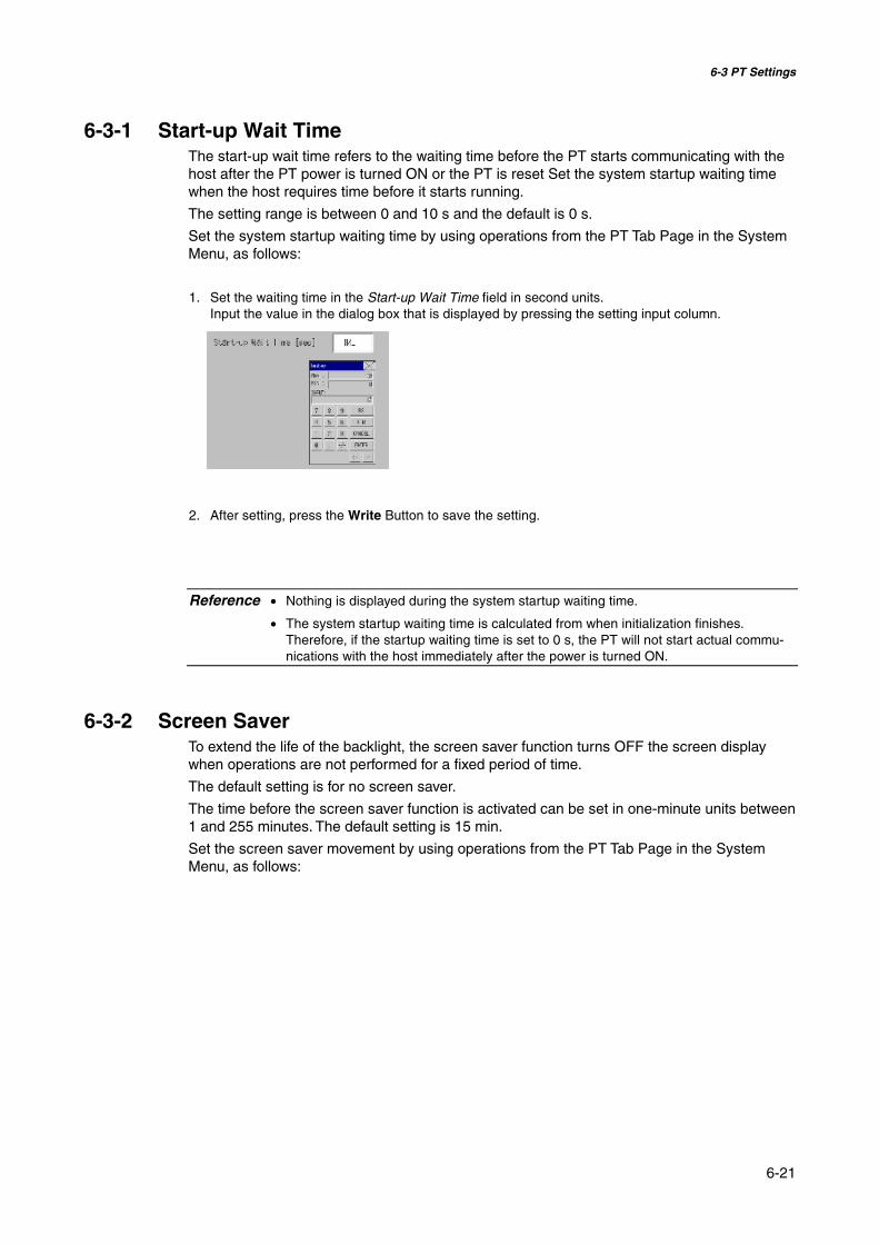
6-3 PT Settings
6-21
6-3-1 Start-up Wait TimeThe start-up wait time refers to the waiting time before the PT starts communicating with thehost after the PT power is turned ON or the PT is reset Set the system startup waiting timewhen the host requires time before it starts running.
The setting range is between 0 and 10 s and the default is 0 s.
Set the system startup waiting time by using operations from the PT Tab Page in the SystemMenu, as follows:
1. Set the waiting time in the Start-up Wait Time field in second units.Input the value in the dialog box that is displayed by pressing the setting input column.
2. After setting, press the Write Button to save the setting.
Reference • Nothing is displayed during the system startup waiting time.
• The system startup waiting time is calculated from when initialization finishes.Therefore, if the startup waiting time is set to 0 s, the PT will not start actual commu-nications with the host immediately after the power is turned ON.
6-3-2 Screen SaverTo extend the life of the backlight, the screen saver function turns OFF the screen displaywhen operations are not performed for a fixed period of time.
The default setting is for no screen saver.
The time before the screen saver function is activated can be set in one-minute units between1 and 255 minutes. The default setting is 15 min.
Set the screen saver movement by using operations from the PT Tab Page in the SystemMenu, as follows:

6-3 PT Settings
6-22
1. Select either OFF or Display Erased for the screen saver.2. If Display Erased is selected, set the screen saver startup time.
Input the value in the dialog box that is displayed by pressing the setting input column.
3. After setting, press the Write Button to save the setting.
Reference Pressing any part of the touch panel will cancel the screen saver and display the previ-ously displayed screen. When canceling the screen saver, If the part of the touch panelcorresponds to the input for a functional object, the screen saver will be cancelled only.The input for the functional object will not be processed.
6-3-3 Key Press SoundThis function sets whether an input sound is heard when the touch switches that allow inputfunctions for the PT are pressed.
ON: Input sound is heard when the touch switches that allow input functions for thePT are pressed.
OFF: Input sound is not heard when the touch switches that allow input functions forthe PT are pressed.
The default setting is ON.
1. Select either ON or OFF for the touch switch input sound.
2. After setting, press the Write Button to save the setting.
6-3-4 Buzzer SoundThe buzzer is used at times such as when a command from the host is received or an erroroccurs. This function is set to ON or OFF in the System Menu.
ON: Buzzer turns ON when a command is received from the host or an erroroccurs.
OFF: Buzzer is OFF.ERR ON: Buzzer turns ON when an error occurs only.
The default setting is ERR ON.

6-3 PT Settings
6-23
Reference • Other commands and settings associated with the buzzer exist, but the settings herehave the highest priority.
• When the buzzer is set to ON or ERR ON, the buzzer will be heard when messagesare displayed with a cross (X) or exclamation mark (!) icon.
• Refer to 2-17 Special Functions in the Programming Manual for details on the buzzerfunction.
Set the buzzer to ON/OFF by using operations from the PT Tab Page in the System Menu, asfollows:
1. Select either ON, OFF, or ERR ON for the buzzer setting.
2. After setting, press the Write Button to save the setting.
6-3-5 BacklightThis function sets the backlight brightness to one of three levels.
The default setting is high.
Set the brightness of the backlight by using operations from the PT Tab Page in the SystemMenu, as follows:
3. Select one of the three backlight brightness levels to set to high, middle, or low.
4. After setting, press the Write Button to save the setting.
6-3-6 Calendar CheckThis function displays the time and date of the PT’s internal system clock.
The factory settings for the date and time are not correct.
Set and display the date and time by using operations from the PT Tab Page in the SystemMenu, as follows:
1. The currently set date and time will be displayed in the Date and Time Setting field.2. To change the date/time, set the date/time in the dialog box that is displayed by pressing the
date and time field.

6-3 PT Settings
6-24
• Use the following input format to set the date:yyyy.mm.dd (yyyy: year, mm: month, dd: day)
Set the year using four digits.Example: Set March 15, 2002 as 2002.3.15. (Adding 0 prefix to single-digit settings is not required.)
• Use the following input format to set the time.hh.mm.ss (hh: hour, mm: minute, ss: second)
Set the year using the 24-hour clock.Example: Set 06:01:01 p.m. as 18.1.1. (Adding 0 prefix to single-digit settings is not required.)
3. Press the Enter Button to enable the settings.
6-3-7 Printer Type
If there is a printer connected to the PT, select the printer’s control method.
Setting item DetailsESC/P Raster Sets the printer’s control method to ESC/P Raster. Use this setting if
mainly using Epson printers.BJ Raster Sets the printer’s control method to BJ Raster. Use this setting if
mainly using Canon printers.
1. Select either ESC/P Raster or BJ Raster in Printer Type.
2. After setting, press the Write Button to save the setting.

6-3 PT Settings
6-25
6-3-8 Printing Mode
If there is a printer connected to the PT, select the printer’s control method.
Setting item DetailsColor Prints in color.Monochrome Prints in monochrome.Monochrome (Inverse) Prints in inverted monochrome.
1. Select Color, Monochrome, or Monochrome (Inverse) in Mode.
2. After setting, press the Write Button to save the setting.
6-3-9 Changing Values in Device Monitor SettingThis setting enables using the registered monitor and switch box functions of the devicemonitor only for monitoring by prohibiting address changes while monitoring.
Disable Button: Prohibits changing monitor valuesEnable Button: Enables changing monitor values (factory default)
This setting can also be made with the NS-Designer on the PT Operation Tab Page of theSystem Settings.
6-3-10 Contrast (NS5 Only)This function adjusts the screen contrast. Contrast can be adjusted in 100 degrees.
Adjust the contrast by using operations from the PT Tab Page in the System Menu, as fol-lows:

6-3 PT Settings
6-26
1. Change the contrast setting using the left and right arrow buttons (<<, <, >, >>) for contrast ad-justment. The contrast will change as soon as the buttons are pressed.
<< Button: Decreases the contrast by ten degrees. < Button: Decreases the contrast by one degree. > Button: Increases the contrast by one degree. >> Button: Increases the contrast by ten degrees.
Check the contrast from the sample display of eight shades above the arrow buttons.
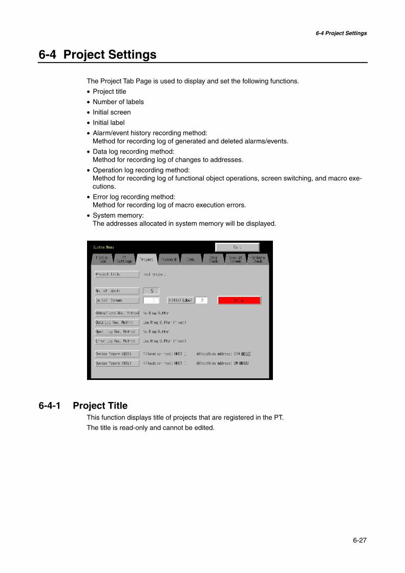
6-4 Project Settings
6-27
6-4 Project Settings
The Project Tab Page is used to display and set the following functions.
• Project title
• Number of labels
• Initial screen
• Initial label
• Alarm/event history recording method:Method for recording log of generated and deleted alarms/events.
• Data log recording method:Method for recording log of changes to addresses.
• Operation log recording method:Method for recording log of functional object operations, screen switching, and macro exe-cutions.
• Error log recording method:Method for recording log of macro execution errors.
• System memory:The addresses allocated in system memory will be displayed.
6-4-1 Project TitleThis function displays title of projects that are registered in the PT.
The title is read-only and cannot be edited.

6-4 Project Settings
6-28
6-4-2 Number of LabelsMultiple label data can be created in each project. This function displays the number of labelsset for the project that is registered in the PT.
The number of labels is read-only and cannot be edited.
Reference • Refer to 3-9 Project Properties in the NS-Designer Operation Manual for informationon setting multiple labels for a project.
• Refer to Labels in 2-8 Common Functional Object Functions in the ProgrammingManual for information on how to set multiple labels for a functional object.
6-4-3 Initial ScreenThis function displays and sets the screen number of the screen that is first displayed whenthe PT is started.Display and set the initial screen number by using operations from the Project Tab Page inthe System Menu, as follows:
1. The number of the screen that is displayed when the PT is started is displayed in the initialscreen field.
2. To change the initial screen number, input the value using the tenkey, which is displayed bypressing the display area.
3. After setting, press the Write Button to save the setting.
Reference The initial screen number can also be set from the NS-Designer.
6-4-4 Initial LabelThis function displays and sets the label number that is shown on the screen when the PT isstarted.
Reference This initial label number can also be set from the NS-Designer.
6-4-5 Alarm/Event History Recording MethodThis function displays the method for recording the alarm/event histories. The alarm/eventhistory recording method is read-only and cannot be edited.This alarm/event history recording method is set from the NS-Designer.
If a ring buffer is used, when the specified number of records is exceeded, the oldest data isdeleted and the new data is recorded.
If the ring buffer is not used, the PT stops collecting history data when the specified numberof records has been reached. Initialize the alarm/event histories to reopen the history records.
Reference Refer to 6-2-2 Alarm/Event History Initialization for details on initializing the alarm/eventhistories.
6-4-6 Data Log Recording MethodThis function displays the data log recording method.
The data log recording method is read only and cannot be edited.
The use of a ring buffer for the data log recording method is fixed.

6-4 Project Settings
6-29
When the specified number of log entries is exceeded, the oldest data is deleted and the newdata is recorded.
Use the NS-Designer to set the number of log entries.
Reference Refer to 6-2-3 Data Log Initialization in this manual and Data Log Function in 2-18 Spe-cial Functions in the Programming Manual for details on the data log.
6-4-7 Operation Log Recording MethodThis function displays the method for recording the operation log. The operation log recordingmethod is read only and cannot be edited. This operation log recording method is set from theNS-Designer.
If Save in Ring Buffer Format is set, when the specified number of items is exceeded, theoldest data is deleted and the new data is recorded.
If the log is not saved in ring buffer format, the PT stops collecting log data when the specifiednumber of items has been reached. Initialize the operation log to reopen the record.
Reference Refer to 6-2-4 Operation Log Initialization in this manual and Operation Log Function in2-18 Special Functions in the Programming Manual for details on the operation log.
6-4-8 Error Log Recording MethodThis function displays the error log recording method. The error log recording method is readonly and cannot be edited. The use of a ring buffer for the error log recording method is fixed.
When the maximum number of items is exceeded, the oldest data is deleted and the newdata is recorded.
Reference Refer to 6-2-5 Error Log Initialization in this manual and Error Log Function in 2-18 Spe-cial Functions in the Programming Manual for details on the error log.
6-4-9 System MemoryThe system memory is used to control the PT and exchange information between the hostand the PT, such as notifying the host of PT status. The system memory can be allocated tohost addresses or to PT memory.
Allocating the system memory as host addresses allows operations such as controlling thePT from the host. The allocated location in the host is displayed in the System Memory andcannot be edited.
The location where the system bit memory and system word memory is allocated (allocatedhost and address) is displayed in the System Bit Memory ($SB) and System Word Memory($SW).
Reference Refer to 2-4 System Memory in the PT Programming Manual for details on the systemmemory.
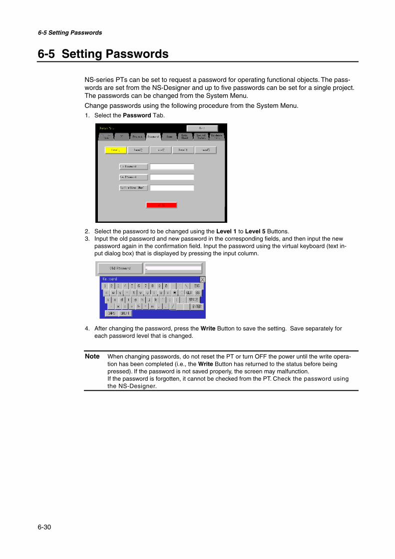
6-5 Setting Passwords
6-30
6-5 Setting Passwords
NS-series PTs can be set to request a password for operating functional objects. The pass-words are set from the NS-Designer and up to five passwords can be set for a single project.The passwords can be changed from the System Menu.
Change passwords using the following procedure from the System Menu.1. Select the Password Tab.
2. Select the password to be changed using the Level 1 to Level 5 Buttons.3. Input the old password and new password in the corresponding fields, and then input the new
password again in the confirmation field. Input the password using the virtual keyboard (text in-put dialog box) that is displayed by pressing the input column.
4. After changing the password, press the Write Button to save the setting. Save separately foreach password level that is changed.
Note When changing passwords, do not reset the PT or turn OFF the power until the write opera-tion has been completed (i.e., the Write Button has returned to the status before beingpressed). If the password is not saved properly, the screen may malfunction.If the password is forgotten, it cannot be checked from the PT. Check the password usingthe NS-Designer.

6-6 Communications Settings
6-31
6-6 Communications Settings
The methods for setting the communications conditions with the host are described here.
6-6-1 Communications ConditionsSet the communications conditions by using operations from the Comm Tab Page in theSystem Menu, as follows:
After inputting the communications conditions, press the Write Button to save the settings.
Changed settings are enabled after the PT is restarted.
@ Communications Conditions Setting Items
The setting items for the communications conditions between the PT and host are as follows:
• Communications Auto-return
Select whether or not to use communications auto-return using the ON and OFF Buttons.
ON: The PT will automatically return to RUN mode when a communications error oc-curs, without displaying an error message dialog box.
OFF: The PT will stop running when a communications error occurs and an error mes-sage dialog box will be displayed. Press the OK Button in the error messagedialog box to return to RUN mode. The default setting is OFF.
• Time-out Interval
Set the time before a timeout error occurs when a response is not received from the host.The timeout interval can be set to between 1 and 10 (unit: s). Input the value by using thetenkey or the Up ( ) and Down ( ) buttons that are displayed by pressing the display area.
The default setting is 3 s.
Note Set the time-out interval to 3 s min. when using 1:N NT Links. If the time-out interval is lessthan 3 s, abnormal communications may occur.

6-6 Communications Settings
6-32
• Retry Counts
Set the number of retries for communications before an error screen will be displayed, whena communications error occurs while communicating with the host. If communications are un-successful after the number of communications retries specified here have been executed,processing set for the communications auto return will be executed. The number of retriescan be set to between 0 and 255 times. Input the value by using the tenkey or the Up ( )and Down ( ) buttons that are displayed by pressing the display area.
The default setting is 5 retries.
Note Set the retry counts to 5 retries min. when using 1:N NT Links. If less than 5 retries is set, ab-normal communications may occur.
• Port Communications Method and Communications TypeSet the communications method for serial ports A and B, for Ethernet and for Controller Link. Theright half of the screen will change according to the settings.
Reference• To change the communications method for another port, the Write Button must be pressed before
continuing. The settings will not be saved if the communications method is switched withoutpressing the Write Button.
• For details on Temperature Controller and Memory Link setting methods and other procedures,refer to the NS Series Host Connection Manual (V085).
• For details on Host Link setting methods and other procedures, refer to the NS Series Host Con-nection Manual (Host Link).
@ Supported Communications Method Combinations
It is not possible to connect to a PLC via NT Link (1:N) with both serial ports A and B at thesame time. It is not possible to use a Bar Code Reader with both serial ports A and B at thesame time. It is also not possible to use a modem with both serial ports A and B at the sametime.
Serial ports A and B, Ethernet and Controller Link can be used in any combination with othercommunications methods.
Serial ports A and B, Ethernet and Controller Link, however, cannot be all used simultane-ously (except when using a Bar Code Reader).
Reference Serial ports A and B, Ethernet and Controller Link can be set to be used simultaneously,but proper operations cannot be guaranteed (except when using a Bar Code Reader).Therefore, do not set all the ports to be used simultaneously.
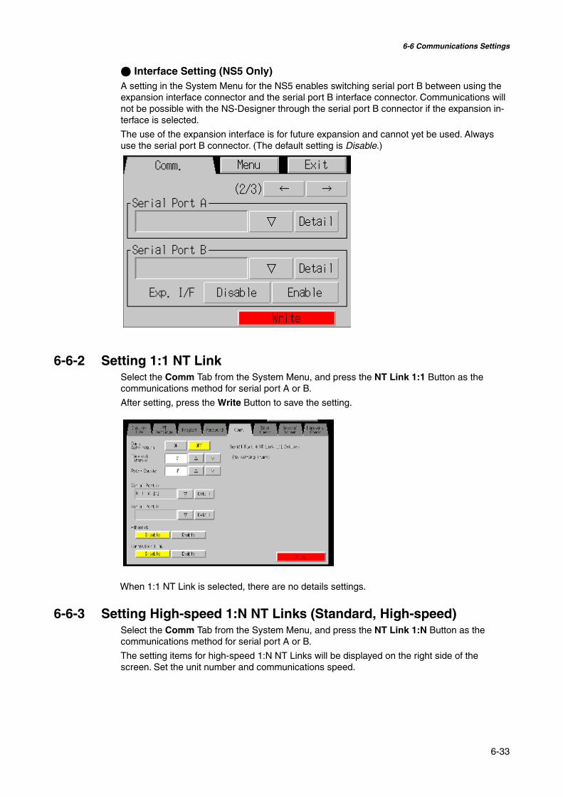
6-6 Communications Settings
6-33
@ Interface Setting (NS5 Only)A setting in the System Menu for the NS5 enables switching serial port B between using theexpansion interface connector and the serial port B interface connector. Communications willnot be possible with the NS-Designer through the serial port B connector if the expansion in-terface is selected.
The use of the expansion interface is for future expansion and cannot yet be used. Alwaysuse the serial port B connector. (The default setting is Disable.)
6-6-2 Setting 1:1 NT LinkSelect the Comm Tab from the System Menu, and press the NT Link 1:1 Button as thecommunications method for serial port A or B.
After setting, press the Write Button to save the setting.
When 1:1 NT Link is selected, there are no details settings.
6-6-3 Setting High-speed 1:N NT Links (Standard, High-speed)Select the Comm Tab from the System Menu, and press the NT Link 1:N Button as thecommunications method for serial port A or B.
The setting items for high-speed 1:N NT Links will be displayed on the right side of thescreen. Set the unit number and communications speed.

6-6 Communications Settings
6-34
After setting, press the Write Button.
• Communications Conditions for 1:N NT Links
Setting item Function SettingsUnit number Sets the unit number. 0 to 7Communications Speed Sets the baud Communications speed. Standard, high-speed
Reference The unit numbers that can be set depend on the type of host used, as follows:
• C200HE(-Z):Unit numbers 0 to 3 (up to four PTs for each port of the host)
• C200HG(-Z), C200HX(-Z), CS1G/H, CS1G/H-H, CQM1H, CJ1G, and CJ1G/H-H:Unit numbers 0 to 7 (up to eight PTs for each port of the host)
Refer to 4-2 1:N Connection to the Host for the host settings.
6-6-4 Setting EthernetTo use Ethernet, select the Comm Tab from the System Menu and press the Enable Button.
The setting items for Ethernet will be displayed on the right side of the screen. Display andset the network address, node address, IP address, subnet mask, and default gateway. Dis-play the MAC address and IP address table display.
After setting, press the Write Button.
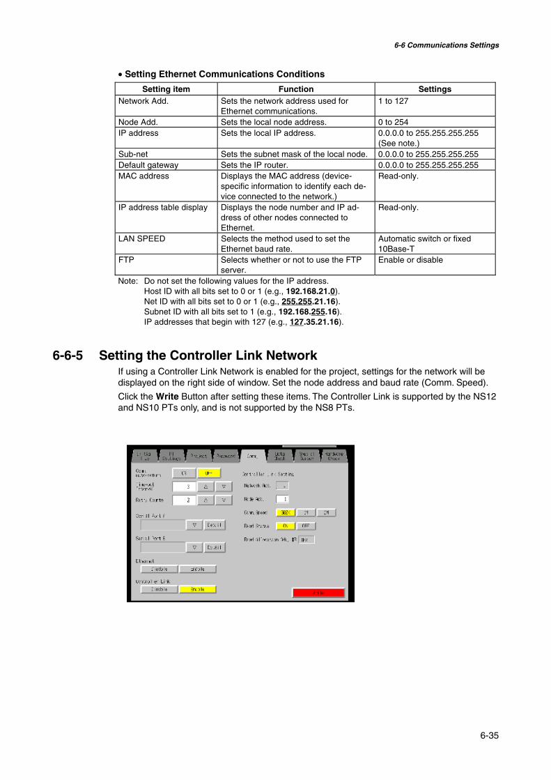
6-6 Communications Settings
6-35
• Setting Ethernet Communications Conditions
Setting item Function SettingsNetwork Add. Sets the network address used for
Ethernet communications.1 to 127
Node Add. Sets the local node address. 0 to 254IP address Sets the local IP address. 0.0.0.0 to 255.255.255.255
(See note.)Sub-net Sets the subnet mask of the local node. 0.0.0.0 to 255.255.255.255Default gateway Sets the IP router. 0.0.0.0 to 255.255.255.255MAC address Displays the MAC address (device-
specific information to identify each de-vice connected to the network.)
Read-only.
IP address table display Displays the node number and IP ad-dress of other nodes connected toEthernet.
Read-only.
LAN SPEED Selects the method used to set theEthernet baud rate.
Automatic switch or fixed10Base-T
FTP Selects whether or not to use the FTPserver.
Enable or disable
Note: Do not set the following values for the IP address.Host ID with all bits set to 0 or 1 (e.g., 192.168.21.0).Net ID with all bits set to 0 or 1 (e.g., 255.255.21.16).Subnet ID with all bits set to 1 (e.g., 192.168.255.16).IP addresses that begin with 127 (e.g., 127.35.21.16).
6-6-5 Setting the Controller Link NetworkIf using a Controller Link Network is enabled for the project, settings for the network will bedisplayed on the right side of window. Set the node address and baud rate (Comm. Speed).
Click the Write Button after setting these items. The Controller Link is supported by the NS12and NS10 PTs only, and is not supported by the NS8 PTs.

6-6 Communications Settings
6-36
• Setting Communications Conditions for the Controller Link Network
Item Function SettingNetwork Add. Displays the network address
used for Controller Link.Display only
Node Address Sets the local node address. 1 to 32Comm. Speed Sets the baud rate. 500K, 1M, or 2MRead Status Displays whether Controller Link status is read (display
only).Read AllocationAdd.
Displays address where status is read (display only).
Note: Using the Controller Link network and the network number cannot be changed at the PT. If youchange the setting, select System Setting on NS-Designer, change the setting, and thentransfer the project to the PT.
6-6-6 Setting Bar Code ReadersThe PT has a Bar Code Reader input function allowing input of barcode data as characterstrings in the String Display & Input object.
The methods for setting the communications conditions with the Bar Code Reader are de-scribed here.
Reference • Refer to 3-4 Connecting to Bar Code Readers for information on methods for con-necting Bar Code Readers.
• The Bar Code Reader can be connected to either serial port A or serial port B only.
Set the communications conditions and confirmation method for the Bar Code Reader usingthe following procedure from the System Menu.
Set the Bar Code Reader’s communications method for serial port A or serial port B.The setting items for the Bar Code Reader will be displayed on the right side of the screen. Setthe Communications speed, data bits, stop bits, parity, and input method.After setting, press the Write Button to save the settings.

6-6 Communications Settings
6-37
• Setting Communications Conditions for Bar Code Reader Mode
Setting item Function SettingsComm. speed Sets the communications speed for
communications with the Bar CodeReader.
4800, 9600, or 19200 (bps)
Data bits Sets the data bit length. 7 or 8 bitsStop bits Sets the data stop bit length. 1 or 2 bitsParity Sets the data parity bits. None, odd, or evenInput method Sets the confirmation method used after
inputting data in the input column.Auto or manual confirmation
Continuous input Sets continuous barcode input to Yes orNo.
Yes or No
6-6-7 Modem SettingsData can be transferred from a personal computer to the PT through a modem. The methodused to set the data transfer conditions for the modem is described here.
Reference • Refer to 10-1 PT Transferring Data to the PT in the NS-Designer Operation Manual fordetails on modem types and connections.
• The modem can be connected to either Serial Port A or Serial Port B, but not to bothat the same time.
Set the communications conditions for the modem from the System Menu using the followingprocedure.
1. Set the communications method for serial port A or serial port B to the modem, and pressthe Detail Button
2. The settings for the modem will be displayed on the right side of the screen. Set thecommunications speed. After the setting is entered, press the Write Button to save it.
• Setting Communications Conditions for Modem Data Transfers
Setting item Function SettingsComm. Speed Sets the communications speed. 9600, 19200, 38400, 57600,
or 115200 (bps)
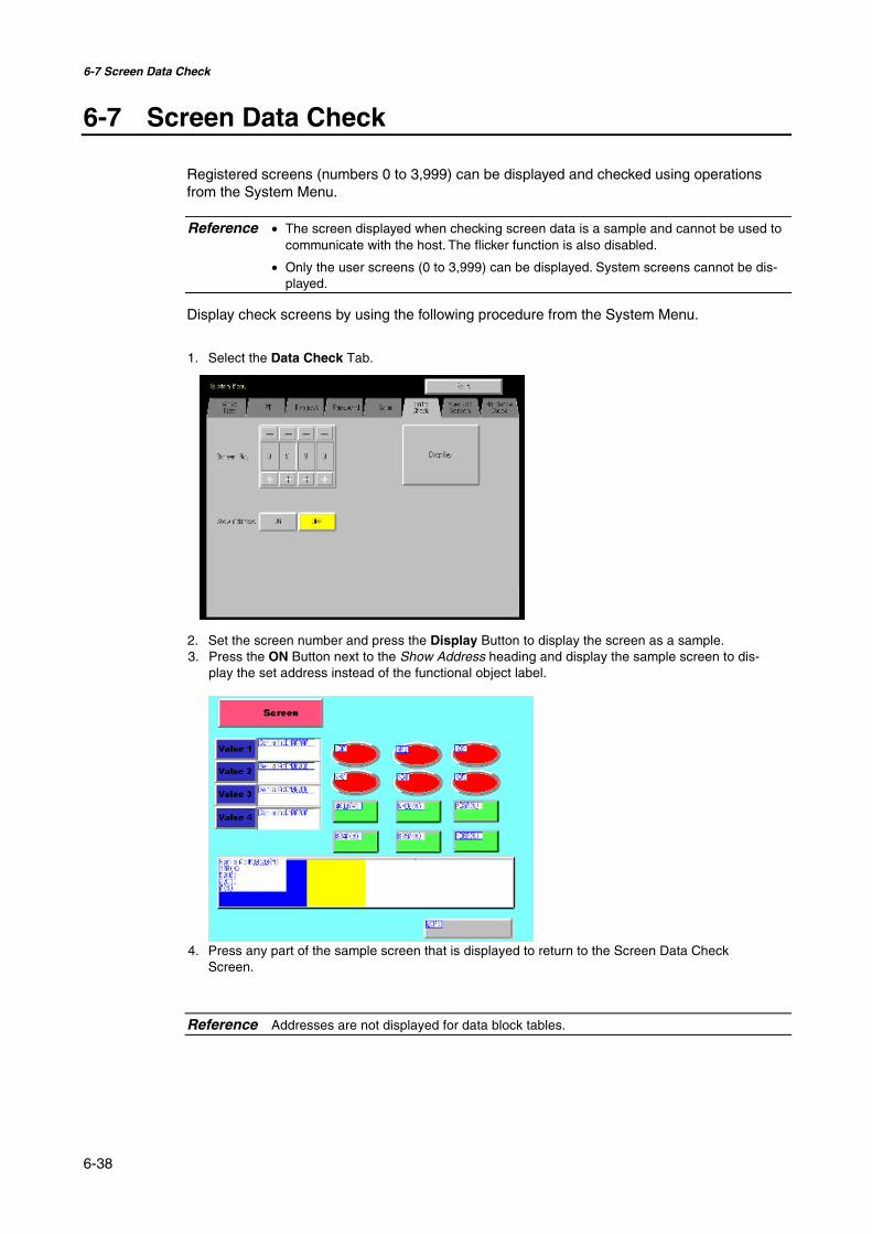
6-7 Screen Data Check
6-38
6-7 Screen Data Check
Registered screens (numbers 0 to 3,999) can be displayed and checked using operationsfrom the System Menu.
Reference • The screen displayed when checking screen data is a sample and cannot be used tocommunicate with the host. The flicker function is also disabled.
• Only the user screens (0 to 3,999) can be displayed. System screens cannot be dis-played.
Display check screens by using the following procedure from the System Menu.
1. Select the Data Check Tab.
2. Set the screen number and press the Display Button to display the screen as a sample.3. Press the ON Button next to the Show Address heading and display the sample screen to dis-
play the set address instead of the functional object label.
4. Press any part of the sample screen that is displayed to return to the Screen Data CheckScreen.
Reference Addresses are not displayed for data block tables.
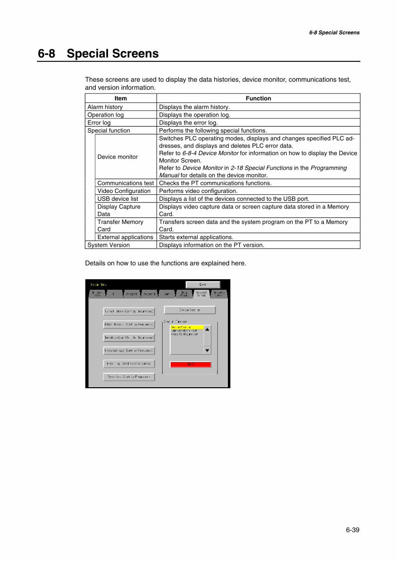
6-8 Special Screens
6-39
6-8 Special Screens
These screens are used to display the data histories, device monitor, communications test,and version information.
Item FunctionAlarm history Displays the alarm history.Operation log Displays the operation log.Error log Displays the error log.Special function Performs the following special functions.
Device monitor
Switches PLC operating modes, displays and changes specified PLC ad-dresses, and displays and deletes PLC error data.Refer to 6-8-4 Device Monitor for information on how to display the DeviceMonitor Screen.Refer to Device Monitor in 2-18 Special Functions in the ProgrammingManual for details on the device monitor.
Communications test Checks the PT communications functions.Video Configuration Performs video configuration.USB device list Displays a list of the devices connected to the USB port.Display CaptureData
Displays video capture data or screen capture data stored in a MemoryCard.
Transfer MemoryCard
Transfers screen data and the system program on the PT to a MemoryCard.
External applications Starts external applications.System Version Displays information on the PT version.
Details on how to use the functions are explained here.
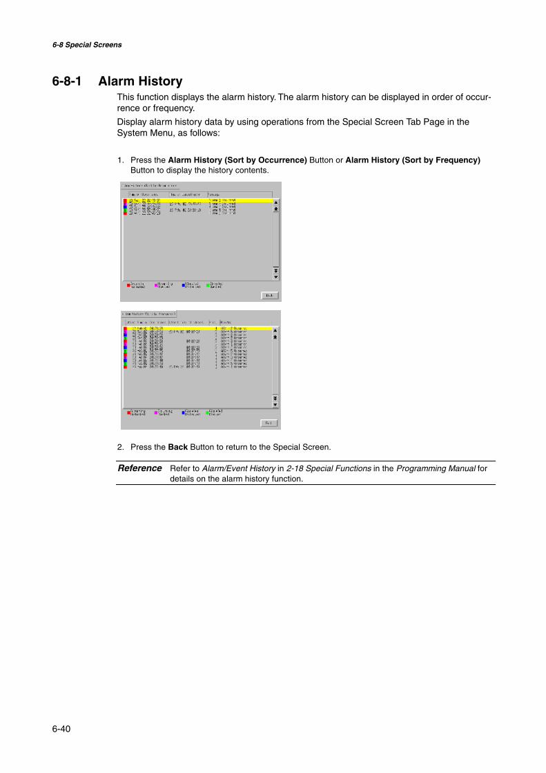
6-8 Special Screens
6-40
6-8-1 Alarm HistoryThis function displays the alarm history. The alarm history can be displayed in order of occur-rence or frequency.
Display alarm history data by using operations from the Special Screen Tab Page in theSystem Menu, as follows:
1. Press the Alarm History (Sort by Occurrence) Button or Alarm History (Sort by Frequency)Button to display the history contents.
2. Press the Back Button to return to the Special Screen.
Reference Refer to Alarm/Event History in 2-18 Special Functions in the Programming Manual fordetails on the alarm history function.

6-8 Special Screens
6-41
6-8-2 Operation LogThis function displays the operation log. The operation log can be displayed in order of occur-rence or frequency.
Display operation log data by using operations from the Special Screen Tab Page in theSystem Menu, as follows:
1. Press the Operation Log (Sort by Occurrence) Button or Operation Log (Sort by Frequency)Button to display the operation log contents.
2. Press the Back Button to return to the Special Screen.
Reference Refer to 6-2-4 Operation Log Initialization in this manual and Operation Log in 2-18Special Functions in the Programming Manual for details on the operation log.

6-8 Special Screens
6-42
6-8-3 Error LogThis function displays the macro error history. Macro errors can be displayed in order of oc-currence or frequency.
Display error log data by using operations from the Special Screen Tab Page in the SystemMenu, as follows:
1. Press the Error Log (Sort by Occurrence) Button or Error Log (Sort by Frequency) Button todisplay the error log contents.
2. Press the Back Button to return to the Special Screen.
Reference Refer to 6-2-5 Error Log Initialization in this manual and Error Log in 2-18 SpecialFunctions in the Programming Manual for details on the error log.

6-8 Special Screens
6-43
6-8-4 Device MonitorThe device monitor is an expansion function of the PT. This function is supported by CPM1A,CPM2A, CPM2C, CQM1, CQM1H, C200HS, C200HX/HG/HE(-Z), CS1G/CS1H, CS1D,CS1G/CS1H-H, CJ1G, and CJ1M PLCs.
The device monitor has the following functions.
• Switches the PLC operating modes.
• Displays, changes, and performs force-sets/resets of current values in specified addresses(registered monitor).
• Displays a list of the current values (continuous monitor) in consecutive addresses (DM,EM, and WR Area words).
• Displays PLC error information (error logs) and deletes the errors (error information).
Details on methods of opening the Device Monitor Screen are explained here. Refer to De-vice Monitor in 2-18 Special Functions in the Programming Manual for details on the functionand operation methods.
Note Always check carefully that the system is safe before performing the following operations us-ing the device monitor.• Changing the monitor data and timer/counter current values.• Switching operating modes.• Performing force-sets/resets• Changing timer/counter set values.

6-8 Special Screens
6-44
The Device Monitor Screen is displayed by using operations from the Special Screen TabPage from the System Menu, as follows:
1. Select Device Monitor from the Special Functions List Box, and press the START Button.
2. The Device Monitor Screen will be displayed.
3. Press the Quit Button to return to the Special Screen.

6-8 Special Screens
6-45
6-8-5 Communication TestThis function checks whether communications are enabled, by performing simple communi-cations.
Display the Communication Test Screen by using operations from the Special Screen TabPage in the System Menu, as follows:
4. Select Communication Test from the Special Functions List Box, and press the START Button.
5. Press the Communication Test Button to switch to the Communications Test Screen.
6. Set each of the setting items, as follows:

6-8 Special Screens
6-46
• Setting and Display Items in Communication Test Screen
Item DetailsSend to Sets the address of the transmission destination in the format (network ad-
dress).(node address).(unit number).Sets the following addresses when performing a communications test for a nodeconnected to serial port A or B.• Serial port A: 111.1.0• Serial port B: 112.1.0
Send message Sets the FINS command being to be sent.Number ofsends
Displays the number of times messages are transmitted. The number of times isfixed to 1.
Receive Time-out
Sets the time before the message timeout occurs. Displays an error messagewhen the timeout time is exceeded after transmission.The setting time is applicable for Ethernet only. For serial communications, thetimeout monitor time set from the Comm Tab is used.
7. Press the Start Button to start transmission.The sending indicator will remain lit until the transmission is completed.After transmission, the Receiving indicator will remain lit until reception is completed.
8. If communications are normal, a response will be received from the transmission destination andthe following items will be displayed. Refer to the FINS Command Reference Manual (W227) fordetails on FINS commands and information displayed in comments.
• Display Items in Communication Test Screen
Item DetailsSID (See note 1.) The SID used for transmission is displayed as a hexadecimal.
The SID is incremented between 0 and 0xFF and returns to 0 after 0xFF isexceeded.
Received header Displays the FINS header that is received. (See note 2.)Received message Displays the received message.ms Displays the time lapsed in ms from sending the FINS command until re-
ceiving the FINS response.Comment Displays the status, such as “normal completion,” according to the comple-
tion code after reception.Note 1. SID is the source process ID.
2. The FINS header is the header that precedes the FINS command.
Refer to the FINS Command Reference Manual (W227) for details on FINS commands.
9. Press the Back Button to return to the Special Screen.
6-8-6 Video ConfigurationA Video Input Unit can be mounted to the PT to display images by connecting video devices.The user can adjust the image and output signals to a Vision Sensor from this window.
This section describes only the procedure for opening the window. For details, refer to 2-18-10 Video Configuration in the NS Series Programming Manual.
The Video Configuration Window can be access by selecting the System Menu and clickingthe Special Screen Tab as shown below.

6-8 Special Screens
6-47
1. Select Video Configuration from the list under Special Function, and click the Startbutton.
The Video Configuration Window will be displayed.
2. Press the Back Button to return to the Special Window.
Reference Press the Write Button to save the adjustments to the displayed image.When starting the PT next time, the saved settings for the adjustments will be automati-cally reflected on the display.

6-8 Special Screens
6-48
6-8-7 USB Device ListThis function displays information about the devices connected to the PT’s USB port.
Item DetailsDevice list A list of the devices currently connected to the USB port is dis-
played.Driver list A list of connectable USB devices that are supported by the NS
Series is displayed.
1. Select USB Device List from the Special Functions List Box, and press the START Button.
2. The USB Device List Window will be displayed.
A list of USB devices currently connected and a list of USB devices supported by the NS Seriesare displayed. Press the Update Button to reconfirm the connected USB devices and refresh thedisplay.
3. Press the Return Button to return to the Special Screen.

6-8 Special Screens
6-49
6-8-8 Display Capture DataVideo capture data and screen capture data stored in a Memory Card can be displayed.Perform the following procedure under Special Screen Tab on the System Menu.
1. Select Display capture data from the Special Function List Box and press the STARTButton.
2. The Capture Data Display Screen will be displayed.
1
5
3
4
2
6
7
8
9
1011
No. Item Details1 Data Displays a BMP file stored in the LOG folder in the Memory Card.2 File name Display the file name and time stamp of the BMP file.3 Display Press the Display Button and then the bitmap to enlarge the display.
Press the Print Button to print the BMP file. Press the Full ScreenButton to display the BMP file in original format. The original displaydivided into four areas will return if BACK is pressed.
4 Delete The following dialog box will appear if the Delete Button and then thebitmap are pressed.
Press the Yes Button to delete the BMP. The capture display screenwill return if the No Button is pressed.

6-8 Special Screens
6-50
No. Item Details5 Back Press to return to the Special Screens Tab Page.6 Sort by name
(Ascending)Press to sort the bitmap file names alphabetically.
7 Sort by name(Descending)
Press to sort the bitmap file names reversed alphabetically.
8 From Old Date &Time
Press to sort the bitmap file names starting from the oldest one.
9 From New Date& Time
Press to sort the bitmap file names starting from the newest one
10 < Button and> Button
Press to display the next or previous page (4 files) of bitmaps.
11 << Button and>> Button
Press to display the page back or forward by 3 pages (12 files) ofbitmaps.
6-8-9 Memory Card TransfersWith a Memory Card is inserted into the PT, please perform the following procedures usingthe Special Screens Tab Page of the System Menu. You can manually transfer screen dataand system programs without manipulating the DIP switch on the PT. The Memory Card canbe used to transfer data in the following situations.
• To transfer data to or from a Memory Card already inserted to save or read data such asdata logs and captured data.
• To transfer data after replacing a Memory Card already inserted to save data such as datalogs and captured data with a Memory Card for data transfer.
• To transfer data after inserting a Memory Card to a PT without one.
Perform the following procedures as required by the application.
Transferring Data to a Memory Card in the PTNo special action is required prior to transferring data to the Memory Card.
Replacing a Memory Card in the PT with Another Memory Card Used toSave DataUse the following procedure to replace the Memory Card already in the PT with anotherMemory Card that will be used to save data. Perform the following procedure from the Initial-ize Tab Page of the System Menu. Remove the Memory Card that is currently inserted, andinsert another one.
1. Press the Remove Button next to Memory Card of the Initialize Tab Page.2. Confirm that it is safe to remove the Memory Card, and remove it from the PT.3. Insert the Memory Card that will be used to save data into the PT.
Inserting a Memory Card into a PT without OneInsert the Memory Card into the PT.
Transferring Memory Card DataUse the following procedure from the Special Screen Tab Page of the System Menu to trans-fer data to Memory Card. Press the EXIT Button at the top left of the Memory Card Transferscreen to reset the PT.
1. Select Memory Card Transfer from the Special Functions list, and press the Start But-ton.
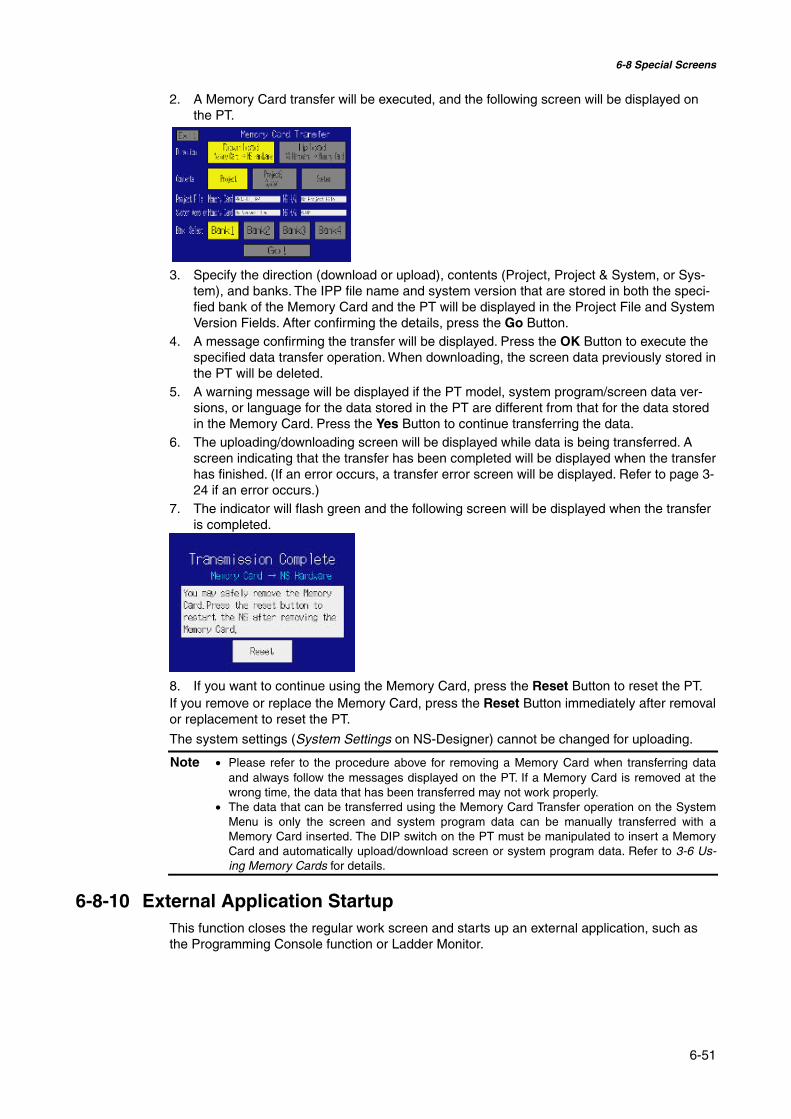
6-8 Special Screens
6-51
2. A Memory Card transfer will be executed, and the following screen will be displayed onthe PT.
3. Specify the direction (download or upload), contents (Project, Project & System, or Sys-tem), and banks. The IPP file name and system version that are stored in both the speci-fied bank of the Memory Card and the PT will be displayed in the Project File and SystemVersion Fields. After confirming the details, press the Go Button.
4. A message confirming the transfer will be displayed. Press the OK Button to execute thespecified data transfer operation. When downloading, the screen data previously stored inthe PT will be deleted.
5. A warning message will be displayed if the PT model, system program/screen data ver-sions, or language for the data stored in the PT are different from that for the data storedin the Memory Card. Press the Yes Button to continue transferring the data.
6. The uploading/downloading screen will be displayed while data is being transferred. Ascreen indicating that the transfer has been completed will be displayed when the transferhas finished. (If an error occurs, a transfer error screen will be displayed. Refer to page 3-24 if an error occurs.)
7. The indicator will flash green and the following screen will be displayed when the transferis completed.
8. If you want to continue using the Memory Card, press the Reset Button to reset the PT.If you remove or replace the Memory Card, press the Reset Button immediately after removalor replacement to reset the PT.
The system settings (System Settings on NS-Designer) cannot be changed for uploading.
Note • Please refer to the procedure above for removing a Memory Card when transferring dataand always follow the messages displayed on the PT. If a Memory Card is removed at thewrong time, the data that has been transferred may not work properly.
• The data that can be transferred using the Memory Card Transfer operation on the SystemMenu is only the screen and system program data can be manually transferred with aMemory Card inserted. The DIP switch on the PT must be manipulated to insert a MemoryCard and automatically upload/download screen or system program data. Refer to 3-6 Us-ing Memory Cards for details.
6-8-10 External Application StartupThis function closes the regular work screen and starts up an external application, such asthe Programming Console function or Ladder Monitor.

6-8 Special Screens
6-52
The following describes the procedure for starting up external applications. Refer to the indi-vidual manual for more details on functions and operations applicable to the application. Referto 2-18-11 Programming Console Function in the NS-Series PT Programming Manual formore details.
Start up an external application by using operations from the Special Screen Tab in theSystem Menu as follows:
1. Select an external application from the Special Functions List Box, and press the START button.The following diagram shows the screen with Ladder Monitor selected.
2. The NS-series PT resets.3. The NS-series PT reboots, and the selected application starts up.
If an application displays a message, refer to its manual.
Reference Device monitor, Communication Test, Video Configuration, USB Device List, andDisplay Capture Data are not external applications. The screen in the System Menuswitches when you press the START button with one of these selected, but the NS-series PT does not reset.
6-8-11 Version DisplayThis function displays information on the PT version.
Display the Version Display Screen by using operations from the Special Screen Tab Pagein the System Menu, as follows:
1. Press the System Version Button to switch to the Version Display Screen.2. The product model and version will be displayed.
3. Press the Back Button to return to the Special Screen.

6-9 Hardware Check
6-53
6-9 Hardware Check
The hardware check is used to check the following functions.
Item FunctionLCD check Checks the LCD.Touch switch check Checks touch panel input.
6-9-1 LCD CheckThis function checks whether the LCD (screen display) is operating normally.
Check the LCD by using operations from the Hardware Check Tab Page in the System Menu,as follows:
1. Press the LCD Check Button to switch to the LCD Check Screen.
2. Press the Back Button to return to the Hardware Check Screen.

6-9 Hardware Check
6-54
6-9-2 Touch Switch CheckThis function checks whether the touch switches are operating normally.
Check the touch panel by using operations from the Hardware Check Tab Page in the SystemMenu, as follows:
1. Press the Touch Switch Check Button to switch to the Touch Switch Check Screen.
2. Press the screen. If the part of the screen touched is shown in inverse display, the touch switchis operating normally.
The position touchedis shown in inversedisplay.
3. Press the button in the top right corner to return to the Hardware Check Screen.
Reference Two points cannot be touched at the same time on the Touch Panel Check Screen.

6-10 Starting Operations
6-55
6-10 Starting Operations
The host and PT connected to it start operating after the project data has finished beingtransferred and the System Menu settings (communications conditions with the host, etc.)have been completed.
Note Start actual operation only after sufficiently checking the operation of the screen data andhost programming.
@ Switching to RUN Mode and Starting UpPressing the Exit Button at the top right of the screen in the System Menu will display thescreen that was displayed before moving to the System Menu, change the status to RUNmode, and start running the PT. The pop-up screens that were open before switching to theSystem Menu, however, will not be displayed.
Reference The error message indicating a project read error will be displayed if the System Menuis closed while screen data is being initialized. Always transfer the screen data from theNS-Designer or Memory Card after initializing screen data.
@ Checking Communications with the HostExecute the host program and check that the following operations are normal.
• Check that the PT screens will switch according to the host program.If the screen displays cannot be switched normally, check whether the PT and host areconnected properly, and whether the hardware settings are correct. For details, refer toSection 4 Connecting the Host to the Serial Port or Section 5 Connecting to Host viaEthernet or Controller Link.
• Use the Support Software (CX-Programmer, etc.) to display the details on words and bits tocheck that the results of PT button operations and numerical/character string input opera-tions have been properly transmitted to the host.
• If the operation results are not transmitted to the host properly, check the object settings.Refer to the object descriptions in the PT Programming Manual for details on object set-tings.

6-10 Starting Operations
6-56
@ Communications Not Established with HostUse the following procedure to check communications if the PT and host are not communi-cating normally.
Note The whole system may stop, depending on the method used to turn the power ON and OFF.Always follow the specified procedure when turning the power ON or OFF.
Check cables
Check connections host to PT
Check functional objectaddresses
Check the addresses and host names set for functional objects. Besure that all address settings are within range.
Check the connections between the PT and the host. Refer to Section 4Connecting to the Host with Serial Port and Section 5 Connecting to Host viaEthernet or Controller Link.
Check PT settings
Check the cable models and cable pins.
Refer to Appendix 5 Preparing Connecting Cables.
Check the communications settings under the System Menu.Refer to 6-6 Communications Settings.
Check the host settings using the CX-Programmer or other ProgrammingDevice. Refer to Section 4 Connecting to Host with Serial Port and Section 5Connecting to Host via Ethernet or Controller Link.
Check host settings
Section 7
Maintenance and TroubleshootingThis section describes the maintenance and inspection methods for preventing errors occurring,and troubleshooting measures when errors occur in the PT.
7-1 Maintenance ...................................................................................................................... 7-2
7-1-1 Replacing the Battery ............................................................................................... 7-27-2 Inspection and Cleaning .................................................................................................... 7-4
7-3 Troubleshooting and Maintenance .................................................................................... 7-6
7-4 Requesting a Replacement PT ......................................................................................... 7-13
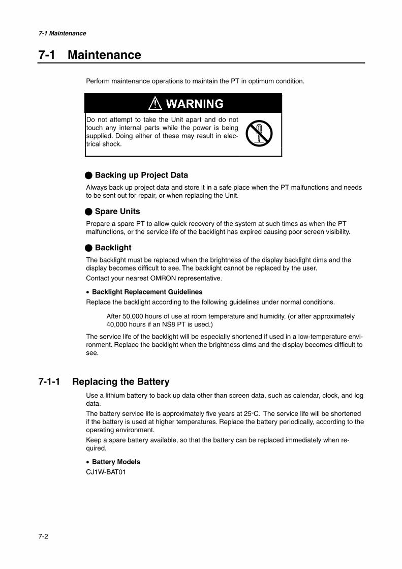
7-1 Maintenance
7-2
7-1 Maintenance
Perform maintenance operations to maintain the PT in optimum condition.
Do not attempt to take the Unit apart and do nottouch any internal parts while the power is beingsupplied. Doing either of these may result in elec-trical shock.
@ Backing up Project DataAlways back up project data and store it in a safe place when the PT malfunctions and needsto be sent out for repair, or when replacing the Unit.
@ Spare UnitsPrepare a spare PT to allow quick recovery of the system at such times as when the PTmalfunctions, or the service life of the backlight has expired causing poor screen visibility.
@ BacklightThe backlight must be replaced when the brightness of the display backlight dims and thedisplay becomes difficult to see. The backlight cannot be replaced by the user.
Contact your nearest OMRON representative.
• Backlight Replacement Guidelines
Replace the backlight according to the following guidelines under normal conditions.
After 50,000 hours of use at room temperature and humidity, (or after approximately40,000 hours if an NS8 PT is used.)
The service life of the backlight will be especially shortened if used in a low-temperature envi-ronment. Replace the backlight when the brightness dims and the display becomes difficult tosee.
7-1-1 Replacing the BatteryUse a lithium battery to back up data other than screen data, such as calendar, clock, and logdata.
The battery service life is approximately five years at 25°C. The service life will be shortenedif the battery is used at higher temperatures. Replace the battery periodically, according to theoperating environment.
Keep a spare battery available, so that the battery can be replaced immediately when re-quired.
• Battery Models
CJ1W-BAT01
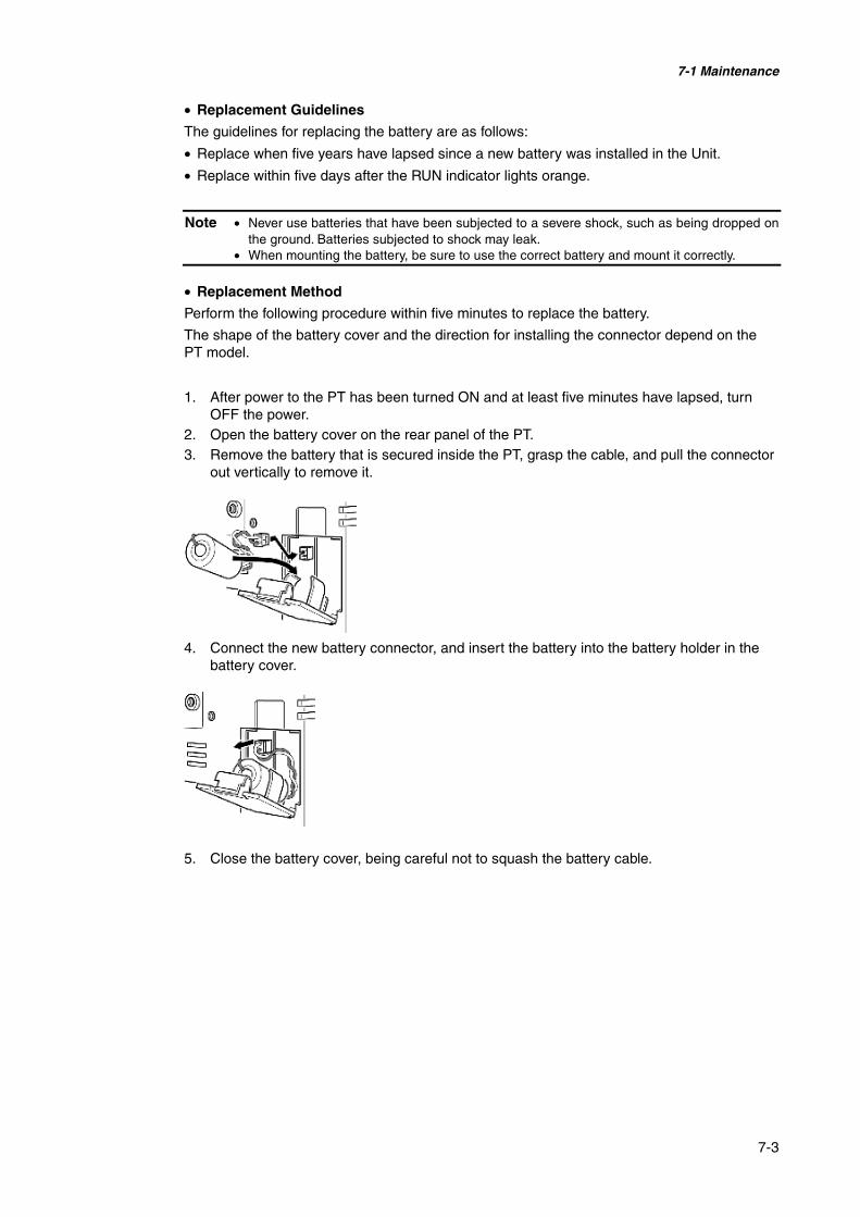
7-1 Maintenance
7-3
• Replacement Guidelines
The guidelines for replacing the battery are as follows:
• Replace when five years have lapsed since a new battery was installed in the Unit.
• Replace within five days after the RUN indicator lights orange.
Note • Never use batteries that have been subjected to a severe shock, such as being dropped onthe ground. Batteries subjected to shock may leak.
• When mounting the battery, be sure to use the correct battery and mount it correctly.
• Replacement Method
Perform the following procedure within five minutes to replace the battery.
The shape of the battery cover and the direction for installing the connector depend on thePT model.
1. After power to the PT has been turned ON and at least five minutes have lapsed, turnOFF the power.
2. Open the battery cover on the rear panel of the PT.3. Remove the battery that is secured inside the PT, grasp the cable, and pull the connector
out vertically to remove it.
4. Connect the new battery connector, and insert the battery into the battery holder in thebattery cover.
5. Close the battery cover, being careful not to squash the battery cable.
7-2 Inspection and Cleaning
7-4
7-2 Inspection and Cleaning
Clean and inspect the PT periodically to maintain it in optimum condition for use.
@ Cleaning MethodsThe screen visibility will be impaired if the display becomes dirty. Clean the display periodi-cally using the following methods:
• For daily cleaning, wipe with a soft, dry cloth. Attempting to remove heavy dirt with thecloth may scratch the front panel sheet. Use a damp cloth and wipe the surface again toremove dirt.
• If dirt cannot be removed using a dry cloth, dampen the cloth sufficiently with a neutralcleaning agent solution (approximately 2%), squeeze the cloth out, and then wipe the sur-face.
• Materials such as rubber, vinyl, or tape that are attached to the Unit will leave stains if leftfor a long time. If such material is attached to the Unit, remove when cleaning.
Note Never use benzene, thinner, or other volatile solvents, or chemical cloths to clean the PT.
@ Inspection MethodsInspect the PT once every six to twelve months. Shorten the interval between inspectionswhen using the PT in extreme conditions, such as under high temperatures, high humidity, orenvironments subject to large quantities of dust.

7-2 Inspection and Cleaning
7-5
• Inspection Items
Inspect the PT for the following items to check whether the PT is operating within the speci-fied criteria. If the PT is outside the criteria, use measures such as improving the operatingenvironment to conform to the standards, or tightening screws.
Inspectionitems
Inspection details Criteria Inspection means
Powersupply
Power terminal voltage fluc-tuation
Allowable voltage range(24 VDC ±15%)
Tester
Ambient temperature (tem-perature in control panel)
0 to 50°C (Refer to Appendix 2.) Thermometer
Ambient humidity (tempera-ture in control panel)
35% to 85% (Refer to Appendix2.)
Temperature meter
Presence of dust No dust accumulated. Visual inspection
Ambientenvironment
Presence of oil No oil between front panel sheetand molding.
Visual inspection
Looseness of fixed mountingbracket
Specified torque. Phillips screwdriver
Connection status of Con-necting Cable Connectors
Fully inserted, locked, and withNo looseness.
Phillips screwdriver
Looseness of external wiringscrews
No looseness. Phillips screwdriver
Mountingconditions
Status of external connectingcables
No breaks or other damage Visual inspection,tester
Backlight brightness Sufficient brightness.Backlight life (at room tempera-ture of 25°C) is 50,000 hours, asa guideline.
Visual inspectionParts withlimitedservice life
Battery 5 years (at room temperature of25°C).
Replace every 5years
Note • Do not disassemble, repair, or modify the PT.• Follow all local government regulations, where applicable, when disposing of the Unit and
used batteries.
7-3 Troubleshooting and Maintenance
7-6
7-3 Troubleshooting and Maintenance
When an error occurs while operating the PT, search for the symptom in the following tableand take measures according to those provided.
Errors during Data Transfer
Symptoms atPT
Causes Measures
The NS-Designer isnot connected tothe PT.
Check the wiring conditions of the connecting cable.(Refer to 3-3 Connecting the NS-Designer.)
Serial transfernot possiblebetween NS-Designer andPT.
The Expansion Inter-face for serial port B isset to the expansioninterface (NS5 only).
Set the Expansion Interface to Disable on the Comm Tab Pagefrom the NS5 System Menu.
Errors during PT Startup
Symptoms atPT
Causes Measures
Power is not beingsupplied to the PT.
Check the connection points and supply power to the PTcorrectly.(Refer to 3-1 Installing the PT.)
The fuse is broken. The PT needs repair. Contact your nearest OMRON repre-sentative.
Indicators donot light.
The system pro-gram is corrupted(fatal error).
The PT may be faulty. Contact your nearest OMRON repre-sentative.
The indicatoris lit orangeand the screenis blank.
The system pro-gram is corrupted(fatal error).
The PT may be faulty. Contact your nearest OMRON repre-sentative.
The indicatoris lit green andthe screen isblank.
The system pro-gram is corrupted(non-fatal error).
Reinstall the system program. (Refer to 3-6 Using MemoryCards.)Contact your nearest OMRON representative if the sameproblem occurs after reinstalling the system program.
The indicatoris flashinggreen and thebuzzer re-peatedly turnsON and OFF.
The backlight hasmalfunctioned.
The backlight must be replaced. Contact your nearest OM-RON representative.
The screen isblank and theindicator isflashing green.
Automatic up-load/download hasended normally.
This is not an error. Turn OFF all the DIP switch pins andturn ON the power to the PT again.
The screen isblank and theindicator isflashing red.
Automatic up-load/download hasended abnormally.
The system program may be corrupted. Reinstall the sys-tem program.(Refer to 3-6 Using Memory Cards.)If the same problem occurs after reinstalling the systemprogram, the PT may be faulty. Contact your nearest OM-RON representative.An attempt may have been made to transfer screens thatare larger than the memory of the PT. Check the screendata at the transfer destination.
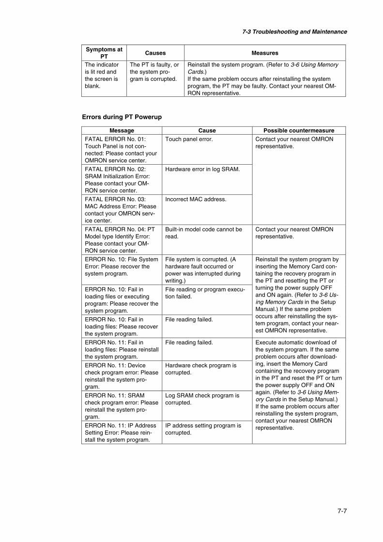
7-3 Troubleshooting and Maintenance
7-7
Symptoms atPT
Causes Measures
The indicatoris lit red andthe screen isblank.
The PT is faulty, orthe system pro-gram is corrupted.
Reinstall the system program. (Refer to 3-6 Using MemoryCards.)If the same problem occurs after reinstalling the systemprogram, the PT may be faulty. Contact your nearest OM-RON representative.
Errors during PT Powerup
Message Cause Possible countermeasureFATAL ERROR No. 01:Touch Panel is not con-nected: Please contact yourOMRON service center.
Touch panel error.
FATAL ERROR No. 02:SRAM Initialization Error:Please contact your OM-RON service center.
Hardware error in log SRAM.
FATAL ERROR No. 03:MAC Address Error: Pleasecontact your OMRON serv-ice center.
Incorrect MAC address.
Contact your nearest OMRONrepresentative.
FATAL ERROR No. 04: PTModel type Identify Error:Please contact your OM-RON service center.
Built-in model code cannot beread.
Contact your nearest OMRONrepresentative.
ERROR No. 10: File SystemError: Please recover thesystem program.
File system is corrupted. (Ahardware fault occurred orpower was interrupted duringwriting.)
ERROR No. 10: Fail inloading files or executingprogram: Please recover thesystem program.
File reading or program execu-tion failed.
ERROR No. 10: Fail inloading files: Please recoverthe system program.
File reading failed.
Reinstall the system program byinserting the Memory Card con-taining the recovery program inthe PT and resetting the PT orturning the power supply OFFand ON again. (Refer to 3-6 Us-ing Memory Cards in the SetupManual.) If the same problemoccurs after reinstalling the sys-tem program, contact your near-est OMRON representative.
ERROR No. 11: Fail inloading files: Please reinstallthe system program.
File reading failed.
ERROR No. 11: Devicecheck program error: Pleasereinstall the system pro-gram.
Hardware check program iscorrupted.
ERROR No. 11: SRAMcheck program error: Pleasereinstall the system pro-gram.
Log SRAM check program iscorrupted.
ERROR No. 11: IP AddressSetting Error: Please rein-stall the system program.
IP address setting program iscorrupted.
Execute automatic download ofthe system program. If the sameproblem occurs after download-ing, insert the Memory Cardcontaining the recovery programin the PT and reset the PT or turnthe power supply OFF and ONagain. (Refer to 3-6 Using Mem-ory Cards in the Setup Manual.)If the same problem occurs afterreinstalling the system program,contact your nearest OMRONrepresentative.
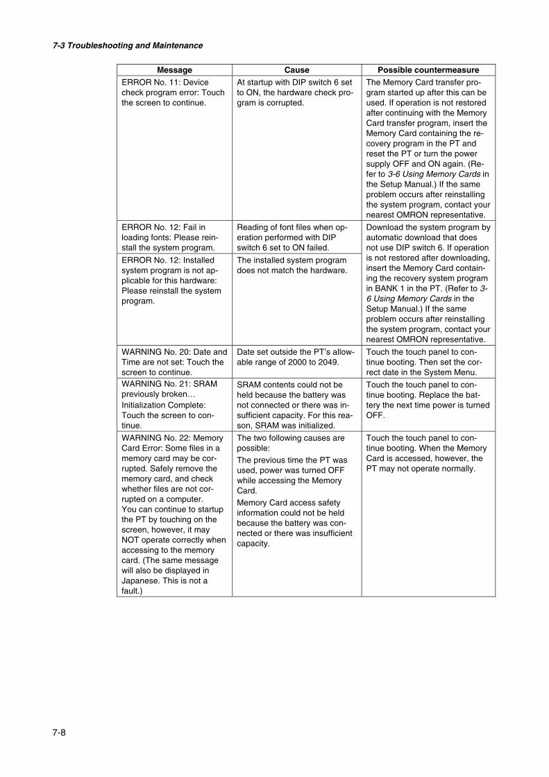
7-3 Troubleshooting and Maintenance
7-8
Message Cause Possible countermeasureERROR No. 11: Devicecheck program error: Touchthe screen to continue.
At startup with DIP switch 6 setto ON, the hardware check pro-gram is corrupted.
The Memory Card transfer pro-gram started up after this can beused. If operation is not restoredafter continuing with the MemoryCard transfer program, insert theMemory Card containing the re-covery program in the PT andreset the PT or turn the powersupply OFF and ON again. (Re-fer to 3-6 Using Memory Cards inthe Setup Manual.) If the sameproblem occurs after reinstallingthe system program, contact yournearest OMRON representative.
ERROR No. 12: Fail inloading fonts: Please rein-stall the system program.
Reading of font files when op-eration performed with DIPswitch 6 set to ON failed.
ERROR No. 12: Installedsystem program is not ap-plicable for this hardware:Please reinstall the systemprogram.
The installed system programdoes not match the hardware.
Download the system program byautomatic download that doesnot use DIP switch 6. If operationis not restored after downloading,insert the Memory Card contain-ing the recovery system programin BANK 1 in the PT. (Refer to 3-6 Using Memory Cards in theSetup Manual.) If the sameproblem occurs after reinstallingthe system program, contact yournearest OMRON representative.
WARNING No. 20: Date andTime are not set: Touch thescreen to continue.
Date set outside the PT’s allow-able range of 2000 to 2049.
Touch the touch panel to con-tinue booting. Then set the cor-rect date in the System Menu.
WARNING No. 21: SRAMpreviously broken…Initialization Complete:Touch the screen to con-tinue.
SRAM contents could not beheld because the battery wasnot connected or there was in-sufficient capacity. For this rea-son, SRAM was initialized.
Touch the touch panel to con-tinue booting. Replace the bat-tery the next time power is turnedOFF.
WARNING No. 22: MemoryCard Error: Some files in amemory card may be cor-rupted. Safely remove thememory card, and checkwhether files are not cor-rupted on a computer.You can continue to startupthe PT by touching on thescreen, however, it mayNOT operate correctly whenaccessing to the memorycard. (The same messagewill also be displayed inJapanese. This is not afault.)
The two following causes arepossible:The previous time the PT wasused, power was turned OFFwhile accessing the MemoryCard.Memory Card access safetyinformation could not be heldbecause the battery was con-nected or there was insufficientcapacity.
Touch the touch panel to con-tinue booting. When the MemoryCard is accessed, however, thePT may not operate normally.

7-3 Troubleshooting and Maintenance
7-9
Message Cause Possible countermeasureWARNING No. 23: Screendata file(s) is not correct:Touch the screen to con-tinue and transfer screendata again.
The PT screen data is cor-rupted. (The cable was discon-nected or the power was turnedOFF during screen data trans-fer).
Touch the PT’s touch panel, andafter connecting is displayed atthe bottom right of the screen, orafter the message “No projectdata is registered. Press OKbutton and download projectdata.” is displayed, reattemptscreen transfer.
Errors while Connecting to the Host
Symptoms atPT
Causes Measures
The settings forEthernet connec-tion, such as nodenumber, networknumber, and IPaddress, are not setcorrectly.
Set the settings correctly, referring to Section 5 Connectingto Host via Ethernet or Controller Link.
The protocol set-tings for the hostand the settings atthe PT do notmatch.
Set the communications settings using the NS-Designer.
The PT is not con-nected to the hostproperly.
Check that the type, length, and wiring of the connectingcables meet the specifications.(Refer to Section 4 Connecting Host to Serial Port.)
For 1:N NT Linkconnections, two ormore Units have thesame unit number.
Reset so that each Unit has a unique unit number.(Refer to 6-6 Communications Settings.)
PT cannotcommunicatewith the host.(An error mes-sage is dis-played or con-necting is dis-played at thebottom right ofthe screen.)
With the NS5, theExpansion Interfacefor serial port B is setto the expansion in-terface when the con-nection is to serial portB.
Set the Expansion Interface to Disable on the Comm Tab Pagefrom the NS5 System Menu.
Errors during PT Operation
Symptoms atPT
Causes Measures
Power is not beingsupplied to the PT.
Check the connection points and supply power to the PTcorrectly. (Refer to 3-1 Installing the PT.)
RUN indicatordoes not light.
The fuse is broken. Contact your nearest OMRON representative.

7-3 Troubleshooting and Maintenance
7-10
Symptoms atPT
Causes Measures
The PT is in systemstartup waitingstatus.
This is not an error. Information will be displayed when thewaiting time has lapsed.
The screen saverfunction is operat-ing.
This is not an error. Touch the screen, or operate the sys-tem memory for switching the screen from the host toswitch the screen as follows:• Set the screen number in $SW0.• Set the pop-up screen number in $SW1, 4 and 7.(Refer to 2-4 System Memory in the PT ProgrammingManual for details on the system memory.)
The backlight isOFF.
Turn ON the backlight by setting system memory bits $SB6to 8 for adjusting backlight brightness to ON. (Refer to 2-4System Memory in the PT Programming Manual for detailson the system memory.)
The screen isblank.
The backlight hasmalfunctioned.
The backlight must be replaced. Contact your nearest OM-RON representative.
Screen switching,opening and closingpop-up screens,and switchingframes are beingperformed fre-quently.
If screens are opened and closed frequently, the displayupdate may take some time and communications may bedelayed.Adjust the interval between screen switches so that thesystem is not overloaded.
The displayupdate is slow
The messagecommunicationsinterval is too long.
On the NS-Designer, select Settings - System Setting,click the Comm-All Tab, press the Comm. Details Button,and set a shorted communications interval. (Refer to Sec-tion 7 System Settings of the NS-Designer Operation Man-ual.)
PT has malfunc-tioned due to exter-nal noise.
Reset the PT, and wire it according to noise preventionmeasures.
The touchpanel does notrespond.
The touch panel isdamaged.
Test the touch panel using the hardware check in the Sys-tem Menu. If an error has occurred, contact your nearestOMRON representative.
The brightness set-ting is too low.
Increase the backlight brightness in the PT Tab Page of theSystem Menu.
The display isdark.
The backlight isfaulty or its servicelife has expired.
The backlight must be replaced. Contact your nearest OM-RON representative.
The communica-tions settings areincorrect.
When using the device monitor, set the communicationsmode as follows:• C-series PLCs:
1:1 NT Link or 1:N NT Links• CS1-series PLCs:
1:N NT Links (normal, high speed)The device monitor function is not supported for Ethernetor Controller Link.
Cannot enterthe devicemonitor func-tion.
The PLC does notsupport the devicemonitor function.
The PLCs that support the device monitor function are re-stricted. Check the PLC model being used.(Refer to 6-8-4 Device Monitor.)
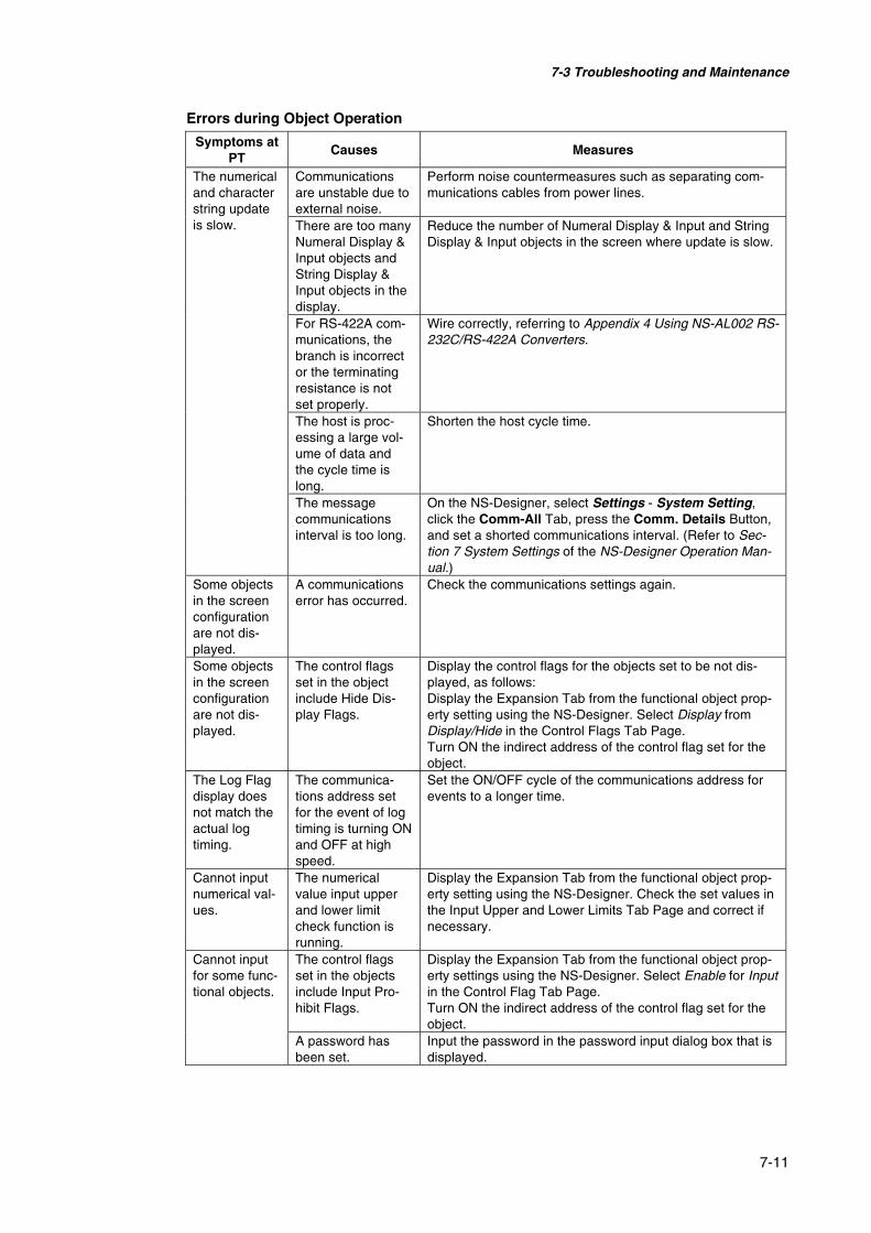
7-3 Troubleshooting and Maintenance
7-11
Errors during Object Operation
Symptoms atPT
Causes Measures
Communicationsare unstable due toexternal noise.
Perform noise countermeasures such as separating com-munications cables from power lines.
There are too manyNumeral Display &Input objects andString Display &Input objects in thedisplay.
Reduce the number of Numeral Display & Input and StringDisplay & Input objects in the screen where update is slow.
For RS-422A com-munications, thebranch is incorrector the terminatingresistance is notset properly.
Wire correctly, referring to Appendix 4 Using NS-AL002 RS-232C/RS-422A Converters.
The host is proc-essing a large vol-ume of data andthe cycle time islong.
Shorten the host cycle time.
The numericaland characterstring updateis slow.
The messagecommunicationsinterval is too long.
On the NS-Designer, select Settings - System Setting,click the Comm-All Tab, press the Comm. Details Button,and set a shorted communications interval. (Refer to Sec-tion 7 System Settings of the NS-Designer Operation Man-ual.)
Some objectsin the screenconfigurationare not dis-played.
A communicationserror has occurred.
Check the communications settings again.
Some objectsin the screenconfigurationare not dis-played.
The control flagsset in the objectinclude Hide Dis-play Flags.
Display the control flags for the objects set to be not dis-played, as follows:Display the Expansion Tab from the functional object prop-erty setting using the NS-Designer. Select Display fromDisplay/Hide in the Control Flags Tab Page.Turn ON the indirect address of the control flag set for theobject.
The Log Flagdisplay doesnot match theactual logtiming.
The communica-tions address setfor the event of logtiming is turning ONand OFF at highspeed.
Set the ON/OFF cycle of the communications address forevents to a longer time.
Cannot inputnumerical val-ues.
The numericalvalue input upperand lower limitcheck function isrunning.
Display the Expansion Tab from the functional object prop-erty setting using the NS-Designer. Check the set values inthe Input Upper and Lower Limits Tab Page and correct ifnecessary.
The control flagsset in the objectsinclude Input Pro-hibit Flags.
Display the Expansion Tab from the functional object prop-erty settings using the NS-Designer. Select Enable for Inputin the Control Flag Tab Page.Turn ON the indirect address of the control flag set for theobject.
Cannot inputfor some func-tional objects.
A password hasbeen set.
Input the password in the password input dialog box that isdisplayed.

7-3 Troubleshooting and Maintenance
7-12
Symptoms atPT
Causes Measures
The function ofthe functionalobject is notexecutedwhen pressed.
Input is disabled bythe control flag.
Input is not possible when the functional object is set to bedisabled. Correct the screen data using the NS-Designer.If the communications address set by the indirect specifica-tion is set to OFF, set the address to ON.
Cannot inputto any func-tional object.
PT is set to inputprohibit mode.
Set system memory bit $SB19 to OFF.Touch the screen and input the password to cancel dis-abling inputs.
Cannot moveto SystemMenu.
Moving to SystemMenu is prohibited.
Set system memory bit $SB3 to OFF.
There is no refer-ence file.
Use the NS-Designer to check whether the folder storingproject data contains a reference file, and resend thescreen data to the PT.
The list selec-tion andbitmap objectare blank. The number of
rows specified inthe first row of thelist selection isabove the maxi-mum.
Set the number of rows to less than the maximum.
7-4 Requesting a Replacement PT
7-13
7-4 Requesting a Replacement PT
Always observe the following precautions when faults are detected during inspection and thePT is to be replaced.
• Create a backup of the PT project data.Project data may be deleted when the PT is repaired by OMRON.
• Always turn OFF the power before replacing the PT.
• After replacing the PT, check to confirm that the new PT has no faults.
• When returning a faulty PT for repair, include a document with the Unit that provides asmany details on the fault as possible, and send to your OMRON representative.
A-1
AppendicesAppendix 1 Quick Reference..................................................................................................A-2Appendix 2 Specifications......................................................................................................A-3
A-2-1 General Specifications..............................................................................................A-3A-2-2 Characteristics ..........................................................................................................A-5A-2-3 Communications Specifications................................................................................A-6
Appendix 3 Dimensions .......................................................................................................A-10Appendix 4 Using NS-AL002 RS-232C/RS-422A Converters ............................................A-16
A-4-1 Dimensions .............................................................................................................A-16A-4-2 Mounting and Removing ........................................................................................A-17A-4-3 Specifications .........................................................................................................A-17A-4-4 DIP Switch Settings................................................................................................A-18A-4-5 Pin Arrangement.....................................................................................................A-19A-4-6 Handling the Shield on RS-422A/485 Cables.........................................................A-20A-4-7 Connection Example...............................................................................................A-22
Appendix 5 Preparing Connecting Cables............................................................................A-23A-5-1 Cable Preparation ...................................................................................................A-23A-5-2 Soldering ................................................................................................................A-24A-5-3 Hood Assembly ......................................................................................................A-24A-5-4 Preparing Connecting Cables for Host Connection ................................................A-25
Appendix 6 Preparing Cables for Computer Connection .....................................................A-27A-6-1 Connecting Cable Assembly...................................................................................A-27
Appendix 7 Preparing Connecting Cables for Bar Code Readers ........................................A-29Appendix 8 Standard Models ...............................................................................................A-31Appendix 9 List of Optional Products ..................................................................................A-43
A-9-1 Anti-reflection Sheets: NS12-KBA04, NS7-KBA04, NT30-KBA04.....................A-43A-9-2 Protective Cover: NS12-KBA05(N), NS7-KBA05(N), NT31C-KBA05(N) .........A-43A-9-3 NT30-KBA01 Chemical-resistant Cover................................................................A-44A-9-4 Replacement Battery: CJ1W-BAT01 .....................................................................A-44A-9-5 Recommended Memory Cards: ..............................................................................A-44A-9-6 Recommended Memory Card Adapter: HMC-AP001............................................A-44A-9-7 NS-CLK21 Controller Link Interface Unit .............................................................A-45A-9-8 NS-CA001/CA002 Video Input Unit .....................................................................A-45
Appendix 10 System Memory List .........................................................................................A-46Appendix 11 Differences between “–V1” Models and Other Models....................................A-49Appendix 12 NS5 System Menu ............................................................................................A-50

Appendix 1 Quick Reference
A-2
Appendix 1 Quick ReferenceThe following table provides a quick reference to NS-Designer functions and the manualsections that describe them.In the Manual section column "Programming" indicates the NS Series Programming Man-ual (V073-E1-@) and "Reference" indicates the NS Series Macro Reference provided withthe NS-Designer CD.Item Application method Manual section
Displaying straight linesor continuous straightlines
Fixed Object - Straight LineorFixed Object - Polyline
Operation: 5-2Programming:2-6
Displaying rectangles Fixed Object - Rectangle Operation: 5-2Programming:2-6
Displaying triangles,polygons, trapezoids, ordiamonds
Fixed Object - Polygon Operation: 5-2Programming:2-6
Displaying circles orovals
Fixed Object - Circle/Oval Operation: 5-2Programming:2-6
Displaying arcs Fixed Object - Arc Operation: 5-2Programming:2-6
Displaying sector Fixed Object - Sector Operation: 5-2Programming:2-6
Filling graphics Tiling Tab on the Fixed Object Property Dialog Box(Setting - Object Properties)
Programming:2-6
Displaying bitmaps Use a bitmap object (Functional Objects - Bitmap)Either BMP or JPEG files can be displayed.
Programming:2-12
Using the same graphicsin many applications
1. Select the objects to be used and register them inthe library using Tools - Register Library.
2. Display the library object using Tools - Use Li-brary.
Operation: 5-13
Displaying special sym-bols and characters
1. Create the image in a BMP or JPEG file.2. Use a bitmap object to display the image (Func-
tional Objects - Bitmap).
Programming:2-12
Displaying the samegraphics in many loca-tions or on many screens
1. Select the objects to be used and register them inthe library using Tools - Register Library.
2. Display the library object using Tools - Use Li-brary.
Operation: 5-13
1. Create a bitmap object (Functional Objects -Bitmap).
2. Use an indirect specification for the display file,enabling the displayed graphic to be changed ac-cording to changes in the PLC or PT.
Programming:2-12
Fixed ob-jects
Changing the shape of agraphic based on condi-tions
1. Create a word button object (Functional Objects -Word Button).
2. Specify Select Shape for the button shape on theGeneral Tab Page.
3. On the Color/Shape Tab Page, specify the Normalshape, Pressed, and Same as value.
Programming:2-9

Appendix 2 Specifications
A-3
Appendix 2 Specifications
A-2-1 General SpecificationsSpecifications
ItemNS12-TS0@-V1 NS10-TV0@-V1 NS8-TV@@-V1 NS5-SQ0@-V1
Rated powersupply voltage
24 VDC
Allowable voltage range 20.4 to 27.6 VDC (24 VDC ±15 %)Allowable input powerinterruption time
No restriction.
Power consumption 25 W max 15 W max.Ambient operating tem-perature
0 to 50°C(See notes 1 and 2.)
Storagetemperature
−20 to 60°C(See note 2.)
Ambient operating hu-midity]
35% to 85% (0 to 40°C) with no condensation35% to 60% (40 to 50°C) with no condensation
Operatingenvironment
No corrosive gases.
Noise immunity Conforms to IEC61000-4-4, 2 KV (power lines)Vibrationresistance(during operation)
10 to 57 Hz with 0.075 mm amplitude and 57 to 150 Hz with 9.8 m/s2 acceleration for 30min in each of X, Y, and Z directions
Shock resistance (dur-ing operation)
147 m/s2 3 times in each of X, Y, and Z directions.
Dimensions315 × 241 × 48.5 mm (W × H × D) 232 × 177 × 48.5 mm
(W × H × D)195 × 142 × 54 mm(W × H × D)
Panel cutout dimen-sions
Width 302 +10 ×
Height 228 +10 mm
Panel thickness:1.6 to 4.8 mm
Width 302 +10 ×
Height 228 +10 mm
Panel thickness:1.6 to 4.8 mm
Width 220.5 +0.50 ×
Height 165.5 +0.50 mm
Panel thickness:1.6 to 4.8 mm
Width 184 +0.50 ×
Height 131 +0.50 mm
Panel thickness:1.6 to 4.8 mm
Weight 2.5 kg max. 2.0 kg max. 1.0 kg max.Enclosure rating Front panel: Equivalent to IP65F (NEMA4) (See note 3.)
Battery life
5 years (at 25°C)The SRAM and RTC will be backed up for 5 days after the battery runs low (indicator lightsorange).The SRAM and RTC will be backed up by a super capacitor for 5 minutes after removingthe old battery (i.e., after turning ON power after 5 minutes).
Internationalstandards
UL 1604 Class 1 Division 2, EC Directives

Appendix 2 Specifications
A-4
Note 1. The operating temperature is subject to the following restrictions, depending on themounting angle and whether an Expansion Unit is installed or not.
• Without any Expansion Unit Installed- NS12-V1/NS10-V1/NS8-V1
Mounting angle of 0° to less than 30° to the horizontal:Operating temperature range of 0 to 45°C
Mounting angle of 30° to 90° or less to the horizontal:Operating temperature range of 0 to 50°C
- NS5 -V1Mounting angle of 0° to 90° or less to the horizontal:
Operating temperature range of 0 to 50°C
• With an Expansion Unit (Video Input Unit or Controller Link Unit) Installed- NS12-V1/NS10-V1
Mounting angle of 0° to less than 30° to the horizontal:Operating temperature range of 0 to 35°C
Mounting angle of 30° to 90° or less to the horizontal:Operating temperature range of 0 to 50°C
- NS8-V1Mounting angle of 0° to less than 30° to the horizontal:
Operating temperature range of 0 to 35°CMounting angle of 30° to less than 90° to the horizontal:
Operating temperature range of 0 to 45°CMounting angle of 90° to the horizontal:
Operating temperature range of 0 to 50°C
Display surface
30°
Horizontal 0°
90°
2. Operate the PT within the temperature and humidity ranges shown in the following dia-gram.
Wet-bulb temperature (°C)Storage
Temperature (°C)
Hum
idity
(R
H)
Operating
3. May not be applicable in locations with long-term exposure to oil.

Appendix 2 Specifications
A-5
A-2-2 Characteristics@ Display Specifications
SpecificationsItem
NS12-TS0@-V1 NS10-TV0@-V1 NS8-TV@@-V1 NS5-SQ0@-V1
Display device High-definition TFT color LCD STN color LCDNumber of dots 800 dot horizontal
× 600 dot vertical640 dot horizontal× 480 dot vertical
640 dot horizontal× 480 dot vertical
320 dot horizontal× 240 dot vertical
Display color 256 colors (32,000 colors for BMP/JPEG images, NS5: 4,096 colors forBMP/JPEG images)
Display area Width 246.0 mm× height 184.5mm (12.1inches)
Width 215.2 mm× height 162.4mm (10.4inches)
Width 162.2 mm× height 121.7mm (8.0 inches)
Width 117.2 mm× height 88.4mm (5.7 inches)
Displaypanel
View angle Left/right ±60°Top 45°, bottom55°
Left/right ±60°Top 35°, bottom65°
Left/right ±65°Top 55°, bottom65°
Left/right ±50°Top 30°, bottom50°
Life expectancy50,000 hours min. (See note 1.)
40,000 hours min.(See note 1.)
50,000 hours min.(See note 1.)
Brightnessadjustment
There are 3 levels of adjustment by operating the touch panel. (Seenote 2.)Backlight
(See note 4.)Backlight errordetection
Error is detected automatically,and the RUN indicator flashesgreen as notification. (See note 3.)
No detection function.
Front panelindicators
RUN Lit green: PT is operating normally.The Memory Card transfer has ended normally or a backlight error wasdetected immediately after power was turned ON. (Backlight errors arenot detected with the NS8/NS5.)Immediately after power turns ON, indicates file system check inprogress, battery low, or disconnected and operating normally.Memory Card transfer in progress.Memory Card transfer has ended abnormally.
Note 1. This is the estimated time before brightness is reduced by half at room temperature andhumidity. It is not a guaranteed value. (It is based on the middle brightness setting usingthe NS8.)The life expectancy will be drastically shortened if PT is used at low temperatures. Forexample, using the PT at temperatures of 0°C will reduce the life expectancy to approxi-mately 10,000 hours (reference value).
2. The brightness cannot be adjusted much.3. This function does not detect service life expectancy.
It detects when the backlight is not lit due to a disconnection or other errors. Backlight er-ror detection indicates that all backlights (2) are OFF.
4. Contact your nearest OMRON representative to replace the backlight.

Appendix 2 Specifications
A-6
@ Operating SpecificationsSpecifications
ItemNS12-TS0@-V1 NS10-TV0@-V1 NS8-TV@@-V1 NS5-SQ0@-V1
Method: Resistive membraneNumber of switches:1900(50 horizontal × 38vertical)16 × 16 dots foreach switch.
Number of switches:1200(40 horizontal × 30vertical)16 × 16 dots foreach switch.
Number of switches:768(32 horizontal × 24vertical)20 × 20 dots foreach switch.
Number of switches:300(20 horizontal × 15vertical)16 × 16 dots foreach switch.
Input: Pressure-sensitive
Touch panel(Matrix type)
Service life: 1,000,000 touch operations.
@ Data Capacity SpecificationsSpecifications
ItemNS12-TS0@-V1 NS10-TV0@-V1 NS8-TV@@-V1 NS5-SQ0@-V1
Standard screendata capacity
20 M NS8-TV0@-V1: 6 MNS8-TV1@-V1: 20 M
6 M
@ External Interface SpecificationsSpecifications
ItemNS12-TS0@-V1 NS10-TV0@-V1 NS8-TV@@-V1 NS5-SQ0@-V1
USB HOST 1 port (for connecting printers) NoneUSB Slave 1 port (not used)Memory cardinterface
1 ATA-Compact Flash interface slot.Used to transfer and store screen data and to store history data.
Expansion interface(See note.)
For Expansion Interface UnitsUsed to install a Controller Link Interface Unit or Video In-put Unit.
For ExpansionInterface UnitsUsed to install Ex-pansion Units spe-cially designed forthe NS5.
Note: This interface is for NS-series PTs only. Units not specified in this manual cannot be in-stalled.
@ Programming Device (Software for Creating Screen Data)Item Specifications
Name NS-DesignerModel NS-NSDC1-V@
A-2-3 Communications Specifications• Serial Communications
Item Specifications
Port A
Conforms to EIA RS-232C.D-Sub female 9-pin connector5-V output (250 mA max.) through pin 6(See note 1.)
Port B
Conforms to EIA RS-232C.D-Sub female 9-pin connector (See note 2.)5-V output (250 mA max.) through pin 6.(See note 1.)
Note 1: The 5-V output of serial ports A and B cannot be used at the same time.

Appendix 2 Specifications
A-7
Note 2: With the NS5, the Expansion Interface on the Comm Tab Page in the System Menu set-tings can be set to use a communications port in the expansion interface connector. Theexpansion interface, however, is a future expansion, which cannot yet be used. Alwaysuse the serial port B connector (D-Sub female 9-pin connector).
• 1:1 NT Link
Item SpecificationsCommunicationsstandards
Conforms to EIA RS-232C.
ConnectorsD-Sub female 9-pin connector(Serial ports A and B)
Number of Unitsconnected
1:1
Transmission distance Up to 15 m. (See note 1.)
• 1:N NT Links
Item SpecificationsCommunications stan-dards
Conforms to EIA RS-232C.
ConnectorsD-Sub female 9-pin connector(Serial ports A and B)
Number of Unitsconnected
1:1 to 8
Transmission distance Up to 15 m. (See note 2.)
Note 1. When using an NS-AL002 Adapter, the transmission distance is as follows:RS-422A cable: Up to 500 m total extended length.
2. The NS-AL002 is required when connecting two or more PTs to the host.RS-422A cable: Up to 500 m total extended length.
• Bar Code Reader
Item SpecificationsCommunicationsstandards
Conforms to EIA RS-232C.
Communicationssettings
Start-stop synchronizationBaud rate: 4,800, 9,600, or 19,200 bpsData length: 7 or 8 bitsStop bits: 1 or 2 bitsParity: None, odd, or evenFlow control: RS/CS control
Ports that can beconnected
Either port A or port B only.
Number of Unitsconnected
1:1
Using PT serial port and D-Sub 6-pin Using external power supplyTransmission dis-tance 2 m 15 mCommunicationsprotocol
No protocol mode
Data format [STX] Data (0 to 40 bytes) [ETX]
Using PT serial port and D-Sub 6-pin Using external power supplyPower supply
5 V ±5% 250 mA max.Depends on Bar Code Readerspecifications.

Appendix 2 Specifications
A-8
@ Ethernet Specifications (NS12-TS01(B)-V1, NS10-TV01(B)-V1, NS8-TV@1(B)-V1, NS5-SQ01(B)-V1)
Item SpecificationsConformance standards Conforms to IEEE 802.3 / Ethernet (10/100Base-T).Transmission medium 2 pair Cat 3 UTP 22 to 26AWG, Cat 5, Cat 5e, Cat 6Transmission distance 100 m (node-to-hub and hub-to-hub)Connector 8-pin modular connector
• Ethernet
Item SpecificationsNetwork address 1 to 127Node address 1 to 254UDP port number 1024 to 65535 (See note 1.)IP address 0.0.0.0 to 255.255.255.255 (See note 2.)Subnet mask 0.0.0.0 to 255.255.255.255Default gateway 0.0.0.0 to 255.255.255.255IP proxy address “”(blank), 0.0.0.0 to 255.255.255.255
Conversion tableNode address: 1 to 253IP address: 0.0.0.0 to 255.255.255.255
Note 1. The default UDP port number is 9600.2. Do not set the following values for the IP address.
• Host ID with all bits set to 0 or 1. (Example: 192.168.21.0)• Net ID with all bits set to 0 or 1. (Example: 255.255.21.16)• Subnet ID with all bits set to 1. (Example: 192.168.255.16)• IP addresses that begin with 127. (Example: 127.35.21.16)
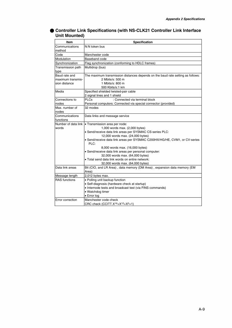
Appendix 2 Specifications
A-9
@ Controller Link Specifications (with NS-CLK21 Controller Link InterfaceUnit Mounted)
Item SpecificationCommunicationsmethod
N:N token bus
Code Manchester codeModulation Baseband codeSynchronization Flag synchronization (conforming to HDLC frames)Transmission pathtype
Multidrop (bus)
Baud rate andmaximum transmis-sion distance
The maximum transmission distances depends on the baud rate setting as follows:2 Mbits/s: 500 m1 Mbits/s: 800 m500 Kbits/s:1 km
Media Specified shielded twisted-pair cable2 signal lines and 1 shield
Connections tonodes
PLCs : Connected via terminal blockPersonal computers: Connected via special connector (provided)
Max. number ofnodes
32 modes
Communicationsfunctions
Data links and message service
Number of data linkwords
• Transmission area per node:1,000 words max. (2,000 bytes)
• Send/receive data link areas per SYSMAC CS-series PLC:12,000 words max. (24,000 bytes)
• Send/receive data link areas per SYSMAC C200HX/HG/HE, CVM1, or CV-seriesPLC:
8,000 words max. (16,000 bytes)• Send/receive data link areas per personal computer:
32,000 words max. (64,000 bytes)• Total send data link words on entire network:
32,000 words max. (64,000 bytes)Data link areas Bit (CIO, and LR Area) , data memory (DM Area) , expansion data memory (EM
Area)Message length 2,012 bytes max.RAS functions • Polling unit backup function
• Self-diagnosis (hardware check at startup)• Internode tests and broadcast test (via FINS commands)• Watchdog timer• Error log
Error correction Manchester code checkCRC check (CCITT.X16+X12+X5+1)
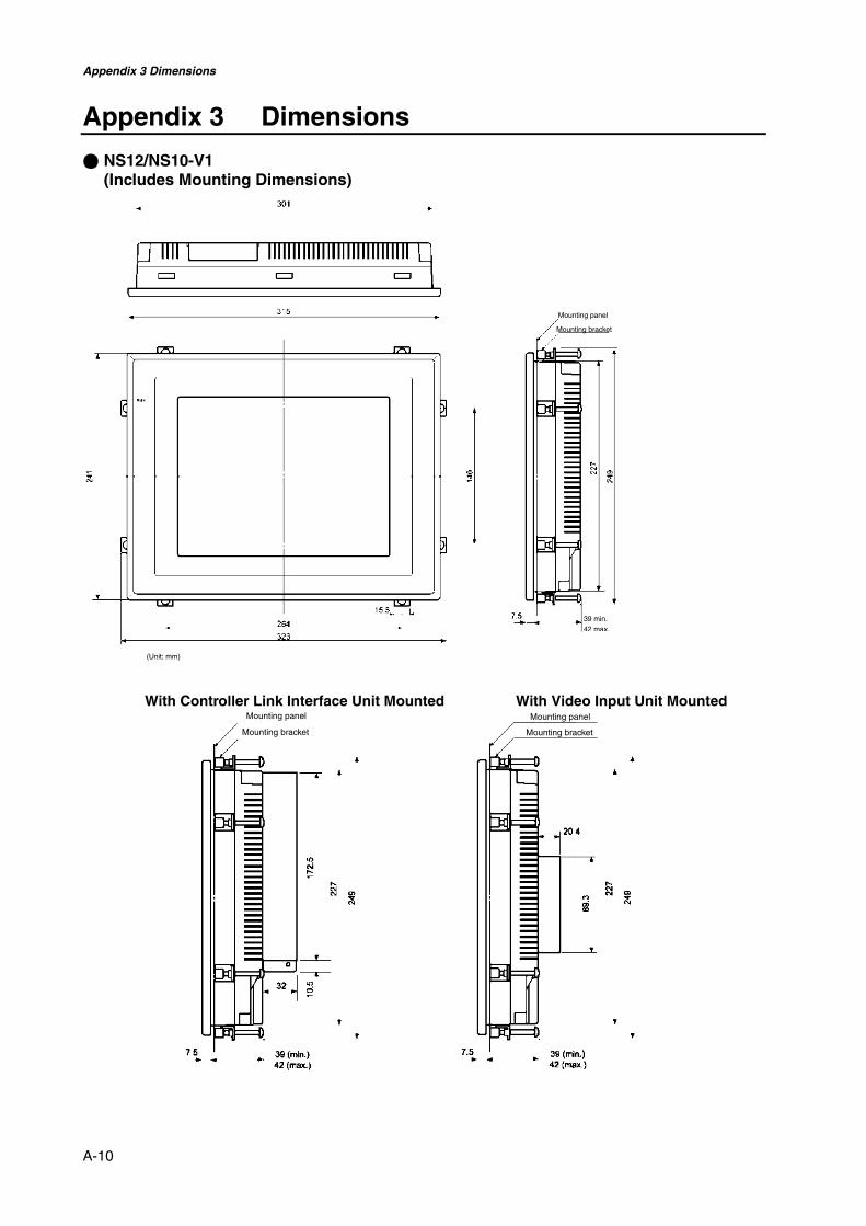
Appendix 3 Dimensions
A-10
39 min.42 max.
(Unit: mm)
Appendix 3 Dimensions
@ NS12/NS10-V1(Includes Mounting Dimensions)
With Controller Link Interface Unit Mounted With Video Input Unit Mounted
Mounting panel
Mounting bracket
Mounting panel
Mounting bracket
Mounting panel
Mounting bracket

Appendix 3 Dimensions
A-11
@ NS12/NS10-V1 Cable Connection Dimensions72
.8
78.0
5
4.3
SW
50.7
24VDC
HOST SLAVEETHERNET
PORTB PORTA
RESET
83.5
30.7
8
90.4
49.9
13.73.8
23.1
28.6
329
.99
31.1
@ NS12/NS10 (without “V1”) Cable Connection Dimensions
90.2
ETHERNET PORT A PORT B
69.5
59.4 4.
3
31.5
30.8
10360
20

Appendix 3 Dimensions
A-12
@ NS8-V1 Cable Connection Dimensions
39 min.
42 max.
(Unit: mm)
Mounting panelMounting bracket
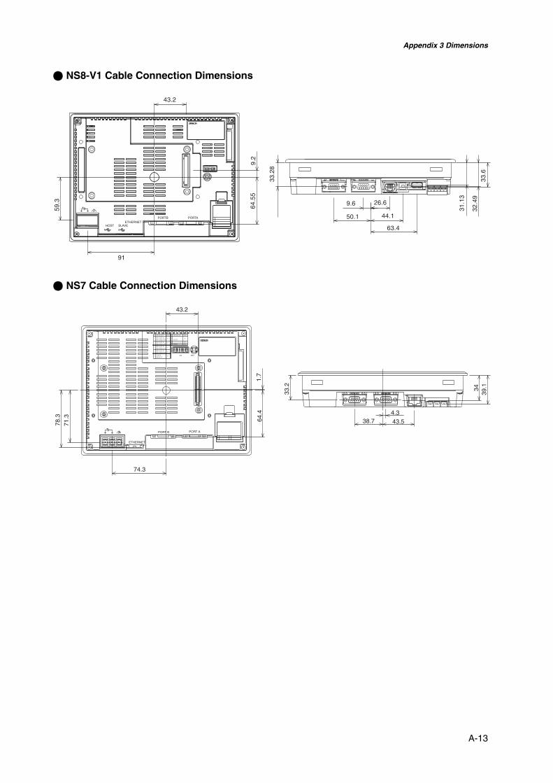
Appendix 3 Dimensions
A-13
@ NS8-V1 Cable Connection Dimensions
91
59.3
43.2
9.2
64.5
5
HOST SLAVEETHERNET
PORTAPORTB
9.6 26.6
50.1 44.1
63.4
31.1
3
32.4
933
.6
33.2
8
@ NS7 Cable Connection Dimensions
78.3
71.3
74.3
43.2
1.7
64.4
ETHERNET
PORT B PORT A
33.2
38.74.3
43.5
3439
.1

Appendix 3 Dimensions
A-14
@ NS5-V1 Dimensions
Mounting panelMounting bracket

Appendix 3 Dimensions
A-15
@ NS5-V1 Cable Connection Dimensions

Appendix 4 Using NS-AL002 RS-232C/RS-422A Converters
A-16
Appendix 4 Using NS-AL002 RS-232C/RS-422AConverters
The NS-AL002 RS-232C/RS-422A Converter is connected directly to RS-232C port A or Bof the PT, and converts RS-232C communications to RS-422A/RS-485. Any of the Con-verters listed in Appendix 8 Standard Models can be used. A summary of the NS-AL002external dimensions, mounting and removal methods, and specifications are providedhere. Refer to this information when designing the control panel. Refer to the InstructionSheet included with the NS-AL002 for details.
A-4-1 Dimensions
Mounting screws (2)
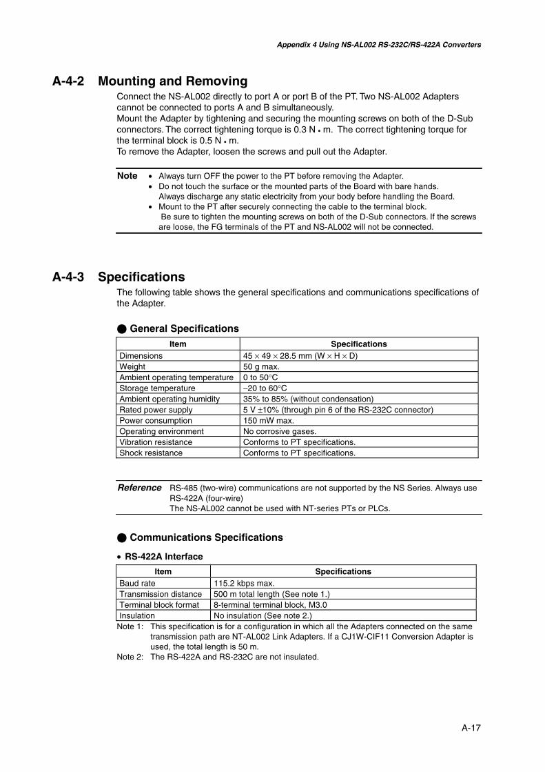
Appendix 4 Using NS-AL002 RS-232C/RS-422A Converters
A-17
A-4-2 Mounting and RemovingConnect the NS-AL002 directly to port A or port B of the PT. Two NS-AL002 Adapterscannot be connected to ports A and B simultaneously.Mount the Adapter by tightening and securing the mounting screws on both of the D-Subconnectors. The correct tightening torque is 0.3 N • m. The correct tightening torque forthe terminal block is 0.5 N • m.To remove the Adapter, loosen the screws and pull out the Adapter.
Note • Always turn OFF the power to the PT before removing the Adapter.• Do not touch the surface or the mounted parts of the Board with bare hands.
Always discharge any static electricity from your body before handling the Board.• Mount to the PT after securely connecting the cable to the terminal block.
Be sure to tighten the mounting screws on both of the D-Sub connectors. If the screwsare loose, the FG terminals of the PT and NS-AL002 will not be connected.
A-4-3 SpecificationsThe following table shows the general specifications and communications specifications ofthe Adapter.
@ General SpecificationsItem Specifications
Dimensions 45 × 49 × 28.5 mm (W × H × D)Weight 50 g max.Ambient operating temperature 0 to 50°CStorage temperature −20 to 60°CAmbient operating humidity 35% to 85% (without condensation)Rated power supply 5 V ±10% (through pin 6 of the RS-232C connector)Power consumption 150 mW max.Operating environment No corrosive gases.Vibration resistance Conforms to PT specifications.Shock resistance Conforms to PT specifications.
Reference RS-485 (two-wire) communications are not supported by the NS Series. Always useRS-422A (four-wire)The NS-AL002 cannot be used with NT-series PTs or PLCs.
@ Communications Specifications
• RS-422A Interface
Item SpecificationsBaud rate 115.2 kbps max.Transmission distance 500 m total length (See note 1.)Terminal block format 8-terminal terminal block, M3.0Insulation No insulation (See note 2.)
Note 1: This specification is for a configuration in which all the Adapters connected on the sametransmission path are NT-AL002 Link Adapters. If a CJ1W-CIF11 Conversion Adapter isused, the total length is 50 m.
Note 2: The RS-422A and RS-232C are not insulated.

Appendix 4 Using NS-AL002 RS-232C/RS-422A Converters
A-18
A-4-4 DIP Switch SettingsThe Adapter has four DIP switch pins for setting the RS-422A communications conditions.Set the DIP switch pins before connecting the cables to the Adapter.
ON OFFDIP switch
The factory setting for the DIP switch is all pins set to OFF.Pin Function ON OFF
Pin 1 Transmission mode RS/CS control Normal transmission Pins 2 and 3 Two-wire/four-wire method selection Two-wire method Four-wire method Pin 4 Terminating resistance Yes None
For 1:1 NT Link, set the RS-422A transmission mode to normal transmission (pin 1 OFF).For 1:N NT Links (normal, high speed), set the RS-422A transmission mode to RS/CScontrol (pin 1 ON).
Note • DIP Switch Settings When Using a CJ1W-CIF11 Conversion Adapter
Pin Function Setting
Pin 1 Terminating resistance selectionON: Terminating resistance enabledOFF: Terminating resistance disabled
Pin 2 Two-wire/four-wire method selection OFF Pin 3 Two-wire/four-wire method selection OFF Pin 4 Not used. --- Pin 5 Selection of RS control for RD OFF Pin 6 Selection of RS control for SD ON
• When a CJ1W-CIF11 Conversion Adapter is used, the total transmission length is 50 m.• If NT-001/NT-002 Link Adapters are used together with CJ1W-CIF11 Conversion Adapt-
ers on the same transmission path, the total transmission length is also 50 m.• For details, refer to the Appendix G in the SYSMAC CJ Series Operation Manual
(W393).• Make sure that both of the mounting screws on the D-Sub connector are tightened to a
torque of 0.3 N⋅m

Appendix 4 Using NS-AL002 RS-232C/RS-422A Converters
A-19
A-4-5 Pin ArrangementThe Adapter has a connector for RS-232C interface connection and a terminal block forRS-422A/485 interface connection.The pin arrangements for the RS-232C connector and RS-422A/485 terminal block are asfollows:
@ RS-232C Connector
Terminal blockpin number
Signal nameSignal direction
Adapter ⇔ PT
1 NC 2 RD ← 3 SD → 4 CS ← (RS signal short-circuited internally) 5 RS →
6 5 V (30 mA max.)
←
7 or 8 NC (Pins 7 and 8 are short-circuited.) 9 SG −
Connector hood FG Connects to functional ground terminal ofPT.
@ RS-422A Terminal Block
Terminal blockpin number
Signal nameSignal directionAdapter ⇔ Host
1 FG Connects to functional ground terminal of PT. 2 RDB (+) ← 3 SDB (+) → 4 RSB (+) → 5 NC --- 6 RDA (−) ← 7 SDA (−) → 8 RSA (−) →
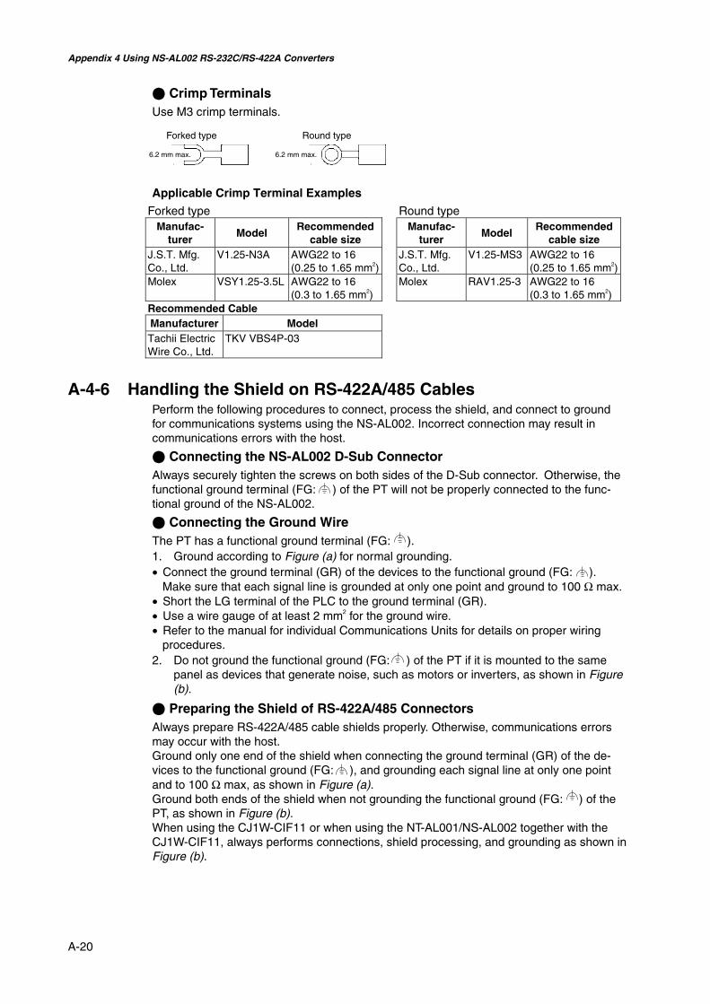
Appendix 4 Using NS-AL002 RS-232C/RS-422A Converters
A-20
@ Crimp TerminalsUse M3 crimp terminals.
Applicable Crimp Terminal Examples
Forked type Round typeManufac-
turerModel
Recommendedcable size
Manufac-turer
ModelRecommended
cable sizeJ.S.T. Mfg.Co., Ltd.
V1.25-N3A AWG22 to 16(0.25 to 1.65 mm2)
J.S.T. Mfg.Co., Ltd.
V1.25-MS3 AWG22 to 16(0.25 to 1.65 mm2)
Molex VSY1.25-3.5L AWG22 to 16(0.3 to 1.65 mm2)
Molex RAV1.25-3 AWG22 to 16(0.3 to 1.65 mm2)
Recommended CableManufacturer ModelTachii ElectricWire Co., Ltd.
TKV VBS4P-03
A-4-6 Handling the Shield on RS-422A/485 CablesPerform the following procedures to connect, process the shield, and connect to groundfor communications systems using the NS-AL002. Incorrect connection may result incommunications errors with the host.
@ Connecting the NS-AL002 D-Sub ConnectorAlways securely tighten the screws on both sides of the D-Sub connector. Otherwise, thefunctional ground terminal (FG: ) of the PT will not be properly connected to the func-tional ground of the NS-AL002.
@ Connecting the Ground WireThe PT has a functional ground terminal (FG: ).1. Ground according to Figure (a) for normal grounding.• Connect the ground terminal (GR) of the devices to the functional ground (FG: ).
Make sure that each signal line is grounded at only one point and ground to 100 Ω max.• Short the LG terminal of the PLC to the ground terminal (GR).• Use a wire gauge of at least 2 mm2 for the ground wire.• Refer to the manual for individual Communications Units for details on proper wiring
procedures.2. Do not ground the functional ground (FG: ) of the PT if it is mounted to the same
panel as devices that generate noise, such as motors or inverters, as shown in Figure(b).
@ Preparing the Shield of RS-422A/485 ConnectorsAlways prepare RS-422A/485 cable shields properly. Otherwise, communications errorsmay occur with the host.Ground only one end of the shield when connecting the ground terminal (GR) of the de-vices to the functional ground (FG: ), and grounding each signal line at only one pointand to 100 Ω max, as shown in Figure (a).Ground both ends of the shield when not grounding the functional ground (FG: ) of thePT, as shown in Figure (b).When using the CJ1W-CIF11 or when using the NT-AL001/NS-AL002 together with theCJ1W-CIF11, always performs connections, shield processing, and grounding as shown inFigure (b).
Forked type Round type
6.2 mm max. 6.2 mm max.

Appendix 4 Using NS-AL002 RS-232C/RS-422A Converters
A-21
CPU Rack
FGRS-422A/485
Signal line
NS-AL002
PT
NS-AL002
PT
NS-AL002
PT
LG GR
FG
FG
@ Example of Recommended Wiring
Figure (a) Figure (b)
CPU Unit orCommuni-cations Unit
PowersupplyUnit
FG
NS-AL002
PT
NS-AL002
PT
NS-AL002
PT
LG GR
FG
FG
CPU Rack
CPU Unit orCommuni-cations Unit
PowersupplyUnit
RS-422A/485
Signal line

Appendix 4 Using NS-AL002 RS-232C/RS-422A Converters
A-22
A-4-7 Connection Example
An example of connecting a PLC and a PT using an RS-232C/RS-422A Converter isshown below. Use the wiring example as reference for correct wiring.
@ Wiring Example
Note: Refer to A-4-6 Handling the Shield on RS-422A/485 Cables for information on processingthe shield wire on the RS-442A/485 cable.
CPU Rack PT (unit No. 0) PT (unit No. 1)
RS-422A Converter (CJ1W-CIF11)
RS-422A Converter (NS-AL002)
RS-422A Converter (NS-AL002)
1:N NT Link
Built-in RS-232C port on PCU unit
NS-AL002DIP switch settings
SW1SW2SW3SW4SW5SW6
2/4-wire2/4-wireNot used.RD controlSD control
CPU Rack
ON (Yes)OFF (4-wire)OFF (4-wire)OFFOFFON
RD
A-
RD
B+
SD
A-
SD
B+
FG
ON (RS/CS control) OFF (4-wire)OFF (4-wire)OFF (None)
RD
A-
RD
B+
SD
A-
SD
B+
FG
RD
A-
RD
B+
SD
A-
SD
B+
FG
CJ1W-CIF11DIP switch settings
SW1SW2SW3SW4
2/4-wire2/4-wire
PT (unit No. 0)
PT (unit No. 1)
ON (RS/CS control) OFF (4-wire)OFF (4-wire)ON (Yes) Terminating resistance
RS/CS control/Always sendTerminating resistance
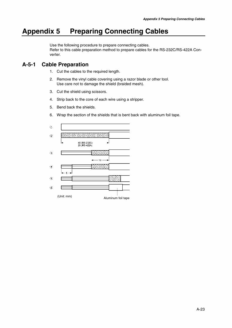
Appendix 5 Preparing Connecting Cables
A-23
Appendix 5 Preparing Connecting Cables
Use the following procedure to prepare connecting cables.Refer to this cable preparation method to prepare cables for the RS-232C/RS-422A Con-verter.
A-5-1 Cable Preparation1. Cut the cables to the required length.
2. Remove the vinyl cable covering using a razor blade or other tool.Use care not to damage the shield (braided mesh).
3. Cut the shield using scissors.
4. Strip back to the core of each wire using a stripper.
5. Bend back the shields.
6. Wrap the section of the shields that is bent back with aluminum foil tape.
(Unit: mm) Aluminum foil tape

Appendix 5 Preparing Connecting Cables
A-24
A-5-2 Soldering1. Pass a heat-shrinking tube over each wire.
2. Pre-solder each wire and connector terminal.
3. Solder each of the wires to the connector terminals.
4. Replace the heat-shrinking tube up to the soldered section, and shrink the tube ontothe wire by applying heat using a soldering gun.
A-5-3 Hood AssemblyAssemble the hood as shown in the following diagram.
Heat-shrinking tubeInternal diameter: 1.5Length = 10
Soldering iron
Heat-shrinking tube
Aluminum foil tapeEnd with Connector End without Connector
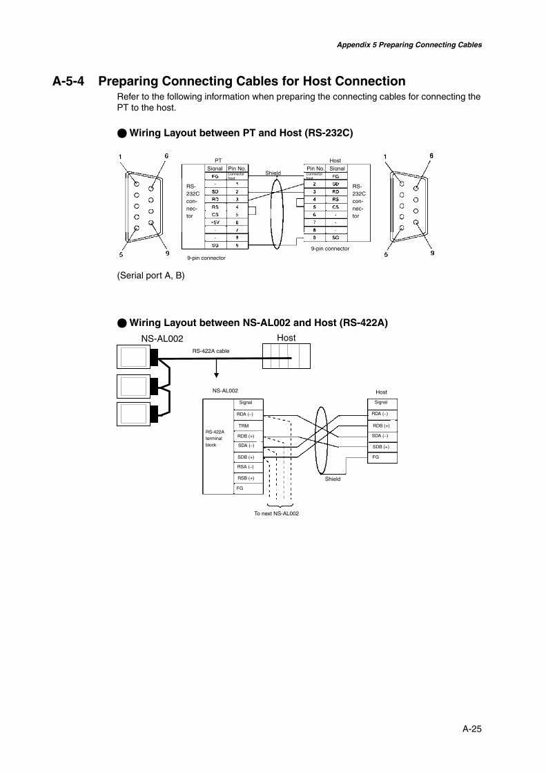
Appendix 5 Preparing Connecting Cables
A-25
A-5-4 Preparing Connecting Cables for Host ConnectionRefer to the following information when preparing the connecting cables for connecting thePT to the host.
@ Wiring Layout between PT and Host (RS-232C)
(Serial port A, B)
@ Wiring Layout between NS-AL002 and Host (RS-422A)HostNS-AL002
RS-422A cable
NS-AL002 Host
Signal
RS-422Aterminalblock
RDA (−)
TRM
RDB (+)
SDA (−)
SDB (+)
RSA (−)
RSB (+)
FG
FG
RDA (−)
RDB (+)
SDA (−)
SDB (+)
Shield
To next NS-AL002
Signal
Connectorfood
SignalPT Host
ShieldSignal Pin No.
Connectorfood
Pin No.
RS-232Ccon-nec-tor
9-pin connector
RS-232Ccon-nec-tor
9-pin connector
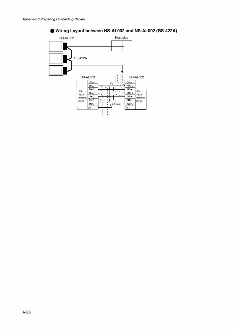
Appendix 5 Preparing Connecting Cables
A-26
@ Wiring Layout between NS-AL002 and NS-AL002 (RS-422A)
Host sideNS-AL002
RS-422A
NS-AL002 NS-AL002
Shield
RS-422Aterminalblock
RS-422Aterminalblock
Signal Signal
FG FG

Appendix 6 Preparing Cables for Computer Connection
A-27
Appendix 6 Preparing Cables for Computer Connec-tion
Refer to the following information when preparing the NS-Designer connecting cables.
A-6-1 Connecting Cable AssemblyWire the RS-232C connector to the DOS or 98-NX computer according to the type, asfollows:
• 25-pin Connector
Use the following products to assemble the connecting cable.
Name Model DetailsXM2D-2501 25-pin type
Manufactured by OMRON (computer side)Connector
XM2A-0901 9-pin typeManufactured by OMRON (PT side)
XM2S-2511 25-pin typeManufactured by OMRON (computer side)
Connectorhood
XM2S-0911 9-pin type, mm screwsManufactured by OMRON (PT side)
AWG28 × 5P IFVV-SB Multiconductor shielded cableManufactured by Fujikura Densen.
Cable
CO-MA-VV-SB 5P × 28AWG Multiconductor shielded cableManufactured by Hitachi Densen.
Computer
Connector hood
Shield
PT serial port
Connector hood

Appendix 6 Preparing Cables for Computer Connection
A-28
• 9-pin Connector
Use the following products to assemble the connecting cable.
Name Model DetailsXM2D-0901 9-pin type
Manufactured by OMRON (computer side)Connector
XM2A-0901 9-pin typeManufactured by OMRON (PT side)
XM2S-0911 9-pin type, mm screwsManufactured by OMRON.
Connectorhood(See note.) XM2S-0913 9-pin type, inch screws
Manufactured by OMRON.AWG28 × 5P IFVV-SB Multiconductor shielded cable
Manufactured by Fujikura Densen.Cable
CO-MA-VV-SB 5P × 28AWG Multiconductor shielded cableManufactured by Hitachi Densen.
Note: Use a connector hood for the computer that conforms to the standards for the screws of thecomputer connector.
Computer
Connector hood
Shield
PT serial port
Connector hood

Appendix 7 Preparing Connecting Cables for Bar Code Readers
A-29
Appendix 7 Preparing Connecting Cables for BarCode Readers
Refer to the following information when preparing the connecting cables for connecting theV520-RH21-6 Bar Code Reader.
• Connector Pin Arrangement
Pinnumber
Signal name Abbreviation Signal directionV520-RH21-6 PT
1 Send data SD (TXD)2 Receive data RD (RXD)3 Request to send RS (RTS)4 Clear to send CS (CTS)5 Not connected.6 Data terminal ready ER (DTR)7 0 V SG8 Power supply (Vcc) +5 V
• Wiring Method
When connecting to the 5-V output of the PT’s serial port, use a cable length of less than2 m. If the cable is 2 m or longer, connect pins 7 and 8 of the Bar Code Reader to an ex-ternal power supply.
1
2
3
45
7
8
Connector pinarrangement atcomputer
PT V520-RH21-6
RS-232Cinterface
Signal Pin No. Signal Pin No.
6

Appendix 7 Preparing Connecting Cables for Bar Code Readers
A-30
• Connector Types
Use the following products to assemble the connecting cable.
Name Model DetailsXM2A-0901 9-pin type
Manufactured by OMRON (PT side)Connector
TCS2280-01-2011 8-pin DIN type Hoshiden, Co., Ltd.Panel-mounting type
Connector hood XM2S-0911 9-pin typeManufactured by OMRON.
AWG28 × 5P IFVV-SB Multiconductor shielded cableManufactured by Fujikura Densen.
Cable
CO-MA-VV-SB 5P × 28AWG Multiconductor shielded cableManufactured by Hitachi Densen.

Appendix 8 Standard Models
A-31
Appendix 8 Standard Models
Programmable Terminals (PTs)
LCD Pre-install system CaseModel
Type Size ColorNumberof dots
EthernetLanguage
ApplicablePLC
Color
NS12-TS01-V1
TFT 12.1 inch Color 800 × 600 10/100Base-T English/Japanese
OMRON Ivory
NS12-TS01B-V1
TFT 12.1 inch Color 800 × 600 10/100Base-T English/Japanese
OMRON Black
NS12-TS00-V1
TFT 12.1 inch Color 800 × 600 Not supported. English/Japanese
OMRON Ivory
NS12-TS00B-V1
TFT 12.1 inch Color 800 × 600 Not supported. English/Japanese
OMRON Black
NS10-TV01-V1
TFT 10.4 inch Color 640 × 480 10/100Base-T English/Japanese
OMRON Ivory
NS10-TV01B-V1
TFT 10.4 inch Color 640 × 480 10/100Base-T English/Japanese
OMRON Black
NS10-TV00 -V1
TFT 10.4 inch Color 640 × 480 Not supported. English/Japanese
OMRON Ivory
NS10-TV00B-V1
TFT 10.4 inch Color 640 × 480 Not supported. English/Japanese
OMRON Black
NS8-TV01-V1(See note.)
TFT 8.0 inch Color 640 × 480 10/100Base-T English/Japanese
OMRON Ivory
NS8-TV01B-V1 (Seenote.)
TFT 8.0 inch Color 640 × 480 10/100Base-T English/Japanese
OMRON Black
NS8-TV11-V1(See note.)
TFT 8.0 inch Color 640 × 480 10/100Base-T English/Japanese
OMRON Ivory
NS8-TV11B-V1 (Seenote.)
TFT 8.0 inch Color 640 × 480 10/100Base-T English/Japanese
OMRON Black
NS8-TV00 -V1 (Seenote.)
TFT 8.0 inch Color 640 × 480 Not supported. English/Japanese
OMRON Ivory
NS8-TV00B-V1 (Seenote.)
TFT 8.0 inch Color 640 × 480 Not supported. English/Japanese
OMRON Black
NS8-TV10 -V1 (Seenote.)
TFT 8.0 inch Color 640 × 480 Not supported. English/Japanese
OMRON Ivory
NS8-TV10B-V1 (Seenote.)
TFT 8.0 inch Color 640 × 480 Not supported. English/Japanese
OMRON Black
NS5-SQ01-V1
STN 5.7 inch Color 320 × 240 10/100Base-T English/Japanese
OMRON Ivory
NS5-SQ01B-V1
STN 5.7 inch Color 320 × 240 10/100Base-T English/Japanese
OMRON Black
NS5-SQ00-V1
STN 5.7 inch Color 320 × 240 Not supported. English/Japanese
OMRON Ivory
NS5-SQ00B-V1
STN 5.7 inch Color 320 × 240 Not supported. English/Japanese
OMRON Black
Note: The capacity of the NS8-TV00/TV01(B)-V1 is 6 Mbytes and the capacity of the NS8-TV10/TV11(B)-V1 is 20 Mbytes.
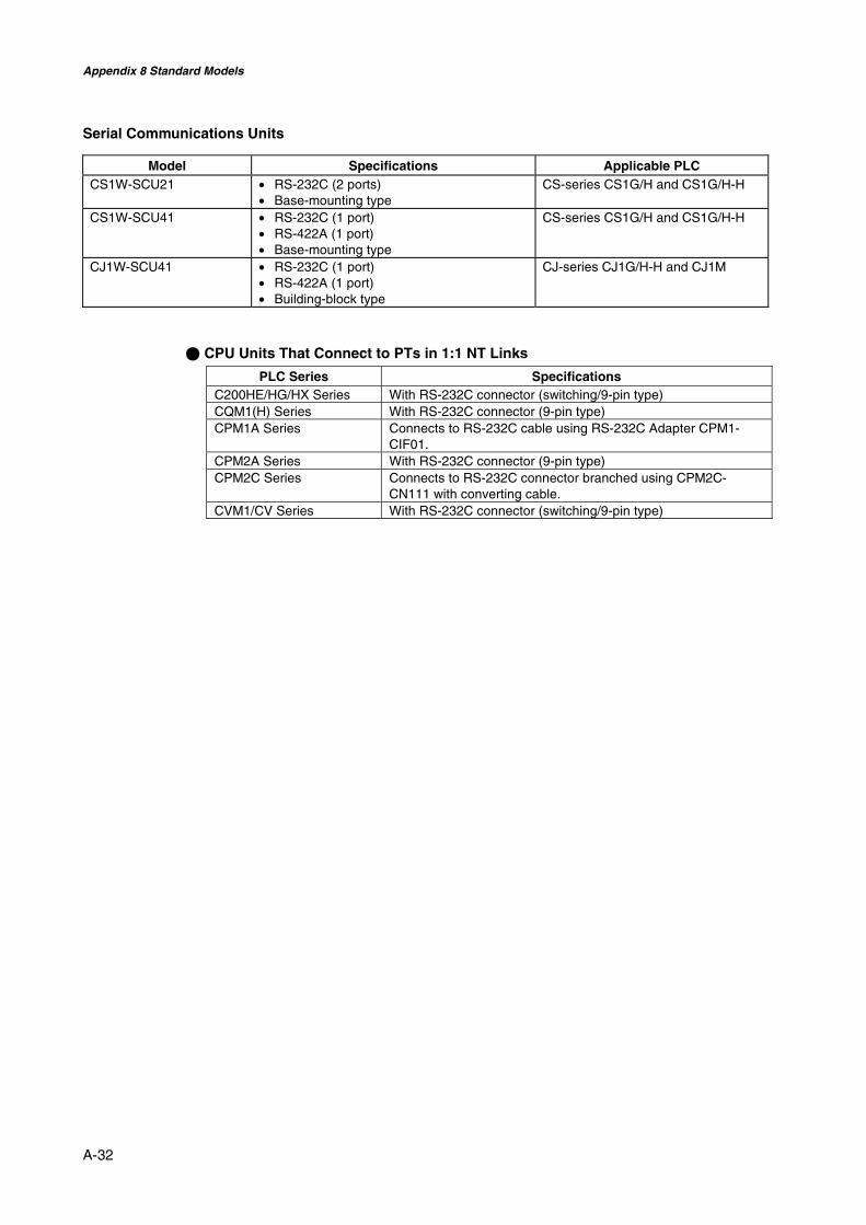
Appendix 8 Standard Models
A-32
Serial Communications Units
Model Specifications Applicable PLCCS1W-SCU21 • RS-232C (2 ports)
• Base-mounting typeCS-series CS1G/H and CS1G/H-H
CS1W-SCU41 • RS-232C (1 port)• RS-422A (1 port)• Base-mounting type
CS-series CS1G/H and CS1G/H-H
CJ1W-SCU41 • RS-232C (1 port)• RS-422A (1 port)• Building-block type
CJ-series CJ1G/H-H and CJ1M
@ CPU Units That Connect to PTs in 1:1 NT Links
PLC Series SpecificationsC200HE/HG/HX Series With RS-232C connector (switching/9-pin type)CQM1(H) Series With RS-232C connector (9-pin type)CPM1A Series Connects to RS-232C cable using RS-232C Adapter CPM1-
CIF01.CPM2A Series With RS-232C connector (9-pin type)CPM2C Series Connects to RS-232C connector branched using CPM2C-
CN111 with converting cable.CVM1/CV Series With RS-232C connector (switching/9-pin type)

Appendix 8 Standard Models
A-33
CPU Units That Connect in 1:1 NT Links via RS-232C to PT Serial Ports
PLC Series CPU Units with built-in 1:1 NT Linkfunctionality
CPU Units that connect via op-tional Communications Boards
C200HS-CPU21C200HS-CPU23C200HS-CPU31C200HS-CPU33
---
C200HE-CPU32 (-Z) (See note 1.)C200HE-CPU42 (-Z) (See note 1.)
C200HE-CPU32 (-Z) (See note 1.)C200HE-CPU42 (-Z) (See note 1.)
C200HG-CPU33(-Z)C200HG-CPU43(-Z)C200HG-CPU53(-Z)C200HG-CPU63(-Z)
C200HG-CPU33(-Z) (See note 1.)C200HG-CPU43(-Z) (See note 1.)C200HG-CPU53(-Z) (See note 1.)C200HG-CPU63(-Z) (See note 1.)
C200HX-CPU34(-Z)C200HX-CPU44(-Z)C200HX-CPU54(-Z)C200HX-CPU64(-Z)C200HX-CPU65-ZC200HX-CPU85-Z
C200HX-CPU34(-Z) (See note 1.)C200HX-CPU44(-Z) (See note 1.)C200HX-CPU54(-Z) (See note 1.)C200HX-CPU64(-Z) (See note 1.)
CQM1-CPU41-V1CQM1-CPU42-V1CQM1-CPU43-V1CQM1-CPU44-V1CQM1-CPU45-EV1
---
CPM1A-10CD@-@ (-V1)CPM1A-20CD@-@ (-V1)CPM1A-30CD@-@ (-V1)CPM1A-40CD@-@ (-V1)
---
CPM2A-30CD@@-@CPM2A-40CD@@-@CPM2A-60CD@@-@
---
CPM2C-10@@@@@@-@ (See note 4.)CPM2C-20@@@@@@-@ (See note 4.)
---
C Series
CQM1H-CPU21 (See note 2.)CQM1H-CPU51 (See note 2.)CQM1H-CPU61 (See note 2.)
---
CV Series(See note 3.)
CV500-CPU01-V1CV1000-CPU01-V1CV2000-CPU01-V1
---
CVM1 Series(See note 3.)
CVM1-CPU01-V2CVM1-CPU11-V2CVM1-CPU21-V2
---
Note 1. A C200HW-COM02/COM04/COM05/COM06-V1 Communications Board is required.2. A CQM1H-SCB41 Serial Communications Board is required.3. Connection is not possible to CVM1/CV-series PLC CPU Units without “-V1” in the
model number.4. A CS1W-CN118 Conversion Cable or XW2Z-200T-2 Cable with connector must be used
for the connection.
Reference • CS-series CPU Units cannot connect to 1:1 NT Links, but a 1:1 connection can bemade using 1:N NT Links (normal or high-speed). Refer to 4-2 1:N Host Connec-tion and 4-3 High-speed 1:N NT Links for details.
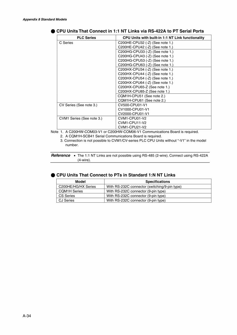
Appendix 8 Standard Models
A-34
@ CPU Units That Connect in 1:1 NT Links via RS-422A to PT Serial PortsPLC Series CPU Units with built-in 1:1 NT Link functionality
C200HE-CPU32 (-Z) (See note 1.)C200HE-CPU42 (-Z) (See note 1.)C200HG-CPU33 (-Z) (See note 1.)C200HG-CPU43 (-Z) (See note 1.)C200HG-CPU53 (-Z) (See note 1.)C200HG-CPU63 (-Z) (See note 1.)C200HX-CPU34 (-Z) (See note 1.)C200HX-CPU44 (-Z) (See note 1.)C200HX-CPU54 (-Z) (See note 1.)C200HX-CPU64 (-Z) (See note 1.)C200HX-CPU65-Z (See note 1.)C200HX-CPU85-Z (See note 1.)
C Series
CQM1H-CPU51 (See note 2.)CQM1H-CPU61 (See note 2.)
CV Series (See note 3.) CV500-CPU01-V1CV1000-CPU01-V1CV2000-CPU01-V1
CVM1 Series (See note 3.) CVM1-CPU01-V2CVM1-CPU11-V2CVM1-CPU21-V2
Note 1. A C200HW-COM03-V1 or C200HW-COM06-V1 Communications Board is required.2. A CQM1H-SCB41 Serial Communications Board is required.3. Connection is not possible to CVM1/CV-series PLC CPU Units without “-V1” in the model
number.
Reference • The 1:1 NT Links are not possible using RS-485 (2-wire). Connect using RS-422A(4-wire).
@ CPU Units That Connect to PTs in Standard 1:N NT LinksModel Specifications
C200HE/HG/HX Series With RS-232C connector (switching/9-pin type)CQM1H Series With RS-232C connector (9-pin type)CS Series With RS-232C connector (9-pin type)CJ Series With RS-232C connector (9-pin type)

Appendix 8 Standard Models
A-35
CPU Units That Connect in 1:N NT Links via RS-232C to PT Serial Ports
PLC Series Connecting with built-in ports Connecting via optional Commu-nications Boards
CS Series CS1G-CPU42(-V1)CS1G-CPU43(-V1)CS1G-CPU44(-V1)CS1G-CPU45(-V1)CS1H-CPU63(-V1)CS1H-CPU64(-V1)CS1H-CPU65(-V1)CS1H-CPU66(-V1)CS1H-CPU67(-V1)CS1G-CPU42HCS1G-CPU43HCS1G-CPU44HCS1G-CPU45HCS1H-CPU63HCS1H-CPU64HCS1H-CPU65HCS1H-CPU66HCS1H-CPU67HCS1D-CPU65HCS1D-CPU67H
Same as at left (see note 1).
CJ Series CJ1G-CPU42H (See note 2.)CJ1G-CPU43H (See note 2.)CJ1G-CPU44H (See note 2.)CJ1G-CPU45H (See note 2.)CJ1M-CPU12CJ1M-CPU13CJ1M-CPU22CJ1M-CPU23CJ1H-CPU65H (See note 2.)CJ1H-CPU66H (See note 2.)
Same as at left (see note 2).
C200HE-CPU42(-Z) C200HE-CPU32(-Z) (See note 3.)C200HE-CPU42(-Z) (See note 3.)
C200HG-CPU43(-Z)C200HG-CPU63(-Z)
C200HG-CPU33(-Z) (See note 3.)C200HG-CPU43(-Z) (See note 3.)C200HG-CPU53(-Z) (See note 3.)C200HG-CPU63(-Z) (See note 3.)
C200HX-CPU44(-Z)C200HX-CPU64(-Z)C200HX-CPU65-ZC200HX-CPU85-Z
C200HX-CPU34(-Z) (See note 3.)C200HX-CPU44(-Z) (See note 3.)C200HX-CPU54(-Z) (See note 3.)C200HX-CPU64(-Z) (See note 3.)C200HX-CPU65-Z (See note 3.)C200HX-CPU85-Z (See note 3.)
C Series
--- CQM1H-CPU21 (See note 4.)CQM1H-CPU51 (See note 4.)CQM1H-CPU61 (See note 4.)
Note 1. A CS1W-SCB21/SCB41 Serial Communications Board or a CS1W-SCU21 Serial Com-munications Unit is required.
2. A CJ1W-SCU41 Serial Communications Unit is required.3. A C200HW-COM02/COM04/COM05/COM06(-V1) Communications Board is required.4. A CQM1H-SCB41 Serial Communications Board is required.
Reference • The 1:1 NT Links are not possible using RS-485 (2-wire). Connect using RS-422A(4-wire).

Appendix 8 Standard Models
A-36
@ CPU Units That Connect in 1:N NT Links via RS-442A to PT Serial PortsPLC Series Unit Serial Communications Board or
Unit required for connectionCS Series CS1G-CPU42(-V1)
CS1G-CPU43(-V1)CS1G-CPU44(-V1)CS1G-CPU45(-V1)CS1H-CPU63(-V1)CS1H-CPU64(-V1)CS1H-CPU65(-V1)CS1H-CPU66(-V1)CS1H-CPU67(-V1)CS1G-CPU42HCS1G-CPU43HCS1G-CPU44HCS1G-CPU45HCS1H-CPU63HCS1H-CPU64HCS1H-CPU65HCS1H-CPU66HCS1H-CPU67HCS1D-CPU65HCS1D-CPU67H
CS1W-SCB41 Serial CommunicationsBoard
CJ Series CJ1G-CPU42HCJ1G-CPU43HCJ1G-CPU44HCJ1G-CPU45HCJ1M-CPU12CJ1M-CPU13CJ1M-CPU22CJ1M-CPU23CJ1H-CPU65HCJ1H-CPU66HC200HE-CPU32(-Z)C200HE-CPU42(-Z)C200HG-CPU33(-Z)C200HG-CPU43(-Z)C200HG-CPU53(-Z)C200HG-CPU63(-Z)
CJ1W-SCU41 Serial CommunicationsUnit
C200HX-CPU34(-Z)C200HX-CPU44(-Z)C200HX-CPU54(-Z)C200HX-CPU64(-Z)C200HX-CPU65-ZC200HX-CPU85-Z
C200HW-COM03/COM06(-V1) Com-munications Board
C Series
CQM1H-CPU21CQM1H-CPU51CQM1H-CPU61
CQM1H-SCB41 Serial Communica-tions Board
Reference • Both the normal 1:N NT Links and high-speed NT Links are supported for CS-series PLC CPU Units with “-V1” in the model number. If the most recent SerialCommunications Unit or Board is used, these connections are also supported byCPU Units without “-V1.” Refer to 4-3 High-speed 1:N NT Links for details.
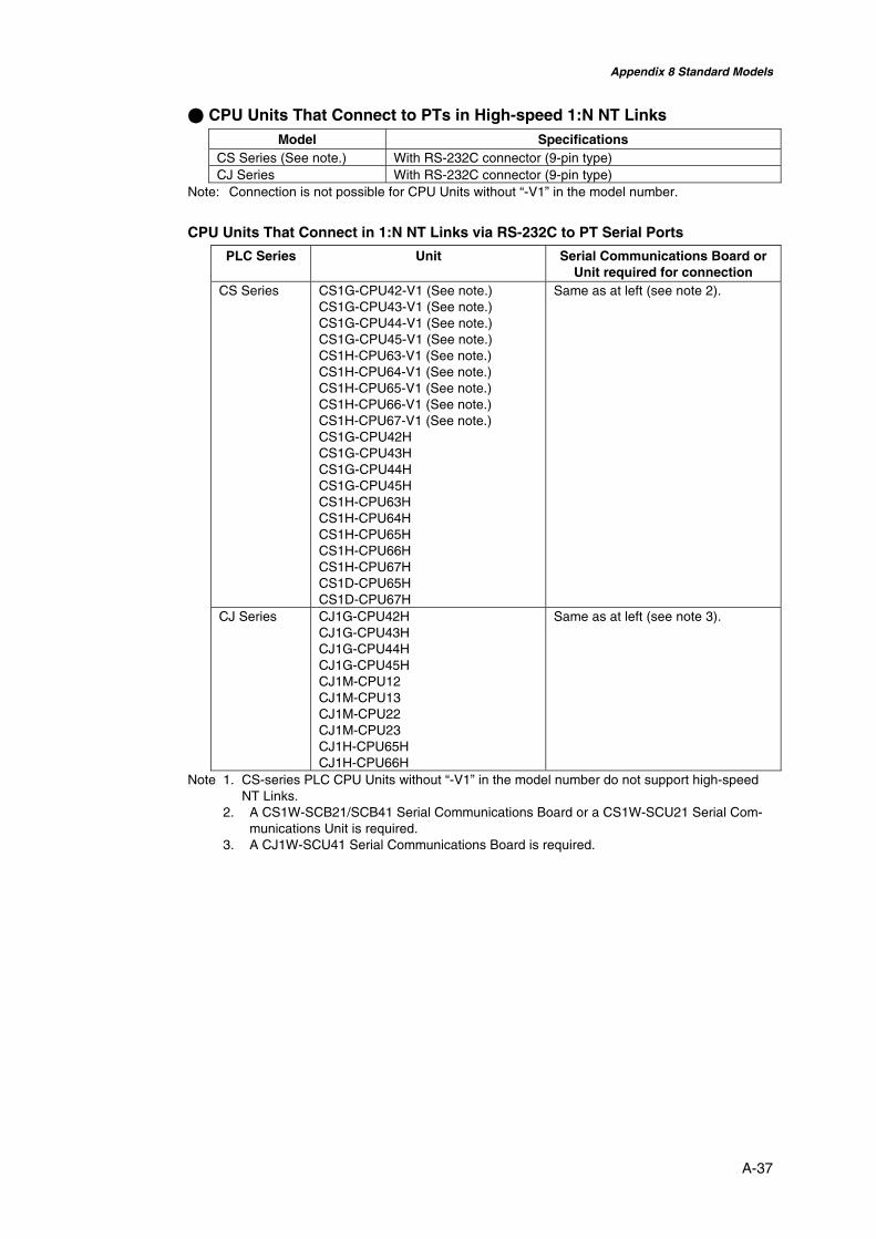
Appendix 8 Standard Models
A-37
@ CPU Units That Connect to PTs in High-speed 1:N NT LinksModel Specifications
CS Series (See note.) With RS-232C connector (9-pin type)CJ Series With RS-232C connector (9-pin type)
Note: Connection is not possible for CPU Units without “-V1” in the model number.
CPU Units That Connect in 1:N NT Links via RS-232C to PT Serial Ports
PLC Series Unit Serial Communications Board orUnit required for connection
CS Series CS1G-CPU42-V1 (See note.)CS1G-CPU43-V1 (See note.)CS1G-CPU44-V1 (See note.)CS1G-CPU45-V1 (See note.)CS1H-CPU63-V1 (See note.)CS1H-CPU64-V1 (See note.)CS1H-CPU65-V1 (See note.)CS1H-CPU66-V1 (See note.)CS1H-CPU67-V1 (See note.)CS1G-CPU42HCS1G-CPU43HCS1G-CPU44HCS1G-CPU45HCS1H-CPU63HCS1H-CPU64HCS1H-CPU65HCS1H-CPU66HCS1H-CPU67HCS1D-CPU65HCS1D-CPU67H
Same as at left (see note 2).
CJ Series CJ1G-CPU42HCJ1G-CPU43HCJ1G-CPU44HCJ1G-CPU45HCJ1M-CPU12CJ1M-CPU13CJ1M-CPU22CJ1M-CPU23CJ1H-CPU65HCJ1H-CPU66H
Same as at left (see note 3).
Note 1. CS-series PLC CPU Units without “-V1” in the model number do not support high-speedNT Links.
2. A CS1W-SCB21/SCB41 Serial Communications Board or a CS1W-SCU21 Serial Com-munications Unit is required.
3. A CJ1W-SCU41 Serial Communications Board is required.
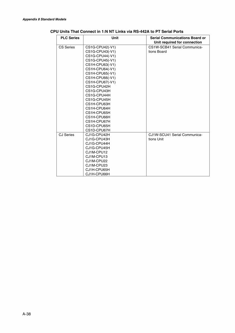
Appendix 8 Standard Models
A-38
CPU Units That Connect in 1:N NT Links via RS-442A to PT Serial Ports
PLC Series Unit Serial Communications Board orUnit required for connection
CS Series CS1G-CPU42(-V1)CS1G-CPU43(-V1)CS1G-CPU44(-V1)CS1G-CPU45(-V1)CS1H-CPU63(-V1)CS1H-CPU64(-V1)CS1H-CPU65(-V1)CS1H-CPU66(-V1)CS1H-CPU67(-V1)CS1G-CPU42HCS1G-CPU43HCS1G-CPU44HCS1G-CPU45HCS1H-CPU63HCS1H-CPU64HCS1H-CPU65HCS1H-CPU66HCS1H-CPU67HCS1D-CPU65HCS1D-CPU67H
CS1W-SCB41 Serial Communica-tions Board
CJ Series CJ1G-CPU42HCJ1G-CPU43HCJ1G-CPU44HCJ1G-CPU45HCJ1M-CPU12CJ1M-CPU13CJ1M-CPU22CJ1M-CPU23CJ1H-CPU65HCJ1H-CPU66H
CJ1W-SCU41 Serial Communica-tions Unit
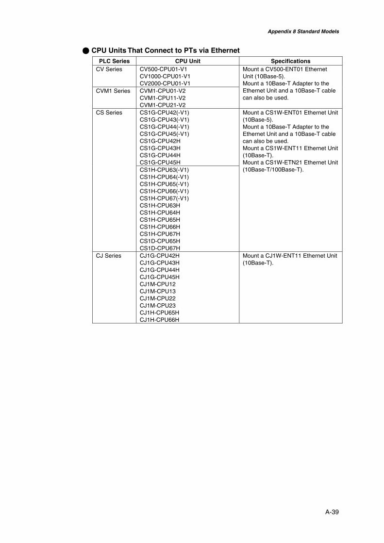
Appendix 8 Standard Models
A-39
@ CPU Units That Connect to PTs via EthernetPLC Series CPU Unit Specifications
CV Series CV500-CPU01-V1CV1000-CPU01-V1CV2000-CPU01-V1
CVM1 Series CVM1-CPU01-V2CVM1-CPU11-V2CVM1-CPU21-V2
Mount a CV500-ENT01 EthernetUnit (10Base-5).Mount a 10Base-T Adapter to theEthernet Unit and a 10Base-T cablecan also be used.
CS1G-CPU42(-V1)CS1G-CPU43(-V1)CS1G-CPU44(-V1)CS1G-CPU45(-V1)CS1G-CPU42HCS1G-CPU43HCS1G-CPU44HCS1G-CPU45H
CS Series
CS1H-CPU63(-V1)CS1H-CPU64(-V1)CS1H-CPU65(-V1)CS1H-CPU66(-V1)CS1H-CPU67(-V1)CS1H-CPU63HCS1H-CPU64HCS1H-CPU65HCS1H-CPU66HCS1H-CPU67HCS1D-CPU65HCS1D-CPU67H
Mount a CS1W-ENT01 Ethernet Unit(10Base-5).Mount a 10Base-T Adapter to theEthernet Unit and a 10Base-T cablecan also be used.Mount a CS1W-ENT11 Ethernet Unit(10Base-T).Mount a CS1W-ETN21 Ethernet Unit(10Base-T/100Base-T).
CJ Series CJ1G-CPU42HCJ1G-CPU43HCJ1G-CPU44HCJ1G-CPU45HCJ1M-CPU12CJ1M-CPU13CJ1M-CPU22CJ1M-CPU23CJ1H-CPU65HCJ1H-CPU66H
Mount a CJ1W-ENT11 Ethernet Unit(10Base-T).

Appendix 8 Standard Models
A-40
CPU Units That Connect to PTs via Controller Link
PLC Series CPU Unit SpecificationsCS Series All CS-series CPU Units Mount a CS1W-CLK21 Controller
Link Unit.CJ Series All CJ-series CPU Units Mount a CJ1W-CLK21 Controller
Link Unit.C200HE/HG/HX Series(See note 1.)
C200HE-CPU32 (-Z)C200HE-CPU42 (-Z)C200HG-CPU33 (-Z)C200HG-CPU43 (-Z)C200HG-CPU53 (-Z)C200HG-CPU63 (-Z)C200HX-CPU34 (-Z)C200HX-CPU44 (-Z)C200HX-CPU54 (-Z)C200HX-CPU64 (-Z)C200HX-CPU65-Z
C200HX-CPU85-Z
Mount a C200HW-CLK21 ControllerLink Unit.
CQM1 Series CQM1H-CPU51CQM1H-CPU61
Mount a CQM1H-CLK21 ControllerLink Unit.
CV Series(See note 2.)
All CV-series CPU Units
CVM1 Series(See note 2.)
All CVM1-series CPU Units
Mount a CVM1-CLK21 ControllerLink Unit.
Note 1. The following are required when mounting a Controller Link Unit:C200HW-COM01/COM04 Communications BoardC200HW-CE001/CE002/CE012 Bus Connection Unit
2. Always set routing tables when using a CVM1/CV-series CPU Unit manufactured in April1996 or earlier. The manufacturing date can be checked with the 4-digit lot number givenon the side of the CPU Unit, as shown below.
The rightmost digit of the year, 1996in this example
.........Manufactured April 199664@@Lot No.:
The month of manufacture1 to 9 = January to SeptemberX to Z = October to December
Refer to the Controller Link Units Operation Manual (W309) for setting methods for thePLC Controller Link Units.
RS-232C/RS-422A Converters
Model SpecificationsNT-AL001 RS-232C: 9-pin connector
RS-422A: 8-pin terminal blockNS-AL002 RS-232C: 9-pin connector
RS-422A: 8-pin terminal blockCJ1W-CIF11 RS-232C: 9-pin connector
RS-422A: 5-pin terminal block
Reference • When a CJ1W-CIF11 Conversion Adapter is used, the total transmission length is50 m.
• If NT-001/NT-002 Link Adapters are used together with CJ1W-CIF11 ConversionAdapters on the same transmission path, the total transmission length is also50 m.

Appendix 8 Standard Models
A-41
Support Tools
Name Model DetailsNS-Designer(See note.)
NS-NSDC1-V@ DOS ComputerFor Windows 95, 98, ME, NT, 2000, or XP(Windows 98, Windows NT Ver. 4.0 Service Pack 3 orlater.)CD-ROM
NS12-KBA04 (Anti-reflection Sheets for NS12/NS10)NS7-KBA04 Anti-reflection Sheets for NS8NT30-KBA04 Anti-reflection Sheets for NS5NS12-KBA05 Protective Cover for NS12 and NS10 (anti-reflection
coating)NS7-KBA05 Protective Cover for NS8 (anti-reflection coating)NT31C-KBA05 Protective Cover for NS5 (anti-reflection coating)NS12-KBA05 N Transparent Protective Cover for NS12 and NS10NS7-KBA05N Transparent Protective Cover for NS8NT31C-KBA05N Transparent Protective Cover for NS5NT30-KBA01 Chemical-resistant Cover for NS5CJ1W-BAT01 Replacement Battery for NS12/NS10/NS8/NS5HMC-EF172 Memory Card (15 Mbytes)HMC-EF372 Memory Card (30 Mbytes)HMC-EF672 Memory Card (64 Mbytes)
Optional products
HMC-AP001 Memory Card Adapter (for connecting Personal Com-puter PC Card Reader/Writer)
Note: The NS-Designer includes a transfer program and standard PT system program.
Reference • NEC PC98-series computers are not supported.
• Use the NEC PC98NX Series, however, in the same way as IBM PC/AT compati-ble computers.
Connecting Cables and Connectors
Cable with Connector (PT-to-PLC)
ModelCablelength
Applicable UnitsCommunications
methodSpecifications
XW2Z-200T 2 m
XW2Z-500T 5 m
Units with 9-pin con-nector and built-in 1:1NT Link function.
NT Link(RS-232C only)
9-pin-to-9-pin
XW2Z-200T-2 2 m
XW2Z-500T-2 5 m
CPM2C peripheralport
NT Link(RS-232C only)
9-pin-to-CPM2Cperipheral port
Cable with Connector (PT-to-Personal Computer)
ModelCablelength
Applicable computer Specifications
XW2Z-S002 2 m DOS and 98NX computers Female 9-pin-to-male 9-pin
Ethernet Cable (PT-to-Personal Computer)
Particular models are not specified, but use a cable that meets the following specifications.
Item SpecificationsConformance standards Conforms to IEEE 802.3 / Ethernet (10/100Base-T).

Appendix 8 Standard Models
A-42
Transmission medium 2 pair Cat 3 UTP 22-26AWG, Cat 5, Cat 5e, Cat 6Transmission distance 100 m (node-to-hub and hub-to-hub)Connector 8-pin modular connector
RS-232C Connecting Cable
Model SpecificationsAWG28 × 5P IFVV-SB Multiconductor shielded cable
Manufactured by Fujikura Densen.CO-MA-VV-SB 5P × 28AWG Multiconductor shielded cable
Manufactured by Hitachi Densen.
Controller Link Communications Cable
Use one of the twisted-pair cables listed below as the communications cable.Model Manufacturer Remarks
Li2Y-FCY2x0.56qmm KROMBERG & SHUBERT, DepartmentKOMTEC
German company
1x2xAWG-20PE+Tr.CUSN+PVC
DRAKA CABLES INDUSTRIAL Spanish company
#9207 BELDEN American companyESVC0.5x2C Bando Densen Co. Japanese company
Applicable Connectors for RS-232C
Name Model SpecificationsXM2A-2501 25-pin type (male)
Manufactured by OMRON.XM2D-2501 25-pin type (female)
Manufactured by OMRON.(for DOS computers)
XM2A-0901 9-pin type (male)Manufactured by OMRON.
XM2D-0901 9-pin type (female)Manufactured by OMRON.(for DOS computers)
Connector
DB-25P 25-pin type (male)Manufactured by JAE.
XM2S-2511 25-pin type, mm screwsManufactured by OMRON.
XM2S-2513 25-pin type, inch screwsManufactured by OMRON.
XM2S-0911 9-pin type, mm screwsManufactured by OMRON.
XM2S-0911-E 9-pin type, mm screwsManufactured by OMRON.
XM2S-0913 9-pin type, inch screwsManufactured by OMRON.
Connector hood
DB-C2-J9 25-pin typeManufactured by JAE.
Cables for CS1-series PLC Peripheral Port
Model SpecificationsCS1W-CN118 Manufactured by OMRON
(CS1-series peripheral port-to-D-Sub female 9-pin connector)

Appendix 9 List of Optional Products
A-43
Appendix 9 List of Optional Products
A-9-1 Anti-reflection Sheets: NS12-KBA04, NS7-KBA04, NT30-KBA04Attached to the display to prevent random reflection and dirt. The sheets are all colorlessand transparent. One set contains five sheets.
RUN
Material Mounting methodPolyester film Double-sided tape
Model SpecificationsNS12-KBA04 Anti-reflection Sheets for NS12/NS10NS7-KBA04 Anti-reflection Sheets for NS8NT30-KBA04 Anti-reflection Sheets for NS5
A-9-2 Protective Covers: NS12-KBA05(N), NS7-KBA05(N), NT31C-KBA05(N)
This cover protects the display surface from oil, dust, and finger marks. One set containsfive covers.
POWERRUN
RUN
Material Mounting methodPolyester film Double-sided tape

Appendix 9 List of Optional Products
A-44
Model SpecificationsNS12-KBA05 Opaque White Protective Cover for NS12 and NS10
(anti-reflection coating)NS7-KBA05 Opaque White Protective Cover for NS8 (anti-
reflection coating)NT31C-KBA05 Opaque White Protective Cover for NS5 (anti-
reflection coating)NS12-KBA05N Transparent Protective Cover for NS12 and NS10NS7-KBA05N Transparent Protective Cover for NS8NT31C-KBA05N Transparent Protective Cover for NS5
A-9-3 NT30-KBA01 Chemical-resistant CoverThis Cover on the front panel protects the Unit from chemicals. The whole sheet is opaquewhite and made from silicon rubber.
Model SpecificationsNT30-KBA01 Chemical-resistant Cover for the NS5-V1
A-9-4 Replacement Battery: CJ1W-BAT01This is a lithium battery for backing up the contents of the memory.
CJ1W-BAT01
Model SpecificationsCJ1W-BAT01 Replacement Battery for NS12-V1/NS10-
V1/NS8-V1/NS5-V1
A-9-5 Recommended Memory Cards:
HMC-EF172, HMC-EF372, and HMC-EF672
A-9-6 Recommended Memory Card Adapter: HMC-AP001The Memory Card is an external memory that can save and read screen data, log data,and system programs between the PT and computer. By using the HMC-AP001, this datacan be exchanged with computers that are connected to PC Cards.The memory capacity depends on the model of the Memory Card used.
Model CapacityHMC-EF172 15 MbytesHMC-EF372 30 MbytesHMC-EF672 64 Mbytes

Appendix 9 List of Optional Products
A-45
A-9-7 NS-CLK21 Controller Link Interface UnitThis Expansion Unit enables Controller Link communications with PLCs and FA comput-ers. It can be mounted to the NS12-TS0@ or NS10-TV0@. It cannot be mounted to theNS8-TV@@ or NS5-SQ0@.
A-9-8 NS-CA001/CA002 Video Input UnitThis Expansion Unit enables displaying video images from video cameras or Vision Sen-sors on the PT.An external analog RGB image can be input with the NS-CA002 and displayed on the PT.Refer to the NS Series RGB/Video Input Unit Operation Manual (Cat. No. V086) for detailson the NS-CA002.It can be mounted to the NS12-TS0@, NS10-TV0@ or NS8-TV@@. The Video Input Unitcannot be mounted to the NS5-SQ0@.
HMC-EF372

Appendix 10 System Memory List
A-46
Appendix 10 System Memory ListSystem memory is used for exchanging information between the host and the PT, such ascontrolling the PT and notifying the host of PT status.The system memory is divided into bit and word sections.
System Bit Memory ($SB)
System bit memory ($SB) is used for exchanging information between the host and the PTin bit units, such as controlling the PT and notifying the host of PT status.The system bit memory contains 52 bits with predefined functions.The system bit memory is listed in the following table.
Address Classification Function$SB0 Notification RUN signal (Pulse)$SB1 Notification RUN signal (Always ON)$SB2 Notification Screen switch strobe$SB3 Control Prohibit Shifting to System Menu$SB4 Notification Battery Low$SB5 Notification Data Input Detector$SB6 Control Brightness adjust, high$SB7 Control Brightness adjust, medium$SB8 Control Brightness adjust, low$SB9 Control Backlight Control (screen saver Control)$SB10 Control Control Backlight Flashing$SB11 Notification Backlight status$SB12 Control Continuous buzzer$SB13 Control Short intermittent buzzer$SB14 Control Long intermittent buzzer$SB15 Notification/control Notification/Control of Video Input$SB16 Control Processing Priority Registration for Port A (NT Link 1:N)$SB17 Control Processing Priority Registration Port B (NT Link 1:N)$SB18 Control Display keypad with temporary input$SB19 Control Prohibit input$SB20 Control Contrast Adjustment (+10 levels) (NS5 Only)$SB21 Control Contrast Adjustment (+1 level) (NS5 Only)$SB22 Control Contrast Adjustment (1 level) (NS5 Only)$SB23 Control Contrast Adjustment (10 levels) (NS5 Only)$SB24 Notification/control Video Capture$SB25 Control Starts Printing/Capture Screen (NS12/NS10/NS8 only)
$SB26 Control Stops Printing
$SB27 Control Test Pattern Printing
$SB28 Control Printer Head Cleaning
$SB29 Control Update Printer Status
$SB30 Notification Printer Busy Status
$SB31 Notification Notification of Printer Error
$SB32 Notification/control Initialize Alarm/Event History$SB33 Notification/control Save Alarm/Event History$SB34 − Reserved$SB35 Notification/control Initialize Data Log$SB36 Notification/control Save Data Log$SB37 Notification/control Initialize Operation Log$SB38 Notification/control Save Operation Log$SB39 Control Log Functional Object Operation$SB40 Control Log Switch Screen Operation

Appendix 10 System Memory List
A-47
Address Classification Function$SB41 Control Log Macro Operation$SB42 Notification/control Initialize Error Log$SB43 Notification/control Save Error Log$SB44 − Reserved$SB45 Control Macro error dialog control$SB46 Notification Notification of Macro Error$SB47 Notification Logging Process or Video Capture Error Flag$SB48 Notification Memory Card Free Space Check Flag$SB49 Notification/control Stop Memory Card$SB50 Notification Memory Card Removing Status$SB51 Notification Periodical Data Log Save in Process Flag
The notification words are not write prohibited. In addition, the system will not restore val-ues, except when the status has changed.
System memory is allocated to PLC areas as shown below.Allocated Addresses for System Memory under NS-Designer Settings/Initialize
$SB + m
15
31
47
0
16
32
Word m: $SB0 to $SB15
Word m+1: $SB16 to $SB31
Word m+2: $SB32 to $SB47
Word m+3: $SB48 to $SB5151 48
System Word Memory ($SW)
System word memory ($SW) is used for exchanging information between the host and thePT in word units, such as controlling the PT and notifying the host of PT status.The system word memory contains 38 items with predefined functions.The system word memory is listed in the following table.
Address Classification Function$SW0 Notification/control Current screen number$SW1 Notification/control Display pop-up screen 1 number$SW2 Notification/control Pop-up screen 1 display position (X coordinate)$SW3 Notification/control Pop-up screen 1 display position (Y coordinate)$SW4 Notification/control Display pop-up screen 2 number$SW5 Notification/control Pop-up screen 2 display position (X coordinate)$SW6 Notification/control Pop-up screen 2 display position (Y coordinate)$SW7 Notification/control Display pop-up screen 3 number$SW8 Notification/control Pop-up screen 3 display position (X coordinate)$SW9 Notification/control Pop-up screen 3 display position (Y coordinate)$SW10 Notification/control Display label number$SW11 Control Destination (0: Printer/1: Memory Card)$SW12 − Reserved$SW13 Control Password number for input prohibit clear$SW14 Notification Current time (min, s)$SW15 Notification Current date and time (day, hour)$SW16 Notification Current date (year, month)$SW17 Notification Current day (day of the week)$SW18 Notification No. of generated alarms and events$SW19 Notification ID number for generated alarms and events

Appendix 10 System Memory List
A-48
Address Classification Function$SW20 Notification ID number for cleared alarms and events$SW21 Notification Alarm/event ID when alarm/event object macro executed$SW22 − Reserved$SW23 Notification Macro execution error number$SW24 Notification Macro error screen number$SW25 Notification Macro error object ID number$SW26 Notification Error macro execution timing$SW27 Control Offset value for index I0$SW28 Control Offset value for index I1$SW29 Control Offset value for index I2$SW30 Control Offset value for index I3$SW31 Control Offset value for index I4$SW32 Control Offset value for index I5$SW33 Control Offset value for index I6$SW34 Control Offset value for index I7$SW35 Control Offset value for index I8$SW36 Control Offset value for index I9$SW37 Notification/control Data Log Group Number
The notification words are not write prohibited. In addition, the system will not restore values,except when the status has changed.
System word memory is allocated to PLC areas as shown below.Allocated Addresses for System Memory under NS-Designer Settings/Initialize
$SW = n
Word n: $SW0
Word n+1: $SW1
Word n+37: SW37
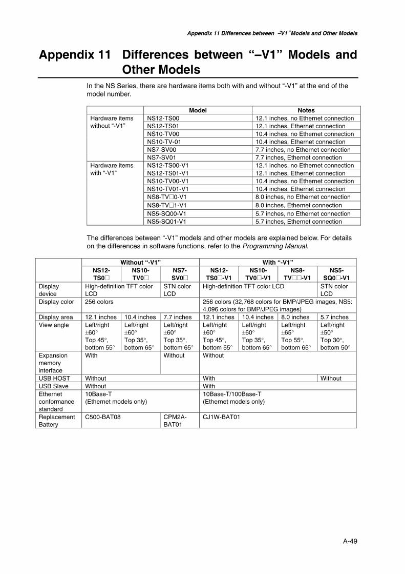
Appendix 11 Differences between “–V1” Models and Other Models
A-49
Appendix 11 Differences between “–V1” Models andOther Models
In the NS Series, there are hardware items both with and without “-V1” at the end of themodel number.
Model NotesNS12-TS00 12.1 inches, no Ethernet connectionNS12-TS01 12.1 inches, Ethernet connectionNS10-TV00 10.4 inches, no Ethernet connectionNS10-TV-01 10.4 inches, Ethernet connectionNS7-SV00 7.7 inches, no Ethernet connection
Hardware itemswithout “-V1”
NS7-SV01 7.7 inches, Ethernet connectionNS12-TS00-V1 12.1 inches, no Ethernet connectionNS12-TS01-V1 12.1 inches, Ethernet connectionNS10-TV00-V1 10.4 inches, no Ethernet connectionNS10-TV01-V1 10.4 inches, Ethernet connectionNS8-TV@0-V1 8.0 inches, no Ethernet connectionNS8-TV@1-V1 8.0 inches, Ethernet connectionNS5-SQ00-V1 5.7 inches, no Ethernet connection
Hardware itemswith “-V1”
NS5-SQ01-V1 5.7 inches, Ethernet connection
The differences between “-V1” models and other models are explained below. For detailson the differences in software functions, refer to the Programming Manual.
Without “-V1” With “-V1”NS12-TS0@
NS10-TV0@
NS7-SV0@
NS12-TS0@-V1
NS10-TV0@-V1
NS8-TV@@-V1
NS5-SQ0@-V1
Displaydevice
High-definition TFT colorLCD
STN colorLCD
High-definition TFT color LCD STN colorLCD
Display color 256 colors 256 colors (32,768 colors for BMP/JPEG images, NS5:4,096 colors for BMP/JPEG images)
Display area 12.1 inches 10.4 inches 7.7 inches 12.1 inches 10.4 inches 8.0 inches 5.7 inchesView angle Left/right
±60°Top 45°,bottom 55°
Left/right±60°Top 35°,bottom 65°
Left/right±60°Top 35°,bottom 65°
Left/right±60°Top 45°,bottom 55°
Left/right±60°Top 35°,bottom 65°
Left/right±65°Top 55°,bottom 65°
Left/right±50°Top 30°,bottom 50°
Expansionmemoryinterface
With Without Without
USB HOST Without With WithoutUSB Slave Without WithEthernetconformancestandard
10Base-T(Ethernet models only)
10Base-T/100Base-T(Ethernet models only)
ReplacementBattery
C500-BAT08 CPM2A-BAT01
CJ1W-BAT01
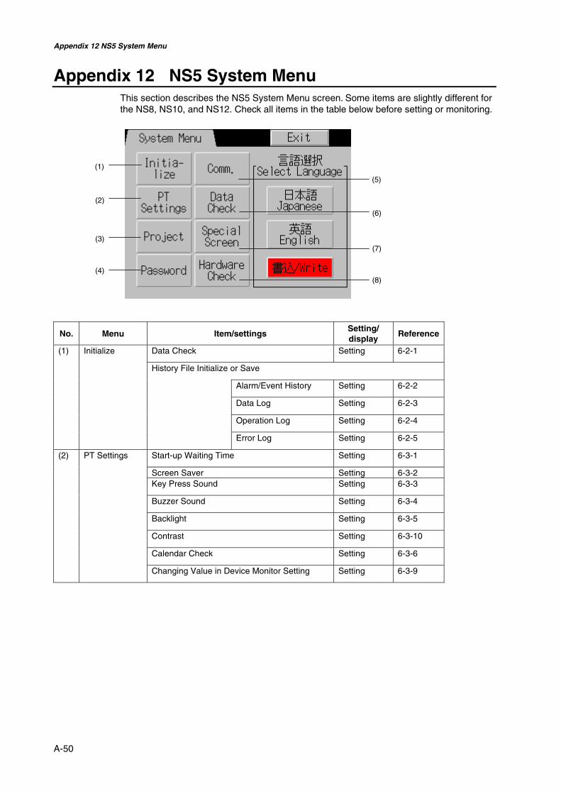
Appendix 12 NS5 System Menu
A-50
Appendix 12 NS5 System MenuThis section describes the NS5 System Menu screen. Some items are slightly different forthe NS8, NS10, and NS12. Check all items in the table below before setting or monitoring.
No. Menu Item/settingsSetting/display
Reference
Data Check Setting 6-2-1
History File Initialize or Save
Alarm/Event History Setting 6-2-2
Data Log Setting 6-2-3
Operation Log Setting 6-2-4
(1) Initialize
Error Log Setting 6-2-5
Start-up Waiting Time Setting 6-3-1
Screen Saver Setting 6-3-2Key Press Sound Setting 6-3-3
Buzzer Sound Setting 6-3-4
Backlight Setting 6-3-5
Contrast Setting 6-3-10
Calendar Check Setting 6-3-6
(2) PT Settings
Changing Value in Device Monitor Setting Setting 6-3-9
(1)
(2)
(3)
(4)
(5)
(6)
(7)
(8)

Appendix 12 NS5 System Menu
A-51
No. Menu Item/settingsSetting/display
Reference
Project Title Display 6-4-1
Number of Labels Display 6-4-2Initial Screen Setting 6-4-3Initial Label Setting 6-4-4History Recording Method
Alarm/Event History Display 6-4-5Data Log Display 6-4-6Operation Log Display 6-4-7Error Log Display 6-4-8
(3) Project
Addresses Allocated to System Memory($SB,$SW)
Display 6-4-9
(4) Password Password Change Setting 6-5Automatic Communications Recovery(Comms. Auto-return)
Setting 6-6-1
Timeout Interval Setting 6-6-1
Retry Count Setting 6-6-1
Serial Port A or B Communications Settings Setting 6-6-1
(5) Comm.
Ethernet Communications Settings Setting 6-6-4
Screen Number Setting 6-7(6) Data CheckShow Address Setting 6-7Error Occurrence/Frequency for All History Files
Alarm History Display 6-8-1Operations Log Display 6-8-2Error Log Display 6-8-3
System Version Display 6-8-9Special Functions
Device Monitor Set-ting/display
6-8-4
Communication Test Setting 6-8-5Video Configuration Setting 6-8-6USB Device List Display 6-8-7Display Capture Data Display 6-8-8Memory Card Transfer Setting 6-8-9
(7) Special Screen
External ApplicationStart-up
Setting 6-8-8
LCD Check Display 6-9-1(8) HardwareCheck
Touch Switch Check Display 6-9-2

Revision History
A manual revision code appears as a suffix to the catalog number on the cover of the manual.
Man.No. V083-E1-03Revision code
The following table outlines the changes made to the manual during each revision. Pagenumbers refer to the previous version.
Revision code Date Revised content01 April 2003 Original production02 October 2003 Added a new section on starting external applications.
Added information throughout the manual to include the NS5-V1.03 July 2004 Changes and corrections for version upgrade.

OMRON CORPORATIONFA Systems Division H.Q.66 MatsumotoMishima-city, Shizuoka 411-8511JapanTel: (81)55-977-9181/Fax: (81)55-977-9045Regional HeadquartersOMRON EUROPE B.V.Wegalaan 67-69, NL-2132 JD HoofddorpThe NetherlandsTel: (31)2356-81-300/Fax: (31)2356-81-388OMRON ELECTRONICS LLC1 East Commerce Drive, Schaumburg, IL 60173U.S.A.Tel: (1)847-843-7900/Fax: (1)847-843-8568OMRON ASIA PACIFIC PTE. LTD.83 Clemenceau Avenue,#11-01, UE Square,Singapore 239920Tel: (65)6835-3011/Fax: (65)6835-2711

Cat. No. V083-E1-03 Note: Specifications subject to change without notice. Printed in Japan
Authorized Distributor:


