NS2 Configuration GuideContentsDescription . . . . . . . . . . . . . . . . . . . . . . . . . . . . . . . . . . . . . . . 1Specifications . . . . . . . . . . . . . . . . . . . . . . . . . . . . . . . . . . . . . 1
Power . . . . . . . . . . . . . . . . . . . . . . . . . . . . . . . . . . . . . . . . 1Backup Battery. . . . . . . . . . . . . . . . . . . . . . . . . . . . . . . . . 1Secondary Backup Battery. . . . . . . . . . . . . . . . . . . . . . . . 1Reader & Aux Power . . . . . . . . . . . . . . . . . . . . . . . . . . . . 1Reader Wiring . . . . . . . . . . . . . . . . . . . . . . . . . . . . . . . . . 2Supervised Input Wiring . . . . . . . . . . . . . . . . . . . . . . . . . 2Inputs . . . . . . . . . . . . . . . . . . . . . . . . . . . . . . . . . . . . . . . . 2Outputs . . . . . . . . . . . . . . . . . . . . . . . . . . . . . . . . . . . . . . . 3Enclosure Specifications . . . . . . . . . . . . . . . . . . . . . . . . . 4Communications & Wiring . . . . . . . . . . . . . . . . . . . . . . . 4DIP Switch Settings . . . . . . . . . . . . . . . . . . . . . . . . . . . . . 5Connection Schematic . . . . . . . . . . . . . . . . . . . . . . . . . . . 6
Configuration Diagrams . . . . . . . . . . . . . . . . . . . . . . . . . . . . . 7RS-232 Connection . . . . . . . . . . . . . . . . . . . . . . . . . . . . . 7RS-485 Connection . . . . . . . . . . . . . . . . . . . . . . . . . . . . . 8NSLAN1 Connection. . . . . . . . . . . . . . . . . . . . . . . . . . . . 9LANSRL100 Connection. . . . . . . . . . . . . . . . . . . . . . . . 10LANSRLU1 Connection . . . . . . . . . . . . . . . . . . . . . . . . 11Lease Line Modem Connection . . . . . . . . . . . . . . . . . . . 12RS-485 Short Haul Modem Connection . . . . . . . . . . . . 13RS-232 Short Haul Modem Connection . . . . . . . . . . . . 14M-9600 Dial-up Modem, RS-485 Connection . . . . . . . 15M-56K Dial-up Modem, RS-485 Connection . . . . . . . . 16Fiber Converter to RS-485 Connection . . . . . . . . . . . . . 17485-PCI/NS2 Panel Connection Detail . . . . . . . . . . . . . 18
Frequently Asked Questions . . . . . . . . . . . . . . . . . . . . . . . . . . . . 19
DescriptionThe NS2 is a two reader panel providing access control for up to two doors through the use of Wiegand readers.
The NS2 may be used as a standalone panel with independent card and transaction storage or, with a software upgrade, as a fully monitored online access control device. Communication to the front-end computer is achieved through an RS-232 serial cable (included with installation kit) or an optional RS-485 interface. Each RS-485 interface is capable of communicating with up to 31 panels.
The NS2 is designed for tile mount using the ENC10 enclo-sure. The I/O terminals are organized by operational utility with connectors for power and RS-485 communications located on the lower right followed from right to left by the relays, auxiliary power, door control inputs, and readers. The Tamper and External Power Fail terminal are located at the left edge above the main line of connectors.
Specifications
PowerAC Non-Polarized:
16.5 VAC utilizing a UL-listed 50 VA Class 2 transformer (TB9-4 AC+/TB9-5 AC–)
or
DC Polarized:
24 VDC, 1.25 Amp (TB9-4 DC+/TB9-5 DC–)
Power WireTwo-wire, 18 AWG, shielded cable.
Backup BatteryCasil 12 VDC (NCI Part #: BAT-3) 4Ah, sealed acid/lead backup battery (J6 DC+/J7 DC–)
Backup battery will provide 2.5 hours of standby backup power.
Charging voltage: 13.7 +/– 0.1 VDC
NOTE: The NS2 panel has deep discharge protection built in for the protection of the battery and will only utilize a backup battery down to 10.2 VDC before the NS2 shuts down. Backup battery should be replaced 2 to 2.5 years: more often if panel has a high rate of backup use.
Secondary Backup BatteryThe NS2 panel memory is backed up using a super capacitor for one week in the absence of power or a backup battery. The super capacitor will backup panel memory and real-time clock and does not require maintenance or replacement.
Reader & Aux PowerReader and AUX power is supplied at 10.8-12.7 VDC with a maximum current of 600 mA.
Five volt (5 VDC) readers require five-volt regulators (North-ern part no. 5VRDREG)
Maximum draw is less then 600 mA: (Reader 1+ Reader 2 + Aux Power) < 600 mA.
NOTE: Aux power must not be used to power locks.
7-101004-01 1
NS2 Configuration Guide Honeywell Access Systems
Reader WiringEach reader port supports a single 12-volt reader with Wiegand output format.
NS2 version 1.01.01 - 1.03.09 supports only the defaulted Wie-gand formats:
F=PN 1 26 S 1 D 1 B1 B2 B3 B4F=PN 2 32 S 0 D 0 B1 B2 B3 B4F=PN 3 34 S 1 D 1 B1 B2 B3 B4
NOTE: NS2 version 1.01.01 - 1.02.04 at this time does not support the ABA card format, the OL, OJ, and OH Options, Anti- Passback and Lock Down Time.
NOTE: NS2 version 1.03.09 does not support the ABA card format or the Lock Down Time option, but does support the NS2MEM mod-ule, the OL, OJ, and OH Options, as well as Anti-Passback (In card only mode).
Supervised Input Wiring
The NS2 supervises inputs 1 through 8 and may be configured for supervised or non-supervised normally open or normally closed contacts. Use standard 1K ohm 5% resistors for supervi-sion.
All eight inputs are assigned default features but can be changed for other configurations as needed.
InputsThe NS2 has 8 input points located on the following terminals:
NOTE: Tamper and External Power Fail are supervised and capa-ble of being used as additional inputs if the default functionality is not needed.
NOTE: The wire used for the inputs should be shielded and cannot exceed 30 ohms over the entire length of the cable. Remember that the distance from the panel to the door must be doubled to determine the total resistance.
Reader 1 Terminal Wire Color Wiegrand Reader
TB3-1 Brown LED Control
TB3-2 Green Data 0 Signal
TB3-3 White Data 1 Signal
TB3-4 Black Common
TB3-5 Red 12VDC Power
TB3-6 Variable Tamper
Reader 2 Terminal Wire Color Wiegrand Reader
TB4-1 Brown LED Control
TB4-2 Green Data 0 Signal
TB4-3 White Data 1 Signal
TB4-4 Black Common
TB4-5 Red 12VDC Power
TB4-6 Variable TamperInput
Terminal Description Input/AuxNumber
TB5-1 Door 1 Rex 1
TB5-3 Door 1 Status 2
TB5-2 Door 1 & 2 Common 1 & 2
TB5-4 Door 2 Rex 3
TB5-6 Door 2 Status 4
TB5-5 Input 3 & 4 Common 3 & 4
TB3-6 Reader Tamper or Aux Input 5 5
TB3-5 Common (Input 5 Common) 5
TB4-6 Reader Tamper or Aux Input 6 6
TB4-4 Common (Input 6 Common) 6
TB1-3 Power Fail or Aux Input 7 7
TB1-1 Enclosure Tamper or Aux Input 8 8
TB1-2 Common (Input 7 & 8 Common) 7 & 8
2 7-101004-01
Honeywell Access Systems NS2 Configuration Guide
OutputsFour form-C relays SPDT (Single Poll Double Throw) gold-contact relays are provided for controlling door locks or other output devices (I.E. sounder, burg panel, phone dialer....etc.).
The energized or ON time for each relay can be configured by using either time zone control, or programmable pulse time via the host software.
Relay 1 is defaulted to control the Door 1 lock & Relay 2 is defaulted for the Door 2 lock. Relay 3 & 4 are used as auxiliary relays for signaling other devices. All 4 relays are rated at 12 Amps / 28VDC for resistive loads and 6 Amps / 28VDC for inductive loads (data switching). NOTE: Once the relay pole has been used for an inductive load (including door strikes and magnetic locks) it should not be used for low current dry circuit applications.
NOTE: Switching of inductive loads can cause EMI (Electromag-netic Interference) which may interfere with the normal operation of other equipment.
To minimize premature contact failure and increase system reliability, contact circuit protection such as the S-4 suppressor is required. Locate this device as close as possible to the Door Strike / Maglock.
OutputTerminal Description Relay/Output
Number
TB7-1 Normally Open (NO) Relay 1 (Door 1)
TB7-2 Common (COM) Relay 1 (Door 1)
TB7-3 Normally Closed (NC) Relay 1 (Door 1)
TB7-4 Normally Open (NO) Relay 2 (Door 2)
TB7-5 Common (COM) Relay 2 (Door 2)
TB7-6 Normally Closed (NC) Relay 2 (Door 2)
TB8-1 Normally Open (NO) Relay 3
TB8-2 Common (COM) Relay 3
TB8-3 Normally Closed (NC) Relay 3
TB8-4 Normally Open (NO) Relay 4
TB8-5 Common (COM) Relay 4
TB8-6 Normally Closed (NC) Relay 4
7-101004-01 3
NS2 Configuration Guide Honeywell Access Systems
Enclosure Specifications
Communications & Wiring
NOTE: The C-100-A1/A2 (RS-232 communication loop), M-200 (1,200 Baud rate dial up modem), M-300-LO/LA (1,200 Baud Leased line modem), F210D (Fiber to RS-232) [Discontinued] and F290D (Fiber to RS-485) [Discontinued] are not supported with the NS2 panel(s).
Mounting
One NS2 panel in a standard 19-inch, high density enclosure. Up to eight NS2 panels in a single 19-inch rack mountable enclosure
Dimensions
Board 9-inch Length x 5.5-inch Wide x 1-inch High
Enclosure 12.5-inch Wide x 14.5-inch High x 3.5-inch Deep
Environmental
Temperature 35–110° F operational
Humidity 0–85% RHNC
Communication Type Description Maximum Panels Maximum DistanceFeet / Meters
Direct to COM Port
CBL50, RS-232 Cable 9-pin to RJ-45 1 50 15.25
N-485-PCI-2 RS-485 9-pin to CPU 31 4K 1219.5
Network
NSLAN1 Cobox Unit (RS-232) 1 NS2 panel per NSLAN164 max IP connections per system 328 100
LANSRL100/N-485-PCI-2L Ethernet to RS-485 31 NS2 panels per 485 interface64 max IP connections per system 328/4K 100/1219.6
LANSRLU1/N-485-PCI-2L Ethernet to RS-485 31 NS2 panels per 485 interface64 max IP connections per system 328/4K 100/1219.6
Modems
M-9600-LA (LO)/N-485-PCI Lease-line Modem to RS-485 31 NA/4K NA/1219.6
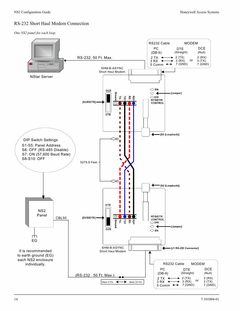
SHM-B-ASYNC/N-485-PCI Short-haul Modem to RS-485 31 5279.9/4K 1609.84/1219.6
SHM-B-ASYNC/CBL50 Short-haul Modem to RS-232 1 5279.9/50 1609.84/15.25
M-9600-2/N-485-HUB-2 Dial-up Modem to RS-485 31 NA/4K NA/1219.6
M-56/N-485-HUB-2 Dial-up Modem to RS-485 31 NA/4K NA/1219.6
Fiber
FC485 Fiber converter to RS-485 31 10K/4K 3049/1219.6
Cable Specifications Description AWG Maximum DistanceFeet / Meters
Readers
NC1861-BL 6 Conductor, Shielded 18 500 152.5
Alarm Input
NC1821-GR Twisted Pair, Shielded 18 2K 609.8
Relay Outputs
NC1821-GR Twisted Pair, Shielded 18 2K 609.8
4 7-101004-01
Honeywell Access Systems NS2 Configuration Guide
DIP Switch Settings
S1 S2 S3 S4 S5 S6 S7 S8 S9 S10 SELECTION
OFF OFF OFF OFF OFF Address 0
ON OFF OFF OFF OFF Address 1(default)
OFF ON OFF OFF OFF Address 2
ON ON OFF OFF OFF Address 3
OFF OFF ON OFF OFF Address 4
ON OFF ON OFF OFF Address 5
OFF ON ON OFF OFF Address 6
ON ON ON OFF OFF Address 7
OFF OFF OFF ON OFF Address 8
ON OFF OFF ON OFF Address 9
OFF ON OFF ON OFF Address 10
ON ON OFF ON OFF Address 11
OFF OFF ON ON OFF Address 12
ON OFF ON ON OFF Address 13
OFF ON ON ON OFF Address 14
ON ON ON ON OFF Address 15
OFF OFF OFF OFF ON Address 16
ON OFF OFF OFF ON Address 17
OFF ON OFF OFF ON Address 18
ON ON OFF OFF ON Address 19
OFF OFF ON OFF ON Address 20
ON OFF ON OFF ON Address 21
OFF ON ON OFF ON Address 22
ON ON ON OFF ON Address 23
OFF OFF OFF ON ON Address 24
ON OFF OFF ON ON Address 25
OFF ON OFF ON ON Address 26
ON ON OFF ON ON Address 27
OFF OFF ON ON ON Address 28
ON OFF OFF ON ON Address 29
OFF ON ON ON ON Address 30
ON ON ON ON ON Address 31
OFF RS-232 (default)
ON RS-485 PCI Interface
OFF 19200 Baud (RS-232 only)
ON 57600 Baud (RS-232 only, default)
OFF OFF RS-485 Bias Off (default)
ON ON RS-485 Bias On
OFF RS-485 EOL Off
ON RS-485 EOL On
7-101004-01 5
NS2 Configuration Guide Honeywell Access Systems
Connection Schematic
1 ON
10
RESERVEDRESERVEDRESERVEDRESERVED
LEDDATA 0DATA 1
+12VDCRDR TMPR/AUX 6
DR1 REXCOMMON
DR1 STATUSDR2 REX
COMMONDR2 STATUS
AUX +12VDCAUX COM
RELAY1 NORELAY1 COMRELAY1 NCRELAY2 NORELAY2 COMRELAY2 NC
RELAY3 NORELAY3 COMRELAY3 NCRELAY4 NORELAY4 COMRELAY4 NC
RS485 +RS485 -RS485 COMAC/DC +AC/DC -
LEDDATA 0DATA 1
+12VDCRDR TMPR/AUX 5
ENC
TMPR
/AU
X 8CO
MM
ON
PWR
FAI
L/AU
X 7
BROWNGREENWHITEBLACKREDVARIES
PWR ON LEDPWR ON LED
RE
AD
ER
1R
EA
DE
R2
TB1
TB2
TB3
TB4
TB5
TB6
TB9
TB8
TB7
RELAY LEDS
SYSTEM STATUSLEDS
POWER LED
DIPSWITCHES
INPUT 1
INPUT 2INPUT 3
INPUT 4
RELAY1
RELAY2
RELAY3
RELAY4
J6 (DC+)J7 (DC-)
PF
RUN
C1
C2
1
2
3
4
BATTERY
COMMON
COMMONOPTIONALETHERNETINTERFACE
RS-232PORT
X PORT
6 7-101004-01
Honeywell Access Systems NS2 Configuration Guide
Configuration Diagrams
RS-232 Connection
One NS2 panel for each COM port.
DIP Switch Settings S1-S5: Panel Address S6: OFF (RS-485 Disable) S7: ON (57,600 Baud Rate) S8-S10: OFF
NStar Server
COM 1
COM 2
NS2Panel
EG
NS2Panel
CBL50(RS-232)50 ft. Max.
CBL50 (RS-232) 50 ft. Max.
Request To Send (RTS)
CBL50 (RS-232)
Signal Ground (GND)
Receive Data (RXD)
Transmit Data (TXD)
Clear To Send (CTS)
RS-232(DB9) RJ-45
8
5
2
3
7
2
3
4
5
7 9-Pin COM 1 or COM 2 to RJ-45 on NS2 Panel
EGIt is recommended to earth ground (EG)each NS2 enclosure individually.
7-101004-01 7
NS2 Configuration Guide Honeywell Access Systems
RS-485 Connection
Thirty-one NS2 panels for each drop line.
NStar Server
COM Port RS-232 (50 Ft. Max.)
N-485-PCI-2
RS-485 (4,000 Ft.)
Refer to 485-PCI / NS2 PanelConnection
Detail diagram.
NS2Panel
NS2Panel
Only Earth Groundone side of cable.
It is recommended to earth ground (EG)each NS2 enclosure individually.
DIP Switch SettingsS1-S5: Panel AddressS6: ON (RS-485 Enable)S7: N/A (Baud Rate)S8-S9: OFF (Bias)S10: OFF (485 EOL)
EG
EGEG
EG
DIP Switch SettingsS1: ONS2: ONS3: ONS4: ONS5: ONS6: OFF (Ack/Nak on)S7: ONS8: OFF (19,200 Baud Rate)
DIP Switch SettingsS1-S5: Panel AddressS6: ON (RS-485 Enable)S7: N/A (Baud Rate)S8-S9: OFF (Bias)S10: ON (485 EOL)
4,000 ft. (1,200 m) max, 24 AWG, 2 twisted pairs withshield, 120 ohm, 23 pf (NCI part no. NCP2441-TN)
RS-485Red/WhiteBlack/GreenRS-485 COM
NS2 PanelTB9-1 (RS485+)TB9-2 (RS485-)TB9-3 (RS485 COM)
RS-485 Cable
See RS-485Cable note.
8 7-101004-01
Honeywell Access Systems NS2 Configuration Guide
NSLAN1 Connection
One NSLAN1 for each NS2 panel, Maximum sixty-four IP connections.
NStar Server
100BaseT (CAT 5) 328 Ft. Max.
EG
NSLAN1 must beprogrammed with a
static IP addressSee NSLAN1 product
documentation forprograming instructions.
DIP Switch SettingsS1-S5: Panel AddressS6: OFF (RS-485 Disable)S7: ON (57,600 Baud Rate)S8-S10: OFF
HUB
It is recommended to earth ground(EG) each NS2 enclosure individually.
EG
NIC
NS2Panel
NSLAN1installed
NS2Panel
NSLAN1installed
7-101004-01 9
NS2 Configuration Guide Honeywell Access Systems
LANSRL100 Connection
Thirty-one NS2 panels for each drop line, Maximum sixty-four IP connections.
NStar Server HUB
100BaseT (CAT 5) 328 Ft. Max.
RJ-45
LANSRL100
Refer toLANSRL100
documentationfor programmig.
NS2Panel
NS2Panel
N-485-PCI-2L
100BaseT (CAT 5)328 Ft. Max.
EG
NIC
RS-232 (50 Ft.)
Refer to485-PCI /
NS2 PanelConnection
Detaildiagram.
DIP Switch Settings
Only Earth Ground(EG) one side of
cable.EG EG
EG
It is recommended to earth ground (EG) eachNS2 enclosure individually.
DIP Switch SettingsS1-S5: Panel AddressS6: ON (RS-485 Enable)S7: N/A (Baud Rate)S8-S9: OFF (Bias)S10: ON (485 EOL)
DIP Switch SettingsS1-S5: Panel AddressS6: ON (RS-485 Enable)S7: N/A (Baud Rate)S8-S9: OFF (Bias)S10: OFF (485 EOL)
S1: ONS2: ONS3: ONS4: ONS5: ONS6: OFF (Ack/Nak on)S7: ONS8: OFF (19,200 Baud Rate)
4,000 ft. (1,200 m) max, 24 AWG, 2 twisted pairs withshield, 120 ohm, 23 pf (NCI part no. NCP2441-TN)
RS-485Red/WhiteBlack/GreenRS-485 COM
NS2 PanelTB9-1 (RS485+)TB9-2 (RS485-)TB9-3 (RS485 COM)
RS-485 Cable
See RS-485Cable note.
10 7-101004-01
Honeywell Access Systems NS2 Configuration Guide
LANSRLU1 Connection
Thirty-one panels for each drop line, Maximum sixty-four IP connections.
NStar Server HUB
100BaseT (CAT 5) 328 Ft. Max.
RJ-45
LANSRLU1
Refer to LANSRLU1
documentationfor programmig. N-485-PCI-2L
100BaseT (CAT 5)328 Ft. Max.
NIC
RS-232 (50 Ft.)
Refer to485-PCI /NS2 PanelConnection
Detaildiagram.
DIP Switch SettingsS1: ONS2: ONS3: ONS4: ONS5: ONS6: OFF (Ack/Nak on)S7: ONS8: OFF (19,200 Baud Rate)
NS2Panel
NS2Panel
EGOnly Earth Ground (EG)
one side of cable.EG EG
EG
It is recommended to earth ground (EG) eachNS2 enclosure individually.
DIP Switch SettingsS1-S5: Panel AddressS6: ON (RS-485 Enable)S7: N/A (Baud Rate)S8-S9: OFF (Bias)S10: ON (485 EOL)
DIP Switch SettingsS1-S5: Panel AddressS6: ON (RS-485 Enable)S7: N/A (Baud Rate)S8-S9: OFF (Bias)S10: OFF (485 EOL)
4,000 ft. (1,200 m) max, 24 AWG, 2 twisted pairs withshield, 120 ohm, 23 pf (NCI part no. NCP2441-TN)
RS-485Red/WhiteBlack/GreenRS-485 COM
NS2 PanelTB9-1 (RS485+)TB9-2 (RS485-)TB9-3 (RS485 COM)
RS-485 Cable
See RS-485Cable note.
7-101004-01 11
NS2 Configuration Guide Honeywell Access Systems
Lease Line Modem Connection
Thirty-one NS2 panels for each drop line.
NStar Server
M-9600-LA
Straight Thru Cable (9-25 Pin)
M-9600-LO
LeaseLinePhoneLine
RS-485 (4,000 Ft.)
N-485-PCI-2
RS-232 (50 Ft.)
Female Male
DB 9 / DB 25 Connectors
Refer to485-PCI /
NS2 PanelConnection
Detaildiagram.
DIP Switch SettingsS1: ONS2: ONS3: ONS4: ONS5: ONS6: OFF (Ack/Nak on)S7: ONS8: OFF (19,200 Baud Rate)
NS2Panel
NS2Panel
Only Earth Ground (EG)one side of cable.
EG EG
EG EG
DIP Switch SettingsS1-S5: Panel AddressS6: ON (RS-485 Enable)S7: N/A (Baud Rate)S8-S9: OFF (Bias)S10: ON (485 EOL)
DIP Switch SettingsS1-S5: Panel AddressS6: ON (RS-485 Enable)S7: N/A (Baud Rate)S8-S9: OFF (Bias)S10: OFF (485 EOL)
It is recommended to earth ground (EG) eachNS2 enclosure individually.
Female 9 Pin Male 25 Pin
(TX) 3 2 (TX)(Comm) 5 7 (Comm)
(RX) 2 3 (RX)
RS-232 (50 Ft.)
COM Port
Null Modem Cable Cable (9-25 Pin)Male 9 Pin Female 25 Pin
(TX) 3 3 (RX)(Comm) 5 7 (Comm)
(RX) 2 2 (TX)
4,000 ft. (1,200 m) max, 24 AWG, 2 twisted pairs withshield, 120 ohm, 23 pf (NCI part no. NCP2441-TN)
RS-485Red/WhiteBlack/GreenRS-485 COM
NS2 PanelTB9-1 (RS485+)TB9-2 (RS485-)TB9-3 (RS485 COM)
RS-485 Cable
See RS-485Cable note.
12 7-101004-01
Honeywell Access Systems NS2 Configuration Guide
RS-485 Short Haul Modem Connection
Thirty-one NS2 panels for each drop line.
EG
NS2Panel
NS2Panel
NStar Server
RS-232, 50 Ft. Max.
RS-232, 50 Ft. Max.
N-485-PCI-2
DIP Switch SettingsS1-S5: Panel AddressS6: ON (RS-485 Enable)S7: N/A (Baud Rate)S8-S9: OFF (Bias)S10: ON (485 EOL)
DIP Switch SettingsS1-S5: Panel AddressS6: ON (RS-485 Enable)S7: N/A (Baud Rate)S8-S9: OFF (Bias)S10: OFF (485 EOL)
DIP Switch SettingsS1: ONS2: ONS3: ONS4: ONS5: ONS6: OFF (Ack/Nak on)S7: ONS8: OFF (19,200 Baud Rate)
It is recommended to earth ground (EG)each NS2 Enclosure individually.
Only Earth Ground (EG)one side of cable. EGEG
EG
Refer to 485-PCI/NS2Panel Connection
Detail diagram.
RS232 Cable
2 TX3 RX
DTE(Straight)
2 (TX)3 (RX)
7 (GND)
DCE(Null)2 (RX)3 (TX)
7 (GND)
PC(DB-9)
MODEM
5 Commor
RS232 Cable
2 TX3 RX
DTE(Straight)
2 (TX)3 (RX)
7 (GND)
DCE(Null)2 (RX)3 (TX)
7 (GND)
PC(DB-9)
MODEM
5 Commor
Male 9 Pin Male 25 Pin
5279.9 Feet
SHM-B-ASYNCShort Haul Modem
4,000 ft. (1,200 m) max, 24 AWG, 2 twisted pairs withshield, 120 ohm, 23 pf (NCI part no. NCP2441-TN)
RS-485Red/WhiteBlack/GreenRS-485 COM
NS2 PanelTB9-1 (RS485+)TB9-2 (RS485-)TB9-3 (RS485 COM)
RS-485 Cable
See RS-485Cable note.
7-101004-01 13
NS2 Configuration Guide Honeywell Access Systems
RS-232 Short Haul Modem Connection
One NS2 panel for each loop.
NStar Server
RS-232, 50 Ft. Max.
5279.9 Feet
NS2Panel
EG
DIP Switch SettingsS1-S5: Panel AddressS6: OFF (RS-485 Disable)S7: ON (57,600 Baud Rate)S8-S10: OFF
It is recommendedto earth ground (EG)each NS2 enclosure
individually.
SHM-B-ASYNCShort Haul Modem
Male 9 Pin Male 25 Pin
(RS-232 50 Ft. Max.)
RS232 Cable
2 TX3 RX
DTE(Straight)
2 (TX)3 (RX)
7 (GND)
DCE(Null)2 (RX)3 (TX)
7 (GND)
PC(DB-9)
MODEM
5 Commor
RS232 Cable
2 TX3 RX
DTE(Straight)
2 (TX)3 (RX)
7 (GND)
DCE(Null)2 (RX)3 (TX)
7 (GND)
PC(DB-9)
MODEM
5 Commor
CBL50
14 7-101004-01
Honeywell Access Systems NS2 Configuration Guide
M-9600 Dial-up Modem, RS-485 Connection
Thirty-one NS2 panels for each drop line.
NStar Server
M-9600-2
N-485-HUB-2
M-9600-2
Dedicated analog phoneline recommended
Analog Phone Line
NS2Panel
NS2Panel
RS-485 (4,000 Ft.)
Straight Thru Cable (9-25 Pin)
RS-232 (50 Ft.)Refer to485-PCI /
NS2 PanelConnection
Detaildiagram.
Only Earth Ground (EG)one side of cable.
EG EG
EG EG
It is recommended to earth ground (EG) eachNS2 enclosure individually.
DIP Switch SettingsS1: ONS2: ONS3: ONS4: ONS5: ONS6: OFF (Ack/Nak on)S7: ONS8: OFF (19,200 Baud Rate)
Female 9 Pin Male 25 Pin
(TX) 3 2 (TX)(Comm) 5 7 (Comm)
(RX) 2 3 (RX)
Female Male
DB 9 / DB 25 Connectors
DIP Switch SettingsS1-S5: Panel AddressS6: ON (RS-485 Enable)S7: N/A (Baud Rate)S8-S9: OFF (Bias)S10: ON (485 EOL)
DIP Switch SettingsS1-S5: Panel AddressS6: ON (RS-485 Enable)S7: N/A (Baud Rate)S8-S9: OFF (Bias)S10: OFF (485 EOL)
4,000 ft. (1,200 m) max, 24 AWG, 2 twisted pairs withshield, 120 ohm, 23 pf (NCI part no. NCP2441-TN)
RS-485Red/WhiteBlack/GreenRS-485 COM
NS2 PanelTB9-1 (RS485+)TB9-2 (RS485-)TB9-3 (RS485 COM)
RS-485 Cable
See RS-485Cable note.
7-101004-01 15
NS2 Configuration Guide Honeywell Access Systems
M-56K Dial-up Modem, RS-485 Connection
Thirty-one NS2 panels for each drop line.
NStar Server
M-56K
M-56K
FAX/MODEM
FAX/MODEM
Local DIP Switch Settings(1, 3, 5, 8 ON) (2, 4, 6, 7 OFF)
Remote DIP Switch Settings(1, 3, 8 ON) (2, 4, 5, 6, 7 OFF)
N-485-HUB-2
NS2Panel
NS2Panel
Refer to485-PCI/
NS2 PanelConnection
Detaildiagram.
Dedicated analog phoneline recommended
Analog Phone Line
RS-485 (4,000 Ft.)
RS-232 (50 Ft.)
It is recommended to earth ground (EG)each NS2 Enclosure individually.
Only Earth Ground (EG)one side of cable.
EG EG
EG EG
DIP Switch SettingsS1-S5: Panel AddressS6: ON (RS-485 Enable)S7: N/A (Baud Rate)S8-S9: OFF (Bias)S10: ON (485 EOL)
DIP Switch SettingsS1-S5: Panel AddressS6: ON (RS-485 Enable)S7: N/A (Baud Rate)S8-S9: OFF (Bias)S10: OFF (485 EOL)
DIP Switch SettingsS1: ONS2: ONS3: ONS4: ONS5: ONS6: OFF (Ack/Nak on)S7: ONS8: OFF (19,200 Baud Rate)
Female 9 Pin Male 25 Pin
(TX) 3 2 (TX)(Comm) 5 7 (Comm)
(RX) 2 3 (RX)
Straight Thru CableCOM Port
4,000 ft. (1,200 m) max, 24 AWG, 2 twisted pairs withshield, 120 ohm, 23 pf (NCI part no. NCP2441-TN)
RS-485Red/WhiteBlack/GreenRS-485 COM
NS2 PanelTB9-1 (RS485+)TB9-2 (RS485-)TB9-3 (RS485 COM)
RS-485 Cable
See RS-485Cable note.
Female Male
DB 9 / DB 25 Connectors
16 7-101004-01
Honeywell Access Systems NS2 Configuration Guide
Fiber Converter to RS-485 Connection
Thirty-one NS2 panels for each drop line.
NStar ServerN-485-PCI-2
NS2Panel
Fiber Wire10,000 Ft.
COM Port RS-232 (50 Ft. Max.)
EG
EG
EG
EG
EG
EG
Refer to 485-PCI/NS2 PanelConnection Detail diagram.
S1: ONS2: ONS3: ONS4: ONS5: ONS6: OFF (Ack/Nak)S7: ONS8: OFF (19,200 Baud Rate)
DIP Switch Settings
DIP Switch SettingsS1-S5: Panel AddressS6: ON (RS-485 Enable)S7: N/A (Baud Rate)S8-S9: OFF (Bias)S10: ON (485 EOL)
DIP Switch SettingsS1-S5: Panel AddressS6: ON (RS-485 Enable)S7: N/A (Baud Rate)S8-S9: OFF (Bias)S10: OFF (485 EOL)
RS-485 (4000 Ft. Max.)
It is recommended toearth ground (EG)
each NS2 enclosureindividually.
RS-485 Comm.
RXDPWRTXD
RS-485 Positive(+)
RS-485 Negitive (-)
Fiber TXD
Fiber RXD
FC485RS-485 Fiber Converter
TB9-1 (RS485 +)
TB9-2 (RS485 -)
NS2 Panel
RS-485 Drain Wire Floating
TB9-3 (RS485 Comm)
Fiber Wire10,000 Ft.
TB9-1 (RS485 +)
TB9-2 (RS485 -)
TB9-3 (RS485 Comm)NS2 Panel
RS-485 Drainnot connected here(connected at panel side)
RS-485 Comm.
RXDPWRTXD
RS-485 Positive(+)
RS-485 Negitive (-)
Fiber TXD
Fiber RXD
FC485RS-485 Fiber Converter
NS2Panel
NS2Panel
RS-485 Comm.
RXDPWRTXD
RS-485 Positive(+)
RS-485 Negitive (-)
Fiber TXD
Fiber RXD
FC485RS-485 Fiber Converter
TB9-1 (RS485 +)
TB9-2 (RS485 -)
TB9-3 (RS485 Comm)NS2 Panel
RS-485 Drainnot connected here
(floating)
RS-485 Comm.
RXDPWRTXD
RS-485 Positive(+)
RS-485 Negitive (-)
Fiber TXD
Fiber RXD
FC485RS-485 Fiber Converter
(485 Common) (RED/WHITE)
(BLACK/GREEN)
N-485-PCI-2
RS-485 Drain Wire to earth ground
See RS-485Cable note.
4,000 ft. (1,200 m) max, 24 AWG, 2 twisted pairs withshield, 120 ohm, 23 pf (NCI part no. NCP2441-TN)
NS2 PanelTB9-1 (RS485+)TB9-2 (RS485-)TB9-3 (RS485 COM)RS-485 Drain wire grounded
FC485RS-485 Positive (+)RS-485 Negative (-)RS-485 CommonRS-485 Drain not connected
NS2 PanelTB9-1 (RS485+)TB9-2 (RS485-)TB9-3 (RS485 COM)RS-485 Drain wire grounded
RS-485 Cable
7-101004-01 17
NS2 Configuration Guide Honeywell Access Systems
485-PCI/NS2 Panel Connection Detail
1 2 3 4 5NS2 - TB9
DO NOT CONNECT orGROUND SHIELD
X
1 2 3 4 5NS2 - TB9
GROUND SHIELD
485Common
485 +
Shield
DO NOTCONNECTSHIELD
XGround onlyone side ofcable shield
4,000 ft. (1,200 m) max, 24 AWG, 2 twisted pairs withshield, 120 ohm, 23 pf (NCI part no. NCP2441-TN).
485 -
BLAC
KG
REE
N
RED
WH
ITE
COM
MO
N
DIP Switch SettingsS1-S5: Panel AddressS6: ON (RS-485 Enable)S7: N/A (Baud Rate)S8-S9: OFF (Bias)S10: ON (485 EOL)
DIP Switch SettingsS1-S5: Panel AddressS6: ON (RS-485 Enable)S7: N/A (Baud Rate)S8-S9: OFF (Bias)S10: OFF (485 EOL)
DIP Switch SettingsS1: ONS2: ONS3: ONS4: ONS5: ONS6: OFF (Ack/Nak on)S7: ONS8: OFF (19,200 Baud Rate)
RS-485N-485-PCI-2N-485-HUB-2N-485-PCI-2L
485 Interface Connection Types
NS2 PanelCOM PortM-56K ModemLANSRL100 or LANSRLU1
To Serial Connection
See 485 Interfaceconnection note.
18 7-101004-01
Honeywell Access Systems NS2 Configuration Guide
Frequently Asked QuestionsQuestion: What pre-packaged kits are available?
Honeywell Access has made the NS2 available in pre-packaged kits to make ordering easier.
Question: How many access points can I control with the NStar access control system?NStar software will support up to 128 access points. System expansion is via RS-485 or TCP/IP.
Question: How does the NStar software communicate to the NS2 panel?NS2 panels communicate using either RS-485 or RS-232 protocol.
Question: Can I upgrade my NStar software to WIN-PAK 2.0?Not at this time. Future releases may allow upgrade capabilities.
Question: Does Nstar software and hardware support the Northern AEP-3 or AEP-5 relay output boards?Neither the NS2 panel nor the NStar software supports the AEP-3 or AEP-5 board.
Question: What are the minimum PC requirements to run the NStar software?• Pentium II 400 MHz CPU
• 256 Megabytes of RAM (512 megabytes recommended)
• 20 Gigabyte hard drive
• 2 serial communication ports
• Backup device (Tape Drive, DVD/CD burner, Network backup utility)
• Microsoft Windows XP Pro; Windows 2000 Pro / Server (SP4)
Question: Which video Capture Card can be used with the NStar software?Honeywell Access Systems recommends the PB-VC-15 or higher capture card. Call Honey Access Systems for more details.
Question: What localized language support does the NStar software offer?The initial release of NStar will be available only in English. Future plans are to release Spanish, Por-tuguese and French localized versions.
Question: What database engine does the Nstar software use?Microsoft Data Engine (MSDE)
Question: Does the NStar software or hardware support USB ports for communications?Please contact Honeywell Access Systems for further details.
Question: What is the maximum distance I can run the RS-232 connection?The industry standard for RS-232 is limited to 50 feet.
Question: Can the NS2 panel be mounted in a 19" rack to save on installation space?Yes, the NS2 panel is designed to fit into a 19" rack mount enclosure.
Part No. Kit Description Contents
NSSKR Starter kit with readers. Software, panel, 2 readers, accessories.
NSSK Starter kit. Software, panel, accessories.
NSEKR Expansion kit with readers. Panel, 2 readers, accessories.
NSEK Expansion kit. Panel, accessories.
7-101004-01 19
Honeywell Access Systems NS2 Configuration Guide
Question: Can the NS2 panel run in a LAN/WAN environment?Yes, each NS2 panel can be fitted with NSLAN1 interface board to allow a single direct TCP/IP con-nection (64 max), or up to 31 panels can be connected using the 485-PCI-2L and a LANSRL100 or NLANSRLU1 (64 max).
Question: Does the NS2 panel support Anti-Passback?Yes.
Question: What is the Xport expansion port used for?The XPort expansion port allows for future expansion to other devices as well as the NS2MEM.
Question: What is the NS2MEM used for?The NS2MEM module is a "Plug and Play" memory board that attaches to the "Xport" and allows memory expansion of up to 10,000 cards and 100,000 buffers.
The NS2MEM module is ONLY SUPPORTED WITH NS2 FIRMWARE VERSION 1.03.09 OR HIGHER.
Question: How do I upgrade the NS2 Firmware?The NS2 panel uses FLASH memory. This means never having to replace a firmware chip to take advantage of system upgrades or new features. See Honeywell Access Systems website (www.honey-wellaccess.com) for further details and downloads.
Question: How do I default the NS2 panel?1. Change all of the NS2 Panel DIP switches to OFF (address Zero)
2. Power down NS2 panel by removing backup battery then removing AC power for 10 seconds.
3. Restore power to the NS2 Panel by reconnecting AC power then backup battery to reset the panel.
4. Power down again by removing backup battery then removing AC power.
5. Reset the DIP switches with correct panel address, and power back up the panel.
6. Re-initialize panel through the Nstar software to download current data.
Default LED conditions for the NS2 panel after default are: run LED blinking green and power LED solid green.
NOTE: Using firmware version 1.01.1 & 1.02.01: By default the run LED is blinking and power LED is solid. When there is information in the NS2 panel(s), after a full initialization of the NS2 panel, C1 & C2 will flash red.
NOTE: Only One NS2 panel at a time should be defaulted.
Question: How do I control the reader LEDs on the NS2 Panel?In the NStar software, output 5 controls the LED on reader 1, while output 6 controls the LED on reader 2.
By default Outputs 5 and 6 are set for a two-second pulse time. It is recommended that any time zone assigned to the door lock output also be assigned to the corresponding reader LED output so the LED will follow the correct time schedule.
The configurations described in this document have not been reviewed by Underwriters Laboratories.
© Copyright 2004. Honeywell International. All rights reserved. Specifications subject to change without notice.
Honeywell Access Systems135 West Forest Hill Avenue, Oak Creek, WI 53154PH: 414-769-5980 FX: 414-766-1798www.honeywellaccess.com
20 7-101004-01