Document reference NSP/004/030 Document Type: Code of Practice Version:- 2.0 Date of Issue:- March 2017 Page 1 of 66 CAUTION! - This document may be out of date if printed NSP/004/030 - Specification for the construction and refurbishment of 33-132kV tower lines 1. Purpose The purpose of this document is to provide a technical specification for the refurbishment of 33-132kV tower lines located on the Northern Powergrid Distribution networks. This document supersedes the following documents, all copies of which should be destroyed. Ref Version Date Title NPS/004/030 1.1 April 2012 NSP/004/030 Specification for the construction and refurbishment of 33-132kV tower lines 2. Scope This document applies to all existing 33, 66 & 132kV self-supporting steel lattice towers but excludes woodhouse mast lines. This standard specifies the general requirements that should be met for the design and construction of New or Refurbished overhead Tower lines to ensure that the line is suitable for its purpose with regard to safety of persons, maintenance, operation and environmental considerations.
Transcript
Document reference NSP/004/030 Document Type: Code of Practice
Version:- 2.0 Date of Issue:- March 2017 Page 1 of 66
CAUTION! - This document may be out of date if printed
NSP/004/030 - Specification for the construction and refurbishment of 33-132kV tower lines
1. Purpose
The purpose of this document is to provide a technical specification for the refurbishment of 33-132kV tower lines located on the Northern Powergrid Distribution networks.
This document supersedes the following documents, all copies of which should be destroyed.
Ref Version Date Title
NPS/004/030 1.1 April 2012 NSP/004/030 Specification for the construction and refurbishment of 33-132kV tower lines
2. Scope
This document applies to all existing 33, 66 & 132kV self-supporting steel lattice towers but excludes woodhouse mast lines. This standard specifies the general requirements that should be met for the design and construction of New or Refurbished overhead Tower lines to ensure that the line is suitable for its purpose with regard to safety of persons, maintenance, operation and environmental considerations.
Document reference NSP/004/030 Document Type: Code of Practice
Version:- 2.0 Date of Issue:- March 2017 Page 2 of 66
CAUTION! - This document may be out of date if printed
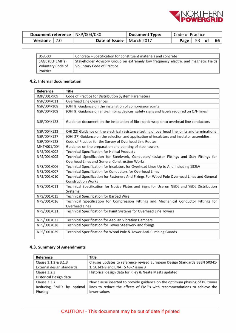
3.1. Tower Line Design Criteria ....................................................................................................................................... 7
3.1.1. Early tower designs .................................................................................................................................................. 7
3.1.2. Current Tower Line Designs ..................................................................................................................................... 7
3.1.3. Design theory to be applied to new or refurbished Tower Lines ............................................................................ 8
3.1.3.1. New Tower Lines .............................................................................................................................................. 8
3.1.3.2. Diversions, extensions, replacements or refurbishment of individual supports or tower lines ...................... 8
3.1.3.3. Upgrading existing lines to carry larger conductors ........................................................................................ 8
3.2. Design basis, Loadings and reliability requirements for tower lines ....................................................................... 9
3.2.1. General Approach .................................................................................................................................................... 9
3.3.1. Distribution system parameters ............................................................................................................................ 15
3.3.2. Line Ratings ............................................................................................................................................................ 15
3.4.3. Sag and tension Calculations ................................................................................................................................. 18
3.4.4. Engineering documents – associated with the manipulation of conductors ......................................................... 18
3.4.5. Conductor Material ................................................................................................................................................ 19
3.4.5.1. Standard Conductors Types on L4 (m) , (L7 (c) & L3 (c) Tower Lines ............................................................. 19
3.4.5.8. Line Terminations .......................................................................................................................................... 22
3.4.5.9. Final Inspection, test certificates and installation records ............................................................................ 22
3.6.1. Sag adjusters .......................................................................................................................................................... 28
3.8.9. Tower Erection or steelwork replacement ............................................................................................................ 38
3.8.10. Tower - Type and range ......................................................................................................................................... 39
3.8.11. Tower - Standard height supports ......................................................................................................................... 39
3.8.18. Safety Flag Sockets, Wristlets and Circuit ID’s ....................................................................................................... 41
3.8.19. Safety Signs and identification plates .................................................................................................................... 41
3.8.21. Foundation Design ................................................................................................................................................. 42
3.8.22. Foundation Materials............................................................................................................................................. 42
3.8.25. Construction and installation of foundations ........................................................................................................ 43
3.8.25.1. Foundation Installation method statement ................................................................................................... 43
3.8.25.2. Site working area ........................................................................................................................................... 43
3.8.26. Excavation support ................................................................................................................................................ 44
3.8.26.4. Placing and compacting ................................................................................................................................. 44
3.8.27. Foundation Joints ................................................................................................................................................... 44
3.8.27.1. Foundation Curing and protection ................................................................................................................. 44
3.8.27.2. Foundation Stub setting ................................................................................................................................. 44
3.8.27.3. Foundation Backfilling.................................................................................................................................... 44
3.8.29. Foundation Stub – concrete interface ................................................................................................................... 44
3.8.29.1. Foundations - Construction of Muffs ............................................................................................................. 45
3.9. Foundation Inspections on existing towers ........................................................................................................... 47
3.9.1. Non-Intrusive Foundation Inspections on existing towers .................................................................................... 48
3.11. Site Investigations .................................................................................................................................................. 48
3.11.1. General .................................................................................................................................................................. 48
3.11.1.1. Site investigation ............................................................................................................................................ 49
3.11.3. Desk Study ............................................................................................................................................................. 49
3.11.4. Applied foundation loading ................................................................................................................................... 49
Appendix 2 – Tower type Recognition Guide ................................................................................................................. 58
Document reference NSP/004/030 Document Type: Code of Practice
Version:- 2.0 Date of Issue:- March 2017 Page 7 of 66
CAUTION! - This document may be out of date if printed
3. Technical Specification
3.1. Tower Line Design Criteria
3.1.1. Early tower designs Early tower design specifications were often unique to particular tower contractors and utilised design methodologies based on the Empirical Approach or what is now more commonly referred to as deterministic based designs. This design approach applied fixed levels of wind and ice load to the overhead conductors and supports (irrespective of the location of the tower line). These loads were then compared against with stated ultimate capabilities of components used in the design with each component limited by a stated factor of safety. The earlier generation of towers were designed in accordance with the Electricity Commissioners Regulations (revised 1947). 66kV lines were generally designed to withstand 8lb per sq.ft. (380n/m²) of wind pressure acting on ice loaded conductors augmented by with 3/8” (19mm) of radial ice. 132kV tower lines were typically specified to carry an increased ice coating of ½” (12.5mm) radial ice. The later generation of these tower builds resulted in tower lines standardising on the PL16, PL1 & L3 - 275kV construction specifications using these same design loadings. All lines designed to these earlier standards were designed to provide a minimum factor of safety of 2.5 when subjected to the above weather loads applied at 22ºF (-5.6ºC) and for a maximum conductor operating temperature of 122ºF (50ºC). In the 1970-80’s a suite of ESI documents later renamed ENA TS documents were produced to reflect the current practice within the industry and to standardise the designs of towers. At this time all towers were designed to comply with the “Electricity (Overhead Line) Regulations 1970”
The prime documents being:
Specification Description
ENA TS 43-6 Construction of Overhead Transmission Lines on Steel Towers for 132kV and higher voltages
A selection of supporting documents was also created at this time to provide details on all the components used within the build of tower lines. The above designs were all based on 380n/m² wind acting on conductors when they were covered with 12.5mm radial ice with all supports designed to provide a minimum factor of safety of 2.5 when subjected to the above weather loads applied -5.6ºC and for a maximum conductor operating temperature 70ºC. The issue of the “Electricity Supply Industry Regulations 1988” withdrew the requirement for overhead lines to be designed to specific deterministic loading conditions and instead required distribution companies to design and build lines that were “fit for purpose”. In reality this had very little impact on the design of towers but it did open up the opportunity for new lines or uprated lines to be designed to the “General” or what is more commonly described as being the probabilistic approach.
3.1.2. Current Tower Line Designs In 2001 a new European harmonised standard BS EN 50341-1 covering the general design requirements of overhead electrical lines, which was initially published for lines with voltages exceeding 45kV but was later revised to cover all lines exceeding 1kV. This standard was designed as a common design specification for use by all countries within Europe. However in order to achieve adoption and agreement by all countries a complementary document BS EN 50341-3 was produced which contained
Document reference NSP/004/030 Document Type: Code of Practice
Version:- 2.0 Date of Issue:- March 2017 Page 8 of 66
CAUTION! - This document may be out of date if printed
(NNA’s) National Normative Aspects to reflect existing national laws or regulations relating to the design and/or construction of overhead lines, climatic conditions and current national practices relevant to each country. In the case of the UK this resulted in BS EN 50341-3-9. The UK NNA allows for the two design approaches for both the mechanical and electrical design, the “General approach” based on the application of probabilistic reliability theory and an “Empirical Approach” based on the long term European experience of fixed deterministic loads. In 2005 to assist in the application of these standards ENA TS 43-125 was produced. This document titled “design guide and technical specification for overhead lines above 45kV” supersedes the majority of the original ESI or ENA TS standards.
3.1.3. Design theory to be applied to new or refurbished Tower Lines
3.1.3.1. New Tower Lines New tower lines will be designed to be fully compliant with the General Approach design principles detailed in BS EN 50341-1 and BS EN 50341-3-9. Unless specifically varied within this document, this will be achieved through the use of all new tower supports being specified to be in accordance with ENA TS 43-7 Issue 3 – L4(M) or ENA TS 43-9 issue 2 – L7 (c). Additionally the line will be required to be constructed and erected in accordance with clauses within ENA TS 43-125 appropriate to the General Approach.
3.1.3.2. Diversions, extensions, replacements or refurbishment of individual supports or tower lines The design of supports and conductor loadings related to the refurbishment, reconductoring, tee-offs, extensions or diversions to existing lines will utilise the Empirical Approach using the original tower design specification details detailed in Clause 3.2.3 of this specification. Where replacement supports are required they shall be specified to ENA TS 43-7 Issue 3 – L4(M) or ENA TS 43-9 issue 2 – L7(c) unless specified otherwise within the project specification or this specification. Additionally the line will be required to be constructed and erected in accordance with clauses within ENA TS 43-125 appropriate to the Empirical Approach. Where existing lines are of a CEGB 275kV “L3” construction they shall be replaced with “L3 (c) supports with all other design aspects being to the original design standard.
3.1.3.3. Upgrading existing lines to carry larger conductors Where existing tower lines are being considered for the application of larger CSA conductors than those applied when the line was originally constructed, this may be achieved in two ways. Use of the Empirical approach and the Identification of unused design capacity within the existing tower line e.g. where a line has not been constructed to the original design max spans the additional unused capacity can be compared on a prorate basis against the slight increased windspan and weight span values created by the larger conductor with all original conductor loading cases remaining the same as those used in the original design specification. The line shall then be modelled using tower cad to confirm that all clearance requirements in NSP/004/011 can be satisfied. Where the above method results in design loads in excess of the original design specification or all ground clearance requirements cannot be complied with, then the line shall be subjected to a design study based around the “General Approach” detailed in BS EN 50341-1 and BS EN50341-3-9 which typically result in the allowance of higher conductor erection tensions, and therefore reduced sags but with an attention to detail of key components needing that need strengthening to allow the use of the higher tensions. The design study is tower and site specific.
Document reference NSP/004/030 Document Type: Code of Practice
Version:- 2.0 Date of Issue:- March 2017 Page 9 of 66
CAUTION! - This document may be out of date if printed
3.2. Design basis, Loadings and reliability requirements for tower lines
3.2.1. General Approach New tower lines designed in accordance with the General Approach shall unless specified differently in the project specification have the loadings applied to the line, the associated partial load factors and the corresponding reliability levels required to ensure that the overhead line successfully resists these loadings specified as detailed in ENA TS 43-125 clause 3.5.
3.2.2. Empirical Approach New tower lines designed in accordance with the General Approach shall unless specified differently in the project specification have the loadings applied to the line, the associated partial load factors and the corresponding reliability levels required to ensure that the overhead line successfully resists these loadings specified as detailed in ENA TS 43-125 clause 3.6.
Document reference NSP/004/030 Document Type: Code of Practice
Version:- 2.0 Date of Issue:- March 2017 Page 10 of 66
CAUTION! - This document may be out of date if printed
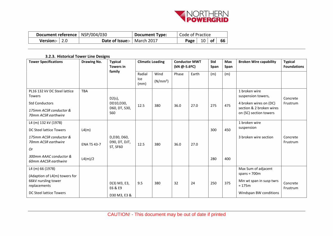
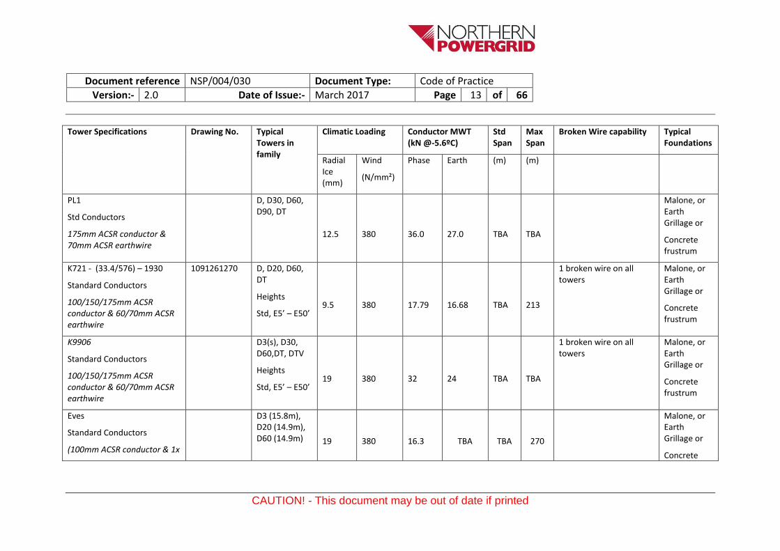
3.2.3. Historical Tower Line Designs Tower Specifications Drawing No. Typical
Towers in family
Climatic Loading Conductor MWT (kN @-5.6ºC)
Std Span
Max Span
Broken Wire capability Typical Foundations
Radial Ice (mm)
Wind
(N/mm²)
Phase Earth (m) (m)
PL16 132 kV DC Steel lattice Towers
Std Conductors
175mm ACSR conductor & 70mm ACSR earthwire
TBA
D2(s), DD10,D30, D60, DT, S30, S60
12.5
380
36.0
27.0
275
475
1 broken wire suspension towers,
4 broken wires on (DC) section & 2 broken wires on (SC) section towers
Concrete Frustrum
L4 (m) 132 kV (1978)
DC Steel lattice Towers
175mm ACSR conductor & 70mm ACSR earthwire
Or
300mm AAAC conductor & 60mm AACSR earthwire
L4(m)
ENA TS 43-7
L4(m)/2
D,D30, D60, D90, DT, DJT, ST, SF60
12.5
380
36.0
27.0
300
280
450
400
1 broken wire suspension
3 broken wire section
Concrete Frustrum
L4 (m) 66 (1978)
(Adaption of L4(m) towers for 66kV nursling tower replacements
DC Steel lattice Towers
D(3) M3, E3, E6 & E9
D30 M3, E3 &
9.5
380
32
24
250
375
Max Sum of adjacent spans = 700m
Min wt span in susp twrs = 175m
Windspan BW conditions
Concrete Frustrum
Document reference NSP/004/030 Document Type: Code of Practice
Version:- 2.0 Date of Issue:- March 2017 Page 11 of 66
CAUTION! - This document may be out of date if printed
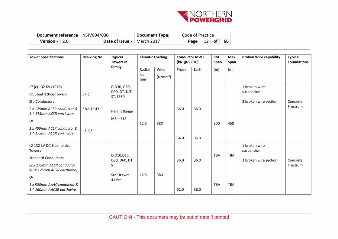
Tower Specifications Drawing No. Typical Towers in family
Climatic Loading Conductor MWT (kN @-5.6ºC)
Std Span
Max Span
Broken Wire capability Typical Foundations
Radial Ice (mm)
Wind
(N/mm²)
Phase Earth (m) (m)
Std Conductors
.15” ACSR conductor & .06” ACSR Earthwire
Or
175mm ACSR conductor & 70mm ACSR earthwire
E6
D60 M3 & M6
D90 (3way), & DTV
=170m
BW F of S = 1.5
Notes
Where this tower type is used as a replacement for an existing K9906 tower it shall be based on the L4(m) M.3 body giving a std height of 14.7m to the bottom crossarm. When used in association with EVE 0.1” ACSR towers they shall be based on the L4(m) M.6 body giving a std height of 11.7m to the bottom crossarm in the latter case a new butt splice will be required at the bottom of the main legs.
L3 or L3 (c) - (1956) 275 kV DC Steel lattice Towers
Standard Conductors
(2 x 175mm ACSR conductor & 1x 175mm ACSR earthwire)
Document reference NSP/004/030 Document Type: Code of Practice
Version:- 2.0 Date of Issue:- March 2017 Page 14 of 66
CAUTION! - This document may be out of date if printed
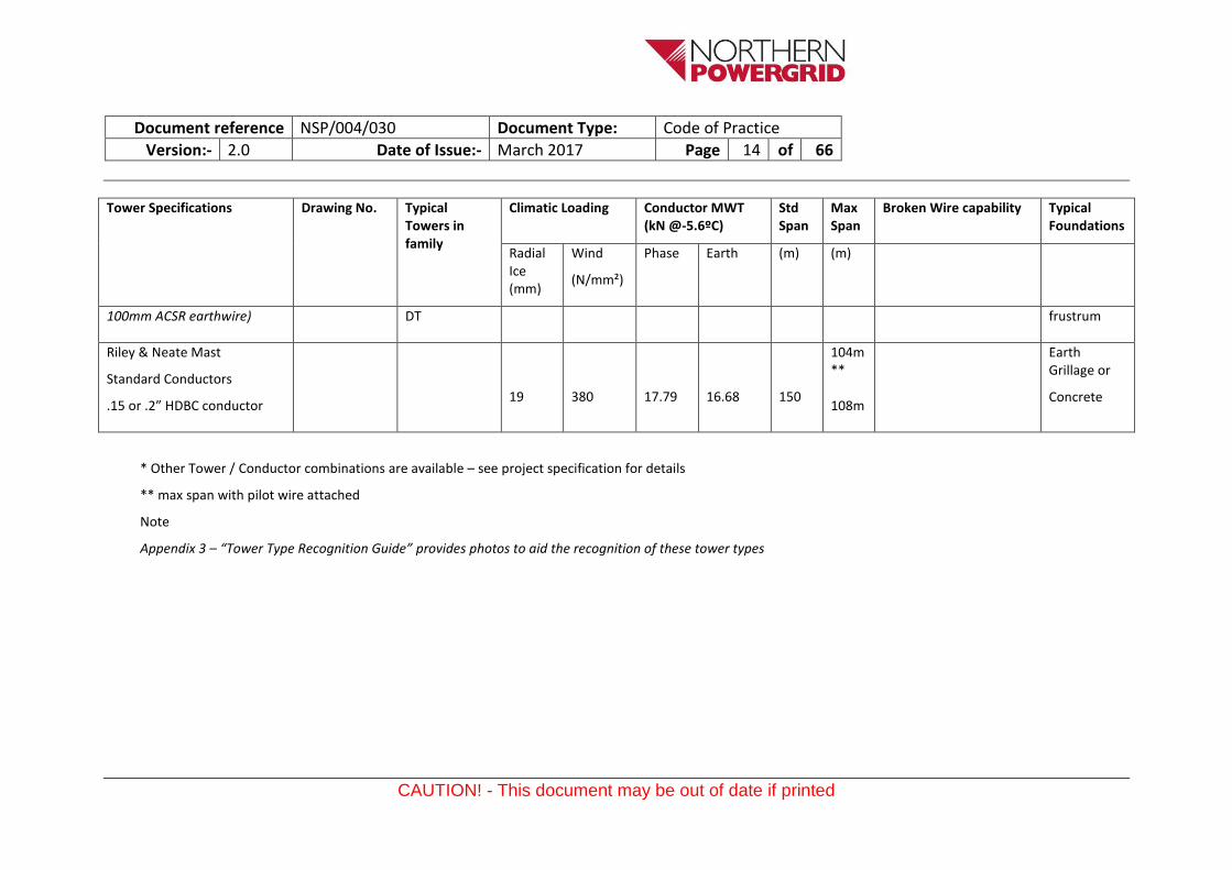
Tower Specifications Drawing No. Typical Towers in family
Climatic Loading Conductor MWT (kN @-5.6ºC)
Std Span
Max Span
Broken Wire capability Typical Foundations
Radial Ice (mm)
Wind
(N/mm²)
Phase Earth (m) (m)
100mm ACSR earthwire) DT frustrum
Riley & Neate Mast
Standard Conductors
.15 or .2” HDBC conductor
19
380
17.79
16.68
150
104m **
108m
Earth Grillage or
Concrete
* Other Tower / Conductor combinations are available – see project specification for details
** max span with pilot wire attached
Note
Appendix 3 – “Tower Type Recognition Guide” provides photos to aid the recognition of these tower types
Document reference NSP/004/030 Document Type: Code of Practice
Version:- 2.0 Date of Issue:- March 2017 Page 15 of 66
CAUTION! - This document may be out of date if printed
3.3. Electrical Requirements This section of the specification covers the determination of the electrical requirements of the tower line with respect to system voltage, frequency, current rating insulation coordination including lightning performance, internal and external clearances.
3.3.1. Distribution system parameters The electrical system parameters applicable to 33-132kV tower lines shall be as detailed in IMP/001/909.
3.3.2. Line Ratings Guidance on the selection of overhead line ratings to be applied to both existing and new overhead Tower lines on the Northern Powergrid Distribution system shall be as specified in IMP/001/011. All new lines will be designed to provide a conductor maximum design temperature of 75ºC. Where lines are being considered for refurbishment with or without a conductor change, then the line shall be subjected to a overhead line clearance survey to confirm that the minimum existing statutory clearances have been achieved and to identify any potential line uprating opportunities.
3.3.3. Insulation Co-ordination Overvoltage protection and the corresponding protective arc gaps on existing porcelain or glass Insulator assemblies shall be designed to comply with ENA TS 43-125 clause 4.4.4. However insulator assemblies associated with the use of replacement composite insulators shall be as specified in NSP/004/127 and NPS/001/006.
3.3.4. Electrical Clearances to avoid flashover Electrical clearances to avoid flashover on lines designed to the General Approach shall be to ENA TS 43-125 clause 4.4.6.1. Lines designed to the Empirical approach shall not be less than the values stated in table 5.3.5.3 of BS EN 50341-3-9.
3.3.5. Internal Electrical Clearances Internal electrical clearances and corresponding load cases to avoid flashover between phases and phases and earth on lines designed to the General Approach shall be to ENA TS 43-125 clause 4.4.7.1. Lines designed to the Empirical approach shall not be less than the values stated in clause 4.4.7.2 and table 4.6 of ENA TS 43-125.
3.3.6. External Electrical Clearances – Clearances to obstacles and the ground For both the General and the Empirical Approach, external in-span clearances to the ground or other obstacles shall be in accordance with NSP/004/011.
3.3.7. Optimum Phasing of Double Circuit Tower Lines to reduces the effects of EMF’s On Double Circuit lines each circuit produces a magnetic field. The direction of that field is determined partly by the order of the three “phases” or bundles of conductors that make up that circuit. The fields produced by the two separate circuits can either reinforce each other or partially cancel each other. “Optimum phasing” can be defined as the relative phasing (or order of the three phases) of the two circuits that, to the sides of the line, produces the greatest degree of cancellation between the magnetic fields produced by the two circuits, and hence the lowest resultant magnetic field. The phases are usually referred to by the colours red, blue and yellow. “Untransposed” phasing has the same order each side, “transposed” phasing the opposite order:
Document reference NSP/004/030 Document Type: Code of Practice
Version:- 2.0 Date of Issue:- March 2017 Page 16 of 66
CAUTION! - This document may be out of date if printed
For the normal situation where the currents flow in the same direction in both circuits, the optimum phasing – the phasing that produces the lowest resultant field to the sides of the line - is transposed.
If the currents consistently flow in opposite directions, the optimum phasing becomes untransposed. For some lines, the currents in the two circuits vary independently and one or the other can change direction, sometimes daily, e.g. as a result of changing demand for electricity, sometimes less often, e.g. as a result of changing use of different power stations or the construction of new power stations. In these situations, it is not possible to identify an optimum phasing, and the existing phasing should be retained. In general, optimum phasing will be assessed for the relative direction and size of load flows in the two circuits which represent normal operating conditions for that line and which is likely to be so for a period of years.
A power line is connected at its ends to a substation by “downleads” as shown in the picture.
The order of these downleads therefore determines the phasing of the line and thus the level of controllable EMF’s created by the line. In accordance with the SAGE Voluntary Code of Practice,
Document reference NSP/004/030 Document Type: Code of Practice
Version:- 2.0 Date of Issue:- March 2017 Page 17 of 66
CAUTION! - This document may be out of date if printed
Northern Powergrid will take every opportunity to achieve the optimum phasing where the work required to do so is reasonable. It will normally be reasonable for Northern Powergrid to achieve optimum phasing for high voltage power lines when it can be done by means of reconfiguring these downleads. This would apply to new power lines and to the conversion of existing power lines.
Sometimes, the land space available and the need to preserve electrical clearances between the downleads results in it not being possible to achieve optimum phasing on an existing power line just by reconfiguring the downleads. Achieving optimum phasing would then require a new structure such as a phase-transposition tower or gantry, as such this is deemed as being unreasonable solely to achieve the optimum phasing.
The phasing of a line also affects its electrical characteristics, and this can affect the overall stability of the part of the power network it is connected to. The requirements on network stability are specified in the National Electricity Transmission System Security and Quality of Supply Standard NETS SQSS 2009.
As such wherever practicable, all downleads shall be organised so that the configuration of phases on each side of the tower line result in the minimum EMF impact in practise this will typically result in the need for phase reversal ie. top to bottom Red, Yellow, Blue on one and Blue, Yellow, Red on the other side.
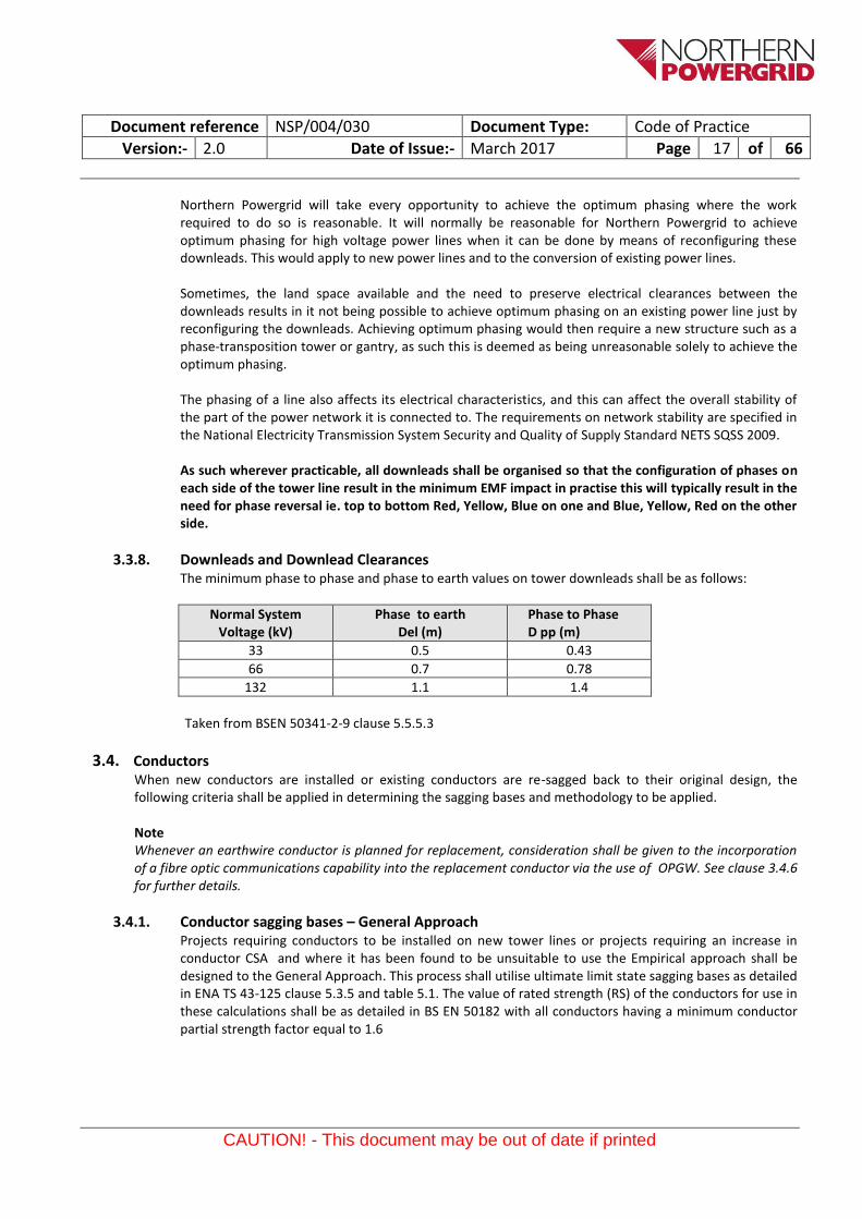
3.3.8. Downleads and Downlead Clearances The minimum phase to phase and phase to earth values on tower downleads shall be as follows:
Normal System Voltage (kV)
Phase to earth Del (m)
Phase to Phase D pp (m)
33 0.5 0.43
66 0.7 0.78
132 1.1 1.4
Taken from BSEN 50341-2-9 clause 5.5.5.3
3.4. Conductors When new conductors are installed or existing conductors are re-sagged back to their original design, the following criteria shall be applied in determining the sagging bases and methodology to be applied.
Note Whenever an earthwire conductor is planned for replacement, consideration shall be given to the incorporation of a fibre optic communications capability into the replacement conductor via the use of OPGW. See clause 3.4.6 for further details.
3.4.1. Conductor sagging bases – General Approach Projects requiring conductors to be installed on new tower lines or projects requiring an increase in conductor CSA and where it has been found to be unsuitable to use the Empirical approach shall be designed to the General Approach. This process shall utilise ultimate limit state sagging bases as detailed in ENA TS 43-125 clause 5.3.5 and table 5.1. The value of rated strength (RS) of the conductors for use in these calculations shall be as detailed in BS EN 50182 with all conductors having a minimum conductor partial strength factor equal to 1.6
Document reference NSP/004/030 Document Type: Code of Practice
Version:- 2.0 Date of Issue:- March 2017 Page 18 of 66
CAUTION! - This document may be out of date if printed
3.4.2. Conductor sagging bases – Empirical Approach Projects requiring existing conductors to be replaced or re-sagged back to design will normally be constructed and designed to the Empirical Approach utilising the “Ultimate limit state sagging bases” as detailed in ENA TS 43-125 clause 5.3.6 and table 5.2 The appropriate design levels of Radial Ice Thickness shall be appropriate to the original design ice thickness as detailed in the table of clause 3.2.3 of this specification. Additionally the Aeolian vibration limit shall be the Rated strength of the conductor (RS)/ 5.0 for aluminium based conductors or (RS)/3 for copper based conductors. The erection tension limit shall be such that when taking into consideration a 20ºC temperature correction for creep compensation the tension limit under combined wind and ice is not exceeded.
The rated strength of the conductors shall be as detailed in BS EN 50182 with a minimum conductor partial strength factor of 2.0
Over Tension Temperature shift for Creep compensation) (ºC)
Tension Limit (kN) * (ETL)
400 54 26 30 40
175 36 16 20 22
70 27 12 15 14
Design Wind Pressure 380N/m² Augmenting Constant 25mm (i.e. ice thickness x 2) * The assumed minimum conductor temperature when erecting short spans is 0ºC
3.4.3. Sag and tension Calculations The contractor shall submit the following design submissions to the company’s engineer:
Sag and tension calculations and schedules for the phase conductors and Earth wire for every span at the proposed range of sagging operations, the ultimate limit state loading conditions and at the maximum rated operating temperature of the phase conductor.
Proposed pre-tensioning regime with the associated allowances in conductor erection temperature to compensate for long term creep. It is typical on tower lines to apply a permanent overtension value equivalent to erecting the conductors at a lower ambient temperature that that experienced at the time of termination to compensate for long term creep. Typical temperature shift values can be found in the table in clause (see clause 3.4.2.1).
However it should be noted that the maximum conductor erection tension limit (ETL) as shown in the table in clause 3.4.2.1 must not be exceeded. The ETL limit state condition normally only applies on short spans. The contractor shall confirm this loading condition will not be exceeded.
3.4.4. Engineering documents – associated with the manipulation of conductors Appendix 2 provides a list of documents which shall be submitted to the engineer by the contractor at appropriate stages in the project directly associated with the erection or manipulation of overhead line conductors. These stages are typically designated as hold points and as such no work should progress beyond these points without the approval of the engineer.
Document reference NSP/004/030 Document Type: Code of Practice
Version:- 2.0 Date of Issue:- March 2017 Page 19 of 66
CAUTION! - This document may be out of date if printed
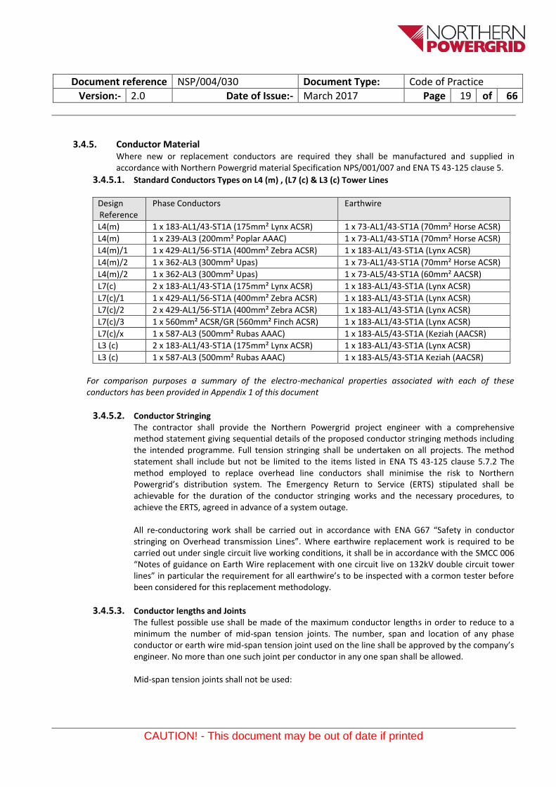
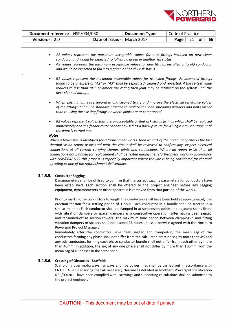
3.4.5. Conductor Material Where new or replacement conductors are required they shall be manufactured and supplied in accordance with Northern Powergrid material Specification NPS/001/007 and ENA TS 43-125 clause 5.
3.4.5.1. Standard Conductors Types on L4 (m) , (L7 (c) & L3 (c) Tower Lines
Design Reference
Phase Conductors Earthwire
L4(m) 1 x 183-AL1/43-ST1A (175mm² Lynx ACSR) 1 x 73-AL1/43-ST1A (70mm² Horse ACSR)
L4(m) 1 x 239-AL3 (200mm² Poplar AAAC) 1 x 73-AL1/43-ST1A (70mm² Horse ACSR)
L4(m)/1 1 x 429-AL1/56-ST1A (400mm² Zebra ACSR) 1 x 183-AL1/43-ST1A (Lynx ACSR)
L4(m)/2 1 x 362-AL3 (300mm² Upas) 1 x 73-AL1/43-ST1A (70mm² Horse ACSR)
L4(m)/2 1 x 362-AL3 (300mm² Upas) 1 x 73-AL5/43-ST1A (60mm² AACSR)
L7(c) 2 x 183-AL1/43-ST1A (175mm² Lynx ACSR) 1 x 183-AL1/43-ST1A (Lynx ACSR)
L7(c)/1 1 x 429-AL1/56-ST1A (400mm² Zebra ACSR) 1 x 183-AL1/43-ST1A (Lynx ACSR)
L7(c)/2 2 x 429-AL1/56-ST1A (400mm² Zebra ACSR) 1 x 183-AL1/43-ST1A (Lynx ACSR)
L7(c)/3 1 x 560mm² ACSR/GR (560mm² Finch ACSR) 1 x 183-AL1/43-ST1A (Lynx ACSR)
L7(c)/x 1 x 587-AL3 (500mm² Rubas AAAC) 1 x 183-AL5/43-ST1A (Keziah (AACSR)
L3 (c) 2 x 183-AL1/43-ST1A (175mm² Lynx ACSR) 1 x 183-AL1/43-ST1A (Lynx ACSR)
L3 (c) 1 x 587-AL3 (500mm² Rubas AAAC) 1 x 183-AL5/43-ST1A Keziah (AACSR)
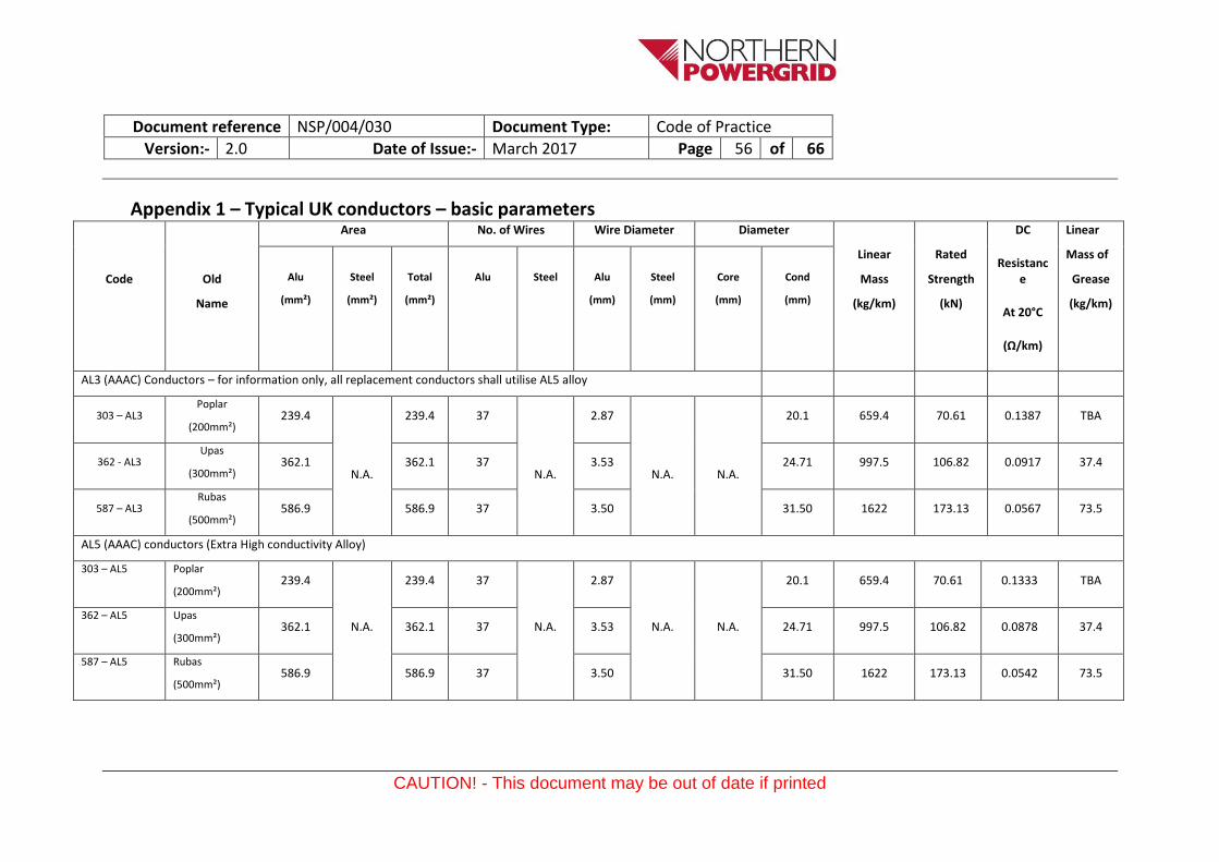
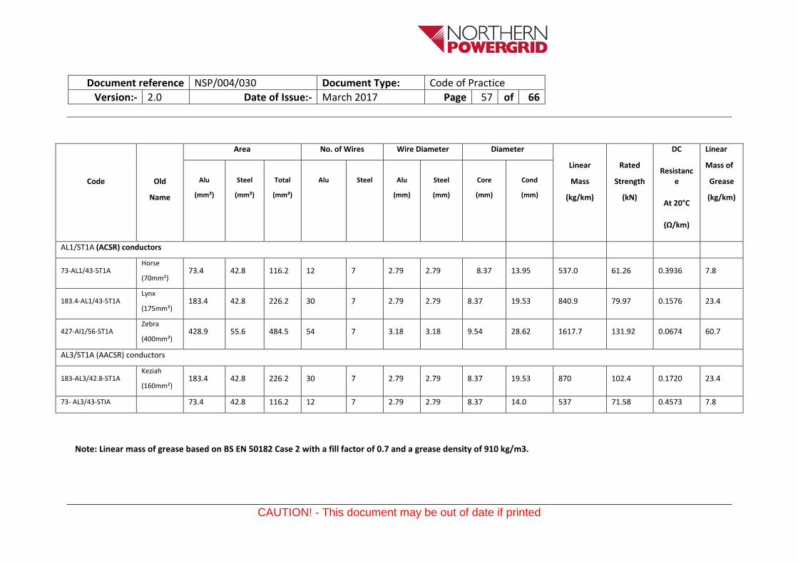
For comparison purposes a summary of the electro-mechanical properties associated with each of these conductors has been provided in Appendix 1 of this document
3.4.5.2. Conductor Stringing The contractor shall provide the Northern Powergrid project engineer with a comprehensive method statement giving sequential details of the proposed conductor stringing methods including the intended programme. Full tension stringing shall be undertaken on all projects. The method statement shall include but not be limited to the items listed in ENA TS 43-125 clause 5.7.2 The method employed to replace overhead line conductors shall minimise the risk to Northern Powergrid’s distribution system. The Emergency Return to Service (ERTS) stipulated shall be achievable for the duration of the conductor stringing works and the necessary procedures, to achieve the ERTS, agreed in advance of a system outage.
All re-conductoring work shall be carried out in accordance with ENA G67 “Safety in conductor stringing on Overhead transmission Lines”. Where earthwire replacement work is required to be carried out under single circuit live working conditions, it shall be in accordance with the SMCC 006 “Notes of guidance on Earth Wire replacement with one circuit live on 132kV double circuit tower lines” in particular the requirement for all earthwire’s to be inspected with a cormon tester before been considered for this replacement methodology.
3.4.5.3. Conductor lengths and Joints The fullest possible use shall be made of the maximum conductor lengths in order to reduce to a minimum the number of mid-span tension joints. The number, span and location of any phase conductor or earth wire mid-span tension joint used on the line shall be approved by the company’s engineer. No more than one such joint per conductor in any one span shall be allowed.
Mid-span tension joints shall not be used:
Document reference NSP/004/030 Document Type: Code of Practice
Version:- 2.0 Date of Issue:- March 2017 Page 20 of 66
CAUTION! - This document may be out of date if printed
a) Within 3 m of the conductor suspension clamp, line post insulator attachment or dead-end tension joint;
b) In sections between tension supports of less than three spans unless specifically approved; c) In spans over railways, navigable rivers, motorways, buildings or spans covered by special
wayleave conditions. A line shall be deemed to be over a building when, at the conductor maximum rated temperature with an assumed swing of 45° from the vertical, any part of the building is vertically below any conductor;
d) In any span immediately adjacent to a span as described in c), unless the support between such spans and adjacent spans is fitted with tension insulator sets.
e) In a span that over-sails a power line crossing
The contractor shall provide the engineer with a proposed conductor jointing schedule and details of resistance reading obtained for all joints for each section following completion of the conductor stringing works. The resistance values will be included for all joints in the final records issued to Northern Powergrid following completion of site works. Where joints are required they shall be installed in accordance with ENA TS 43-117 and Northern Powergrid guidance document NSP/004/108
3.4.5.4. Electrical resistance testing of joints and terminations The electrical resistance of all 66 & 132kV line and earth current carrying clamps, joints and electrical bonding connections shall be measured using digital micro ohmmeter (DMO) to establish an accurate measurement of these joints.
This work shall be carried out in accordance with ENA TS 43-117 and the Northern Powergrid guidance note – NSP/004/122. Upon completion of the testing a report shall be completed for each tower.
Description of fittings
Resistance category
Max Resistance In Microhms
70mm
ACSR
160mm
ACCSR
175mm
ACSR
200mm
AAAC
300mm
AAAC
400mm
ACSR
Status
Anchor Clamp
c/w bolted jumper terminal
Overall Measurement
P1 & P2
A2
A3
42
49
30
35
30
55
32
37
TBA
TBA
26
30
Green
R1 84 60 60 64 TBA 52 Amber
R2 N/a >90 >90 >90 TBA >80 Red
Full Tension
Mid span Joint
A2
A3
42
49
30
35
30
35
TBA
TBA
TBA
TBA
26
30
Green
R1 84 60 60 TBA TBA 52 Amber
R2 >120 >90 >90 TBA TBA 80 Red
Notes
Document reference NSP/004/030 Document Type: Code of Practice
Version:- 2.0 Date of Issue:- March 2017 Page 21 of 66
CAUTION! - This document may be out of date if printed
A2 values represent the maximum acceptable values for new fittings installed on new clean conductor and would be expected to fall into a green or healthy risk status.
A3 values represent the maximum acceptable values for new fittings installed onto old conductor and would be expected to fall into a green or healthy risk status
.
R1 values represent the maximum acceptable values for re-tested fittings. Re-inspected fittings found to be in excess of “A2” or “A3” shall be separated, cleaned and re-tested, if the re-test value reduces to less than “R1” or amber risk rating then joint may be retained on the system until the next planned outage.
When existing joints are separated and cleaned to try and improve the electrical resistance values of the fittings it shall be standard practice to replace the load spreading washers and bolts rather than re-using the existing fittings or where joints are re-compressed.
R2 values represent values that are unacceptable or Red risk status fittings which shall be replaced immediately and the feeder route cannot be used as a backup route for a single circuit outage until the work is carried out.
Notes When a tower line is identified for refurbishment works, then as part of the preliminary checks the last thermal vision report associated with the circuit shall be reviewed to confirm any suspect electrical connections at all current carrying clamps, joints and connections. Where no report exists then all connections not planned for replacement shall be tested during the refurbishment works in accordance with NSP/004/0122 this process is especially important where the line is being considered for thermal uprating as one of the refurbishment deliverables.
3.4.5.5. Conductor Sagging Dynamometers shall be utilised to confirm that the correct sagging parameters for conductors have been established. Each section shall be offered to the project engineer before any sagging equipment, dynamometers or other apparatus is removed from that portion of the works.
Prior to marking the conductors to length the conductors shall have been held at approximately the erection tension for a settling period of 1 hour. Each conductor in a bundle shall be treated in a similar manner. Each conductor shall be clamped in at suspension points and adjacent spans fitted with vibration dampers or spacer dampers as a consecutive operation, after having been sagged and tensioned-off at section towers. The maximum time period between clamping-in and fitting vibration dampers or spacers shall not exceed 36 hours unless otherwise agreed with the Northern Powergrid Project Manager. Immediately after the conductors have been sagged and clamped-in, the mean sag of the conductors forming any phase shall not differ from the calculated erection sag by more than 4% and any sub-conductors forming each phase conductor bundle shall not differ from each other by more than 40mm. In addition, the sag of any one phase shall not differ by more than 150mm from the mean sag of all phases in the same span.
3.4.5.6. Crossing of Obstacles - Scaffolds Scaffolding over motorways, railways and live power lines shall be carried out in accordance with ENA TS 43-119 ensuring that all necessary clearances detailed in Northern Powergrid specification NSP/004/011 have been complied with. Drawings and supporting calculations shall be submitted to the project engineer.
Document reference NSP/004/030 Document Type: Code of Practice
Version:- 2.0 Date of Issue:- March 2017 Page 22 of 66
CAUTION! - This document may be out of date if printed
Drawings confirming clearances and supporting calculations shall be submitted to the Northern Powergrid project engineer for approval. Where crossings involve major road crossings, the contractors shall confirm the traffic management arrangements necessary for the road crossing. Where Sky Cradles are proposed in place of scaffolding, attention shall be paid to the requirements of L43 “Safe use of Sky Cradles over public roads and railways” and L32/1 “Recommended procedure for erecting overhead lines over Motorways”
Where crossings are associated with Rail crossings, attention is drawn to the typical 20 week extended notification period. A Network Rail ‘Basic Asset Protection Agreement’ (BAPA) will need to be completed and signed by the Company Secretary and returned to the rail operator before a track possession date can be agreed. See also NSP/005/001 “Access Arrangements to Network Rail Infrastructure”
Alternative approved methods of protection can be utilised e.g. Catenery Stringing System
3.4.5.7. Downleads Downlead spans between terminal supports and substation anchor points shall be erected at reduced tensions in accordance with values stated in the original design specifications. Where no information is available they shall be set at a maximum design tension of 4.5kN. The insulators shall be of upright and inverted configuration and a swing clearance diagram shall be produced to confirm minimum phase to phase and phase to earth clearances have been attained. Where ground anchors are employed the down lead will be connected to the substation earth grid. The inverted insulator sets shall be positioned to ensure a minimum clearance of 2.4m is maintained between line and ground level.
3.4.5.8. Line Terminations Line termination fittings provide the connection interface between the downleads and the substation equipment and/or cable sealing ends. ENA TS 43-105 provides details on typical arrangements. See clause 3.6.8 for more details on the different types of fittings available. The proposed connections and arrangement will be submitted to the Engineer for comment in advance of material orders or installation. The proposed interface will need to be discussed in advance with the substation or underground cable contractors.
3.4.5.9. Final Inspection, test certificates and installation records Immediately prior to the handover of the overhead line, the contractor shall conduct a final line route inspection to ensure that the specified clearances are available to all towers, ground, obstacles etc. all temporary earths have been removed and that no extraneous objects are present.
At this time the contractor shall provide the Northern Powergrid project engineer with the following installation records.
a) Actual erection sags and tensions b) Actual sag adjustment settings and linkages c) Location of all conductor mid-span tension joints d) Location of all repair sleeves e) Electrical resistance values for tension and non-tension compression joints, repair sleeves,
compression type tee connectors, line termination fittings and compression spacers. f) List of any outstanding actions/ remedial works with a proposed date for completion of this
items.
Document reference NSP/004/030 Document Type: Code of Practice
Version:- 2.0 Date of Issue:- March 2017 Page 23 of 66
CAUTION! - This document may be out of date if printed
3.4.6. Optical Fibre Cable Installation This section of the specification covers the design, manufacture, installation and testing of the optical cable embedded in Optical Ground Wires (OPGWs). Where the project specification requires the installation of an optical fibre cable using the external fibre wrap methodology this shall be carried out in accordance with Northern Powergrid specification NSP/004/123 using optical fibre cable in accordance with clause 3.4.6.1
3.4.6.1. Optical Fibres Optical fibres shall be single mode fibre design manufactured and supplied in accordance with Northern Powergrid specification NPS/002/024.
3.4.6.2. Fittings and Accessories The OPGW and shall be used with approved conductor fittings that have been designed and tested in accordance with ENA TS 43-126.
3.4.6.3. Optical Joint Enclosures Optical joint enclosures shall be provided to protect the splice joints of optical fibres, either when individual lengths of fibre optic cable (OPGW) are jointed, or between the fibre optic cable and the underground fibre optic cable. The fibre optic joint enclosure shall protect the splice joint from both mechanical and environmental damage.
The optical joint enclosures shall be installed onto section supports immediately above the anti-climbing devices. The joint enclosure shall consist of an external steel or die cast aluminium housing and shall provide protection to BS 60529, IP 447, and an internal die cast aluminium or high impact plastic ABS box to BS EN 60529, IP 54.
The external housing shall be designed so that rain water is directed away from the door, and there shall be no water ingress when the door is opened. The top and bottom of the joint box shall be vented, and the vents provided with vermin shields. An M12 earthing boss complete with an M12 galvanised nut and lock washers shall be provided on the outside of the box.
The door of the box shall be fitted with captive hinges and shall be fastened shut by screw fixings. A hasp shall be provided on the door capable of taking a 10 mm padlock.
The bottom of the box shall be fitted with two gland plates, and each gland plate shall have two entry points. The gland plates shall be interchangeable, one style shall be used for fibre optic earthwire, the other for underground fibre optic cable. The joint boxes shall be supplied complete with all fittings to secure and seal the cable in the gland plates or blank the unused spigots. Cable cleats to secure the fibre optic cable (OPGW) or underground cable shall be fitted inside the box. The cleats shall not have a detrimental effect on the performance of the optical fibres when tightened to the recommended torque. The interior box shall be mounted on brackets inside the external housing and shall be capable of easy removal, complete with the optical fibre tails. The seal around the box shall be capable of withstanding a temperature range of -30°C to +60°C. The box shall be supplied complete with internal splice cassettes to accommodate the required number of splices. Glands shall be fitted to accommodate either the fibre optic cable (OPGW) or underground fibre optic cable.
Document reference NSP/004/030 Document Type: Code of Practice
Version:- 2.0 Date of Issue:- March 2017 Page 24 of 66
CAUTION! - This document may be out of date if printed
3.4.6.4. Fixing Cleats A bolted clamping system shall be used to attach the OPGW to the support, without drilling or modifications to the support steelwork. The clamping system shall be capable of use with galvanised steel angle sections varying between 40 mm and 200 mm wide, and accommodating either single, double or multiple lengths of OPGW.
The attachment clamps shall be capable of being attached and detached from the support, without affecting the OPGW.
3.4.6.5. Optical Fibre Tests All optical fibre cables shall be tested prior to despatch using an Optical Time Domain Reflectometer (OTDR) on each fibre, for attenuation, refractive index and dispersion at the specified wavelengths. Both prior to the installation of the fibre optic cable and after stringing of the cable, the cable shall be retested with and OTDR to confirm that : a) no damage has occurred to the fibre during delivery b) no damage has occurred to the fibre during installation In both cases the readings shall be compared with those results prior to despatch from the factory. In addition an end to end attenuation measurement shall be taken in each direction on each fibre using an optical source and optical power meter. An average of the measurements from both ends shall be deemed to quantify the system loss.
3.4.7. Conductor Testing Unless specified otherwise within the project specification, the requirement to test existing conductors shall normally be linked to a tower line being identified for refurbishment works or when asset records show that conductors are in excess of 45 years old and no previous conductor data is available. As such the conductor testing works shall be carried out ahead of the main refurbishment works to ensure the final scheme is scoped correctly. Conductor testing shall typically involve the application of the Cormon Overhead line Corrosion Detector (OHLCD) which is applied to ACSR conductors only and the retrieval of conductor samples for testing which applies to all conductor types.
3.4.7.1. Cormon Overhead Line Corrosion Detector Testing This is a remotely controlled device that when passed along the ACSR conductor, it will measure the integrity of the galvanizing layer on the steel core strands. Loss of galvanizing is a precursor to the onset of galvanic corrosion between the steel and aluminium cores of ACSR and provides an early warning of the potential need to replace the conductor. A single representative span of conductor with good tower access facilities shall be selected from the tower route. The optimum location is a span that might have achieved the maximum likelihood of corrosion from airborne pollutants eg at right angles to the coast line, at right angle to the prevailing wind direction or adjacent to any factories or processes that might create any form of pollution. Where a single line inspection site is likely to be unrepresentative of the line as a whole eg where a line runs at a low level and then rises to a multiple span section at a higher level or where the line is known to consist of different constructions then additionally test locations shall be chosen.
Document reference NSP/004/030 Document Type: Code of Practice
Version:- 2.0 Date of Issue:- March 2017 Page 25 of 66
CAUTION! - This document may be out of date if printed
Following completion of the site works a detailed analysis report with recommendations detailing the findings of the test and the condition of conductor and earth wire shall be submitted to Northern Powergrid, thereby enabling Northern Powergrid to identify any remedial works or a requirement to replace the conductors.
3.4.7.2. Conductor Samples The project specification will identify the number of conductor samples required for each overhead line route. A conductor sample will consist of consist of 3 separate lengths of a minimum of 5.0m of conductor taken from the following locations.
a) Taken adjacent to a conductor termination at a section tower (to include the termination fitting b) Taken at a mid-span point c) Taken across an insulator suspension set fitting (to include the vibration dampers).
Note Despite the need to obtain samples, the requirements of clause 5.7.3 of ENA TS 43-125 must still be observed. Adherence to the sampling methodology listed below will ensure no additional risk is created by this sampling requirement Note - Samples taken from jumper loops are not valid samples for the purposes of assessing the condition of the conductor.
The samples will be labelled:
1. Feeder name and circuit 2. Date 3. Location and tower number 4. sample type i.e. mid-span, suspension insulator position 5. Contact number and company
The samples will be packed with a protective material and transported to EA Technology Limited for examination and testing. The samples will determine if the conductor & earth wire can be retained.
Northern Powergrid will issue an order directly to EA Technology Limited for the conductor / earth wire analysis and test report.
Obtaining the samples and choosing the optimum location for the samples.
Select an intermediate suspension tower adjacent to a section tower where the conductor can be safely lowered to the ground in both spans at each side of the intermediate tower without the risk of damage to the conductor or adjacent property.
The conductor at the next intermediate tower shall be temporarily back stayed to maintain the tension in the remaining section of line.
The lowered 1.5 spans section of conductor shall be replaced with a new length of conductor by inserting a single mid-span tension joint and new conductor termination at the tension tower.
The three 5.0m samples shall then be obtained from this length of conductor at the points stated above.
Ideally the selected span will be representative of a span that is similar in length to the prevalent equivalent span of the tower line.
Document reference NSP/004/030 Document Type: Code of Practice
Version:- 2.0 Date of Issue:- March 2017 Page 26 of 66
CAUTION! - This document may be out of date if printed
The vibration dampers and suspension clamps shall be removed from the samples prior to coiling the conductors with clear marking applied to the conductor to indicate where they were previously applied. The vibration dampers will be the subject of separate investigations.
3.4.7.3. Testing conductor samples The conductor samples shall be subjected to the following tests:-
Dismantling the samples to provide a visual assessment of the condition of the strands
An assessment of the quality, quantity and condition of grease, making comparisons against ENA ER L38.
Identification of any evidence of corrosion or other significant deterioration
Torsion tests and tensile tests on individual strands
Calculation of the minimum breaking load for each of the conductor samples and comparison to the original conductor design standard.
Production of a condition report indicating the condition of the conductors together with a estimate of remnant service life.
Note - ACSR conductors installed prior to 1958 were known to be manufactured without the use of protective greases, hence particular attention shall be paid to any conductors falling into this vintage category.
Torsion Test For ACSR conductors the critical degradation process and dominant long term failure mode is corrosion. Corrosion particularly at the steel/aluminium interface results in progressive loss of ductility of the aluminium strands. Eventually these fail in a brittle manner and transfer the current to the steel, which overheats and fails. Once corrosion takes hold the lifetime of the conductor is relatively short. Corrosion can be accurately monitored by the ductility of the aluminium strands as measured by a simple torsion test. A new strand gives 25 – 30 twists to failure, once this value falls below 10 strand failures are likely.
Tensile Test Mechanical tests shall be carried out on the individual conductor strands using a tensile test machine. The load at 1% elongation and the maximum breaking load for six individual aluminium strands for both the outer and inner layers and two of the steel strands shall be measured and used to determine the tensile strength of the conductor. The breaking load of the conductor can be taken to be 95% of the sum of the strengths of the individual component wires calculated from the measured breaking load of the aluminium wires plus the sum of the breaking load of the individual steel wires calculated from the load at 1% elongation. These values shall be tabulated and compared against the BS 215 part 2 minimum breaking load values.
3.5. Insulators and insulator sets This section of the specification covers the design, manufacture, installation and testing of both individual insulator units and complete insulator string assemblies. For details of the associated insulator set fittings or conductor fittings see clause 3.6 of this specification. New or replacement insulator assemblies shall be manufactured from composite materials and supplied in accordance with Northern Powergrid material Specification NPS/001/006 and ENA TS 43-125 clause 5. For further guidance on the approved type of insulator or insulator assembly that should be utilised in specific overhead line situations see NSP/004/127 for details.
Document reference NSP/004/030 Document Type: Code of Practice
Version:- 2.0 Date of Issue:- March 2017 Page 27 of 66
CAUTION! - This document may be out of date if printed
Note The timing and shape of the Northern Powergrid investment plan relating to the rebuild or refurbishment of existing EHV overhead lines routes is impacted by the results of the CBRM and Health Models held for each component/support located in the overhead line route. The data used to populate these models is generally obtained from the scheduled overhead line inspection process as detailed in MNT/004 “Policy for the inspection and maintenance of Overhead Systems”. In the case of tower lines this is facilitated through the use of 10 yearly helicopter inspections using high resolution photography techniques.
As such the models provide a targeted plan detailing the timing and level of intervention required against each structure/component contained in each line.
However despite the use of this technology it is generally accepted that the design of suspension insulator strings can result in levels of deterioration which cannot be accurately quantified resulting in the risk of premature component failures. Hence whilst our company policy is to replace components on a condition basis rather than an age basis, we still recognise that certain components can sometimes mask their true condition from standard non-intrusive inspection procedures and thus require time based replacement.
Suspension Insulator assemblies are one such example where they shall be replaced on a time based frequency. As such all existing lines that incorporate suspension insulator string assemblies shall have all components that make up the assembly from the attachment point on the crossarm to the conductor clamp replaced once the fittings on the line exceed 45 years of age.
Where insulator strings assemblies are replaced on lines utilising existing overhead line conductors, care must be taken to reduce the risk of any premature failure of conductors at the point where they were previously held rigid. To reduce this risk all replacement insulator string assemblies shall include for the installation of new AGS (Armour Grip Suspension) units or suspension clamps and conductor line splice’s installed at the position of the previously held conductor.
Historical suspension insulator string assemblies where designed around 127mm disc centres, resulting in an overall string length of 1397mm. Whereas the latter generation of string assemblies were based around 140mm disc centres resulting in an overall string length of 1540mm. This difference in disc centres across the strings results in a typical increase in string length of 143mm. Thus care must be taken when selecting replacement string assemblies to ensure that this replacement process does not inadvertently create a ground clearance infringement.
As such insulator strings cannot be replaced without first ensuring that the feeder route has been subjected to a groundline survey. Where the historical string assembly did not employ the use of an insulator protective device as detailed in clause 3.6.9 then this can create further issues as modern string assemblies include arc protective devices at both ends of the string resulting in a further increase in the overall string length
Where this reduced clearance creates an issue with respect to the ground clearance requirements as detailed in clause 3.3.6 and NSP/004/011 then a replacement string assembly based around a 9 x 140mm disc equivalent rather than the standard 11 x 140mm disc equivalent assembly shall be used.
3.6. Insulator & Conductor Fittings This section of the specification covers the design, manufacture, installation of insulator and conductor fittings used to support or terminate the conductors or earthwire to the tower peak or crossarms. Insulator & Conductor Fittings shall be manufactured and supplied in accordance with Northern Powergrid specification NPS/001/005. Further reference shall also be made to clause 3.8.7 of this specification
Document reference NSP/004/030 Document Type: Code of Practice
Version:- 2.0 Date of Issue:- March 2017 Page 28 of 66
CAUTION! - This document may be out of date if printed
3.6.1. Sag adjusters All tension sets shall incorporate sag adjusters for adjusting the sag of either the individual phase conductors or sub conductors forming a phase bundle. The total range of linear adjustment and the individual increments shall be between 75-225mm using a standard sag adjuster plate to BS3288 ref 28/100 or with an additional 0-150mm where cranked links to BS3288, ref 28/87 are incorporated. The proposed arrangement shall be agreed between the contractor and the companies’ project engineer to best suit the conditions in each section of line. Where existing conductors are being retained the provision of sag adjusters will be dependent upon the ability to re-tension the conductors back to design conditions without the need to re-terminate the conductors.
If this cannot be achieved then they shall be omitted, however if conductors are re-terminated they must be installed.
3.6.2. Low duty tension insulator sets Unless stated to the contrary in the Project Specification, low-duty tension insulator sets shall incorporate a turnbuckle for adjusting the sag of the complete downlead. The turnbuckle where appropriate shall comply with the requirements of BS 4429, be fitted with locknuts and located at the earth end of the set.
3.6.3. Suspension clamps Suspension clamps must be manufactured from materials appropriate to the size and type of line conductors. Where suspension clamps are manufactured from malleable cast iron, and used on ACSR conductors, they must be specified to be supplied with aluminium liners to protect the soft aluminium conductor. Drawing 1091010498 sht1 and 2 provide typical details of clamps suitable for aluminium and copper based conductors. Where suspension insulator string insulator assemblies are replaced as part of refurbishment activities and the existing conductors are retained, then all suspension clamps must also be replaced. The replacement suspension string assemblies shall include for the installation of new AGS (Armour Grip Suspension) units or suspension clamps and conductor line splice’s installed at the position of the previously held conductor. Where line outage return to service considerations are particularly onerous on a route then with prior agreement consideration may also be given to the replacement of the suspension clamp and the use of conductor repair splices installed at the position of the previously held conductor.
3.6.4. Earthwire suspension clamps Earthwire suspension clamps shall fully meet the requirements of clause 3.6.3 of this specification and shall be provided with an earth bond attachment lug to facilitate the connection of earthwire bonds between the earthwire suspension clamps and the suspension tower peaks as detailed in clause 3.8.8 of this specification.
3.6.5. Anchor Clamps Anchor clamps and joints shall be manufactured and supplied in accordance with ENA TS 43-125 clauses 8.4.6 and Northern Powergrid specification NPS/001/016.
Document reference NSP/004/030 Document Type: Code of Practice
Version:- 2.0 Date of Issue:- March 2017 Page 29 of 66
CAUTION! - This document may be out of date if printed
Conductor terminations at section or terminal support towers shall utilise compression anchor clamps type fittings complete with jumper terminal flags for use with (two bolt) bolted jumper palms. See clause 3.6.7 for details on jumper lugs and load spreading washers.
Were AAAC conductors are being terminated then mechanical wedge type clamps may be used as an alternative termination type. See ENA TS 43-117 for assembly details.
The electrical resistance of all conductor joints, both tension and non-tension shall be measured by an approved digital micro ohmmeter in accordance with clause 3.4.5.4 of this specification and Northern Powergrid guidance document NSP/104/022. Where a temporary bypass jumper has been installed with PG (parallel groove) clamps this jumper will be removed and the jumper / anchor clamp replaced as necessary.
All resistance values shall be recorded and submitted to the Northern Powergrid project engineer.
3.6.6. Mid Span Tension Joints Mid span tension joints shall be of the compression type. See clause 3.4.5.4 for further details on those locations were Mid span joints are not allowed.
3.6.7. Jumper palms Palms for connecting jumper loops to dead ends, or tee connectors shall be compression type with either straight or 30º angle lugs. Jumper palms shall be supplied with bolt assemblies. Bolt assemblies shall consist of bolts and nuts to grade 8.8 / 8.0 in accordance with BS 4190 complete with load spreading washers. Load spreading washers shall be 44mm diameter and 9.5mm thick for M16 bolts. To prevent loosening in service the minimum installation torque shall not be less than 90Nm.
3.6.8. Line termination fittings Line terminations fittings shall be manufactured and supplied in accordance with Northern Powergrid specification NPS/001/016. See clause 3.4.5.8 for more details on line terminations.
Care shall be taken when compressing these fittings onto small jumper lengths where the remote end of the jumper is already terminated as the elongation of the compression can create bird caging of the aluminium conductors exposing the steel inner strands to the increased risk of corrosion.
3.6.8.1. Bi-metallic Bi-metallic line termination fittings shall be designed to prevent corrosion between dissimilar metals at this interface. Where this interface involves the use of copper terminals similar to those shown on drawing 1091010704 sht4 then these fittings shall be a bi-metallic compression pin terminal similar to those detailed on drawing 1091010704 sht 3.
3.6.8.2. Aluminium Where this interface involves the use of aluminium terminals, then a two bolt jumper palm with a hole spacing as detailed in ENA TS 41-16 fig 4 shall be supplied complete with bolts and load spreading washers as detailed in clause 3.6.7 Jumper lug to drawing 1.09.101.0102, sheet 9
3.6.9. Insulator protective fittings (Arcing Horns) Insulator strings are fitted with arcing horns to provide a level of insulation co-ordination to the tower line and any plant or equipment connected to it.
Document reference NSP/004/030 Document Type: Code of Practice
Version:- 2.0 Date of Issue:- March 2017 Page 30 of 66
CAUTION! - This document may be out of date if printed
New composite insulator string assemblies are now supplied complete with a fully compatible arcing horn assembly designed for either approach or non-approach situations. Further details on the approved insulator string assemblies and their associated arc gaps can be found in the Northern Powergrid Guidance document NSP/004/127. Where existing glass or porcelain insulator strings are replaced with similar units or existing string assemblies are modified then suitable Insulator protective devices used shall be selected from those detailed in Northern Powergrid material specification NPS/001/005 and BS3288 part 2. The arc gap applicable to the historical assemblies shall be as detailed in NPS/004/127. Where ground clearance investigations have identified ground clearance infringements, advice shall be sought from the company’s Overhead Line Engineer with a view to considering the use of non-standard insulator assemblies with reduced arc protective gaps or the removal of the earth end arcing horn to reduce the overall string length.
3.6.9.1. Requirements for lines fitted with Arcing horns that also incorporate surge diverters Where tower line circuits are fitted with surge arrestors at the remote ends of the line, the historical logic of installing reduced gaps on the arcing horns in the “Approach Zone” shall no longer be applied. Instead all arcing horn gaps shall be set as the “Non Approach Zone”.
3.6.10. Miscellaneous Fittings
3.6.10.1. Bird Flight Diverters Where bird flight diverters have been specified in the project specification to enhance the visibility of the conductors they shall be installed on both phase and earthwire conductors. The diverters shall comprise of a factory formed helical aluminium or copper rod with a central loop or a spring clip assembly with a stainless steel ring to allow the attachment of spherical marker in stabilised international orange colour. The marker shall be manufactured from a suitable material that is resistant to Ultra Violet radiation and designed as to not induce Aeolian vibration into the conductors. The number and location of the diverters shall be agreed between with the project engineer.
Further details on this marker device can be found on Northern Powergrid drawing 1091010036 sht5
3.7. Vibration dampers and spacers
3.7.1. Vibration dampers Vibration dampers shall be manufactured, supplied and erected in accordance with NPS/001/022 and with ENA TS 43-125 clause 9. The specific requirements for Aeolian vibration dampers will depend on the following factors: the geographic orientation of the line with respect to large bodies of water, the frequency of laminar winds (0.5 m/s to 10 m/s), the ground terrain, the nature of the ground cover and the everyday conductor tension (EDT) employed in the design. Vibration dampers shall be installed with sufficient approved conductor grease to ensure that the interface between the clamp and the conductor is filled with grease to exclude moisture. Any excess grease shall be removed after vibration damper installation. All clamps shall be set to the recommended torque figure which is stamped on the body of the fitting.
Document reference NSP/004/030 Document Type: Code of Practice
Version:- 2.0 Date of Issue:- March 2017 Page 31 of 66
CAUTION! - This document may be out of date if printed
Vibration dampers shall be installed at each end of all overhead line conductor spans, with one damper installed per conductor at each end of the span.
The position of the vibration dampers shall unless specified otherwise in the project specification be installed at a specified distance from the centre of the suspension clamp or the mouth of the dead end to the centre of the vibration damper clamps. Drawing 1091010180 sht1 provides details on typical vibration dampers together with installation spacing’s.
Earthwires, single conductor phases and bundles without spacers coupling the sub-conductors in the spans between 370m and 550m in length shall have two vibration dampers installed at each end of the span. Additionally bundle conductors with spacers in spans between 420m and 550m in length shall have two vibration dampers installed at each end of the span.
For all spans greater than 550m in length or sections of line with conductors erected with EDT’s in excess of 20% of the conductors rated, further guidance shall be sought from the company’s Overhead Line Engineer.
Where existing tower lines are refurbished by changing the existing insulator string assemblies whilst retaining the existing line and earth conductors,, then all vibration dampers must be replaced at this time.
3.7.2. Spacers and dampers Spacer dampers shall be installed on all twin bundled conductor tower lines. The spacer dampers shall be manufactured an installed in accordance with ENA TS 43-125 clause 10. Where there is a mid-span joint or repair sleeve on a conductor, the adjacent spacer damper must not be closer than 2m or further away than 12m from the mid-span joint or repair sleeve. If possible, this configuration should be achieved using the correct configuration of spacer damper positions as indicated by the suppliers installation guide. Spacer dampers shall be installed with sufficient approved conductor grease to ensure that the interface between the clamps and the conductors are filled with grease to exclude moisture. Any excess grease shall be removed after spacer damper installation. All clamps shall be set to the recommended torque figure which is stamped on the body of the fitting.
3.8. Tower Design Towers shall be designed to resist the specified loads detailed in clause 3.1 of this specification taking into consideration the desired level of reliability, and the corresponding partial load and strength factors associated with each material component. All towers having being designed to facilitate inspection, painting, maintenance, repairs, operation and associated Health & Safety requirements with the continuity of supply being the prime consideration. Lattice steel towers shall be designed in accordance with ENA TS 43-125 clause 11.4.9 Unless stated to the contrary in the project specification, the partial strength factors for tower steelwork shall be in accordance with table 4.2.11 (b) of BS EN 50341-3-9.
Document reference NSP/004/030 Document Type: Code of Practice
Version:- 2.0 Date of Issue:- March 2017 Page 32 of 66
CAUTION! - This document may be out of date if printed
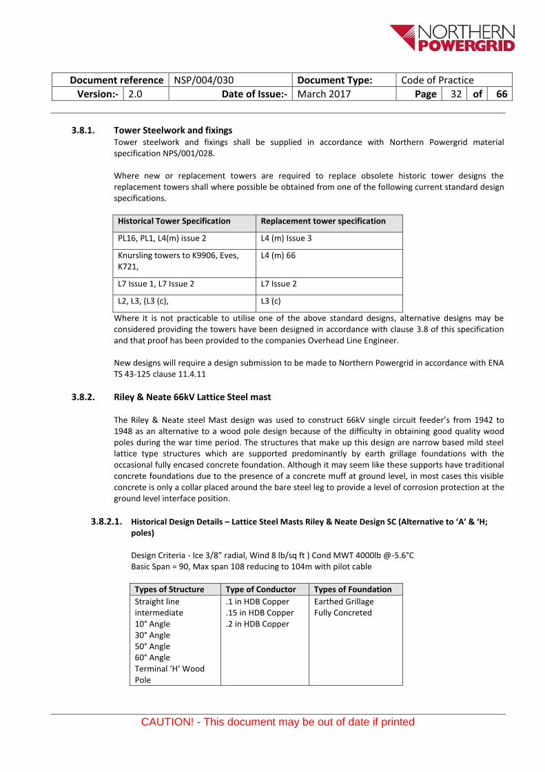
3.8.1. Tower Steelwork and fixings Tower steelwork and fixings shall be supplied in accordance with Northern Powergrid material specification NPS/001/028. Where new or replacement towers are required to replace obsolete historic tower designs the replacement towers shall where possible be obtained from one of the following current standard design specifications.
Where it is not practicable to utilise one of the above standard designs, alternative designs may be considered providing the towers have been designed in accordance with clause 3.8 of this specification and that proof has been provided to the companies Overhead Line Engineer. New designs will require a design submission to be made to Northern Powergrid in accordance with ENA TS 43-125 clause 11.4.11
3.8.2. Riley & Neate 66kV Lattice Steel mast
The Riley & Neate steel Mast design was used to construct 66kV single circuit feeder’s from 1942 to 1948 as an alternative to a wood pole design because of the difficulty in obtaining good quality wood poles during the war time period. The structures that make up this design are narrow based mild steel lattice type structures which are supported predominantly by earth grillage foundations with the occasional fully encased concrete foundation. Although it may seem like these supports have traditional concrete foundations due to the presence of a concrete muff at ground level, in most cases this visible concrete is only a collar placed around the bare steel leg to provide a level of corrosion protection at the ground level interface position.
The refurbishment of Riley & Neate Masts shall include the following works, unless otherwise specified:
The re-tensioning of all conductors (including earthwire where fitted)
The replacements of all fittings and insulators (replacing any mechanical joints with compression joints)
All 60 and 72° Section angle H masts shall be replaced with a wood pole equivalent structure
10 Degree suspension angle masts with ‘Milliken hangers’ should be converted to a tension insulator arrangement with the installation of a new section plate to drawing 66.5/10.1203 sht 2 and a knee bracket to drawing 66.5/10.1200 sht 4.
The refurbishment of all other masts including*:
The application of a protective paint system, including all cable support steelwork and concrete muffs
The replacement or repair of defective muffs
The clearance of all vegetation at the base of masts
Installation of barbed wire spacers on existing ACGs
Installation of enhanced ACGs on all supports deemed as high risk according to NSP/004/012 (normally achieved via a second level of ACGs above the existing).
Document reference NSP/004/030 Document Type: Code of Practice
Version:- 2.0 Date of Issue:- March 2017 Page 34 of 66
CAUTION! - This document may be out of date if printed
The identification and removal of any clearance infringements and where possible the thermal uprating of the route to its maximum permissible design temperature. (Where replacement supports will be required to achieve an uprating of the route, then the potential need shall be discussed with system design before any replacement supports are considered).
On an as needs basis
I. the replacement of any defective steel members II. the replacement of flat cross arm rakers for angle bar equivalents
III. the replacement of all step bolts (new step bolts installed on all masts in 2002).
• Any other defects identified during or prior to the proposed works shall be addressed,
Note Where the masts support a catenary wire, the following assessment shall be undertaken:- Is the catenary wire supporting a pilot and telephone cable? If so is the pilot still in working order?
I. For lines with a non-operational pilot wire supported by a catenary wire both wires should be removed.
II. For lines with an operational pilot cable supported by a catenary wire or where a non-operational pilot wire exists but where the route is deemed to be of operational importance, then consideration shall be given to the replacement of the pilot wire with a modern self-supporting fibre optic cable system eg an ADSS (All Dielectric Self Supporting) system.
Note: Fibre optic systems must be installed on an end to end basis (this can mean sections of fibre cable mid route or at the ends of the route) but this technology is not suitable for the replacement of small sections of catenary pilot wire, instead they would require a short section of traditional underground installed copper pilot/telephone cable to be installed.
i. For lines with a catenary wire only, the wire shall be removed, taking care to resolve any out-
of-balance tension situations created as a result. The catenary can only be removed on a section structure to section structure basis.
On some designs the catenary wire also operated as an aerial earthwire bonding all supports to earth at the remote ends of the circuit as opposed to each support being individually earthed. Where this is thought to be the case and the catenary earth has been or needs to be removed then earth continuity of the route shall be re-instated at the missing section by ensuring that the catenary wire is effectively bonded to the tower and then by earthing the tower at its base via the installation of a length of 70mm PVC Insulated earthing cable connected between the tower leg and an earth stake. The connection shall be achieved using a copper compression lug and a 12mm bolt in accordance with drawing 1.09.101.0146, Sheet 2. When a earth resistance test is carried out to confirm the effectiveness of the earth connection a maximum resistance value of 10 Ohms shall be achieved.
* On an as needs basis, individual supports may be considered for in-situ replacement with an equivalent wood pole design, where considered more economic (typically where the cost of the in-situ refurbishment >75% of the cost of replacing the support with a wood pole equivalent).
Assumptions Foundations are fit for purpose from both a design and condition perspective:
Document reference NSP/004/030 Document Type: Code of Practice
Version:- 2.0 Date of Issue:- March 2017 Page 35 of 66
CAUTION! - This document may be out of date if printed
Non-intrusive assessments shall be undertaken on all masts to assess the integrity of (or presence of) concrete and the likely levels of corrosion in the tower legs below ground
Intrusive foundation assessments on a representative sample of masts (10%) should be undertaken in advance of the construction phase
Existing overhead surveys (as provided) are fit for purpose, unless otherwise specified
3.8.3. Pre- construction Steelwork Inspection – Condition Assessment on existing towers In most refurbishment schemes a “pre-condition assessment” may have already been carried out on the tower line feeder using high resolution aerial photography or ground level patrol inspections using a condition rating (CR) system related to remaining asset life and based on a scoring mechanism of 1-5.
The photograph’s obtained from the above inspections methods are analysed with the results being tabulated into an excel spreadsheet for the tower line as a whole allowing a summary report to be created detailing the condition of the steelwork and components making up the tower line. Whilst the actual meaning of each CR value may vary dependent upon the component being described, the general outcome can be described as listed below.
In the context of tower steelwork condition the above ratings shall be taken as an initial guide as to the condition of the tower.
All towers must be re-assessed and or confirmed on site while undergoing refurbishment works against the more detailed scoring system specific to the condition of tower steelwork.
The following categories have been formed to create a grading system to identify the condition of tower steelwork on site and should be used as a guideline to replace or to maintain/paint the members. A report shall be returned to the company’s project engineer for each tower in the route.
Members graded 5 to 8 must be replaced with an equivalent metric section supplied in accordance with clause 3.8.1 of this specification.
1. Good condition / Paint-work - (This is equivalent to CR 1). 2. Light surface rust & local rust patches - (This is equivalent to CR 2) 3. Heavy surface rust - (This is equivalent to CR 2). 4. Local Pitting - (This is equivalent to CR 3). 5. Widespread Pitting - (This is equivalent to CR 4). 6. Delaminating - (This is equivalent to CR 4). 7. Extreme Corrosion & thin sections at some points - (This is equivalent to CR 4). 8. Extreme Corrosion & near failure - (This is equivalent to CR 5).
Condition Rating
Description
1 OK
2 Minor damage or corrosion with deterioration level <20%. Still fit for purpose for a minimum of 10 years
3 Damaged or corrosion with deterioration level >20% but <30%. Fit for purpose for >1 year but less than 10 years
4 Severe damage or corrosion with deterioration level >30%. No longer fit for purpose and shall be replaced.
5 Extreme damage or corrosion with deterioration level >50%. No longer fit for purpose and shall be replaced ASAP
Document reference NSP/004/030 Document Type: Code of Practice
Version:- 2.0 Date of Issue:- March 2017 Page 36 of 66
CAUTION! - This document may be out of date if printed
Where the use of the site inspection grading system indicates that the steelwork should be replaced rather than painted, the contractors shall provide photographic evidence to the engineer to substantiate their recommendations.
3.8.4. Tower Steelwork - Assessment System Grading Definitions
1 Good condition / Paint-work
No sign of rust, pitting or lamination on the entire surface of the section or plate with visible galvanising or protective paintwork
2 Light surface rust & local rust patches
Same as grade 6 above but thinner and not widespread.
3 Heavy surface rust
The rusting of steel is the most familiar example of corrosion, a complex chemical reaction in which the iron combines with both oxygen and water to form hydrated iron oxide. The oxide is a solid that retains the same general form, as the metal from which it is formed but, porous and somewhat bulkier, is relatively weak and brittle. The surface rust can easily be cleaned with wire brush and there should not be any damaged to the steel section or plate.
4 Local Pitting
Like grade 4 above, but not more than a single location and smaller than 16mm in diameter.
5 Widespread Pitting
Pitting occurs when corrosion is concentrated in local areas like holes. It is very harmful if pitting appears along the entire surface of the steel sections or plates.
6 Delaminating
Local or widespread lamination or flaking of steel sections or plates caused by corrosion.
7 Extreme Corrosion & thin sections at some points
Corrosion cells are readily formed between different areas on the steel surface owing to local variations in the steel or oxygen content of the water in contact with the steel. Consequently, the section has become thin in places.
8 Extreme Corrosion & near failure
This is heavy rusting of steel where corrosion cells are formed along the entire areas on the steel surface. Deposition of rust has not prevented further corrosion and the corrosion rate is increased because of its tendency to hold moisture. Consequently, the steel section has become near failure.
Document reference NSP/004/030 Document Type: Code of Practice
Version:- 2.0 Date of Issue:- March 2017 Page 37 of 66
CAUTION! - This document may be out of date if printed
3.8.5. Tower Steelwork – Fabrication drawings Fabrication drawings for steel members
Contractors will be responsible for obtaining copies of the appropriate fabrication drawings for any replacement members for the PL16, L7 and L4 (M) towers. Complete libraries of these drawings are currently managed on behalf of the DNO’s (Distribution network Operators) by PB Power.
3.8.6. Steel Towers – Step Bolts All towers legs shall be provided with the provision for step bolts of an approved type located at not more than 380mm centres starting immediately above the anti-climbing device and continuing to the earthwire peak. Each step bolt shall be fitted with one washer under the fixing nut with the first step bolt below each crossarm or gantry located on the traverse face of the tower and the remaining step bolts fitted alternatively on the remainder of the tower body and on the extensions. Below the anti-climbing devices the step bolt holes shall be provided at no more than 380mm centres on the legs used for climbing. Where the pre-construction steelwork inspection criteria in clause 3.8.3 has categorised the existing tower step bolts with CR ratings of 3 or 4 then the step bolts shall be replaced using replaced bolts as specified in Northern Powergrid material specification NPS/001/028.
3.8.7. Steel towers - Conductor and earthwire attachments Suspension insulator sets and earthwire attachments shall be attached to the tower crossarms or tower peaks using shackles or shackles and links as shown on drawing ENA TS 43-7 fig 6 or ENA TS 43-9 fig 6
A number of historical lines designs utilise U bolt arrangements to create the interface between the tower crossarm /earthwire peak and the suspension insulator sets and earthwire attachments. Northern Powergrid drawing 1091010501 sheets 1-3 provides details on those fittings required for PL16 towers.
Due to the limited availability of these items and their propensity to wear Northern Powergrid, typically carries stock of these items against stock cat numbers 252950, 252951 & 252952 respectively. An approved alternative is to replace the ‘U’ bolt with an angle bracket secured via two bolts (see OHL fitting sketch).
Additionally on some older tower line designs, typically PL16 and PL1 the suspension insulator sets may have “Milliken hangers” interposed between the tower crossarms and the shackles. Where these tower line designs are refurbished and insulators sets are replaced, it shall be standard practise to remove the hangers and to modify the tower crossarm assembly to accommodate direct attachment of the suspension insulator shackles thus typically increasing ground clearances by 300mm. Note this action will normally require an additional shackle to be inserted to re-orientate the suspension set arcing horns to align with the conductors.
Tension insulator sets and earthwire(s) attachments shall be attached to tower crossarms or tower peaks using shackles or swivels as shown typically on drawing ENA TS 43-7 fig 7 or ENA TS 43-9 fig 7 Where insulator string assemblies or earthwire attachments are replaced on tower lines it shall be standard practise to replace the above shackles/swivels, U bolts or shackles and link assemblies as they typically suffer from severe wear.
Document reference NSP/004/030 Document Type: Code of Practice
Version:- 2.0 Date of Issue:- March 2017 Page 38 of 66
CAUTION! - This document may be out of date if printed
3.8.8. Earthwire bonds The earthwire shall be bonded to all towers using flexible earthwire bonds manufactured and supplied as detailed in ENA TS 43-109. On suspension towers this will be achieved through the use of flexible bonds connected between the tower steelwork and suspension clamps generally in accordance with BS3288-2 fig 77 which are provided with dedicated earth lugs. The length of the bond wire shall be sufficient to ensure free movement of the suspension clamp. At section and angle towers a through jumper of the same material as the existing earthwire shall be used to form a connection between each earthwire tension clamp. In addition each earthwire tension clamp shall be separately bonded to the tower steelwork using a flexible earth bond. At terminal towers a jumper of the same material as the existing earthwire shall be connected to an aluminium plate as detailed on drawing ENA TS 430608 and bolted to the tower steelwork
.
3.8.9. Tower Erection or steelwork replacement The contractor shall provide the engineer with a comprehensive method statement giving sequential details of the proposed erection methods including his intended programme. The erection shall be carried out in accordance with guidance given in the relevant parts of BS 5531, BS DD ENV 1090-1 and current health and safety legislation. It should be noted as a general requirement that no support erection can commence before approval of the method statement by the engineer has been obtained. The Contractor shall ensure that supports are not strained or damaged in any way during erection. As far as practical bolt heads, rather than nuts shall be on the inner or downward faces of support joints. Members that will not fit together without undue force during erection of the support steelwork shall be aligned by slackening all bolts local to the non-fitting member, to enable assembly to proceed. All bolts shall then be re-tightened. All holes that align through both components of double angles (back to back) members shall be filled by fitting a bolt, with suitable pack washers or plates between the components. All spare holes (e.g. holes for alternative positions of supplementary fittings) in double angle members shall be included in this requirement. Each panel shall be checked and verified for squareness and level, as indicated on the erection drawings before the Contractor is allowed to proceed with erecting any further panels. Particular attention shall be given to erected panels containing bent leg members. If the panel is found not to be square or level, all bolts within the panel shall be loosened and the squareness and level corrected. All bolts shall be subsequently retightened. Approved locking devices, locknuts etc., shall be fitted after the full support has been erected and the bolts checked for tightness. Locknuts shall only be applied at the phase conductor and earthwire attachment points or other likely vibration points on the support. Supports shall be erected vertically within a tolerance of 0.5 % of the overall support height before conductor erection, unless specified otherwise on the erection drawings.
Document reference NSP/004/030 Document Type: Code of Practice
Version:- 2.0 Date of Issue:- March 2017 Page 39 of 66
CAUTION! - This document may be out of date if printed
The contractor shall provide the company’s project engineer with a comprehensive method statement giving sequential details of proposed erection methods. These shall include but not be limited to:
a) Maintaining safe working clearances during member replacement b) Methods for dealing with the compressive or tension capabilities of a support member whilst it is
being replaced to maintain the towers integrity. c) Panel assembly (fabrication drawings) d) Erection drawings if not included in the above e) Proposed field material lists in an (excel file format) f) Foundation setting diagrams g) Stub and cleat, holding down bolt assemblies
Panel assembly drawings shall show all materials in place, complete with all fabrication and connection details. A complete tabulation listing all pieces required for that portion of the support detailed shall be shown on each drawing. Each erection diagram shall show one support panel, together with a key diagram indicating its location on the complete support. For steel and timber poles only one erection diagram for the complete support shall be provided, unless otherwise agreed. Each piece shall be identified by its erection mark number. The number and length of bolts and number and type of nuts and washers required for proper assembly shall be shown at each connection. A complete tabulation listing all the material needed for the support panel or section including all bolts, nuts fill and bevel washers and locknuts, shall be shown on each drawing. The tabulation shall show the quantity, the mark number, the description of the piece (including size and length), the total mass (including an allowance of 3.5 % additional mass for galvanizing) to the nearest 0.1 kg of all the pieces of the same erection mark, and the number of the drawing on which the shop detail can be found. The quantities shall include 5 % excess of step bolts, bolts, nuts, fill and bevel washers and locknuts shall be shown. Field material lists shall provide similar tabulation details to those described above for erection diagrams. All erection diagrams shall show the allowable safe working loads adjacent to all construction and maintenance attachment points.
3.8.10. Tower - Type and range The type and range of towers shall include but not be limited to intermediate or (suspension) towers often referred to as D (s) or D2 (s), small deviation section towers D10º or D20º or D30º, large deviation section towers D60º and or D90º together with Junction Towers DJT and Terminal towers DT with a range of extensions and reductions.
Lattice steel towers shall be self-supporting towers designed to accommodate an out of balance tension across the tower together with various combinations of extreme out of balance created by broken wire conditions.
3.8.11. Tower - Standard height supports Standard height lattice steel towers shall be designed to support the lowest phase conductors at the defined external clearances stated in clause 3.3.6 above the ground with the conductors operating at their stated maximum rated temperature assuming such supports are at the same level on level ground and at the standard span length apart.
Document reference NSP/004/030 Document Type: Code of Practice
Version:- 2.0 Date of Issue:- March 2017 Page 40 of 66
CAUTION! - This document may be out of date if printed
3.8.12. Tower – Extensions Each type of tower has been designed to allow variations in height with respect to the standard height support. The extension may be either an increase, or decrease in height with respect to the standard height tower. Typically towers are increased or decreased in 3m or 10’ increments. Reference to the design specification for the particular family of towers is required to confirm the range and type of extensions.
3.8.13. Tower - Angle supports Unless stated to the contrary in the design specification, all angle towers at the minimum angle of deviation, shall have the mean horizontal separation between circuits not less than that of the suspension or intermediate tower. Small angle sections towers may be used in straight line positions where it is necessary to arrange for sectioning and tensioning of the conductors.
3.8.14. Tower - Terminal supports Terminal towers shall provide the corresponding circuit separation at the angle of entry stated in the design specification, with additional phase conductor attachment points provided to accommodate alternative angles of entry. Terminal/Junction towers will normally be erected with the plane of crossarm parallel to the line landing structures. Where cable support platforms are required these shall be supplied with decking and stone guards as standard unless the specification specifically states these are not required.
3.8.15. Tower - Earthing systems All towers foundations shall be effectively connected with earth with a minimum target footing resistance of less than 10 Ohms. All earthing systems shall be in accordance with ENA TS 43-125 clause 4.5 and ENA TS 41-20.
3.8.16. Tower Painting All towers shall be painted in painted in accordance with Northern Powergrid Tower Painting specification MNT/001/004 using tower paint manufactured and supplied in accordance with NPS/001/021 Newly erected towers shall be painted within 10 years of their original erection and then repainted nominally on a 20 years cycle unless identified differently by the condition data reports.
3.8.17. Anti-climbing devices In order to comply with the requirements of the Health and Safety at Work Act 1974 and the Electricity Supply, Quality and Continuity Regulations 2003, anti-climbing devices shall be installed on all towers. The design and arrangement of the anti-climbing systems shall be as detailed in the Northern Powergrid guidance documents NSP/004/109 and ENA TS 43-90. All new and replacement anti-climbing guards shall be manufactured and supplied in accordance with Northern Powergrid material specification NPS/001/029, and wrapped with barbed wire manufactured and supplied in accordance with Northern Powergrid material specification NPS/001/015.
Unless stated specifically in any project specifications it shall be assumed that all existing anti-climbing systems will be renewed when tower lines are refurbished. The anti-climbing devices shall utilise the standard 9-wrap barbed wire strand and spacers. Pre-wrapped corner gates of the (Darfen Ltd) type shall be used on all four corners utilising self-locking bolts and nuts.
Document reference NSP/004/030 Document Type: Code of Practice
Version:- 2.0 Date of Issue:- March 2017 Page 41 of 66
CAUTION! - This document may be out of date if printed
Two spacer bars shall be fitted to each side of the tower (8 per tower) to give spacing of no greater than 1.5 metres. The arrangement shall be generally to Drawing No 1.09.101.0408 Sheet 6.
3.8.18. Safety Flag Sockets, Wristlets and Circuit ID’s Access for work under safety documents on double circuit tower lines located within Northern Powergrid is controlled by the use of a Safety flag socket and wristlet system which are associated to the unique circuit ID system applied to each tower circuit. See drawing 1051030155 sht1 and sht2 for details on the circuit ID letters, colours and spigot dimensions for each circuit. Drawing 1101030007 sht1 provides details on the flag socket and fitting system. Drawing 1101030007 sht2 provides details on the single and twin flags and wristlets storage lockers Drawing 1101030007 sht3 provides details on the safety flag, danger pennant and wristlets. New routes will have a unique circuit ID letters and flag / spigot dimensions provided by the Overhead Line Engineer.
3.8.19. Safety Signs and identification plates All safety signs and tower notice plates shall be supplied in accordance with Northern Powergrid material specification NPS/001/011 and installed as detailed in the Northern Powergrid guidance document NSP/004/109 and ENA TS 43-6 drawing 430202.
Where tower lines are refurbished, all safety signs and tower notice plates shall be replaced
All safety signs shall comply with Northern Powergrid drawing with 1.09.101.0229 Sheet 5. Four signs shall be installed, one on each face of the tower above the level of the anti-climbing system.
Circuit identification plates, 7 per circuit, 2 at each cross arm level, 1 at barb wire level, shall be fitted to a step bolt/hole or using a LINDAPTER TYPE B to fix to the tower leg, as shown on Drawing No's 1.09.101.0355 Sheet 1 and 3. Circuit ID Colours will be advised in the project specification.
Danger/voltage designation plates as shown on Drawing No 1.09.101.0512 Sheet 2 shall be fitted to every tower.
Phase plates as shown on Drawing No 1.09.101.0226 Sheet 2 shall be fitted to all terminal towers and cable tee off towers.
Tower number plates to Drawing No 1.09.101.0511, shall be installed on each tower utilising the two holes on the danger/voltage plate.
3.8.20. FoundationsGeneral This section of the specification covers the design, installation and testing of foundations for overhead towers. Overhead line foundations are the interlinking component between the support and the in situ soil and/or rock. However unlike the other major components of an overhead line, they are constructed wholly or partly in-situ, in a natural medium whose characteristic properties may vary between support locations and possibly between adjacent footings. Consequently, both the design and the subsequent performance of the foundations, and hence to a degree that of the complete overhead line, is significantly influenced by the methods and practices used during the installation process.
There are many factors that potentially influence the installation of overhead line support foundations:
Support type, base size or diameter and applied loadings
Foundation type, eg. Drilled shaft, pad and chimney, direct embedment, steel grillages etc.
Document reference NSP/004/030 Document Type: Code of Practice
Version:- 2.0 Date of Issue:- March 2017 Page 42 of 66
CAUTION! - This document may be out of date if printed
Geotechnical conditions, eg soil or rock type, ground water level etc.
Permanent or temporary installation
Primary installation, refurbishment or upgrading of existing foundations.
Environmental eg. Topographical, climate, contamination etc. Single poles and narrow base lattice towers The foundation loads for single poles and narrow based lattice towers with compact foundations consists of overturning moments in association with relatively small horizontal, vertical and tortional forces. Broad base lattice towers Lattice tower foundations loads consist principally of vertical uplift (tension) or compression forces and associated horizontal shears. For intermediate and angle towers with small angles of deviation, the vertical loads may either be in tension or compression. While, for angle towers with large angles of deviation and terminal towers under normal climatic loadings, two legs will normally be in uplift with the other two legs in compression. Under all loading conditions, the distribution of horizontal forces between the individual footings will vary, depending on the bracing arrangement on the tower.
3.8.21. Foundation Design The design of all tower foundations shall be in accordance with the requirements of ENA TS 43-125 clause 12.4 and shall be the responsibility of the contractor unless otherwise agreed by the Northern Powergrid project engineer. All tower foundations shall be subjected to a site investigation of the ground conditions prior to the final design of the foundations. The scope and extent of the site investigations should be determined in the initial design phase of the overhead line prior to the award of a construction contract. Preferably the actual ground investigation should be undertaken prior to award of the construction contract, thereby ensuring the tenderers have the maximum information possible on the anticipated ground conditions. Site investigations shall be carried out in accordance with ENA TS 43-125 clause 14 The minimum requirement for site investigations and ground investigations for steel tower foundations shall be the following:
1. Site investigation 2. ground investigation 3. soil samples taken via a site borehole 4. Laboratory testing of soil samples and bore log results. The laboratory tests shall be in accordance with the requirements of ENA TS 43-125 clause 14.5.7. The contractor will issue a foundation design submission of their proposed design, which will in addition to the requirements of ENA TS 43-125 clause 12.4 also be in accordance with the requirements of ENA TS 43-125 clause 14.5.8.3 as a minimum.
3.8.22. Foundation Materials
3.8.22.1. Concrete All materials used in the production of concrete, including all admixtures shall be in accordance with the requirements of BS8500-2
Document reference NSP/004/030 Document Type: Code of Practice
Version:- 2.0 Date of Issue:- March 2017 Page 43 of 66
CAUTION! - This document may be out of date if printed
3.8.23. Reinforcement High Yield reinforcement shall be hot rolled deformed bars or cold worked deformed bars to BS 4449 and shall have a type 2 bond classification. Mild steel reinforcement shall be plain hot rolled bars to BS 4449. Steel fabric or wrapping fabric shall be to BS 4483
3.8.24. Ancillary materials All ancillary materials used in the formation of the tower foundations shall be as detailed in ENA TS 43-125 clause 12.5.3
3.8.25. Construction and installation of foundations All workmanship shall be in accordance with the requirements of ENA TS 43-125 clause 12.6, the appropriate BS standards listed therein, local site instructions including the appropriate Health & Safety and environmental requirements
The Contractor shall operate systems which implement the following: Hold Point “A stage in the material procurement or workmanship proceed beyond which work shall not proceed without the documented approval of designated individuals or organisations”. The Engineer’s written approval is required to authorise work to proceed beyond Hold Points noted in the Specification. Notification Point “A stage in material procurement or workmanship process for which advance notice of the activity is required to facilitate witness”. If the Engineer does not attend after receiving documented notification, then work may proceed. The Contractor is required to give the Engineer a minimum of 24 hours notice of any Notification Points for which attendance is required on Site.
3.8.25.1. Foundation Installation method statement The contractor shall submit to the companies engineer a comprehensive method statement giving sequential details of his proposed installation method and include his intended programme. The method statement shall include but not be limited to the following details:- a) method of excavation (for all types of foundations proposed) and dealing with water b) method of heating, welding and site bending of re-enforcement c) method of placing concrete d) method of backfilling and compacting e) quality control procedures f) risk assessment including cross-reference to design checks on foundations under
temporary construction loadings
3.8.25.2. Site working area The contractor shall be restricted to a specified maximum working area at each support site as agreed by Wayleaves. This area shall normally be properly secured with “Heras” fencing and warning signs around all excavations
Document reference NSP/004/030 Document Type: Code of Practice
Version:- 2.0 Date of Issue:- March 2017 Page 44 of 66
CAUTION! - This document may be out of date if printed
3.8.26. Excavation support All excavations shall be adequately supported or formed as detailed in ENA TS 43-125 clause 12.6.4
3.8.26.1. Formwork All formwork shall be accurately constructed as detailed in ENA TS 43-125 clause 12.6.5
3.8.26.2. Reinforcement Reinforcement cutting, fixing and bending shall be as detailed in ENA TS 43-125 clause 12.6.6
3.8.26.3. Blinding concrete Blinding concrete shall be provided under all foundations with a minimum thickness of 75mm.
3.8.26.4. Placing and compacting Concrete shall be placed and compacted strictly in accordance with the ENA TS 43-125 clause 12.6.8
3.8.27. Foundation Joints The pyramid / pad and chimney (Pyramid/Pad and chimney type foundations) shall normally be cast in one operation without any construction joints. Where the formation of a joint is unavoidable, the surface against which the fresh concrete is to be placed shall be prepared in accordance with clause 6.2.9 of BS 8110-1.
3.8.27.1. Foundation Curing and protection Curing and protection of the concrete shall start immediately after the compaction of the concrete and shall ensure protection from the identified issues detailed in ENA TS 43-125 clause 12.6.10
3.8.27.2. Foundation Stub setting The setting of stubs shall be as detailed in ENA TS 43-125 clause 12.6.14
3.8.27.3. Foundation Backfilling Backfilling shall be compacted in 300mm layers to achieve a bulk density of 1.6Mg/m³. All backfilling shall comply with ENA TS 43-125 clause 12.6.15
3.8.28. Corrosion protection All stub steelwork shall be protected by hot dipped galvanizing to comply with the requirements of BS EN ISO 1461
3.8.29. Foundation Stub – concrete interface After curing has been completed, all exposed concrete above ground level and 300mm below ground level shall be treated with a black bitumastic waterproofing paint. In accordance with the Northern Powergrid Tower painting specification MNT/001/004
The surface of the concrete shall be allowed to cure for at least 28 days prior to the surface preparation, unless otherwise agreed with the project engineer. After adequate curing, all surface laitance, dirt and other contaminants shall be removed. Prior to the application of the coating, cracks greater than 2mm in width, and surface irregularities, including blow holes, with a depth greater than 10mm shall be filled with a proprietary filling compatible with the coating system.
Document reference NSP/004/030 Document Type: Code of Practice
Version:- 2.0 Date of Issue:- March 2017 Page 45 of 66
CAUTION! - This document may be out of date if printed
The purpose of the coating is to reduce the permeability of the concrete and hence improve its durability, thereby reducing the ingress of aggressive agents in the air and/or ground water. This is normally achieved through the use of two coats of heavy duty bitumastic paint with a density of 1kg/litre applied at a rate of 1.7m²/litre to 2.1m²/litre
All tower steelwork for a minimum distance of 300mm above the top of the concrete shall be similarly treated.
3.8.29.1. Foundations - Construction of Muffs Where specified as a requirement, muffs shall be formed as soon as practicable after tower erection by extending the foundation concrete to at least 150mm above ground level as follows:
i. The surface against which the new concrete is to be placed shall be scrupulously cleaned
and hacked to remove laitance and/or unsound concrete. ii. The steel and prepared concrete surface shall be coated with a cement grout containing
styrene butadiene, acrylic or other approved bonding agent suitable for external applications. The material shall be applied strictly in accordance with the manufacturer’s instructions.
iii. Concrete forming the muff shall be placed immediately after the bonding agent has been applied. The cement should be a low alkali, sulphate resisting Portland cement not less than 400 kg per cubic metre
iv. The upper surface of the concrete shall be finished with a trowel to provide a dense smooth surface, sloped away from the tower leg to prevent accumulation of water.
v. To ensure that the steelwork is fully protected against corrosion resulting from operations described above, the base of all projecting steelwork shall be painted with two coats of bituminous paint as a 100mm band overlapping the top surface of the muff concrete by at least 25mm.
3.8.29.2. Foundations - Muff concrete Extending above the lowest Bracing level When muff concrete is required to extend above the lowest bracing level, treatment shall be as follows:- For towers buried to a depth of 850mm above the lowest bracing level, the tower leg and bracings shall be cast in a single block of concrete with a cover to the steelwork of not less than 100mm and shaped to be a minimum practicable weight.
For burial in excess of 850mm only the tower leg angle shall be encased in concrete giving a minimum cover of 100mm Bracing members shall be treated with 3 coats of bituminous paint. Prior to painting, all surfaces shall be prepared strictly in accordance with the paint manufacturer’s recommendations.
In all cases the concrete shall extend to 150mm above ground level, and wrapping fabric shall be incorporated within the concrete casing, which shall be held away from the tower steelwork by at least 25mm and have a minimum cover of 50mm. Spacers and tying wire shall be used to secure the fabric during concreting.
For burial in excess of 850mm, the Contractor shall demonstrate to the Engineer that there will be no detrimental effect on the buried tower members from the effects of ground settlement.
Document reference NSP/004/030 Document Type: Code of Practice
Version:- 2.0 Date of Issue:- March 2017 Page 46 of 66
CAUTION! - This document may be out of date if printed
To ensure that the steelwork is fully protected against corrosion resulting from operations described above, the base of all projecting steelwork shall be painted with two coats of bituminous paint as a 100mm band overlapping the top surface of the muff concrete by at least 25mm.
3.8.30. Quality assurance on foundations Sample and routine tests shall be undertaken on all materials used in the construction of foundations and where appropriate on complete foundation parts of the complete foundation.
3.8.30.1. Concrete All designated and designed concrete in accordance with the requirements of BS8500, shall be supplied by a ready mix plant holding current conformity certification based on product testing and surveillance, coupled with the approval of their quality system to BS EN ISO 9001. Concrete shall normally be discharged from the delivery vehicle within 2 hours after the time of loading at the ready mix plant
3.8.30.2. Inspection prior to concreting The contractor shall give the required period of notification to the project engineer of his intention to commencing any concreting. This is a mandatory notification point. At the same time he shall submit a record of his inspection of completed preparatory works, including all works related to the fixing of reinforcement.
3.8.30.3. Identity resting – slump & flow Identity testing of ready-mixed concrete shall comprise either slump or flow testing as appropriate. The tests shall be undertaken on spot samples obtained from the initial discharge of the producers’ delivery vehicle, in accordance with the requirements of BS 8500-1 annex B.
The slump test is used as a measurement of the behaviour of a compacted inverted cone of concrete under the action of gravity. It measures the consistency or the wetness of the concrete. More specifically, it measures consistency between batches of similar concrete under field conditions and to ascertain the effects of plasticizers on their introduction
3.8.30.4. Identity testing –compressive strength Compliance with the special characteristic strength shall be based on tests made on cubes at twenty-eight days.
Four cubes shall be prepared for each pour or footing with samples taken at the point of discharge from the delivery vehicle. The sample cubes shall be made, cured and tested in accordance with BS EN 12390-2. The cubes shall be tested to determine the compressive strength and density in accordance with BSEN 120390-3 and BS EN 12390-7 as follows:-
a) One cube shall be tested at seven days to provide an early indication as to whether the
twenty-eight day strength is likely to be achieved. b) Two cubes shall be tested at twenty-eight days c) One cube shall be held in reserve for further testing if required.
All cube tests shall be carried out at a laboratory accredited for cube testing by UKAS
Document reference NSP/004/030 Document Type: Code of Practice
Version:- 2.0 Date of Issue:- March 2017 Page 47 of 66
CAUTION! - This document may be out of date if printed
Concrete shall be assumed to have achieved its identity criteria if the compressive strength when at twenty-eight days, the conditions specified in Table B1 of BS 206 are met. Copies of the test reports shall be provided to the project engineer
3.8.30.5. Foundation setting tolerances The maximum permitted foundation setting tolerances measured as appropriate shall be as detailed in ENA TS 43-125 table 12.4
3.8.30.6. Backfilling
Testing of the backfill to ensure the design value of the soil bulk density shall be as detailed in ENA TS 43-125 clause 12.9.9
3.9. Foundation Inspections on existing towers Northern Powergrid requires all foundations to provide a minimum remaining lifespan of thirty years. To determine the suitability of existing foundations they shall be subjected to a process of inspection using both intrusive and non-intrusive techniques.
The Non-intrusive foundation inspections shall be achieved through the application of Transient Dynamic response (TDR) and Polarization Resistance testing of all towers in the route. This process will normally be supplemented by a full intrusive inspection of 10% of the support foundations in the route. The intrusive process will normally involve the full excavation of the tower foundation taking care to adequately stabilise the tower during these works especially where excavation work is being carried out on uplift type foundations. The intrusive foundation inspection will allow the type and condition of the existing foundation to be confirmed and documented.
Where earthed grillage foundations or Malone foundations are found or where the suitability of existing foundations are found to be suspect, the contractors shall report their findings to the company’s Engineer.
If foundation steelwork is found with severe corrosion i.e. a loss in steel section => 50% or lamination of the steelwork then the project engineer shall be notified immediately and the necessary emergency remedial works agreed.
Upon agreement from the company’s engineer suspect foundations shall be replaced in accordance with clause 3.8.25 of this specification.
Any cracked or damaged muffs found during this inspection shall be identified and replaced as detailed below.
All vegetation covering tower foundations shall be effectively removed Existing Towers – Renewal of Muff Concrete Where existing muffs require to be renewed the work shall be carried out as follows:-
i. Clear vegetation and soil down to just below joint between muff cap and concrete chimney
ii. Existing muff concrete shall be carefully removed. iii. Steelwork which is exposed by removal of the muff shall be needle-gunned or wire brushed to remove
the loose rust. iv. Steelwork shall then be painted with two coats of "Galvafroid" or similar before re-casting the muff. v. Muff concrete shall be re-cast as detailed in clause 3.8.29.1
Document reference NSP/004/030 Document Type: Code of Practice
Version:- 2.0 Date of Issue:- March 2017 Page 48 of 66
CAUTION! - This document may be out of date if printed
vi. To ensure that the steelwork is fully protected against corrosion resulting from operations described above, the base of all projecting steelwork shall be painted with two coats of bituminous paint as a 100mm band overlapping the top surface of the muff concrete by at least 25mm, taking care to work the paint in to the joint between the steelwork and concrete.
vii. A repair record and as found status report shall be provided for each tower foundation.
3.9.1. Non-Intrusive Foundation Inspections on existing towers
3.9.1.1. Polarisation resistance Polarisation resistance measurement is a means of obtaining an instantaneous value of corrosion rate and is based on a consideration of the electrochemical mechanisms involved in corrosion.
Polarisation resistance has been well proven within the laboratory as a means of obtaining absolute corrosion rates and is widely used for monitoring corrosion rates in industrial situations.
The value of the technique for tower foundation assessment is that it provides general information on the state of the footings and identifies the individual towers within a group that are most likely to have suffered significant corrosion damage. In particular, it enables limited resources to be concentrated on the most relevant towers resulting in increased confidence of the overall condition of the tower foundations for a given line. It is best used when the technique is applied in conjunction with a programme of excavations.
The technique involves the measurement of the potential of each tower leg relative to a standard Cu/CuSO4 half cell (a reference electrode) and monitoring the change of this potential as a result of passing a small DC current to the tower leg from an auxiliary electrode.
3.9.1.2. Transient Dynamic Response (TDR) The TDR non –intrusive foundation inspection method relies on the propagation and reflection of vibration signals travelling through the concrete measured using a geophone attached to the structure. A hammer equipped with a load cell is used to generate a vibration signal by tapping the upper surface of the foundation, with a geophone measuring the impact force. The vibration signals travels down the concrete until it is reflected at the foundation toe, or at a crack or other discontinuity within the structure. The reflected pulse signal is detected by the geophone on the upper surface.
3.10. Survey New or existing overhead line routes shall be surveyed in accordance with NSP/004/031 “Code of Practice for the Survey of Overhead Line Routes”
3.11. Site Investigations
3.11.1. General This informative section of the Specification provides guidance on the site investigation of a proposed overhead line, i.e. the determination of the geotechnical parameters for inclusion within the support foundation geotechnical design, any installation constraints and the extent and degree of any ground and/or ground water contamination.
Document reference NSP/004/030 Document Type: Code of Practice
Version:- 2.0 Date of Issue:- March 2017 Page 49 of 66
CAUTION! - This document may be out of date if printed
3.11.1.1. Site investigation The structured investigation of a site to ascertain its suitability for construction of an overhead line support, to establish the characteristics of the ground that affects the design and construction of an overhead line support foundation, to determine the changes that may arise in the ground or environment and to consider the wider environmental and economic considerations including ground contamination.
3.11.2. Ground Investigation The investigation of the ground and groundwater conditions in and around the proposed support foundation sites, including in-situ investigation, subsequent laboratory testing and preparation of both factual and interpretative reports.
3.11.3. Desk Study The aim of the desk study including an initial site reconnaissance if this has not been undertaking during the overhead line routing is to:
a) Confirm possible support types, applied foundation loadings, potential foundation types and the
approximate depth and base width of the foundation; b) Review aerial photographs and /or Ordnance Survey maps for a general appreciation of land form,
previous land usage and potential interaction with adjacent property or interests (see Annexes A and B of BS 5930)
c) Review of geological maps and memoirs published by the British Geological Survey for a general understanding of potential geological conditions on site (see Annex B of BS 5930);
d) Identify where possible potential difficulties due to:
undergrounding mining
opencast mining and quarrying
mine waste disposal areas
natural cavities
contaminated land
ecology.
Further information on the above can be found in Annexes E and F of BS 5930
a) Undertake a site reconnaissance to confirm or otherwise the information obtained in points b) to d) above (see Annex C BS 5930 and BRE Digest 348 [3])
b) Prepare an initial report summarising the results of the desk top study and the site reconnaissance including the risks identified which need to be addressed in the subsequent ground investigation;
c) If applicable, prepare the ground investigation tender documentation.
3.11.4. Applied foundation loading The depth of the in-situ ground investigation is directly related to the ‘zone of influence’ of the foundation on the surrounding ground and specifically to the depth and base area of the proposed foundation. Usually this information is available from previous contracts undertaken using similar forms of construction, i.e. overhead line type, e.g. L4(m) in similar ground conditions. Where this information is unavailable, it will be necessary to undertake a preliminary foundation design using assumed geotechnical design parameters.
Document reference NSP/004/030 Document Type: Code of Practice
Version:- 2.0 Date of Issue:- March 2017 Page 50 of 66
CAUTION! - This document may be out of date if printed
3.11.5. Ground investigation The objectives of the ground investigation are to obtain sufficient reliable information to produce an economic and reliable design, to assess any hazards (physical or chemical) associated with the ground, thereby verifying and expanding information previously collected.
For the majority of overhead line projects confirmation of the geological conditions can usually be achieved by trial pits, Cone Penetration Tests (CPTs) and/or boreholes. Similarly, the soil and/or rock profiles can be established by visual inspection and systematic description of the ground from disturbed samples and undisturbed samples recovered during the exploration or in-situ tests and limited laboratory testing.
Drilling and probing shall be undertaken by organisations and operatives trained in the techniques and tests carried out, using calibrated equipment and laboratories accredited by UKAS for the range of tests undertaken.
The determination of the engineering properties required for the geotechnical design of the foundation will depend upon the sophistication or otherwise of the geotechnical design model and in its simplest form may be restricted to ascertaining the soil type, ground water level and the mobility of the ground water. Further information on the geotechnical foundation design parameters required is contained in the clause 14.5.3 of this Specification.
3.11.6. Factual and interpretational reports
3.11.6.1. General On the completion of the ground investigation work, two separate reports are normally prepared the factual and the interpretative. The former providing a concise and accurate description of the investigation undertaken, while the latter presents details of the geotechnical parameters required for design purposes, identifies geotechnical issues and provides guidance on possible design solutions.
3.11.6.2. Factual Report The factual (descriptive) report should describe concisely and accurately: a) The site; b) The ground investigation work carried out; c) The results obtained from the fieldwork and laboratory testing. Unless there are specific reasons to the contrary, the preparation and presentation of the data in the factual report should be in accordance with the recommendations of Section 7 of BS 5930.
3.11.6.3. Interpretative Report The interpretative (engineering) report should contain the following information:
a) A review of all the information obtained on the site; b) Confirm or modify the preliminary understanding of the ground; c) Describe the relationship of the ground with the project; d) Provide geotechnical parameters suitable for design purposes (see clause 14.5.3 of this
Specification); e) Identify the geotechnical issues including any contamination present and assess the likely
problems; f) Establish any need for further investigation;
Document reference NSP/004/030 Document Type: Code of Practice
Version:- 2.0 Date of Issue:- March 2017 Page 51 of 66
CAUTION! - This document may be out of date if printed
g) If required provide a range of design solutions together with guidance on, which might be preferable in terms of cost, timing and ease of construction.
Unless there are specific reasons to the contrary, the preparation and presentation of the data in the factual report should be in accordance with the recommendations of Section 7 of BS 5930.
Document reference NSP/004/030 Document Type: Code of Practice
Version:- 2.0 Date of Issue:- March 2017 Page 52 of 66
CAUTION! - This document may be out of date if printed
4. References The references described within this specification shall comply with all current versions of the relevant International Standards, British Standard Specifications and all relevant Energy Networks Association Technical Specifications (ENATS) current at the time of supply.
4.1. External Documentation
Reference Title
ENA TS 43-6 Construction of Overhead Transmission Lines on Steel Towers for 132kV and higher voltages
ENA TS 43-109 Bonds for Earth Conductors – Issue 1 1997
ENA TS 43-117 Installation of Aluminium Current Carrying Overhead Line Conductors, Issue 1 1997
ENA TS 43-119 Design and use of temporary Scaffold Gaurds
ENA TS 43-125 Design guide and technical specification for overhead lines above 45kV
BS EN 50341 Overhead electrical lines exceeding AC 1kV – Part 1 General Requirements
BS EN 50341-2-9 Overhead electrical lines exceeding AC 1 kV – Part 1 General Requirements – Part 2 Set of national Normative Aspects
BS EN 50182 Round wire concentric lay stranded conductors
SMCC 006 Notes of guidance on Earth Wire replacement with one circuit live on 132kV double circuit tower lines
ENA G67 Safety in conductor stringing on Overhead transmission Lines
ENA L38 Overhead line conductors - protection against corrosion by the application of anti-corrosion grease during manufacture
ENA L43 Safe use of Sky Cradles over public roads and railways
ENA L32/1 Recommended procedure for erecting overhead lines over Motorways
BS EN 60529 Degrees of protection provided by enclosures
BS 215 part 2 Specification for aluminium conductors and aluminium conductors, steel-reinforced for overhead power transmission. Aluminium conductors, steel-reinforced
BS3288-2 Insulator and conductor fittings for overhead power lines. Specification for a range of insulator fittings
BS 4429 Specification for rigging screws and turnbuckles
BS 4190 ISO metric black hexagon bolts, screws and nuts. Specification
BS 5531 Code of practice for safety in erecting structural frames
BS 4449 Steel for the reinforcement of concrete, Weldable reinforcing steel bar, coil and de-coiled product specification
BS 4483 Specification for steel fabric for the reinforcement of concrete – specification
BS 8110-1 Structural Use of Concrete, code of practise for design and construction
BS EN 12390-2 Testing Hardened concrete – Making and curing specimens for strength tests
BSEN 120390-3 Testing Hardened concrete - Compressive strength of test specimens
BS EN 12390-7 Testing Hardened Concrete – Density of hardened concrete
Document reference NSP/004/030 Document Type: Code of Practice
Version:- 2.0 Date of Issue:- March 2017 Page 53 of 66
CAUTION! - This document may be out of date if printed
BS8500 Concrete – Specification for constituent materials and concrete
SAGE (ELF EMF’s) Voluntary Code of Practice
Stakeholder Advisory Group on extremely low frequency electric and magnetic Fields Voluntary Code of Practice
4.2. Internal documentation
Reference Title
IMP/001/909 Code of Practice for Distribution System Parameters
NSP/004/011 Overhead Line Clearances
NSP/004/108 (OHI 8) Guidance on the installation of compression joints
NSP/004/109 (OHI 9) Guidance on anti-climbing devices, safety signs and labels required on O/H lines”
NSP/004/123 Guidance document on the installation of fibre optic wrap onto overhead line conductors
NSP/004/122 OHI 22) Guidance on the electrical resistance testing of overhead line joints and terminations
NSP/004/127 (OHI 27) Guidance on the selection and application of insulators and insulator assemblies.
NSP/004/128 Code of Practice for the Survey of Overhead Line Routes
MNT/001/004 Guidance on the preparation and painting of steel towers.
NPS/001/002 Technical Specification for Helical Products
NPS/001/005 Technical Specification for Steelwork, Conductor/Insulator Fittings and Stay Fittings for Overhead Lines and General Construction Works
NPS/001/006 Technical Specification for Insulators for Overhead Lines Up to And Including 132kV
NPS/001/007 Technical Specification for Conductors for Overhead Lines
NPS/001/010 Technical Specification for Fasteners And Fixings For Wood Pole Overhead Lines and General Construction Works
NPS/001/011 Technical Specification for Notice Plates and Signs for Use on NEDL and YEDL Distribution Systems
NPS/001/015 Technical Specification for Barbed Wire
NPS/001/016 Technical Specification for Compression Fittings and Mechanical Conductor Fittings for Overhead Lines
NPS/001/021 Technical Specification for Paint Systems for Overhead Line Towers
NPS/001/022 Technical Specification for Aeolian Vibration Dampers
NPS/001/028 Technical Specification for Tower Steelwork and fixings
NPS/001/029
Technical Specification for Wood Pole & Tower Anti-Climbing Guards
4.3. Summary of Amendments
Reference Title
Clause 3.1.2 & 3.1.3 External design standards
Clauses updates to reference revised European Design Standards BSEN 50341-1, 50341-9 and ENA TS 43-7 issue 3
Clause 3.2.3 Historical Design data
Historical design data for Riley & Neate Masts updated
Clause 3.3.7 Reducing EMF’s by optimal Phasing
New clause inserted to provide guidance on the optimum phasing of DC tower lines to reduce the effects of EMF’s with recommendations to achieve the lower values
Document reference NSP/004/030 Document Type: Code of Practice
Version:- 2.0 Date of Issue:- March 2017 Page 54 of 66
CAUTION! - This document may be out of date if printed
Clause 3.4 Use of OPGW when replacing earthwires
New note recommending consideration is given to the installation of OPGW whenever earthwires are replaced
Clause 3.4.5.2 Conductor Stringing
Further guidance added on the need to devise conductor stringing strategies that can satisfy the ERTS associated with the project
Clause 3.4.5.4 Electrical Resistance Testing of Joints & Terminations
Requirement added that when circuits are identified for refurbishment works, that either the previous thermal image survey of joints and connections are reviewed or all joints and connections are ductor tested as part of the refurbishment works
Clause 3.4.5.6 Rail crossing - scaffolds
Further guidance added to reference the requirements of “network rail” and their required “BAPA” documents together with a reference to the new NPG document NSP/005/001 “Access Arrangements to Network Rail Infrastructure”
Clause 3.4.5.7 Downleads
Additional guidance on downleads incorporating ground anchors
Clause 3.4.6 Optical Fibre Cable Installs
Additional guidances on the use of fibre wrap on towerlines, referencing to NSP/004/123
Clause 3.4.7 Additional guidance on the timing of conductor tests
5. Definitions
Reference Title
Hold Point A stage in the project or fabrication and/or workmanship process beyond which work shall not proceed without the documented approval of the engineer
Notification Point A stage in the material procurement or fabrication and/or workmanship process for which advanced notice of the activity is required to permit attendance by the engineer.
Engineer Nominated representative of Northern Powergrid
Document reference NSP/004/030 Document Type: Code of Practice
Version:- 2.0 Date of Issue:- March 2017 Page 55 of 66
CAUTION! - This document may be out of date if printed
6. Authority for issue
6.1. CDS Assurance
I sign to confirm that I have completed and checked this document and I am satisfied with its content and submit it for approval and authorisation.
Sign Date
Lynn Donald CDS Administrator Lynn Donald 24/03/17
6.2. Author
I sign to confirm that I have completed and checked this document and I am satisfied with its content and submit it for approval and authorisation.
Review Period - This document should be reviewed within the following time period.
Standard CDS review of 3 years Non Standard Review Period & Reason
Yes Period: n/a Reason: n/a
Should this document be displayed on the Northern Powergrid external website? Yes