434
NSX-T Data Center Administration Guide Modified on 11 JUNE 2019 VMware NSX-T Data Center 2.3

NSX-T Data Center Administration Guide
Modified on 11 JUNE 2019VMware NSX-T Data Center 2.3
You can find the most up-to-date technical documentation on the VMware website at:
https://docs.vmware.com/
If you have comments about this documentation, submit your feedback to
VMware, Inc.3401 Hillview Ave.Palo Alto, CA 94304www.vmware.com
Copyright © 2018, 2019 VMware, Inc. All rights reserved. Copyright and trademark information.
NSX-T Data Center Administration Guide
VMware, Inc. 2

Contents
About Administering VMware NSX-T Data Center 9
1 Logical Switches and Configuring VM Attachment 10Understanding BUM Frame Replication Modes 11
Create a Logical Switch 12
Layer 2 Bridging 13
Create a Bridge Cluster 15
Create a Bridge Profile 16
Create a Layer 2 Bridge-Backed Logical Switch 16
Create a VLAN Logical Switch for the NSX Edge Uplink 18
Connecting a VM to a Logical Switch 20
Attach a VM Hosted on vCenter Server to an NSX-T Data Center Logical Switch 20
Attach a VM Hosted on Standalone ESXi to an NSX-T Data Center Logical Switch 22
Attach a VM Hosted on KVM to an NSX-T Data Center Logical Switch 28
Test Layer 2 Connectivity 29
2 Logical Switch Port 33Create a Logical Switch Port 33
Monitor a Logical Switch Port Activity 34
3 Switching Profiles for Logical Switches and Logical Ports 35Understanding QoS Switching Profile 36
Configure a Custom QoS Switching Profile 37
Understanding IP Discovery Switching Profile 38
Configure IP Discovery Switching Profile 39
Understanding SpoofGuard 40
Configure Port Address Bindings 41
Configure a SpoofGuard Switching Profile 41
Understanding Switch Security Switching Profile 42
Configure a Custom Switch Security Switching Profile 42
Understanding MAC Management Switching Profile 43
Configure MAC Management Switching Profile 44
Associate a Custom Profile with a Logical Switch 45
Associate a Custom Profile with a Logical Port 46
4 Tier-1 Logical Router 48Create a Tier-1 Logical Router 49
Add a Downlink Port on a Tier-1 Logical Router 50
VMware, Inc. 3

Add a VLAN Port on a Tier-0 or Tier-1 Logical Router 51
Configure Route Advertisement on a Tier-1 Logical Router 51
Configure a Tier-1 Logical Router Static Route 53
Create a Standalone Tier-1 Logical Router 55
5 Tier-0 Logical Router 57Create a Tier-0 Logical Router 59
Attach Tier-0 and Tier-1 60
Verify that a Tier-0 Router Has Learned Routes from a Tier-1 Router 61
Connect a Tier-0 Logical Router to a VLAN Logical Switch for the NSX Edge Uplink 63
Verify the Tier-0 Logical Router and TOR Connection 64
Add a Loopback Router Port 65
Add a VLAN Port on a Tier-0 or Tier-1 Logical Router 66
Configure a Static Route 67
Verify the Static Route 68
BGP Configuration Options 70
Configure BGP on a Tier-0 Logical Router 71
Verify BGP Connections from a Tier-0 Service Router 73
Configure BFD on a Tier-0 Logical Router 75
Enable Route Redistribution on the Tier-0 Logical Router 75
Verify North-South Connectivity and Route Redistribution 76
Understanding ECMP Routing 78
Add an Uplink Port for the Second Edge Node 79
Add a Second BGP Neighbor and Enable ECMP Routing 80
Verify ECMP Routing Connectivity 81
Create an IP Prefix List 82
Create a Community List 83
Create a Route Map 84
Configure Forwarding Up Timer 85
6 Network Address Translation 86Tier-1 NAT 87
Configure Source NAT on a Tier-1 Router 87
Configure Destination NAT on a Tier-1 Router 89
Advertise Tier-1 NAT Routes to the Upstream Tier-0 Router 91
Advertise Tier-1 NAT Routes to the Physical Architecture 92
Verify Tier-1 NAT 93
Tier-0 NAT 94
Configure Source and Destination NAT on a Tier-0 Router 94
Reflexive NAT 95
Configure Reflexive NAT on a Tier-0 or Tier-1 Logical Router 97
NSX-T Data Center Administration Guide
VMware, Inc. 4

7 Firewall Sections and Firewall Rules 99Add a Firewall Rule Section 100
Delete a Firewall Rule Section 101
Enable and Disable Section Rules 101
Enable and Disable Section Logs 101
About Firewall Rules 102
Add a Firewall Rule 103
Delete a Firewall Rule 105
Edit the Default Distributed Firewall Rule 105
Change the Order of a Firewall Rule 106
Filter Firewall Rules 107
Configure Firewall for a Logical Switch Bridge Port 107
Configure a Firewall Exclusion List 108
Enable and Disable Firewall 108
Add or Delete a Firewall Rule to a Logical Router 108
8 Virtual Private Networks 110Configuring IPSec VPN 111
Configuring L2VPN 114
9 Managing Objects, Groups, Services, and VMs 116Create an IP Set 116
Create an IP Pool 117
Create a MAC Set 117
Create an NSGroup 118
Configuring Services and Service Groups 119
Create an NSService 120
Manage Tags for a VM 120
10 Logical Load Balancer 122Key Load Balancer Concepts 122
Scaling Load Balancer Resources 123
Supported Load Balancer Features 124
Load Balancer Topologies 125
Configuring Load Balancer Components 126
Create a Load Balancer 127
Configure an Active Health Monitor 128
Configure Passive Health Monitors 131
Add a Server Pool for Load Balancing 132
Configuring Virtual Server Components 136
NSX-T Data Center Administration Guide
VMware, Inc. 5

11 DHCP 156Create a DHCP Server Profile 156
Create a DHCP Server 157
Attach a DHCP Server to a Logical Switch 158
Detach a DHCP Server from a Logical Switch 158
Create a DHCP Relay Profile 158
Create a DHCP Relay Service 159
Add a DHCP Service to a Logical Router Port 159
12 Metadata Proxies 160Add a Metadata Proxy Server 160
Attach a Metadata Proxy Server to a Logical Switch 161
Detach a Metadata Proxy Server from a Logical Switch 162
13 IP Address Management 163Manage IP Blocks 163
Manage Subnets for IP Blocks 164
14 NSX Policy 165Overview 165
Add an Enforcement Point 166
Add a Service 167
Add a Domain 167
Configure Backup of the NSX Policy Manager 168
Back Up the NSX Policy Manager 169
Restore the NSX Policy Manager 169
Associate a vIDM Host with the NSX Policy Manager 170
Manage Role Assignments 171
15 Service Insertion 173Overview 173
Register a Service 174
Deploy a Service Instance 176
Configure Traffic Redirection 177
Monitor Traffic Redirection 177
16 NSX Cloud 178The Cloud Service Manager 178
Clouds 178
System 185
Manage Quarantine Policy 188
NSX-T Data Center Administration Guide
VMware, Inc. 6

How to Enable or Disable Quarantine Policy 188
Quarantine Policy Impact when Disabled 189
Quarantine Policy Impact when Enabled 190
NSX Cloud Security Groups for the Public Cloud 192
Overview of Onboarding and Managing Workload VMs 193
Supported Operating Systems 193
How to Onboard Workload VMs from Microsoft Azure 193
How to Onboard Workload VMs from AWS 194
Onboard Workload VMs 195
Tag VMs in the Public Cloud 195
Install NSX Agent 196
Install the NSX Agent Automatically 201
Manage Workload VMs 202
Access Managed Workload VMs 202
Group VMs using NSX-T Data Center and Public Cloud Tags 203
Set up Micro-segmentation for Workload VMs 206
How to use NSX-T Data Center Features with the Public Cloud 206
Using Advanced NSX Cloud Features 210
Enable Syslog Forwarding 210
Troubleshooting 210
Verify NSX Cloud Components 210
Troubleshooting FAQ 211
17 Operations and Management 213Add a License Key 214
Managing User Accounts and Role-Based Access Control 214
Change the CLI User's Password 214
Authentication Policy Settings 215
Obtain the Certificate Thumbprint from a vIDM Host 216
Associate a vIDM Host with NSX-T 216
Time Synchronization between NSX Manager, vIDM, and Related Components 217
Role-Based Access Control 218
Manage Role Assignments 223
View Principal Identities 224
Setting Up Certificates 224
Create a Certificate Signing Request File 225
Import a CA Certificate 226
Import a Certificate 227
Create a Self-Signed Certificate 227
Replace a Certificate 228
Import a Certificate Revocation List 229
NSX-T Data Center Administration Guide
VMware, Inc. 7

Import a Certificate for a CSR 230
Configuring Appliances 230
Add a Compute Manager 231
Manage Tags 232
Search for Objects 232
Find the SSH Fingerprint of a Remote Server 233
Backing Up and Restoring the NSX Manager 234
Back Up the NSX Manager Configuration 235
Restoring the NSX Manager Configuration 237
Restore an NSX Controller Cluster 241
Managing Appliances and Appliance Clusters 242
Managing the NSX Manager 242
Manage NSX Controller Cluster 243
Manage NSX Edge Cluster 250
Log Messages 254
Configure Remote Logging 255
Log Message IDs 257
Configure IPFIX 258
Configure Switch IPFIX Profiles 259
Configure Firewall IPFIX Collectors 260
ESXi IPFIX Templates 261
KVM IPFIX Templates 266
Trace the Path of a Packet with Traceflow 426
View Port Connection Information 428
Monitor a Logical Switch Port Activity 428
Monitor Port Mirroring Sessions 429
Monitor Fabric Nodes 432
View Data about Applications Running on VMs 432
Collecting Support Bundles 433
Customer Experience Improvement Program 433
Edit the Customer Experience Improvement Program Configuration 434
NSX-T Data Center Administration Guide
VMware, Inc. 8

About Administering VMware NSX-T Data Center
The NSX-T Data Center Administration Guide provides information about configuring and managing networking for VMware NSX-T™ Data Center, including how to create logical switches and ports and how to set up networking for tiered logical routers. It also describes how to configure NAT, firewalls, SpoofGuard, grouping, and DHCP.
Intended AudienceThis information is intended for anyone who wants to configure NSX-T Data Center. The information is written for experienced Windows or Linux system administrators who are familiar with virtual machine technology, networking, and security operations.
VMware Technical Publications GlossaryVMware Technical Publications provides a glossary of terms that might be unfamiliar to you. For definitions of terms as they are used in VMware technical documentation, go to http://www.vmware.com/support/pubs.
VMware, Inc. 9

Logical Switches and Configuring VM Attachment 1An NSX-T Data Center logical switch reproduces switching functionality, broadcast, unknown unicast, multicast (BUM) traffic, in a virtual environment completely decoupled from underlying hardware.
NSX Cloud Note If using NSX Cloud, see How to use NSX-T Data Center Features with the Public Cloud for a list of auto-generated logical entities, supported features, and configurations required for NSX Cloud.
Logical switches are similar to VLANs, in that they provide network connections to which you can attach virtual machines. The VMs can then communicate with each other over tunnels between hypervisors if the VMs are connected to the same logical switch. Each logical switch has a virtual network identifier (VNI), like a VLAN ID. Unlike VLAN, VNIs scale well beyond the limits of VLAN IDs.
To see and edit the VNI pool of values, log in to NSX Manager, navigate to Fabric > Profiles, and click the Configuration tab. Note that if you make the pool too small, creating a logical switch will fail if all the VNI values are in use. If you delete a logical switch, the VNI value will be re-used, but only after 6 hours.
When you add logical switches, it is important that you map out the topology that you are building.
Figure 1-1. Logical Switch Topology
VM VM
172.16.20.10
App1VM
App2VM
App logical switch
172.16.20.11
VMware, Inc. 10

For example, the topology shows a single logical switch connected to two VMs. The two VMs can be on different hosts or the same host, in different host clusters or in the same host cluster. Because the VMs in the example are on the same virtual network, the underlying IP addresses configured on the VMs must be in the same subnet.
This chapter includes the following topics:
n Understanding BUM Frame Replication Modes
n Create a Logical Switch
n Layer 2 Bridging
n Create a VLAN Logical Switch for the NSX Edge Uplink
n Connecting a VM to a Logical Switch
n Test Layer 2 Connectivity
Understanding BUM Frame Replication ModesEach host transport node is a tunnel endpoint. Each tunnel endpoint has an IP address. These IP addresses can be in the same subnet or in different subnets, depending on your configuration of IP pools or DHCP for your transport nodes.
When two VMs on different hosts communicate directly, unicast-encapsulated traffic is exchanged between the two tunnel endpoint IP addresses associated with the two hypervisors without any need for flooding.
However, as with any Layer 2 network, sometimes traffic that is originated by a VM needs to be flooded, meaning that it needs to be sent to all of the other VMs belonging to the same logical switch. This is the case with Layer 2 broadcast, unknown unicast, and multicast traffic (BUM traffic). Recall that a single NSX-T Data Center logical switch can span multiple hypervisors. BUM traffic originated by a VM on a given hypervisor needs to be replicated to remote hypervisors that host other VMs that are connected to the same logical switch. To enable this flooding, NSX-T Data Center supports two different replication modes:
• Hierarchical two-tier (sometimes called MTEP)
• Head (sometimes called source)
Hierarchical two-tier replication mode is illustrated by the following example. Say you have Host A, which has VMs connected to virtual network identifiers (VNIs) 5000, 5001, and 5002. Think of VNIs as being similar to VLANs, but each logical switch has a single VNI associated with it. For this reason, sometimes the terms VNI and logical switch are used interchangeably. When we say a host is on a VNI, we mean that it has VMs that are connected to a logical switch with that VNI.
A tunnel endpoint table shows the host-VNI connections. Host A examines the tunnel endpoint table for VNI 5000 and determines the tunnel endpoint IP addresses for other hosts on VNI 5000.
NSX-T Data Center Administration Guide
VMware, Inc. 11

Some of these VNI connections will be on the same IP subnet, also called an IP segment, as the tunnel endpoint on Host A. For each of these, Host A creates a separate copy of every BUM frame and sends the copy directly to each host.
Other hosts’ tunnel endpoints are on different subnets or IP segments. For each segment where there is more than one tunnel endpoint, Host A nominates one of these endpoints to be the replicator.
The replicator receives from Host A one copy of each BUM frame for VNI 5000. This copy is flagged as Replicate locally in the encapsulation header. Host A does not send copies to the other hosts in the same IP segment as the replicator. It becomes the responsibility of the replicator to create a copy of the BUM frame for each host it knows about that is on VNI 5000 and in the same IP segment as that replicator host.
The process is replicated for VNI 5001 and 5002. The list of tunnel endpoints and the resulting replicators might be different for different VNIs.
With head replication also known as headend replication, there are no replicators. Host A simply creates a copy of each BUM frame for each tunnel endpoint it knows about on VNI 5000 and sends it.
If all the host tunnel endpoints are on the same subnet, the choice of replication mode does not make any difference because the behaviour will not differ. If the host tunnel endpoints are on different subnets, hierarchical two-tier replication helps distribute the load among multiple hosts. Hierarchical two-tier is the default mode.
Create a Logical SwitchLogical switches attach to single or multiple VMs in the network. The VMs connected to a logical switch can communicate with each other using the tunnels between hypervisors.
Prerequisites
n Verify that a transport zone is configured. See the NSX-T Data Center Installation Guide.
n Verify that fabric nodes are successfully connected to NSX-T Data Center management plane agent (MPA) and NSX-T Data Center local control plane (LCP).
In the GET https://<nsx-mgr>/api/v1/transport-nodes/<transport-node-id>/state API call, the state must be success. See the NSX-T Data Center Installation Guide.
n Verify that transport nodes are added to the transport zone. See the NSX-T Data Center Installation Guide.
n Verify that the hypervisors are added to the NSX-T Data Center fabric and VMs are hosted on these hypervisors.
n Familiarize yourself with the logical switch topology and BUM frame replication concepts. See Chapter 1 Logical Switches and Configuring VM Attachment and Understanding BUM Frame Replication Modes.
n Verify that your NSX Controller cluster is stable.
NSX-T Data Center Administration Guide
VMware, Inc. 12

Procedure
1 From your browser, log in with admin privileges to an NSX Manager at https://nsx-manager-ip-address.
2 Select Switching > Switches.
3 Click Add.
4 Enter a name for the logical switch and optionally a description.
5 Select a transport zone for the logical switch.
VMs that are attached to logical switches that are in the same transport zone can communicate with each other.
6 Enter the name of an uplink teaming policy.
7 Set Admin Status to either Up or Down.
8 Select a replication mode for the logical switch.
The replication mode (hierarchical two-tier or head) is required for overlay logical switches, but not for VLAN-based logical switches.
Replication Mode Description
Hierarchical two-tier The replicator is a host that performs replication of BUM traffic to other hosts within the same VNI.
Each host nominates one host tunnel endpoint in every VNI to be the replicator. This is done for each VNI.
Head Hosts create a copy of each BUM frame and send the copy to each tunnel endpoint it knows about for each VNI.
9 (Optional) Specify a VLAN ID or ranges of VLAN IDs for VLAN tagging.
To support guest VLAN tagging for VMs connected to this switch, you must specify VLAN ID ranges, also called trunk VLAN ID ranges. The logical port will filter packets based on the trunk VLAN ID ranges, and a guest VM can tag its packets with its own VLAN ID based on the trunk VLAN ID ranges.
10 (Optional) Click the Switching Profiles tab and select switching profiles.
11 Click Save.
In the NSX Manager UI, the new logical switch is a clickable link.
What to do next
Attach VMs to your logical switch. See Connecting a VM to a Logical Switch.
Layer 2 BridgingWhen an NSX-T Data Center logical switch requires a Layer 2 connection to a VLAN-backed port group or needs to reach another device, such as a gateway, that resides outside of an NSX-T Data Center
NSX-T Data Center Administration Guide
VMware, Inc. 13

deployment, you can use an NSX-T Data Center Layer 2 bridge. This is especially useful in a migration scenario, in which you need to split a subnet across physical and virtual workloads.
The NSX-T Data Center concepts involved in Layer 2 bridging are bridge clusters, bridge endpoints, and bridge nodes. A bridge cluster is an high-availability (HA) collection of bridge nodes. A bridge node is a transport node that does bridging. Each logical switch that is used for bridging a virtual and the physical deployment has an associated VLAN ID. A bridge endpoint identifies the physical attributes of the bridge, such as the bridge cluster ID and the associated VLAN ID.
You can configure layer 2 bridging using either ESXi host transport nodes or NSX Edge transport nodes. To use ESXi host transport nodes for bridging, you create a bridge cluster. To use NSX Edge transport nodes for bridging, you create a bridge profile.
In the following example, two NSX-T Data Center transport nodes are part of the same overlay transport zone. This makes it possible for their NSX managed virtual distributed switches (N-VDS, previously known as hostswitch) to be attached to the same bridge-backed logical switch.
Figure 1-2. Bridge Topology
NSX bridge node NSX transport node Other node
app VM
172.16.30.10
DB VM
172.16.30.11
Bridge-backed logical switch (VLAN 150) VM port group (VLAN 150)
N-VDS N-VDS Standard vSwitch/VDS
vmnic1 vmnic1 vmnic1
The transport node on the left belongs to a bridge cluster and is therefore a bridge node.
Because the logical switch is attached to a bridge cluster, it is called a bridge-backed logical switch. To be eligible for bridge backing, a logical switch must be in an overlay transport zone, not in a VLAN transport zone.
The middle transport node is not part of the bridge cluster. It is a normal transport node. It can be a KVM or ESXi host. In the diagram, a VM on this node called "app VM" is attached to the bridge-backed logical switch.
NSX-T Data Center Administration Guide
VMware, Inc. 14

The node on the right is not part of the NSX-T Data Center overlay. It might be any hypervisor with a VM (as shown in the diagram) or it might be a physical network node. If the non-NSX-T Data Center node is an ESXi host, you can use a standard vSwitch or a vSphere distributed switch for the port attachment. One requirement is that the VLAN ID associated with the port attachment must match the VLAN ID on the bridge-backed logical switch. Also, the communication occurs over Layer 2, so the two end devices must have IP addresses in the same subnet.
As stated, the purpose of the bridge is to enable Layer 2 communication between the two VMs. When traffic is transmitted between the two VMs, the traffic traverses the bridge node.
Note When using Edge VMs running on ESXi host to provide layer 2 bridging, the port group on the standard or distributed switch sending and receiving traffic on the VLAN side should be in promiscuous mode. For optimal performance, note the following:
n Do not have other port groups in promiscuous mode on the same host sharing the same set of VLANs.
n The active and standby Edge VMs should be on different hosts. If they are on the same host the throughput might drop to 7 Gbps because VLAN traffic needs to be forwarded to both VMs in promiscuous mode.
Create a Bridge ClusterA bridge cluster is a collection of ESXi host transport nodes that can provide layer 2 bridging to a logical switch.
A bridge cluster can have a maximum of two ESXi host transport nodes as bridge nodes. With two bridge nodes, a bridge cluster will provide high availability in an active-standby mode. Even if you want to have one bridge node, you still must create a bridge cluster. After creating the bridge cluster, you can add an additional bridge node later.
Prerequisites
n Create at least one NSX-T Data Center transport node for use as a bridge node.
n The transport node used as a bridge node must be an ESXi host. KVM is not supported for bridge nodes.
n It is recommended that bridge nodes not have any hosted VMs.
n A transport node can be added to only one bridge cluster. You cannot add the same transport node to multiple bridge clusters.
Procedure
1 Select Fabric > Nodes from the navigation panel.
2 Click the ESXi Bridge Clusters tab.
3 Click Add.
4 Enter a name and optionally a description.
NSX-T Data Center Administration Guide
VMware, Inc. 15

5 Select a transport zone for the bridge cluster.
6 From the Available column, select transport nodes and click the right arrow to move them to the Selected column.
7 Click the Add button.
What to do next
You can now associate a logical switch with the bridge cluster.
Create a Bridge ProfileA bridge profile makes an NSX Edge cluster capable of providing layer 2 bridging to a logical switch.
Prerequisites
n Verify that you have an NSX Edge cluster with two NSX Edge transport nodes.
Procedure
1 Select Fabric > Profiles from the navigation panel.
2 Click the Edge Bridge Profiles tab.
3 Click Add.
4 Enter a name and optionally a description.
5 Select an NSX Edge cluster.
6 Select a primary node.
7 Select a backup node.
8 Select a failover mode.
The options are Preemptive and Non-Preemptive.
9 Click the Add button.
What to do next
You can now associate a logical switch with the bridge profile.
Create a Layer 2 Bridge-Backed Logical SwitchWhen you have VMs that are connected to the NSX-T Data Center overlay, you can configure a bridge-backed logical switch to provide layer 2 connectivity with other devices or VMs that are outside of your NSX-T Data Center deployment.
For an example topology, see Figure 1-2. Bridge Topology.
Prerequisites
n Verify that you have a bridge cluster or a bridge profile.
NSX-T Data Center Administration Guide
VMware, Inc. 16

n At least one ESXi or KVM host to serve as a regular transport node. This node has hosted VMs that require connectivity with devices outside of a NSX-T Data Center deployment.
n A VM or another end device outside of the NSX-T Data Center deployment. This end device must be attached to a VLAN port matching the VLAN ID of the bridge-backed logical switch.
n One logical switch in an overlay transport zone to serve as the bridge-backed logical switch.
Procedure
1 From a browser, log in to an NSX Manager at https://<nsx-mgr>.
2 Select Networking > Switching from the navigation panel.
3 Click the name of an overlay switch (traffic type: overlay).
4 Click Related > ESXi Bridge Clusters or Related > Edge Bridge Profiles.
5 Click Attach.
6 To attach to a bridge cluster,
a Select a bridge cluster.
b Enter a VLAN ID.
c Enable or disable HA on VLAN.
d Click Attach.
7 To attach to a bridge profile,
a Select a bridge profile.
b Select a transport zone.
c Enter a VLAN ID.
d Click Save.
8 Connect VMs to the logical switch if they are not already connected.
The VMs must be on transport nodes in the same transport zone as the bridge cluster or bridge profile.
You can test the functionality of the bridge by sending a ping from the NSX-T Data Center-internal VM to a node that is external to NSX-T Data Center. For example, in Figure 1-2. Bridge Topology, app VM on the NSX-T Data Center transport node should be able to ping DB VM on the external node, and the reverse.
You can monitor traffic on the bridge switch by clicking the Monitor tab.
NSX-T Data Center Administration Guide
VMware, Inc. 17

You can also view the bridge traffic with the GET https://192.168.110.31/api/v1/bridge-endpoints/<endpoint-id>/statistics API call:
{
"tx_packets": {
"total": 134416,
"dropped": 0,
"multicast_broadcast": 0
},
"rx_bytes": {
"total": 22164,
"multicast_broadcast": 0
},
"tx_bytes": {
"total": 8610134,
"multicast_broadcast": 0
},
"rx_packets": {
"total": 230,
"dropped": 0,
"multicast_broadcast": 0
},
"last_update_timestamp": 1454979822860,
"endpoint_id": "ba5ba59d-22f1-4a02-b6a0-18ef0e37ef31"
}
Create a VLAN Logical Switch for the NSX Edge UplinkEdge uplinks go out through VLAN logical switches.
When you are creating a VLAN logical switch, it is important to have in mind a particular topology that you are building. For example, the following simple topology shows a single VLAN logical switch inside of a VLAN transport zone. The VLAN logical switch has VLAN ID 100. This matches the VLAN ID on the TOR port connected to the hypervisor host port used for the Edge's VLAN uplink.
NSX-T Data Center Administration Guide
VMware, Inc. 18

Tier0
NSX Edgetransport
node
ToR switch
VLAN 100
VLAN 100logical switch
VLAN transport zone
vmnic1 (Edge VLAN uplink)
Prerequisites
n To create a VLAN logical switch, you must first create a VLAN transport zone.
n An NSX-T Data Center vSwitch must be added to the NSX Edge. To confirm on an Edge, run the get host-switches command. For example:
nsx-edge1> get host-switches
Host Switch : c0a78378-1c20-432a-9e23-ddb34f1c80c9
Switch Name : hs1
Transport Zone : c46dcd72-808a-423d-b4cc-8752c33f6b2c
Transport Zone : 73def985-d122-4b7b-ab6a-a58176dfc32d
Physical Port : fp-eth0
Uplink Name : uplink-1
Transport VLAN : 4096
Default Gateway : 192.168.150.1
Subnet Mask : 255.255.255.0
Local VTEP Device : fp-eth0
Local VTEP IP : 192.168.150.102
n Verify that your NSX Controller cluster is stable.
n Verify that fabric nodes are successfully connected to the NSX-T Data Center management plane agent (MPA) and the NSX-T Data Center local control plane (LCP).
In the GET https://<nsx-mgr>/api/v1/transport-nodes/<transport-node-id>/state API call, the state must be success. See the NSX-T Data Center Installation Guide.
Procedure
1 From a browser, log in to an NSX Manager at https://<nsx-mgr>.
NSX-T Data Center Administration Guide
VMware, Inc. 19

2 Select Networking > Switching from the navigation panel.
3 Click Add.
4 Type a name for the logical switch.
5 Select a transport zone for the logical switch.
6 Select an uplink teaming policy.
7 For admin status, select Up or Down.
8 Type a VLAN ID.
Enter 0 in the VLAN field if there is no VLAN ID for the uplink to the physical TOR.
9 (Optional) Click the Switching Profiles tab and select switching profiles.
Note If you have two VLAN logical switches that have the same VLAN ID, they cannot be connected to the same Edge N-VDS (previously known as hostswitch). If you have a VLAN logical switch and an overlay logical switch, and the VLAN ID of the VLAN logical switch is the same as the transport VLAN ID of the overlay logical switch, they also cannot be connected to the same Edge N-VDS.
What to do next
Add a logical router.
Connecting a VM to a Logical SwitchDepending on your host, the configuration for connecting a VM to a logical switch can vary.
The supported hosts that can connect to a logical switch are; an ESXi host that is managed in vCenter Server, a standalone ESXi host, and a KVM host.
Attach a VM Hosted on vCenter Server to an NSX-T Data Center Logical SwitchIf you have a ESXi host that is managed in vCenter Server, you can access the host VMs through the Web-based vSphere Web Client. In this case, you can use this procedure to attach VMs to NSX-T Data Center logical switches.
The example shown in this procedure shows how to attach a VM called app-vm to a logical switch called app-switch.
NSX-T Data Center Administration Guide
VMware, Inc. 20

VM VM
172.16.20.10
App1VM
App2VM
App logical switch
172.16.20.11
The installation-based vSphere Client application does not support attaching a VM to an NSX-T Data Center logical switch. If you do not have the (Web-based) vSphere Web Client, see Attach a VM Hosted on Standalone ESXi to an NSX-T Data Center Logical Switch.
Prerequisites
n The VMs must be hosted on hypervisors that have been added to the NSX-T Data Center fabric.
n The fabric nodes must have NSX-T Data Center management plane (MPA) and NSX-T Data Center control plane (LCP) connectivity.
n The fabric nodes must be added to a transport zone.
n A logical switch must be created.
Procedure
1 In the vSphere Web Client, edit the VM settings, and attach the VM to the NSX-T Data Center logical switch.
For example:
NSX-T Data Center Administration Guide
VMware, Inc. 21

2 Click OK.
After attaching a VM to a logical switch, logical switch ports are added to the logical switch. You can view logical switch ports on the NSX Manager in Switching > Ports.
In the NSX-T Data Center API, you can view NSX-T Data Center-attached VMs with the GET https://<nsx-mgr>/api/v1/fabric/virtual-machines API call
In the NSX-T Data Center Manager UI under Switching > Ports, the VIF attachment ID matches the ExternalID found in the API call. Find the VIF attachment ID matching the VM's externalId and make sure that the Admin and Operational status are Up/Up.
If two VMs are attached to the same logical switch and have IP addresses configured in the same subnet, they should be able to ping each other.
What to do next
Add a logical router.
You can monitor the activity on the logical switch port to troubleshoot problems. See "Monitor a Logical Switch Port Activity" in the NSX-T Data Center Administration Guide.
Attach a VM Hosted on Standalone ESXi to an NSX-T Data Center Logical SwitchIf you have a standalone ESXi host, you cannot access the host VMs through the web-based vSphere Web Client. In this case, you can use this procedure to attach VMs to NSX-T Data Center logical switches.
The example shown in this procedure shows how to attach a VM called app-vm to a logical switch called app-switch.
NSX-T Data Center Administration Guide
VMware, Inc. 22

VM
appswitch
appVM
VM's external ID:50066bae-0f8a-386b-e62e-b0b9c6013a51
Switch's opaque network ID:22b22448-38bc-419b-bea8-b51126bec7ad
Prerequisites
n The VM must be hosted on hypervisors that have been added to the NSX-T Data Center fabric.
n The fabric nodes must have NSX-T Data Center management plane (MPA) and NSX-T Data Center control plane (LCP) connectivity.
n The fabric nodes must be added to a transport zone.
n A logical switch must be created.
n You must have access to the NSX Manager API.
n You must have write access to the VM's VMX file.
NSX-T Data Center Administration Guide
VMware, Inc. 23

Procedure
1 Using the (install-based) vSphere Client application or some other VM management tool, edit the VM and add a VMXNET 3 Ethernet adapter.
Select any named network. You will change the network connection in a later step.
2 Use the NSX-T Data Center API to issue the GET https://<nsx-mgr>/api/v1/fabric/virtual-machines/<VM-ID> API call.
In the results, find the VM's externalId.
For example:
GET https://<nsx-mgr>/api/v1/fabric/virtual-machines/60a5a5d5-ea2b-407e-a806-4fdc8468f735
{
"resource_type": "VirtualMachine",
"id": "60a5a5d5-ea2b-407e-a806-4fdc8468f735",
"display_name": "app-vm",
"compute_ids": [
"instanceUuid:50066bae-0f8a-386b-e62e-b0b9c6013a51",
"moIdOnHost:5",
"externalId:50066bae-0f8a-386b-e62e-b0b9c6013a51",
"hostLocalId:5",
"locationId:564dc020-1565-e3f4-f591-ee3953eef3ff",
"biosUuid:4206f47d-fef7-08c5-5bf7-ea26a4c6b18d"
],
"external_id": "50066bae-0f8a-386b-e62e-b0b9c6013a51",
"type": "REGULAR",
"host_id": "cb82b0fa-a8f1-11e5-92a9-6b7d1f8661fa",
NSX-T Data Center Administration Guide
VMware, Inc. 24
"local_id_on_host": "5"
}
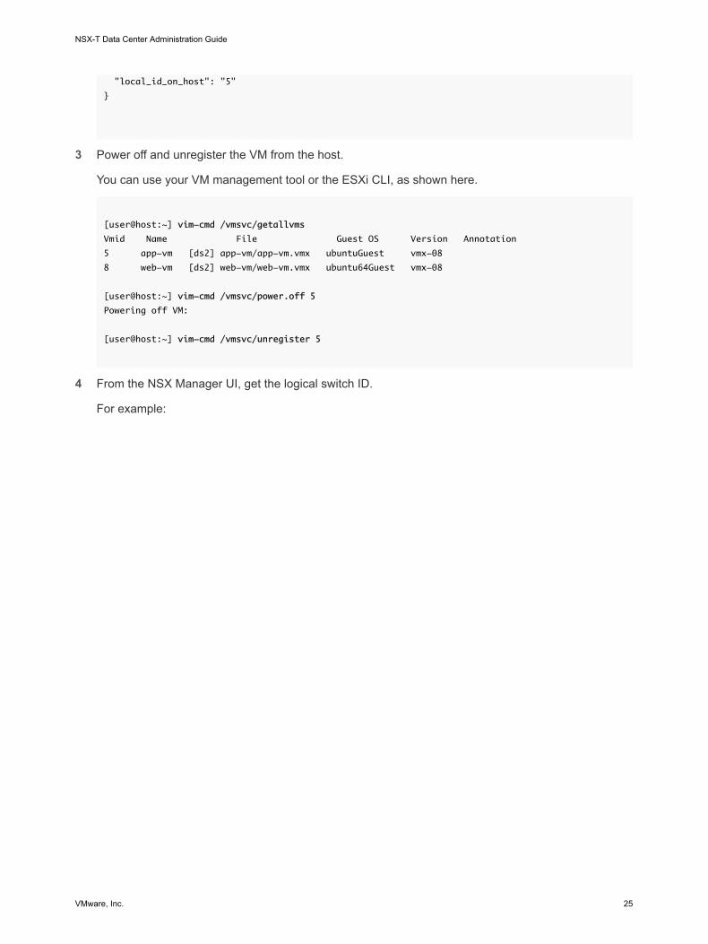
3 Power off and unregister the VM from the host.
You can use your VM management tool or the ESXi CLI, as shown here.
[user@host:~] vim-cmd /vmsvc/getallvms
Vmid Name File Guest OS Version Annotation
5 app-vm [ds2] app-vm/app-vm.vmx ubuntuGuest vmx-08
8 web-vm [ds2] web-vm/web-vm.vmx ubuntu64Guest vmx-08
[user@host:~] vim-cmd /vmsvc/power.off 5
Powering off VM:
[user@host:~] vim-cmd /vmsvc/unregister 5
4 From the NSX Manager UI, get the logical switch ID.
For example:
NSX-T Data Center Administration Guide
VMware, Inc. 25

5 Modify the VM's VMX file.
Delete the ethernet1.networkName = "<name>" field and add the following fields:
n ethernet1.opaqueNetwork.id = "<logical switch's ID>"
n ethernet1.opaqueNetwork.type = "nsx.LogicalSwitch"
n ethernet1.externalId = "<VM's externalId>"
n ethernet1.connected = "TRUE"
n ethernet1.startConnected = "TRUE"
For example:
OLD
ethernet1.pciSlotNumber = "224"
ethernet1.virtualDev = "vmxnet3"
ethernet1.networkName = "VM Network"
ethernet1.addressType = "vpx"
NSX-T Data Center Administration Guide
VMware, Inc. 26

ethernet1.generatedAddress = "00:50:56:86:7b:d7"
ethernet1.uptCompatibility = "true"
ethernet1.present = "TRUE"
NEW
ethernet1.pciSlotNumber = "224"
ethernet1.virtualDev = "vmxnet3"
ethernet1.addressType = "vpx"
ethernet1.generatedAddress = "00:50:56:86:7b:d7"
ethernet1.uptCompatibility = "true"
ethernet1.present = "TRUE"
ethernet1.opaqueNetwork.id = "22b22448-38bc-419b-bea8-b51126bec7ad"
ethernet1.opaqueNetwork.type = "nsx.LogicalSwitch"
ethernet1.externalId = "50066bae-0f8a-386b-e62e-b0b9c6013a51"
ethernet1.connected = "TRUE"
ethernet1.startConnected = "TRUE"
6 In the NSX Manager UI, add a logical switch port, and use the VM's externalId for the VIF attachment.
7 Reregister the VM and power it on.
You can use your VM management tool or the ESXi CLI, as shown here.
[user@host:~] vim-cmd /solo/register /path/to/file.vmx
For example:
[user@host:~] vim-cmd solo/registervm /vmfs/volumes/355f2049-6c704347/app-vm/app-vm.vmx
9
[user@host:~] vim-cmd /vmsvc/power.on 9
Powering on VM:
In the NSX Manager UI under Switching > Ports, find the VIF attachment ID matching the VM's externalId and make sure that the Admin and Operational status are Up/Up.
If two VMs are attached to the same logical switch and have IP addresses configured in the same subnet, they should be able to ping each other.
What to do next
Add a logical router.
You can monitor the activity on the logical switch port to troubleshoot problems. See "Monitor a Logical Switch Port Activity" in the NSX-T Data Center Administration Guide.
NSX-T Data Center Administration Guide
VMware, Inc. 27

Attach a VM Hosted on KVM to an NSX-T Data Center Logical SwitchIf you have a KVM host, you can use this procedure to attach VMs to NSX-T Data Center logical switches.
The example shown in this procedure shows how to attach a VM called app-vm to a logical switch called app-switch.
VM VM
172.16.20.10
App1VM
App2VM
App logical switch
172.16.20.11
Prerequisites
n The VM must be hosted on hypervisors that have been added to the NSX-T Data Center fabric.
n The fabric nodes must have NSX-T Data Center management plane (MPA) and NSX-T Data Center control plane (LCP) connectivity.
n The fabric nodes must be added to a transport zone.
n A logical switch must be created.
Procedure
1 From the KVM CLI, run the virsh dumpxml <your vm> | grep interfaceid command.
2 In the NSX Manager UI, add a logical switch port, and use the VM's interface ID for the VIF attachment.
In the NSX Manager UI under Switching > Ports, find the VIF attachment ID and make sure that the Admin and Operational status are Up/Up.
If two VMs are attached to the same logical switch and have IP addresses configured in the same subnet, they should be able to ping each other.
What to do next
Add a logical router.
NSX-T Data Center Administration Guide
VMware, Inc. 28

You can monitor the activity on the logical switch port to troubleshoot problems. See "Monitor a Logical Switch Port Activity" in the NSX-T Data Center Administration Guide.
Test Layer 2 ConnectivityAfter you successfully set up your logical switch and attach VMs to the logical switch, you can test the network connectivity of the attached VMs.
If your network environment is configured properly, based on the topology the App2 VM can ping the App1 VM.
Figure 1-3. Logical Switch Topology
VM VM
172.16.20.10
App1VM
App2VM
App logical switch
172.16.20.11
Procedure
1 Log in to one of the VMs attached to the logical switch using SSH or the VM console.
For example, App2 VM 172.16.20.11.
2 Ping the second VM attached to the logical switch to test connectivity.
$ ping -c 2 172.16.20.10
PING 172.16.20.10 (172.16.20.10) 56(84) bytes of data.
64 bytes from 172.16.20.10: icmp_seq=1 ttl=63 time=0.982 ms
64 bytes from 172.16.20.10: icmp_seq=2 ttl=63 time=0.654 ms
64 bytes from 172.16.20.10: icmp_seq=3 ttl=63 time=0.791 ms
--- 172.16.20.10 ping statistics ---
2 packets transmitted, 2 received, 0% packet loss, time 1990ms
rtt min/avg/max/mdev = 0.654/0.809/0.902/0.104 ms
3 (Optional) Identify the problem that causes the ping to fail.
a Verify that the VM network settings are correct.
b Verify that the VM network adapter is connected to the correct logical switch.
NSX-T Data Center Administration Guide
VMware, Inc. 29

c Verify that the logical switch Admin status is UP.
d From the NSX Manager, select Switching > Switches.
NSX-T Data Center Administration Guide
VMware, Inc. 30

e Click the logical switch and note the UUID and VNI information.
f From the NSX Controller, run the following commands to troubleshoot the problem.
Command Description
get logical-switch <vni-or-
uuid> arp-table
Displays the ARP table for the specified logical switch.
Sample output.
nsx-controller1> get logical-switch 41866 arp-tableVNI IP MAC Connection-ID 41866 172.16.20.11 00:50:56:b1:70:5e 295422
get logical-switch <vni-or-
uuid> connection-table
Displays the connections for the specified logical switch.
Sample output.
nsx-controller1> get logical-switch 41866 connection-tableHost-IP Port ID192.168.110.37 36923 295420192.168.210.53 37883 295421192.168.210.54 57278 295422
get logical-switch <vni-or-
uuid> mac-table
Displays the MAC table for the specified logical switch.
Sample output.
nsx-controller1> get logical-switch 41866 mac-tableVNI MAC VTEP-IP Connection-ID41866 00:50:56:86:f2:b2 192.168.250.102 29542141866 00:50:56:b1:70:5e 192.168.250.101 295422
get logical-switch <vni-or-
uuid> stats
Displays statistics information about the specified logical switch.
Sample output.
nsx-controller1> get logical-switch 41866 statsupdate.member 11update.vtep 11update.mac 4update.mac.invalidate 0update.arp 7update.arp.duplicate 0query.mac 2query.mac.miss 0query.arp 9query.arp.miss 6
get logical-switch <vni-or-
uuid> stats-sample
Displays a summary of all logical switch statistics over time.
Sample output.
nsx-controller1> get logical-switch 41866 stats-sample21:00:00 21:10:00 21:20:00 21:30:00 21:40:00update.member 0 0 0 0 0update.vtep 0 0 0 0 0update.mac 0 0 0 0 0update.mac.invalidate 0 0 0 0 0update.arp 0 0 0 0 0update.arp.duplicate 0 0 0 0 0
NSX-T Data Center Administration Guide
VMware, Inc. 31

Command Description
query.mac 0 0 0 0 0query.mac.miss 0 0 0 0 0query.arp 0 0 0 0 0query.arp.miss 0 0 0 0 0
get logical-switch <vni-or-
uuid> vtep
Displays all virtual tunnel end points related to the specified logical switch.
Sample output.
nsx-controller1> get logical-switch 41866 vtepVNI IP LABEL Segment MAC Connection-ID41866 192.168.250.102 0x8801 192.168.250.0 00:50:56:65:f5:fc 29542141866 192.168.250.100 0x1F801 192.168.250.0 02:50:56:00:00:00 29542041866 192.168.250.101 0x16001 192.168.250.0 00:50:56:64:7c:28 295422
The first VM attached to the logical switch is able to send packets to the second VM.
NSX-T Data Center Administration Guide
VMware, Inc. 32
Logical Switch Port 2A logical switch has multiple switch ports. Entities such as routers, VMs, or containers can connect to a logical switch through the logical switch ports.
This chapter includes the following topics:
n Create a Logical Switch Port
n Monitor a Logical Switch Port Activity
Create a Logical Switch PortA logical switch port lets you connect another network component, a VM, or a container to a logical switch.
For more information about connecting a VM to a logical switch, see Connecting a VM to a Logical Switch. For more information about connecting a container to a logical switch, see the NSX-T Container Plug-in for Kubernetes - Installation and Administration Guide.
Note The IP address and MAC address bound to a logical switch port for a container are allocated by NSX Manager. Do not change the address binding manually.
Prerequisites
Verify that a logical switch port is created. See Chapter 1 Logical Switches and Configuring VM Attachment.
Procedure
1 From your browser, log in with admin privileges to an NSX Manager at https://nsx-manager-ip-address.
2 Select Networking > Switching from the navigation panel.
3 Click the Ports tab.
4 Click Add.
5 In the General tab, complete the port details.
Option Description
Name and Description Enter a name and optionally a description.
Logical Switch Select a logical switch from the drop-down list.
VMware, Inc. 33

Option Description
Admin Status Select Up or Down.
Attachment Type Select None or VIF.
Attachment ID If the attachment type is VIF, enter the attachment ID.
6 (Optional) In the Switching Profiles tab, select switching profiles.
7 Click Save.
Monitor a Logical Switch Port ActivityYou can monitor the logical port activity for example, to troubleshoot network congestion and packets being dropped
Prerequisites
Verify that a logical switch port is configured. See Connecting a VM to a Logical Switch.
Procedure
1 From your browser, log in with admin privileges to an NSX Manager at https://nsx-manager-ip-address.
2 Select Networking > Switching from the navigation panel.
3 Click the Ports tab.
4 Click the name of a port.
5 Click the Monitor tab.
The port status and statistics are displayed.
6 To download a CSV file of the MAC addresses that has been learned by the host, click Download MAC Table.
7 To monitor activity on the port, click Begin Tracking.
A port tracking page opens. You can view the bidirectional port traffic and identify dropped packets. The port tracker page also lists the switching profiles attached to the logical switch port.
If you notice dropped packets because of network congestion, you can configure a QoS switching profile for the logical switch port to prevent data loss on preferred packets. See Understanding QoS Switching Profile.
NSX-T Data Center Administration Guide
VMware, Inc. 34

Switching Profiles for Logical Switches and Logical Ports 3Switching profiles include Layer 2 networking configuration details for logical switches and logical ports. NSX Manager supports several types of switching profiles, and maintains one or more system-defined default switching profiles for each profile type.
The following types of switching profiles are available.
n QoS (Quality of Service)
n IP Discovery
n SpoofGuard
n Switch Security
n MAC Management
Note You cannot edit or delete the default switching profiles in the NSX Manager. You can create custom switching profiles instead.
Each default or custom switching profile has a unique reserved identifier. You use this identifier to associate the switching profile to a logical switch or a logical port. For example, the default QoS switching profile ID is f313290b-eba8-4262-bd93-fab5026e9495.
A logical switch or logical port can be associated with one switching profile of each type. You cannot have for example, two QoS different switching profiles associated to a logical switch or logical port.
If you do not associate a switching profile type while creating or updating a logical switch, then the NSX Manager associates a corresponding default system-defined switching profile. The children logical ports inherit the default system-defined switching profile from the parent logical switch.
When you create or update a logical switch or logical port you can choose to associate either a default or a custom switching profile. When the switching profile is associated or disassociated from a logical switch the switching profile for the children logical ports is applied based on the following criteria.
n If the parent logical switch has a profile associated with it, the child logical port inherits the switching profile from the parent.
n If the parent logical switch does not have a switching profile associated with it, a default switching profile is assigned to the logical switch and the logical port inherits that default switching profile.
VMware, Inc. 35

n If you explicitly associate a custom profile with a logical port, then this custom profile overrides the existing switching profile.
Note If you have associated a custom switching profile with a logical switch, but want to retain the default switching profile for one of the child logical port, then you must make a copy of the default switching profile and associate it with the specific logical port.
You cannot delete a custom switching profile if it is associated to a logical switch or a logical port. You can find out whether any logical switches and logical ports are associated with the custom switching profile by going to the Assigned To section of the Summary view and clicking on the listed logical switches and logical ports.
This chapter includes the following topics:
n Understanding QoS Switching Profile
n Understanding IP Discovery Switching Profile
n Understanding SpoofGuard
n Understanding Switch Security Switching Profile
n Understanding MAC Management Switching Profile
n Associate a Custom Profile with a Logical Switch
n Associate a Custom Profile with a Logical Port
Understanding QoS Switching ProfileQoS provides high-quality and dedicated network performance for preferred traffic that requires high bandwidth. The QoS mechanism does this by prioritizing sufficient bandwidth, controlling latency and jitter, and reducing data loss for preferred packets even when there is a network congestion. This level of network service is provided by using the existing network resources efficiently.
For this release, shaping and traffic marking namely, CoS and DSCP is supported. The Layer 2 Class of Service (CoS) allows you to specify priority for data packets when traffic is buffered in the logical switch due to congestion. The Layer 3 Differentiated Services Code Point (DSCP) detects packets based on their DSCP values. CoS is always applied to the data packet irrespective of the trusted mode.
NSX-T Data Center trusts the DSCP setting applied by a virtual machine or modifying and setting the DSCP value at the logical switch level. In each case, the DSCP value is propagated to the outer IP header of encapsulated frames. This enables the external physical network to prioritize the traffic based on the DSCP setting on the external header. When DSCP is in the trusted mode, the DSCP value is copied from the inner header. When in the untrusted mode, the DSCP value is not preserved for the inner header.
Note DSCP settings work only on tunneled traffic. These settings do not apply to traffic inside the same hypervisor.
NSX-T Data Center Administration Guide
VMware, Inc. 36

You can use the QoS switching profile to configure the average ingress and egress bandwidth values to set the transmit limit rate. The peak bandwidth rate is used to support burst traffic a logical switch is allowed to prevent congestion on the northbound network links. These settings do not guarantee the bandwidth but help limit the use of network bandwidth. The actual bandwidth you will observe is determined by the link speed of the port or the values in the switching profile, whichever is lower.
The QoS switching profile settings are applied to the logical switch and inherited by the child logical switch port.
Configure a Custom QoS Switching ProfileYou can define the DSCP value and configure the ingress and egress settings to create a custom QoS switching profile.
Prerequisites
n Familiarize yourself with the QoS switching profile concept. See Understanding QoS Switching Profile.
n Identify the network traffic you want to prioritize.
Procedure
1 From your browser, log in with admin privileges to an NSX Manager at https://nsx-manager-ip-address.
2 Select Networking > Switching from the navigation panel.
3 Click the Switching Profiles tab.
4 Click Add and select QoS.
5 Complete the QoS switching profile details.
Option Description
Name and Description Assign a name to the custom QoS switching profile.
You can optionally describe the setting that you modified in the profile.
Mode Select either a Trusted or Untrusted option from the Mode drop-down menu.
When you select the Trusted mode the inner header DSCP value is applied to the outer IP header for IP/IPv6 traffic. For non IP/IPv6 traffic, the outer IP header takes the default value. Trusted mode is supported on an overlay-based logical port. The default value is 0.
Untrusted mode is supported on overlay-based and VLAN-based logical port. For the overlay-based logical port, the DSCP value of the outbound IP header is set to the configured value irrespective to the inner packet type for the logical port. For the VLAN-based logical port, the DSCP value of IP/IPv6 packet will be set to the configured value. The DSCP values range for untrusted mode is between 0 to 63.
Note DSCP settings work only on tunneled traffic. These settings do not apply to traffic inside the same hypervisor.
Priority Set the CoS priority value.
The priority values range from 0 to 63, where 0 has the highest priority.
NSX-T Data Center Administration Guide
VMware, Inc. 37

Option Description
Class of Service Set the CoS value.
CoS is supported on VLAN-based logical port. CoS groups similar types of traffic in the network and each type of traffic is treated as a class with its own level of service priority. The lower priority traffic is slowed down or in some cases dropped to provide better throughput for higher priority traffic. CoS can also be configured for the VLAN ID with zero packet.
The CoS values range from 0 to 7, where 0 is the best effort service.
Ingress Set custom values for the outbound network traffic from the VM to the logical network.
You can use the average bandwidth to reduce network congestion. The peak bandwidth rate is used to support burst traffic and the burst duration is set in the burst size setting. You cannot guarantee the bandwidth. However, you can use the setting to limit network bandwidth. The default value 0, disables the ingress traffic.
For example, when you set the average bandwidth for the logical switch to 30 Mbps the policy limits the bandwidth. You can cap the burst traffic at 100 Mbps for a duration 20 Bytes.
Ingress Broadcast Set custom values for the outbound network traffic from the VM to the logical network based on broadcast.
The default value 0, disables the ingress broadcast traffic.
For example, when you set the average bandwidth for a logical switch to 50 Kbps the policy limits the bandwidth. You can cap the burst traffic to 400 Kbps for a duration of 60 Bytes.
Egress Set custom values for the inbound network traffic from the logical network to the VM.
The default value 0, disables the egress traffic. If the ingress, ingress broadcast, and egress options are not configured, the default values are used as protocol buffers.
6 Click Save.
A custom QoS switching profile appears as a link.
What to do next
Attach this QoS customized switching profile to a logical switch or logical port so that the modified parameters in the switching profile are applied to the network traffic. See Associate a Custom Profile with a Logical Switch or Associate a Custom Profile with a Logical Port.
Understanding IP Discovery Switching ProfileIP Discovery uses DHCP snooping, ARP snooping, or VM Tools to learn the VM MAC and IP addresses. After the MAC and IP addresses are learnt, the entries are shared with the NSX Controller to achieve ARP suppression. ARP suppression minimizes ARP traffic flooding within VMs connected to the same logical switch.
DHCP snooping inspects the DHCP packets exchanged between the VM DHCP client and the DHCP server to learn the VM IP and MAC addresses.
NSX-T Data Center Administration Guide
VMware, Inc. 38

ARP snooping inspects the outgoing ARPs and GARPs of the VM to learn the IP and MAC addresses.
VM Tools is software that runs on an ESXi-hosted VM and can provide the VM's configuration information including MAC and IP addresses. This IP discovery method is available for VMs running on ESXi hosts only.
Note For Linux VMs, the ARP flux problem might cause ARP snooping to obtain incorrect information. The problem can be prevented with an ARP filter. For more information, see http://linux-ip.net/html/ether-arp.html#ether-arp-flux.
Configure IP Discovery Switching ProfileYou can enable the ARP snooping, DHCP snooping, or VM Tools to create a custom IP Discovery switching profile that learns the IP and MAC addresses to ensure the IP integrity of a logical switch. The VM Tools IP discovery method is available for ESXi-hosted VMs only.
Prerequisites
Familiarize yourself with the IP Discovery switching profile concept. See Understanding IP Discovery Switching Profile.
Procedure
1 From your browser, log in with admin privileges to an NSX Manager at https://nsx-manager-ip-address.
2 Select Networking > Switching from the navigation panel.
3 Click the Switching Profiles tab.
4 Click Add and select IP Discovering.
5 Complete the IP Discovery switching profile details.
Option Description
Name and Description Enter a name and optionally a description.
ARP Snooping Toggle the ARP Snooping button to enable the feature.
ARP snooping inspects the VM outgoing ARP and GARP to learn the VM MAC and IP addresses. ARP snooping is applicable if the VM uses a static IP address instead of DHCP.
ARP Binding Limit Specify an ARP binding limit from 1 to 128.
DHCP Snooping Toggle the DHCP Snooping button to enable the feature.
DHCP snooping inspects the DHCP packets exchanged between the VM DHCP client and the DHCP server, to learn the VM MAC and IP addresses.
VM Tools Toggle the VM Tools button to enable the feature. This option is available for ESXi-hosted VMs only.
VM Tools is software that runs on an ESXi-hosted VM and can provide the VM's MAC and IP addresses.
6 Click Save.
NSX-T Data Center Administration Guide
VMware, Inc. 39

A custom IP Discovery switching profile appears as a link.
What to do next
Attach this IP Discovery customized switching profile to a logical switch or logical port so that the modified parameters in the switching profile are applied to the network traffic. See Associate a Custom Profile with a Logical Switch or Associate a Custom Profile with a Logical Port.
Understanding SpoofGuardSpoofGuard helps prevent a form of malicious attack called "web spoofing" or "phishing." A SpoofGuard policy blocks traffic determined to be spoofed.
SpoofGuard is a tool that is designed to prevent virtual machines in your environment from sending traffic with an IP address it is not authorized to end traffic from. In the instance that a virtual machine’s IP address does not match the IP address on the corresponding logical port and switch address binding in SpoofGuard, the virtual machine’s vNIC is prevented from accessing the network entirely. SpoofGuard can be configured at the port or switch level. There are several reasons SpoofGuard might be used in your environment:
n Preventing a rogue virtual machine from assuming the IP address of an existing VM.
n Ensuring the IP addresses of virtual machines cannot be altered without intervention – in some environments, it’s preferable that virtual machines cannot alter their IP addresses without proper change control review. SpoofGuard facilitates this by ensuring that the virtual machine owner cannot simply alter the IP address and continue working unimpeded.
n Guaranteeing that distributed firewall (DFW) rules will not be inadvertently (or deliberately) bypassed – for DFW rules created utilizing IP sets as sources or destinations, the possibility always exists that a virtual machine could have it’s IP address forged in the packet header, thereby bypassing the rules in question.
NSX-T Data Center SpoofGuard configuration covers the following:
n MAC SpoofGuard - authenticates MAC address of packet
n IP SpoofGuard - authenticates MAC and IP addresses of packet
n Dynamic Address Resolution Protocol (ARP) inspection, that is, ARP and Gratuitous Address Resolution Protocol (GARP) SpoofGuard and Neighbor Discovery (ND) SpoofGuard validation are all against the MAC source, IP Source and IP-MAC source mapping in the ARP/GARP/ND payload.
At the port level, the allowed MAC/VLAN/IP whitelist is provided through the Address Bindings property of the port. When the virtual machine sends traffic, it is dropped if its IP/MAC/VLAN does not match the IP/MAC/VLAN properties of the port. The port level SpoofGuard deals with traffic authentication, i.e. is the traffic consistent with VIF configuration.
At the switch level, the allowed MAC/VLAN/IP whitelist is provided through the Address Bindings property of the switch. This is typically an allowed IP range/subnet for the switch and the switch level SpoofGuard deals with traffic authorization.
NSX-T Data Center Administration Guide
VMware, Inc. 40

Traffic must be permitted by port level AND switch level SpoofGuard before it will be allowed into switch. Enabling or disabling port and switch level SpoofGuard, can be controlled using the SpoofGuard switch profile.
Configure Port Address BindingsAddress bindings specify the IP and MAC address of a logical port and are used to specify the port whitelist in SpoofGuard.
With port address bindings you'll specify the IP and MAC address, and VLAN if applicable, of the logical port. When SpoofGuard is enabled, it ensures that the specified address bindings are enforced in the data path. In addition to SpoofGuard, port address bindings are used for DFW rule translations.
Procedure
1 In NSX Manager, navigate to Networking > Switching.
2 Click the Ports tab.
3 Click the logical port to which you want apply address binding.
The logical port summary appears.
4 In the Overview tab, expand Address Bindings.
5 Click Add.
The Add Address Binding dialogue box appears
6 Specify the IP and MAC address of the logical port to which you want to apply address binding. You can also specify a VLAN ID.
7 Click Add.
What to do next
Use the port address bindings when you Configure a SpoofGuard Switching Profile.
Configure a SpoofGuard Switching ProfileWhen SpoofGuard is configured, if the IP address of a virtual machine changes, traffic from the virtual machine may be blocked until the corresponding configured port/switch address bindings are updated with the new IP address.
Enable SpoofGuard for the port group(s) containing the guests. When enabled for each network adapter, SpoofGuard inspects packets for the prescribed MAC and its corresponding IP address.
Procedure
1 From your browser, log in with admin privileges to an NSX Manager at https://nsx-manager-ip-address.
2 Select Networking > Switching from the navigation panel.
3 Click the Switching Profiles tab.
NSX-T Data Center Administration Guide
VMware, Inc. 41

4 Click Add and select Spoof Guard.
5 Enter a name and optionally a description.
6 To enable port level SpoofGuard, set Port Bindings to Enabled.
7 Click Add.
A new switching profile has been created with a SpoofGuard Profile.
What to do next
Associate the SpoofGuard profile with a logical switch or logical port. See Associate a Custom Profile with a Logical Switch or Associate a Custom Profile with a Logical Port.
Understanding Switch Security Switching ProfileSwitch security provides stateless Layer2 and Layer 3 security by checking the ingress traffic to the logical switch and dropping unauthorized packets sent from VMs by matching the IP address, MAC address, and protocols to a set of allowed addresses and protocols. You can use switch security to protect the logical switch integrity by filtering out malicious attacks from the VMs in the network.
You can configure the Bridge Protocol Data Unit (BPDU) filter, DHCP Snooping, DHCP server block, and rate limiting options to customize the switch security switching profile on a logical switch.
Configure a Custom Switch Security Switching ProfileYou can create a custom switch security switching profile with MAC destination addresses from the allowed BPDU list and configure rate limiting.
Prerequisites
Familiarize yourself with the switch security switching profile concept. See Understanding Switch Security Switching Profile.
Procedure
1 From your browser, log in with admin privileges to an NSX Manager at https://nsx-manager-ip-address.
2 Select Networking > Switching from the navigation panel.
3 Click the Switching Profiles tab.
4 Click Add and select Switch Security.
NSX-T Data Center Administration Guide
VMware, Inc. 42

5 Complete the switch security profile details.
Option Description
Name and Description Assign a name to the custom switch security profile.
You can optionally describe the setting that you modified in the profile.
BPDU Filter Toggle the BPDU filter button to enable BPDU filtering.
When the BPDU filter is enabled, all of the traffic to BPDU destination MAC address is blocked. The BPDU filter when enabled also disables STP on the logical switch ports because these ports are not expected to take part in STP.
BPDU Filter Allow List Click the destination MAC address from the BPDU destination MAC addresses list to allow traffic to the permitted destination.
DHCP Filter Toggle the Server Block button and Client Block button to enable DHCP filtering.
DHCP Server Block blocks traffic from a DHCP server to a DHCP client. Note that it does not block traffic from a DHCP server to a DHCP relay agent.
DHCP Client Block prevents a VM from acquiring a DHCP IP address by blocking DHCP requests.
Block Non-IP Traffic Toggle the Block Non-IP Traffic button to allow only IPv4, IPv6, ARP, GARP and BPDU traffic.
The rest of the non-IP traffic is blocked. The permitted IPv4, IPv6, ARP, GARP and BPDU traffic is based on other policies set in address binding and SpoofGuard configuration.
By default, this option is disabled to allow non-IP traffic to be handled as regular traffic.
Rate Limits Set a rate limit for the ingress or egress Broadcast and Multicast traffic.
Rate limits are configured to protect the logical switch or the VM from for example, broadcast traffic storms.
To avoid any connectivity problems, the minimum rate limit value must be >= 10 pps.
6 Click Add.
A custom switch security profile appears as a link.
What to do next
Attach this switch security customized switching profile to a logical switch or logical port so that the modified parameters in the switching profile are applied to the network traffic. See Associate a Custom Profile with a Logical Switch or Associate a Custom Profile with a Logical Port.
Understanding MAC Management Switching ProfileThe MAC management switching profile supports two functionalities: MAC learning and MAC address change.
The MAC address change feature allows a VM to change its MAC address. A VM connected to a port can run an administrative command to change the MAC address of its vNIC and still send and receive traffic on that vNIC. This feature is supported on ESXi only and not on KVM. This property is disabled by default.
NSX-T Data Center Administration Guide
VMware, Inc. 43

MAC learning provides network connectivity to deployments where multiple MAC addresses are configured behind one vNIC, for example, in a nested hypervisor deployment where an ESXi VM runs on an ESXi host and multiple VMs run inside the ESXi VM. Without MAC learning, when the ESXi VM's vNIC connects to a switch port, its MAC address is static. VMs running inside the ESXi VM do not have network connectivity because their packets have different source MAC addresses. With MAC learning, the vSwitch inspects the source MAC address of every packet coming from the vNIC, learns the MAC address and allows the packet to go through. If a MAC address that is learned is not used for a certain period of time, it is removed. This aging property is not configurable.
If you enable MAC learning or MAC address change, to improve security, configure SpoofGuard as well.
Configure MAC Management Switching ProfileYou can create a MAC management switching profile to manage MAC addresses.
Prerequisites
Familiarize yourself with the MAC management switching profile concept. See Understanding MAC Management Switching Profile.
Procedure
1 From your browser, log in with admin privileges to an NSX Manager at https://nsx-manager-ip-address.
2 Select Networking > Switching from the navigation panel.
3 Click the Switching Profiles tab.
4 Click Add and select MAC Management.
5 Complete the MAC management profile details.
Option Description
Name and Description Assign a name to the MAC management profile.
You can optionally describe the setting that you modified in the profile.
MAC Change Enable or disable the MAC address change feature.
Status Enable or disable the MAC learning feature.
6 Click Add.
A MAC management profile appears as a link.
What to do next
Attach the switching profile to a logical switch or logical port. See Associate a Custom Profile with a Logical Switch or Associate a Custom Profile with a Logical Port.
NSX-T Data Center Administration Guide
VMware, Inc. 44

Associate a Custom Profile with a Logical SwitchYou can associate a custom switching profile to a logical switch so that the profile applies to all the ports on the switch.
When custom switching profiles are attached to a logical switch they override existing default switching profiles. The custom switching profile is inherited by children logical switch ports.
Note If you have associated a custom switching profile with a logical switch, but want to retain the default switching profile for one of the child logical switch port, then you must make a copy of the default switching profile and associate it with the specific logical switch port.
Prerequisites
n Verify that a logical switch is configured. See Create a Logical Switch.
n Verify that a custom switching profile is configured. See Chapter 3 Switching Profiles for Logical Switches and Logical Ports.
Procedure
1 From your browser, log in with admin privileges to an NSX Manager at https://nsx-manager-ip-address.
2 Select Networking > Switching from the navigation panel.
3 Click the Switches tab.
4 Click the logical switch to apply the custom switching profile.
5 Click the Manage tab.
6 Select the custom switching profile type from the drop-down menu.
n QoS
n Port Mirroring
n IP Discovering
n SpoofGuard
n Switch Security
n MAC Management
7 Click Change.
8 Select the previously created custom switching profile from the drop-down menu.
9 Click Save.
The logical switch is now associated with the custom switching profile.
10 Verify that the new custom switching profile with the modified configuration appears under the Manage tab.
NSX-T Data Center Administration Guide
VMware, Inc. 45

11 (Optional) Click the Related tab and select Ports from the drop-down menu to verify that the custom switching profile is applied to child logical ports.
What to do next
If you do not want to use the inherited switching profile from a logical switch, you can apply a custom switching profile to the child logical switch port. See Associate a Custom Profile with a Logical Port.
Associate a Custom Profile with a Logical PortA logical port provides a logical connection point for a VIF, a patch connection to a router, or a Layer 2 gateway connection to an external network. Logical ports also expose switching profiles, port statistics counters, and a logical link status.
You can change the inherited switching profile from the logical switch to a different custom switching profile for the child logical port.
Prerequisites
n Verify that a logical port is configured. See Connecting a VM to a Logical Switch.
n Verify that a custom switching profile is configured. See Chapter 3 Switching Profiles for Logical Switches and Logical Ports.
Procedure
1 From your browser, log in with admin privileges to an NSX Manager at https://nsx-manager-ip-address.
2 Select Networking > Switching from the navigation panel.
3 Click the Ports tab.
4 Click the logical port to apply the custom switching profile.
5 Click the Manage tab.
6 Select the custom switching profile type from the drop-down menu.
n QoS
n Port Mirroring
n IP Discovering
n SpoofGuard
n Switch Security
n MAC Management
7 Click Change.
8 Select the previously created custom switching profile from the drop-down menu.
NSX-T Data Center Administration Guide
VMware, Inc. 46

9 Click Save.
The logical port is now associated with the custom switching profile.
10 Verify that the new custom switching profile with the modified configuration appears under the Manage tab.
What to do next
You can monitor the activity on the logical switch port to troubleshoot problems. See "Monitor a Logical Switch Port Activity" in the NSX-T Data Center Administration Guide.
NSX-T Data Center Administration Guide
VMware, Inc. 47

Tier-1 Logical Router 4An NSX-T Data Center logical router reproduces routing functionality in a virtual environment completely decoupled from underlying hardware. Tier-1 logical routers have downlink ports to connect to NSX-T Data Center logical switches and uplink ports to connect to NSX-T Data Center tier-0 logical routers.
When you add a logical router, it is important that you plan the networking topology you are building.
Figure 4-1. Tier-1 Logical Router Topology
VM VM
172.16.20.10 172.16.10.10
appVM
webVM
tier-1
Host
Applogicalswitch
Weblogicalswitch
For example, this simple topology shows two logical switches connected to a tier-1 logical router. Each logical switch has a single VM connected. The two VMs can be on different hosts or the same host, in different host clusters or in the same host cluster. If a logical router does not separate the VMs, the underlying IP addresses configured on the VMs must be in the same subnet. If a logical router does separate them, the IP addresses on the VMs must be in different subnets.
This chapter includes the following topics:
n Create a Tier-1 Logical Router
n Add a Downlink Port on a Tier-1 Logical Router
n Add a VLAN Port on a Tier-0 or Tier-1 Logical Router
n Configure Route Advertisement on a Tier-1 Logical Router
VMware, Inc. 48

n Configure a Tier-1 Logical Router Static Route
n Create a Standalone Tier-1 Logical Router
Create a Tier-1 Logical RouterThe tier-1 logical router must be connected to the tier-0 logical router to get the northbound physical router access.
Prerequisites
n Verify that the logical switches are configured. See Create a Logical Switch.
n Verify that an NSX Edge cluster is deployed to perform network address translation (NAT) configuration. See the NSX-T Data Center Installation Guide.
n Familiarize yourself with the tier-1 logical router topology. See Chapter 4 Tier-1 Logical Router.
Procedure
1 From your browser, log in with admin privileges to an NSX Manager at https://nsx-manager-ip-address.
2 Select Networking > Routing from the navigation panel.
3 Click Add and select Tier-1 Router.
4 Enter a name for the logical router and optionally a description.
5 (Optional) Select a tier-0 logical router to connect to this tier-1 logical router.
If you do not yet have any tier-0 logical routers configured, you can leave this field blank for now and edit the router configuration later.
6 (Optional) Select an NSX Edge cluster to connect to this tier-1 logical router.
If the tier-1 logical router is going to be used for NAT configuration, it must be connected to an NSX Edge cluster. If you do not yet have any NSX Edge clusters configured, you can leave this field blank for now and edit the router configuration later.
7 (Optional) If you selected an NSX Edge cluster, select a failover mode.
Option Description
Preemptive If the preferred node fails and recovers, it will preempt its peer and become the active node. The peer will change its state to standby. This is the default option.
Non-preemptive If the preferred node fails and recovers, it will check if its peer is the active node. If so, the preferred node will not preempt its peer and will be the standby node.
8 (Optional) Click the Advanced tab and enter a value for Intra Tier-1 Transit Subnet.
9 Click Add.
In the NSX Manager UI, the new logical router is a clickable link.
NSX-T Data Center Administration Guide
VMware, Inc. 49

If this logical router supports more than 5000 VMs, you must run the following commands on each node of the NSX Edge cluster to increase the size of the ARP table.
set debug-mode
set dataplane neighbor max-arp-logical-router 10000
You must re-run the commands after a dataplane restart or a node reboot because the change is not persistent.
What to do next
Create downlink ports for your tier-1 logical router. See Add a Downlink Port on a Tier-1 Logical Router.
Add a Downlink Port on a Tier-1 Logical RouterWhen you create a downlink port on a tier-1 logical router, the port serves as a default gateway for the VMs that are in the same subnet.
Prerequisites
Verify that a tier-1 logical router is configured. See Create a Tier-1 Logical Router .
Procedure
1 From your browser, log in with admin privileges to an NSX Manager at https://nsx-manager-ip-address.
2 Select Networking > Routing from the navigation panel.
3 Click the name of a router.
4 Click the Configuration tab and select Router Ports.
5 Click Add.
6 Enter a name for the router port and optionally a description.
7 In the Type field, select Downlink.
8 For URPF Mode, select Strict or None.
URPF (unicast Reverse Path Forwarding) is a security feature.
9 (Optional) Select a logical switch.
10 Select whether this attachment creates a switch port or updates an existing switch port.
If the attachment is for an existing switch port, select the port from the drop-down menu.
11 Enter the router port IP address in CIDR notation.
For example, the IP address can be 172.16.10.1/24.
12 (Optional) Select a DHCP relay service.
13 Click Add.
NSX-T Data Center Administration Guide
VMware, Inc. 50

What to do next
Enable route advertisement to provide North-South connectivity between VMs and external physical networks or between different tier-1 logical routers that are connected to the same tier-0 logical router. See Configure Route Advertisement on a Tier-1 Logical Router.
Add a VLAN Port on a Tier-0 or Tier-1 Logical RouterIf you have only VLAN-backed logical switches, you can connect the switches to VLAN ports on a tier-0 or tier-1 router so that NSX-T Data Center can provide layer-3 services.
Procedure
1 From your browser, log in with admin privileges to an NSX Manager at https://nsx-manager-ip-address.
2 Select Networking > Routing from the navigation panel.
3 Click the name of a router.
4 Click the Configuration tab and select Router Ports.
5 Click Add.
6 Enter a name for the router port and optionally a description.
7 In the Type field, select Centralized.
8 For URPF Mode, select Strict or None.
URPF (unicast Reverse Path Forwarding) is a security feature.
9 (Required) Select a logical switch.
10 Select whether this attachment creates a switch port or updates an existing switch port.
If the attachment is for an existing switch port, select the port from the drop-down menu.
11 Enter the router port IP address in CIDR notation.
12 Click Add.
Configure Route Advertisement on a Tier-1 Logical RouterTo provide Layer 3 connectivity between VMs connected to logical switches that are attached to different tier-1 logical routers, it is necessary to enable tier-1 route advertisement towards tier-0. You do not need to configure a routing protocol or static routes between tier-1 and tier-0 logical routers. NSX-T Data Center creates NSX-T Data Center static routes automatically when you enable route advertisement.
For example, to provide connectivity to and from the VMs through other peer routers, the tier-1 logical router must have route advertisement configured for connected routes. If you don't want to advertise all connected routes, you can specify which routes to advertise.
NSX-T Data Center Administration Guide
VMware, Inc. 51

VM VM
172.16.20.1 172.16.10.1
172.16.20.10 172.16.10.10
applogicalswitch
appVM
webVM
tier-1 weblogicalswitch
Advertise connected routes
Host
Connected routes:172.16.10.0/24172.16.20.0/24
Prerequisites
n Verify that VMs are attached to logical switches. See Chapter 1 Logical Switches and Configuring VM Attachment.
n Verify that downlink ports for the tier-1 logical router are configured. See Add a Downlink Port on a Tier-1 Logical Router.
Procedure
1 From your browser, log in with admin privileges to an NSX Manager at https://nsx-manager-ip-address.
2 Select Networking > Routing from the navigation panel.
3 Click the name of a tier-1 router.
4 Select Route Advertisement from the Routing drop-down menu.
5 Click Edit to edit the route advertisement configuration.
You can toggle the following switches:
n Status
n Advertise All NSX Connected Routes
n Advertise All NAT Routes
n Advertise All Static Routes
NSX-T Data Center Administration Guide
VMware, Inc. 52

n Advertise All LB VIP Routes
n Advertise All LB SNAT IP Routes
a Click Save.
6 Click Add to advertise routes.
a Enter a name and optionally a description.
b Enter a route prefix in CIDR format.
c Click Apply Filter to set the following options:
Action Specify Allow or Deny.
Match route types Select one or more of the following:
n Anyn NSX Connectedn Tier-1 LB VIPn Staticn Tier-1 NATn Tier-1 LB SNAT
Prefix operator Select GE or EQ.
d Click Add.
What to do next
Familiarize yourself with the tier-0 logical router topology and create the tier-0 logical router. See Chapter 5 Tier-0 Logical Router.
If you already have a tier-0 logical router connected to the tier-1 logical router, you can verify that the tier-0 router is learning the tier-1 router connected routes. See Verify that a Tier-0 Router Has Learned Routes from a Tier-1 Router.
Configure a Tier-1 Logical Router Static RouteYou can configure a static route on a tier-1 logical router to provide connectivity from NSX-T Data Center to a set of networks that are accessible through a virtual router.
For example, in the following diagram, the tier-1 A logical router has a downlink port to an NSX-T Data Center logical switch. This downlink port (172.16.40.1) serves the default gateway for the virtual router VM. The virtual router VM and tier-1 A are connected through the same NSX-T Data Center logical switch. The tier-1 logical router has a static route 10.10.0.0/16 that summarizes the networks available through the virtual router. Tier-1 A then has route advertisement configured to advertise the static route to tier-1 B.
NSX-T Data Center Administration Guide
VMware, Inc. 53

Figure 4-2. Tier-1 Logical Router Static Route Topology
VMVM VM
172.16.40.1
172.16.40.10
172.16.10.11
logicalswitch 1
tier-0
Static route to10.10.0.0/16
tier-1B
tier-1A
172.16.10.1
logicalswitch 2
VirtualrouterVM
10.10.20.0/2410.10.10.0/24
Prerequisites
Verify that a downlink port is configured. See Add a Downlink Port on a Tier-1 Logical Router.
Procedure
1 From your browser, log in with admin privileges to an NSX Manager at https://nsx-manager-ip-address.
2 Select Networking > Routing from the navigation panel.
3 Click the name of a tier-1 router.
4 Click the Routing tab and select Static Routes from the drop-down menu.
5 Click Add.
6 Enter a network address in the CIDR format.
For example, 10.10.10.0/16.
7 Click Add to add a next-hop IP address.
For example, 172.16.40.10. You can also specify a null route by clicking the pencil icon and selecting NULL from the drop-down. To add another next hop addresses, click Add again.
NSX-T Data Center Administration Guide
VMware, Inc. 54

8 Click Add at the bottom of the dialog box.
The newly created static route network address appears in the row.
9 From the tier-1 logical router, select Routing > Route Advertisement.
10 Click Edit and select Advertise All Static Routes.
11 Click Save.
The static route is propagated across the NSX-T Data Center overlay.
Create a Standalone Tier-1 Logical RouterA standalone tier-1 logical router has no downlink and no connection to a tier-0 router. It has a service router but no distributed router. The service router can be deployed on one NSX Edge node or two NSX Edge nodes in active-standby mode.
A standalone tier-1 logical router:
n Must not have a connection to a tier-0 logical router.
n Must not have a downlink.
n Can have only one centralized service port (CSP) if it is used to attach a load balancer (LB) service.
n Can connect to an overlay logical switch or a VLAN logical switch.
n Supports the load balancing and NAT services only.
Typically, a standalone tier-1 logical router is connected to a logical switch that a regular tier-1 logical router is also connected to. The standalone tier-1 logical router can communicate with other devices through the regular tier-1 logical router after static routes and route advertisements are configured.
Procedure
1 From your browser, log in with admin privileges to an NSX Manager at https://nsx-manager-ip-address.
2 Select Networking > Routing from the navigation panel.
3 Click Add and select Tier-1 Router.
4 Enter a name for the logical router and optionally a description.
5 (Required) Select an NSX Edge cluster to connect to this tier-1 logical router.
6 (Required) Select a failover mode and cluster members.
Option Description
Preemptive If the preferred node fails and recovers, it will preempt its peer and become the active node. The peer will change its state to standby. This is the default option.
Non-preemptive If the preferred node fails and recovers, it will check if its peer is the active node. If so, the preferred node will not preempt its peer and will be the standby node.
7 Click Add.
NSX-T Data Center Administration Guide
VMware, Inc. 55

8 Click the name of the router that you just created.
9 Click the Configuration tab and select Router Ports.
10 Click Add.
11 Enter a name for the router port and optionally a description.
12 In the Type field, select Centralized.
13 For URPF Mode, select Strict or None.
URPF (Unicast Reverse Path Forwarding) is a security feature.
14 (Required) Select a logical switch.
15 Select whether this attachment creates a switch port or updates an existing switch port.
16 Enter the router port IP address in CIDR notation.
17 Click Add.
Before using the standalone tier-1 logical router, note the following:
n To specify the default gateway for the standalone tier-1 logical router, you must add a static route. The subnet should be 0.0.0.0/0 and the next hop is the IP address of a regular tier-1 router connected to the same switch.
n ARP proxy on the standalone router is not supported. Therefore, you must not configure an LB virtual server IP or LB SNAT IP in the CSP's subnet unless you use the CSP IP. For example, if the CSP IP is 1.1.1.1/24, the virtual IP must be either 1.1.1.1 or some other subnet IP addresses. It cannot be any other address in the 1.1.1.1/24 subnet.
n For an NSX Edge VM, you cannot have more than one CSPs which are connected to the same VLAN-backed logical switch or different VLAN-backed logical switches that have the same VLAN ID.
NSX-T Data Center Administration Guide
VMware, Inc. 56

Tier-0 Logical Router 5An NSX-T Data Center logical router reproduces routing functionality in a virtual environment completely decoupled from underlying hardware. The tier-0 logical router provides an on and off gateway service between the logical and physical network.
NSX Cloud Note If using NSX Cloud, see How to use NSX-T Data Center Features with the Public Cloud for a list of auto-generated logical entities, supported features, and configurations required for NSX Cloud.
An NSX Edge cluster can back multiple tier-0 logical routers. Tier-0 routers support the BGP dynamic routing protocol and ECMP.
When you add a tier-0 logical router, it is important that you map out the networking topology you are building.
VMware, Inc. 57

Figure 5-1. Tier-0 Logical Router Topology
VM VM
192.168.100.1
172.16.20.1 172.16.10.1
172.16.20.10 172.16.10.10
applogicalswitch
appVM
webVM
tier-0
PhysicalArchitecture
tier-1
weblogicalswitch
NSX Edge
Host
192.168.100.3
default subnet100.64.1.0/31
system-generated switch
VLAN-basedlogical switch
For simplicity, the sample topology shows a single tier-1 logical router connected to a single tier-0 logical router hosted on a single NSX Edge node. Keep in mind that this is not a recommended topology. Ideally, you should have a minimum of two NSX Edge nodes to take full advantage of the logical router design.
The tier-1 logical router has a web logical switch and an app logical switch with respective VMs attached. The router-link switch between the tier-1 router and the tier-0 router is created automatically when you attach the tier-1 router to the tier-0 router. Thus, this switch is labeled as system generated.
This chapter includes the following topics:
n Create a Tier-0 Logical Router
n Attach Tier-0 and Tier-1
n Connect a Tier-0 Logical Router to a VLAN Logical Switch for the NSX Edge Uplink
n Add a Loopback Router Port
n Add a VLAN Port on a Tier-0 or Tier-1 Logical Router
n Configure a Static Route
n BGP Configuration Options
n Configure BFD on a Tier-0 Logical Router
NSX-T Data Center Administration Guide
VMware, Inc. 58

n Enable Route Redistribution on the Tier-0 Logical Router
n Understanding ECMP Routing
n Create an IP Prefix List
n Create a Community List
n Create a Route Map
n Configure Forwarding Up Timer
Create a Tier-0 Logical RouterTier-0 logical routers have downlink ports to connect to NSX-T Data Center tier-1 logical routers and uplink ports to connect to external networks.
Prerequisites
n Verify that at least one NSX Edge is installed. See the NSX-T Data Center Installation Guide
n Verify that your NSX Controller cluster is stable.
n Verify that an NSX Edge cluster is configured. See the NSX-T Data Center Installation Guide.
n Familiarize yourself with the networking topology of the tier-0 logical router. See Chapter 5 Tier-0 Logical Router.
Procedure
1 From your browser, log in with admin privileges to an NSX Manager at https://nsx-manager-ip-address.
2 Select Networking > Routing from the navigation panel.
3 Click Add to create a tier-0 logical router.
4 Select Tier-0 Router from the drop-down menu.
5 Assign a name for the tier-0 logical router.
6 Select an existing NSX Edge cluster from the drop-down menu to back this tier-0 logical router.
7 (Optional) Select a high-availability mode.
By default, the active-active mode is used. In the active-active mode, traffic is load balanced across all members. In active-standby mode, all traffic is processed by an elected active member. If the active member fails, a new member is elected to be active.
8 (Optional) Click the Advanced tab to enter a subnet for the intra-tier 0 transit subnet.
This is the subnet that connects to the tier-0 services router to its distributed router. If you leave this blank, the default 169.0.0.0/28 subnet is used.
NSX-T Data Center Administration Guide
VMware, Inc. 59

9 (Optional) Click the Advanced tab to enter a subnet for the tier-0-tier-1 transit subnet.
This is the subnet that connects the tier-0 router to any tier-1 routers that connect to this tier-0 router. If you leave this blank, the default address space assigned for these tier-0-to-tier-1 connections is 100.64.0.0/10. Each tier-0-to-tier-1 peer connection is provided a /31 subnet within the 100.64.0.0/10 address space.
10 Click Save.
The new tier-0 logical router appears as a link.
11 (Optional) Click the tier-0 logical router link to review the summary.
What to do next
Attach tier-1 logical routers to this tier-0 logical router.
Configure the tier-0 logical router to connect it to a VLAN logical switch to create an uplink to an external network. See Connect a Tier-0 Logical Router to a VLAN Logical Switch for the NSX Edge Uplink.
Attach Tier-0 and Tier-1You can attach the tier-0 logical router to the tier-1 logical router so that the tier-1 logical router gets northbound and east-west network connectivity.
When you attach a tier-1 logical router to a tier-0 logical router, a router-link switch between the two routers is created. This switch is labeled as system-generated in the topology. The default address space assigned for these tier-0-to-tier-1 connections is 100.64.0.0/10. Each tier-0-to-tier-1 peer connection is provided a /31 subnet within the 100.64.0.0/10 address space. Optionally, you can configure the address space in the tier-0 Summary > Advanced configuration.
The following figure shows a sample topology.
tier-1
tier-0
system-generatedswitch
NSX Edge
default subnet 100.64.1.0/31
NSX-T Data Center Administration Guide
VMware, Inc. 60

Procedure
1 From your browser, log in with admin privileges to an NSX Manager at https://nsx-manager-ip-address.
2 Select Networking > Routing from the navigation panel.
3 Select the tier-1 logical router.
4 From the Summary tab, click Edit.
5 Select the tier-0 logical router from the drop-down menu.
6 (Optional) Select an NSX Edge cluster from the drop-down menu.
The tier-1 router needs to be backed by an edge device if the router is going to be used for services, such as NAT. If you do not select an NSX Edge cluster, the tier-1 router cannot perform NAT.
7 Specify members and a preferred member.
If you select an NSX Edge cluster and leave the members and preferred member fields blank, NSX-T Data Center sets the backing edge device from the specified cluster for you.
8 Click Save.
9 Click the Configuration tab of the tier-1 router to verify that a new point-to-point linked port IP address is created.
For example, the IP address of the linked port can be 100.64.1.1/31.
10 Select the tier-0 logical router from the navigation panel.
11 Click the Configuration tab of the tier-0 router to verify that a new point-to-point linked port IP address is created.
For example, the IP address of the linked port can be 100.64.1.1/31.
What to do next
Verify that the tier-0 router is learning routes that are advertised by the tier-1 routers.
Verify that a Tier-0 Router Has Learned Routes from a Tier-1 RouterWhen a tier-1 logical router advertises routes to a tier-0 logical router, the routes are listed in the tier-0 router's routing table as NSX-T Data Center static routes.
Procedure
1 On the NSX Edge, run the get logical-routers command to find the VRF number of the tier-0 service router.
nsx-edge-1> get logical-routers
Logical Router
UUID : 736a80e3-23f6-5a2d-81d6-bbefb2786666
NSX-T Data Center Administration Guide
VMware, Inc. 61

vrf : 0
type : TUNNEL
Logical Router
UUID : 421a2d0d-f423-46f1-93a1-2f9e366176c8
vrf : 5
type : SERVICE_ROUTER_TIER0
Logical Router
UUID : f3ce9d7d-7123-47d6-aba6-45cf1388ca7b
vrf : 6
type : DISTRIBUTED_ROUTER
Logical Router
UUID : c8e64eff-02b2-4462-94ff-89f3788f1a61
vrf : 7
type : SERVICE_ROUTER_TIER1
Logical Router
UUID : fb6c3f1f-599f-4421-af8a-99692dff3dd4
vrf : 8
type : DISTRIBUTED_ROUTER
2 Run the vrf <number> command to enter the tier-0 service router context.
nsx-edge-1> vrf 5
nsx-edge1(tier0_sr)>
3 On the tier-0 service router, run the get route command and make sure the expected routes appear in the routing table.
Notice that the NSX-T Data Center static routes (ns) are learned by the tier-0 router because the tier-1 router is advertising routes.
nsx-edge1(tier0_sr)> get route
Flags: c - connected, s - static, b - BGP, ns - nsx_static
nc - nsx_connected, rl - router_link, t0n: Tier0-NAT, t1n: Tier1-NAT
Total number of routes: 7
b 10.10.10.0/24 [20/0] via 192.168.100.254
rl 100.91.176.0/31 [0/0] via 169.254.0.1
c 169.254.0.0/28 [0/0] via 169.254.0.2
ns 172.16.10.0/24 [3/3] via 169.254.0.1
ns 172.16.20.0/24 [3/3] via 169.254.0.1
c 192.168.100.0/24 [0/0] via 192.168.100.2
NSX-T Data Center Administration Guide
VMware, Inc. 62

Connect a Tier-0 Logical Router to a VLAN Logical Switch for the NSX Edge UplinkTo create an NSX Edge uplink, you must connect a tier-0 router to a VLAN switch.
The following simple topology shows a VLAN logical switch inside of a VLAN transport zone. The VLAN logical switch has a VLAN ID that matches the VLAN ID on the TOR port for the Edge's VLAN uplink.
Tier0
NSX Edgetransport
node
ToR switch
VLAN 100
VLAN 100logical switch
VLAN transport zone
vmnic1 (Edge VLAN uplink)
Prerequisites
Create a VLAN logical switch. See Create a VLAN Logical Switch for the NSX Edge Uplink.
Create a tier-0 router.
Procedure
1 From your browser, log in with admin privileges to an NSX Manager at https://nsx-manager-ip-address.
2 Select Networking > Routing from the navigation panel.
3 Select the tier-0 logical router.
4 From the Configuration tab, add a new logical router port.
5 Type a name for the port, such as uplink.
6 Select the Uplink type.
7 Select an edge transport node.
8 Select a VLAN logical switch.
NSX-T Data Center Administration Guide
VMware, Inc. 63

9 Type an IP address in CIDR format in the same subnet as the connected port on the TOR switch.
A new uplink port is added for the tier-0 router.
What to do next
Configure BGP or a static route.
Verify the Tier-0 Logical Router and TOR ConnectionFor routing to work on the uplink from the tier-0 router, connectivity with the top-of-rack device must be in place.
Prerequisites
n Verify that the tier-0 logical router is connected to a VLAN logical switch. See Connect a Tier-0 Logical Router to a VLAN Logical Switch for the NSX Edge Uplink.
Procedure
1 Log in to the NSX Manager CLI.
2 On the NSX Edge, run the get logical-routers command to find the VRF number of the tier-0 service router.
nsx-edge-1> get logical-routers
Logical Router
UUID : 736a80e3-23f6-5a2d-81d6-bbefb2786666
vrf : 0
type : TUNNEL
Logical Router
UUID : 421a2d0d-f423-46f1-93a1-2f9e366176c8
vrf : 5
type : SERVICE_ROUTER_TIER0
Logical Router
UUID : f3ce9d7d-7123-47d6-aba6-45cf1388ca7b
vrf : 6
type : DISTRIBUTED_ROUTER
Logical Router
UUID : c8e64eff-02b2-4462-94ff-89f3788f1a61
vrf : 7
type : SERVICE_ROUTER_TIER1
Logical Router
UUID : fb6c3f1f-599f-4421-af8a-99692dff3dd4
vrf : 8
type : DISTRIBUTED_ROUTER
NSX-T Data Center Administration Guide
VMware, Inc. 64

3 Run the vrf <number> command to enter the tier-0 service router context.
nsx-edge-1> vrf 5
nsx-edge1(tier0_sr)>
4 On the tier-0 service router, run the get route command and make sure the expected route appears in the routing table.
Notice that the route to the TOR appears as connected (c).
nsx-edge1(tier0_sr)> get route
Flags: c - connected, s - static, b - BGP, ns - nsx_static
nc - nsx_connected, rl - router_link, t0n: Tier0-NAT, t1n: Tier1-NAT
Total number of routes: 7
b 10.10.10.0/24 [20/0] via 192.168.100.254
rl 100.91.176.0/31 [0/0] via 169.254.0.1
c 169.254.0.0/28 [0/0] via 169.254.0.2
ns 172.16.10.0/24 [3/3] via 169.254.0.1
ns 172.16.20.0/24 [3/3] via 169.254.0.1
c 192.168.100.0/24 [0/0] via 192.168.100.2
5 Ping the TOR.
nsx-edge1(tier0_sr)> ping 192.168.100.254
PING 192.168.100.254 (192.168.100.254): 56 data bytes
64 bytes from 192.168.100.254: icmp_seq=0 ttl=64 time=2.822 ms
64 bytes from 192.168.100.254: icmp_seq=1 ttl=64 time=1.393 ms
^C
nsx-edge1>
--- 192.168.100.254 ping statistics ---
3 packets transmitted, 2 packets received, 33.3% packet loss
round-trip min/avg/max/stddev = 1.393/2.107/2.822/0.715 ms
Packets are sent between the tier-0 logical router and physical router to verify a connection.
What to do next
Depending on your networking requirements, you can configure a static route or BGP. See Configure a Static Route or Configure BGP on a Tier-0 Logical Router.
Add a Loopback Router PortYou can add a loopback port to a tier-0 logical router.
NSX-T Data Center Administration Guide
VMware, Inc. 65

The loopback port can be used for the following purposes:
n Router ID for routing protocols
n NAT
n BFD
n Source address for routing protocols
Procedure
1 From your browser, log in with admin privileges to an NSX Manager at https://nsx-manager-ip-address.
2 Select Networking > Routing from the navigation panel.
3 Select the tier-0 logical router.
4 Select Configuration > Router Ports
5 Click Add.
6 Enter a name and optionally a description.
7 Select the Loopback type.
8 Select an edge transport node.
9 Enter an IP address in CIDR format.
A new port is added for the tier-0 router.
Add a VLAN Port on a Tier-0 or Tier-1 Logical RouterIf you have only VLAN-backed logical switches, you can connect the switches to VLAN ports on a tier-0 or tier-1 router so that NSX-T Data Center can provide layer-3 services.
Procedure
1 From your browser, log in with admin privileges to an NSX Manager at https://nsx-manager-ip-address.
2 Select Networking > Routing from the navigation panel.
3 Click the name of a router.
4 Click the Configuration tab and select Router Ports.
5 Click Add.
6 Enter a name for the router port and optionally a description.
7 In the Type field, select Centralized.
8 For URPF Mode, select Strict or None.
URPF (unicast Reverse Path Forwarding) is a security feature.
NSX-T Data Center Administration Guide
VMware, Inc. 66

9 (Required) Select a logical switch.
10 Select whether this attachment creates a switch port or updates an existing switch port.
If the attachment is for an existing switch port, select the port from the drop-down menu.
11 Enter the router port IP address in CIDR notation.
12 Click Add.
Configure a Static RouteYou can configure a static route on the tier-0 router to external networks. After you configure a static route, there is no need to advertise the route from tier-0 to tier-1, because tier-1 routers automatically have a static default route towards their connected tier-0 router.
The static route topology shows a tier-0 logical router with a static route to the 10.10.10.0/24 prefix in the physical architecture. For test purposes, the 10.10.10.10/32 address is configured on the external router loopback interface. The external router has a static route to the 172.16.0.0/16 prefix to reach the app and web VMs.
Figure 5-2. Static Route Topology
VM VM
100.64.10.0
172.16.20.10 172.16.10.10
appVM
webVM
tier-0 PhysicalArchitecture
tier-1
Host
192.168.100.3
static route 10.10.10.0/24
100.64.10.1
static route 172.16.0.0/16
192.168.100.254lo0:
10.10.10.10
NSX-T Data Center Administration Guide
VMware, Inc. 67

Prerequisites
n Verify that the physical router and tier-0 logical router are connected. See Verify the Tier-0 Logical Router and TOR Connection.
n Verify that the tier-1 router is configured to advertise connected routes. See Create a Tier-1 Logical Router .
Procedure
1 From your browser, log in with admin privileges to an NSX Manager at https://nsx-manager-ip-address.
2 Select Networking > Routing from the navigation panel.
3 Select the tier-0 logical router.
4 Click the Routing tab and select Static Route from the drop-down menu.
5 Select Add.
6 Enter a network address in the CIDR format.
For example, 10.10.10.0/24.
7 Click + Add to add a next-hop IP address.
For example, 192.168.100.254. You can also specify a null route by clicking the pencil icon and selecting NULL from the drop-down.
8 Specify the administrative distance.
9 Select a logical router port from the dropdown list.
The list includes IPSec Virtual Tunnel Interface (VTI) ports.
10 Click the Add button.
What to do next
Check that the static route is configured properly. See Verify the Static Route.
Verify the Static RouteUse the CLI to verify that the static route is connected. You must also verify the external router can ping the internal VMs and the internal VMs can ping the external router.
Prerequisites
Verify that a static route is configured. See Configure a Static Route.
Procedure
1 Log in to the NSX Manager CLI.
NSX-T Data Center Administration Guide
VMware, Inc. 68
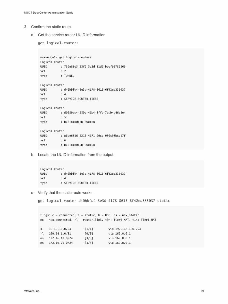
2 Confirm the static route.
a Get the service router UUID information.
get logical-routers
nsx-edge1> get logical-routers
Logical Router
UUID : 736a80e3-23f6-5a2d-81d6-bbefb2786666
vrf : 2
type : TUNNEL
Logical Router
UUID : d40bbfa4-3e3d-4178-8615-6f42ea335037
vrf : 4
type : SERVICE_ROUTER_TIER0
Logical Router
UUID : d0289ba4-250e-41b4-8ffc-7cab4a46c3e4
vrf : 5
type : DISTRIBUTED_ROUTER
Logical Router
UUID : a6ee6316-2212-4171-99cc-930c98bcad7f
vrf : 6
type : DISTRIBUTED_ROUTER
b Locate the UUID information from the output.
Logical Router
UUID : d40bbfa4-3e3d-4178-8615-6f42ea335037
vrf : 4
type : SERVICE_ROUTER_TIER0
c Verify that the static route works.
get logical-router d40bbfa4-3e3d-4178-8615-6f42ea335037 static
Flags: c - connected, s - static, b - BGP, ns - nsx_static
nc - nsx_connected, rl - router_link, t0n: Tier0-NAT, t1n: Tier1-NAT
s 10.10.10.0/24 [1/1] via 192.168.100.254
rl 100.64.1.0/31 [0/0] via 169.0.0.1
ns 172.16.10.0/24 [3/3] via 169.0.0.1
ns 172.16.20.0/24 [3/3] via 169.0.0.1
NSX-T Data Center Administration Guide
VMware, Inc. 69

3 From the external router, ping the internal VMs to confirm that they are reachable through the NSX-T Data Center overlay.
a Connect to the external router.
ping 172.16.10.10
PING 172.16.10.10 (172.16.10.10) 56(84) bytes of data.
64 bytes from 172.16.10.10: icmp_req=1 ttl=62 time=127 ms
64 bytes from 172.16.10.10: icmp_req=2 ttl=62 time=1.96 ms
^C
--- 172.16.10.10 ping statistics ---
2 packets transmitted, 2 received, 0% packet loss, time 1001ms
rtt min/avg/max/mdev = 1.966/64.793/127.620/62.827 ms
b Test the network connectivity.
traceroute 172.16.10.10
traceroute to 172.16.10.10 (172.16.10.10), 30 hops max, 60 byte packets
1 192.168.100.3 (192.168.100.3) 0.640 ms 0.575 ms 0.696 ms
2 100.64.1.1 (100.64.1.1) 0.656 ms 0.604 ms 0.578 ms
3 172.16.10.10 (172.16.10.10) 3.397 ms 3.703 ms 3.790 ms
4 From the VMs, ping the external IP address.
ping 10.10.10.10
PING 10.10.10.10 (10.10.10.10) 56(84) bytes of data.
64 bytes from 10.10.10.10: icmp_req=1 ttl=62 time=119 ms
64 bytes from 10.10.10.10: icmp_req=2 ttl=62 time=1.93 ms
^C
--- 10.10.10.10 ping statistics ---
2 packets transmitted, 2 received, 0% packet loss, time 1001ms
rtt min/avg/max/mdev = 1.936/60.865/119.795/58.930 ms
BGP Configuration OptionsTo take full advantage of the tier-0 logical router, the topology must be configured with redundancy and symmetry with BGP between the tier-0 routers and the external top-of-rack peers. This design helps to ensure connectivity in the event of link and node failures.
There are two modes of configuration: active-active and active-standby. The following diagram shows two options for symmetric configuration. There are two NSX Edge nodes shown in each topology. In the case of an active-active configuration, when you create tier-0 uplink ports, you can associate each uplink port with up to eight NSX Edge transport nodes. Each NSX Edge node can have two uplinks.
NSX-T Data Center Administration Guide
VMware, Inc. 70

Option 1
Edge Edge
Option 2
Spine
Leaf
Spine
Leaf
Edge Edge
Spine
Leaf
Spine
Leaf
For option 1, when the physical leaf-node routers are configured, they should have BGP neighborships with the NSX Edges. Route redistribution should include the same network prefixes with equal BGP metrics to all of the BGP neighbors. In the tier-0 logical router configuration, all leaf-node routers should be configured as BGP neighbors.
When you are configuring the tier-0 router's BGP neighbors, if you do not specify a local address (the source IP address), the BGP neighbor configuration is sent to all NSX Edge nodes associated with the tier-0 logical router uplinks. If you do configure a local address, the configuration goes to the NSX Edge node with the uplink owning that IP address.
In the case of option1, if the uplinks are on the same subnet on the NSX Edge nodes, it makes sense to omit the local address. If the uplinks on the NSX Edge nodes are in different subnets, the local address should be specified in the tier-0 router's BGP neighbor configuration to prevent the configuration from going to all associated NSX Edge nodes.
For option 2, ensure that the tier-0 logical router configuration includes the tier-0 services router's local IP address. The leaf-node routers are configured with only the NSX Edges that they are directly connected to as the BGP neighbor.
Configure BGP on a Tier-0 Logical RouterTo enable access between your VMs and the outside world, you can configure an external BGP (eBGP) connection between a tier-0 logical router and a router in your physical infrastructure.
When configuring BGP, you must configure a local Autonomous System (AS) number for the tier-0 logical router. For example, the following topology shows the local AS number is 64510. You must also configure the remote AS number of the physical router. In this example, the remote AS number is 64511. The remote neighbor IP address is 192.168.100.254. The neighbor must be in the same IP subnet as the uplink on the tier-0 logical router. BGP multihop is supported.
NSX-T Data Center Administration Guide
VMware, Inc. 71

For test purposes, the 10.10.10.10/32 address is configured on the external router loopback interface.
Note Router ID used for forming BGP sessions on an edge node is autoselected from the IP addresses configured on the uplinks of a tier-0 logical router. BGP sessions on an edge node can flap when router ID changes. This can happen when the IP address auto-selected for router ID is deleted or the logical router port on which this IP is assigned is deleted.
Figure 5-3. BGP Connection Topology
VM VM
100.64.10.0
172.16.20.10 172.16.10.10
appVM
webVM
tier-0
PhysicalArchitecture
tier-1
Host
192.168.100.3
AS 64510
100.64.10.1
AS 64511192.168.100.254
lo0:10.10.10.10
Prerequisites
n Verify that the tier-1 router is configured to advertise connected routes. See Configure Route Advertisement on a Tier-1 Logical Router. This is not strictly a prerequisite for BGP configuration, but if you have a two-tier topology and you plan to redistribute your tier-1 networks into BGP, this step is required.
n Verify that a tier-0 router is configured. See Create a Tier-0 Logical Router.
n Make sure the tier-0 logical router has learned routes from the tier-1 logical router. See Verify that a Tier-0 Router Has Learned Routes from a Tier-1 Router.
Procedure
1 From your browser, log in with admin privileges to an NSX Manager at https://nsx-manager-ip-address.
2 Select Networking > Routing from the navigation panel.
3 Select the tier-0 logical router.
NSX-T Data Center Administration Guide
VMware, Inc. 72

4 Click the Routing tab and select BGP from the drop-down menu.
5 Click Edit.
a Configure the local AS number.
For example, 64510.
b Click the Status toggle button to enable BGP.
The Status button must be appear as Enabled.
c (Optional) Click the ECMP toggle button to enable ECMP.
d (Optional) Click the Graceful Restart toggle button to enable graceful restart.
e (Optional) Configure route aggregation, enable graceful restart, and enable ECMP.
Graceful restart is only supported if the NSX Edge cluster associated with the tier-0 router has only one edge node.
f Click Save.
6 Click Add to add a BGP neighbor.
7 Enter the neighbor IP address.
For example, 192.168.100.254.
8 (Optional) Specify the maximum hop limit.
The default is 1.
9 Enter the remote AS number.
For example, 64511.
10 (Optional) Configure the timers (keep alive time and hold down time) and a password.
11 (Optional) Click the Local Address tab to select a local address.
a (Optional) Uncheck All Uplinks to see loopback ports as well as uplink ports.
12 (Optional) Click the Address Families tab to add an address family.
13 (Optional) Click the BFD Configuration tab to enable BFD.
14 Click Save.
What to do next
Test whether BGP is working properly. See Verify BGP Connections from a Tier-0 Service Router .
Verify BGP Connections from a Tier-0 Service RouterUse the CLI to verify from the tier-0 service router that a BGP connection to a neighbor is established.
Prerequisites
Verify that BGP is configured. See Configure BGP on a Tier-0 Logical Router.
NSX-T Data Center Administration Guide
VMware, Inc. 73

Procedure
1 Log in to the NSX Manager CLI.
2 On the NSX Edge, run the get logical-routers command to find the VRF number of the tier-0 service router.
nsx-edge-1> get logical-routers
Logical Router
UUID : 736a80e3-23f6-5a2d-81d6-bbefb2786666
vrf : 0
type : TUNNEL
Logical Router
UUID : 421a2d0d-f423-46f1-93a1-2f9e366176c8
vrf : 5
type : SERVICE_ROUTER_TIER0
Logical Router
UUID : f3ce9d7d-7123-47d6-aba6-45cf1388ca7b
vrf : 6
type : DISTRIBUTED_ROUTER
Logical Router
UUID : c8e64eff-02b2-4462-94ff-89f3788f1a61
vrf : 7
type : SERVICE_ROUTER_TIER1
Logical Router
UUID : fb6c3f1f-599f-4421-af8a-99692dff3dd4
vrf : 8
type : DISTRIBUTED_ROUTER
3 Run the vrf <number> command to enter the tier-0 service router context.
nsx-edge-1> vrf 5
nsx-edge1(tier0_sr)>
4 Verify that the BGP state is Established, up.
get bgp neighbor
BGP neighbor: 192.168.100.254 Remote AS: 64511
BGP state: Established, up
Hold Time: 180s Keepalive Interval: 60s
Capabilities:
Route Refresh: advertised and received
Address Family: IPv4 Unicast:advertised and received
Graceful Restart: none
Restart Remaining Time: 0
Messages: 28 received, 31 sent
NSX-T Data Center Administration Guide
VMware, Inc. 74

Minimum time between advertisements: 30s (default)
For Address Family IPv4 Unicast:advertised and received
Route Refresh: 0 received, 0 sent
Prefixes: 2 received, 2 sent, 2 advertised
1 Connections established, 2 dropped
Local host: 192.168.100.3, Local port: 179
Remote host: 192.168.100.254, Remote port: 33044
What to do next
Check the BGP connection from the external router. See Verify North-South Connectivity and Route Redistribution.
Configure BFD on a Tier-0 Logical RouterBFD (Bidirectional Forwarding Detection) is a protocol that can detect forwarding path failures.
Note In this release, BFD over Virtual Tunnel Interface (VTI) ports is not supported.
Procedure
1 From your browser, log in with admin privileges to an NSX Manager at https://nsx-manager-ip-address.
2 Select Networking > Routing from the navigation panel.
3 Select the tier-0 logical router.
4 Click the Routing tab and select BFD from the drop-down menu.
5 Click Edit to configure BFD.
6 Click the Status toggle button to enable BFD.
You can optionally change the global BFD properties Receive interval, Transmit interval, and Declare dead interval.
7 (Optional) Click Add under BFD Peers for Static Route Next Hops to add a BFD peer.
Specify the peer IP address and set the admin status to Enabled. Optionally, you can override the global BFD properties Receive interval, Transmit interval, and Declare dead interval.
Enable Route Redistribution on the Tier-0 Logical RouterWhen you enable route redistribution, the tier-0 logical router starts sharing specified routes with its northbound router.
Prerequisites
n Verify that the tier-0 and tier-1 logical routers are connected so that you can advertise the tier-1 logical router networks to redistribute them on the tier-0 logical router. See Attach Tier-0 and Tier-1.
NSX-T Data Center Administration Guide
VMware, Inc. 75

n If you want to filter specific IP addresses from route redistribution, verify that route maps are configured. See Create a Route Map.
Procedure
1 From your browser, log in with admin privileges to an NSX Manager at https://nsx-manager-ip-address.
2 Select Networking > Routing from the navigation panel.
3 Select the tier-0 logical router.
4 Click the Routing tab and select Route Redistribution from the drop-down menu.
5 Click Add to complete the route redistribution criteria.
Option Description
Name and Description Assign a name to the route redistribution. You can optionally provide a description.
An example name, advertise-to-bgp-neighbor.
Sources Select the source route check boxes you want to redistribute.
Static - Tier-0 static routes.
NSX Connected - Tier-1 connected routes.
NSX Static - Tier-1 static routes. These static routes are created automatically.
Tier-0 NAT - Routes generated if NAT is configured on the tier-0 logical router.
Tier-1 NAT - Routes generated if NAT is configured on the tier-1 logical router.
Route Map (Optional) Assign a route map to filter a sequence of IP addresses from route redistribution.
6 Click Save.
7 Click the Status toggle button to enable route redistribution.
The Status button appears as Enabled.
Verify North-South Connectivity and Route RedistributionUse the CLI to verify that the BGP routes are learned. You can also check from the external router that the NSX-T Data Center-connected VMs are reachable.
Prerequisites
n Verify that BGP is configured. See Configure BGP on a Tier-0 Logical Router.
n Verify that NSX-T Data Center static routes are set to be redistributed. See Enable Route Redistribution on the Tier-0 Logical Router.
Procedure
1 Log in to the NSX Manager CLI.
NSX-T Data Center Administration Guide
VMware, Inc. 76

2 View the routes learned from the external BGP neighbor.
nsx-edge1(tier0_sr)> get route bgp
Flags: c - connected, s - static, b - BGP, ns - nsx_static
nc - nsx_connected, rl - router_link, t0n: Tier0-NAT, t1n: Tier1-NAT
b 10.10.10.0/24 [20/0] via 192.168.100.254
3 From the external router, check that BGP routes are learned and that the VMs are reachable through the NSX-T Data Center overlay.
a List the BGP routes.
user@router# run show ip route bgp
Codes: K - kernel route, C - connected, S - static, R - RIP, O - OSPF,
I - ISIS, B - BGP, > - selected route, * - FIB route
B>* 172.16.10.0/24 [20/0] via 192.168.100.2, eth2, 00:00:48
B>* 172.16.20.0/24 [20/0] via 192.168.100.2, eth2, 00:00:48
B>* 172.16.30.0/24 [20/0] via 192.168.100.2, eth2, 00:00:48
b From the external router, ping the NSX-T Data Center-connected VMs.
ping 172.16.10.10
PING 172.16.10.10 (172.16.10.10) 56(84) bytes of data.
64 bytes from 172.16.10.10: icmp_req=1 ttl=62 time=127 ms
64 bytes from 172.16.10.10: icmp_req=2 ttl=62 time=1.96 ms
^C
--- 172.16.10.10 ping statistics ---
2 packets transmitted, 2 received, 0% packet loss, time 1001ms
rtt min/avg/max/mdev = 1.966/64.793/127.620/62.827 ms
c Check the path through the NSX-T Data Center overlay.
traceroute 172.16.10.10
traceroute to 172.16.10.10 (172.16.10.10), 30 hops max, 60 byte packets
1 192.168.100.3 (192.168.100.3) 0.640 ms 0.575 ms 0.696 ms
2 100.91.176.1 (100.91.176.1) 0.656 ms 0.604 ms 0.578 ms
3 172.16.10.10 (172.16.10.10) 3.397 ms 3.703 ms 3.790 ms
4 From the internal VMs, ping the external IP address.
ping 10.10.10.10
PING 10.10.10.10 (10.10.10.10) 56(84) bytes of data.
NSX-T Data Center Administration Guide
VMware, Inc. 77

64 bytes from 10.10.10.10: icmp_req=1 ttl=62 time=119 ms
64 bytes from 10.10.10.10: icmp_req=2 ttl=62 time=1.93 ms
^C
--- 10.10.10.10 ping statistics ---
2 packets transmitted, 2 received, 0% packet loss, time 1001ms
rtt min/avg/max/mdev = 1.936/60.865/119.795/58.930 ms
What to do next
Configure additional routing functionality, such as ECMP.
Understanding ECMP RoutingEqual cost multi-path (ECMP) routing protocol increases the north and south communication bandwidth by adding an uplink to the tier-0 logical router and configure it for each Edge node in an NSX Edge cluster. The ECMP routing paths are used to load balance traffic and provide fault tolerance for failed paths.
ECMP paths are automatically created from the VMs attached to logical switches to the Edge nodes on which the tier-0 logical router is instantiated. A maximum of eight ECMP paths are supported.
Figure 5-4. ECMP Routing Topology
PhysicalArchitecture
Tier-0
192.168.100.3
Edge Node 1
Tier-0
Edge Node 2
192.168.200.3
Edge Cluster
192.168.100.1 192.168.200.1
VLANSwitch
Uplink 2Uplink 1
NSX-T Data Center Administration Guide
VMware, Inc. 78

For example, the topology shows two tier-0 logical routers in an NSX Edge cluster. Each tier-0 logical router is in an edge node and these nodes are part of the cluster. The uplink ports 192.168.100.3 and 198.168.200.3 define how the transport node connects to the logical switch to gain access to the physical network. When the ECMP routing paths are enabled these paths connect the VMs attached to logical switches and the two Edge nodes in the NSX Edge cluster. The multiple ECMP routing paths increase the network throughput and resiliency.
Add an Uplink Port for the Second Edge NodeBefore you enable ECMP, you must configure an uplink to connect the tier-0 logical router to the VLAN logical switch.
Prerequisites
n Verify that a transport zone and two transport nodes are configured. See the NSX-T Data Center Installation Guide.
n Verify that two Edge nodes and an Edge cluster are configured. See the NSX-T Data Center Installation Guide.
n Verify that a VLAN logical switch for uplink is available. See Create a VLAN Logical Switch for the NSX Edge Uplink.
n Verify that a tier-0 logical router is configured. See Create a Tier-0 Logical Router.
Procedure
1 From your browser, log in with admin privileges to an NSX Manager at https://nsx-manager-ip-address.
2 Select Networking > Routing from the navigation panel.
3 Select the tier-0 logical router.
4 Click the Configuration tab to add a router port.
5 Click Add.
6 Complete the router port details.
Option Description
Name Assign a name for the router port.
Description Provide additional description that shows that the port is for ECMP configuration.
Type Accept the default type Uplink.
Transport Node Assign the host transport node from the drop-down menu.
Logical Switch Assign the VLAN logical switch from the drop-down menu.
NSX-T Data Center Administration Guide
VMware, Inc. 79

Option Description
Logical Switch Port Assign a new switch port name.
You can also use an existing switch port.
IP Address/Mask Enter an IP address that is in the same subnet as the connected port on the ToR switch.
7 Click Save.
A new uplink port is added to the tier-0 router and the VLAN logical switch. The tier-0 logical router is configured on both of the edge nodes.
What to do next
Create a BGP connection for the second neighbor and enable the ECMP routing. See Add a Second BGP Neighbor and Enable ECMP Routing.
Add a Second BGP Neighbor and Enable ECMP RoutingBefore you enable ECMP routing, you must add a BGP neighbor and configure it with the newly added uplink information.
Prerequisites
Verify that the second edge node has an uplink port configured. See Add an Uplink Port for the Second Edge Node .
Procedure
1 From your browser, log in with admin privileges to an NSX Manager at https://nsx-manager-ip-address.
2 Select Networking > Routing from the navigation panel.
3 Select the tier-0 logical router.
4 Click the Routing tab and select BGP from the drop-down menu.
5 Click Add under the Neighbors section to add a BGP neighbor.
6 Enter the neighbor IP address.
For example, 192.168.200.254.
7 (Optional) Specify the maximum hop limit.
The default is 1.
8 Enter the remote AS number.
For example, 64511.
9 (Optional) Click the Local Address tab to select a local address.
a (Optional) Uncheck All Uplinks to see loopback ports as well as uplink ports.
10 (Optional) Click the Address Families tab to add an address family.
NSX-T Data Center Administration Guide
VMware, Inc. 80

11 (Optional) Click the BFD Configuration tab to enable BFD.
12 Click Save.
The newly added BGP neighbor appears.
13 Click Edit next to the BGP Configuration section.
14 Click the ECMP toggle button to enable ECMP.
The Status button must be appear as Enabled.
15 Click Save.
Multiple ECMP routing paths connect the VMs attached to logical switches and the two Edge nodes in the Edge cluster.
What to do next
Test whether the ECMP routing connections are working properly. See Verify ECMP Routing Connectivity.
Verify ECMP Routing ConnectivityUse CLI to verify that the ECMP routing connection to neighbor is established.
Prerequisites
Verify that ECMP routing is configured. See Add an Uplink Port for the Second Edge Node and Add a Second BGP Neighbor and Enable ECMP Routing.
Procedure
1 Log in to the NSX Manager CLI.
2 Get the distributed router UUID information.
get logical-routers
Logical Router
UUID : 736a80e3-23f6-5a2d-81d6-bbefb2786666
vrf : 2
type : TUNNEL
Logical Router
UUID : d40bbfa4-3e3d-4178-8615-6f42ea335037
vrf : 4
type : SERVICE_ROUTER_TIER0
Logical Router
UUID : d0289ba4-250e-41b4-8ffc-7cab4a46c3e4
vrf : 5
type : DISTRIBUTED_ROUTER
NSX-T Data Center Administration Guide
VMware, Inc. 81

Logical Router
UUID : a6ee6316-2212-4171-99cc-930c98bcad7f
vrf : 6
type : DISTRIBUTED_ROUTER
3 Locate the UUID information from the output.
Logical Router
UUID : d0289ba4-250e-41b4-8ffc-7cab4a46c3e4
vrf : 5
type : DISTRIBUTED_ROUTER
4 Type the VRF for the tier-0 distributed router.
vrf 5
5 Verify that the tier-0 distributed router is connected to the Edge nodes.
get forwarding
For example, edge-node-1 and edge-node-2.
6 Enter exit to leave the vrf context.
7 Open the active controller for the tier-0 logical router.
8 Verify that the tier-0 distributed router on the controller node is connected.
get logical-router <UUID> route
The route type for the UUID should appear as NSX_CONNECTED.
9 Start a SSH session on the two Edge nodes.
10 Start a session to capture packets.
set capture session 0 interface fp-eth1 dir tx
set capture session 0 expression src net <IP_Address>
11 Navigate to the Control Center and double click the httpdata11.bat and httpdata12.bat scripts.
A large number of HTTP requests to both Web VMs is sent and you see traffic hashed to both paths using the Edge nodes, which shows that ECMP is working.
12 Stop the capture session.
del capture session 0
13 Remove the bat scripts.
Create an IP Prefix ListAn IP prefix list contains single or multiple IP addresses that are assigned access permissions for route advertisement. The IP addresses in this list are processed sequentially. IP prefix lists are referenced through BGP neighbor filters or route maps with in or out direction.
NSX-T Data Center Administration Guide
VMware, Inc. 82
For example, you can add the IP address 192.168.100.3/27 to the IP prefix list and deny the route from being redistributed to the northbound router. You can also append an IP address with less-than-or-equal-to (le) and greater-than-or-equal-to (ge) modifiers to grant or limit route redistribution. For example, 192.168.100.3/27 ge 24 le 30 modifiers match subnet masks greater than or equal to 24-bits and less than or equal to 30-bits in length.
Note The default action for a route is Deny. When you create a prefix list to deny or permit specific routes, be sure to create an IP prefix with no specific network address (select Any from the dropdown list) and the Permit action if you want to permit all other routes.
Prerequisites
Verify that you have a tier-0 logical router configured. See Create a Tier-0 Logical Router.
Procedure
1 From your browser, log in with admin privileges to an NSX Manager at https://nsx-manager-ip-address.
2 Select Networking > Routing from the navigation panel.
3 Select the tier-0 logical router.
4 Click the Routing tab and select IP Prefix Lists from the drop-down menu.
5 Click Add.
6 Enter a name for the IP prefix list.
7 Click Add to specify a prefix.
a Enter an IP address in CIDR format.
For example, 192.168.100.3/27.
b Select Deny or Permit from the drop-down menu.
c (Optional) Set a range of IP address numbers in the le or ge modifiers.
For example, set le to 30 and ge to 24.
8 Repeat the previous step to specify additional prefixes.
9 Click Add at the bottom of the window.
Create a Community ListYou can create BGP community lists so that you can configure route maps based on community lists.
Prerequisites
Verify that you have a tier-0 logical router configured. See Create a Tier-0 Logical Router.
NSX-T Data Center Administration Guide
VMware, Inc. 83

Procedure
1 From your browser, log in with admin privileges to an NSX Manager at https://nsx-manager-ip-address.
2 Select Networking > Routing from the navigation panel.
3 Select the tier-0 logical router.
4 Click the Routing tab and select Community Lists from the drop-down menu.
5 Click Add.
6 Enter a name for the community list.
7 Specify a community using the aa:nn format, for example, 300:500, and press Enter. Repeat to add additional communities.
In addition, you can click the dropdown arrow and select one or more of the following:
n NO_EXPORT_SUBCONFED - Do not advertise to EBGP peers.
n NO_ADVERTISE - Do not advertise to any peer.
n NO_EXPORT - Do not advertise outside BGP confederation
8 Click Add.
Create a Route MapA route map consists of a sequence of IP prefix lists, BGP path attributes, and an associated action. The router scans the sequence for an IP address match. If there is a match, the router performs the action and scans no further.
Route maps can be referenced at the BGP neighbor level and route redistribution. When IP prefix lists are referenced in route maps and the route map action of permitting or denying is applied, the action specified in the route map sequence overrides the specification within the IP prefix list.
Prerequisites
Verify that an IP prefix list is configured. See Create an IP Prefix List.
Procedure
1 From your browser, log in with admin privileges to an NSX Manager at https://nsx-manager-ip-address.
2 Select Networking > Routing from the navigation panel.
3 Select the tier-0 logical router.
4 Select Routing > Route Maps.
5 Click Add.
6 Enter a name and an optional description for the route map.
NSX-T Data Center Administration Guide
VMware, Inc. 84

7 Click Add to add an entry in the route map.
8 Edit the column Match IP Prefix List/Community List to select either IP prefix lists, or community lists, but not both.
9 (Optional) Set BGP attributes.
BGP Attribute Description
AS-path Prepend Prepend a path with one or more AS (autonomous system) numbers to make the path longer and therefore less preferred.
MED Multi-Exit Discriminator indicates to an external peer a preferred path to an AS.
Weight Set a weight to influence path selection. The range is 0 - 65535.
Community Specify a community using the aa:nn format, for example, 300:500. Or use the drop-down menu to select one of the following:
n NO_EXPORT_SUBCONFED - Do not advertise to EBGP peers.
n NO_ADVERTISE - Do not advertise to any peer.
n NO_EXPORT - Do not advertise outside BGP confederation
10 In the Action column, select Permit or Deny.
You can permit or deny IP addresses in the IP prefix lists from advertising their addresses.
11 Click Save.
Configure Forwarding Up TimerYou can configure forwarding up timer for a tier-0 logical router.
Forwarding up timer defines the time in seconds that the router must wait before sending the up notification after the first BGP session is established. This timer (previously known as forwarding delay) minimizes downtime in case of fail-overs for active-active or active-standby configurations of logical routers on NSX Edge that use dynamic routing (BGP). It should be set to the number of seconds an external router (TOR) takes to advertise all the routes to this router after the first BGP/BFD session. The timer value should be directly proportional to the number of northbound dynamic routes that the router must learn. This timer should be set to 0 on single edge node setups.
Procedure
1 From your browser, log in with admin privileges to an NSX Manager at https://nsx-manager-ip-address.
2 Select Networking > Routing from the navigation panel.
3 Select the tier-0 logical router.
4 Select Routing > Global Configuration
5 Click Edit.
6 Enter a value for the forwarding up timer.
7 Click Save.
NSX-T Data Center Administration Guide
VMware, Inc. 85

Network Address Translation 6Network address translation (NAT) in NSX-T Data Center can be configured on tier-0 and tier-1 logical routers.
For example, the following diagram shows two tier-1 logical routers with NAT configured on Tenant2NAT. The web VM is simply configured to use 172.16.10.10 as its IP address and 172.16.10.1 as its default gateway.
NAT is enforced at the uplink of the Tenant2NAT logical router on its connection to the tier-0 logical router.
To enable NAT configuration, Tenant2NAT must have a service component on an NSX Edge cluster. Thus, Tenant2NAT is shown inside the NSX Edge. For comparison, Tenant1 can be outside of the NSX Edge because it is not using any Edge services.
VMware, Inc. 86

Figure 6-1. NAT Topology
VM VM
172.16.20.10Inside: 172.16.10.10Outside: 80.80.80.1
appVM
webVM
Tenant2NATtier-1
Host
172.16.10.1
weblogical switch
tier-0
NSX Edge
applogical switch
Tenant1tier-1
172.16.20.1
PhysicalArchitecture
192.168.100.3
VLAN-basedlogical switch
192.168.100.1
This chapter includes the following topics:
n Tier-1 NAT
n Tier-0 NAT
n Reflexive NAT
Tier-1 NATTier-1 logical routers support source NAT and destination NAT.
Configure Source NAT on a Tier-1 RouterSource NAT (SNAT) changes the source address in the IP header of a packet. It can also change the source port in the TCP/UDP headers. The typical usage is to change a private (rfc1918) address/port into a public address/port for packets leaving your network.
You can create a rule to either enable or disable source NAT.
NSX-T Data Center Administration Guide
VMware, Inc. 87

In this example, as packets are received from the web VM, the Tenant2NAT tier-1 router changes the source IP address of the packets from 172.16.10.10 to 80.80.80.1. Having a public source IP address enables destinations outside of the private network to route back to the original source.
Prerequisites
n The tier-0 router must have an uplink connected to a VLAN-based logical switch. See Connect a Tier-0 Logical Router to a VLAN Logical Switch for the NSX Edge Uplink.
n The tier-0 router must have routing (static or BGP) and route redistribution configured on its uplink to the physical architecture. See Configure a Static Route, Configure BGP on a Tier-0 Logical Router, and Enable Route Redistribution on the Tier-0 Logical Router.
n The tier-1 routers must each have an uplink to a tier-0 router configured. Tenant2NAT must be backed by an NSX Edge cluster. See Attach Tier-0 and Tier-1.
n The tier-1 routers must have downlink ports and route advertisement configured. See Add a Downlink Port on a Tier-1 Logical Router and Configure Route Advertisement on a Tier-1 Logical Router.
n The VMs must be attached to the correct logical switches.
Procedure
1 From your browser, log in with admin privileges to an NSX Manager at https://nsx-manager-ip-address.
2 Select Networking > Routing from the navigation panel.
3 Click a tier-1 logical router on which you want to configure NAT.
4 Select Services > NAT.
5 Click ADD.
6 Specify a priority value.
A lower value means a higher precedence for this rule.
7 For Action, select SNAT to enable source NAT, or NO_SNAT to disable source NAT.
8 Select the protocol type.
By default, Any Protocol is selected.
9 (Optional) For Source IP, specify an IP address or an IP address range in CIDR format.
If you leave this field blank, all sources on router's downlink ports are translated. In this example, the source IP address is 172.16.10.10.
10 (Optional) For Destination IP, specify an IP address or an IP address range in CIDR format.
If you leave this field blank, the NAT applies to all destinations outside of the local subnet.
11 If Action is SNAT, for Translated IP, specify an IP address or an IP address range in CIDR format.
In this example, the translated IP address is 80.80.80.1.
12 (Optional) For Applied To, select a router port.
NSX-T Data Center Administration Guide
VMware, Inc. 88

13 (Optional) Set the status of the rule.
The rule is enabled by default.
14 (Optional) Change the logging status.
Logging is disabled by default.
15 (Optional) Change the firewall bypass setting.
The setting is enabled by default.
The new rule is listed under NAT. For example:
What to do next
Configure the tier-1 router to advertise NAT routes.
To advertise the NAT routes upstream from the tier-0 router to the physical architecture, configure the tier-0 router to advertise tier-1 NAT routes.
Configure Destination NAT on a Tier-1 RouterDestination NAT changes the destination address in IP header of a packet. It can also change the destination port in the TCP/UDP headers. The typical usage of this is to redirect incoming packets with a destination of a public address/port to a private IP address/port inside your network.
You can create a rule to either enable or disable destination NAT.
In this example, as packets are received from the app VM, the Tenant2NAT tier-1 router changes the destination IP address of the packets from 172.16.10.10 to 80.80.80.1. Having a public destination IP address enables a destination inside a private network to be contacted from outside of the private network.
Prerequisites
n The tier-0 router must have an uplink connected to a VLAN-based logical switch. See Connect a Tier-0 Logical Router to a VLAN Logical Switch for the NSX Edge Uplink.
NSX-T Data Center Administration Guide
VMware, Inc. 89

n The tier-0 router must have routing (static or BGP) and route redistribution configured on its uplink to the physical architecture. See Configure a Static Route, Configure BGP on a Tier-0 Logical Router, and Enable Route Redistribution on the Tier-0 Logical Router.
n The tier-1 routers must each have an uplink to a tier-0 router configured. Tenant2NAT must be backed by an NSX Edge cluster. See Attach Tier-0 and Tier-1.
n The tier-1 routers must have downlink ports and route advertisement configured. See Add a Downlink Port on a Tier-1 Logical Router and Configure Route Advertisement on a Tier-1 Logical Router.
n The VMs must be attached to the correct logical switches.
Procedure
1 From your browser, log in with admin privileges to an NSX Manager at https://nsx-manager-ip-address.
2 Select Networking > Routing from the navigation panel.
3 Click a tier-1 logical router on which you want to configure NAT.
4 Select Services > NAT.
5 Click ADD.
6 Specify a priority value.
A lower value means a higher precedence for this rule.
7 For Action, select DNAT to enable destination NAT, or NO_DNAT to disable destination NAT.
8 Select the protocol type.
By default, Any Protocol is selected.
9 (Optional) For Source IP, specify an IP address or an IP address range in CIDR format.
If you leave Source IP blank, the NAT applies to all sources outside of the local subnet.
10 For Destination IP, specify an IP address or an IP address range in CIDR format.
In this example, the destination IP address is 80.80.80.1.
11 If Action is DNAT, for Translated IP, specify an IP address or an IP address range in CIDR format.
In this example, the inside/translated IP address is 172.16.10.10.
12 (Optional) If Action is DNAT, for Translated Ports, specify the translated ports.
13 (Optional) For Applied To, select a router port.
14 (Optional) Set the status of the rule.
The rule is enabled by default.
15 (Optional) Change the logging status.
Logging is disabled by default.
NSX-T Data Center Administration Guide
VMware, Inc. 90

16 (Optional) Change the firewall bypass setting.
The setting is enabled by default.
The new rule is listed under NAT. For example:
What to do next
Configure the tier-1 router to advertise NAT routes.
To advertise the NAT routes upstream from the tier-0 router to the physical architecture, configure the tier-0 router to advertise tier-1 NAT routes.
Advertise Tier-1 NAT Routes to the Upstream Tier-0 RouterAdvertising tier-1 NAT routes enables the upstream tier-0 router to learn about these routes.
Procedure
1 From your browser, log in with admin privileges to an NSX Manager at https://nsx-manager-ip-address.
2 Select Networking > Routing from the navigation panel.
3 Click a tier-1 logical router on which you have configured NAT.
4 From the tier-1 router, select Routing > Route Advertisement.
5 Edit the route advertisement rules to enable NAT route advertisement.
NSX-T Data Center Administration Guide
VMware, Inc. 91

What to do next
Advertise tier-1 NAT routes from the tier-0 router to the upstream physical architecture.
Advertise Tier-1 NAT Routes to the Physical ArchitectureAdvertising tier-1 NAT routes from the tier-0 router enables the upstream physical architecture to learn about these routes.
Procedure
1 From your browser, log in with admin privileges to an NSX Manager at https://nsx-manager-ip-address.
2 Select Routing.
3 Click a tier-0 logical router that is connected to a tier-1 router on which you have configured NAT.
4 From the tier-0 router, select Routing > Route Redistribution.
5 Edit the route advertisement rules to enable tier-1 NAT route advertisement.
NSX-T Data Center Administration Guide
VMware, Inc. 92

What to do next
Verify NAT is working as expected.
Verify Tier-1 NATVerify that SNAT and DNAT rules are working correctly.
Procedure
1 Log in the NSX Edge.
2 Run get logical-routers to determine the VRF number for the tier-0 services router.
3 Enter the tier-0 services router context by running the vrf <number> command.
4 Run the get route command and make sure that the tier-1 NAT address appears.
nsx-edge(tier0_sr)> get route
Flags: c - connected, s - static, b - BGP, ns - nsx_static
nc - nsx_connected, rl - router_link, t0n: Tier0-NAT, t1n: Tier1-NAT
NSX-T Data Center Administration Guide
VMware, Inc. 93

Total number of routes: 8
t1n 80.80.80.1/32 [3/3] via 169.0.0.1
...
5 If your Web VM is set up to serve Web pages, make sure you can open a Web page at http://80.80.80.1.
6 Make sure that the tier-0 router's upstream neighbor in the physical architecture can ping 80.80.80.1.
7 While the ping is still running, check the stats column for the DNAT rule.
There should be one active session.
Tier-0 NATTier-0 logical routers support source NAT, destination NAT, and reflexive NAT.
Configure Source and Destination NAT on a Tier-0 RouterYou can configure source and destination NAT on a tier-0 router that is running in active-standby mode.
You can also configure No NAT, No SNAT, or No DNAT to disable NAT for an IP address or a range of addresses. If multiple NAT rules apply to an address, the rule with the highest priority is applied.
Procedure
1 From your browser, log in with admin privileges to an NSX Manager at https://nsx-manager-ip-address.
2 Select Networking > Routing from the navigation panel.
3 Click a tier-0 logical router.
4 Select Services > NAT.
5 Click ADD to add a NAT rule.
6 Specify a priority value.
A lower value means a higher priority.
7 For Action, select SNAT, DNAT, No NAT, NO_SNAT, or NO_DNAT.
8 Select the protocol type.
By default, Any Protocol is selected.
9 (Required) For Source IP, specify an IP address or an IP address range in CIDR format.
If you leave this field blank, this NAT rule applies to all sources outside of the local subnet.
10 For Destination IP, specify an IP address or an IP address range in CIDR format.
11 For Translated IP, specify an IP address or an IP address range in CIDR format.
NSX-T Data Center Administration Guide
VMware, Inc. 94

12 (Optional) If Action is DNAT, for Translated Ports, specify the translated ports.
13 (Optional) For Applied To, select a router port.
14 (Optional) Set the status of the rule.
The rule is enabled by default.
15 (Optional) Change the logging status.
Logging is disabled by default.
16 (Optional) Change the firewall bypass setting.
The setting is enabled by default.
Reflexive NATWhen a tier-0 or tier-1 logical router is running in active-active mode, you cannot configure stateful NAT where asymmetrical paths might cause issues. For active-active routers, you can use reflexive NAT (sometimes called stateless NAT).
In this example, as packets are received from the web VM, the Tenant2NAT tier-1 router changes the source IP address of the packets from 172.16.10.10 to 80.80.80.1. Having a public source IP address enables destinations outside of the private network to route back to the original source.
NSX-T Data Center Administration Guide
VMware, Inc. 95

VM VM
172.16.20.10Inside: 172.16.10.10Outside: 80.80.80.1
appVM
webVM
Tenant2NATtier-1
Host
172.16.10.1
weblogical switch
tier-0
NSX Edge
applogical switch
Tenant1tier-1
172.16.20.1
PhysicalArchitecture
192.168.100.3
VLAN-basedlogical switch
192.168.100.1
When there are two active-active tier-0 routers involved, as shown here, reflexive NAT must be configured.
NSX-T Data Center Administration Guide
VMware, Inc. 96

PhysicalArchitecture
Tier-0
192.168.100.3
Edge Node 1
Tier-0
Edge Node 2
192.168.200.3
Edge Cluster
192.168.100.1 192.168.200.1
VLANSwitch
Uplink 2Uplink 1
Configure Reflexive NAT on a Tier-0 or Tier-1 Logical RouterWhen a tier-0 or tier-1 logical router is running in active-active mode, you cannot configure stateful NAT where asymmetrical paths might cause issues. For active-active routers, you can use reflexive NAT, which is sometimes called stateless NAT.
For reflexive NAT, you can configure a single source address to be translated, or a range of addresses. If you configure a range of source addresses, you must also configure a range of translated addresses. The size of the two ranges must be the same. The address translation will be deterministic, meaning that the first address in the source address range will be translated to the first address in the translated address range, the second address in the source range will be translated to the second address in the translated range, and so on.
Procedure
1 From your browser, log in with admin privileges to an NSX Manager at https://nsx-manager-ip-address.
2 Select Networking > Routing from the navigation panel.
3 Click a tier-0 or tier-1 logical router on which you want to configure reflexive NAT.
4 Select Services > NAT.
5 Click ADD.
NSX-T Data Center Administration Guide
VMware, Inc. 97

6 Specify a priority value.
A lower value means a higher precedence for this rule.
7 For Action, select Reflexive.
8 For Source IP, specify an IP address or an IP address range in CIDR format.
9 For Translated IP, specify an IP address or an IP address range in CIDR format.
10 (Optional) Set the status of the rule.
The rule is enabled by default.
11 (Optional) Change the logging status.
Logging is disabled by default.
12 (Optional) Change the firewall bypass setting.
The setting is enabled by default.
The new rule is listed under NAT. For example:
NSX-T Data Center Administration Guide
VMware, Inc. 98

Firewall Sections and Firewall Rules 7Firewall sections are used to group a set of firewall rules.
A firewall section is made up from one or more individual firewall rules. Each individual firewall rule contains instructions that determine whether a packet should be allowed or blocked; which protocols it is allowed to use; which ports it is allowed to use and so forth. Sections are used for multi-tenancy , such as specific rules for sales and engineering departments in separate sections.
A section can be defined as enforcing stateful or stateless rules. Stateless rules are treated as traditional stateless ACLs. Reflexive ACLs are not supported for stateless sections. A mix of stateless and stateful rules on a single logical switch port is not recommended and may cause undefined behavior.
Rules can be moved up and down within a section. For any traffic attempting to pass through the firewall, the packet information is subjected to the rules in the order shown in the section, beginning at the top and proceeding to the default rule at the bottom. The first rule that matches the packet has its configured action applied, and any processing specified in the rule's configured options is performed and all subsequent rules are ignored (even if a later rule is a better match). Thus, you should place specific rules above more general rules to ensure those rules are not ignored. The default rule, located at the bottom of the rule table, is a "catchall" rule; packets not matching any other rules will be enforced by the default rule.
Note A logical switch has a property called N-VDS mode. This property comes from the transport zone that the switch belongs to. If the N-VDS mode is ENS (also known as Enhanced Datapath), then you cannot create a firewall rule or section with the switch or its ports in the Source, Destination, or Applied To fields.
This chapter includes the following topics:
n Add a Firewall Rule Section
n Delete a Firewall Rule Section
n Enable and Disable Section Rules
n Enable and Disable Section Logs
n About Firewall Rules
n Add a Firewall Rule
n Delete a Firewall Rule
VMware, Inc. 99

n Edit the Default Distributed Firewall Rule
n Change the Order of a Firewall Rule
n Filter Firewall Rules
n Configure Firewall for a Logical Switch Bridge Port
n Configure a Firewall Exclusion List
n Enable and Disable Firewall
n Add or Delete a Firewall Rule to a Logical Router
Add a Firewall Rule Section
A firewall rule section is edited and saved independently and is used to apply separate firewall configuration to tenants.
Procedure
1 Select Security > Distributed Firewall from the navigation panel.
2 Click the General tab for layer 3 (L3) rules or the Ethernet tab for layer 2 (L2) rules.
3 Click an existing section or rule.
4 Click the section icon on the menu bar and select Add Section Above or Add Section Below.
Note For any traffic attempting to pass through the firewall, the packet information is subjected to the rules in the order shown in the Rules table, beginning at the top and proceeding to the default rules at the bottom. In some cases, the order of precedence of two or more rules might be important in determining the disposition of a packet.
5 Enter the section name.
6 To make the firewall stateless, select the Enable Stateless Firewall. This option is applicable for L3 only.
Stateless firewalls watch network traffic, and restrict or block packets based on source and destination addresses or other static values. Stateful firewalls can watch traffic streams from end to end. Stateless firewalls are typically faster and perform better under heavier traffic loads. Stateful firewalls are better at identifying unauthorized and forged communications. There is no toggling between stateful and stateless once it is defined.
7 Select one or more objects to apply the section.
The types of object are logical ports, logical switches, and NSGroups. If you select an NSGroup, it must contain one or more logical switches or logical ports. If the NSGroup contains only IP sets or MAC sets, it will be ignored.
Note The Applied To in a section it will override any Applied To settings in the rules in that section.
8 Click OK.
NSX-T Data Center Administration Guide
VMware, Inc. 100

What to do next
Add Firewall rules to the section.
Delete a Firewall Rule SectionA firewall rule section can be deleted when it is no longer used.
When you delete a firewall rule section, all rules in that section are deleted. You cannot delete a section and add it again at a different place in the firewall table. To do so, you must delete the section and publish the configuration. Then add the deleted section to the firewall table and re-publish the configuration.
Procedure
1 Select Security > Distributed Firewall from the navigation panel.
2 Click the General tab for L3 rules or the Ethernet tab for L2 rules.
3 Click the menu icon in the first column of the section and select Delete Section.
You can also select the section and click the delete icon on the menu bar.
Enable and Disable Section RulesYou can enable or disable all rules in a firewall rule section.
Procedure
1 Select Security > Distributed Firewall from the navigation panel.
2 Click the General tab for L3 rules or the Ethernet tab for L2 rules.
3 Click the menu icon in the first column of the section and select Enable All Rules or Disable All Rules.
4 Click Publish.
Enable and Disable Section LogsEnabling logs for section rules records information on packets for all of the rules in a section. Depending on the number of rules in a section, a typical firewall section will generate large amounts of log information and can affect performance.
Logs are stored in the /var/log/dfwpktlogs.log file on vSphere ESXi and KVM hosts.
Procedure
1 Select Security > Distributed Firewall from the navigation panel.
2 Click the General tab for L3 rules or the Ethernet tab for L2 rules.
3 Click the menu icon in the first column of the section and select Enable Logs or Disable Logs.
4 Click Publish.
NSX-T Data Center Administration Guide
VMware, Inc. 101

About Firewall RulesNSX-T Data Center uses firewall rules to specify traffic handling in and out of the network.
Firewall offers multiple sets of configurable rules: Layer 3 rules (General tab) and Layer 2 rules (Ethernet tab). Layer 2 firewall rules are processed before Layer 3 rules. You can configure an exclusion list that contains logical switches, logical ports, or groups that are to be excluded from firewall enforcement.
Firewall Rules are enforced as follows:
n Rules are processed in top-to-bottom ordering.
n Each packet is checked against the top rule in the rule table before moving down the subsequent rules in the table.
n The first rule in the table that matches the traffic parameters is enforced.
No subsequent rules can be enforced as the search is then terminated for that packet. Because of this behavior, it is always recommended to put the most granular policies at the top of the rule table. This will ensure they will be enforced before more specific rules.
The default rule, located at the bottom of the rule table, is a catchall rule; packets not matching any other rules will be enforced by the default rule. After the host preparation operation, the default rule is set to allow action. This ensures that VM-to-VM communication is not broken during staging or migration phases. It is a best practice to then change this default rule to block action and enforce access control through a positive control model (i.e., only traffic defined in the firewall rule is allowed onto the network).
Note For the TCP protocol, TCP strict checking is automatically enabled for a stateful rule. This means that a packet is matched to the TCP rule only if the network connection was started with a SYN packet.
Table 7-1. Properties of a Firewall Rule
Property Description
Name Name of the firewall rule.
ID Unique system generated ID for each rule.
Source The source of the rule can be either an IP or MAC address or an object other than an IP address. The source will match any if not defined. IPv6 is not supported for source or destination range.
Destination The destination IP or MAC address/netmask of the connection that is affected by the rule. The destination will match any if not defined. IPv6 is not supported for source or destination range.
Service The service can be a predefined port protocol combination for L3. For L2 it can be ether-type. For both L2 and L3 you can manually define a new service or service group. The service will match any, if it is not specified.
Applied To Defines the scope at which this rule is applicable. If not defined the scope will be all logical ports. If you have added "applied to" in a section it will overwrite the rule.
Log Logging can be turned off or on. Logs are stored at /var/log/dfwpktlogs.log file on ESX and KVM hosts.
Action The action applied by the rule can be Allow, Drop, or Reject. The default is Allow.
IP Protocol The options are IPv4, IPv6, and IPv4_IPv6. The default is IPv4_IPv6. To access this property, click the Advanced Settings icon.
NSX-T Data Center Administration Guide
VMware, Inc. 102

Table 7-1. Properties of a Firewall Rule (continued)
Property Description
Direction The options are In, Out, and In/Out. The default is In/Out. This field refers to the direction of traffic from the point of view of the destination object. In means that only traffic to the object is checked, Out means that only traffic from the object is checked, and In/Out means traffic in both directions is checked. To access this property, click the Advanced Settings icon.
Rule Tags Tags that have been added to the rule. To access this property, click the Advanced Settings icon.
Flow Statistics Read-only field that displays the byte, packet count, and sessions. To access this property, click the graph icon.
Note If SpoofGuard is not enabled, automatically discovered address bindings cannot be guaranteed to be trustworthy because a malicious virtual machine can claim the address of another virtual machine. SpoofGuard, if enabled, verifies each discovered binding so that only approved bindings are presented.
Add a Firewall RuleA firewall is a network security system that monitors and controls the incoming and outgoing network traffic based on predetermined firewall rules.
Firewall rules are added at the NSX Manager scope. Using the Applied To field, you can then narrow down the scope at which you want to apply the rule. You can add multiple objects at the source and destination levels for each rule, which helps reduce the total number of firewall rules to be added.
Note By default, a rule matches on the default of any source, destination, and service rule elements, matching all interfaces and traffic directions. If you want to restrict the effect of the rule to particular interfaces or traffic directions, you must specify the restriction in the rule.
Prerequisites
To use a group of addresses, first manually associate the IP and MAC address of each VM with their logical switch.
Procedure
1 Select Security > Distributed Firewall from the navigation panel.
2 Click the General tab for L3 rules or the Ethernet tab for L2 rules.
3 Click an existing section or rule.
4 Click the menu icon in the first column of a rule and select Add Rule Above or Add Rule Below.
A new row appears to define a firewall rule.
Note For any traffic attempting to pass through the firewall, the packet information is subjected to the rules in the order shown in the Rules table, beginning at the top and proceeding to the default rules at the bottom. In some cases, the order of precedence of two or more rules might be important in determining the disposition of a packet.
NSX-T Data Center Administration Guide
VMware, Inc. 103

5 In the Name column, enter the rule name.
6 In the Source column, click the edit icon and select the source of the rule. The source will match any if not defined.
Option Description
IP Addresses
Enter multiple IP or MAC addresses in a comma-separated list. The list can contain up to 255 characters. Both IPv4 and IPv6 formats are supported.
Container Objects
The available objects are IP Set, Logical Port, Logical Switch, and NS Group. Select the objects and click OK.
7 In the Destination column, click the edit icon and select the destination. The destination will match any if not defined.
Option Description
IP Addresses
You can enter multiple IP or MAC addresses in a comma-separated list. The list can contain up to 255 characters. Both IPv4 and IPv6 formats are supported.
Container Objects
The available objects are IP Set, Logical Port, Logical Switch, and NS Group. Select the objects and click OK.
8 In the Service column, click the edit icon and select services. The service will match any if not defined.
9 To select a predefined service, select one of more available services.
10 To define a new service, click the Raw Port-Protocol tab and click Add..
Option Description
Type of Service n ALG
n ICMP
n IGMP
n IP
n L4 Port Set
Protocol Select one of the available protocols.
Source Ports Enter the source port.
Destination Ports Select the destination port.
11 In the Applied To column, click the edit icon and select objects.
12 In the Log column, set the logging option.
Logs are in the /var/log/dfwpktlogs.log file on ESXi and KVM hosts. Enabling logging can affect performance.
NSX-T Data Center Administration Guide
VMware, Inc. 104

13 In the Action column, select an action.
Option Description
Allow Allows all L3 or L2 traffic with the specified source, destination, and protocol to pass through the current firewall context. Packets that match the rule, and are accepted, traverse the system as if the firewall is not present
Drop Drops packets with the specified source, destination, and protocol. Dropping a packet is a silent action with no notification to the source or destination systems. Dropping the packet causes the connection to be retried until the retry threshold is reached.
Reject Rejects packets with the specified source, destination, and protocol. Rejecting a packet is a more graceful way to deny a packet, as it sends a destination unreachable message to the sender. If the protocol is TCP, a TCP RST message is sent. ICMP messages with administratively prohibited code are sent for UDP, ICMP, and other IP connections. One benefit of using Reject is that the sending application is notified after only one attempt that the connection cannot be established.
14 Click the Advanced Settings icon to specify IP protocol, direction, rule tags, and comments..
15 Click Publish.
Delete a Firewall RuleA firewall is a network security system that monitors and controls the incoming and outgoing network traffic based on predetermined firewall rules. Custom defined rules can be added and deleted.
Procedure
1 Select Security > Distributed Firewall from the navigation panel.
2 Click the General tab for L3 rules or the Ethernet tab for L2 rules.
3 Click the menu icon in the first column of the rule and select Delete Rule.
4 Click Publish.
Edit the Default Distributed Firewall RuleYou can edit the default firewall settings that apply to traffic that does not match any of the user-defined firewall rules.
The default firewall rules apply to traffic that does not match any of the user-defined firewall rules. The default Layer 3 rule is under the General tab and the default Layer 2 rule is under the Ethernet tab.
The default firewall rules allow all L3 and L2 traffic to pass through all prepared clusters in your infrastructure. The default rule is always at the bottom of the rules table and cannot be deleted. However, you can change the Action element of the rule from Allow to Drop or Reject (not recommended), and indicate whether traffic for that rule should be logged.
NSX-T Data Center Administration Guide
VMware, Inc. 105

The default Layer 3 firewall rule applies to all traffic, including DHCP. If you change the Action to Drop or Reject, DHCP traffic will be blocked. You will need to create a rule to allow DHCP traffic.
Procedure
1 Select Security > Distributed Firewall from the navigation panel.
2 Click the General tab for L3 rules or the Ethernet tab for L2 rules.
3 In the Name column, enter a new name.
4 In the Action column, select one of the options.
n Allow - Allows all L3 or L2 traffic with the specified source, destination, and protocol to pass through the current firewall context. Packets that match the rule, and are accepted, traverse the system as if the firewall is not present.
n Drop - Drops packets with the specified source, destination, and protocol. Dropping a packet is a silent action with no notification to the source or destination systems. Dropping the packet causes the connection to be retried until the retry threshold is reached.
n Reject - Rejects packets with the specified source, destination, and protocol. Rejecting a packet is a more graceful way to deny a packet, as it sends a destination unreachable message to the sender. If the protocol is TCP, a TCP RST message is sent. ICMP messages with administratively prohibited code are sent for UDP, ICMP, and other IP connections. One benefit of using Reject is that the sending application is notified after only one attempt that the connection cannot be established.
Note Selecting Reject as the action for the default rule is not recommended.
5 In the Log, enable or disable logging.
Enabling logging can affect performance.
6 Click Publish.
Change the Order of a Firewall RuleRules are processed in top-to-bottom ordering. You can change the order of the rules in the list.
For any traffic attempting to pass through the firewall, the packet information is subjected to the rules in the order shown in the rules table, beginning at the top and proceeding to the default rules at the bottom. In some cases, the order of precedence of two or more rules might be important in determining the traffic flow.
You can move a custom rule up or down in the table. The default rule is always at the bottom of the table and cannot be moved.
Procedure
1 Select Security > Distributed Firewall from the navigation panel.
2 Click the General tab for L3 rules or the Ethernet tab for L2 rules.
NSX-T Data Center Administration Guide
VMware, Inc. 106

3 Select the rule and click the Move Up or Move Down icon on the menu bar.
4 Click Publish.
Filter Firewall RulesWhen you navigate to the firewall section, initially all the rules are displayed. You can apply a filter to control what is displayed so that you see only a subset of the rules. This can make it easier to manage the rules.
Procedure
1 Select Security > Distributed Firewall from the navigation panel.
2 Click the General tab for L3 rules or the Ethernet tab for L2 rules.
3 In the search text field on the right side of the menu bar, select an object or enter the beginning characters of an object's name to narrow down the list of objects to select.
After you select an object, the filter is applied and the list of rules is updated, showing only rules that contain the object in any of the following columns:
n Sources
n Destinations
n Applied To
n Services
4 To remove the filter, delete the object name from the text field.
Configure Firewall for a Logical Switch Bridge PortYou can configure firewall sections and firewall rules for the bridge port of a layer 2 bridge-backed logical switch. The bridge must be created using NSX Edge nodes.
Prerequisites
Verify that the switch is attached to a bridge profile. See Create a Layer 2 Bridge-Backed Logical Switch.
Procedure
1 From your browser, log in with admin privileges to an NSX Manager at https://nsx-manager-ip-address.
2 Select Security > Bridge Firewall from the navigation panel.
3 Select a logical switch.
The switch must be attached to a bridge profile.
4 Follow the same steps in previous sections for configuring layer 2 or layer 3 firewall.
NSX-T Data Center Administration Guide
VMware, Inc. 107

Configure a Firewall Exclusion ListA logical port, logical switch, or NSGroup can be excluded from a firewall rule.
After you've created a section with firewall rules you may want to exclude an NSX-T Data Center appliance port from the firewall rules.
Procedure
1 Select Security > Distributed Firewall from the navigation panel.
2 Click the Exclusion List tab.
3 Click Add.
4 Select a type and an object.
The available types are Logical Port, Logical Switch, and NSGroup.
5 Click OK.
6 To remove an object from the exclusion list, select the object and click Delete on the menu bar.
Enable and Disable FirewallYou can enable or disable the distributed firewall feature. If it is disabled, no rules will be enforced.
Procedure
1 Select Security > Distributed Firewall from the navigation panel.
2 Click the Settings tab.
3 Click Edit.
4 In the dialog box, set the firewall status to green (enabled) or grey (disabled).
5 Click Save.
Add or Delete a Firewall Rule to a Logical RouterYou can add firewall rules to a tier-0 or tier-1 logical router to control communication into the router.
Prerequisites
Familiarize yourself with the parameters of a firewall rule. See Add a Firewall Rule.
Procedure
1 From your browser, log in with admin privileges to an NSX Manager at https://nsx-manager-ip-address.
2 Select Networking > Routing from the navigation panel.
3 Click the Routers tab if it is not already selected.
NSX-T Data Center Administration Guide
VMware, Inc. 108

4 Click the name of a logical router.
5 Select Services > Edge Firewall.
6 Click an existing section or rule.
7 To add a rule, click Add Rule on the menu bar and select Add Rule Above or Add Rule Below, or click the menu icon in the first column of a rule and select Add Rule Above or Add Rule Below, and specify the rule parameters.
The Applied To field is not shown because this rule applies only to the logical router.
8 To delete a rule, select the rule, click Delete on the menu bar or click the menu icon in the first column and select Delete.
Note If you add a firewall rule to a tier-0 logical router and the NSX Edge cluster backing the router is running in active-active mode, the firewall can only run in stateless mode. If you configure the firewall rule with stateful services such as HTTP, SSL, TCP, and so on, the firewall rule will not work as expected. To avoid this issue, configure the NSX Edge cluster to run in active-standby mode.
NSX-T Data Center Administration Guide
VMware, Inc. 109

Virtual Private Networks 8NSX-T Data Center supports IPSec VPN and Layer 2 VPN (L2VPN) on the NSX Edge.
Note IPSec VPN and L2VPN are not supported in the NSX-T Data Center limited export release.
IPSec VPNIPSec VPN secures traffic flowing between two networks connected over a public network through IPSec gateways called endpoints. NSX Edge only supports a tunnel mode which uses IP tunneling with Encapsulating Security Payload (ESP).
IPSec VPN uses the IKE protocol to negotiate security parameters. The default UDP port is set to 500. If NAT is detected in the gateway, the port is set to 4500.
Note IPSec VPN is supported only on the tier-0 logical router.
NSX Edge supports two types of VPN, policy-based VPN and route-based VPN.
Policy-based VPN requires a policy to be applied to packets forwarded to the IPSec service. This type of VPN is considered static because when local network topology and configuration changes the policy settings must also be updated to accommodate the changes.
Route-based VPN provides tunneling on traffic based on the routes learned dynamically over a special interface called virtual tunnel interface (VTI) using, for example, BGP as protocol. IPSec secures all the traffic flowing through the virtual tunnel interface (VTI).
L2VPNL2VPN connectivity allows extending the Layer 2 networks from an on-premise datacenter to the cloud such as, VMware Cloud on Amazon (VMC). This connection is secured with the route-based IPSec tunnel.
The extended network is a single subnet with a single broadcast domain, so you can migrate VMs between the on-premise datacenter and public cloud without having to change their IP addresses.
In addition to supporting datacenter migration, an on-premises network extended with an L2VPN is useful for disaster recovery and dynamically engaging off-premise compute resources to meet an increase in demand which is called cloud bursting.
VMware, Inc. 110

Each L2VPN session has one GRE tunnel. Tunnel redundancy is not supported. An L2VPN session can extend up to 4094 Layer 2 networks.
Note L2VPN is supported between NSX-T Data Center and an NSX Edge that is either unmanaged or managed in an NSX Data Center for vSphere.
This chapter includes the following topics:
n Configuring IPSec VPN
n Configuring L2VPN
Configuring IPSec VPNYou can create a route-based VPN and policy-based VPN session using only the API.
Note IPSec VPN is not supported in the NSX-T Data Center limited export release.
You cannot use NAT and IPSec VPN together on the same network profile. Make sure that you place NAT and IPSec VPN on different network profiles.
Prerequisites
Familiarize yourself with the IPSec VPN. See IPSec VPN.
Procedure
1 Configure an IPSec VPN service on the tier-0 logical router.
Use the POST /api/v1/vpn/ipsec/services call.
POST /api/v1/vpn/ipsec/services
{
"display_name": "IPSec VPN service",
"logical_router_id": "f81f220f-3072-4a6e-9f53-ad3b8bb8af57"
}
2 Configure dead peer detection (DPD) profile.
Use the POST /api/v1/vpn/ipsec/dpd-profiles call.
The default profile is provisioned with 60 seconds DPD probe interval.
POST /api/v1/vpn/ipsec/dpd-profiles
{
"enabled":"true",
"dpd_probe_interval": 60,
"description": "DPD profile",
"display_name": "DPD profile"
}
NSX-T Data Center Administration Guide
VMware, Inc. 111
3 Configure IKE profile parameters.
Use the POST /api/v1/vpn/ipsec/ike-profiles call.
POST /api/v1/vpn/ipsec/ike-profiles
{
"digest_algorithms": ["SHA2_256"],
"description": "IKEProfile for site1",
"display_name": "IKEProfile site1",
"encryption_algorithms": ["AES_128"],
"ike_version": "IKE_V2",
"dh_groups": ["GROUP14"],
"sa_life_time": 21600
}
4 Configure a tunnel profile for IPSec VPN.
Use the POST /api/v1/vpn/ipsec/tunnel-profiles call.
POST /api/v1/vpn/ipsec/tunnel-profiles/
{
"digest_algorithms": ["SHA1","SHA2_256"],
"description": "Tunnel Profile for site 1",
"display_name": "Tunnel Profile for site 1",
"encapsulation_mode": "TUNNEL_MODE",
"encryption_algorithms": ["AES_128","AES_256"],
"enable_perfect_forward_secrecy": true,
"dh_groups": ["GROUP14"],
"transform_protocol": "ESP",
"sa_life_time": 3600,
"df_policy": "CLEAR"
}
5 Configure a peer endpoint to communicate with the IPSec VPN peer.
Use the POST /api/v1/vpn/ipsec/peer-endpoints call.
POST /api/v1/vpn/ipsec/peer-endpoints
{
"display_name": "Peer endpoint for site 1",
"connection_initiation_mode": "INITIATOR",
"authentication_mode": "PSK",
"ipsec_tunnel_profile_id": "640607f3-bb83-4e54-a153-57939965881c",
"dpd_profile_id": "4808d04e-572d-480d-8182-61ddaa146461",
"psk": "6721b9f1f5936956c0a8b4ed95286b452db04dae721edd0f264f0fcc6e94882b",
"ike_profile_id": "a4db6863-b6f0-45bd-967e-a2e22c260329",
"peer_address": "10.14.24.4",
"peer_id": "10.14.24.4"
}
NSX-T Data Center Administration Guide
VMware, Inc. 112

6 Configure a local endpoint for the VPN endpoint.
Use the POST /api/v1/vpn/ipsec/local-endpoints call.
POST /api/v1/vpn/ipsec/local-endpoints
{
"local_address": "1.1.1.12",
"local_id": "1.1.1.12",
"display_name": "Local endpoint",
"ipsec_vpn_service_id": {
“target_id” : "81388ec0-b5e3-4a9e-b551-e372e700772c"
}
}
7 Configure a route-based VPN session.
Use the POST /api/v1/vpn/ipsec/sessions call.
POST /api/v1/vpn/ipsec/sessions
{
"resource_type": "RouteBasedIPSecVPNSession",
"display_name": "RouteSession1",
"ipsec_vpn_service_id": "657bcb55-48ce-4e0f-bfc7-a5a91b2990ae",
"peer_endpoint_id": "cfc70ab5-16d1-4292-9391-fcee23ccea96",
"local_endpoint_id": "9d4b44f1-0bfa-4705-ac67-09244a17d42e",
"enabled": true,
"tunnel_ports": [
{
"ip_subnets": [
{
"ip_addresses" : [
"192.168.50.1"
],
"prefix_length" : 24
}
]
}
]
}
8 Configure a policy-based VPN session.
Use the POST /api/v1/vpn/ipsec/sessions call.
POST /api/v1/vpn/ipsec/sessions
{
"resource_type": "PolicyBasedIPSecVPNSession",
"display_name": "PolicySession1",
"ipsec_vpn_service_id": "ea071856-9e91-4826-a841-9ec7ee9ea534",
"peer_endpoint_id": "0c2447d2-8890-4b55-bf02-8c6b1a94d1ce",
"local_endpoint_id": "161acb63-c3f2-438d-9e5c-cb655e6a1099",
"enabled": true,
"policy_rules": [
{
"sources": [
NSX-T Data Center Administration Guide
VMware, Inc. 113

{
"subnet": "2.2.2.0/24"
}
],
"logged": true,
"destinations": [
{
"subnet": "3.3.3.0/24"
}
],
"action": "PROTECT",
"enabled": true
}
]
}
Configuring L2VPNYou can create an L2VPN service and session using only the API.
Note L2VPN is not supported in the NSX-T Data Center limited export release.
Prerequisites
n Familiarize yourself with L2VPN. See L2VPN.
n Verify that a tier-0 logical router configured with uplink profiles. See the NSX-T Data Center Installation Guide.
n Verify that a logical switch is configured. See Create a Logical Switch.
n Verify that an unmanaged NSX Edge is available in NSX Data Center for vSphere.
n Verify that IPSec VPN is configured. Configuring IPSec VPN
Procedure
1 Configure an L2VPN service.
Use the POST /api/v1/vpn/l2vpn/services call.
POST /api/v1/vpn/l2vpn/services
{
"logical_router_id": "b6fe5455-619b-4030-b5f8-8575749f4404",
"logical_tap_ip_pool" : [ "169.254.64.0/28" ],
"enable_full_mesh" : true
}
NSX-T Data Center Administration Guide
VMware, Inc. 114

2 Configure an L2VPN session.
Use the POST /api/v1/vpn/l2vpn/sessions call.
POST /api/v1/vpn/l2vpn/sessions
{
"l2vpn_service_id" : "421de3a2-c6ec-4c42-a891-5bde3b5feb68",
"transport_tunnels" : [
{
"target_id" : "801e5140-6da8-4e78-ab44-f966de75f311"
}
]
}
3 Configure a logical port with attachment.
Use the POST /api/v1/vpn/logical-ports call.
POST /api/v1/logical-ports/
{
"resource_type": "LogicalPort",
"display_name": "Extend logicaSwitch, port for service",
"logical_switch_id": "f52abcee-27a7-426c-a128-037db2283582",
"admin_state" : "UP",
"attachment": {
"attachment_type":"L2VPN_SESSION",
"id":"6806c4ea-3b77-4b8a-8af2-ccc47b1ba8a9",
"context" : {
"resource_type" : "L2VpnAttachmentContext",
"tunnel_id" : 10
}
}
}
4 Download the L2VPN peer code configuration.
GET /api/v1/vpn/l2vpn/sessions/<L2VPN-session-ID>/peer-codes
5 Log in to the on premise NSX Data Center for vSphere unmanaged NSX Edge CLI.
6 Paste the L2VPN peer code configuration.
7 (Optional) Monitor the L2VPN session.
n L2VPN session summary GET /api/v1/vpn/l2vpn/sessions/summary.
n L2VPN session statistics GET /api/v1/vpn/l2vpn/sessions/<L2VPN-session-ID>/statistics.
NSX-T Data Center Administration Guide
VMware, Inc. 115

Managing Objects, Groups, Services, and VMs 9You can create IP sets, IP pools, MAC sets, NSGroups, and NSServices. You can also manage tags for VMs.
This chapter includes the following topics:
n Create an IP Set
n Create an IP Pool
n Create a MAC Set
n Create an NSGroup
n Configuring Services and Service Groups
n Manage Tags for a VM
Create an IP SetAn IP set is a group of IP addresses that you can use as sources and destinations in firewall rules.
An IP set can contain a combination of individual IP addresses, IP ranges, and subnets. You can specify IPv4 or IPv6 addresses, or both. An IP set can be a member of NSGroups.
Note IPv6 is not supported for source or destination ranges for firewall rules.
Procedure
1 From your browser, log in with admin privileges to an NSX Manager at https://nsx-manager-ip-address.
2 Select Inventory > Groups from the navigation panel.
3 Select IP Sets at the top of the main panel.
4 Click Add.
5 Enter a name.
6 (Optional) Enter a description.
7 Enter individual addresses or a range of addresses.
8 Click Save.
VMware, Inc. 116

Create an IP PoolYou can use an IP Pool to allocate IP addresses or subnets when you create L3 subnets.
Procedure
1 From your browser, log in with admin privileges to an NSX Manager at https://nsx-manager-ip-address.
2 Select Inventory > Groups from the navigation panel.
3 Select IP Pools at the top of the main panel.
4 Click Add.
5 Enter a name.
6 (Optional) Enter a description.
7 Click Add.
8 Enter IP Ranges.
Mouse over the upper right corner of any cell and click the pencil icon to edit it.
9 (Optional) Enter a Gateway.
10 Enter a CIDR IP address with suffix.
11 (Optional) Enter DNS Servers.
12 (Optional) Enter a DNS Suffix.
13 Click Save.
Create a MAC SetA MAC Set is a group of MAC addresses that you can use as sources and destinations in layer 2 firewall rules and as a member of an NS Group.
Procedure
1 From your browser, log in with admin privileges to an NSX Manager at https://nsx-manager-ip-address.
2 Select Inventory > Groups from the navigation panel.
3 Select MAC Sets at the top of the main panel.
4 Click Add.
5 Enter a name.
6 (Optional) Enter a description.
7 Enter the MAC addresses.
8 Click Save.
NSX-T Data Center Administration Guide
VMware, Inc. 117

Create an NSGroupYou can configure an NSGroup to contain a combination of IP sets, MAC sets, logical ports, logical switches, and other NSGroups, . You can specify NSGroups as sources and destinations, as well as in the Applied To field, in firewall rules.
NSX Cloud Note If using NSX Cloud, see How to use NSX-T Data Center Features with the Public Cloud for a list of auto-generated logical entities, supported features, and configurations required for NSX Cloud.
An NSGroup has the following characteristics:
n You can specify direct members, which can be IP sets, MAC sets, logical switches, logical ports, and NSGroups.
n You can specify up to five membership criteria that apply to logical switches, logical ports, or VMs. For a criterion that applies to logical switches or logical ports, you can specify a tag and optionally a scope. For a criterion that applies to VMs, you can specify a name that starts with, is equal to, or contains a particular string.
n An NSGroup has direct members and effective members. Effective members include members that you specify using membership criteria, as well as all the direct and effective members that belong to this NSGroup's members. For example, assuming NSGroup-1 has direct member LogicalSwitch-1. You add NSGroup-2 and specify NSGroup-1 and LogicalSwitch-2 as members. Now NSGroup-2 has direct members NSGroup-1 and LogicalSwitch-2, as well as an effective member, LogicalSwitch-1. Next you add NSGroup-3 and specify NSGroup-2 as a member. NSGroup-3 now has direct member NSGroup-2 and effective members LogicalSwitch-1 and LogicalSwitch-2.
n An NSGroup can have a maximum of 500 direct members.
n The recommended limit for the number of effective members in an NSGroup is 5000. Exceeding this limit does not affect any functionality but might have a negative impact on performance. On the NSX Manager, when the number of effective members for an NSGroup exceeds 80% of 5000, the warning message NSGroup xyz is about to exceed the maximum member limit. Total number in NSGroup is ... appears in the log file, and when the number exceeds 5000, the warning message NSGroup xyz has reached the maximum numbers limit. Total number in NSGroup = ...
appears. On the NSX Controller, when the number of translated VIFs/IPs/MACs in an NSGroup exceeds 5000, the warning message Container xyz has reached the maximum IP/MAC/VIF translations limit. Current translations count in Container - IPs:..., MACs:...,
VIFs:... appears in the log file. The NSX Manager and NSX Controller check the NSGroups regarding the limit twice a day, at 7 AM and 7 PM.
n The maximum supported number of VMs is 10,000.
NSX-T Data Center Administration Guide
VMware, Inc. 118

For all the objects that you can add to an NSGroup as members, that is, logical switches, logical ports, IP sets, MAC sets, VMs, and NSGroups, you can navigate to the screen for any of the objects and select Related > NSGroups to see all the NSGroups that directly or indirectly has this object as a member. For example, in the example above, after you navigate to the screen for LogicalSwitch-1, selecting Related > NSGroups shows NSGroup-1, NSGroup-2, and NSGroup-3 because all three have LogicalSwitch-1 as a member, either directly or indirectly.
Procedure
1 From your browser, log in with admin privileges to an NSX Manager at https://nsx-manager-ip-address.
2 Select Inventory > Groups from the navigation panel.
3 Click the Groups tab if it is not already selected.
4 Click Add.
5 Enter a name for the NSGroup.
6 (Optional) Enter a description.
7 (Optional) Click Membership Criteria.
A criterion can apply to logical switches, logical ports, or VMs. For each criterion, you can specify up to five rules, which are combined with the logical AND operator. For a rule that applies to logical switches or logical ports, you can specify a tag and optionally a scope. For a rule that applies to VMs, you can specify a name that starts with, is equal to, or contains a particular string.
You can specify up to five criteria, which are combined with the logical OR operator.
8 (Optional) Click Members to select members.
The available types are IP Set, MAC Set, Logical Switch, Logical Port, and NSGroup.
9 Click Save.
Configuring Services and Service GroupsYou can configure an NSService and specify parameters for matching network traffic such as a port and protocol pairing. You can also use an NSService to allow or block certain types of traffic in firewall rules.
An NSService can be of the following types:
n Ether
n IP
n IGMP
n ICMP
n ALG
n L4 Port Set
NSX-T Data Center Administration Guide
VMware, Inc. 119

An L4 Port Set supports the identification of source ports and destination ports. You can specify individual ports or a range of ports, up to a maximum of 15 ports.
An NSService can also be a group of other NSServices. An NSService that is a group can be of the following types:
n Layer 2
n Layer 3 and above
You cannot change the type after you create an NSService. Some NSServices are predefined. You cannot modify or delete them.
Create an NSServiceYou can create an NSService to specify the characteristics that network matching uses, or to define the type of traffic to block or allow in firewall rules.
Procedure
1 From your browser, log in with admin privileges to an NSX Manager at https://nsx-manager-ip-address.
2 Select Inventory > Services from the navigation panel.
3 Click Add.
4 Enter a name.
5 (Optional) Enter a description.
6 Select Specify a protocol to configure an individual service, or select Group existing services to configure a group of NSServices.
7 For an individual service, select a type and a protocol.
The available types are Ether, IP, IGMP, ICMP, ALG, and L4 Port Set
8 For a service group, select a type and members for the group.
The available types are Layer 2 and Layer 3 and above.
9 Click Save.
Manage Tags for a VMYou can see the list of VMs in the inventory. You can also add tags to a VM to make searching easier.
Procedure
1 From your browser, log in with admin privileges to an NSX Manager at https://nsx-manager-ip-address.
NSX-T Data Center Administration Guide
VMware, Inc. 120

2 Select Inventory > Virtual machines from the navigation panel.
The list of VMs is displayed with 4 columns: Virtual Machine, External ID, Source, and Tag. You can click the filter icon in the first three columns' heading to filter the list. Enter a string of characters to do a partial match. If the string in the column contains the string that you entered, the entry is displayed. Enter a string of characters enclosed in double quotes to do an exact match. If the string in the column exactly matches the string that you entered, the entry is displayed.
3 Select a VM.
4 Click MANAGE TAGS.
5 Add or delete tags.
Option Action
Add a tag Click ADD to specify a tag and optionally a scope.
Delete a tag Select an existing tag and click DELETE.
A VM can have a maximum of 15 tags.
6 Click Save.
NSX-T Data Center Administration Guide
VMware, Inc. 121

Logical Load Balancer 10The NSX-T Data Center logical load balancer offers high-availability service for applications and distributes the network traffic load among multiple servers.
Clients Load Balancer Server 1
Server 2Virtual
Server 1
Health Check
Server 3
Pool 1
Tier 1
The load balancer distributes incoming service requests evenly among multiple servers in such a way that the load distribution is transparent to users. Load balancing helps in achieving optimal resource utilization, maximizing throughput, minimizing response time, and avoiding overload.
You can map a virtual IP address to a set of pool servers for load balancing. The load balancer accepts TCP, UDP, HTTP, or HTTPS requests on the virtual IP address and decides which pool server to use.
Depending on your environment needs, you can scale the load balancer performance by increasing the existing virtual servers and pool members to handle heavy network traffic load.
Note Logical load balancer is supported only on the Tier-1 logical router. One load balancer can be attached only to a Tier-1 logical router.
This chapter includes the following topics:
n Key Load Balancer Concepts
n Configuring Load Balancer Components
Key Load Balancer ConceptsLoad balancer includes virtual servers, server pools, and health checks monitors.
VMware, Inc. 122

A load balancer is connected to a Tier-1 logical router. The load balancer hosts single or multiple virtual servers. A virtual server is an abstract of an application service, represented by a unique combination of IP, port, and protocol. The virtual server is associated to single to multiple server pools. A server pool consists of a group of servers. The server pools include individual server pool members.
To test whether each server is correctly running the application, you can add health check monitors that check the health status of a server.
Tier - 1 A
NSX Edge Node
Tier - 1 B
Virtual server 1
LB 1 LB 2
Pool 1
HC 1 HC 2
Virtual server 2
Pool 2 Pool 3
Virtual server 3
Pool 4 Pool 5
Scaling Load Balancer ResourcesLoad balancers are available in small, medium, and large sizes. Based on the load balancer size, the load balancer can host different virtual servers and pool members.
A load balancer is attached to one tier-1 logical router. This tier-1 logical router is hosted on the NSX Edge nodes. NSX Edge has the form factor Bare Metal, small, medium, and large sized VM appliances. Based on the form factor, the NSX Edge node can host a different number of load balancers.
Table 10-1. Load Balancer Scale for Load Balancer Service
Load Balancer Service Small Load Balancer Medium Load Balancer Large Load Balancer
Number of virtual servers per load balancer
10 100 1000
Number of pools per load balancer
20 200 2000
Number of pool members per load balancer
200 2000 10,000
NSX-T Data Center Administration Guide
VMware, Inc. 123

Table 10-2. Load Balancer Scale for NSX Edge Node
Load Balancer Per NSX Edge Node
Small Load Balancer Medium Load Balancer Large Load Balancer Maximum Pool Members
NSX Edge VM - Small
N/A N/A N/A N/A
NSX Edge VM - Medium
1 N/A N/A 200
NSX Edge VM - Large
40 4 N/A 5000
NSX Edge VM - Bare Metal
750 75 7 20,000
Supported Load Balancer FeaturesNSX-T Data Center load balancer supports the following features.
n Layer 4 - TCP and UDP
n Layer 7 - HTTP and HTTPS with load balancer rules support
n Server pools - static and dynamic with NSGroup
n Persistence - Source-IP and Cookie persistence mode
n Health check monitors - Active monitor which includes HTTP, HTPPS, TCP, UDP, and ICMP, and passive monitor
n SNAT - Transparent, Automap, and IP List
n HTTP upgrade - For applications using HTTP upgrade such as WebSocket, the client or server requests for HTTP Upgrade, which is supported. By default, NSX-T Data Center supports and accepts HTTPS upgrade client request using the HTTP application profile.
To detect an inactive client or server communication, the load balancer uses the HTTP application profile response timeout feature set to 60 seconds. If the server does not send traffic during the 60 seconds interval, NSX-T Data Center ends the connection on the client and server side.
Note: SSL -Terminate-mode and proxy-mode is not supported in NSX-T Data Center 2.2 limited export release.
NSX-T Data Center Administration Guide
VMware, Inc. 124

Load Balancer (LB)
Virtual Server
Application Profile
Persistence Profile
Client-SSL Profile
LB Rules
Server-SSL Profile
Pool
Active Monitor Passive Monitor
SNAT
Pool Members
HTTP HTTP TCP UDP ICMP
Fast TCP
Fast UDP
HTTP
Source-IP
Cookie
Load Balancer TopologiesLoad balancers are typically deployed in either inline or one-arm mode.
Inline TopologyIn the inline mode, the load balancer is in the traffic path between the client and the server. Clients and servers must not be connected to the same tier-1 logical router. This topology does not require virtual server SNAT.
NSX-T Data Center Administration Guide
VMware, Inc. 125

C
LB 1VirtualServer 1
External Router
Tier-0 LR
Tier-1 A Tier-1 B
S
C SS S CS C
C S
One-Arm TopologyIn one-arm mode, the load balancer is not in the traffic path between the client and the server. In this mode, the client and the server can be anywhere. The load balancer performs Source NAT (SNAT) to force return traffic from the server destined to the client to go through the load balancer. This topology requires virtual server SNAT to be enabled.
When the load balancer receives the client traffic to the virtual IP address, the load balancer selects a server pool member and forwards the client traffic to it. In the one-arm mode, the load balancer replaces the client IP address with the load balancer IP address so that the server response is always sent to the load balancer and the load balancer forwards the response to the client.
C
LB 1VirtualServer 1
External Router
Tier-0 LR
Tier-1 A Tier-1 B
S
C SS S CS C
C S
Configuring Load Balancer ComponentsTo use logical load balancers, you must start by configuring a load balancer and attaching it to a Tier-1 logical router.
NSX-T Data Center Administration Guide
VMware, Inc. 126

Next, you can set up health check monitoring for your servers. You must then configure server pools for your load balancer. Finally, you must create a layer 4 or layer 7 virtual server for your load balancer.
Clients Load Balancer Server 1
Server 2Virtual
Server 1
1
4
2
3Health Check
Server 3
Pool 1
Tier-1
Create a Load BalancerLoad balancer is created and attached to the Tier-1 logical router.
You can configure the level of error messages you want the load balancer to add to the error log.
Note Avoid setting the log level to DEBUG on load balancers with significant traffic due to the number of messages printed to the log that affect performance.
Clients Load Balancer Server 1
Server 2Virtual
Server 1
1
4
2
3Health Check
Server 3
Pool 1
Tier-1
Prerequisites
Verify that a Tier-1 logical router is configured. See Create a Tier-1 Logical Router .
Procedure
1 From your browser, log in with admin privileges to an NSX Manager at https://nsx-manager-ip-address.
2 Select Networking > Load Balancer > Add.
3 Enter a name and a description for the load balancer.
NSX-T Data Center Administration Guide
VMware, Inc. 127

4 Select the load balancer virtual server size and number of pool members based on your available resources.
5 Define the severity level of the error log from the drop-down menu.
Load balancer collects information about encountered issues of different severity levels to the error log.
6 Click OK.
7 Associate the newly created load balancer to a virtual server.
a Select the load balancer and click Actions > Attach to a Virtual Server.
b Select an existing virtual server from the drop-down menu.
c Click OK.
8 Attach the newly created load balancer to a Tier-1 logical router.
a Select the load balancer and click Actions > Attach to a Logical Router.
b Select an existing Tier-1 logical router from the drop-down menu.
The Tier-1router must be in the Active-Standby mode.
c Click OK.
9 (Optional) Delete the load balancer.
If you no longer want to use this load balancer, you must first detach the load balancer from the virtual server and Tier-1 logical router.
Configure an Active Health MonitorThe active health monitor is used to test whether a server is available. The active health monitor uses several types of tests such as sending a basic ping to servers or advanced HTTP requests to monitor application health.
Servers that fail to respond within a certain time period or respond with errors are excluded from future connection handling until a subsequent periodic health check finds these servers to be healthy.
Active health checks are performed on server pool members after the pool member is attached to a virtual server and that virtual server is attached to a tier-1 logical router. The tier-1 uplink IP address is used for the health check.
Note One active health monitor can be configured per server pool.
NSX-T Data Center Administration Guide
VMware, Inc. 128

Clients Load Balancer Passivehealth checks
(optional)
Activehealth checks
(optional)
Server 1
Server 2Virtual
Server 1
1
4
2
3Health Check
Server 3
Pool 1
Tier-1
Procedure
1 From your browser, log in with admin privileges to an NSX Manager at https://nsx-manager-ip-address.
2 Select Load Balancer > Networking > Monitors > Active Health Monitors > Add.
3 Enter a name and description for the active health monitor.
4 Select a health check protocol for the server from the drop-down menu.
You can also use predefined protocols in NSX Manager; http-monitor, https-monitor, Icmp-monitor, Tcp-monitor, and Udp-monitor.
5 Set the value of the monitoring port.
6 Configure the values to monitor a service pool.
You can also accept the default active health monitor values.
Option Description
Monitoring Interval Set the time in seconds that the monitor sends another connection request to the server.
Fall Count Set a value when the consecutive failures reach this value, the server is considered temporarily unavailable.
Rise Count Set a number after this timeout period, the server is tried again for a new connection to see if it is available.
Timeout Period Set the number of times the server is tested before it is considered as DOWN. For example, if the monitoring interval is set as 5 seconds and the timeout as 15 seconds, the load balancer send requests to the server every 5 seconds. In each probe, if the expected response is received from the server within 15 seconds, then the health check result is OK. If not, then the result is CRITICAL. If the recent three health check results are all UP, the server is considered as UP.
NSX-T Data Center Administration Guide
VMware, Inc. 129

7 If you select HTTP as the health check protocol, complete the following details.
Option Description
HTTP Method Select the method to detect server status from the drop-down menu, GET, OPTIONS, POST, HEAD, and PUT.
HTTP Request URL Enter the request URI for the method.
HTTP Request Version Select the supported request version from the drop-down menu.
You can also accept the default version, HTTP_VERSION_1_1.
HTTP Request Body Enter the request body.
Valid for the POST and PUT methods.
HTTP Response Code Enter the string that the monitor expects to match in the status line of HTTP response body.
The response code is a comma-separated list.
For example, 200,301,302,401.
HTTP Response Body If the HTTP response body string and the HTTP health check response body match, then the server is considered as healthy.
8 If you select HTTPs as the health check protocol, complete the following details.
a Select the SSL protocol list.
TLS versions TLS1.1 and TLS1.2 versions are supported and enabled by default. TLS1.0 is supported, but disabled by default.
b Click the arrow and move the protocols into the selected section.
c Assign a default SSL cipher or create a custom SSL cipher.
d Complete the following details for HTTP as the health check protocol.
Option Description
HTTP Method Select the method to detect server status from the drop-down menu, GET, OPTIONS, POST, HEAD, and PUT.
HTTP Request URL Enter the request URI for the method.
HTTP Request Version Select the supported request version from the drop-down menu.
You can also accept the default version, HTTP_VERSION_1_1.
HTTP Request Body Enter the request body.
Valid for the POST and PUT methods.
HTTP Response Code Enter the string that the monitor expects to match in the status line of HTTP response body.
The response code is a comma-separated list.
For example, 200,301,302,401.
HTTP Response Body If the HTTP response body string and the HTTP health check response body match, then the server is considered as healthy.
9 If you select ICMP as the health check protocol, assign the data size in byte of the ICMP health check
packet.
NSX-T Data Center Administration Guide
VMware, Inc. 130
10 If you select TCP as the health check protocol, you can leave the parameters empty.
If both the sent and expected are not listed, then a three-way handshake TCP connection is established to validate server health. No data is sent. Expected data if listed has to be a string and can be anywhere in the response. Regular expressions are not supported.
11 If you select UDP as the health check protocol, complete the following required details.
Required Option Description
UDP Data Sent Enter the string to be sent to a server after a connection is established.
UDP Data Expected Enter the string expected to receive from the server.
Only when the received string matches this definition, is the server is considered as UP.
12 Click Finish.
What to do next
Associate the active health monitor with a server pool. See Add a Server Pool for Load Balancing.
Configure Passive Health MonitorsLoad balancers perform passive health checks to monitor failures during client connections and mark servers causing consistent failures as DOWN.
Passive health check monitors client traffic going through the load balancer for failures. For example, if a pool member sends a TCP Reset (RST) in response to a client connection, the load balancer detects that failure. If there are multiple consecutive failures, then the load balancer considers that server pool member to be temporarily unavailable and stops sending connection requests to that pool member for some time. After some time, the load balancer sends a connection request to check if the pool member has recovered. If that connection is successful, then the pool member is considered healthy. Otherwise, the load balancer waits for some time and tries again.
Passive health check considers the following scenarios to be failures in client traffic.
n For server pools associated with Layer 7 virtual servers, if the connection to the pool member fails. For example, if the pool member sends a TCP RST when the load balancer tries to connect or perform a SSL handshake between load balancer and the pool member fails.
n For server pools associated with Layer 4 TCP virtual servers, if the pool member sends a TCP RST in response to client TCP SYN or does not respond at all.
n For server pools associated with Layer 4 UDP virtual servers, if a port is unreachable or a destination unreachable ICMP error message is received in response to a client UDP packet.
Server pools associated to Layer 7 virtual servers, the failed connection count is incremented when any TCP connection errors, for example, TCP RST failure to send data or SSL handshake failures occur.
Server pools associated to Layer 4 virtual servers, if no response is received to a TCP SYN sent to the server pool member or if a TCP RST is received in response to a TCP SYN, then the server pool member is considered as DOWN. The failed count is incremented.
NSX-T Data Center Administration Guide
VMware, Inc. 131

For Layer 4 UDP virtual servers, if an ICMP error such as, port or destination unreachable message is received in response to client traffic, then it is considered as DOWN.
Note One passive health monitor can be configured per server pool.
Procedure
1 From your browser, log in with admin privileges to an NSX Manager at https://nsx-manager-ip-address.
2 Select Networking > Load Balancer > Monitors > Passive Health Monitors > Add.
3 Enter a name and description for the passive health monitor.
4 Configure the values to monitor a service pool.
You can also accept the default active health monitor values.
Option Description
Fall Count Set a value when the consecutive failures reach this value, the server is considered temporarily unavailable.
Timeout Period Set the number of times the server is tested before it is considered as DOWN. For example, when the consecutive failures reach the configured value 5, that member is considered temporarily unavailable for 5 seconds. After this period, that member is tried again for a new connection to see if it is available. If that connection is successful, then the member is considered available and the failed count is set to zero. However, if that connection fails, then it is not used for another timeout interval of 5 seconds.
5 Click OK.
What to do next
Associate the passive health monitor with a server pool. See Add a Server Pool for Load Balancing.
Add a Server Pool for Load BalancingServer pool consists of one or more servers that are configured and running the same application. A single pool can be associated to both Layer 4 and Layer 7 virtual servers.
NSX-T Data Center Administration Guide
VMware, Inc. 132

Clients Load Balancer Server 1
Server 2Virtual
Server 1
1
4
2
3Health Check
Server 3
Pool 1
Tier-1
Figure 10-1. Server Pool Parameter Configuration
Pool
Active Monitor Passive Monitor
SNAT
Pool Members
HTTP HTTPS TCP UDP ICMP
Prerequisites
n If you use dynamic pool members, a NSGroup must be configured. See Create an NSGroup.
n Depending on the monitoring you use, verify that active or passive health monitors are configured. See Configure an Active Health Monitor or Configure Passive Health Monitors.
Procedure
1 From your browser, log in with admin privileges to an NSX Manager at https://nsx-manager-ip-address.
2 Select Networking > Load Balancer > Server Pools > Add.
3 Enter a name and description for the load balancer pool.
You can optionally describe the connections managed by the server pool.
4 Select the algorithm balancing method for the server pool.
Load balancing algorithm controls how the incoming connections are distributed among the members. The algorithm can be used on a server pool or a server directly.
All load balancing algorithms skip servers that meet any of the following conditions:
n Admin state is set to DISABLED
NSX-T Data Center Administration Guide
VMware, Inc. 133
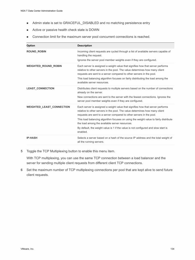
n Admin state is set to GRACEFUL_DISABLED and no matching persistence entry
n Active or passive health check state is DOWN
n Connection limit for the maximum server pool concurrent connections is reached.
Option Description
ROUND_ROBIN Incoming client requests are cycled through a list of available servers capable of handling the request.
Ignores the server pool member weights even if they are configured.
WEIGHTED_ROUND_ROBIN Each server is assigned a weight value that signifies how that server performs relative to other servers in the pool. The value determines how many client requests are sent to a server compared to other servers in the pool.
This load balancing algorithm focuses on fairly distributing the load among the available server resources.
LEAST_CONNECTION Distributes client requests to multiple servers based on the number of connections already on the server.
New connections are sent to the server with the fewest connections. Ignores the server pool member weights even if they are configured.
WEIGHTED_LEAST_CONNECTION Each server is assigned a weight value that signifies how that server performs relative to other servers in the pool. The value determines how many client requests are sent to a server compared to other servers in the pool.
This load balancing algorithm focuses on using the weight value to fairly distribute the load among the available server resources.
By default, the weight value is 1 if the value is not configured and slow start is enabled.
IP-HASH Selects a server based on a hash of the source IP address and the total weight of all the running servers.
5 Toggle the TCP Multiplexing button to enable this menu item.
With TCP multiplexing, you can use the same TCP connection between a load balancer and the server for sending multiple client requests from different client TCP connections.
6 Set the maximum number of TCP multiplexing connections per pool that are kept alive to send future client requests.
NSX-T Data Center Administration Guide
VMware, Inc. 134

7 Select the Source NAT (SNAT) mode.
Depending on the topology, SNAT might be required so that the load balancer receives the traffic from the server destined to the client. SNAT can be enabled per server pool.
Mode Description
Transparent Mode Load balancer uses the client IP address and port spoofing while establishing connections to the servers.
SNAT is not required.
Auto Map Mode Load Balancer uses the interface IP address and ephemeral port to continue the communication with a client initially connected to one of the server's established listening ports.
SNAT is required.
Enable port overloading to allow the same SNAT IP and port to be used for multiple connections if the tuple (source IP, source port, destination IP, destination port, and IP protocol) is unique after the SNAT process is performed.
You can also set the port overload factor to allow the maximum number of times a port can be used simultaneously for multiple connections.
IP List Mode Specify a single IP address range, for example, 1.1.1.1-1.1.1.10 to be used for SNAT while connecting to any of the servers in the pool.
By default, from 4000 through 64000 port range is used for all configured SNAT IP addresses. Port ranges from 1000 through 4000 are reserved for purposes such as, health checks and connections initiated from Linux applications. If multiple IP addresses are present, then they are selected in a Round Robin manner.
Enable port overloading to allow the same SNAT IP and port to be used for multiple connections if the tuple (source IP, source port, destination IP, destination port, and IP protocol) is unique after the SNAT process is performed.
You can also set the port overload factor to allow the maximum number of times a port can be used simultaneously for multiple connections.
8 Select the server pool members.
Server pool consists of single or multiple pool members. Each pool member has an IP address and a port.
Each server pool member can be configured with a weight for use in the load balancing algorithm. The weight indicates how much more or less load a given pool member can handle relative to other members in the same pool.
Designating a pool member as a backup member works with the health monitor to provide an active/standby state. Traffic failover occurs for backup members if active members fail a health check.
Option Description
Static Click Add to include a static pool member.
You can also clone an existing static pool member.
Dynamic Select the NSGroup from the drop-down menu.
The server pool membership criteria is defined in the group. You can optionally, define the maximum group IP address list.
NSX-T Data Center Administration Guide
VMware, Inc. 135

9 Enter the minimum number of active members the server pool must always maintain.
10 Select an active and passive health monitor for the server pool from the drop-down menu.
11 Click Finish.
Configuring Virtual Server ComponentsWith the virtual server there are several components that you can configure such as, application profiles, persistent profiles, and load balancer rules.
Clients Load Balancer Server 1
Server 2Virtual
Server 1
1
4
2
3Health Check
Server 3
Pool 1
Tier-1
Figure 10-2. Virtual Server Components
Load Balancer (LB)
Virtual Server
Application Profile
Persistence Profile
Client-SSL Profile
LB Rules
Server-SSL Profile
Pool
Fast TCP
Fast UDP
HTTP
Source-IP
Cookie
Configure Application ProfilesApplication profiles are associated with virtual servers to enhance load balancing network traffic and simplify traffic-management tasks.
NSX-T Data Center Administration Guide
VMware, Inc. 136

Application profiles define the behavior of a particular type of network traffic. The associated virtual server processes network traffic according to the values specified in the application profile. Fast TCP, Fast UDP, and HTTP application profiles are the supported types of profiles.
TCP application profile is used by default when no application profile is associated to a virtual server. TCP and UDP application profiles are used when an application is running on a TCP or UDP protocol and does not require any application level load balancing such as, HTTP URL load balancing. These profiles are also used when you only want Layer 4 load balancing, which has faster performance and supports connection mirroring.
HTTP application profile is used for both HTTP and HTTPS applications when the load balancer needs to take actions based on Layer 7 such as, load balancing all images requests to a specific server pool member or terminating HTTPS to offload SSL from pool members. Unlike the TCP application profile, the HTTP application profile terminates the client TCP connection before selecting the server pool member.
Figure 10-3. Layer 4 TCP and UDP Application Profile
Clients Load Balancer
Layer 4 VIP(TCP/UDP)
Server 1
Server 2Virtual Server 1
Health Check
Server 3
Pool 1
Tier-1
Figure 10-4. Layer 7 HTTPS Application Profile
Clients Load Balancer
Layer 7 VIP(HTTP/HTTPS)
Server 1
Server 2Virtual
Server 1
Health Check
Server 3
Pool 1
Tier-1
Procedure
1 From your browser, log in with admin privileges to an NSX Manager at https://nsx-manager-ip-address.
NSX-T Data Center Administration Guide
VMware, Inc. 137

2 Select Networking > Load Balancer > Profiles > Application Profiles.
3 Create a Fast TCP application profile.
a Select Add > Fast TCP Profile from the drop-down menu.
b Enter a name and a description for the Fast TCP application profile.
c Complete the application profile details.
You can also accept the default FAST TCP profile settings.
Option Description
Connection Idle Timeout Enter the time in seconds on how long the server can remain idle after a TCP connection is established.
Set the idle time to the actual application idle time and add a few more seconds so that the load balancer does not close its connections before the application does.
Connection Close Timeout Enter the time in seconds that the TCP connection both FINs or RST must be kept for an application before closing the connection.
A short closing timeout might be required to support fast connection rates.
HA Flow Mirroring Toggle the button to make all the flows to the associated virtual server mirrored to the HA standby node.
d Click OK.
4 Create a Fast UDP application profile.
You can also accept the default UDP profile settings.
a Select Add > Fast UDP Profile from the drop-down menu.
b Enter a name and a description for the Fast UDP application profile.
c Complete the application profile details.
Option Description
Idle Timeout Enter the time in seconds on how long the server can remain idle after a UDP connection is established.
UDP is a connectionless protocol. For load balancing purposes, all the UDP packets with the same flow signature such as, source and destination IP address or ports and IP protocol received within the idle timeout period are considered to belong to the same connection and sent to the same server.
If no packets are received during the idle timeout period, the connection which is an association between the flow signature and the selected server is closed.
HA Flow Mirroring Toggle the button to make all the flows to the associated virtual server mirrored to the HA standby node.
d Click OK.
5 Create an HTTP application profile.
You can also accept the default HTTP profile settings.
NSX-T Data Center Administration Guide
VMware, Inc. 138

HTTP application profile is used for both HTTP and HTTPS applications.
a Select Add > Fast HTTP Profile from the drop-down menu.
b Enter a name and a description for the HTTP application profile.
NSX-T Data Center Administration Guide
VMware, Inc. 139

c Complete the application profile details.
Option Description
Redirection n None - If a website is temporarily down, user receives a page not found error message.
n HTTP Redirect - If a website is temporarily down or has moved, incoming requests for that virtual server can be temporarily redirected to a URL specified here. Only a static redirection is supported.
For example, if HTTP Redirect is set to http://sitedown.abc.com/sorry.html, then irrespective of the actual request, for example, http://original_app.site.com/home.html or http://original_app.site.com/somepage.html, incoming requests are redirected to the specified URL when the original website is down.
n HTTP to HTTPS Redirect - Certain secure applications might want to force communication over SSL, but instead of rejecting non-SSL connections, they can redirect the client request to use SSL. With HTTP to HTTPS Redirect, you can preserve both the host and URI paths and redirect the client request to use SSL.
For HTTP to HTTPS redirect, the HTTPS virtual server must have port 443 and the same virtual server IP address must be configured on the same load balancer.
For example, a client request for http://app.com/path/page.html is redirected to https://app.com/path/page.html. If either the host name or the URI must be modified while redirecting, for example, redirect to https://secure.app.com/path/page.html, then load balancing rules must be used.
X-Forwarded-For (XFF) n INSERT - If the XFF HTTP header is not present in the incoming request then the load balancer inserts a new XFF header with the client IP address.
n REPLACE - If the XFF HTTP header is already present in the incoming request then the load balancer can replace the header.
Web servers log each request they handle with the requesting client IP address. These logs are used for debugging and analytics purposes. If the deployment topology requires SNAT on the load balancer, then server uses the client SNAT IP address which defeats the purpose of logging.
As a workaround, the load balancer can be configured to insert XFF HTTP header with the original client IP address. Servers can be configured to log the IP address in the XFF header instead of the source IP address of the connection.
Connection Idle Timeout Enter the time in seconds on how long an HTTP application can remain idle, instead of the TCP socket setting which must be configured in the TCP application profile.
Request Header Size Specify the maximum buffer size in bytes used to store HTTP request headers.
NTLM Authentication Toggle the button for the load balancer to turn off TCP multiplexing and enable HTTP keep-alive.
NTLM is an authentication protocol that can be used over HTTP. For load balancing with NTLM authentication, TCP multiplexing must be disabled for the server pools hosting NTLM-based applications. Otherwise, a server-side connection established with one client's credentials can potentially be used for serving another client's requests.
NSX-T Data Center Administration Guide
VMware, Inc. 140

Option Description
If NTLM is enabled in the profile and associated to a virtual server, and TCP multiplexing is enabled at the server pool, then NTLM takes precedence. TCP multiplexing is not performed for that virtual server. However, if the same pool is associated to another non-NTLM virtual server, then TCP multiplexing is available for connections to that virtual server.
If the client uses HTTP/1.0, the load balancer upgrades to HTTP/1.1 protocol and the HTTP keep-alive is set. All HTTP requests received on the same client-side TCP connection are sent to the same server over a single TCP connection to ensure that reauthorization is not required.
d Click OK.
Configure Persistent ProfilesTo ensure stability of stateful applications, load balancers implement persistence which directs all related connections to the same server. Different types of persistence are supported to address different types of application needs.
Some applications maintain the server state such as, shopping carts. Such state might be per client and identified by the client IP address or per HTTP session. Applications might access or modify this state while processing subsequent related connections from the same client or HTTP session.
Source IP persistence profile tracks sessions based on the source IP address. When a client requests a connection to a virtual server that enables the source address persistence, the load balancer checks if that client was previously connected, if so, returns the client to the same server. If not, you can select a server pool member based on the pool load balancing algorithm. Source IP persistence profile is used by Layer 4 and Layer 7 virtual servers.
Cookie persistence profile inserts a unique cookie to identify the session the first time a client accesses the site. The HTTP cookie is forwarded by the client in subsequent requests and the load balancer uses that information to provide the cookie persistence. Cookie persistence profile can only be used by Layer 7 virtual servers.
Client 1
Client 2
Load Balancer
Layer 4 VIP or Layer 7 VIP
Server 1
Server 2Virtual Server 1
Health Check
Server 3
Pool 1
Tier-1
NSX-T Data Center Administration Guide
VMware, Inc. 141

Procedure
1 From your browser, log in with admin privileges to an NSX Manager at https://nsx-manager-ip-address.
2 Select Networking > Load Balancer > Profiles > Persistence Profiles.
3 Create a Source IP persistence profile.
a Select Add > Source IP Persistence from the drop-down menu.
b Enter a name and a description for the Source IP persistence profile.
c Complete the persistence profile details.
You can also accept the default Source IP profile settings.
Option Description
Share Persistence Toggle the button to share the persistence so that all virtual servers this profile is associated with can share the persistence table.
If persistence sharing is not enabled in the Source IP persistence profile associated to a virtual server, each virtual server that the profile is associated to maintain a private persistence table.
Persistence Entry Timeout Enter the persistence expiration time in seconds.
The load balancer persistence table maintains entries to record that client requests are directed to the same server.
n If no new connection requests are received from the same client within the timeout period, the persistence entry expires and is deleted.
n If a new connection request from the same client is received within the timeout period, the timer is reset, and the client request is sent to a sticky pool member.
After the timeout period has expired, new connection requests are sent to a server allocated by the load balancing algorithm. For the L7 load balancing TCP source IP persistence scenario, the persistence entry times out if no new TCP connections are made for some time, even if the existing connections are still alive.
HA Persistence Mirroring Toggle the button to synchronize persistence entries to the HA peer.
Purge Entries When Full Purge entries when the persistence table is full.
A large timeout value might lead to the persistence table quickly filling up when the traffic is heavy. When the persistence table fills up, the oldest entry is deleted to accept the newest entry.
d Click OK.
4 Create a Cookie persistence profile.
a Select Add > Cookie Persistence from the drop-down menu.
b Enter a name and a description for the Cookie persistence profile.
NSX-T Data Center Administration Guide
VMware, Inc. 142

c Toggle the Share Persistence button to share persistence across multiple virtual servers that are associated to the same pool members.
The Cookie persistence profile inserts a cookie with the format, <name>.<profile-id>.<pool-id>.
If the persistence shared is not enabled in the Cookie persistence profile associated with a virtual server, the private Cookie persistence for each virtual server is used and is qualified by the pool member. The load balancer inserts a cookie with the format, <name>.<virtual_server_id>.<pool_id>.
d Click Next.
e Complete the persistence profile details.
Option Description
Cookie Mode Select a mode from the drop-down menu.
n INSERT - Adds a unique cookie to identify the session.
n PREFIX - Appends to the existing HTTP cookie information.
n REWRITE - Rewrites the existing HTTP cookie information.
Cookie Name Enter the cookie name.
Cookie Domain Enter the domain name.
HTTP cookie domain can be configured only in the INSERT mode.
Cookie Path Enter the cookie URL path.
HTTP cookie path can be set only in the INSERT mode.
Cookie Garbling Encrypt the cookie server IP address and port information.
Toggle the button to disable encryption. When garbling is disabled, the cookie server IP address and port information is in a plain text.
Cookie Fallback Select a new server to handle a client request if the cookie points to a server that is in a DISABLED or is in a DOWN state.
Toggle the button so that the client request is rejected if cookie points to a server that is in a DISABLED or is in a DOWN state.
f Complete the Cookie expiry details.
Option Description
Cookie Time Type Select a cookie time type from the drop-down menu.
Both session cookie and persistence cookie types expire when the browser is closed.
Maximum Idle Time Enter the time in seconds that the cookie can be idle before a cookie expires.
g Click Finish.
NSX-T Data Center Administration Guide
VMware, Inc. 143

Configure SSL ProfileSSL profiles configure application-independent SSL properties such as, cipher lists and reuse these lists across multiple applications. SSL properties are different when the load balancer is acting as a client and as a server, as a result separate SSL profiles for client-side and server-side are supported.
Note SSL profile is not supported in the NSX-T Data Center limited export release.
Client-side SSL profile refers to the load balancer acting as an SSL server and terminating the client SSL connection. Server-side SSL profile refers to the load balancer acting as a client and establishing a connection to the server.
You can specify a cipher list on both the client-side and server-side SSL profiles.
SSL session caching allows the SSL client and server to reuse previously negotiated security parameters avoiding the expensive public key operation during the SSL handshake. SSL session caching is disabled by default on both the client-side and server-side.
SSL session tickets are an alternate mechanism that allow the SSL client and server to reuse previously negotiated session parameters. In SSL session tickets, the client and server negotiate whether they support SSL session tickets during the handshake exchange. If supported by both, server can send an SSL ticket, which includes encrypted SSL session parameters to the client. The client can use that ticket in subsequent connections to reuse the session. SSL session tickets are enabled on the client-side and disabled on the server-side.
Figure 10-5. SSL Offloading
ClientsLoad Balancer
Layer 7 VIPServer 1
Server 2Virtual
Server 1
1
Health Check
Server 3
Pool 1
Tier-1
HTTPHTTPS(Client SSL
Profile)
NSX-T Data Center Administration Guide
VMware, Inc. 144
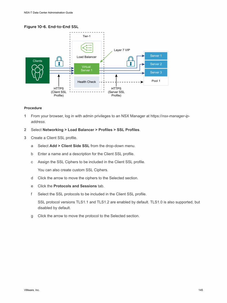
Figure 10-6. End-to-End SSL
1
HTTPS(Server SSL
Profile)
ClientsLoad Balancer
Layer 7 VIP
Server 1
Server 2Virtual
Server 1
Health Check
Server 3
Pool 1
Tier-1
HTTPS(Client SSL
Profile)
Procedure
1 From your browser, log in with admin privileges to an NSX Manager at https://nsx-manager-ip-address.
2 Select Networking > Load Balancer > Profiles > SSL Profiles.
3 Create a Client SSL profile.
a Select Add > Client Side SSL from the drop-down menu.
b Enter a name and a description for the Client SSL profile.
c Assign the SSL Ciphers to be included in the Client SSL profile.
You can also create custom SSL Ciphers.
d Click the arrow to move the ciphers to the Selected section.
e Click the Protocols and Sessions tab.
f Select the SSL protocols to be included in the Client SSL profile.
SSL protocol versions TLS1.1 and TLS1.2 are enabled by default. TLS1.0 is also supported, but disabled by default.
g Click the arrow to move the protocol to the Selected section.
NSX-T Data Center Administration Guide
VMware, Inc. 145

h Complete the SSL protocol details.
You can also accept the default SSL profile settings.
Option Description
Session Caching SSL session caching allows the SSL client and server to reuse previously negotiated security parameters avoiding the expensive public key operation during an SSL handshake.
Session Cache Entry Timeout Enter the cache timeout in seconds to specify how long the SSL session parameters must be kept and can be reused.
Prefer Server Cipher Toggle the button so that the server can select the first supported cipher from the list it can support.
During an SSL handshake, the client sends an ordered list of supported ciphers to the server.
i Click OK.
4 Create a Server SSL profile.
a Select Add > Server Side SSL from the drop-down menu.
b Enter a name and a description for the Server SSL profile.
c Select the SSL Ciphers to be included in the Server SSL profile.
You can also create custom SSL Ciphers.
d Click the arrow to move the ciphers to the Selected section.
e Click the Protocols and Sessions tab.
f Select the SSL protocols to be included in the Server SSL profile.
SSL protocol versions TLS1.1 and TLS1.2 are enabled by default. TLS1.0 is also supported, but disabled by default.
g Click the arrow to move the protocol to the Selected section.
h Accept the default session caching setting.
SSL session caching allows the SSL client and server to reuse previously negotiated security parameters avoiding the expensive public key operation during an SSL handshake.
i Click OK.
Configure Layer 4 Virtual ServersVirtual servers receive all the client connections and distribute them among the servers. A virtual server has an IP address, a port, and a protocol. For Layer 4 virtual servers, lists of ports ranges can be specified instead of a single TCP or UDP port to support complex protocols with dynamic ports.
A Layer 4 virtual server must be associated to a primary server pool, also called a default pool.
NSX-T Data Center Administration Guide
VMware, Inc. 146

If a virtual server status is disabled, any new connection attempts to the virtual server are rejected by sending either a TCP RST for the TCP connection or ICMP error message for UDP. New connections are rejected even if there are matching persistence entries for them. Active connections continue to be processed. If a virtual server is deleted or disassociated from a load balancer, then active connections to that virtual server fail.
Prerequisites
n Verify that application profiles are available. See Configure Application Profiles.
n Verify that persistent profiles are available. See Configure Persistent Profiles.
n Verify that SSL profiles for the client and server are available. See Configure SSL Profile.
n Verify that server pools are available. See Add a Server Pool for Load Balancing.
Procedure
1 From your browser, log in with admin privileges to an NSX Manager at https://nsx-manager-ip-address.
2 Select Networking > Load Balancer > Virtual Servers > Add.
3 Enter a name and a description for the Layer 4 virtual server.
4 Select a Layer 4 protocol from the drop-down menu.
Layer 4 virtual servers support either the Fast TCP or Fast UDP protocol, but not both. For Fast TCP or Fast UDP protocol support on the same IP address and port, for example DNS, a virtual server must be created for each protocol.
Based on the protocol type, the existing application profile is automatically populated.
5 Toggle the Access Log button to enable logging for the Layer 4 virtual server.
6 Click Next.
7 Enter the virtual server IP address and port number.
You can enter the virtual server port number or port range.
NSX-T Data Center Administration Guide
VMware, Inc. 147

8 Complete the advanced properties details.
Option Description
Maximum Concurrent Connection Set the maximum concurrent connection allowed to a virtual server so that the virtual server does not deplete resources of other applications hosted on the same load balancer.
Maximum New Connection Rate Set the maximum new connection to a server pool member so that a virtual server does not deplete resources.
Default Pool Member Port Enter a default pool member port if the pool member port for a virtual server is not defined.
For example, if a virtual server is defined with port range 2000-2999 and the default pool member port range is set as 8000-8999, then an incoming client connection to the virtual server port 2500 is sent to a pool member with a destination port set to 8500.
9 Select an existing server pool from the drop-down menu.
The server pool consists of one or more servers, also called pool members that are similarly configured and running the same application.
10 Select an existing sorry server pool from the drop-down menu.
The sorry server pool serves the request when a load balancer cannot select a backend server to the serve the request from the default pool.
11 Click Next.
12 Select the existing persistence profile from the drop-down menu.
Persistence profile can be enabled on a virtual server to allow related client connections to be sent to the same server.
13 Click Finish.
Configure Layer 7 Virtual ServersVirtual servers receive all the client connections and distribute them among the servers. A virtual server has an IP address, a port, and a protocol TCP.
Load balancer rules are supported for only Layer 7 virtual servers with an HTTP application profile. Different load balancer services can use load balancer rules.
Each load balancer rule consists of single or multiple match conditions and single or multiple actions. If the match conditions are not specified, then the load balancer rule always matches and is used to define default rules. If more than one match condition is specified, then the matching strategy determines if all conditions must match or any one condition must match for the load balancer rule to be considered a match.
Each load balancer rule is implemented at a specific phase of the load balancing processing; HTTP Request Rewrite, HTTP Request Forwarding, and HTTP Response Rewrite. Not all the match conditions and actions are applicable to each phase.
NSX-T Data Center Administration Guide
VMware, Inc. 148

If a virtual server status is disabled, any new connection attempts to the virtual server are rejected by sending either a TCP RST for the TCP connection or ICMP error message for UDP. New connections are rejected even if there are matching persistence entries for them. Active connections continue to be processed. If a virtual server is deleted or disassociated from a load balancer, then active connections to that virtual server fail.
Prerequisites
n Verify that application profiles are available. See Configure Application Profiles.
n Verify that persistent profiles are available. See Configure Persistent Profiles.
n Verify that SSL profiles for the client and server are available. See Configure SSL Profile.
n Verify that server pools are available. See Add a Server Pool for Load Balancing.
n Verify that CA and client certificate are available. See Create a Certificate Signing Request File.
n Verify that a certification revocation list (CRL) is available. See Import a Certificate Revocation List.
n Configure Layer 7 Virtual Server Pool and Rules
With Layer 7 virtual servers, you can optionally configure load balancer rules and customize load balancing behavior using match or action rules.
n Configure Layer 7 Virtual Server Load Balancing Profiles
With Layer 7 virtual servers, you can optionally configure load balancer persistence, client-side SSL, and server-side SSL profiles.
Procedure
1 From your browser, log in with admin privileges to an NSX Manager at https://nsx-manager-ip-address.
2 Select Networking > Load Balancer > Virtual Servers > Add.
3 Enter a name and a description for the Layer 7 virtual server.
4 Select the Layer 7 menu item.
Layer 7 virtual servers support the HTTP and HTTPS protocols.
The existing HTTP application profile is automatically populated.
5 (Optional) Click Next to configure server pool and load balancing profiles.
6 Click Finish.
Configure Layer 7 Virtual Server Pool and Rules
With Layer 7 virtual servers, you can optionally configure load balancer rules and customize load balancing behavior using match or action rules.
Load Balancer rules support REGEX for match types. PCRE style REGEX patters is supported with a few limitations on advanced use cases. When REGEX is used in match conditions, named capturing groups are supported.
NSX-T Data Center Administration Guide
VMware, Inc. 149

REGEX restrictions include:
n Character unions and intersections are not supported. For example, do not use [a-z[0-9]] and [a-z&&[aeiou]] instead use [a-z0-9] and [aeiou] respectively.
n Only 9 back references are supported and \1 through \9 can be used to refer to them.
n Use \0dd format to match octal characters, not the \ddd format.
n Embedded flags are not supported at the top level, they are only supported within groups. For example, do not use "Case (?i:s)ensitive" instead use "Case ((?i:s)ensitive)".
n Preprocessing operations \l, \u, \L, \U are not supported. Where \l - lowercase next char \u - uppercase next char \L - lower case until \E \U - upper case to \E.
n (?(condition)X), (?{code}), (??{Code}) and (?#comment) are not supported.
n Predefined Unicode character class \X is not supported
n Using named character construct for Unicode characters is not supported. For example, do not use \N{name} instead use \u2018.
When REGEX is used in match conditions, named capturing groups are supported. For example, REGEX match pattern /news/(?<year>\d+)-(?<month>\d+)-(?<day>\d+)/(?<article>.*) can be used to match a URI like /news/2018-06-15/news1234.html.
Then variables are set as follows, $year = "2018" $month = "06" $day = "15" $article = "news1234.html". After the variables are set, these variables can be used in load balancer rule actions. For example, URI can be rewritten using the matched variables like, /news.py?year=$year&month=$month&day=$day&article=$article. Then the URI gets rewritten as /news.py?year=2018&month=06&day=15&article=news1234.html.
Rewrite actions can use a combination of named capturing groups and built-in variables. For example, URI can be written as /news.py?year=$year&month=$month&day=$day&article=$article&user_ip=$_remote_addr. Then the example URI gets rewritten as /news.py?year=2018&month=06&day=15&article=news1234.html&user_ip=1.1.1.1.
Note For named capturing groups, the name cannot start with an _ character.
In addition to named capturing groups, the following built-in variables can be used in rewrite actions. All the built-in variable names start with _.
n $_args - arguments from the request
n $_cookie_<name> - value of <name> cookie
n $_host - in the order of precedence - host name from the request line, or host name from the "Host" request header field, or the server name matching a request
n $_hostname - host name
n $_http_<name> - arbitrary request header field and <name> is the field name converted to lower case with dashes replaced by underscores
n $_https - "on" if connection operates in SSL mode, or "" otherwise
NSX-T Data Center Administration Guide
VMware, Inc. 150

n $_is_args - "?" if a request line has arguments, or "" otherwise
n $_query_string - same as $_args
n $_remote_addr - client address
n $_remote_port - client port
n $_request_uri - full original request URI (with arguments)
n $_scheme - request scheme, "http" or "https"
n $_server_addr - address of the server which accepted a request
n $_server_name - name of the server which accepted a request
n $_server_port - port of the server which accepted a request
n $_server_protocol - request protocol, usually "HTTP/1.0" or "HTTP/1.1"
n $_ssl_client_cert - returns the client certificate in the PEM format for an established SSL connection, with each line except the first prepended with the tab character
n $_ssl_server_name - returns the server name requested through SNI
n $_uri - URI path in request
Prerequisites
Verify a Layer 7 virtual server is available. See Configure Layer 7 Virtual Servers.
Procedure
1 Open the Layer 7 virtual server.
2 Skip to the Virtual Server Identifiers page.
3 Enter the virtual server IP address and port number.
You can enter the virtual server port number or port range.
4 Complete the advanced properties details.
Option Description
Maximum Concurrent Connection Set the maximum concurrent connection allowed to a virtual server so that the virtual server does not deplete resources of other applications hosted on the same load balancer.
Maximum New Connection Rate Set the maximum new connection to a server pool member so that a virtual server does not deplete resources.
Default Pool Member Port Enter a default pool member port if the pool member port for a virtual server is not defined.
For example, if a virtual server is defined with port range 2000–2999 and the default pool member port range is set as 8000-8999, then an incoming client connection to the virtual server port 2500 is sent to a pool member with a destination port set to 8500.
NSX-T Data Center Administration Guide
VMware, Inc. 151

5 (Optional) Select an existing default server pool from the drop-down menu.
The server pool consists of one or more servers, called pool members that are similarly configured and running the same application.
6 Click Add to configure the load balancer rules for the HTTP Request Rewrite phase.
Supported match types are, REGEX, STARTS_WITH, ENDS_WITH, etc and inverse option.
Supported Match Condition Description
HTTP Request Method Match an HTTP request method.
http_request.method - value to match
HTTP Request URI Match an HTTP request URI without query arguments.
http_request.uri - value to match
HTTP Request URI arguments Match an HTTP request URI query argument.
http_request.uri_arguments - value to match
HTTP Request Version Match an HTTP request version.
http_request.version - value to match
HTTP Request Header Match any HTTP request header.
http_request.header_name - header name to match
http_request.header_value - value to match
HTTP Request Payload Match an HTTP request body content.
http_request.body_value - value to match
TCP Header Fields Match a TCP source or the destination port.
tcp_header.source_port - source port to match
tcp_header.destination_port - destination port to match
IP Header Fields Match an IP source or destination address.
ip_header.source_address - source address to match
ip_header.destination_address - destination address to match
Action Description
HTTP Request URI Rewrite Modify an URI.
http_request.uri - URI (without query arguments) to write
http_request.uri_args - URI query arguments to write
HTTP Request Header Rewrite Modify value of an HTTP header.
http_request.header_name - header name
http_request.header_value - value to write
NSX-T Data Center Administration Guide
VMware, Inc. 152

7 Click Add to configure the load balancer rules for the HTTP Request Forwarding.
All match values accept regular expressions.
Supported Match Condition Description
HTTP Request Method Match an HTTP request method.
http_request.method - value to match
HTTP Request URI Match an HTTP request URI.
http_request.uri - value to match
HTTP Request URI args Match an HTTP request URI query argument.
http_request.uri_args - value to match
HTTP Request Version Match an HTTP request version.
http_request.version - value to match
HTTP Request Header Match any HTTP request header.
http_request.header_name - header name to match
http_request.header_value - value to match
HTTP Request Payload Match an HTTP request body content.
http_request.body_value - value to match
TCP Header Fields Match a TCP source or the destination port.
tcp_header.source_port - source port to match
tcp_header.destination_port - destination port to match
IP Header Fields Match an IP source address.
ip_header.source_address - source address to match
Action Description
Reject Reject a request, for example, by setting status to 5xx.
http_forward.reply_status - HTTP status code used to reject
http_forward.reply_message - HTTP rejection message
Redirect Redirect a request. Status code must be set to 3xx.
http_forward.redirect_status - HTTP status code for redirect
http_forward.redirect_url - HTTP redirect URL
Select Pool Force the request to a specific server pool. Specified pool member's configured algorithm (predictor) is used to select a server within the server pool.
http_forward.select_pool - server pool UUID
NSX-T Data Center Administration Guide
VMware, Inc. 153
8 Click Add to configure the load balancer rules for the HTTP Response Rewrite.
All match values accept regular expressions.
Supported Match Condition Description
HTTP Response Header Match any HTTP response header.
http_response.header_name - header name to match
http_response.header_value - value to match
Action Description
HTTP Response Header Rewrite Modify the value of an HTTP response header.
http_response.header_name - header name
http_response.header_value - value to write
9 (Optional) Click Next to configure load balancing profiles.
10 Click Finish.
Configure Layer 7 Virtual Server Load Balancing Profiles
With Layer 7 virtual servers, you can optionally configure load balancer persistence, client-side SSL, and server-side SSL profiles.
Note SSL profile is not supported in the NSX-T Data Center 2.2 limited export release.
If a client-side SSL profile binding is configured on a virtual server but not a server-side SSL profile binding, then the virtual server operates in an SSL-terminate mode, which has an encrypted connection to the client and plain text connection to the server. If both the client-side and server-side SSL profile bindings are configured, then the virtual server operates in SSL-proxy mode, which has an encrypted connection both to the client and the server.
Associating server-side SSL profile binding without associating a client-side SSL profile binding is currently not supported. If a client-side and a server-side SSL profile binding is not associated with a virtual server and the application is SSL-based, then the virtual server operates in an SSL-unaware mode. In this case, the virtual server must be configured for Layer 4. For example, the virtual server can be associated to a fast TCP profile.
Prerequisites
Verify a Layer 7 virtual server is available. See Configure Layer 7 Virtual Servers.
Procedure
1 Open the Layer 7 virtual server.
2 Skip to the Load Balancing Profiles page.
3 Toggle the Persistence button to enable the profile.
Persistence profile allows related client connections to be sent to the same server.
NSX-T Data Center Administration Guide
VMware, Inc. 154

4 Select either the Source IP Persistence or Cookie Persistence profile.
5 Select the existing persistence profile from the drop-down menu.
6 Click Next.
7 Toggle the Client Side SSL button to enable the profile.
Client-side SSL profile binding allows multiple certificates, for different host names to be associated to the same virtual server.
The associated Client-side SSL profile is automatically populated.
8 Select a default certificate from the drop-down menu.
This certificate is used if the server does not host multiple host names on the same IP address or if the client does not support Server Name Indication (SNI) extension.
9 Select the available SNI certificate and click the arrow to move the certificate to the Selected section.
10 (Optional) Toggle the Mandatory Client Authentication to enable this menu item.
11 Select the available CA certificate and click the arrow to move the certificate to the Selected section.
12 Set the certificate chain depth to verify the depth in the server certificates chain.
13 Select the available CRL and click the arrow to move the certificate to the Selected section.
A CRL can be configured to disallow compromised server certificates.
14 Click Next.
15 Toggle the Server Side SSL button to enable the profile.
The associated Server-side SSL profile is automatically populated.
16 Select a client certificate from the drop-down menu.
The client certificate is used if the server does not host multiple host names on the same IP address or if the client does not support Server Name Indication (SNI) extension.
17 Select the available SNI certificate and click the arrow to move the certificate to the Selected section.
18 (Optional) Toggle the Server Authentication to enable this menu item.
Server-side SSL profile binding specifies whether the server certificate presented to the load balancer during the SSL handshake must be validated or not. When validation is enabled, the server certificate must be signed by one of the trusted CAs whose self-signed certificates are specified in the same server-side SSL profile binding.
19 Select the available CA certificate and click the arrow to move the certificate to the Selected section.
20 Set the certificate chain depth to verify the depth in the server certificates chain.
21 Select the available CRL and click the arrow to move the certificate to the Selected section.
A CRL can be configured to disallow compromised server certificates. OCSP and OCSP stapling are not supported on the server-side.
22 Click Finish.
NSX-T Data Center Administration Guide
VMware, Inc. 155

DHCP 11DHCP (Dynamic Host Configuration Protocol) allows clients to automatically obtain network configuration, such as IP address, subnet mask, default gateway, and DNS configuration, from a DHCP server.
You can create DHCP servers to handle DHCP requests and create DHCP relay services to relay DHCP traffic to external DHCP servers. However, you should not configure a DHCP server on a logical switch and also configure a DHCP relay service on a router port that the same logical switch is connected to. In such a scenario, DHCP requests will only go to the DHCP relay service.
If you configure DHCP servers, to improve security, configure a DFW rule to allow traffic on UDP ports 67 and 68 only for valid DHCP server IP addresses.
Note A DFW rule that has Logical Switch/Logical Port/NSGroup as the source, Any as the destination, and is configured to drop DHCP packets for ports 67 and 68, will fail to block DHCP traffic. To block DHCP traffic, configure Any as the source as well as the destination.
This chapter includes the following topics:
n Create a DHCP Server Profile
n Create a DHCP Server
n Attach a DHCP Server to a Logical Switch
n Detach a DHCP Server from a Logical Switch
n Create a DHCP Relay Profile
n Create a DHCP Relay Service
n Add a DHCP Service to a Logical Router Port
Create a DHCP Server ProfileA DHCP server profile specifies an NSX Edge cluster or members of an NSX Edge cluster. A DHCP server with this profile services DHCP requests from VMs on logical switches that are connected to the NSX Edge nodes that are specified in the profile.
Procedure
1 From your browser, log in with admin privileges to an NSX Manager at https://nsx-manager-ip-address.
2 Select Networking > DHCP from the navigation panel.
VMware, Inc. 156

3 Click Server Profiles and click Add.
4 Enter a name and optional description.
5 Select an NSX Edge cluster from the drop-down menu.
6 (Optional) Select members of the NSX Edge cluster.
You can specify up to 2 members.
What to do next
Create a DHCP server. See Create a DHCP Server.
Create a DHCP ServerYou can create DHCP servers to service DHCP requests from VMs that are connected to logical switches.
Procedure
1 From your browser, log in with admin privileges to an NSX Manager at https://nsx-manager-ip-address.
2 Select Networking > DHCP from the navigation panel.
3 Click Servers and click Add.
4 Enter a name and optional description.
5 Enter the IP address of the DHCP server and its subnet mask in CIDR format.
For example, enter 192.168.1.2/24.
6 (Required) Select a DHCP profile from the drop-down menu.
7 (Optional) Enter common options such as domain name, default gateway, DNS servers, and subnet mask.
8 (Optional) Enter classless static route options.
9 (Optional) Enter other options.
10 Click Save.
11 Select the newly created DHCP server.
12 Expand the IP Pools section.
13 Click Add to add IP ranges, default gateway, lease duration, warning threshold, error threshold, classless static route option, and other options.
14 Expand the Static Bindings section.
15 Click Add to add static bindings between MAC addresses and IP addresses, default gateway, hostname, lease duration, classless static route option, and other options.
NSX-T Data Center Administration Guide
VMware, Inc. 157

What to do next
Attach a DHCP server to a logical switch. See Attach a DHCP Server to a Logical Switch.
Attach a DHCP Server to a Logical SwitchYou must attach a DHCP server to a logical switch before the DHCP server can process DHCP requests from VMs connected to the switch. DHCP server is not supported on VLAN logical switches.
Procedure
1 From your browser, log in with admin privileges to an NSX Manager at https://nsx-manager-ip-address.
2 Select Networking > Switching from the navigation panel.
3 Click the logical switch that you intend to attach a DHCP server to.
4 Click Actions > Attach DHCP Server.
Detach a DHCP Server from a Logical SwitchYou can detach a DHCP server from a logical switch to reconfigure your environment.
Procedure
1 From your browser, log in with admin privileges to an NSX Manager at https://nsx-manager-ip-address.
2 Select Networking > Switching from the navigation panel.
3 Click the logical switch that you intend to detach a DHCP server from.
4 Click Actions > Detach DHCP Server.
Create a DHCP Relay ProfileA DHCP relay profile specifies one or more external DHCP servers. When you create a DHCP relay service, you must specify a DHCP relay profile.
Procedure
1 From your browser, log in with admin privileges to an NSX Manager at https://nsx-manager-ip-address.
2 Select Networking > DHCP from the navigation panel.
3 Click Relay Profiles and click Add.
4 Enter a name and optional description.
5 Enter one or more external DHCP server addresses.
NSX-T Data Center Administration Guide
VMware, Inc. 158

What to do next
Create a DHCP relay service. See Create a DHCP Relay Service.
Create a DHCP Relay ServiceYou can create a DHCP relay service to relay traffic between DHCP clients and DHCP servers that are not created in NSX-T Data Center.
Procedure
1 From your browser, log in with admin privileges to an NSX Manager at https://nsx-manager-ip-address.
2 Select Networking > DHCP from the navigation panel.
3 Click Relay Services and click Add.
4 Enter a name and optional description.
5 Select a DHCP relay profile from the drop-down menu.
What to do next
Add a DHCP service to a logical router port. See Add a DHCP Service to a Logical Router Port.
Add a DHCP Service to a Logical Router PortWhen you add a DHCP relay service to a logical router port, VMs on the logical switch that is attached to that port can communicate with the DHCP servers that are configured in the relay service.
Prerequisites
n Verify you have a configured DHCP relay service. See Create a DHCP Relay Service.
Procedure
1 From your browser, log in with admin privileges to an NSX Manager at https://nsx-manager-ip-address.
2 Select Networking > Routing from the navigation panel.
3 Select the router that is connected to the desired logical switch and click the Configuration tab.
4 Select the router port that connects to the desired logical switch and click Edit.
5 Select a DHCP relay service from the DHCP Service drop-down list and click Save.
The logical router port displays the DHCP relay service in the DHCP Service column.
You can also select a DHCP relay service when you add a new logical router port.
NSX-T Data Center Administration Guide
VMware, Inc. 159

Metadata Proxies 12With a metadata proxy server, VM instances can retrieve instance-specific metadata from an OpenStack Nova API server.
The following steps describe how a metadata proxy works:
1 A VM sends an HTTP GET to http://169.254.169.254:80 to request some metadata.
2 The metadata proxy server that is connected to the same logical switch as the VM reads the request, makes appropriate changes to the headers, and forwards the request to the Nova API server.
3 The Nova API server requests and receives information about the VM from the Neutron server.
4 The Nova API server finds the metadata and sends it to the metadata proxy server.
5 The metadata proxy server forwards the metadata to the VM.
A metadata proxy server runs on an NSX Edge node. For high availability, you can configure metadata proxy to run on two or more NSX Edge nodes in an NSX Edge cluster.
This chapter includes the following topics:
n Add a Metadata Proxy Server
n Attach a Metadata Proxy Server to a Logical Switch
n Detach a Metadata Proxy Server from a Logical Switch
Add a Metadata Proxy ServerA metadata proxy server enables VMs to retrieve metadata from an OpenStack Nova API server.
Prerequisites
Verify that you have created an NSX Edge cluster. For more information, see NSX-T Data Center Installation Guide.
Procedure
1 From your browser, log in with admin privileges to an NSX Manager at https://nsx-manager-ip-address.
2 Select Networking > DHCP from the navigation panel.
3 Click the Metadata Proxies tab.
VMware, Inc. 160

4 Click Add.
5 Enter a name for the metadata proxy server.
6 (Optional) Enter a description.
7 Enter the URL and port for the Nova server.
The valid port range is 3000 - 9000.
8 Enter a value for Secret.
9 Select an NSX Edge cluster from the drop-down list.
10 (Optional) Select members of the NSX Edge cluster.
Example
For example:
What to do next
Attach the metadata proxy server to a logical switch.
Attach a Metadata Proxy Server to a Logical SwitchTo provide metadata proxy services to VMs that are connected to a logical switch, you must attach a metadata proxy server to the switch.
Prerequisites
Verify that you have created a logical switch. For more information, see Create a Logical Switch.
NSX-T Data Center Administration Guide
VMware, Inc. 161

Procedure
1 From your browser, log in with admin privileges to an NSX Manager at https://nsx-manager-ip-address.
2 Select Networking > DHCP from the navigation panel.
3 Click the Metadata Proxies tab.
4 Select a metadata proxy server.
5 Select the menu option Actions > Attach to Logical Switch
6 Select a logical switch from the drop-down list.
You can also attach a metadata proxy server to a logical switch by navigating to Switching > Switches, selecting a switch, and selecting the menu option Actions > Attach Metadata Proxy.
Detach a Metadata Proxy Server from a Logical SwitchTo stop providing metadata proxy services to VMs that are connected to a logical switch or use a different metadata proxy server, you can detach a metadata proxy server from a logical switch.
Procedure
1 From your browser, log in with admin privileges to an NSX Manager at https://nsx-manager-ip-address.
2 Select Networking > DHCP from the navigation panel.
3 Click the Metadata Proxies tab.
4 Select a metadata proxy server.
5 Select the menu option Actions > Detach from Logical Switch
6 Select a logical switch from the drop-down list.
You can also detach a metadata proxy server from a logical switch by navigating to Switching > Switches, selecting a switch, and selecting the menu option Actions > Detach Metadata Proxy.
NSX-T Data Center Administration Guide
VMware, Inc. 162

IP Address Management 13With IP address management (IPAM), you can create IP blocks to support NSX-T Container Plug-in (NCP). For more info about NCP, see the NSX-T Container Plug-in for Kubernetes - Installation and Administration Guide.
This chapter includes the following topics:
n Manage IP Blocks
n Manage Subnets for IP Blocks
Manage IP BlocksSetting up NSX-T Container Plug-in requires that you create IP blocks for the containers.
Procedure
1 From your browser, log in with admin privileges to an NSX Manager at https://nsx-manager-ip-address.
2 Select Networking > IPAM from the navigation panel.
3 To add an IP block, click Add.
a Enter a name and optionally a description.
b Enter an IP block in CIDR format. For example, 10.10.10.0/24.
4 To edit an IP block, click the name of an IP block.
a In the Overview tab, click Edit.
You can change the name, description, or the IP block value.
5 To manage the tags of an IP block, click the name of an IP block.
a In the Overview tab, click Manage.
You can add or delete tags.
6 To delete one or more IP blocks, select the blocks.
a Click Delete.
You cannot delete an IP block that has its subnet allocated.
VMware, Inc. 163

Manage Subnets for IP BlocksYou can add or delete subnets for IP blocks.
Procedure
1 From your browser, log in with admin privileges to an NSX Manager at https://nsx-manager-ip-address.
2 Select Networking > IPAM from the navigation panel.
3 Click the name of an IP block.
4 Click the Subnets tab.
5 To add a subnet, click Add.
a Enter a name and optionally a description.
b Enter the size of the subnet.
6 To delete one or more subnets, select the subnets.
a Click Delete.
NSX-T Data Center Administration Guide
VMware, Inc. 164

NSX Policy 14A policy is a combination of rules and services, where the rules define the criteria for resource access and usage. With NSX policies, you can manage resource access and usage without worrying about low-level details.
This chapter includes the following topics:
n Overview
n Add an Enforcement Point
n Add a Service
n Add a Domain
n Configure Backup of the NSX Policy Manager
n Back Up the NSX Policy Manager
n Restore the NSX Policy Manager
n Associate a vIDM Host with the NSX Policy Manager
n Manage Role Assignments
OverviewWith NSX policies, you can specify rules for objects such as VMs, logical ports, IP addresses, and MAC addresses without worrying about the mechanics of the rules. You manage policies from the NSX Policy Manager rather than the NSX Manager.
Before you configure policies, you must install the NSX Policy Manager. For more information, see the NSX-T Installation Guide. In NSX Policy Manager, you must also add one or more enforcement points, providing information about the NSX Manager where the policies will be applied.
The following example illustrates how to use a policy to manage networking for an application.
The application has three tiers (web, application, and database) and you want the following rules to apply to the application's VMs:
n Allow traffic between the web tier and the application tier.
n Allow traffic between the application tier and the database tier.
n Allow traffic between any system and the web tier.
VMware, Inc. 165

Perform the following steps on the NSX Manager:
n Set the web VMs' workload name as Web followed by some identifying string.
n Set the application VMs' workload name as App followed by some identifying string.
n Set the database VMs' workload name as DB followed by some identifying string.
Perform the following steps on the NSX Policy Manager:
n Create a domain and specify the following:
n Create a group called WebGroup consisting of VMs whose workload name starts with Web.
n Create a group called AppGroup consisting of VMs whose workload name starts with App.
n Create a group called DBGroup consisting of VMs whose workload name starts with DB.
n Specify security policies that control the communication between the groups.
n Verify the domain configuration to make sure that there are no errors.
n Select enforcement points.
After you select the enforcement points, the NSX Policy Manager communicates with the NSX Manager at the enforcement points, which will implement the security policies.
Role-Based Access ControlNSX Policy Manager has two built-in users: admin and audit. You can integrate NSX Policy Manager with VMware Identity Manager (vIDM) and configure role-based access control (RBAC) for users that vIDM manages.
For users managed by vIDM, the authentication policy that applies is the one configured by the vIDM administrator, and not NSX Policy Manager's authentication policy, which applies to the users admin and audit only.
Add an Enforcement PointAn enforcement point is where you want the rules of a policy to apply. In this release, the enforcement point must be an NSX-T installation and an NSX Policy Manager supports only one enforcement point.
Procedure
1 From your browser, log in to the NSX Policy Manager at https://nsx-policy-manager-IP-address.
2 Select System > Enforcement Points from the navigation panel.
3 Click Add.
4 Provide the following information.
Parameter Description
Name The name of the enforcement point.
Credentials The user name and password to log in to the NSX Manager.
NSX-T Data Center Administration Guide
VMware, Inc. 166

Parameter Description
Enforcement Address The IP address of the NSX Manager.
Thumbprint The certificate thumbprint of of the NSX Manager.
5 Click Save.
Add a ServiceA service is a protocol or software component in your environment. A policy contains rules that apply to services.
Examples of a service are FTP. HTTP, AD Server, DHCP Server, Oracle Database, and so on.
Procedure
1 From your browser, log in to the NSX Policy Manager at https://nsx-policy-manager-IP-address.
2 Select Infra > Services from the navigation panel.
3 Click Add New Service.
4 Enter a name for the service.
5 Click Set Service Entries to add service entries.
a Click Add New Service Entry.
b Select a service type.
The available types are IP, IGMP, ICMP, ALG, TCP, and UDP.
c Click the Additional Properties dropdown list to select a property.
You can add additional entries, edit or delete entries.
6 Click Save.
Add a DomainA domain is a logical collection of workloads which serve a common business goal and on which policies need to be applied. It contains a set of groups and their corresponding communication requirements.
If you plan to create multiple large domains (each with more than 200 resultant rules), be sure to deploy them to the enforcement points sequentially, waiting for the realization of each domain before proceeding to the next one. If you deploy these domains using the API, it is recommended that the communication entries be created before a domain is deployed to an enforcement point.
Procedure
1 From your browser, log in to the NSX Policy Manager at https://nsx-policy-manager-IP-address.
2 Select Infra > Domains from the navigation panel.
3 Click Add Domain to add a domain.
NSX-T Data Center Administration Guide
VMware, Inc. 167

4 Specify a name for the domain and optionally a description.
5 Click Next to go to the Workload Groups step.
6 Click Add Group to add one or more workload groups. For each workload group,
a Specify a name.
b Click the Members Type field to select the type of members.
The available choices are Virtual Machine, IP Address, and Membership Criteria.
c For Virtual Machine and IP Address, specify a value.
d For Membership Criteria, click Set Membership Criteria to specify how the members are selected.
7 Click Next to go to the Security step.
8 Click Add New Section to add a firewall section, or Add New Rule to add a firewall rule.
You can add multiple sections and rules.
9 Click Next to go to the Verify Domain Configuration step.
A graphical representation of the domain is displayed.
10 Click Next to go to the Select Enforcement Points step.
11 Select one or more enforcement points.
12 Click Finish to deploy the domain.
Configure Backup of the NSX Policy ManagerYou can back up the NSX Policy Manager to safeguard the data that the Policy Manager stores. Before you can do a backup, you must configure the backup properties.
Prerequisites
Verify that you have the SSH fingerprint of the backup file server. Only an SHA256 hashed ECDSA key is accepted as a fingerprint. See Find the SSH Fingerprint of a Remote Server.
Procedure
1 From your browser, log in to the NSX Policy Manager at https://nsx-policy-manager-IP-address.
2 Select System > Utilities from the navigation panel.
3 Click Configure.
4 Click the Automatic Backup toggle to enable or disable automatic backups.
5 Enter the IP address or host name of the backup file server.
6 Edit the default port if required.
7 Enter the username and password required to log in to the backup file server.
NSX-T Data Center Administration Guide
VMware, Inc. 168

8 In the Destination Directory field, enter the absolute directory path where the backups will be stored.
The directory must already exist.
9 Enter the passphrase used to encrypt the backup data.
You will need this passphrase to restore a backup. If you forget the backup passphrase, you cannot restore any backups.
10 Enter the SSH fingerprint of the server that stores the backups. See Find the SSH Fingerprint of a Remote Server.
11 Click the Schedule tab.
12 Select the frequency.
If you select Weekly, specify the day of the week and time. If you select Interval, specify the interval.
13 Click Save.
Back Up the NSX Policy ManagerYou can back up the NSX Policy Manager automatically or manually.
If you have configured automatic backups, they will occur automatically. This procedure is for manually initiating a backup.
Prerequisites
Verify that you have configured the backup properties. See Configure Backup of the NSX Policy Manager.
Procedure
1 From your browser, log in to the NSX Policy Manager at https://nsx-policy-manager-IP-address.
2 Select System > Utilities from the navigation panel.
3 Click Backup Now.
Restore the NSX Policy ManagerYou can restore the NSX Policy Manager to a state in the past from a backup.
Prerequisites
Verify that you have the SSH fingerprint of the backup file server. Only an SHA256 hashed ECDSA key is accepted as a fingerprint. See Find the SSH Fingerprint of a Remote Server.
Procedure
1 From your browser, log in to the NSX Policy Manager at https://nsx-policy-manager-IP-address.
2 Select System > Utilities from the navigation panel.
3 Click Restore Now.
NSX-T Data Center Administration Guide
VMware, Inc. 169

4 Acknowledge the message about the prerequisites and the risks and click Next.
5 Enter the IP address or host name of the backup server.
6 Change the port number if required.
The default is 22.
7 Enter the user name and password to log in to the server.
8 In the Backup Directory field, enter the absolute directory path where the backup is stored.
9 Enter the passphrase that was used to encrypt the backup data.
10 Enter the SSH fingerprint of the backup server.
11 Click Next.
12 Select a backup.
13 Click Restore.
The status of the restore operation is displayed. If you have deleted or added fabric nodes or transport nodes since the backup, you will be prompted to take certain actions, for example, log in to a node and run a script.
After the restore operation is completed, the Restore Complete screen is displayed, showing the result of the restore, the timestamp of the backup file, and the start and end time of the restore operation. If the restore fails, the screen will display the step where the failure occurred. To try the restore operation again, you must use a new Policy Manager appliance and not the one where the failure occurred.
Associate a vIDM Host with the NSX Policy ManagerTo enable the integration of the NSX Policy Manager with vIDM, you must provide information about the vIDM host.
The vIDM server should have a certificate signed by a certificate authority (CA). Otherwise, logging in to vIDM from NSX Policy Manager might not work with certain browsers, such as Microsoft Edge or Internet Explorer 11. For information about installing a CA-signed certificate on vIDM, see https://docs.vmware.com/en/VMware-Identity-Manager/3.1/vidm-install/GUID-B76761BF-4B12-4CD5-9366-B0A1A2BF2A8B.html.
When you register the NSX Policy Manager with vIDM, you specify a redirect URI that points to the Policy Manager. You can provide either the fully qualified domain name (FQDN) or the IP address. It is important to remember whether you use the FQDN or the IP address. When you try to log in to the Policy Manager through vIDM, you must specify the host name in the URL the same way, that is, if you use the FQDN when registering the manager with vIDM, you must use the FQDN in the URL, and if you use the IP address when registering the manager with vIDM, you must use the IP address in the URL. Otherwise, login will fail.
NSX-T Data Center Administration Guide
VMware, Inc. 170

Prerequisites
n Verify that you have the certificate thumbprint from the vIDM host. See Obtain the Certificate Thumbprint from a vIDM Host.
n Verify that NSX Policy Manager is registered as an OAuth client to the vIDM host. During the registration process, note the client ID and the client secret. For more info, see the VMware Identity Manager documentation at https://www.vmware.com/support/pubs/identitymanager-pubs.html.
Procedure
1 From your browser, log in to the NSX Policy Manager at https://nsx-policy-manager-IP-address.
2 Select System > Users from the navigation panel.
3 Click the Configuration tab.
4 Click Edit.
5 Click the VMware Identity Manager Integration toggle to Enabled.
6 Provide the following information.
Parameter Description
VMware Identity Manager Appliance The fully qualified domain name (FQDN) of the vIDM host.
OAuth Client ID The ID that is created when registering NSX Policy Manager to the vIDM host.
OAuth Client Secret The secret that is created when registering NSX Policy Manager to the vIDM host.
SHA-256 Thumbprint The certificate thumbprint of the vIDM host.
NSX Policy Appliance The IP address or fully qualified domain name (FQDN) of NSX Policy Manager. If you specify a FQDN, you must access NSX Policy Manager from a browser using the manager's FQDN in the URL, and if you specify an IP address, you must use the IP address in the URL. Alternatively, the vIDM administrator can configure the NSX Policy Manager client so that you can connect using either the FQDN or the IP address.
7 Click Save.
Manage Role AssignmentsYou can add, change, and delete role assignments to users or user groups if VMware Identity Manager is integrated with NSX Policy Manager.
The following roles are pre-defined. You cannot add new roles.
n Enterprise Administrator
n Auditor
n Site Reliability Engineer (available in a VMware Cloud deployment)
n Cloud Service Administrator (available in a VMware Cloud deployment)
n Cloud Service Auditor (available in a VMware Cloud deployment)
NSX-T Data Center Administration Guide
VMware, Inc. 171

Prerequisites
n Verify that a vIDM host is associated with NSX Policy Manager. For more information, see Associate a vIDM Host with the NSX Policy Manager.
Procedure
1 From your browser, log in to the NSX Policy Manager at https://nsx-policy-manager-IP-address.
2 Select System > Users from the navigation panel.
3 Click the Role Assignments tab if it is not already selected.
4 Add, change, or delete role assignments.
Option Actions
Add role assignments Click Add, select users or user groups, and select roles.
Change role assignments Select a user or user group and click Edit.
Delete role assignments Select a user or user group and click Delete.
NSX-T Data Center Administration Guide
VMware, Inc. 172

Service Insertion 15With service insertion, you can apply third-party services to north-south traffic as well as east-west traffic that passes through a router. The services typically provide advanced security features such as an intrusion detection system (IDS) or an intrusion prevention systems (IPS).
This chapter includes the following topics:
n Overview
n Register a Service
n Deploy a Service Instance
n Configure Traffic Redirection
n Monitor Traffic Redirection
OverviewYou can set up service insertion to redirect north-south traffic at a tier-0 router or east-west traffic at a tier-1 router to a VM. A service running in the VM can process the traffic and take appropriate actions.
The following architectural diagram shows the flow of data with service insertion configured.
VMware, Inc. 173

NSX Edge
Uplink
Tier-0 or Tier-1 Service Router
Logical Switch 2
Service Link
Service Link
Logical Switch 1
Management Network
Management Interface
Data Interface
Data Interface
Service VM
MAC 1
MAC 2
Tier-0 or Tier-1 Distributed Router
Service insertion supports high availability (HA) in active-standby mode with two edge nodes and two service VMs. It does not support HA in active-active mode. A router can support only one service.
Setting up service insertion involves the following steps:
n Register a service.
n Deploy a service instance.
n Configure traffic redirection.
Register a ServiceRegistering a service requires making an API call. After a service is registered, you can view it in the NSX Manager UI.
Details about the API call and the input parameters are in the NSX-T Data Center API Reference.
Procedure
1 Make the following API call to register a service:
POST /api/v1/serviceinsertion/services
For example,
POST https://<nsx-mgr>/api/v1/serviceinsertion/services
{
"display_name": "NS Service for ABC partner",
"description": "This service is inserted at T0 router and it provides advanced security",
NSX-T Data Center Administration Guide
VMware, Inc. 174

"attachment_point": [
"TIER0_LR"
],
"functionalities": [
"NG_FW"
],
"implementations": [
"NORTH_SOUTH"
],
"transports": [
"L2_BRIDGE"
],
"vendor_id": "ABC_Partner",
"on_failure_policy": "ALLOW",
"service_deployment_spec": {
"deployment_specs": [{
"ovf_url": "http://server.com/dir1/ABC-Company-HA-OVF/ABC-VM-ESX-2.0.ovf",
"name": "NS_DepSpec",
"host_type": "ESXI",
"service_form_factor": "MEDIUM"
}],
"nic_metadata_list": [
{
"interface_label": "eth",
"interface_index": 0,
"interface_type": "MANAGEMENT"
},
{
"interface_label": "eth",
"interface_index": 1,
"interface_type": "DATA1"
},
{
"interface_label": "eth",
"interface_index": 2,
"interface_type": "DATA2"
}
],
"deployment_template": [{
"name": "NS_DepTemp",
"attributes": [{
"attribute_type": "STRING",
"display_name": "License",
"key": "LicenseKey"
}]
}]
}
}
2 From your browser, log in with admin privileges to an NSX Manager at https://nsx-manager-ip-address.
3 Select Partner Services from the navigation panel.
4 Click the Catalog tab and make sure that the service is registered.
NSX-T Data Center Administration Guide
VMware, Inc. 175

What to do next
Deploy an instance of the service. See Deploy a Service Instance.
Deploy a Service InstanceAfter you register a service, you must deploy an instance of the service for the service to start processing network traffic.
Procedure
1 From your browser, log in with admin privileges to an NSX Manager at https://nsx-manager-ip-address.
2 Select Partner Services from the navigation panel.
3 Click Deploy.
4 Enter an instance name and optionally a description.
5 Click the Partner Service field and select a service.
6 Select a Deployment Specification.
7 Select a logical router.
Only routers that do not have service insertion configured will be displayed.
8 Click Next.
9 Click the Compute Manager field and select a compute manager.
10 Click the Cluster field and select a cluster.
11 (Optional) Click the Resource Pool field and select a resource pool if it has been configured in vCenter Server.
12 Click the Datastore field and select a datastore.
13 Select a Deployment Mode.
The choices are Standalone or High Availability.
14 Select a Failure Policy.
The choices are Allow or Block.
15 Enter the IP address of the VM.
16 Enter the default gateway for the VM's IP address.
17 Enter the subnet mask for the VM's IP address.
18 Click Next.
19 Select a Deployment Template.
20 Enter a license for the partner service.
NSX-T Data Center Administration Guide
VMware, Inc. 176

21 click Finish.
The deployment process might take some time, depending on the vendor's implementation. You can view the status in the manager UI. The status will be Deployment Successful when deployment succeeds.
What to do next
Configure traffic redirection for the service instance. See Configure Traffic Redirection.
Configure Traffic RedirectionAfter you deploy a service instance, you can configure the type of traffic that the router redirects to the service. Configuring traffic redirection is similar to configuring a firewall.
For information about configuring a firewall, see Chapter 7 Firewall Sections and Firewall Rules.
Procedure
1 From your browser, log in with admin privileges to an NSX Manager at https://nsx-manager-ip-address.
2 Select Partner Services from the navigation panel.
3 Click the name of a service instance.
4 Click the Traffic Redirection tab.
5 Add or remove sections and rules.
Monitor Traffic RedirectionAfter you deploy a service instance and configure traffic redirection, you can monitor the amount of traffic that goes into and out of the service instance.
Procedure
1 From your browser, log in with admin privileges to an NSX Manager at https://nsx-manager-ip-address.
2 Select Partner Services from the navigation panel.
3 Click the name of a service instance.
The Overview tab shows the configuration and status of the service instance.
4 Click the Statistics tab.
Information about the number of packets and the amount of data that go into and out of the service instance is displayed.
5 Click Refresh to update the statistics..
NSX-T Data Center Administration Guide
VMware, Inc. 177

NSX Cloud 16NSX Cloud enables you to manage and secure your public cloud inventory using NSX-T Data Center.
See NSX Cloud Architecture and Components in the NSX-T Data Center Installation Guide for a list and description of NSX Cloud components.
This chapter includes the following topics:
n The Cloud Service Manager
n Manage Quarantine Policy
n Overview of Onboarding and Managing Workload VMs
n Onboard Workload VMs
n Manage Workload VMs
n Using Advanced NSX Cloud Features
n Troubleshooting
The Cloud Service ManagerThe Cloud Service Manager (CSM) provides a single pane of glass management endpoint for your public cloud inventory.
The CSM interface is divided into the following categories:
n Search: You can use the search text box to find public cloud accounts or related constructs.
n Clouds: Your public cloud inventory is managed through the sections under this category.
n System: You can access Settings, Utilities, and Users for Cloud Service Manager from this category.
You can perform all public cloud operations by going to the Clouds subsection of CSM.
To perform system-based operations, such as, backup, restore, upgrade, and user management, go to the System subsection.
CloudsThese are the sections under Clouds:
Clouds > Overview
VMware, Inc. 178

Access your public cloud account by clicking Clouds.
Overview: Each tile on this screen represents your public cloud account with the number of accounts, regions, VPCs or VNets, and instances (workload VMs) it contains.
You can perform the following tasks:
Add a public cloud account or subscription
You can add one or more public cloud accounts or subscriptions. This enables you to view your public cloud inventory in CSM and indicates the number of VMs that are managed by NSX-T Data Center and their state.
See Add your Public Cloud Account in the NSX-T Data Center Installation Guide for detailed instructions.
Deploy/Undeploy NSX Public Cloud Gateway
You can deploy or undeploy one or two (for High Availability) PCG(s). You can also undeploy PCG from CSM.
See Deploy PCG or Undeploy PCG in the NSX-T Data Center Installation Guide for detailed instructions.
Enable or Disable Quarantine Policy
You can enable or disable Quarantine Policy. See Manage Quarantine Policy for details.
Switch between Grid and Card view
The cards display an overview of your inventory. The grid displays more details. Click the icons to switch between the view types.
CSM provides a holistic view of all your public cloud accounts that you have connected with NSX Cloud by presenting your public cloud inventory in different ways:
n You can view the number of regions you are operating in.
n You can view the number of private networks per region.
n You can view the number of workload VMs per private network.
There are four tabs under Clouds.
Also see CSM Charts and Icons for a description of UI elements.
Clouds > {Your Public Cloud} > AccountsThe Accounts section of CSM provides information on the public cloud accounts you have already added.
Each card represents a public cloud account of the cloud provider you selected from under Clouds.
You can perform the following actions from this section:
n Add Account
n Edit Account
n Delete Account
n Resync Account
Clouds > {Your Public Cloud} > RegionsThe Regions section displays your inventory for a selected region.
NSX-T Data Center Administration Guide
VMware, Inc. 179

You can filter the Regions by your public cloud account. Each region has VPCs or VNets, and instances. If you have deployed any PCGs, you can see them here as the Gateways with an indicator for the PCG health.
Clouds > {Your Public Cloud} > VPCs or VNetsThe VPCs or VNets section displays your private cloud inventory.
You can filter the inventory by Account and Region.
n Each card represents one VPC or VNet.
n You can have one or two (for HA) PCGs deployed on each VPC or VNet.
n You can view more details for each VPC or VNet by switching to the grid view.
n Click on Actions to access the following:
n Edit Configuration:
• Enable or disable Quarantine Policy.
• Change your proxy server selection.
n Deploy NSX Cloud Gateway: Click this option to get started with deploying PCG on this VPC or VNet. If a PCG or a High Availability pair of PCGs is already deployed, this option is unavailable. See Deploy PCG in the NSX-T Data Center Installation Guide for detailed instructions.
Clouds > {Your Public Cloud} > InstancesThe Instances section displays details of the instances in your VPC or VNet.
You can filter the instance inventory by Account, Region, and VPC or VNet.
Each card represents an instance (workload VM) and displays a summary.
For details on the instance, click on the card or switch to the grid view.
Note CSM displays the OS release value for NSX-managed VMs but for VMs not managed by NSX, the type of OS displayed is minimal in detail because it is obtained from the cloud provider APIs.
CSM Charts and IconsCSM displays the state and health of your public cloud constructs using descriptive and intuitive icons.
Note The quarantine workflows only apply when the Enable Quarantine setting is turned on. It is turned off by default.
NSX-T Data Center Administration Guide
VMware, Inc. 180

VNets
Figure 16-1. VNet with VMs managed by NSX Cloud that are healthy
Figure 16-2. VNet with VMs managed by NSX Cloud that have errors
Figure 16-3. VNet with powered off VMs
NSX-T Data Center Administration Guide
VMware, Inc. 181

Figure 16-4. VNet displaying the Default Quarantine status
Figure 16-5. VNet with VMs not managed by NSX Cloud
Instances
Managed Instances
Figure 16-6. Instance managed by NSX Cloud that is healthy
NSX-T Data Center Administration Guide
VMware, Inc. 182

Figure 16-7. Instance managed by NSX Cloud, with errors
Figure 16-8. Instance managed by NSX Cloud, with errors and quarantined
Figure 16-9. Instance managed by NSX Cloud that is quarantined but is white-listed by applying the vm-override-sg Network Security Group to it
NSX-T Data Center Administration Guide
VMware, Inc. 183

Figure 16-10. Instance managed by NSX Cloud that is quarantined and white-listed with errors resolved.
Unmanaged Instances
Figure 16-11. VM not managed by NSX Cloud and quarantined by default
Figure 16-12. VM not managed by NSX Cloud but white-listed by applying the vm-override-sg to it
NSX-T Data Center Administration Guide
VMware, Inc. 184

Public Cloud Gateway (PCG)
Figure 16-13. VNet with both the primary and the secondary PCG up
Figure 16-14. VNet with either the primary or the secondary PCG down
Figure 16-15. VNet with both the primary and the secondary PCG down
SystemThese are the sections under System:
NSX-T Data Center Administration Guide
VMware, Inc. 185

System > SettingsThese settings are first configured when you install CSM. You can edit them thereafter.
Join CSM with NSX Manager
You must connect the CSM appliance with NSX Manager to allow these components to communicate with each other.
Prerequisites
n NSX Manager must be installed and you must have admin privileges to log in to NSX Manager
n CSM must be installed and you must have the Enterprise Administrator role assigned in CSM.
Procedure
1 Open an SSH session to NSX Manager.
2 On NSX Manager, run the get certificate api thumbprint command.
NSX-Manager> get certificate api thumbprint
The command's output is a string of numbers unique to this NSX Manager.
3 Log in to CSM with the Enterprise Administrator role.
4 Click System > Settings. Then click Configure on the panel titled Associated NSX Node.
Note You can also provide these details when using the CSM Setup Wizard that is available when you first install CSM.
5 Enter details of the NSX Manager.
Option Description
NSX Manager Host Name Enter the fully qualified domain name (FQDN) of the NSX Manager, if available. You may also enter the IP address of NSX Manager.
Admin Credentials Enter a username and password with the Enterprise Administrator role.
Manager Thumbprint Enter the NSX Manager's thumbrpint value you obtained in step 2.
6 Click Connect.
CSM verifies the NSX Manager thumbprint and establishes connection.
(Optional) Configure Proxy Servers
If you want to route and monitor all internet-bound HTTP/HTTPS traffic through a reliable HTTP Proxy, you can configure up to five proxy servers in CSM.
All public cloud communication from PCG and CSM is routed through the selected proxy server.
Proxy settings for PCG are independent of proxy settings for CSM. You can choose to have none or a different proxy server for PCG.
NSX-T Data Center Administration Guide
VMware, Inc. 186

You can choose the following levels of authentication:
n Credentials-based authentication.
n Certificate-based authentication for HTTPS interception.
n No authentication.
Procedure
1 Click System > Settings. Then click Configure on the panel titled Proxy Servers.
Note You can also provide these details when using the CSM Setup Wizard that is available when you first install CSM.
2 In the Configure Proxy Servers screen, enter the following details:
Option Description
Default Use this radio button to indicate the default proxy server.
Profile Name Provide a proxy server profile name. This is mandatory.
Proxy Server Enter the proxy server’s IP address. This is mandatory.
Port Enter the proxy server’s port. This is mandatory.
Authentication Optional. If you want to set up additional authentication, select this check box and provide valid username and password.
Username This is required if you select the Authentication checkbox.
Password This is required if you select the Authentication checkbox.
Certificate Optional. If you want to provide an authentication certificate for HTTPS interception, select this checkbox and copy-paste the certificate in the text box that appears.
No Proxy Select this option if you do not want to use any of the proxy servers configured.
System > UtilitiesThe following utilities are available.
Backup and Restore
Follow the same instructions for backing up and restoring CSM, as you do for NSX Manager. See Backing Up and Restoring the NSX Manager for details.
Support Bundle
Click Download to retrieve the support bundle for CSM. This is used for r troubleshooting. See the NSX-T Data Center Troubleshooting Guide for more information.
System > UsersUsers are managed using role-based access control (RBAC).
See Managing User Accounts and Role-Based Access Control for details.
NSX-T Data Center Administration Guide
VMware, Inc. 187

Manage Quarantine PolicyLearn how to enable or disable Quarantine Policy and understand the implications thereof on your workload VMs.
NSX Cloud uses public cloud security groups for threat detection. For example, when Quarantine Policy is enabled, if NSX agent is forcibly stopped on a managed VM with malicious intent, the compromised VM is quarantined using the quarantine (in Microsoft Azure) or default (in AWS) security group.
General Recommendation:Start with disabled for Brownfield deployments: Quarantine Policy is disabled by default. When you already have VMs set up in your public cloud environment, use the disabled mode for Quarantine Policy until you onboard your workload VMs. This ensures that your existing VMs are not automatically quarantined.
Start with enabled for Greenfield deployments: For greenfield deployments, it is recommended that you enable Quarantine Policy to allow threat detection for your VMs to be managed by NSX Cloud.
Note When Quarantine Policy is enabled, apply the vm_override_sg on workload VMs to be able to onboard them and then remove this security group after they are managed by NSX Cloud. Appropriate security groups are applied to the VMs within two minutes.
How to Enable or Disable Quarantine PolicyWhen deploying PCG, you have the option to turn the Quarantine Policy on or off. Follow these steps to enable or disable the Quarantine Policy subsequently.
Prerequisites
One or a pair of PCGs must be deployed on your VPC or VNet.
Procedure
1 Log in to CSM and go to your public cloud:
a If using AWS, go to Clouds > AWS > VPCs. Click on the VPC on which one or a pair of PCGs is deployed and running.
b If using Microsoft Azure, go to Clouds > Azure > VNets. Click on the VNet on which one or a pair of PCGs is deployed and running.
2 Enable the option using any one of the following:
n In the tile view, click on ACTIONS > Edit Configuration.
NSX-T Data Center Administration Guide
VMware, Inc. 188

n If you are in the grid view, select the checkbox next to the VPC or VNet and click ACTIONS >
Edit Configuration.u If you are in the VPC or VNet's page, click the ACTIONS icon to go to Edit Configurations.
3 Turn Default Quarantine on or off to enable or disable it.
4 If you are disabling Quarantine Policy, you must provide a fallback security group.
Note The fallback security group must be an existing user-defined security group in your public cloud. You cannot use any of the NSX Cloud security groups as a fallback security group. See NSX Cloud Security Groups for the Public Cloud for a list of NSX Cloud security groups.
n All unmanaged or quarantined VMs in this VPC or VNet will get the fallback security group assigned to them upon disabling Quarantine Policy.
n All managed VMs retain the security group assigned by NSX Cloud. The first time such VMs are untagged and become unmanaged after disabling Quarantine Policy, they also get the fallback security group assigned to them.
5 Click SAVE.
Quarantine Policy Impact when Disabled
NSX-T Data Center Administration Guide
VMware, Inc. 189

Quarantine Policy: disabledWhen Quarantine Policy is disabled:
n NSX Cloud does not assign any security groups to the VMs launched in this VPC or VNet. You must assign the appropriate NSX Cloud security groups to VMs to enable threat detection.
From the Microsoft Azure portal or AWS console:
n n Assign vm-underlay-sg to VMs for which you want to use the underlay network provided by Microsoft Azure or AWS.
Quarantine Policy: was enabled, then disabledThe following table captures the impact on security group assignments if the Quarantine Policy was enabled and then you disable it:
Table 16-1. Security Group Impact of Disabling Quarantine Policy
VM-ID Managed? Security Group
Security Group for VM after Quarantine Policy is Disabled
VM1 Yes vm_underlay_sg vm_underlay_sg . When you remove the nsx.network tag from this VM, to take it out from NSX management, this VM also gets the fallback security group assigned to it.
VM2 Yes default
(AWS) or
quarantine
(Microsoft Azure)
The fallback security group you specify when disabling Quarantine Policy. See How to Enable or Disable Quarantine Policy for details.
VM3 No vm_override_sg The fallback security group you specify when disabling Quarantine Policy.
VM4 No default
(AWS) or
quarantine
(Microsoft Azure)
The fallback security group you specify when disabling Quarantine Policy.
Note Disabling Quarantine Policy is required for undeploying PCG. See Undeploying PCG in the NSX-T Data Center Installation Guide for details.
Quarantine Policy Impact when Enabled
NSX-T Data Center Administration Guide
VMware, Inc. 190

Quarantine Policy: enabledWhen Quarantine Policy is enabled:
n The Security Group (SG) or Network Security Group (NSG) assignment for all interfaces for any workload VMs belonging to this VPC or VNet is managed by NSX Cloud as under:
n Unmanaged VMs are assigned the quarantine NSG in Microsoft Azure and default Security Group in AWS and are quarantined. This limits the outbound traffic and stops all inbound traffic to such VMs.
n Unmanaged VMs can become NSX-Managed VMs when you install the NSX agent on the VM and tag them in the public cloud with nsx.network. In the default scenario, NSX Cloud assigns the vm-underlay-sg to allow appropriate inbound/outbound traffic.
n An NSX-Managed VM can still be assigned the quarantine or default security group and be quarantined if a threat is detected on the VM, for example, if the NSX agent is stopped on the VM.
n Any manual changes to the security groups will be reverted to the NSX-determined security group(s) within two minutes.
n If you want to move any VM out of quarantine, assign the vm-override-sg as the only security group for this VM. NSX Cloud does not auto-change the vm-override-sg security group and allows SSH and RDP access to the VM. Removing the vm-override-sg will again cause the VM security group(s) to revert to the NSX-determined security group.
Note When the Quarantine Policy is enabled, assign the vm-override-sg to your VMs before installing the NSX agent on them. After you follow the process of installing the NSX agent and tagging the VM as underlay, remove the vm-override-sg NSG from the VM. NSX Cloud wil automatically assign the appropriate security group to NSX-managed VMs thereafter. This step is necessary because it ensures the VM is not assigned the quarantine or default security group while you are preparing it for NSX Cloud.
Quarantine Policy: was disabled, then enabledThe following table captures the impact on security group assignments if the Quarantine Policy was disabled and then you enable it:
NSX-T Data Center Administration Guide
VMware, Inc. 191

Table 16-2. Security Group Impact of Enabling Quarantine Policy
VM-IDManaged? Threat detected? Security Group after enabling Quarantine Policy
VM1 Yes No vm_underlay_sg .
VM2 Yes Yes default
(AWS) or
quarantine
(Microsoft Azure)
Note You may manually assign vm_override_sg to managed VMs. This brings them out of quarantine mode and you can repair the problem by accessing such VMs through SSH or RDP. See Quarantine Policy: enabled
VM3 No N/A default
(AWS) or
quarantine
(Microsoft Azure)
NSX Cloud Security Groups for the Public CloudThe following security groups are created by NSX Cloud at the time of PCG deployment:
The gw security groups are applied to the respective PCG interfaces.
Table 16-3. Public Cloud Security Groups created by NSX Cloud for PCG interfaces
Security Group name Available in Microsoft Azure? Available in AWS? Full Name
gw-mgmt-sg Yes Yes Gateway Management Security Group
gw-uplink-sg Yes Yes Gateway Uplink Security Group
gw-vtep-sg Yes Yes Gateway Downlink Security Group
Table 16-4. Public Cloud Security Groups created by NSX Cloud for Workload VMs
Security Group name Available in Microsoft Azure? Available in AWS? Descriptiom
quarantine Yes No Quarantine security group for Microsoft Azure
default No Yes Quarantine security group for AWS
vm-underlay-sg Yes Yes VM Non-Overlay security group
vm-override-sg Yes Yes VM Override Security Group
vm-overlay-sg Yes Yes VM Overlay security group (this is not used in the current release)
NSX-T Data Center Administration Guide
VMware, Inc. 192

Table 16-4. Public Cloud Security Groups created by NSX Cloud for Workload VMs (continued)
Security Group name Available in Microsoft Azure? Available in AWS? Descriptiom
vm-outbound-bypass-sg
Yes Yes VM Outbound Bypass Security Group (this is not used in the current release)
vm-inbound-bypass-sg
Yes Yes VM Inbound Bypass Security Group (this is not used in the current release)
Overview of Onboarding and Managing Workload VMsRefer to the flowcharts for an overview of the onboarding workflow in your public cloud.
See Installing NSX Cloud Components in the NSX-T Data Center Installation Guide for the Day-0 workflow.
Supported Operating SystemsThis is the list of operating systems currently supported by NSX Cloud for your workload VM.
Currently, the following operating systems are supported:
Note See the NSX Cloud Known Issues section in the NSX-T Data Center Release Notes for exceptions.
n Red Hat Enterprise Linux (RHEL) 7.2, 7.3, 7.4, 7.5
n CentOS 7.2, 7.3, 7.4, 7.5
n Ubuntu 14.04, 16.04
n Microsoft Windows Server 2012 R2
n Microsoft Windows Sever 2016
How to Onboard Workload VMs from Microsoft AzureRefer to this flowchart for an overview of the steps involved in onboarding workload VMs from Microsoft Azure.
NSX-T Data Center Administration Guide
VMware, Inc. 193

Figure 16-16. Day-N Onboarding Workflow for Microsoft Azure
Is the Quarantine
Policy setting enabled?
Start
Stop
Onboarding workload VMs
Managing onboarded VMs
NSX Cloud workflow
Microsoft Azure workflow
Other workflow
Prerequisite: Microsoft Azure VNet with PCG deployed (see Day-0 workflow)
Distributed Firewall
Public Cloud Gateway
DFW:
PCG:
Place workload VMs in “vm_underlay_sg”
security group
Disabled Enabled
Tag workload VMs with key “nsx.network” and
value “default”
If Auto-install is enabled, then NSX Agent is
auto-installed, otherwise download and Install NSX Agent on workload VMs
If Auto-install is enabled, then NSX Agent is
auto-installed, otherwise download and Install NSX Agent on workload VMs
Apply the “default” security group to the workload VMs
Tag workload VMs with key “nsx.network” and
value “default”
Place workload VMs in “vm_override_sg”
security group
Add a DFW rule to allow remote access to your
workload VM using SSH or RDP, etc.
Group your workload VMs using NSX tags or AWS tags and set up micro-segmentation
How to Onboard Workload VMs from AWSRefer to this flowchart for an overview of the steps involved in onboarding workload VMs from AWS.
NSX-T Data Center Administration Guide
VMware, Inc. 194

Figure 16-17. Day-N Onboarding Workflow for AWS
Is the Quarantine
Policy setting enabled?
Start
Stop
Onboarding workload VMs
Managing onboarded VMs
NSX Cloud workflow
AWS workflow
Other workflow
Prerequisite: AWS VPC with PCG deployed (see Day-0 workflow)
Distributed Firewall
Public Cloud Gateway
DFW:
PCG:
Place workload VMs in “vm_underlay_sg”
security group
Disabled Enabled
Tag workload VMs with key “nsx.network” and
value “default”
Download and Install NSX Agent on workload VMs
Download and Install NSX Agent on workload VMs
Apply the “default” security group to the workload VMs
Tag workload VMs with key “nsx.network” and
value “default”
Placed workload VMs in “vm_override_sg”
security group
Add a DFW rule to allow remote access to your
workload VM using SSH or RDP, etc.
Group your workload VMs using NSX tags or AWS tags and set up micro-segmentation
Onboard Workload VMsOnboarding your workload VMs to start managing them using NSX-T Data Center.
Tag VMs in the Public CloudApply the nsx.network tag to VMs that you want to manage using NSX-T Data Center.
NSX-T Data Center Administration Guide
VMware, Inc. 195

Prerequisites
The VPC or VNet where the workload VMs are hosted, must be onboarded with NSX Cloud. See Adding your Public Cloud Inventory in the NSX-T Data Center Installation Guide for details.
Procedure
1 Log in to your public cloud account and go to your VPC or VNet that has been onboarded with NSX Cloud.
2 Select the VMs that you want to manage using NSX-T Data Center.
3 Add the following tag details for the VMs and save your changes.
Name: nsx.network
Value: default
Note You can apply this tag either at the VM level or the interface level with the same effect.
Example
What to do next
Install the NSX agent on these VMs. See Install NSX Agent.
If using Microsoft Azure, you have the option to auto-install the NSX agent on tagged VMs. See Install the NSX Agent Automatically for details.
Install NSX AgentInstall the NSX Agent on your workload VMs
Install NSX Agent on Windows VMsFollow these instructions to install the NSX agent on your Windows workload VM.
See Supported Operating Systems for a list of Microsoft Windows versions currently supported.
Procedure
1 Log in to CSM and go to your public cloud:
a If using AWS, go to Clouds > AWS > VPCs. Click on the VPC on which one or a pair of PCGs is deployed and running.
b If using Microsoft Azure, go to Clouds > Azure > VNets. Click on the VNet on which one or a pair of PCGs is deployed and running.
NSX-T Data Center Administration Guide
VMware, Inc. 196

2 From the Agent Download & Installation section of the screen, make a note of the Download Location and the Installation Command under Windows.
Note The DNS Suffix in the Installation Command is dynamically generated to match the DNS settings you choose when deploying PCG.
3 Connect to your Windows workload VM as Administrator.
4 Download the installation script on your Windows VM from the Download Location you noted from CSM. You can use any browser, for example, Internet Explorer, to download the script. It is downloaded in your browser's default downloads directory, for example, C:\ Downloads.
5 Open a PowerShell prompt and go to the directory containing the downloaded script.
6 Use the Installation command you noted from CSM to run the downloaded script.
For example:
c:\> powershell -file ‘nsx_install.ps1” -operation install -dnsSuffix <>
Note The file argument needs the full path unless you are in the same directory or if the PowerShell script is already in the path. For example, if you download the script to C:\Downloads, and you are currently not in that directory, then the script must contain the location: powershell -file 'C:\Downloads\nsx_install.ps1' ...
NSX-T Data Center Administration Guide
VMware, Inc. 197

7 The script runs and when completed, displays a message indicating whether the NSX agent was installed successfully.
Note The script considers the primary network interface as the default.
For a list of all script options and uninstallation instructions, see NSX Agent Install Script Options for Windows VMs.
What to do next
Manage Workload VMs
Install NSX Agent on Linux VMsFollow these instructions to install the NSX agent on your Linux workload VMs.
See Supported Operating Systems for a list of Linux distributions currently supported.
Prerequisites
You need the wget and nslookup commands to run the NSX agent installation script.
Procedure
1 Log in to CSM and go to your public cloud:
a If using AWS, go to Clouds > AWS > VPCs. Click on the VPC on which one or a pair of PCGs is deployed and running.
b If using Microsoft Azure, go to Clouds > Azure > VNets. Click on the VNet on which one or a pair of PCGs is deployed and running.
NSX-T Data Center Administration Guide
VMware, Inc. 198

2 From the Agent Download & Installation section of the screen, make a note of the Download Location and the Installation Command under Linux.
Note The DNS Suffix in the Installation Command is dynamically generated to match the DNS settings you choose when deploying PCG.
3 Log in to the Linux workload VM with superuser privileges.
4 Use wget or equivalent to download the installation script on your Linux VM from the Download Location you noted from CSM. The installation script is downloaded in the directory where you run the wget command.
5 Change permissions on the installation script to make it executable if required, and run it:
$ sudo chmod +x install_nsx_vm_agent.sh
$ sudo bash install_nsx_vm_agent.sh --dns-suffix <>
Note: On Red Hat Enterprise Linux and its derivatives, SELinux is not supported. Disable SELinux to install the NSX agent.
6 You lose connection to your Linux VM after NSX agent installation begins. Messages such as the following appear on your screen: Installation completed!!! Starting NSX Agent service. SSH connection will now be lost.. Reconnect to your VM to complete the onboarding process.
The NSX agent is installed on your workload VM(s).
NSX-T Data Center Administration Guide
VMware, Inc. 199

Note n After the NSX agent is successfully installed, port 8888 shows as open on the VM but it is blocked for
VMs in the underlay mode and should be used only when required for advanced troubleshooting.
n The script uses eth0 as the default interface. For a list of script options, and uninstallation instructions, see NSX Agent Install Script Options for Linux VMs
What to do next
Manage Workload VMs
NSX Agent Install Script Options and UninstallationThe NSX Agent installation script provides configurable options. This table lists these options.
NSX Agent Install Script Options for Windows VMs
Table 16-5.
Option Description
-gateway <ip|dns> NSX Public Cloud Gateway IP or DNS name.
Specify this option if you want to use an IP address for the PCG. The default DNS name of the PCG is used if this parameter is not specified.
n PCG DNS name in AWS: nsx-gw.vmware.local
n PCG DNS name in Microsoft Azure: nsx-gw
Note In HA mode of PCGs, specify the "--gateway" option with both PCG names, for example, in a Microsoft Azure VM : --gateway "nsx-gw1;nsx-gw2"
-noStart true You can create a VHD of the VM after the NSX agent is installed on it. Run the install script with this option. Then from the Microsoft Azure portal, create a VHD of this VM.
-downloadPath <path> This is the path to the directory in which the files should be downloaded. If the path includes escape characters, enclose them in single quotation marks.
Default = %temp%
-silentInstall <true/false> If this is set to true, the script runs a silent installation.
Default is false
-noSigCheck <true/false> This allows you to specify whether to check the signatures on the binaries or not.
Default = false
-logLevel <value> This allows you to specify the log level for NSX components
Default = 1
Verbose = 3
NSX-T Data Center Administration Guide
VMware, Inc. 200

Table 16-5. (continued)
Option Description
-operation <install/uninstall> This allows you to specify the operation to perform: install or uninstall
Default = install
-bundlePath <path> This allows you to specify the local path to the NSX VM agent bundle
Default option is to download the bundle from PCG.
Uninstalling NSX agent from a Windows VM
1 Remote log in to the VM using RDP.
2 Run the installation script with the uninstall option:
\nsx_install.ps1 -operation uninstall
NSX Agent Install Script Options for Linux VMs
Table 16-6.
Option Description
--gateway <ip|dns> NSX Public Cloud Gateway IP or DNS name.
Specify this option if you want to use an IP address for the PCG. The default DNS name of the PCG is used if this parameter is not specified.
n PCG DNS name in AWS: nsx-gw.vmware.local
n PCG DNS name in Microsoft Azure: nsx-gw
Note In HA mode of PCGs, specify the "--gateway" option with both PCG names, for example, in a Microsoft Azure VM : --gateway "nsx-gw1;nsx-gw2"
--no-start You can create a VHD of the VM after the NSX agent is installed on it. Run the install script with this option. Then from the Microsoft Azure portal, create a VHD of this VM.
--uninstall Run the script with this option to uninstall the NSX agent.
Install the NSX Agent AutomaticallyCurrently only supported for Microsoft Azure.
In Microsoft Azure, if the following criteria are met, the NSX agent is installed automatically:
n Azure VM Extensions installed on the VMs in the VNet added into NSX Cloud. See Microsoft Azure documentation on VM Extensions for more details.
n VMs tagged using the nsx.network and value default.
To enable this feature:
1 Go to Clouds > Azure > VNets.
NSX-T Data Center Administration Guide
VMware, Inc. 201

2 Select the VNet on whose VMs you want to auto-install NSX agent.
3 Enable the option using any one of the following:
n In the tile view, click on ACTIONS > Edit Configuration.
n If you are in the grid view, select the checkbox next to the VNet and click ACTIONS > Edit
Configuration.
n If you are in the VNet's page, click the ACTIONS icon to go to Edit Configurations.
Manage Workload VMsAfter you have successfully onboarded workload VMs, you can use NSX-T Data Center to manage them.
Access Managed Workload VMsFollow this workflow to access managed VMs in the underlay mode.
At the time of deploying the PCG on your VPC or VNet, NSX Cloud creates default firewall rules to enhance the security of your workload VMs.
NSX-T Data Center Administration Guide
VMware, Inc. 202

To access managed workload VMs in underlay mode you need to add a distributed firewall (DFW) rule that opens up access to the VM.
Do the following:
1 Open the NSX Manager console.
2 Go to Firewall > General > Add Rule
3 Add a rule with the following configurations. See Add a Firewall Rule for detailed instructions.
Table 16-7.
Option Description
Name Provide a name to define the purpose of this rule, for example,AllowRemoteAccessToUnderlay.
Source Pick Any.
Destination Pick the logical switch or port or NSGroup that this VM is attached to or is a member of.
Services Pick remote-access services for this workload VM, for example, SSH for Linux, or RDP for Windows.
Action Pick Allow.
Group VMs using NSX-T Data Center and Public Cloud TagsNSX Cloud allows you to use the public cloud tags assigned to your workload VMs.
NSX Manager uses tags to group VMs, as do public clouds. Therefore, to facilitate grouping VMs, NSX Cloud pulls in the public cloud tags applied to your workload VMs, provided they meet predefined size and reserved-words criteria, into NSX Manager.
Tags terminologyA tag in NSX Manager refers to what is known as value in a public cloud context. The key of a public cloud tag, is referred to as scope in NSX Manager.
Components of tagsin NSX Manager
Equivalent components of tagsin the public cloud
Scope Key
Tag Value
Tag Types and Limitations
NSX Cloud allows three types of tags for NSX-managed public cloud VMs.
n System Tags: These tags are system-defined and you cannot add, edit, or delete them. NSX Cloud uses the following system tags:
n azure:subscription_id
n azure:region
NSX-T Data Center Administration Guide
VMware, Inc. 203

n azure:vm_rg
n azure:vnet_name
n azure:vnet_rg
n aws:vpc
n aws:availabilityzone
n Discovered Tags: Tags that you have added to your VMs in the public cloud are automatically discovered by NSX Cloud and displayed for your workload VMs in NSX Manager inventory. These tags are not editable from within NSX Manager. There is no limit to the number of discovered tags. These tags are prefixed with dis:azure: to denote they are discovered from Microsoft Azure.
When you make any changes to the tags in the public cloud, the changes are reflected in NSX Manager within two minutes.
By default this feature is enabled. You can enable or disable the discovery of Microsoft Azure or AWS tags at the time of adding the Microsoft Azure subscription or AWS account.
n User Tags: You can create up to 25 user tags. You have add, edit, delete privileges for user tags. For information on managing user tags, see Manage Tags for a VM.
NSX-T Data Center Administration Guide
VMware, Inc. 204

Table 16-8. Summary of Tag Types and Limitations
Tag type
Tag scope or predetermined prefix Limitations
Enterprise AdministratorPrivileges
AuditorPrivileges
System-defined Complete system tags:
n azure:subscription_id
n azure:region
n azure:vm_rg
n azure:vnet_name
n azure:vnet_rg
n aws:vpc
n aws:availabilityzone
Scope (key): 20 characters
Tag (value): 65 characters
Maximum possible: 5
Read only Read only
Discovered Prefix for Microsoft Azure tags that are imported from your VNet:
dis:azure:Prefix for AWS tags that are imported from your VPC:
dis:aws:
Scope (key): 20 characters
Tag (value): 65 characters
Maximum allowed: unlimited
Note The limits on characters excludes the prefix dis:<public cloud name>. Tags that exceed these limits are not reflected in NSX Manager.
Tags with the prefix nsx are ignored.
Read only Read only
User User tags can have any scope (key) and value within the allowed number of characters, except:
n the scope (key) prefix dis:azure: or dis:aws:
n the same scope (key) as system tags
Scope (key): 30 characters
Tag (value): 65 characters
Maximum allowed: 25
Add/Edit/Delete Read only
Examples of Discovered Tags
Note Tags are in the format key=value for the public cloud and scope=tag in NSX Manager.
NSX-T Data Center Administration Guide
VMware, Inc. 205

Table 16-9.
Public Cloud tag for the workload VM Discovered by NSX Cloud?Equivalent NSX Manager tag for the workload VM
Name=Developer Yes dis:azure:Name=Developer
ValidDisTagKeyLength=ValidDisTagValue Yes dis:azure:ValidDisTagKeyLength=ValidDisTagValue
Abcdefghijklmnopqrstuvwxyz=value2 No (key exceeds 20 chars) none
tag3=AbcdefghijklmnopqrstuvwxyzAb23690hgjgjuytreswqacvbcdefghijklmnopqrstuvwxyz
No (value exceeds 65 characters) none
nsx.name=Tester No (key has the prefix nsx) none
How to use Tags in NSX Managern See Manage Tags for a VM.
n See Search for Objects.
n See Set up Micro-segmentation for Workload VMs.
Set up Micro-segmentation for Workload VMsYou can set up micro-segmentation for managed workload VMs.
Do the following to apply distributed firewall rules to onboarded workload VMs:
1 Create NSGroups using VM names or tags or other membership criteria, for example, for web, app, DB tiers. For instructions, see Create an NSGroup.
Note You can use any of the following tags for membership criteria. See Group VMs using NSX-T Data Center and Public Cloud Tags for details.
n system-defined tags
n tags from your VPC or VNet that are discovered by NSX Cloud
n or your own custom tags
2 Create a firewall rule section and apply to NSGroups, if required. See Add a Firewall Rule Section.
3 Create firewall rules and use NSGroups for source and destination as required by your security policy. See Add a Firewall Rule.
This micro-segmentation takes effect when the inventory is either manually re-synchronized from CSM, or within about two minutes when the changes are pulled into CSM from your public cloud.
How to use NSX-T Data Center Features with the Public CloudNSX Cloud creates a network topology for your public cloud and you must not edit or delete the auto-generated NSX-T Data Center logical entities.
NSX-T Data Center Administration Guide
VMware, Inc. 206

Use this list as a quick reference for what is auto-generated and how you should use NSX-T Data Center features as they apply to the public cloud.
NSX Manager ConfigurationsThe following entities are automatically created in NSX Manager:
Important Do not edit or delete any of these auto-created entities.
n An Edge Node named Public Cloud Gateway (PCG) is created.
n The PCG is added to Edge Cluster. In a High Availability deployment, there are two PCGs.
n The PCG (or PCGs) is registered as a Transport Node with two Transport Zones created.
n Two default logical switches are created.
n One Tier-0 logical router is created.
n An IP Discovery Profile is created. This is used for overlay logical switches.
n A DHCP Profile is created. This is used for DHCP servers.
Note Although the DHCP profile is created, it is not supported in the current release because it is used for overlay networking.
n A default NSGroup with the name PublicCloudSecurityGroup is created that has the following members:
n The default VLAN logical switch
n Logical ports, one each for the PCG uplink ports, if you have HA enabled.
n IP address
n Three default distributed firewall rules are created:
n LogicalSwitchToLogicalSwitch
n LogicalSwitchToAnywhere
n AnywhereToLogicalSwitch
Note These DFW rules block all traffic and need to be adjusted according to your specific requirements.
Verify these configurations in NSX Manager:
1 From the NSX Cloud dashboard, click NSX Manager.
2 Go to Fabric > Nodes > Edges. You should see PCG-<your-VPC-or-VNet-name> as an Edge Node.
Note Verify that Deployment Status, Manager Connection and Controller Connection are connected (status shows Up with a green dot).
NSX-T Data Center Administration Guide
VMware, Inc. 207

3 Browse to Fabric > Nodes > Edge Clusters to verify that the PCG-Cluster-<your-VPC-or-VNet-name> is added.
4 Browse to Fabric > Nodes > Transport Nodes to verify that PCG is registered as a Transport Node and is connected to two Transport Zones that were auto-created while deploying PCG:
n Traffic type VLAN -- this connects to the PCG uplink
n Traffic type Overlay -- this is for overlay logical networking
Note Overlay is not supported in the current release.
5 Verify whether the logical switches and the tier-0 logical router have been created and the logical router added to the Edge Cluster.
n Go to Networking > Switching > Switches. You should see DefaultSwitch-Overlay-<your-VPC-or-VNet-name> and DefaultSwitch-VLAN-<your-VPC-or-VNet-name> switches auto-created.
n Go to Networking > Routing > Routers. You should see the PCG-Tier0-LR-<your-VPC-or-VNet-name> router auto-created.
Logical Switching FAQsTable 16-10.
Question Answer
Does NSX Cloud create any default switches when a PCG is deployed?
Yes. NSX Cloud creates two default switches for each VPC or VNet on which you deploy the PCG. The switches are named as follows:
DefaultSwitch-Overlay-<vpc-or-vnet-name>DefaultSwitch-VLAN-<vpc-or-vnet-name>
Can I create a VLAN logical switch in addition to the default logical switches created by NSX Cloud?
No. Do not create a VLAN logical switch.
Can I edit or delete the default logical switches created by NSX Cloud?
The UI allows you to edit or delete the default logical entities, however, do not edit or delete anything auto-created by NSX Cloud.
Should I create ports? No. You don't need to create any ports. NSX Cloud creates ports when you tag VMs in AWS or Microsoft Azure. Do not edit or delete any ports auto-created by NSX Cloud.
Should I create switching profiles? No. You don't need to create any switching profiles. Use the PublicCloud-Global-SpoofGuardProfile. Do not edit or delete the default switching profile.
Where can I find detailed information on logical switches? See Chapter 1 Logical Switches and Configuring VM Attachment.
NSX-T Data Center Administration Guide
VMware, Inc. 208
Logical Routers FAQsTable 16-11.
Question Answer
Does NSX Cloud auto-create a logical router when a PCG is deployed?
Yes. A Tier-0 logical router is auto-created by NSX Cloud when PCG is deployed on a VPC or VNet.
Where can I find more information on logical routers? See Chapter 5 Tier-0 Logical Router.
IPFIX FAQsTable 16-12.
Question Answer
Are any specific configurations required for IPFIX to work in the public cloud?
Yes:
n IPFIX is supported in NSX Cloud only on UDP port 4739.
n The collector must be in the same VPC or VNet as the VM on which the IPFIX profile has been applied.
n Switch and DFW IPFIX: If the collector is in the same subnet as the Windows VM on which IPFIX profile has been applied, a static ARP entry for the collector on the Windows VM is needed because Windows silently discards UDP packets when no ARP entry is found.
Where can I find more information on IPFIX? See Configure IPFIX.
Port Mirroring FAQsTable 16-13.
Question Answer
Are any specific configurations required for Port Mirroring in the public cloud?
Port Mirroring is supported only in AWS in the current release.
n For NSX Cloud, configure Port Mirroring from Tools > Port Mirroring Session.
n Only L3SPAN Port Mirroring is supported.
n The collector must be in the same VPC as the source workload VM.
Where can I find more information on Port Mirroring? See Monitor Port Mirroring Sessions .
Other FAQsTable 16-14.
Question Answer
Are the tags that I apply to my workload VMs in the public cloud available in NSX-T Data Center?
Yes. See Group VMs using NSX-T Data Center and Public Cloud Tags for details.
How do I set up micro-segmentation for my workload VMs that are managed by NSX-T Data Center?
See Set up Micro-segmentation for Workload VMs.
NSX-T Data Center Administration Guide
VMware, Inc. 209

Using Advanced NSX Cloud Features
Enable Syslog ForwardingNSX Cloud supports syslog forwarding.
You can enable syslog forwarding for Distributed Firewall (DFW) packets on managed VMs. See Configure Remote Logging in the NSX-T Data Center Troubleshooting Guide for further details.
Do the following:
Procedure
1 Log in to PCG using the jump host.
2 Type nsxcli to open the NSX-T Data Center CLI.
3 Type the following commands to enable DFW log forwarding:
nsx-public-cloud-gateway> set gw-controller vm-log-forwarding enabled
nsx-public-cloud-gateway> set logging-server <server-IP-address> proto udp level info messageid
FIREWALL-PKTLOG
After this is set, NSX agent DFW packet logs are available under /var/log/syslog on PCG.
4 To enable log forwarding per VM, enter the following command:
nsx-public-cloud-gateway> set gw-controller vm-log-forwarding enabled <vm-id>
TroubleshootingUnderstand the verification and troubleshooting options available with NSX Cloud.
Verify NSX Cloud ComponentsIt is a best practice to verify that all components are up and running, before deploying in a production environment.
Verify whether NSX Agent is connected to PCGTo verify that the NSX Agent on your workload VM is connected to PCG, do the following:
1 Type the nsxcli command to open NSX-T Data Center CLI.
2 Type the following command to get the gateway connection status, for example:
get gateway connection status
Public Cloud Gateway : nsx-gw.vmware.com:5555
Connection Status : ESTABLISHED
NSX-T Data Center Administration Guide
VMware, Inc. 210

Verify the VM’s Interface/Network ModeVerify the interface on which the NSX Agent is installed, as follows:
1 Type the nsxcli command to open NSX-T Data Center CLI.
2 Type the command to view the switch mode, for example:
get vm-network-mode
VM-Network-Mode : underlay
Interface : eth0
Verify VM Interface Tag in AWS or Microsoft AzureThe workload VMs must have the correct tags to connect to PCG.
1 Log in to the the AWS console or Microsoft Azure portal.
2 Verify the VM's eth0 or interface tag.
The nsx.network key must have the value default.
Troubleshooting FAQThis lists some frequently asked questions.
I tagged my VM correctly and installed the agent, but my VM is quarantined. What should I do?
If you encounter this problem, try the following:
n Check whether the NSX Cloud tag: nsx.managed and its value: default are correctly typed in. This is case-sensitive.
n Resync the AWS or Microsoft Azure account from CSM:
n Log in to CSM.
n Go to Clouds > AWS/Azure > Accounts.
n Click on Actions from the public cloud account tile and click Resync Account.
What should I do if I cannot access my workload VM?Under certain rare conditions, you may lose connectivity to your managed Linux or Windows workload VMs. Try the following steps:
From your Public Cloud (AWS or Microsoft Azure)
n Ensure that all ports on the VM, including those managed by NSX Cloud, the OS firewall (Microsoft Windows or IPTables), and NSX-T Data Center are properly configured in order to allow traffic,
For example, to allow ping to a VM, the following needs to be properly configured:
n Security Group on AWS or Microsoft Azure. See Manage Quarantine Policy for more information.
NSX-T Data Center Administration Guide
VMware, Inc. 211

n NSX-T Data Center DFW rules. See Access Managed Workload VMs for details.
n Windows Firewall or IPTables on Linux.
n Attempt resolving the issue by logging in to the VM using SSH or other methods, for example, the Serial Console in Microsoft Azure.
n You can reboot the locked out VM.
n If you still cannot access the VM, then attach a secondary NIC to the workload VM from which to access that workload VM.
NSX-T Data Center Administration Guide
VMware, Inc. 212

Operations and Management 17You may need to change the configuration of the appliances you've installed, for example, adding licenses, certificates, and changing passwords. There are also routine maintenance tasks that you should perform, including running backups. Additionally, there are tools to help you find information about the appliances that are part of the NSX-T Data Center infrastructure and the logical networks created by NSX-T Data Center, including remote system logging, traceflow, and port connections.
This chapter includes the following topics:
n Add a License Key
n Managing User Accounts and Role-Based Access Control
n Setting Up Certificates
n Configuring Appliances
n Add a Compute Manager
n Manage Tags
n Search for Objects
n Find the SSH Fingerprint of a Remote Server
n Backing Up and Restoring the NSX Manager
n Managing Appliances and Appliance Clusters
n Log Messages
n Configure IPFIX
n Trace the Path of a Packet with Traceflow
n View Port Connection Information
n Monitor a Logical Switch Port Activity
n Monitor Port Mirroring Sessions
n Monitor Fabric Nodes
n View Data about Applications Running on VMs
n Collecting Support Bundles
n Customer Experience Improvement Program
VMware, Inc. 213

Add a License KeyYou can use the NSX Manager UI to add one or more license keys.
The following non-evaluation license types are available:
n Standard
n Advanced
n Enterprise
When you install NSX Manager, a pre-installed evaluation license becomes active and is valid for 60 days. The evaluation license provides all the features of an enterprise license. You cannot install or unassign an evaluation license.
You can install one or more of the non-evaluation licenses, but for each type, you can only install one key. When you install a standard, advanced, or enterprise license, the evaluation license is no longer available. You can also unassign non-evaluation licenses. If you unassign all non-evaluation licenses, the evaluation license is restored.
If you have multiple keys of the same license type and want to combine the keys, you must go to https://my.vmware.com and use the Combine Keys functionality. The NSX Manager UI does not provide this functionality.
Procedure
1 From your browser, log in with admin privileges to an NSX Manager at https://nsx-manager-ip-address.
2 Select System > Configuration > License from the navigation panel.
3 Click Add to enter the license key.
4 Click Save.
Managing User Accounts and Role-Based Access ControlNSX-T Data Center appliances have two built-in users: admin and audit. You can integrate NSX-T Data Center with VMware Identity Manager (vIDM) and configure role-based access control (RBAC) for users that vIDM manages.
For users managed by vIDM, the authentication policy that applies is the one configured by the vIDM administrator, and not NSX-T Data Center's authentication policy, which applies to users admin and audit only.
Change the CLI User's PasswordEach appliance has two built-in users, admin and audit, that you can use to log in and run CLI commands. You can change the password for these users but cannot add or delete users.
NSX-T Data Center Administration Guide
VMware, Inc. 214

Procedure
1 Log in to the appliance's CLI.
2 Run the set user command. For example,
nsx> set user admin
Current password:
New password:
Confirm new password:
nsx>
The password must meet these password complexity requirements:
n At least eight characters in length
n At least one uppercase character
n At least one lowercase character
n At least one numeric character
n At least one special character
Authentication Policy SettingsYou can view or change the authentication policy settings through the CLI.
You can view or set the minimum password length with the following commands:
get auth-policy minimum-password-length
set auth-policy minimum-password-length <password-length>
The following commands apply to logging in to the NSX Manager UI, or making an API call:
get auth-policy api lockout-period
get auth-policy api lockout-reset-period
get auth-policy api max-auth-failures
set auth-policy api lockout-period <lockout-period>
set auth-policy api lockout-reset-period <lockout-reset-period>
set auth-policy api max-auth-failures <auth-failures>
The following commands apply to logging in to the CLI on an NSX Manager, NSX Controller, or an NSX Edge node:
get auth-policy cli lockout-period
get auth-policy cli max-auth-failures
set auth-policy cli lockout-period <lockout-period>
set auth-policy cli max-auth-failures <auth-failures>
For more information about the CLI commands, see the NSX-T Command-Line Interface Reference.
NSX-T Data Center Administration Guide
VMware, Inc. 215

By default, after five consecutive failed attempts to log in to the NSX Manager UI, the administrator account is locked for 15 minutes. You can disable account lockout with the following command:
set auth-policy api lockout-period 0
Similarly, you can disable account lockout for the CLI with the following command:
set auth-policy cli lockout-period 0
Obtain the Certificate Thumbprint from a vIDM HostBefore you configure the integration of vIDM with NSX-T, you must get the certificate thumbprint from the vIDM host.
Procedure
1 SSH to the vIDM host or any server that can ping the vIDM host.
2 Run the following command to get the thumbprint.
openssl1 s_client -connect <FQDN of vIDM host>:443 < /dev/null 2> /dev/null | openssl x509
-sha256 -fingerprint -noout -in /dev/stdin
For example:
openssl1 s_client -connect vidmhost.corp.local:443 < /dev/null 2> /dev/null | openssl x509
-sha256 -fingerprint -noout -in /dev/stdin
Note that on a server that is not the vIDM host, the command might still be called openssl but its version must be 1.0.1 or later.
Associate a vIDM Host with NSX-TTo enable the integration of NSX-T with vIDM, you must provide information about the vIDM host.
The vIDM server should have a certificate signed by a certificate authority (CA). Otherwise, logging in to vIDM from NSX Manager might not work with certain browsers, such as Microsoft Edge or Internet Explorer 11. For information about installing a CA-signed certificate on vIDM, see https://docs.vmware.com/en/VMware-Identity-Manager/3.1/vidm-install/GUID-B76761BF-4B12-4CD5-9366-B0A1A2BF2A8B.html.
When you register NSX Manager with vIDM, you specify a redirect URI that points to NSX Manager. You can provide either the fully qualified domain name (FQDN) or the IP address. It is important to remember whether you use the FQDN or the IP address. When you try to log in to NSX Manager through vIDM, you must specify the host name in the URL the same way, that is, if you use the FQDN when registering the manager with vIDM, you must use the FQDN in the URL, and if you use the IP address when registering the manager with vIDM, you must use the IP address in the URL. Otherwise, login will fail.
Prerequisites
n Verify that you have the certificate thumbprint from the vIDM host. See Obtain the Certificate Thumbprint from a vIDM Host.
NSX-T Data Center Administration Guide
VMware, Inc. 216

n Verify that NSX Manager is registered as an OAuth client to the vIDM host. During the registration process, note the client ID and the client secret. For more info, see the VMware Identity Manager documentation at https://www.vmware.com/support/pubs/identitymanager-pubs.html.
Procedure
1 From your browser, log in with admin privileges to an NSX Manager at https://nsx-manager-ip-address.
2 Select System > Users from the navigation panel.
3 Click the Configuration tab.
4 Click Edit.
5 Provide the following information.
Parameter Description
VMware Identity Manager Appliance The fully qualified domain name (FQDN) of the vIDM host.
Client ID The ID that is created when registering NSX Manager to the vIDM host.
Client Secret The secret that is created when registering NSX Manager to the vIDM host.
Thumbprint The certificate thumbprint of the vIDM host.
NSX Appliance The IP address or fully qualified domain name (FQDN) of NSX Manager. If you specify a FQDN, you must access NSX Manager from a browser using the manager's FQDN in the URL, and if you specify an IP address, you must use the IP address in the URL. Alternatively, the vIDM administrator can configure the NSX Manager client so that you can connect using either the FQDN or the IP address.
6 Click Save.
Time Synchronization between NSX Manager, vIDM, and Related ComponentsFor authentication to work correctly, NSX Manager, vIDM and other service providers such as Active Directory must all be time synchronized. This section describes how to time synchronize these components.
VMware InfrastructureFollow the instructions in the following KB articles to synchronize ESXi hosts.
n https://kb.vmware.com/kb/1003736
n https://kb.vmware.com/kb/2012069
For information about synchronizing VMs and the host, see https://docs.vmware.com/en/VMware-vSphere/6.0/com.vmware.vsphere.vm_admin.doc/GUID-C0D8326A-B6E7-4E61-8470-6C173FDDF656.html. The VMs might be running NSX Manager, vIDM, Active Directory, or other service providers.
NSX-T Data Center Administration Guide
VMware, Inc. 217

Third-Party InfrastructureFollow the vendor's documentation on how synchronize VMs and hosts.
Configuring NTP on the vIDM Server (Not Recommended)If you are not able to synchronize time across the hosts, you can disable synchronizing to host and configure NTP on the vIDM server. This method is not recommend because it requires the opening of UDP port 123 on the vIDM server
n Check the clock on the vIDM server and make sure it is correct.
# hwclock
Tue May 9 12:08:43 2017 -0.739213 seconds
n Edit /etc/ntp.conf and add the following entries if they don't exist.
server server time.nist.gov
server server pool.ntp.org
server server time.is dynamic
n Open UDP port 123.
# iptables -A INPUT -p udp --dport 123 -j ACCEPT
Run the following command to check that the port is open.
# iptables -L –n
n Start the NTP service.
/etc/init.d/ntp start
n Make NTP run automatically after a reboot.
# chkconfig --add ntp
# chkconfig ntp on
n Check that the NTP server can be reached.
# ntpq -p
The reach column should not show 0. The st column should show some number other than 16..
Role-Based Access ControlWith role-based access control (RBAC), you can restrict system access to authorized users. Users are assigned roles and each role has specific permissions.
There are four types of permissions:
n Full access
NSX-T Data Center Administration Guide
VMware, Inc. 218

n Execute
n Read
n None
Full access gives the user all permissions. The execute permission includes the read permission.
NSX-T Data Center has the following built-in roles. You cannot add any new roles.
n Enterprise Administrator
n Auditor
n Network Engineer
n Network Operations
n Security Engineer
n Security Operations
n Cloud Service Administrator
n Cloud Service Auditor
n Load Balancer Administrator
n Load Balancer Auditor
After an Active Directory (AD) user is assigned a role, if the username is changed on the AD server, you need to assign the role again using the new username.
Roles and PermissionsTable 17-1. Roles and Permissions shows the permissions each role has for different operations. The following abbreviations are used:
n EA - Enterprise Administrator
n A - Auditor
n NE - Network Engineer
n NO - Network Operations
n SE - Security Engineer
n SO - Security Operations
n CS Adm - Cloud Service Administrator
n CS Aud - Cloud Service Auditor
n LB Adm - Load Balancer Administrator
n LB Aud - Load Balancer Auditor
n FA - Full access
n E - Execute
NSX-T Data Center Administration Guide
VMware, Inc. 219

n R - Read
Table 17-1. Roles and Permissions
Operation EA A NE NO SE SO CS Adm CS Aud LB Adm LB Aud
Tools > Port Connection
E R E E E E E R E E
Tools > Traceflow
E R E E E E E R E E
Tools > Port Mirroring
FA R FA FA FA FA FA R None None
Tools > IPFIX FA R FA R FA R FA R None None
Firewall > General
FA R R R FA R FA R None None
Firewall > Configuration
FA R R R FA R FA R None None
Encryption FA R FA R FA FA None None None None
Routing > Routers
FA R FA R R R FA R R R
Routing > NAT FA R FA R FA R FA R R R
DHCP > Server Profiles
FA R FA R FA None FA R None None
DHCP > Servers
FA R FA R FA None FA R None None
DHCP > Relay Profiles
FA R FA R FA None FA R None None
DHCP > Relay Services
FA R FA R FA None FA R None None
DHCP > Metadata Proxies
FA R FA R FA None None None None None
IPAM FA R FA R FA None None None None None
Switching > Switches
FA R FA FA R R FA R R R
Switching > Ports
FA R FA FA R R FA R R R
Switching > Switching Profiles
FA R FA FA FA FA FA R R R
Load Balancing > Load Balancers
FA R None None None None FA R FA R
NSX-T Data Center Administration Guide
VMware, Inc. 220
Table 17-1. Roles and Permissions (continued)
Operation EA A NE NO SE SO CS Adm CS Aud LB Adm LB Aud
Load Balancing > Virtual Servers
FA R None None None None FA R FA R
Load Balancing > Profiles > Application Profiles
FA R None None None None FA R FA R
Load Balancing > Profiles > Persistence Profiles
FA R None None None None FA R FA R
Load Balancing > Profiles > SSL Profiles
FA R None None FA R FA R FA R
Load Balancing > Server Pools
FA R None None None None FA R FA R
Load Balancing > Monitors
FA R None None None None FA R FA R
Inventory > Groups
FA R FA R FA R FA R R R
Inventory > IP Sets
FA R FA R FA R FA R R R
Inventory > IP Pools
FA R FA R None R None None R R
Inventory > MAC Sets
FA R FA R FA R FA R R R
Inventory > Services
FA R FA R FA R FA R R R
Inventory > Virtual Machines
R R R R R R R R R R
Inventory > VM > Create & Assign Tags
FA R FA FA FA FA FA R R R
Inventory > VM > Configure Tags
FA None None None FA None None None None None
NSX-T Data Center Administration Guide
VMware, Inc. 221

Table 17-1. Roles and Permissions (continued)
Operation EA A NE NO SE SO CS Adm CS Aud LB Adm LB Aud
Fabric > Nodes > Hosts
FA R R R R R R R None None
Fabric > Nodes > Nodes
FA R FA R FA R R R None None
Fabric > Nodes > Edges
FA R FA R R R R R None None
Fabric > Nodes > Edge Clusters
FA R FA R R R R R None None
Fabric > Nodes > Bridges
FA R FA R R R None None R R
Fabric > Nodes > Transport Nodes
FA R R R R R R R R R
Fabric > Nodes > Tunnels
R R R R R R R R R R
Fabric > Profiles > Uplink Profiles
FA R R R R R R R R R
Fabric > Profiles > Edge Cluster Profiles
FA R FA R R R R R R R
Fabric > Profiles > Configuration
FA R None None None None R R None None
Fabric > Transport Zones > Transport Zones
FA R R R R R R R R R
Fabric > Transport Zones > Transport Zone Profiles
FA R R R R R R R R R
Fabric > Compute Managers
FA R R R R R R R None None
NSX-T Data Center Administration Guide
VMware, Inc. 222

Table 17-1. Roles and Permissions (continued)
Operation EA A NE NO SE SO CS Adm CS Aud LB Adm LB Aud
System > Trust
FA R None None FA R None None FA R
System > Configuration
E R R R R R None None None None
System > Utilities > Support Bundle
FA R R R R R R R None None
System > Utilities > Backup
FA R None None None None None None None None
System > Utilities > Restore
FA R None None None None None None None None
System > Utilities > Upgrade
FA R R R R R None None None None
System > Users > Role Assignments
FA R None None None None None None None None
System > Users > Configuration
FA R None None None None None None None None
Manage Role AssignmentsYou can add, change, and delete role assignments to users or user groups if VMware Identity Manager is integrated with NSX-T Data Center.
Prerequisites
n Verify that a vIDM host is associated with NSX-T. For more information, see Associate a vIDM Host with NSX-T.
Procedure
1 From your browser, log in with admin privileges to an NSX Manager at https://nsx-manager-ip-address.
2 Select System > Users from the navigation panel.
3 Click the Role Assignments tab if it is not already selected.
NSX-T Data Center Administration Guide
VMware, Inc. 223

4 Add, change, or delete role assignments.
Option Actions
Add role assignments Click Add, select users or user groups, and select roles.
Change role assignments Select a user or user group and click Edit.
Delete role assignments Select a user or user group and click Delete.
View Principal IdentitiesA principal can be an NSX-T Data Center component or a third-party application such as an OpenStack product. With a principal identity, a principal can use the identity name to create an object and ensure that only an entity with the same identity name can modify or delete the object.
A principal identity has the following properties:
n Name
n Node ID
n Certificate
n RBAC role indicating the access rights of this principal
n Flag indicating whether objects created by this principal are protected
Users (local, remote, or principal identity) with the Enterprise Administrator role can modify or delete objects owned by principal identities. Users (local, remote, or principal identity) without the Enterprise Administrator role cannot modify or delete protected objects owned by principal identities, but can modify or delete unprotected objects. An Enterprise Administrator user can only delete protected objects using the NSX-T Data Center API but not the NSX Manager UI.
A principal identity can only be created or deleted using the NSX-T API. For more information, see the NSX-T Data Center API Reference. However, you can view principal identities through the NSX Manager UI.
Procedure
1 From your browser, log in with admin privileges to an NSX Manager at https://nsx-manager-ip-address.
2 Select System > Users from the navigation panel.
3 Click the Role Assignments tab.
Users, user groups, and principal identities are displayed.
Setting Up CertificatesYou can generate a Certificate signing request (CSR) in the NSX Manager and send it to a Certificate Authority (CA) to get a server certificate.
NSX-T Data Center Administration Guide
VMware, Inc. 224

The CSR can also be used generate self-signed certificates. If you have an existing certificate or a CA certificate you can import it for use. You can also import a Certificate Revocation List (CRL) that includes revoked certificates.
Create a Certificate Signing Request FileCertificate signing request (CSR) is an encrypted text that contains specific information such as, organization name, common name, locality, and country. You send the CSR file to a certificate authority (CA) to apply for a digital identity certificate.
Prerequisites
n Gather the information that you need to fill out the CSR file. You must know the FQDN of the server and the organizational unit, organization, city, state, and country.
n Verify that the public and private key pairs are available.
Procedure
1 From your browser, log in with admin privileges to an NSX Manager at https://nsx-manager-ip-address.
2 Select System > Trust from the navigation panel.
3 Click the CSRS tab.
4 Click Generate CSR.
5 Complete the CSR file details.
Option Description
Name Assign a name for your certificate.
Common Name Enter the fully qualified domain name (FQDN) of your server.
For example, test.vmware.com.
Organization Name Enter your organization name with applicable suffixes.
For example, VMware Inc.
Organization Unit Enter the department in your organization that is handling this certificate
For example, IT department.
Locality Add the city in which your organization is located.
For example, Palo Alto.
State Add the state in which your organization is located.
For example, California.
Country Add the country in which your organization is located.
For example, United States (US).
NSX-T Data Center Administration Guide
VMware, Inc. 225

Option Description
Message Algorithm Set the encryption algorithm for your certificate.
RSA encryption - is used for digital signatures and encryption of the message. Therefore, it is slower than DSA when creating an encrypted token but faster to analyze and validate this token. This encryption is slower to decrypt and faster to encrypt.
DSA encryption - is used for digital signatures. Therefore, it is faster than RSA when creating an encrypted token but slower to analyze and validate this token. This encryption is faster to decrypt and slower to encrypt.
Key Size Set the key bits size of the encryption algorithm.
The default value, 2048, is adequate unless you specifically need a different Key size. Many CAs require a minimum value of 2048. Larger key sizes are more secure but have a greater impact on performance.
Description Enter specific details to help you identify this certificate at a later date.
6 Click Save.
A custom CSR appears as a link.
7 Select the CSR and click Actions.
8 Select Download CSR PEM from the drop-down menu.
You can save the CSR PEM file for your records and CA submission.
9 Use the contents of the CSR file to submit a certificate request to the CA in accordance with the CA enrollment process.
The CA creates a server certificate based on the information in the CSR file, signs it with its private key, and sends you the certificate. The CA also sends you a root CA certificate.
Import a CA CertificateYou can import a signed CA certificate to become an interim CA for your company. After you import the certificate, you have the authority to sign your own certificates.
Prerequisites
Verify that a CA certificate is available.
Procedure
1 From your browser, log in with admin privileges to an NSX Manager at https://nsx-manager-ip-address.
2 Select System > Trust from the navigation panel.
3 Click the Certificates tab.
NSX-T Data Center Administration Guide
VMware, Inc. 226

4 Select Import > Import CA Certificate and enter the certificate details.
Option Description
Name Assign a name to the CA certificate.
Certificate Contents Browse to the CA certificate file on your computer and add the file.
Description Enter a summary of what is included in this CA certificate.
5 Click Save.
You can now sign your own certificates.
Import a CertificateYou can import a certificate with the private key to create self-signed certificates.
Prerequisites
Verify that a certificate is available.
Procedure
1 From your browser, log in with admin privileges to an NSX Manager at https://nsx-manager-ip-address.
2 Select System > Trust from the navigation panel.
3 Click the Certificates tab.
4 Select Import > Import Certificate and enter the certificate details.
Option Description
Name Assign a name to the CA certificate.
Certificate Contents Browse to the certificate file on your computer and add the file.
Private Key Browse to the private key file on your computer and add the file.
Password Add a password for this certificate.
Description Enter a summary of what is included in this certificate.
5 Click Save.
You can now create your own self-signed certificates.
Create a Self-Signed CertificateUsing self-signed certificates might be less secure than using trusted certificates.
When you use a self-signed certificate the client user receives a warning message such as, Invalid Security Certificate. The client user must then accept the self-signed certificate when first connecting to the server in order to proceed. Allowing client users to select this option provides reduced security than other authorization methods.
NSX-T Data Center Administration Guide
VMware, Inc. 227

Prerequisites
Verify that a CSR is available. See Create a Certificate Signing Request File.
Procedure
1 From your browser, log in with admin privileges to an NSX Manager at https://nsx-manager-ip-address.
2 Select System > Trust from the navigation panel.
3 Click the CSRS tab.
4 Select the existing CSR.
5 Click Actions and select Self Sign Certificate for CSR from the drop-down menu.
6 Enter the number of days the self-sign certificate is valid.
The default time frame is 10 years.
7 Click Save.
The self-signed certificate appears in the Certificate list. The certificate type is designated as self-signed.
Replace a CertificateIf you need to replace a certificate, for example, if your certificate is expiring, you can make an API call to replace the existing certificate.
Prerequisites
Verify that a certificate is available in the NSX Manager. See Create a Self-Signed Certificate and Import a Certificate.
Procedure
1 From your browser, log in with admin privileges to an NSX Manager at https://nsx-manager-ip-address.
2 Select System > Trust from the navigation panel.
3 Click the Certificates tab.
4 Click on the ID of the certificate you want to use and copy the certificate ID from the pop-up window.
5 Use the POST /api/v1/node/services/http?action=apply_certificate API call to replace the existing certificate. For example,
POST https://<nsx-mgr>/api/v1/node/services/http?
action=apply_certificate&certificate_id=e61c7537-3090-4149-b2b6-19915c20504f
For more information, see the NSX-T API Reference.
The API call restarts the HTTP service so that the service can begin using the new certificate. When the POST request succeeds, the response code is 200 Accepted.
NSX-T Data Center Administration Guide
VMware, Inc. 228

Import a Certificate Revocation ListA Certificate revocation list (CRL) is a list of subscribers and their certificate status. When a potential user attempts to access a server, the server denies access based on the CRL entry for that particular user.
The list contains the following items:
n Revoked certificates and the reasons for revocation
n Dates the certificates are issued
n Entities that issued the certificates
n Proposed date for the next release
Prerequisites
Verify that a CRL is available.
Procedure
1 From your browser, log in with admin privileges to an NSX Manager at https://nsx-manager-ip-address.
2 Select System > Trust from the navigation panel.
3 Click the CRLS tab.
4 Click Import and add the CRL details.
Option Description
Name Assign a name to the CRL.
Certificate Contents Copy all of the items in the CRL and paste them in this section.
A sample CRL.
-----BEGIN X509 CRL-----MIIBODCB4zANBgkqhkiG9w0BAQQFADBgMQswCQYDVQQGEwJBVTEMMAoGA1UECBMDUUxEMRkwFwYDVQQKExBNaW5jb20gUHR5LiBMdGQuMQswCQYDVQQLEwJDUzEbMBkGA1UEAxMSU1NMZWF5IGRlbW8gc2VydmVyFw0wMTAxMTUxNjI2NTdaFw0wMTAyMTQxNjI2NTdaMFIwEgIBARcNOTUxMDA5MjMzMjA1WjASAgEDFw05NTEyMDEwMTAwMDBaMBMCAhI0Fw0wMTAxMTUxNjE5NDdaMBMCAhI1Fw0wMTAxMTUxNjIzNDZaMA0GCSqGSIb3DQEBBAUAA0EAHPjQ3M93QOj8Ufi+jZM7Y78TfAzG4jJn/E6MYBPFVQFYo/GpUZexfjSVo5CIyySOtYscz8oO7avwBxTiMpDEQg==-----END X509 CRL--
Description Enter a summary of what is included in this CRL.
5 Click Save.
The imported CRL appears as a link.
NSX-T Data Center Administration Guide
VMware, Inc. 229

Import a Certificate for a CSRYou can import a signed certificate for a CSR.
When you use a self-signed certificate the client user receives a warning message such as, Invalid Security Certificate. The client user must then accept the self-signed certificate when first connecting to the server in order to proceed. Allowing client users to select this option provides reduced security than other authorization methods.
Prerequisites
Verify that a CSR is available. See Create a Certificate Signing Request File.
Procedure
1 From your browser, log in with admin privileges to an NSX Manager at https://nsx-manager-ip-address.
2 Select System > Trust from the navigation panel.
3 Click the CSRS tab.
4 Select the existing CSR.
5 Click Actions and select Import Certificate for CSR from the drop-down menu.
6 Browse to the signed certificate file on your computer and add the file.
7 Click Save.
The self-signed certificate appears in the Certificate list. The certificate type is designated as self-signed.
Configuring AppliancesSome system configuration tasks must be done using the command line or API.
For complete command line interface information, see the NSX-T Data Center Command-Line Interface Reference. For complete API information, see the NSX-T Data Center API Guide.
Table 17-2. System configuration commands and API requests.
TaskCommand Line(NSX Manager, NSX Controller, NSX Edge)
API Request(NSX Manager only)
Set system timezone set timezone <timezone> PUT https://<nsx-mgr>/api/v1/node
Set NTP Server set ntp-server <ntp-server> PUT https://<nsx-mgr>/api/v1/node/
services/ntp
Set a DNS server set name-servers <dns-server> PUT https://<nsx-mgr>/api/v1/node/
network/name-servers
Set DNS Search Domain set search-domains <domain> PUT https://<nsx-mgr>/api/v1/node/
network/search-domains
NSX-T Data Center Administration Guide
VMware, Inc. 230

Add a Compute ManagerA compute manager, for example, vCenter Server, is an application that manages resources such as hosts and VMs. NSX-T Data Center polls compute managers to find out about changes such as the addition or removal of hosts or VMs and updates its inventory accordingly. It is optional to add a compute manger, because NSX-T gets inventory information even without a compute manger, such as standalone hosts and VMs.
In this release, this feature supports:
n vCenter Server versions 6.5 Update 1, 6.5 Update 2, and 6.7.
n IPv6 as well as IPv4 communication with vCenter Server.
n A maximum of 5 compute managers.
Procedure
1 From a browser, log in with admin privileges to an NSX Manager at https://<nsx-manager-ip-address>.
2 Select Fabric > Compute Managers from the navigation panel.
3 Click Add.
4 Complete the compute manager details.
Option Description
Name and Description Type the name to identify the vCenter Server.
You can optionally describe any special details such as, the number of clusters in the vCenter Server.
Domain Name/IP Address Type the IP address of the vCenter Server.
Type Keep the default option.
Username and Password Type the vCenter Server login credentials.
Thumbprint Type the vCenter Server SHA-256 thumbprint algorithm value. If you left the thumbprint value blank, you are prompted to accept the server provided thumbprint.
After you accept the thumbprint, it takes a few seconds for NSX-T Data Center to discover and register the vCenter Server resources.
5 If the progress icon changes from In progress to Not registered, perform the following steps to resolve the error.
a Select the error message and click Resolve. One possible error message is the following:
Extension already registered at CM <vCenter Server name> with id <extension ID>
b Enter the vCenter Server credentials and click Resolve.
If an existing registration exists, it will be replaced.
NSX-T Data Center Administration Guide
VMware, Inc. 231

The Compute Managers panel shows a list of compute managers. You can click the manager's name to see or edit details about the manager, or to manage tags that apply to the manager.
Manage TagsYou can add tags to objects to make searching easier. When you specify a tag, you can also specify a scope.
NSX Cloud Note If using NSX Cloud, see How to use NSX-T Data Center Features with the Public Cloud for a list of auto-generated logical entities, supported features, and configurations required for NSX Cloud.
Procedure
1 From your browser, log in with admin privileges to an NSX Manager at https://nsx-manager-ip-address.
2 Navigate to an object category.
For example, navigate to Switching > Switches.
3 Click the name of a switch.
4 Select the menu option Actions > Manage Tags or click Manage next to Tags.
5 Add or delete tags.
Option Action
Add a tag Click Add to specify a tag and optionally a scope.
Delete a tag Select an existing tag and click Delete.
An object can have a maximum of 30 tags. The maximum length of a tag is 256 characters. The maximum length of a scope is 128 characters.
6 Click Save.
Search for ObjectsYou can search for objects using various criteria throughout the NSX-T Data Center inventory.
The search results are sorted by relevance and you can filter these results based on your search query.
Note If you have special characters in your search query that also function as operators, then you must add a leading backslash. The characters that function as operators are: +, -, =, &&, ||, <, >, !, (, ), {, }, [, ], ^, '', ~, ?, :, /, \.
Procedure
1 From your browser, log in with admin privileges to an NSX Manager at https://nsx-manager-ip-address.
NSX-T Data Center Administration Guide
VMware, Inc. 232

2 On the homepage, enter a search pattern for an object or object type.
As you enter your search pattern, the search feature provides assistance by showing the applicable keywords.
Search Search Query
Objects with Logical as the name or property
Logical
Exact logical switch name display_name:LSP-301
Names with special characters such as, !
Logical\!
All the related search results are listed and grouped by resource type in different tabs.
You can click the tabs for specific search results for a resource type.
3 (Optional) In the search bar, click the save icon to save your refined search criteria.
4 In the search bar, click the icon to open the advanced search column where you can refine your search.
5 Specify one or more criteria to refine your search.
n Name
n Resource Type
n Description
n ID
n Created by
n Modified by
n Tags
n Creation Date
n Modified Date
You can also view your recent search results and saved search criteria.
6 (Optional) Click Clear All to reset your advanced search criteria.
Find the SSH Fingerprint of a Remote ServerSome API requests that involve copying files to or from a remote server require that you provide the SSH fingerprint for the remote server in the request body. The SSH fingerprint is derived from a host key on the remote server.
To connect via SSH, the NSX Manager and the remote server must have a host key type in common. If there are multiple host keys types in common, whichever one is preferred according to the HostKeyAlgorithm configuration on the NSX Manager is used.
NSX-T Data Center Administration Guide
VMware, Inc. 233

Having the fingerprint for a remote server helps you confirm you are connecting to the correct server, protecting you from man-in-the-middle attacks. You can ask the administrator of the remote server if they can provide the SSH fingerprint of the server. Or you can connect to the remote server to find the fingerprint. Connecting to the server over console is more secure than over the network.
The following table lists what NSX Manager supports in order from more preferred to less preferred.
Table 17-3. NSX Manager Host Keys in Preferred Order
Host key types supported by NSX Manager Default Location of the Key
ECDSA (256 bit) /etc/ssh/ssh_host_ecdsa_key.pub
ED25519 /etc/ssh/ssh_host_ed25519_key.pub
Procedure
1 Log in to the remote server as root.
Logging in using a console is more secure than over the network.
2 List the public key files in the /etc/ssh directory.
$ ls -al /etc/ssh/*pub
-rw-r--r-- 1 root root 601 Apr 8 18:10 ssh_host_dsa_key.pub
-rw-r--r-- 1 root root 93 Apr 8 18:10 ssh_host_ed25519_key.pub
-rw-r--r-- 1 root root 393 Apr 8 18:10 ssh_host_rsa_key.pub
3 Compare the available keys to what NSX Manager supports.
In this example, ED25519 is the only acceptable key.
4 Get the fingerprint of the key.
# awk '{print $2}' /etc/ssh/ssh_host_ed25519_key.pub | base64 -d | sha256sum -b | sed 's/ .*$//'
| xxd -r -p | base64 | sed 's/.//44g' | awk '{print "SHA256:"$1}'
SHA256:KemgftCfsd/hn7EEflhJ4m1698rRhMmNN2IW8y9iq2A
Backing Up and Restoring the NSX ManagerIf the NSX Manager becomes inoperable, you can restore it from backup. While the NSX Manager is inoperable, the data plane is not affected, but you cannot make configuration changes.
There are three types of backups:
Cluster backup This backup includes the desired state of the virtual network.
Node backup This is a backup of the NSX Manager node.
Inventory backup This backup includes the set of ESX and KVM hosts and edges. This information is used during a restore operation to detect and fix discrepancies between the Management Plane's desired state and these hosts.
NSX-T Data Center Administration Guide
VMware, Inc. 234

There are two backup methods:
Manual NSX Manager node backup and cluster backup
Manual node and cluster backups can be run anytime as needed.
Automated NSX Manager node backup, cluster backup and inventory backup
Automated backups run based on a schedule that you set. Automated backups are highly recommended. See Schedule Automated Backups.
To ensure you have a recent backup, you should configure automated backups. It is important to run cluster and inventory backups regularly.
You can restore an NSX-T Data Center configuration back to the state that is captured in any of the cluster backups. When restoring a backup, you must restore to a new NSX Manager appliance running the same NSX Manager version as the appliance that was backed up.
Back Up the NSX Manager ConfigurationThe NSX Manager configuration backup consists of the NSX Manager node backup, cluster backup and inventory backup.
Procedure
1 Configure the Backup Location
Backups are saved to a file server that the NSX Manager can access. You must configure the location of this server before a backup can occur.
2 Schedule Automated Backups
Schedule frequent backups so you can restore an inoperable NSX Manager and its configuration data. Automated backups are disabled by default. You can schedule automated backups to occur on specific days of the week or at a specified interval. Scheduled backups are highly recommended.
Configure the Backup LocationBackups are saved to a file server that the NSX Manager can access. You must configure the location of this server before a backup can occur.
Note By design, NSX Manager does not delete backup files on the backup file server. You must manage backup rotation and ensure that the server has sufficient disk space for backups. You might consider running a script that deletes old backups automatically.
Prerequisites
Verify that you have the SSH fingerprint of the backup file server. Only an SHA256 hashed ECDSA key is accepted as a fingerprint. See Find the SSH Fingerprint of a Remote Server.
NSX-T Data Center Administration Guide
VMware, Inc. 235

Procedure
1 From a browser, log in to the NSX Manager as an administrator at https://<nsx-manager-ip-address>.
2 Click System > Utilities > Backup.
3 To provide access credentials to the backup location, click Edit in the upper right of the page.
4 Click the Automatic Backup toggle to enable automatic backups.
5 Enter the IP address or host name of the backup file server.
6 Edit the default port if required.
7 Enter the username and password required to log in to the backup file server.
8 In the Destination Directory field, enter the absolute directory path where the backups will be stored.
The directory must already exist. If you have multiple NSX-T Data Center deployments, use a different directory for each deployment.
9 Enter the passphrase used to encrypt the backup data.
You will need this passphrase to restore a backup. If you forget the backup passphrase, you cannot restore any backups.
10 Enter the SSH fingerprint of the server that stores the backups. See Find the SSH Fingerprint of a Remote Server.
11 Click Save.
12 Click Backup Now on the bottom of the page to confirm that files can be written to the backup file server.
What to do next
Schedule automated backups.
Schedule Automated BackupsSchedule frequent backups so you can restore an inoperable NSX Manager and its configuration data. Automated backups are disabled by default. You can schedule automated backups to occur on specific days of the week or at a specified interval. Scheduled backups are highly recommended.
Prerequisites
n Determine an appropriate backup location. Select a location that provides protection against single points of failure. For example, do not place the backups on the same file store as the appliances. A failure on that file store could affect both the appliances and their backups.
n Find the ssh fingerprint of the server that stores the backups. See Find the SSH Fingerprint of a Remote Server. The backup and restore API requests require that the SSH fingerprint does not contain colons.
NSX-T Data Center Administration Guide
VMware, Inc. 236

Procedure
1 From a browser, log in to the NSX Manager as an administrator at https://<nsx-manager-ip-address>.
2 Click System > Utilities > Backup.
3 Click Edit in the upper right corner of the page.
4 Click File Server and then verify that Automatic Backup is enabled.
5 Click Schedule at the top of the page.
6 For the Node/Cluster Backup, click Weekly and then set the day(s) and time of the backup to the SFTP server, or click Interval and then set a backup time.
7 Inventory backups are set to occur every 5 minutes by default and should occur frequently. Accept or change the default setting as necessary.
8 Click Save.
Note The first weekly-scheduled backup occurs at the specified weekday and time. The first interval-scheduled backup occurs immediately after saving the backup configuration with enabled automated backups.
The NSX Manager stores three separate backup files: node-level, cluster-level and inventory. The backup files are saved to the SFTP server in the directory specified in the backup configuration. Inside that directory, the files are saved in the following directories:
n /<user specified directory>/cluster-node-backups (cluster and node backups)
n /<user specified directory>/inventory-summary (inventory backups)
Restoring the NSX Manager ConfigurationIf the NSX Manager is inoperable, you can restore from a backup. You will need the passphrase specified when the backup was created.
Note Restoring a backup on the same NSX Manager appliance where the backup was taken is not supported.
Procedure
1 Prepare to Restore a NSX Manager Backup
Before restoring an NSX Manager backup, you must install a new NSX Manager appliance. The new NSX Manager must be deployed with the same management IP address as the previous NSX Manager.
2 Restore a Backup
Restoring a backup results in restoring the state of the network at the time of the backup, restoring the configurations maintained by the NSX Manager, and reconciling any changes, such as adding or deleting nodes, that were made to the fabric since the backup was taken.
NSX-T Data Center Administration Guide
VMware, Inc. 237

3 Remove NSX-T Data Center Extension from vCenter Server
When you add a compute manager, NSX Manager adds its identity as an extension in vCenter Server. If you do not want to register this vCenter Server to any NSX-T Data Center installation, you can remove the extension through the vCenter Server's Managed Object Browser (MOB).
Prepare to Restore a NSX Manager BackupBefore restoring an NSX Manager backup, you must install a new NSX Manager appliance. The new NSX Manager must be deployed with the same management IP address as the previous NSX Manager.
Note Restoring a backup on the same NSX Manager appliance where the backup was taken is not supported.
Prerequisites
n Verify that you know the version of the NSX Manager used to create the backups, and have an appropriate installation file (OVA, OVF, or QCOW2) of the same version available.
n Verify that you know the IP address that was assigned to the NSX Manager used to create the node backup.
n Verify that no one will attempt to make configuration changes to the NSX Manager until the restore process is completed.
Procedure
1 If the old NSX Manager appliance is still running (for example, if you are restoring to roll back an upgrade attempt), shut it down.
2 Install a new NSX Manager appliance.
n The version of the new NSX Manager appliance must be the same as the version of the appliance used to create the backups.
n You must configure this appliance with the IP address that corresponds to the manager backup.
See the NSX-T Data Center Installation Guide for information and instructions about these steps.
What to do next
Restore the backup.
Restore a BackupRestoring a backup results in restoring the state of the network at the time of the backup, restoring the configurations maintained by the NSX Manager, and reconciling any changes, such as adding or deleting nodes, that were made to the fabric since the backup was taken.
Note Restoring a backup on the same NSX Manager appliance where the backup was taken is not supported.
NSX-T Data Center Administration Guide
VMware, Inc. 238

Prerequisites
n Verify that you have the SSH fingerprint of the backup file server. Only an SHA256 hashed ECDSA key is accepted as a fingerprint. See Find the SSH Fingerprint of a Remote Server.
n Verify that you have the passphrase of the node and cluster backup files.
n Verify that you have a new installation of NSX Manager that does not have any object configured. See Prepare to Restore a NSX Manager Backup.
Procedure
1 From a browser, log in to the freshly installed NSX Manager.
2 Select System > Utilities from the navigation panel.
3 Click the Restore tab.
4 Click Edit to configure the backup file server.
5 Enter the IP address or host name.
6 Change the port number if required.
The default is 22.
7 Enter the user name and password to log in to the server.
8 In the Destination Directory field, enter the absolute directory path where the backups are stored.
9 Enter the passphrase that was used to encrypt the backup data.
10 Enter the SSH fingerprint of the server that stores the backups.
11 Click Save.
12 Select a backup.
13 Click Restore.
The status of the restore operation is displayed. If you have deleted or added fabric nodes or transport nodes since the backup, you will be prompted to take certain actions, for example, log in to a node and run a script.
After the restore operation is completed, the Restore Complete screen is displayed, showing the result of the restore, the timestamp of the backup file, and the start and end time of the restore operation. If the restore failed, the screen will display the step where the failure occurred, for example, Current Step: Restoring Cluster (DB) or Current Step: Restoring Node. If either cluster restore or node restore failed, the error might be transient. In that case, there is no need to click Retry. You can restart or reboot the manager and the restore will continue.
You can also determine that there was a cluster restore or node restore failure by running the following CLI command to view the system log file and searching for the strings Cluster restore failed and Node restore failed.
get log-file syslog
NSX-T Data Center Administration Guide
VMware, Inc. 239

To restart the manager, run the following CLI command:
restart service manager
To reboot the manager, run the following CLI command:
reboot
Note If you added a compute manager after the backup, after the restore, if you try to add the compute manager again, you will get an error message indicating that registration failed. You can resolve the error and successfully add the compute manager. For more information, see Add a Compute Manager, step 5. If you want to remove the information about NSX-T Data Center that is stored in a vCenter Server, follow the steps in Remove NSX-T Data Center Extension from vCenter Server.
Remove NSX-T Data Center Extension from vCenter ServerWhen you add a compute manager, NSX Manager adds its identity as an extension in vCenter Server. If you do not want to register this vCenter Server to any NSX-T Data Center installation, you can remove the extension through the vCenter Server's Managed Object Browser (MOB).
Procedure
1 Log in to vSphere web client as an administrator.
2 Select the ESXi host.
3 Click the Manage > Settings tab.
4 Select Advanced System Settings from the menu.
5 Enable the Config.HostAgent.plugins.solo.enableMob option.
6 Login to the MOB.
7 Click the content link, which is the value for the content property in the Properties table.
8 Click the ExtensionManager link, which is the value for extensionManager property in the Properties table.
9 Click the UnregisterExtension link in the Methods table.
10 Enter com.vmware.nsx.management.nsxt in the value text field.
11 Click the Invoke Method link on the right hand side of the page below the Parameters table.
The method result says void but the extension will be removed.
12 To make sure the extension is removed, click the FindExtension method in the previous page and invoke it by entering the same value for the extension.
The result should be void.
NSX-T Data Center Administration Guide
VMware, Inc. 240

Restore an NSX Controller ClusterIf an NSX Controller Cluster is unrecoverable, or if you need to replace one or more controllers due to changes to cluster membership, you should restore the entire cluster of controllers.
Before restoring a cluster of controllers, you first determine if control cluster membership has changed between what is known by the management plane and the actual membership as known by the controllers themselves. Membership can differ if changes were made after a backup.
n If the entire cluster is unrecoverable, see Redeploy the NSX Controller Cluster.
n Follow the steps below to determine if cluster membership has changed, and if so, restore from a backup.
Prerequisites
n Verify that you have a recent backup.
n Perform a restore. See Restore a Backup.
Procedure
1 Log in to the CLI of an NSX Manager and then run the get management-cluster status command.
2 Log in to the CLI of an NSX Controller and then run the get managers command to ensure that the controller is registered with the Manager.
3 Run the get control-cluster status command.
4 To determine if there are membership changes, compare the IP addresses from the output of the get management-cluster status command to the output from the get control-cluster status command.
No action is needed if the set of IP addresses is the same. If any IP address is different, continue with the remaining steps to restore the entire controller cluster.
5 Log in to the CLI of the NSX Controllers to determine which is the master controller by running the get control-cluster status command.
The master controller output will show is master: true.
6 Run the stop service <controller> command on one non-master controller.
7 Log in to the master controller and then run the detach control-cluster <ip-address[:port]> command to detach the non-master controller from the previous step.
8 (Optional) Run the detach controller <uuid> command on the NSX Manager to detach this controller only if the get management-cluster status command shows this controller on the NSX Manager.
9 Log in to the CLI of the NSX Controller and then run the deactivate control-cluster command.
10 Remove the bootstrap file and the uuid file with the following commands: rm -r /opt/vmware/etc/bootstrap-config and rm -r /config/vmware/node-uuid
NSX-T Data Center Administration Guide
VMware, Inc. 241

11 Perform steps 6-10 for the remaining non-master controllers.
12 Log in to the CLI of the master controller and then run the stop service <controller> command.
13 Run the detach controller <uuid> command on the NSX Manager to detach this controller.
14 Log in to the CLI of the master controller and then run the deactivate control-cluster command.
15 Remove the bootstrap file and the uuid file with the following commands: rm -r /opt/vmware/etc/bootstrap-config and rm -r /config/vmware/node-uuid
16 Run the get management-cluster status command from the NSX Manager. If there are still controllers shown in the output, run the detach controller <uuid> command to detach any that remain.
What to do next
Complete the following tasks in the listed order.
1 Complete a restore.
2 Join the NSX Controllers with the Management Plane, as documented in the NSX-T Installation Guide.
3 Redeploy the NSX Controller cluster, as documented in the NSX-T Installation Guide.
Managing Appliances and Appliance ClustersEach installation of NSX-T Data Center requires and supports only one instance of NSX Manager. NSX Controller clusters should have three members. NSX Edge clusters should have at least two members.
If an appliance in an NSX Controller or NSX Edge cluster becomes inoperable, or you need to remove it for any reason, you can replace it with a new appliance.
Important If you make any changes to NSX Controller or NSX Edge cluster membership you must take a cluster backup afterwards to back up the new configuration. See Backing Up and Restoring the NSX Manager.
Managing the NSX ManagerYou can check the status of the NSX Manager and reboot it if it becomes inoperable.
Get the NSX Manager StatusYou can see the status of the NSX Manager through the NSX Manager UI or use a CLI command to get the status.
Procedure
1 From a browser, log in to NSX Manager at http://<nsx-manager-ip-address>.
NSX-T Data Center Administration Guide
VMware, Inc. 242

2 Select System > Components on the navigation panel.
The status of NSX Manager is displayed.
3 Alternatively, log in to the CLI of the NSX Manager.
4 Run the get management-cluster status command. For example,
nsx-manager-1> get management-cluster status
Number of nodes in management cluster: 1
- 10.172.121.217 (UUID 42191561-79dc-710a-74f1-d15f10cd2c40) Online
Management cluster status: STABLE
Number of nodes in control cluster: 3
- 10.172.121.91 (UUID ab35851f-e616-4760-8d7a-c4386c537382)
- 10.172.122.187 (UUID d159b758-c320-411f-aa67-1e2fd35f5ef2)
- 10.172.122.138 (UUID 12a3b19d-26a0-492e-836e-e9a3cc25e799)
Control cluster status: DEGRADED
Note Even though the result says management cluster, there can be only one instance of NSX Manager.
Reboot the NSX ManagerYou can reboot the NSX Manager with a CLI command to recover from critical errors.
Procedure
1 Log in to the CLI of the NSX Manager.
2 Run the reboot command. For example,
nsx-manager> reboot
Are you sure you want to reboot (yes/no): y
Manage NSX Controller ClusterThe NSX Controller cluster must have three members for production deployments to avoid any outage to the NSX control plane. Each controller should be placed on a unique hypervisor host, three physical hypervisor hosts in total, to avoid a single physical hypervisor host failure impacting the NSX control plane. For lab and proof-of-concept deployments where there are no production workloads, it is acceptable to run a single controller to save resources.
An NSX Controller cluster must have majority to function normally. If two out of three members are online, the cluster still has majority. You should restore the three-member cluster by bringing up the offline NSX Controller. If you cannot bring it up, you can replace it. See Replace a Member of the NSX Controller Cluster.
NSX-T Data Center Administration Guide
VMware, Inc. 243

If only one of the three members is online, the cluster does not have majority, and will not function normally. If you cannot bring up either of the offline members, you can replace the failed NSX Controllers or redeploy the NSX Controller cluster. See Redeploy the NSX Controller Cluster.
Prerequisites
Verify through troubleshooting that the appliances are not recoverable. For example, these steps may recover the appliances without having to replace them.
n Verify that the appliances have network connectivity, and resolve if not.
n Reboot the appliances.
What to do next
Get the NSX Controller cluster status. See Get the NSX Controller Cluster Status.
Get the NSX Controller Cluster StatusYou can find out the status of the NSX Controller cluster from the NSX Manager. You can also check the status of each NSX Controller from its command-line interface.
Getting the status of the NSX Controller cluster and cluster members can help you determine the source of a problem with the NSX Controller cluster.
Table 17-4. NSX Controller Cluster Status
Is at least one controller registered with the NSX Manager?
Does the NSX Controller cluster have majority?
Are any NSX Controller cluster members down?
NO_CONTROLLERS No N/A N/A
UNAVAILABLE Unknown Unknown Unknown
STABLE Yes Yes No
DEGRADED Yes Yes Yes
UNSTABLE Yes No No
Procedure
1 Log in to the NSX Manager CLI.
2 Run the get management-cluster status command.
nsx-manager-1> get management-cluster status
Number of nodes in management cluster: 1
- 192.168.110.201 (UUID 564D2E9C-A521-6C27-104F-76BBB5FCAC7F) Online
Management cluster status: STABLE
Number of nodes in control cluster: 3
- 192.168.110.52 (UUID 1228c336-3932-4b5b-b87e-9f66259cebcd)
NSX-T Data Center Administration Guide
VMware, Inc. 244

- 192.168.110.53 (UUID f5348a2e-2d59-4edc-9618-2c05ac073fd8)
- 192.168.110.51 (UUID 03fad907-612f-4068-8109-efdf73002038)
Control cluster status: STABLE
3 Log in to the NSX Controller CLI.
4 Run the get control-cluster status command.
nsx-controller-1> get control-cluster status
uuid: 03fad907-612f-4068-8109-efdf73002038
is master: true
in majority: true
uuid address status
03fad907-612f-4068-8109-efdf73002038 192.168.110.51 active
1228c336-3932-4b5b-b87e-9f66259cebcd 192.168.110.52 active
f5348a2e-2d59-4edc-9618-2c05ac073fd8 192.168.110.53 active
Reboot NSX Controller Cluster MembersIf you need to reboot multiple members of your NSX Controller cluster, you must reboot one member at a time. A three-member cluster can have majority if one member is offline. If two members are offline, the cluster will lose majority and will not function normally.
Procedure
1 Log in to the CLI of an NSX Manager.
2 Get the status of the management and control clusters.
nsx-manager-1> get management-cluster status
Number of nodes in management cluster: 1
- 192.168.110.201 (UUID 564D2E9C-A521-6C27-104F-76BBB5FCAC7F) Online
Management cluster status: STABLE
Number of nodes in control cluster: 3
- 192.168.110.53 (UUID f5348a2e-2d59-4edc-9618-2c05ac073fd8)
- 192.168.110.51 (UUID 03fad907-612f-4068-8109-efdf73002038)
- 192.168.110.52 (UUID 1228c336-3932-4b5b-b87e-9f66259cebcd)
Control cluster status: STABLE
3 Log in to the CLI of an NSX Controller you need to reboot, and reboot it.
nsx-controller-2> reboot
Are you sure you want to reboot (yes/no): y
NSX-T Data Center Administration Guide
VMware, Inc. 245

4 Get the status of the management and control cluster again. Wait until the control cluster status is STABLE before rebooting any additional members.
In this example, the NSX Controller 192.168.110.53 is rebooting, and the control cluster has a status of DEGRADED. This means the cluster is in majority, but one of the members is down. See Get the NSX Controller Cluster Status for more information about NSX Controller cluster status.
nsx-manager-1> get management-cluster status
Number of nodes in management cluster: 1
- 192.168.110.201 (UUID 564D2E9C-A521-6C27-104F-76BBB5FCAC7F) Online
Management cluster status: STABLE
Number of nodes in control cluster: 3
- 192.168.110.53 (UUID f5348a2e-2d59-4edc-9618-2c05ac073fd8)
- 192.168.110.52 (UUID 1228c336-3932-4b5b-b87e-9f66259cebcd)
- 192.168.110.51 (UUID 03fad907-612f-4068-8109-efdf73002038)
Control cluster status: DEGRADED
Once the NSX Controller cluster has status of STABLE, it is safe to reboot any additional members.
nsx-manager-1> get management-cluster status
Number of nodes in management cluster: 1
- 192.168.110.201 (UUID 564D2E9C-A521-6C27-104F-76BBB5FCAC7F) Online
Management cluster status: STABLE
Number of nodes in control cluster: 3
- 192.168.110.53 (UUID f5348a2e-2d59-4edc-9618-2c05ac073fd8)
- 192.168.110.51 (UUID 03fad907-612f-4068-8109-efdf73002038)
- 192.168.110.52 (UUID 1228c336-3932-4b5b-b87e-9f66259cebcd)
Control cluster status: STABLE
5 If you need information about individual NSX Controller appliance statuses, you can log into an NSX Controller and run the get control-cluster status command.
nsx-controller-1> get control-cluster status
uuid: 03fad907-612f-4068-8109-efdf73002038
is master: true
in majority: true
uuid address status
03fad907-612f-4068-8109-efdf73002038 192.168.110.51 active
1228c336-3932-4b5b-b87e-9f66259cebcd 192.168.110.52 active
f5348a2e-2d59-4edc-9618-2c05ac073fd8 192.168.110.53 not active
6 Repeat the steps to reboot additional NSX Controller appliances if needed.
Replace a Member of the NSX Controller ClusterAn NSX Controller cluster must have at least three members. If an NSX Controller appliance becomes inoperable or if you want to remove it from the cluster for any other reason, you must first add a new NSX
NSX-T Data Center Administration Guide
VMware, Inc. 246

Controller appliance to make a four-member cluster. Once the fourth member is added, you can remove an NSX Controller appliance from the cluster.
Prerequisites
n Verify through troubleshooting that the appliances are not recoverable. For example, these steps may recover the appliances without having to replace them.
n Verify that the appliances have network connectivity, and resolve if not.
n Reboot the appliances.
n Verify that you know the version of the NSX Controller that you are replacing and have an appropriate installation file (OVA, OVF, or QCOW2) of the same version available.
Procedure
1 Install and configure a new NSX Controller.
See the NSX-T Data Center Installation Guide for information and instructions about these steps.
a Install a new NSX Controller appliance.
The version of the new NSX Controller must be the same as the NSX Controller it is replacing.
b Join the new NSX Controller with the management plane.
c Join the new NSX Controller with the control cluster.
2 Shut down the NSX Controller you want to remove from the cluster.
3 Log in to another NSX Controller and check that the NSX Controller you want to remove has a status of not active.
nsx-controller-1> get control-cluster status
uuid: e075cf44-0d49-4eb2-9e4f-d8b10ca97a3b
is master: true
in majority: true
uuid address status
06996547-f50c-43c0-95c1-8bb644dea498 192.168.110.53 active
471e5ac0-194b-437c-9359-564cea845333 192.168.110.54 active
e075cf44-0d49-4eb2-9e4f-d8b10ca97a3b 192.168.110.51 active
863f9669-509f-4eba-b0ac-61a9702a242b 192.168.110.52 not active
4 Detach the controller from the cluster.
nsx-controller-1> detach control-cluster 192.168.110.52
Successfully detached node from the control cluster.
5 Detach the controller from the management plane.
nsx-manager-1> detach controller 863f9669-509f-4eba-b0ac-61a9702a242b
The detach operation completed successfully
NSX-T Data Center Administration Guide
VMware, Inc. 247

6 Verify the controllers are active and the control cluster is stable.
From an NSX Controller:
nsx-controller-1> get control-cluster status
uuid: e075cf44-0d49-4eb2-9e4f-d8b10ca97a3b
is master: true
in majority: true
uuid address status
06996547-f50c-43c0-95c1-8bb644dea498 192.168.110.53 active
471e5ac0-194b-437c-9359-564cea845333 192.168.110.54 active
e075cf44-0d49-4eb2-9e4f-d8b10ca97a3b 192.168.110.51 active
From an NSX Manager:
nsx-manager-1> get management-cluster status
Number of nodes in management cluster: 1
- 192.168.110.201 (UUID 4213216E-F93A-71B2-DA20-AFE5E714644F) Online
Management cluster status: STABLE
Number of nodes in control cluster: 3
- 192.168.110.51 (UUID e075cf44-0d49-4eb2-9e4f-d8b10ca97a3b)
- 192.168.110.53 (UUID 06996547-f50c-43c0-95c1-8bb644dea498)
- 192.168.110.54 (UUID 471e5ac0-194b-437c-9359-564cea845333)
Control cluster status: STABLE
Note The controller that was removed with the detach command still retains some configuration information. If you want to join the controller again to any controller cluster, you must run the following CLI command on the controller to remove the stale information:
deactivate control-cluster
Redeploy the NSX Controller ClusterIf replacing one controller has not resolved NSX Controller cluster issues, or if multiple NSX Controller appliances are unrecoverable, you can redeploy the whole cluster. The NSX Manager contains all desired configuration state, and can be used to re-create your NSX Controller cluster.
Data path connections will not be disrupted during the restore of the NSX Controller cluster.
Prerequisites
n Verify through troubleshooting that the appliances are not recoverable. For example, these steps may recover the appliances without having to replace them.
n Verify that the appliances have network connectivity, and resolve if not.
n Reboot the appliances.
n Verify that you know the version of the NSX Controller that you are replacing and have an appropriate installation file (OVA, OVF, or QCOW2) of the same version available.
NSX-T Data Center Administration Guide
VMware, Inc. 248

n Verify that you know the IP addresses that were assigned to the NSX Controller appliances.
Procedure
1 Shut down all controllers in the NSX Controller cluster.
2 Detach the controllers from the NSX Manager.
a Log in to the NSX Manager CLI.
b Get a list of controllers with the get management-cluster status command.
nsx-manager-1> get management-cluster status
Number of nodes in management cluster: 1
- 192.168.110.201 (UUID 422EC8D8-B43F-D206-5048-781A5AECDCC6) Online
Management cluster status: STABLE
Number of nodes in control cluster: 3
- 192.168.110.53 (UUID c28d0ac7-3107-4548-817a-50d76db007ab)
- 192.168.110.51 (UUID 4a0916c7-2f4d-48c2-81b6-29b7b3758ef4)
- 192.168.110.52 (UUID 1a409f24-9b9a-431e-a03a-1929db74bf00)
Control cluster status: UNSTABLE
c Detach the controllers with the detach controller command.
nsx-manager-1> detach controller 1a409f24-9b9a-431e-a03a-1929db74bf00
The detach operation completed successfully
nsx-manager-1> detach controller 4a0916c7-2f4d-48c2-81b6-29b7b3758ef4
The detach operation completed successfully
nsx-manager-1> detach controller c28d0ac7-3107-4548-817a-50d76db007ab
The detach operation completed successfully
3 Install three NSX Controller appliances and create a new NSX Controller cluster.
See the NSX-T Data Center Installation Guide for information and instructions about these steps.
a Install three NSX Controller appliances.
n The version of the new NSX Controller appliances must be the same as the NSX Controller appliances they are replacing.
n Assign the new controllers the same IP addresses that were used on the old controllers.
b Join the NSX Controller appliances with the management plane.
c On one of the NSX Controller appliances, initialize the control cluster.
d Join the other two controllers with the control cluster.
NSX-T Data Center Administration Guide
VMware, Inc. 249

Manage NSX Edge ClusterYou can replace an NSX Edge if, for example, it has become inoperable, or if you need to change hardware. After you install a new NSX Edge and create a new transport node, you can modify the NSX Edge cluster to replace the old transport node with the new transport node.
Note Removing a tier-1 NSX Edge cluster will cause the tier-1 distributed router (DR) instance to be out of service briefly.
Procedure
1 If the NSX Edge you want to replace is still operating, you can put it in to maintenance mode to minimize downtime. If high availability is enabled on the associated logical routers, entering maintenance mode will cause the logical routers to use a different NSX Edge cluster member. You do not need to do this if the NSX Edge is inoperable.
a Get the fabric node ID of the failed fabric node.
https://192.168.110.201/api/v1/fabric/nodes
...
"resource_type": "EdgeNode",
"id": "a0f4fa74-e77c-11e5-8701-005056aeed61",
"display_name": "edgenode-02a",
...
b Put the failed NSX Edge node into maintenance mode.
POST https://192.168.110.201/api/v1/fabric/nodes/a0f4fa74-e77c-11e5-8701-005056aeed61?
action=enter_maintenance_mode
2 Install a new NSX Edge.
See the NSX-T Data Center Installation Guide for information and instructions about these steps.
3 Join the new NSX Edge with the management plane with the join management-plane command.
See the NSX-T Data Center Installation Guide for information and instructions about these steps.
4 Configure the NSX Edge as a transport node.
See the NSX-T Data Center Installation Guide for information and instructions about these steps.
NSX-T Data Center Administration Guide
VMware, Inc. 250

You can get the transport node configuration of the failed NSX Edge appliance from the API, and use this information to create the new transport node.
a Get the fabric node ID of the new fabric node.
https://192.168.110.201/api/v1/fabric/nodes
...
"resource_type": "EdgeNode",
"id": "d61c8d86-f4b8-11e5-b1b2-005056ae3c10",
"display_name": "edgenode-03a",
...
b Get the transport node ID of the failed transport node.
GET https://192.168.110.201/api/v1/transport-nodes
...
{
"resource_type": "TransportNode",
"description": "",
"id": "73cb00c9-70d0-4808-abfe-a12a43251133",
"display_name": "TN-edgenode-01a",
...
NSX-T Data Center Administration Guide
VMware, Inc. 251

c Get the transport node configuration of the failed transport node.
GET https://192.168.110.201/api/v1/transport-nodes/73cb00c9-70d0-4808-abfe-a12a43251133
{
"resource_type": "TransportNode",
"description": "",
"id": "73cb00c9-70d0-4808-abfe-a12a43251133",
"display_name": "TN-edgenode-01a",
"tags": [],
"transport_zone_endpoints": [
...
],
"host_switches": [
...
],
"node_id": "a0f4fa74-e77c-11e5-8701-005056aeed61",
"_create_time": 1457696199196,
"_last_modified_user": "admin",
"_last_modified_time": 1457696225606,
"_create_user": "admin",
"_revision": 2
}
d Create the new transport node with POST /api/v1/transport-nodes.
In the request body, provide the following information for the new transport node:
n description for the new transport node (optional)
n display_name for the new transport node
n node_id of the fabric node used to create the new transport node
In the request body, copy the following information from the failed transport node:
n transport_zone_endpoints
n host_switches
n tags (optional)
POST https://192.168.110.201/api/v1/transport-nodes
{
"description": "",
"display_name": "TN-edgenode-03a",
"tags": [
...
],
"transport_zone_endpoints": [
...
],
"host_switches": [
...
],
"node_id": "d61c8d86-f4b8-11e5-b1b2-005056ae3c10"
}
NSX-T Data Center Administration Guide
VMware, Inc. 252

5 Edit the NSX Edge cluster to replace the failed transport node with the new transport node.
a Get the ID of the new transport node and the failed transport node. The id field contains the transport node ID.
GET https://192.168.110.201/api/v1/transport-nodes
...
{
"resource_type": "TransportNode",
"description": "",
"id": "73cb00c9-70d0-4808-abfe-a12a43251133",
"display_name": "TN-edgenode-01a",
...
{
"resource_type": "TransportNode",
"description": "",
"id": "890f0e3c-aa81-46aa-843b-8ac25fe30bd3",
"display_name": "TN-edgenode-03a",
b Get the ID of the NSX Edge cluster. The id field contains the NSX Edge cluster ID. Get the members of the NSX Edge cluster from the members array.
GET https://192.168.110.201/api/v1/edge-clusters
....
{
"resource_type": "EdgeCluster",
"description": "",
"id": "9a302df7-0833-4237-af1f-4d826c25ad78",
"display_name": "Edge-Cluster-1",
...
"members": [
{
"member_index": 0,
"transport_node_id": "73cb00c9-70d0-4808-abfe-a12a43251133"
},
{
"member_index": 1,
"transport_node_id": "e5d17b14-cdeb-4e63-b798-b23a0757463b"
}
],
c Edit the NSX Edge cluster to replace the failed transport node with the new transport node. The member_index must match the index of the failed transport node.
Caution If the NSX Edge is still operating, this is a disruptive action. This will move all the logical router ports from the failed transport node to the new transport node.
NSX-T Data Center Administration Guide
VMware, Inc. 253

In this example, the transport node TN-edgenode-01a (73cb00c9-70d0-4808-abfe-a12a43251133) has failed, and is replaced by transport node TN-edgenode-03a (890f0e3c-aa81-46aa-843b-8ac25fe30bd3) in NSX Edge cluster Edge-Cluster-1 (9a302df7-0833-4237-af1f-4d826c25ad78).
POST http://192.168.110.201/api/v1/edge-clusters/9a302df7-0833-4237-af1f-4d826c25ad78?
action=replace_transport_node
{
"member_index": 0,
"transport_node_id" : "890f0e3c-aa81-46aa-843b-8ac25fe30bd3"
}
6 (Optional) Delete the failed transport node and NSX Edge node.
Log MessagesLog messages from all NSX-T Data Center components, including those running on ESXi hosts, conform to the syslog format as specified in RFC 5424. Log messages from KVM hosts are in the RFC 3164 format. The log files are in the directory /var/log.
On NSX-T Data Center appliances, you can run the following NSX-T Data Center CLI command to view the logs:
get log-file <auth.log | http.log | kern.log | manager.log | node-mgmt.log | syslog> [follow]
On hypervisors, you can use Linux commands such as tac, tail, grep, and more to view the logs. You can also use these commands on NSX-T Data Center appliances.
For more information about RFC 5424, see https://tools.ietf.org/html/rfc5424. For more information about RFC 3164, see https://tools.ietf.org/html/rfc3164.
RFC 5424 defines the following format for log messages:
<facility * 8 + severity> version UTC-TZ hostname APP-NAME procid MSGID [structured-data] msg
A sample log message:
<187>1 2016-03-15T22:53:00.114Z nsx-manager NSX - SYSTEM [nsx@6876 comp="nsx-manager"
errorCode="MP4039" subcomp="manager"] Connection verification failed for broker '10.160.108.196'.
Marking broker unhealthy.
Every message has the component (comp) and sub-component (subcomp) information to help identify the source of the message.
NSX-T Data Center produces regular logs (facility local6, which has a numerical value of 22) and audit logs (facility local7, which has a numerical value of 23). All API calls trigger an audit log.
An audit log that is associated with an API call has the following information:
n An entity ID parameter entId to identify the object of the API.
n A request ID parameter req-id to identify a specific API call.
NSX-T Data Center Administration Guide
VMware, Inc. 254

n An external request ID parameter ereqId if the API call contains the header X-NSX-EREQID:<string>.
n An external user parameter euser if the API call contains the header X-NSX-EUSER:<string>.
RFC 5424 defines the following severity levels:
Severity Level Description
0 Emergency: system is unusable
1 Alert: action must be taken immediately
2 Critical: critical conditions
3 Error: error conditions
4 Warning: warning conditions
5 Notice: normal but significant condition
6 Informational: informational messages
7 Debug: debug-level messages
All logs with a severity of emergency, alert, critical, or error contain a unique error code in the structured data portion of the log message. The error code consists of a string and a decimal number. The string represents a specific module.
The MSGID field identifies the type of message. For a list of the message IDs, see Log Message IDs.
Configure Remote LoggingYou can configure NSX-T Data Center appliances and hypervisors to send log messages to a remote logging server.
Remote logging is supported on NSX Manager, NSX Controller, NSX Edge, and hypervisors. You must configure remote logging on each node individually.
On an KVM host, the NSX-T Data Center installation package automatically configures the rsyslog daemon by putting configuration files in the /etc/rsyslog.d directory.
Prerequisites
n Configure a logging server to receive the logs.
NSX-T Data Center Administration Guide
VMware, Inc. 255

Procedure
1 To configure remote logging on an NSX-T Data Center appliance:
a Run the following command to configure a log server and the types of messages to send to the log server. Multiple facilities or message IDs can be specified as a comma delimited list, without spaces.
set logging-server <hostname-or-ip-address[:port]> proto <proto> level <level> [facility
<facility>] [messageid <messageid>] [certificate <filename>] [structured-data <structured-
data>]
For more information about this command, see the NSX-T CLI Reference. You can run the command multiple times to add multiple logging server configurations. For example:
nsx> set logging-server 192.168.110.60 proto udp level info facility syslog messageid
SYSTEM,FABRIC
nsx> set logging-server 192.168.110.60 proto udp level info facility auth,user
b you can view the logging configuration with the get logging-server command. For example,
nsx> get logging-servers
192.168.110.60 proto udp level info facility syslog messageid SYSTEM,FABRIC
192.168.110.60 proto udp level info facility auth,user
2 To configure remote logging on an ESXi host:
a Run the following commands to configure syslog and send a test message:
esxcli network firewall ruleset set -r syslog -e true
esxcli system syslog config set --loghost=udp://<log server IP>:<port>
esxcli system syslog reload
esxcli system syslog mark -s "This is a test message"
b You can run the following command to display the configuration:
esxcli system syslog config get
3 To configure remote logging on a KVM host:
a Edit the file /etc/rsyslog.d/10-vmware-remote-logging.conf for your environment.
b Add the following line to the file:
*.* @<ip>:514;RFC5424fmt
c Run the following command:
service rsyslog restart
NSX-T Data Center Administration Guide
VMware, Inc. 256

Log Message IDsIn a log message, the message ID field identifies the type of message. You can use the messageid parameter in the set logging-server command to filter which log messages are sent to a logging server.
Table 17-5. Log Message IDs
Message ID Examples
FABRIC Host node
Host preparation
Edge node
Transport zone
Transport node
Uplink profiles
Cluster profiles
Edge cluster
Bridge clusters and endpoints
SWITCHING Logical switch
Logical switch ports
Switching profiles
switch security features
ROUTING Logical router
Logical router ports
Static routing
Dynamic routing
NAT
FIREWALL Firewall rules
Firewall rule sections
FIREWALL-PKTLOG Firewall connection logs
Firewall packet logs
GROUPING IP sets
Mac sets
NSGroups
NSServices
NSService groups
VNI Pool
IP Pool
DHCP DHCP relay
NSX-T Data Center Administration Guide
VMware, Inc. 257

Table 17-5. Log Message IDs (continued)
Message ID Examples
SYSTEM Appliance management (remote syslog, ntp, etc)
Cluster management
Trust management
Licensing
User and roles
Task management
Install (NSX Manager, NSX Controller)
Upgrade (NSX Manager, NSX Controller, NSX Edge and host-packages upgrades )
Realization
Tags
MONITORING SNMP
Port connection
Traceflow
- All other log messages.
Configure IPFIXIPFIX (Internet Protocol Flow Information Export) is a standard for the format and export of network flow information. You can configure IPFIX for switches and firewalls. For switches, network flow at VIFs (virtual interfaces) and pNICs (physical NICs) is exported. For firewalls, network flow that is managed by the distributed firewall component is exported.
NSX Cloud Note If using NSX Cloud, see How to use NSX-T Data Center Features with the Public Cloud for a list of auto-generated logical entities, supported features, and configurations required for NSX Cloud.
When you enable IPFIX, all configured host transport nodes will send IPFIX messages to the IPFIX collectors using port 4739. In the case of ESXi, NSX-T Data Center automatically opens port 4739. In the case of KVM, if firewall is not enabled, port 4739 is open, but if firewall is enabled, you must ensure that the port is open because NSX-T Data Center does not automatically open the port.
IPFIX on ESXi and KVM sample tunnel packets in different ways. On ESXi the tunnel packet is sampled as two records:
n Outer packet record with some inner packet information
n SrcAddr, DstAddr, SrcPort, DstPort, and Protocol refer to the outer packet.
n Contains some enterprise entries to describe the inner packet.
n Inner packet record
n SrcAddr, DstAddr, SrcPort, DstPort, and Protocol refer to the inner packet.
NSX-T Data Center Administration Guide
VMware, Inc. 258

On KVM the tunnel packet is sampled as one record:
n Inner packet record with some outer tunnel information
n SrcAddr, DstAddr, SrcPort, DstPort, and Protocol refer to the inner packet.
n Contains some enterprise entries to describe the outer packet.
Prerequisites
n Install at least one IPFIX collector.
n Verify that the IPFIX collectors have network connectivity to the hypervisors.
n Verify that any relevant firewalls, including ESXi firewall, allow traffic on the IPFIX collector ports.
Procedure
1 From your browser, log in with admin privileges to an NSX Manager at https://nsx-manager-ip-address.
2 Select Tools > IPFIX from the navigation panel.
3 To configure switch IPFIX, click the Switch IPFIX Collectors tab.
4 Click Add.
5 Enter a name and optionally a description.
6 Click Add and enter the IP address and port of a collector.
You can add up to 4 collectors.
7 Click Save.
Configure Switch IPFIX ProfilesYou can configure IPFIX profiles for switches.
Procedure
1 From your browser, log in with admin privileges to an NSX Manager at https://nsx-manager-ip-address.
2 Select Tools > IPFIX from the navigation panel.
3 Click the Switch IPFIX Profiles tab.
4 Click Add to add a profile.
Setting Description
Name and Description Enter a name and optionally a description.
Active Timeout (seconds) The length of time after which a flow will time out, even if more packets associated with the flow are received. Default is 300.
Idle Timeout (seconds) The length of time after which a flow will time out, if no more packets associated with the flow are received (ESXi only, KVM times out all flows based on active timeout). Default is 300.
NSX-T Data Center Administration Guide
VMware, Inc. 259

Setting Description
Max Flows The maximum flows cached on a bridge (KVM only, not configurable on ESXi). Default is 16384.
Sampling Probability (%) The percentage of packets that will be sampled (approximately). Increasing this setting may have a performance impact on the hypervisors and collectors. If all hypervisors are sending more IPFIX packets to the collector, the collector may not be able to collect all packets. Setting the probability at the default value of 0.1% will keep the performance impact low.
Observation Domain ID The observation domain ID identifies which observation domain the network flows originate from. Enter 0 to indicate no specific observation domain.
Collector Profile Select a switch IPFIX collector that you configure in the previous step.
Priority This parameter resolves conflicts when multiple profiles apply. The IPFIX exporter will use the profile with the highest priority only. A lower value means a higher priority.
5 Click Applied To to apply the profile to one or more objects.
The types of object are logical ports, logical switches, and NSGroups. If you select an NSGroup, it must contain one or more logical switches or logical ports. If the NSGroup contains only IP sets or MAC sets, it will be ignored.
6 Click Save.
Configure Firewall IPFIX CollectorsYou can configure IPFIX collectors for firewalls.
Procedure
1 From your browser, log in with admin privileges to an NSX Manager at https://nsx-manager-ip-address.
2 Select Tools > IPFIX from the navigation panel.
3 Click the Firewall IPFIX Collectors tab.
4 Enter a name and optionally a description.
5 Click Add and enter the IP address and port of a collector.
You can add up to 4 collectors.
6 Click Save.
Configure Firewall IPFIX ProfilesYou can configure IPFIX profiles for firewalls.
Procedure
1 From your browser, log in with admin privileges to an NSX Manager at https://nsx-manager-ip-address.
2 Select Tools > IPFIX from the navigation panel.
NSX-T Data Center Administration Guide
VMware, Inc. 260

3 Click the Firewall IPFIX Profiles tab.
4 Click Add to add a profile.
Setting Description
Name and Description Enter a name and optionally a description.
Collector Configuration Select a collector from the drop-down list.
Active Flow Export Timeout (Minutes)
The length of time after which a flow will time out, even if more packets associated with the flow are received. Default is 1.
Priority This parameter resolves conflicts when multiple profiles apply. The IPFIX exporter will use the profile with the highest priority only. A lower value means a higher priority.
Observation Domain ID This parameter identifies which observation domain the network flows originate from. The default is 0 and indicates no specific observation domain.
5 Click Applied To to apply the profile to one or more objects.
The types of object are logical ports, logical switches, and NSGroups. If you select an NSGroup, it must contain one or more logical switches or logical ports. If the NSGroup contains only IP sets or MAC sets, it will be ignored.
6 Click Save.
ESXi IPFIX TemplatesAn ESXi host transport node supports eight IPFIX flow templates.
IPv4 TemplateTemplate ID: 256
IPFIX_TEMPLATE_START(IPFIX_FLOW_TYPE_IPv4)
IPFIX_TEMPLATE_FIELD(sourceIPv4Address, 4)
IPFIX_TEMPLATE_FIELD(destinationIPv4Address, 4)
IPFIX_TEMPLATE_FIELD(octetDeltaCount, 8)
IPFIX_TEMPLATE_FIELD(packetDeltaCount, 8)
IPFIX_TEMPLATE_FIELD(flowStartSysUpTime, 8)
IPFIX_TEMPLATE_FIELD(flowEndSysUpTime, 8)
IPFIX_TEMPLATE_FIELD(sourceTransportPort, 2)
IPFIX_TEMPLATE_FIELD(destinationTransportPort, 2)
IPFIX_TEMPLATE_FIELD(ingressInterface, 4)
IPFIX_TEMPLATE_FIELD(egressInterface, 4)
IPFIX_TEMPLATE_FIELD(encapId, 8)
IPFIX_TEMPLATE_FIELD(protocolIdentifier, 1)
IPFIX_TEMPLATE_FIELD(flowEndReason, 1)
IPFIX_TEMPLATE_FIELD(tcpFlags, 1)
IPFIX_TEMPLATE_FIELD(IPv4TOS, 1)
IPFIX_TEMPLATE_FIELD(maxTTL, 1)
IPFIX_TEMPLATE_FIELD(flowDir, 1)
// Specify the Interface port- Uplink Port, Access port,N.A
IPFIX_VMW_TEMPLATE_FIELD(ingressInterfaceAttr, 2)
IPFIX_VMW_TEMPLATE_FIELD(egressInterfaceAttr, 2)
IPFIX_VMW_TEMPLATE_FIELD(encapExportRole, 1)
NSX-T Data Center Administration Guide
VMware, Inc. 261
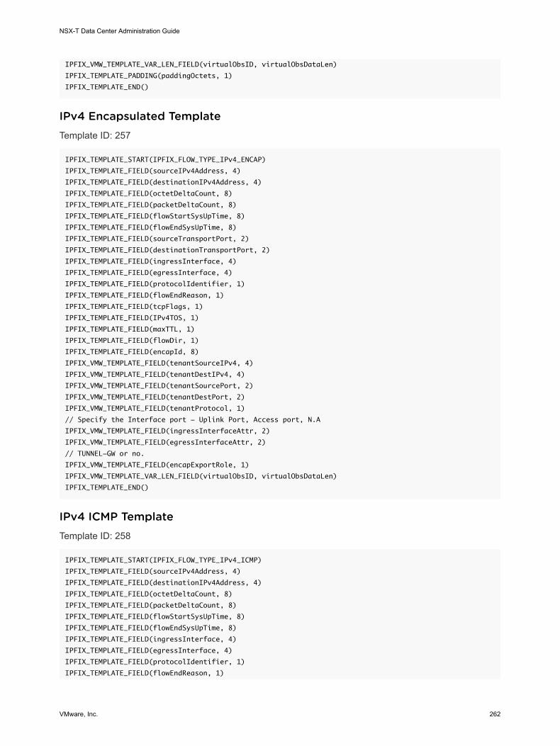
IPFIX_VMW_TEMPLATE_VAR_LEN_FIELD(virtualObsID, virtualObsDataLen)
IPFIX_TEMPLATE_PADDING(paddingOctets, 1)
IPFIX_TEMPLATE_END()
IPv4 Encapsulated TemplateTemplate ID: 257
IPFIX_TEMPLATE_START(IPFIX_FLOW_TYPE_IPv4_ENCAP)
IPFIX_TEMPLATE_FIELD(sourceIPv4Address, 4)
IPFIX_TEMPLATE_FIELD(destinationIPv4Address, 4)
IPFIX_TEMPLATE_FIELD(octetDeltaCount, 8)
IPFIX_TEMPLATE_FIELD(packetDeltaCount, 8)
IPFIX_TEMPLATE_FIELD(flowStartSysUpTime, 8)
IPFIX_TEMPLATE_FIELD(flowEndSysUpTime, 8)
IPFIX_TEMPLATE_FIELD(sourceTransportPort, 2)
IPFIX_TEMPLATE_FIELD(destinationTransportPort, 2)
IPFIX_TEMPLATE_FIELD(ingressInterface, 4)
IPFIX_TEMPLATE_FIELD(egressInterface, 4)
IPFIX_TEMPLATE_FIELD(protocolIdentifier, 1)
IPFIX_TEMPLATE_FIELD(flowEndReason, 1)
IPFIX_TEMPLATE_FIELD(tcpFlags, 1)
IPFIX_TEMPLATE_FIELD(IPv4TOS, 1)
IPFIX_TEMPLATE_FIELD(maxTTL, 1)
IPFIX_TEMPLATE_FIELD(flowDir, 1)
IPFIX_TEMPLATE_FIELD(encapId, 8)
IPFIX_VMW_TEMPLATE_FIELD(tenantSourceIPv4, 4)
IPFIX_VMW_TEMPLATE_FIELD(tenantDestIPv4, 4)
IPFIX_VMW_TEMPLATE_FIELD(tenantSourcePort, 2)
IPFIX_VMW_TEMPLATE_FIELD(tenantDestPort, 2)
IPFIX_VMW_TEMPLATE_FIELD(tenantProtocol, 1)
// Specify the Interface port - Uplink Port, Access port, N.A
IPFIX_VMW_TEMPLATE_FIELD(ingressInterfaceAttr, 2)
IPFIX_VMW_TEMPLATE_FIELD(egressInterfaceAttr, 2)
// TUNNEL-GW or no.
IPFIX_VMW_TEMPLATE_FIELD(encapExportRole, 1)
IPFIX_VMW_TEMPLATE_VAR_LEN_FIELD(virtualObsID, virtualObsDataLen)
IPFIX_TEMPLATE_END()
IPv4 ICMP TemplateTemplate ID: 258
IPFIX_TEMPLATE_START(IPFIX_FLOW_TYPE_IPv4_ICMP)
IPFIX_TEMPLATE_FIELD(sourceIPv4Address, 4)
IPFIX_TEMPLATE_FIELD(destinationIPv4Address, 4)
IPFIX_TEMPLATE_FIELD(octetDeltaCount, 8)
IPFIX_TEMPLATE_FIELD(packetDeltaCount, 8)
IPFIX_TEMPLATE_FIELD(flowStartSysUpTime, 8)
IPFIX_TEMPLATE_FIELD(flowEndSysUpTime, 8)
IPFIX_TEMPLATE_FIELD(ingressInterface, 4)
IPFIX_TEMPLATE_FIELD(egressInterface, 4)
IPFIX_TEMPLATE_FIELD(protocolIdentifier, 1)
IPFIX_TEMPLATE_FIELD(flowEndReason, 1)
NSX-T Data Center Administration Guide
VMware, Inc. 262

IPFIX_TEMPLATE_FIELD(IPv4TOS, 1)
IPFIX_TEMPLATE_FIELD(maxTTL, 1)
IPFIX_TEMPLATE_FIELD(flowDir, 1)
IPFIX_TEMPLATE_FIELD(encapId, 8)
// Specify the Interface port - Uplink Port, Access Port, or NA.
IPFIX_VMW_TEMPLATE_FIELD(ingressInterfaceAttr, 2)
IPFIX_VMW_TEMPLATE_FIELD(egressInterfaceAttr, 2)
IPFIX_VMW_TEMPLATE_FIELD(encapExportRole, 1)
IPFIX_VMW_TEMPLATE_VAR_LEN_FIELD(virtualObsID, virtualObsDataLen)
IPFIX_TEMPLATE_PADDING(paddingOctets, 2)
IPFIX_TEMPLATE_END()
IPv4 ICMP Encapsulated TemplateTemplate ID: 259
IPFIX_TEMPLATE_START(IPFIX_FLOW_TYPE_IPv4_ICMP_ENCAP)
IPFIX_TEMPLATE_FIELD(sourceIPv4Address, 4)
IPFIX_TEMPLATE_FIELD(destinationIPv4Address, 4)
IPFIX_TEMPLATE_FIELD(octetDeltaCount, 8)
IPFIX_TEMPLATE_FIELD(packetDeltaCount, 8)
IPFIX_TEMPLATE_FIELD(flowStartSysUpTime, 8)
IPFIX_TEMPLATE_FIELD(flowEndSysUpTime, 8)
IPFIX_TEMPLATE_FIELD(sourceTransportPort, 2)
IPFIX_TEMPLATE_FIELD(destinationTransportPort, 2)
IPFIX_TEMPLATE_FIELD(ingressInterface, 4)
IPFIX_TEMPLATE_FIELD(egressInterface, 4)
IPFIX_TEMPLATE_FIELD(protocolIdentifier, 1)
IPFIX_TEMPLATE_FIELD(flowEndReason, 1)
IPFIX_TEMPLATE_FIELD(IPv4TOS, 1)
IPFIX_TEMPLATE_FIELD(maxTTL, 1)
IPFIX_TEMPLATE_FIELD(flowDir, 1)
IPFIX_TEMPLATE_FIELD(encapId, 8)
IPFIX_VMW_TEMPLATE_FIELD(tenantSourceIPv4, 4)
IPFIX_VMW_TEMPLATE_FIELD(tenantDestIPv4, 4)
IPFIX_VMW_TEMPLATE_FIELD(tenantProtocol, 1)
// Specify the Interface port- Uplink Port, Access port,N.A
IPFIX_VMW_TEMPLATE_FIELD(ingressInterfaceAttr, 2)
IPFIX_VMW_TEMPLATE_FIELD(egressInterfaceAttr, 2)
// TUNNEL-GW or no.
IPFIX_VMW_TEMPLATE_FIELD(encapExportRole, 1)
IPFIX_VMW_TEMPLATE_VAR_LEN_FIELD(virtualObsID, virtualObsDataLen)
IPFIX_TEMPLATE_PADDING(paddingOctets, 1)
IPFIX_TEMPLATE_END()
IPv6 TemplateTemplate ID: 260
IPFIX_TEMPLATE_START(IPFIX_FLOW_TYPE_IPv6)
IPFIX_TEMPLATE_FIELD(sourceIPv6Address, 16)
IPFIX_TEMPLATE_FIELD(destinationIPv6Address, 16)
IPFIX_TEMPLATE_FIELD(octetDeltaCount, 8)
IPFIX_TEMPLATE_FIELD(packetDeltaCount, 8)
NSX-T Data Center Administration Guide
VMware, Inc. 263

IPFIX_TEMPLATE_FIELD(flowStartSysUpTime, 8)
IPFIX_TEMPLATE_FIELD(flowEndSysUpTime, 8)
IPFIX_TEMPLATE_FIELD(sourceTransportPort, 2)
IPFIX_TEMPLATE_FIELD(destinationTransportPort, 2)
IPFIX_TEMPLATE_FIELD(ingressInterface, 4)
IPFIX_TEMPLATE_FIELD(egressInterface, 4)
IPFIX_TEMPLATE_FIELD(encapId, 8)
IPFIX_TEMPLATE_FIELD(protocolIdentifier, 1)
IPFIX_TEMPLATE_FIELD(flowEndReason, 1)
IPFIX_TEMPLATE_FIELD(tcpFlags, 1)
IPFIX_TEMPLATE_FIELD(IPv6TOS,1)
IPFIX_TEMPLATE_FIELD(maxTTL, 1)
IPFIX_TEMPLATE_FIELD(flowDir, 1)
// Specify the Interface port - Uplink Port, Access Port, or NA.
IPFIX_VMW_TEMPLATE_FIELD(ingressInterfaceAttr, 2)
IPFIX_VMW_TEMPLATE_FIELD(egressInterfaceAttr, 2)
IPFIX_VMW_TEMPLATE_FIELD(encapExportRole, 1)
IPFIX_VMW_TEMPLATE_VAR_LEN_FIELD(virtualObsID, virtualObsDataLen)
IPFIX_TEMPLATE_PADDING(paddingOctets, 1)
IPFIX_TEMPLATE_END()
IPv6 Encapsulated TemplateTemplate ID: 261
IPFIX_TEMPLATE_START(IPFIX_FLOW_TYPE_IPv6_ENCAP)
IPFIX_TEMPLATE_FIELD(sourceIPv4Address, 4)
IPFIX_TEMPLATE_FIELD(destinationIPv4Address, 4)
IPFIX_TEMPLATE_FIELD(octetDeltaCount, 8)
IPFIX_TEMPLATE_FIELD(packetDeltaCount, 8)
IPFIX_TEMPLATE_FIELD(flowStartSysUpTime, 8)
IPFIX_TEMPLATE_FIELD(flowEndSysUpTime, 8)
IPFIX_TEMPLATE_FIELD(sourceTransportPort, 2)
IPFIX_TEMPLATE_FIELD(destinationTransportPort, 2)
IPFIX_TEMPLATE_FIELD(ingressInterface, 4)
IPFIX_TEMPLATE_FIELD(egressInterface, 4)
IPFIX_TEMPLATE_FIELD(protocolIdentifier, 1)
IPFIX_TEMPLATE_FIELD(flowEndReason, 1)
IPFIX_TEMPLATE_FIELD(tcpFlags, 1)
IPFIX_TEMPLATE_FIELD(IPv6TOS, 1)
IPFIX_TEMPLATE_FIELD(maxTTL, 1)
IPFIX_TEMPLATE_FIELD(flowDir, 1)
//ENCAP specific
IPFIX_TEMPLATE_FIELD(encapId, 8)
IPFIX_VMW_TEMPLATE_FIELD(tenantSourceIPv6, 16)
IPFIX_VMW_TEMPLATE_FIELD(tenantDestIPv6, 16)
IPFIX_VMW_TEMPLATE_FIELD(tenantSourcePort, 2)
IPFIX_VMW_TEMPLATE_FIELD(tenantDestPort, 2)
IPFIX_VMW_TEMPLATE_FIELD(tenantProtocol, 1)
// Specify the Interface port - Uplink Port, Access Port, or NA
IPFIX_VMW_TEMPLATE_FIELD(ingressInterfaceAttr, 2)
IPFIX_VMW_TEMPLATE_FIELD(egressInterfaceAttr, 2)
NSX-T Data Center Administration Guide
VMware, Inc. 264

// TUNNEL-GW or no.
IPFIX_VMW_TEMPLATE_FIELD(encapExportRole, 1)
IPFIX_VMW_TEMPLATE_VAR_LEN_FIELD(virtualObsID, virtualObsDataLen)
IPFIX_TEMPLATE_END()
IPv6 ICMP TemplateTemplate ID: 262
IPFIX_TEMPLATE_START(IPFIX_FLOW_TYPE_IPv6_ICMP)
IPFIX_TEMPLATE_FIELD(sourceIPv6Address, 16)
IPFIX_TEMPLATE_FIELD(destinationIPv6Address, 16)
IPFIX_TEMPLATE_FIELD(octetDeltaCount, 8)
IPFIX_TEMPLATE_FIELD(packetDeltaCount, 8)
IPFIX_TEMPLATE_FIELD(flowStartSysUpTime, 8)
IPFIX_TEMPLATE_FIELD(flowEndSysUpTime, 8)
IPFIX_TEMPLATE_FIELD(ingressInterface, 4)
IPFIX_TEMPLATE_FIELD(egressInterface, 4)
IPFIX_TEMPLATE_FIELD(protocolIdentifier, 1)
IPFIX_TEMPLATE_FIELD(flowEndReason, 1)
IPFIX_TEMPLATE_FIELD(IPv6TOS, 1)
IPFIX_TEMPLATE_FIELD(maxTTL, 1)
IPFIX_TEMPLATE_FIELD(flowDir, 1)
IPFIX_TEMPLATE_FIELD(encapId, 8)
// Specify the Interface port - Uplink Port, Access Port, or NA.
IPFIX_VMW_TEMPLATE_FIELD(ingressInterfaceAttr, 2)
IPFIX_VMW_TEMPLATE_FIELD(egressInterfaceAttr, 2)
IPFIX_VMW_TEMPLATE_FIELD(encapExportRole, 1)
IPFIX_VMW_TEMPLATE_VAR_LEN_FIELD(virtualObsID, virtualObsDataLen)
IPFIX_TEMPLATE_PADDING(paddingOctets, 2)
IPFIX_TEMPLATE_END()
IPv6 ICMP Encapsulated TemplateTemplate ID: 263
IPFIX_TEMPLATE_START(IPFIX_FLOW_TYPE_IPv6_ICMP_ENCAP)
IPFIX_TEMPLATE_FIELD(sourceIPv4Address, 4)
IPFIX_TEMPLATE_FIELD(destinationIPv4Address, 4)
IPFIX_TEMPLATE_FIELD(octetDeltaCount, 8)
IPFIX_TEMPLATE_FIELD(packetDeltaCount, 8)
IPFIX_TEMPLATE_FIELD(flowStartSysUpTime, 8)
IPFIX_TEMPLATE_FIELD(flowEndSysUpTime, 8)
IPFIX_VMW_TEMPLATE_FIELD(sourceTransportPort, 2)
IPFIX_VMW_TEMPLATE_FIELD(destinationTransportPort, 2)
IPFIX_TEMPLATE_FIELD(ingressInterface, 4)
IPFIX_TEMPLATE_FIELD(egressInterface, 4)
IPFIX_TEMPLATE_FIELD(protocolIdentifier, 1)
IPFIX_TEMPLATE_FIELD(IPv6TOS, 1)
IPFIX_TEMPLATE_FIELD(maxTTL, 1)
IPFIX_TEMPLATE_FIELD(flowDir, 1)
IPFIX_TEMPLATE_FIELD(flowEndReason, 1)
//ENCAP Specific
IPFIX_TEMPLATE_FIELD(encapId, 8)
NSX-T Data Center Administration Guide
VMware, Inc. 265

IPFIX_VMW_TEMPLATE_FIELD(tenantSourceIPv6, 16)
IPFIX_VMW_TEMPLATE_FIELD(tenantDestIPv6, 16)
IPFIX_VMW_TEMPLATE_FIELD(tenantProtocol, 1)
// Specify the Interface port - Uplink Port, Access Port, or NA
IPFIX_VMW_TEMPLATE_FIELD(ingressInterfaceAttr, 2)
IPFIX_VMW_TEMPLATE_FIELD(egressInterfaceAttr, 2)
// TUNNEL-GW or no.
IPFIX_VMW_TEMPLATE_FIELD(encapExportRole, 1)
IPFIX_VMW_TEMPLATE_VAR_LEN_FIELD(virtualObsID, virtualObsDataLen)
IPFIX_TEMPLATE_PADDING(paddingOctets, 1)
IPFIX_TEMPLATE_END()
KVM IPFIX TemplatesA KVM host transport node supports 88 IPFIX flow templates and one options template.
KVM Ethernet IPFIX TemplatesThere are four KVM Ethernet IPFIX templates: ingress, egress, ingress with tunnel, and egress with tunnel.
Ethernet Ingress
Template ID: 256. Field count: 27.
The fields are:
n observationPointId (length: 4)
n DIRECTION (length: 1)
n SRC_MAC (length: 6)
n DESTINATION_MAC (length: 6)
n ethernetType (length: 2)
n ethernetHeaderLength (length: 1)
n INPUT_SNMP (length: 4)
n Unknown(368) (length: 4)
n IF_NAME (length: variable)
n IF_DESC (length: variable)
n 898 (length: variable, PEN: VMware Inc. (6876))
n flowStartDeltaMicroseconds (length: 4)
n flowEndDeltaMicroseconds (length: 4)
n DROPPED_PACKETS (length: 8)
n DROPPED_PACKETS_TOTAL (length: 8)
n PKTS (length: 8)
NSX-T Data Center Administration Guide
VMware, Inc. 266

n PACKETS_TOTAL (length: 8)
n Unknown(354) (length: 8)
n Unknown(355) (length: 8)
n Unknown(356) (length: 8)
n Unknown(357) (length: 8)
n Unknown(358) (length: 8)
n MUL_DPKTS (length: 8)
n postMCastPacketTotalCount (length: 8)
n Unknown(352) (length: 8)
n Unknown(353) (length: 8)
n flowEndReason (length: 1)
Ethernet Egress
Template ID: 257. Field count: 31.
The fields are:
n observationPointId (length: 4)
n DIRECTION (length: 1)
n SRC_MAC (length: 6)
n DESTINATION_MAC (length: 6)
n ethernetType (length: 2)
n ethernetHeaderLength (length: 1)
n INPUT_SNMP (length: 4)
n Unknown(368) (length: 4)
n IF_NAME (length: variable)
n IF_DESC (length: variable)
n OUTPUT_SNMP (length: 4)
n Unknown(369) (length: 8)
n IF_NAME (length: variable)
n IF_DESC (length: variable)
n 898 (length: variable, PEN: VMware Inc. (6876))
n flowStartDeltaMicroseconds (length: 4)
n flowEndDeltaMicroseconds (length: 4)
NSX-T Data Center Administration Guide
VMware, Inc. 267

n DROPPED_PACKETS (length: 8)
n DROPPED_PACKETS_TOTAL (length: 8)
n PKTS (length: 8)
n PACKETS_TOTAL (length: 8)
n Unknown(354) (length: 8)
n Unknown(355) (length: 8)
n Unknown(356) (length: 8)
n Unknown(357) (length: 8)
n Unknown(358) (length: 8)
n MUL_DPKTS (length: 8)
n postMCastPacketTotalCount (length: 8)
n Unknown(352) (length: 8)
n Unknown(353) (length: 8)
n flowEndReason (length: 1)
Ethernet Ingress with Tunnel
Template ID: 258. Field count: 34.
The fields are:
n observationPointId (length: 4)
n DIRECTION (length: 1)
n SRC_MAC (length: 6)
n DESTINATION_MAC (length: 6)
n ethernetType (length: 2)
n ethernetHeaderLength (length: 1)
n INPUT_SNMP (length: 4)
n Unknown(368) (length: 4)
n IF_NAME (length: variable)
n IF_DESC (length: variable)
n 893 (length: 4, PEN: VMware Inc. (6876))
n 894 (length: 4, PEN: VMware Inc. (6876))
n 895 (length: 1, PEN: VMware Inc. (6876))
n 896 (length: 2, PEN: VMware Inc. (6876))
NSX-T Data Center Administration Guide
VMware, Inc. 268

n 897 (length: 2, PEN: VMware Inc. (6876))
n 891 (length: 1, PEN: VMware Inc. (6876))
n 892 (length: variable, PEN: VMware Inc. (6876))
n 898 (length: variable, PEN: VMware Inc. (6876))
n flowStartDeltaMicroseconds (length: 4)
n flowEndDeltaMicroseconds (length: 4)
n DROPPED_PACKETS (length: 8)
n DROPPED_PACKETS_TOTAL (length: 8)
n PKTS (length: 8)
n PACKETS_TOTAL (length: 8)
n Unknown(354) (length: 8)
n Unknown(355) (length: 8)
n Unknown(356) (length: 8)
n Unknown(357) (length: 8)
n Unknown(358) (length: 8)
n MUL_DPKTS (length: 8)
n postMCastPacketTotalCount (length: 8)
n Unknown(352) (length: 8)
n Unknown(353) (length: 8)
n flowEndReason (length: 1)
Ethernet Egress with Tunnel
Template ID: 259. Field count: 38.
The fields are:
n observationPointId (length: 4)
n DIRECTION (length: 1)
n SRC_MAC (length: 6)
n DESTINATION_MAC (length: 6)
n ethernetType (length: 2)
n ethernetHeaderLength (length: 1)
n INPUT_SNMP (length: 4)
n Unknown(368) (length: 4)
NSX-T Data Center Administration Guide
VMware, Inc. 269

n IF_NAME (length: variable)
n IF_DESC (length: variable)
n OUTPUT_SNMP (length: 4)
n Unknown(369) (length: 8)
n IF_NAME (length: variable)
n IF_DESC (length: variable)
n 893 (length: 4, PEN: VMware Inc. (6876))
n 894 (length: 4, PEN: VMware Inc. (6876))
n 895 (length: 1, PEN: VMware Inc. (6876))
n 896 (length: 2, PEN: VMware Inc. (6876))
n 897 (length: 2, PEN: VMware Inc. (6876))
n 891 (length: 1, PEN: VMware Inc. (6876))
n 892 (length: variable, PEN: VMware Inc. (6876))
n 898 (length: variable, PEN: VMware Inc. (6876))
n flowStartDeltaMicroseconds (length: 4)
n flowEndDeltaMicroseconds (length: 4)
n DROPPED_PACKETS (length: 8)
n DROPPED_PACKETS_TOTAL (length: 8)
n PKTS (length: 8)
n PACKETS_TOTAL (length: 8)
n Unknown(354) (length: 8)
n Unknown(355) (length: 8)
n Unknown(356) (length: 8)
n Unknown(357) (length: 8)
n Unknown(358) (length: 8)
n MUL_DPKTS (length: 8)
n postMCastPacketTotalCount (length: 8)
n Unknown(352) (length: 8)
n Unknown(353) (length: 8)
n flowEndReason (length: 1)
NSX-T Data Center Administration Guide
VMware, Inc. 270

KVM IPv4 IPFIX TemplatesThere are four KVM IPv4 IPFIX templates: ingress, egress, ingress with tunnel, and egress with tunnel.
IPv4 Ingress
Template ID: 276. Field count: 45.
The fields are:
n observationPointId (length: 4)
n DIRECTION (length: 1)
n SRC_MAC (length: 6)
n DESTINATION_MAC (length: 6)
n ethernetType (length: 2)
n ethernetHeaderLength (length: 1)
n INPUT_SNMP (length: 4)
n Unknown(368) (length: 4)
n IF_NAME (length: variable)
n IF_DESC (length: variable)
n IP_PROTOCOL_VERSION (Length: 1)
n IP_TTL (Length: 1)
n PROTOCOL (Length: 1)
n IP_DSCP (Length: 1)
n IP_PRECEDENCE (Length: 1)
n IP_TOS (Length: 1)
n IP_SRC_ADDR (Length: 4)
n IP_DST_ADDR (Length: 4)
n 898 (length: variable, PEN: VMware Inc. (6876))
n flowStartDeltaMicroseconds (length: 4)
n flowEndDeltaMicroseconds (length: 4)
n DROPPED_PACKETS (length: 8)
n DROPPED_PACKETS_TOTAL (length: 8)
n PKTS (length: 8)
n PACKETS_TOTAL (length: 8)
n Unknown(354) (length: 8)
NSX-T Data Center Administration Guide
VMware, Inc. 271

n Unknown(355) (length: 8)
n Unknown(356) (length: 8)
n Unknown(357) (length: 8)
n Unknown(358) (length: 8)
n MUL_DPKTS (length: 8)
n postMCastPacketTotalCount (length: 8)
n Unknown(352) (length: 8)
n Unknown(353) (length: 8)
n flowEndReason (length: 1)
n DROPPED_BYTES (Length: 8)
n DROPPED_BYTES_TOTAL (Length: 8)
n BYTES (Length: 8)
n BYTES_TOTAL (Length: 8)
n BYTES_SQUARED (Length: 8)
n BYTES_SQUARED_PERMANENT (Length: 8)
n IP LENGTH MINIMUM (Length: 8)
n IP LENGTH MAXIMUM (Length: 8)
n MUL_DOCTETS (Length: 8)
n postMCastOctetTotalCount (Length: 8)
IPv4 Egress
Template ID: 277. Field count: 49.
The fields are:
n observationPointId (length: 4)
n DIRECTION (length: 1)
n SRC_MAC (length: 6)
n DESTINATION_MAC (length: 6)
n ethernetType (length: 2)
n ethernetHeaderLength (length: 1)
n INPUT_SNMP (length: 4)
n Unknown(368) (length: 4)
n IF_NAME (length: variable)
NSX-T Data Center Administration Guide
VMware, Inc. 272

n IF_DESC (length: variable)
n OUTPUT_SNMP (Length: 4)
n Unknown(369) (Length: 4)
n IF_NAME (Length: variable)
n IF_DESC (Length: variable)
n IP_PROTOCOL_VERSION (Length: 1)
n IP_TTL (Length: 1)
n PROTOCOL (Length: 1)
n IP_DSCP (Length: 1)
n IP_PRECEDENCE (Length: 1)
n IP_TOS (Length: 1)
n IP_SRC_ADDR (Length: 4)
n IP_DST_ADDR (Length: 4)
n 898 (length: variable, PEN: VMware Inc. (6876))
n flowStartDeltaMicroseconds (length: 4)
n flowEndDeltaMicroseconds (length: 4)
n DROPPED_PACKETS (length: 8)
n DROPPED_PACKETS_TOTAL (length: 8)
n PKTS (length: 8)
n PACKETS_TOTAL (length: 8)
n Unknown(354) (length: 8)
n Unknown(355) (length: 8)
n Unknown(356) (length: 8)
n Unknown(357) (length: 8)
n Unknown(358) (length: 8)
n MUL_DPKTS (length: 8)
n postMCastPacketTotalCount (length: 8)
n Unknown(352) (length: 8)
n Unknown(353) (length: 8)
n flowEndReason (length: 1)
n DROPPED_BYTES (Length: 8)
n DROPPED_BYTES_TOTAL (Length: 8)
NSX-T Data Center Administration Guide
VMware, Inc. 273

n BYTES (Length: 8)
n BYTES_TOTAL (Length: 8)
n BYTES_SQUARED (Length: 8)
n BYTES_SQUARED_PERMANENT (Length: 8)
n IP LENGTH MINIMUM (Length: 8)
n IP LENGTH MAXIMUM (Length: 8)
n MUL_DOCTETS (Length: 8)
n postMCastOctetTotalCount (Length: 8)
IPv4 Ingress with Tunnel
Template ID: 278. Field count: 52.
The fields are:
n observationPointId (length: 4)
n DIRECTION (length: 1)
n SRC_MAC (length: 6)
n DESTINATION_MAC (length: 6)
n ethernetType (length: 2)
n ethernetHeaderLength (length: 1)
n INPUT_SNMP (length: 4)
n Unknown(368) (length: 4)
n IF_NAME (length: variable)
n IF_DESC (length: variable)
n IP_PROTOCOL_VERSION (Length: 1)
n IP_TTL (Length: 1)
n PROTOCOL (Length: 1)
n IP_DSCP (Length: 1)
n IP_PRECEDENCE (Length: 1)
n IP_TOS (Length: 1)
n IP_SRC_ADDR (Length: 4)
n IP_DST_ADDR (Length: 4)
n 893 (length: 4, PEN: VMware Inc. (6876))
n 894 (length: 4, PEN: VMware Inc. (6876))
NSX-T Data Center Administration Guide
VMware, Inc. 274

n 895 (length: 1, PEN: VMware Inc. (6876))
n 896 (length: 2, PEN: VMware Inc. (6876))
n 897 (length: 2, PEN: VMware Inc. (6876))
n 891 (length: 1, PEN: VMware Inc. (6876))
n 892 (length: variable, PEN: VMware Inc. (6876))
n 898 (length: variable, PEN: VMware Inc. (6876))
n flowStartDeltaMicroseconds (length: 4)
n flowEndDeltaMicroseconds (length: 4)
n DROPPED_PACKETS (length: 8)
n DROPPED_PACKETS_TOTAL (length: 8)
n PKTS (length: 8)
n PACKETS_TOTAL (length: 8)
n Unknown(354) (length: 8)
n Unknown(355) (length: 8)
n Unknown(356) (length: 8)
n Unknown(357) (length: 8)
n Unknown(358) (length: 8)
n MUL_DPKTS (length: 8)
n postMCastPacketTotalCount (length: 8)
n Unknown(352) (length: 8)
n Unknown(353) (length: 8)
n flowEndReason (length: 1)
n DROPPED_BYTES (Length: 8)
n DROPPED_BYTES_TOTAL (Length: 8)
n BYTES (Length: 8)
n BYTES_TOTAL (Length: 8)
n BYTES_SQUARED (Length: 8)
n BYTES_SQUARED_PERMANENT (Length: 8)
n IP LENGTH MINIMUM (Length: 8)
n IP LENGTH MAXIMUM (Length: 8)
n MUL_DOCTETS (Length: 8)
n postMCastOctetTotalCount (Length: 8)
NSX-T Data Center Administration Guide
VMware, Inc. 275

IPv4 Egress with Tunnel
Template ID: 279. Field count: 56.
The fields are:
n observationPointId (length: 4)
n DIRECTION (length: 1)
n SRC_MAC (length: 6)
n DESTINATION_MAC (length: 6)
n ethernetType (length: 2)
n ethernetHeaderLength (length: 1)
n INPUT_SNMP (length: 4)
n Unknown(368) (length: 4)
n IF_NAME (length: variable)
n IF_DESC (length: variable)
n OUTPUT_SNMP (Length: 4)
n Unknown(369) (Length: 4)
n IF_NAME (Length: variable)
n IF_DESC (Length: variable)
n IP_PROTOCOL_VERSION (Length: 1)
n IP_TTL (Length: 1)
n PROTOCOL (Length: 1)
n IP_DSCP (Length: 1)
n IP_PRECEDENCE (Length: 1)
n IP_TOS (Length: 1)
n IP_SRC_ADDR (Length: 4)
n IP_DST_ADDR (Length: 4)
n 893 (length: 4, PEN: VMware Inc. (6876))
n 894 (length: 4, PEN: VMware Inc. (6876))
n 895 (length: 1, PEN: VMware Inc. (6876))
n 896 (length: 2, PEN: VMware Inc. (6876))
n 897 (length: 2, PEN: VMware Inc. (6876))
n 891 (length: 1, PEN: VMware Inc. (6876))
n 892 (length: variable, PEN: VMware Inc. (6876))
NSX-T Data Center Administration Guide
VMware, Inc. 276

n 898 (length: variable, PEN: VMware Inc. (6876))
n flowStartDeltaMicroseconds (length: 4)
n flowEndDeltaMicroseconds (length: 4)
n DROPPED_PACKETS (length: 8)
n DROPPED_PACKETS_TOTAL (length: 8)
n PKTS (length: 8)
n PACKETS_TOTAL (length: 8)
n Unknown(354) (length: 8)
n Unknown(355) (length: 8)
n Unknown(356) (length: 8)
n Unknown(357) (length: 8)
n Unknown(358) (length: 8)
n MUL_DPKTS (length: 8)
n postMCastPacketTotalCount (length: 8)
n Unknown(352) (length: 8)
n Unknown(353) (length: 8)
n flowEndReason (length: 1)
n DROPPED_BYTES (Length: 8)
n DROPPED_BYTES_TOTAL (Length: 8)
n BYTES (Length: 8)
n BYTES_TOTAL (Length: 8)
n BYTES_SQUARED (Length: 8)
n BYTES_SQUARED_PERMANENT (Length: 8)
n IP LENGTH MINIMUM (Length: 8)
n IP LENGTH MAXIMUM (Length: 8)
n MUL_DOCTETS (Length: 8)
n postMCastOctetTotalCount (Length: 8)
KVM TCP over IPv4 IPFIX TemplatesThere are four KVM TCP over IPv4 IPFIX templates: ingress, egress, ingress with tunnel, and egress with tunnel.
NSX-T Data Center Administration Guide
VMware, Inc. 277

TCP over IPv4 Ingress
Template ID: 280. Field count: 53.
The fields are:
n observationPointId (length: 4)
n DIRECTION (length: 1)
n SRC_MAC (length: 6)
n DESTINATION_MAC (length: 6)
n ethernetType (length: 2)
n ethernetHeaderLength (length: 1)
n INPUT_SNMP (length: 4)
n Unknown(368) (length: 4)
n IF_NAME (length: variable)
n IF_DESC (length: variable)
n IP_PROTOCOL_VERSION (Length: 1)
n IP_TTL (Length: 1)
n PROTOCOL (Length: 1)
n IP_DSCP (Length: 1)
n IP_PRECEDENCE (Length: 1)
n IP_TOS (Length: 1)
n IP_SRC_ADDR (Length: 4)
n IP_DST_ADDR (Length: 4)
n L4_SRC_PORT (Length: 2)
n L4_DST_PORT (Length: 2)
n 898 (length: variable, PEN: VMware Inc. (6876))
n flowStartDeltaMicroseconds (length: 4)
n flowEndDeltaMicroseconds (length: 4)
n DROPPED_PACKETS (length: 8)
n DROPPED_PACKETS_TOTAL (length: 8)
n PKTS (length: 8)
n PACKETS_TOTAL (length: 8)
n Unknown(354) (length: 8)
n Unknown(355) (length: 8)
NSX-T Data Center Administration Guide
VMware, Inc. 278

n Unknown(356) (length: 8)
n Unknown(357) (length: 8)
n Unknown(358) (length: 8)
n MUL_DPKTS (length: 8)
n postMCastPacketTotalCount (length: 8)
n Unknown(352) (length: 8)
n Unknown(353) (length: 8)
n flowEndReason (length: 1)
n DROPPED_BYTES (Length: 8)
n DROPPED_BYTES_TOTAL (Length: 8)
n BYTES (Length: 8)
n BYTES_TOTAL (Length: 8)
n BYTES_SQUARED (Length: 8)
n BYTES_SQUARED_PERMANENT (Length: 8)
n IP LENGTH MINIMUM (Length: 8)
n IP LENGTH MAXIMUM (Length: 8)
n MUL_DOCTETS (Length: 8)
n postMCastOctetTotalCount (Length: 8)
n tcpAckTotalCount (Length: 8)
n tcpFinTotalCount (Length: 8)
n tcpPshTotalCount (Length: 8)
n tcpRstTotalCount (Length: 8)
n tcpSynTotalCount (Length: 8)
n tcpUrgTotalCount (Length: 8)
TCP over IPv4 Egress
Template ID: 281. Field count: 57.
The fields are:
n observationPointId (length: 4)
n DIRECTION (length: 1)
n SRC_MAC (length: 6)
n DESTINATION_MAC (length: 6)
NSX-T Data Center Administration Guide
VMware, Inc. 279

n ethernetType (length: 2)
n ethernetHeaderLength (length: 1)
n INPUT_SNMP (length: 4)
n Unknown(368) (length: 4)
n IF_NAME (length: variable)
n IF_DESC (length: variable)
n OUTPUT_SNMP (Length: 4)
n Unknown(369) (Length: 4)
n IF_NAME (Length: variable)
n IF_DESC (Length: variable)
n IP_PROTOCOL_VERSION (Length: 1)
n IP_TTL (Length: 1)
n PROTOCOL (Length: 1)
n IP_DSCP (Length: 1)
n IP_PRECEDENCE (Length: 1)
n IP_TOS (Length: 1)
n IP_SRC_ADDR (Length: 4)
n IP_DST_ADDR (Length: 4)
n L4_SRC_PORT (Length: 2)
n L4_DST_PORT (Length: 2)
n 898 (length: variable, PEN: VMware Inc. (6876))
n flowStartDeltaMicroseconds (length: 4)
n flowEndDeltaMicroseconds (length: 4)
n DROPPED_PACKETS (length: 8)
n DROPPED_PACKETS_TOTAL (length: 8)
n PKTS (length: 8)
n PACKETS_TOTAL (length: 8)
n Unknown(354) (length: 8)
n Unknown(355) (length: 8)
n Unknown(356) (length: 8)
n Unknown(357) (length: 8)
n Unknown(358) (length: 8)
NSX-T Data Center Administration Guide
VMware, Inc. 280

n MUL_DPKTS (length: 8)
n postMCastPacketTotalCount (length: 8)
n Unknown(352) (length: 8)
n Unknown(353) (length: 8)
n flowEndReason (length: 1)
n DROPPED_BYTES (Length: 8)
n DROPPED_BYTES_TOTAL (Length: 8)
n BYTES (Length: 8)
n BYTES_TOTAL (Length: 8)
n BYTES_SQUARED (Length: 8)
n BYTES_SQUARED_PERMANENT (Length: 8)
n IP LENGTH MINIMUM (Length: 8)
n IP LENGTH MAXIMUM (Length: 8)
n MUL_DOCTETS (Length: 8)
n postMCastOctetTotalCount (Length: 8)
n tcpAckTotalCount (Length: 8)
n tcpFinTotalCount (Length: 8)
n tcpPshTotalCount (Length: 8)
n tcpRstTotalCount (Length: 8)
n tcpSynTotalCount (Length: 8)
n tcpUrgTotalCount (Length: 8)
TCP over IPv4 Ingress with Tunnel
Template ID: 282. Field count: 60.
The fields are:
n observationPointId (length: 4)
n DIRECTION (length: 1)
n SRC_MAC (length: 6)
n DESTINATION_MAC (length: 6)
n ethernetType (length: 2)
n ethernetHeaderLength (length: 1)
n INPUT_SNMP (length: 4)
NSX-T Data Center Administration Guide
VMware, Inc. 281

n Unknown(368) (length: 4)
n IF_NAME (length: variable)
n IF_DESC (length: variable)
n IP_PROTOCOL_VERSION (Length: 1)
n IP_TTL (Length: 1)
n PROTOCOL (Length: 1)
n IP_DSCP (Length: 1)
n IP_PRECEDENCE (Length: 1)
n IP_TOS (Length: 1)
n IP_SRC_ADDR (Length: 4)
n IP_DST_ADDR (Length: 4)
n L4_SRC_PORT (Length: 2)
n L4_DST_PORT (Length: 2)
n 893 (length: 4, PEN: VMware Inc. (6876))
n 894 (length: 4, PEN: VMware Inc. (6876))
n 895 (length: 1, PEN: VMware Inc. (6876))
n 896 (length: 2, PEN: VMware Inc. (6876))
n 897 (length: 2, PEN: VMware Inc. (6876))
n 891 (length: 1, PEN: VMware Inc. (6876))
n 892 (length: variable, PEN: VMware Inc. (6876))
n 898 (length: variable, PEN: VMware Inc. (6876))
n flowStartDeltaMicroseconds (length: 4)
n flowEndDeltaMicroseconds (length: 4)
n DROPPED_PACKETS (length: 8)
n DROPPED_PACKETS_TOTAL (length: 8)
n PKTS (length: 8)
n PACKETS_TOTAL (length: 8)
n Unknown(354) (length: 8)
n Unknown(355) (length: 8)
n Unknown(356) (length: 8)
n Unknown(357) (length: 8)
n Unknown(358) (length: 8)
NSX-T Data Center Administration Guide
VMware, Inc. 282
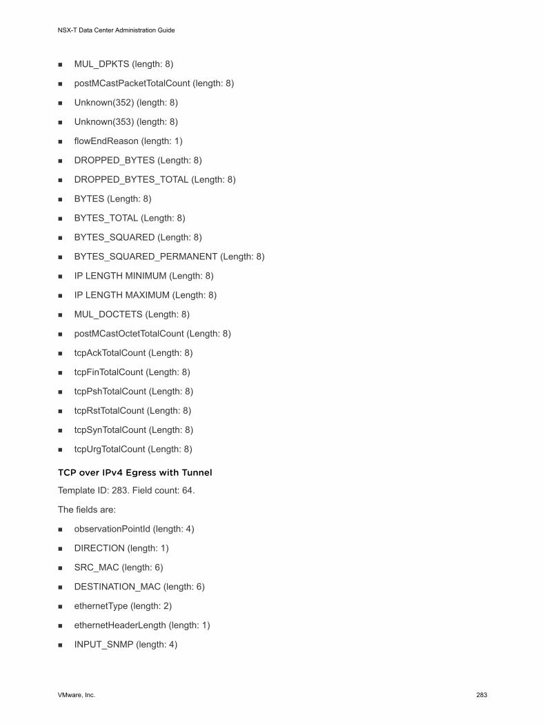
n MUL_DPKTS (length: 8)
n postMCastPacketTotalCount (length: 8)
n Unknown(352) (length: 8)
n Unknown(353) (length: 8)
n flowEndReason (length: 1)
n DROPPED_BYTES (Length: 8)
n DROPPED_BYTES_TOTAL (Length: 8)
n BYTES (Length: 8)
n BYTES_TOTAL (Length: 8)
n BYTES_SQUARED (Length: 8)
n BYTES_SQUARED_PERMANENT (Length: 8)
n IP LENGTH MINIMUM (Length: 8)
n IP LENGTH MAXIMUM (Length: 8)
n MUL_DOCTETS (Length: 8)
n postMCastOctetTotalCount (Length: 8)
n tcpAckTotalCount (Length: 8)
n tcpFinTotalCount (Length: 8)
n tcpPshTotalCount (Length: 8)
n tcpRstTotalCount (Length: 8)
n tcpSynTotalCount (Length: 8)
n tcpUrgTotalCount (Length: 8)
TCP over IPv4 Egress with Tunnel
Template ID: 283. Field count: 64.
The fields are:
n observationPointId (length: 4)
n DIRECTION (length: 1)
n SRC_MAC (length: 6)
n DESTINATION_MAC (length: 6)
n ethernetType (length: 2)
n ethernetHeaderLength (length: 1)
n INPUT_SNMP (length: 4)
NSX-T Data Center Administration Guide
VMware, Inc. 283

n Unknown(368) (length: 4)
n IF_NAME (length: variable)
n IF_DESC (length: variable)
n OUTPUT_SNMP (Length: 4)
n Unknown(369) (Length: 4)
n IF_NAME (Length: variable)
n IF_DESC (Length: variable)
n IP_PROTOCOL_VERSION (Length: 1)
n IP_TTL (Length: 1)
n PROTOCOL (Length: 1)
n IP_DSCP (Length: 1)
n IP_PRECEDENCE (Length: 1)
n IP_TOS (Length: 1)
n IP_SRC_ADDR (Length: 4)
n IP_DST_ADDR (Length: 4)
n L4_SRC_PORT (Length: 2)
n L4_DST_PORT (Length: 2)
n 893 (length: 4, PEN: VMware Inc. (6876))
n 894 (length: 4, PEN: VMware Inc. (6876))
n 895 (length: 1, PEN: VMware Inc. (6876))
n 896 (length: 2, PEN: VMware Inc. (6876))
n 897 (length: 2, PEN: VMware Inc. (6876))
n 891 (length: 1, PEN: VMware Inc. (6876))
n 892 (length: variable, PEN: VMware Inc. (6876))
n 898 (length: variable, PEN: VMware Inc. (6876))
n flowStartDeltaMicroseconds (length: 4)
n flowEndDeltaMicroseconds (length: 4)
n DROPPED_PACKETS (length: 8)
n DROPPED_PACKETS_TOTAL (length: 8)
n PKTS (length: 8)
n PACKETS_TOTAL (length: 8)
n Unknown(354) (length: 8)
NSX-T Data Center Administration Guide
VMware, Inc. 284
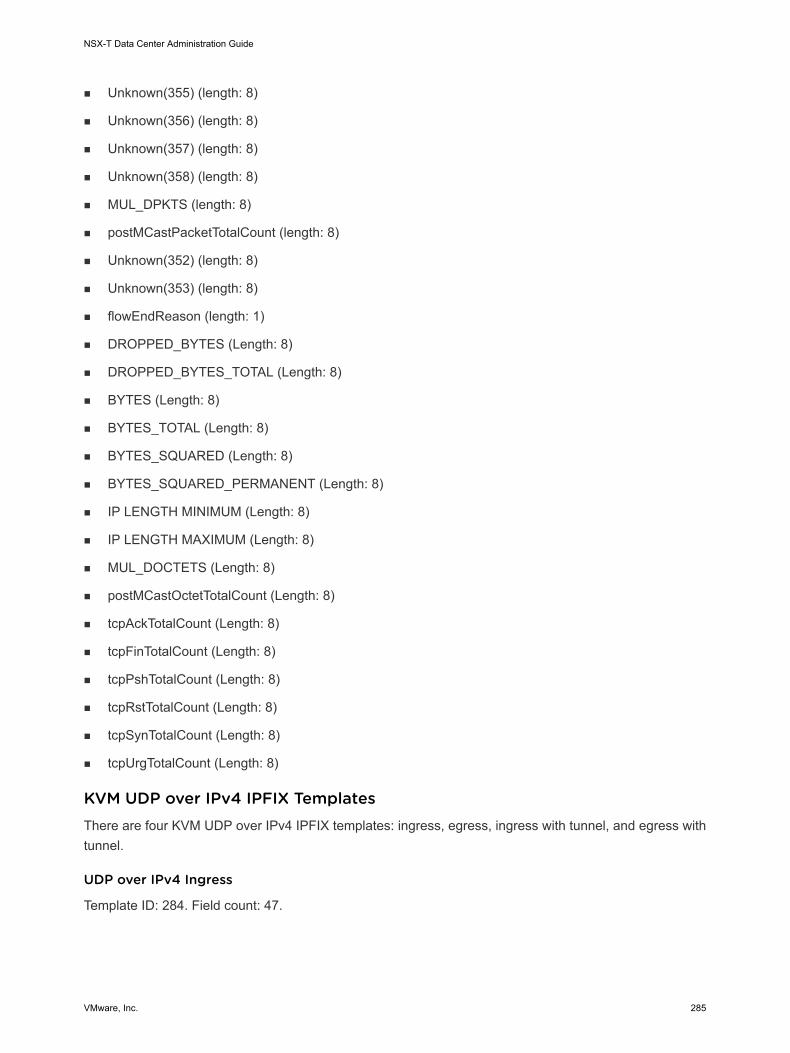
n Unknown(355) (length: 8)
n Unknown(356) (length: 8)
n Unknown(357) (length: 8)
n Unknown(358) (length: 8)
n MUL_DPKTS (length: 8)
n postMCastPacketTotalCount (length: 8)
n Unknown(352) (length: 8)
n Unknown(353) (length: 8)
n flowEndReason (length: 1)
n DROPPED_BYTES (Length: 8)
n DROPPED_BYTES_TOTAL (Length: 8)
n BYTES (Length: 8)
n BYTES_TOTAL (Length: 8)
n BYTES_SQUARED (Length: 8)
n BYTES_SQUARED_PERMANENT (Length: 8)
n IP LENGTH MINIMUM (Length: 8)
n IP LENGTH MAXIMUM (Length: 8)
n MUL_DOCTETS (Length: 8)
n postMCastOctetTotalCount (Length: 8)
n tcpAckTotalCount (Length: 8)
n tcpFinTotalCount (Length: 8)
n tcpPshTotalCount (Length: 8)
n tcpRstTotalCount (Length: 8)
n tcpSynTotalCount (Length: 8)
n tcpUrgTotalCount (Length: 8)
KVM UDP over IPv4 IPFIX TemplatesThere are four KVM UDP over IPv4 IPFIX templates: ingress, egress, ingress with tunnel, and egress with tunnel.
UDP over IPv4 Ingress
Template ID: 284. Field count: 47.
NSX-T Data Center Administration Guide
VMware, Inc. 285

The fields are:
n observationPointId (length: 4)
n DIRECTION (length: 1)
n SRC_MAC (length: 6)
n DESTINATION_MAC (length: 6)
n ethernetType (length: 2)
n ethernetHeaderLength (length: 1)
n INPUT_SNMP (length: 4)
n Unknown(368) (length: 4)
n IF_NAME (length: variable)
n IF_DESC (length: variable)
n IP_PROTOCOL_VERSION (Length: 1)
n IP_TTL (Length: 1)
n PROTOCOL (Length: 1)
n IP_DSCP (Length: 1)
n IP_PRECEDENCE (Length: 1)
n IP_TOS (Length: 1)
n IP_SRC_ADDR (Length: 4)
n IP_DST_ADDR (Length: 4)
n L4_SRC_PORT (Length: 2)
n L4_DST_PORT (Length: 2)
n 898 (length: variable, PEN: VMware Inc. (6876))
n flowStartDeltaMicroseconds (length: 4)
n flowEndDeltaMicroseconds (length: 4)
n DROPPED_PACKETS (length: 8)
n DROPPED_PACKETS_TOTAL (length: 8)
n PKTS (length: 8)
n PACKETS_TOTAL (length: 8)
n Unknown(354) (length: 8)
n Unknown(355) (length: 8)
n Unknown(356) (length: 8)
n Unknown(357) (length: 8)
NSX-T Data Center Administration Guide
VMware, Inc. 286

n Unknown(358) (length: 8)
n MUL_DPKTS (length: 8)
n postMCastPacketTotalCount (length: 8)
n Unknown(352) (length: 8)
n Unknown(353) (length: 8)
n flowEndReason (length: 1)
n DROPPED_BYTES (Length: 8)
n DROPPED_BYTES_TOTAL (Length: 8)
n BYTES (Length: 8)
n BYTES_TOTAL (Length: 8)
n BYTES_SQUARED (Length: 8)
n BYTES_SQUARED_PERMANENT (Length: 8)
n IP LENGTH MINIMUM (Length: 8)
n IP LENGTH MAXIMUM (Length: 8)
n MUL_DOCTETS (Length: 8)
n postMCastOctetTotalCount (Length: 8)
UDP over IPv4 Egress
Template ID: 285. Field count: 51.
The fields are:
n observationPointId (length: 4)
n DIRECTION (length: 1)
n SRC_MAC (length: 6)
n DESTINATION_MAC (length: 6)
n ethernetType (length: 2)
n ethernetHeaderLength (length: 1)
n INPUT_SNMP (length: 4)
n Unknown(368) (length: 4)
n IF_NAME (length: variable)
n IF_DESC (length: variable)
n OUTPUT_SNMP (Length: 4)
n Unknown(369) (Length: 4)
NSX-T Data Center Administration Guide
VMware, Inc. 287

n IF_NAME (Length: variable)
n IF_DESC (Length: variable)
n IP_PROTOCOL_VERSION (Length: 1)
n IP_TTL (Length: 1)
n PROTOCOL (Length: 1)
n IP_DSCP (Length: 1)
n IP_PRECEDENCE (Length: 1)
n IP_TOS (Length: 1)
n IP_SRC_ADDR (Length: 4)
n IP_DST_ADDR (Length: 4)
n L4_SRC_PORT (Length: 2)
n L4_DST_PORT (Length: 2)
n 898 (length: variable, PEN: VMware Inc. (6876))
n flowStartDeltaMicroseconds (length: 4)
n flowEndDeltaMicroseconds (length: 4)
n DROPPED_PACKETS (length: 8)
n DROPPED_PACKETS_TOTAL (length: 8)
n PKTS (length: 8)
n PACKETS_TOTAL (length: 8)
n Unknown(354) (length: 8)
n Unknown(355) (length: 8)
n Unknown(356) (length: 8)
n Unknown(357) (length: 8)
n Unknown(358) (length: 8)
n MUL_DPKTS (length: 8)
n postMCastPacketTotalCount (length: 8)
n Unknown(352) (length: 8)
n Unknown(353) (length: 8)
n flowEndReason (length: 1)
n DROPPED_BYTES (Length: 8)
n DROPPED_BYTES_TOTAL (Length: 8)
n BYTES (Length: 8)
NSX-T Data Center Administration Guide
VMware, Inc. 288

n BYTES_TOTAL (Length: 8)
n BYTES_SQUARED (Length: 8)
n BYTES_SQUARED_PERMANENT (Length: 8)
n IP LENGTH MINIMUM (Length: 8)
n IP LENGTH MAXIMUM (Length: 8)
n MUL_DOCTETS (Length: 8)
n postMCastOctetTotalCount (Length: 8)
UDP over IPv4 Ingress with Tunnel
Template ID: 286. Field count: 54.
The fields are:
n observationPointId (length: 4)
n DIRECTION (length: 1)
n SRC_MAC (length: 6)
n DESTINATION_MAC (length: 6)
n ethernetType (length: 2)
n ethernetHeaderLength (length: 1)
n INPUT_SNMP (length: 4)
n Unknown(368) (length: 4)
n IF_NAME (length: variable)
n IF_DESC (length: variable)
n IP_PROTOCOL_VERSION (Length: 1)
n IP_TTL (Length: 1)
n PROTOCOL (Length: 1)
n IP_DSCP (Length: 1)
n IP_PRECEDENCE (Length: 1)
n IP_TOS (Length: 1)
n IP_SRC_ADDR (Length: 4)
n IP_DST_ADDR (Length: 4)
n L4_SRC_PORT (Length: 2)
n L4_DST_PORT (Length: 2)
n 893 (length: 4, PEN: VMware Inc. (6876))
NSX-T Data Center Administration Guide
VMware, Inc. 289

n 894 (length: 4, PEN: VMware Inc. (6876))
n 895 (length: 1, PEN: VMware Inc. (6876))
n 896 (length: 2, PEN: VMware Inc. (6876))
n 897 (length: 2, PEN: VMware Inc. (6876))
n 891 (length: 1, PEN: VMware Inc. (6876))
n 892 (length: variable, PEN: VMware Inc. (6876))
n 898 (length: variable, PEN: VMware Inc. (6876))
n flowStartDeltaMicroseconds (length: 4)
n flowEndDeltaMicroseconds (length: 4)
n DROPPED_PACKETS (length: 8)
n DROPPED_PACKETS_TOTAL (length: 8)
n PKTS (length: 8)
n PACKETS_TOTAL (length: 8)
n Unknown(354) (length: 8)
n Unknown(355) (length: 8)
n Unknown(356) (length: 8)
n Unknown(357) (length: 8)
n Unknown(358) (length: 8)
n MUL_DPKTS (length: 8)
n postMCastPacketTotalCount (length: 8)
n Unknown(352) (length: 8)
n Unknown(353) (length: 8)
n flowEndReason (length: 1)
n DROPPED_BYTES (Length: 8)
n DROPPED_BYTES_TOTAL (Length: 8)
n BYTES (Length: 8)
n BYTES_TOTAL (Length: 8)
n BYTES_SQUARED (Length: 8)
n BYTES_SQUARED_PERMANENT (Length: 8)
n IP LENGTH MINIMUM (Length: 8)
n IP LENGTH MAXIMUM (Length: 8)
n MUL_DOCTETS (Length: 8)
NSX-T Data Center Administration Guide
VMware, Inc. 290

n postMCastOctetTotalCount (Length: 8)
UDP over IPv4 Egress with Tunnel
Template ID: 287. Field count: 58.
The fields are:
n observationPointId (length: 4)
n DIRECTION (length: 1)
n SRC_MAC (length: 6)
n DESTINATION_MAC (length: 6)
n ethernetType (length: 2)
n ethernetHeaderLength (length: 1)
n INPUT_SNMP (length: 4)
n Unknown(368) (length: 4)
n IF_NAME (length: variable)
n IF_DESC (length: variable)
n OUTPUT_SNMP (Length: 4)
n Unknown(369) (Length: 4)
n IF_NAME (Length: variable)
n IF_DESC (Length: variable)
n IP_PROTOCOL_VERSION (Length: 1)
n IP_TTL (Length: 1)
n PROTOCOL (Length: 1)
n IP_DSCP (Length: 1)
n IP_PRECEDENCE (Length: 1)
n IP_TOS (Length: 1)
n IP_SRC_ADDR (Length: 4)
n IP_DST_ADDR (Length: 4)
n L4_SRC_PORT (Length: 2)
n L4_DST_PORT (Length: 2)
n 893 (length: 4, PEN: VMware Inc. (6876))
n 894 (length: 4, PEN: VMware Inc. (6876))
n 895 (length: 1, PEN: VMware Inc. (6876))
NSX-T Data Center Administration Guide
VMware, Inc. 291

n 896 (length: 2, PEN: VMware Inc. (6876))
n 897 (length: 2, PEN: VMware Inc. (6876))
n 891 (length: 1, PEN: VMware Inc. (6876))
n 892 (length: variable, PEN: VMware Inc. (6876))
n 898 (length: variable, PEN: VMware Inc. (6876))
n flowStartDeltaMicroseconds (length: 4)
n flowEndDeltaMicroseconds (length: 4)
n DROPPED_PACKETS (length: 8)
n DROPPED_PACKETS_TOTAL (length: 8)
n PKTS (length: 8)
n PACKETS_TOTAL (length: 8)
n Unknown(354) (length: 8)
n Unknown(355) (length: 8)
n Unknown(356) (length: 8)
n Unknown(357) (length: 8)
n Unknown(358) (length: 8)
n MUL_DPKTS (length: 8)
n postMCastPacketTotalCount (length: 8)
n Unknown(352) (length: 8)
n Unknown(353) (length: 8)
n flowEndReason (length: 1)
n DROPPED_BYTES (Length: 8)
n DROPPED_BYTES_TOTAL (Length: 8)
n BYTES (Length: 8)
n BYTES_TOTAL (Length: 8)
n BYTES_SQUARED (Length: 8)
n BYTES_SQUARED_PERMANENT (Length: 8)
n IP LENGTH MINIMUM (Length: 8)
n IP LENGTH MAXIMUM (Length: 8)
n MUL_DOCTETS (Length: 8)
n postMCastOctetTotalCount (Length: 8)
NSX-T Data Center Administration Guide
VMware, Inc. 292

KVM SCTP over IPv4 IPFIX TemplatesThere are four KVM SCTP over IPv4 IPFIX templates: ingress, egress, ingress with tunnel, and egress with tunnel.
SCTP over IPv4 Ingress
Template ID: 288. Field count: 47.
The fields are:
n observationPointId (length: 4)
n DIRECTION (length: 1)
n SRC_MAC (length: 6)
n DESTINATION_MAC (length: 6)
n ethernetType (length: 2)
n ethernetHeaderLength (length: 1)
n INPUT_SNMP (length: 4)
n Unknown(368) (length: 4)
n IF_NAME (length: variable)
n IF_DESC (length: variable)
n IP_PROTOCOL_VERSION (Length: 1)
n IP_TTL (Length: 1)
n PROTOCOL (Length: 1)
n IP_DSCP (Length: 1)
n IP_PRECEDENCE (Length: 1)
n IP_TOS (Length: 1)
n IP_SRC_ADDR (Length: 4)
n IP_DST_ADDR (Length: 4)
n L4_SRC_PORT (Length: 2)
n L4_DST_PORT (Length: 2)
n 898 (length: variable, PEN: VMware Inc. (6876))
n flowStartDeltaMicroseconds (length: 4)
n flowEndDeltaMicroseconds (length: 4)
n DROPPED_PACKETS (length: 8)
n DROPPED_PACKETS_TOTAL (length: 8)
n PKTS (length: 8)
NSX-T Data Center Administration Guide
VMware, Inc. 293

n PACKETS_TOTAL (length: 8)
n Unknown(354) (length: 8)
n Unknown(355) (length: 8)
n Unknown(356) (length: 8)
n Unknown(357) (length: 8)
n Unknown(358) (length: 8)
n MUL_DPKTS (length: 8)
n postMCastPacketTotalCount (length: 8)
n Unknown(352) (length: 8)
n Unknown(353) (length: 8)
n flowEndReason (length: 1)
n DROPPED_BYTES (Length: 8)
n DROPPED_BYTES_TOTAL (Length: 8)
n BYTES (Length: 8)
n BYTES_TOTAL (Length: 8)
n BYTES_SQUARED (Length: 8)
n BYTES_SQUARED_PERMANENT (Length: 8)
n IP LENGTH MINIMUM (Length: 8)
n IP LENGTH MAXIMUM (Length: 8)
n MUL_DOCTETS (Length: 8)
n postMCastOctetTotalCount (Length: 8)
SCTP over IPv4 Egress
Template ID: 289. Field count: 51.
The fields are:
n observationPointId (length: 4)
n DIRECTION (length: 1)
n SRC_MAC (length: 6)
n DESTINATION_MAC (length: 6)
n ethernetType (length: 2)
n ethernetHeaderLength (length: 1)
n INPUT_SNMP (length: 4)
NSX-T Data Center Administration Guide
VMware, Inc. 294

n Unknown(368) (length: 4)
n IF_NAME (length: variable)
n IF_DESC (length: variable)
n OUTPUT_SNMP (Length: 4)
n Unknown(369) (Length: 4)
n IF_NAME (Length: variable)
n IF_DESC (Length: variable)
n IP_PROTOCOL_VERSION (Length: 1)
n IP_TTL (Length: 1)
n PROTOCOL (Length: 1)
n IP_DSCP (Length: 1)
n IP_PRECEDENCE (Length: 1)
n IP_TOS (Length: 1)
n IP_SRC_ADDR (Length: 4)
n IP_DST_ADDR (Length: 4)
n L4_SRC_PORT (Length: 2)
n L4_DST_PORT (Length: 2)
n 898 (length: variable, PEN: VMware Inc. (6876))
n flowStartDeltaMicroseconds (length: 4)
n flowEndDeltaMicroseconds (length: 4)
n DROPPED_PACKETS (length: 8)
n DROPPED_PACKETS_TOTAL (length: 8)
n PKTS (length: 8)
n PACKETS_TOTAL (length: 8)
n Unknown(354) (length: 8)
n Unknown(355) (length: 8)
n Unknown(356) (length: 8)
n Unknown(357) (length: 8)
n Unknown(358) (length: 8)
n MUL_DPKTS (length: 8)
n postMCastPacketTotalCount (length: 8)
n Unknown(352) (length: 8)
NSX-T Data Center Administration Guide
VMware, Inc. 295

n Unknown(353) (length: 8)
n flowEndReason (length: 1)
n DROPPED_BYTES (Length: 8)
n DROPPED_BYTES_TOTAL (Length: 8)
n BYTES (Length: 8)
n BYTES_TOTAL (Length: 8)
n BYTES_SQUARED (Length: 8)
n BYTES_SQUARED_PERMANENT (Length: 8)
n IP LENGTH MINIMUM (Length: 8)
n IP LENGTH MAXIMUM (Length: 8)
n MUL_DOCTETS (Length: 8)
n postMCastOctetTotalCount (Length: 8)
SCTP over IPv4 Ingress with Tunnel
Template ID: 290. Field count: 54.
The fields are:
n observationPointId (length: 4)
n DIRECTION (length: 1)
n SRC_MAC (length: 6)
n DESTINATION_MAC (length: 6)
n ethernetType (length: 2)
n ethernetHeaderLength (length: 1)
n INPUT_SNMP (length: 4)
n Unknown(368) (length: 4)
n IF_NAME (length: variable)
n IF_DESC (length: variable)
n IP_PROTOCOL_VERSION (Length: 1)
n IP_TTL (Length: 1)
n PROTOCOL (Length: 1)
n IP_DSCP (Length: 1)
n IP_PRECEDENCE (Length: 1)
n IP_TOS (Length: 1)
NSX-T Data Center Administration Guide
VMware, Inc. 296
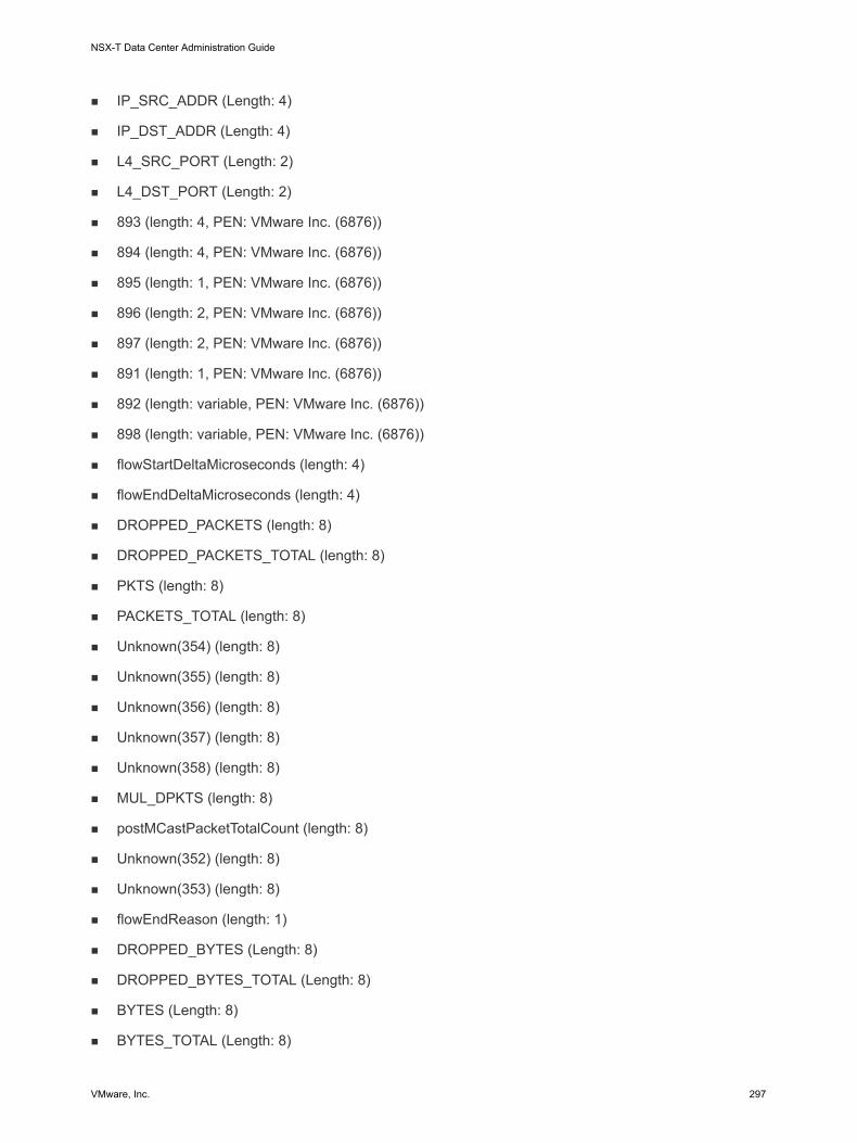
n IP_SRC_ADDR (Length: 4)
n IP_DST_ADDR (Length: 4)
n L4_SRC_PORT (Length: 2)
n L4_DST_PORT (Length: 2)
n 893 (length: 4, PEN: VMware Inc. (6876))
n 894 (length: 4, PEN: VMware Inc. (6876))
n 895 (length: 1, PEN: VMware Inc. (6876))
n 896 (length: 2, PEN: VMware Inc. (6876))
n 897 (length: 2, PEN: VMware Inc. (6876))
n 891 (length: 1, PEN: VMware Inc. (6876))
n 892 (length: variable, PEN: VMware Inc. (6876))
n 898 (length: variable, PEN: VMware Inc. (6876))
n flowStartDeltaMicroseconds (length: 4)
n flowEndDeltaMicroseconds (length: 4)
n DROPPED_PACKETS (length: 8)
n DROPPED_PACKETS_TOTAL (length: 8)
n PKTS (length: 8)
n PACKETS_TOTAL (length: 8)
n Unknown(354) (length: 8)
n Unknown(355) (length: 8)
n Unknown(356) (length: 8)
n Unknown(357) (length: 8)
n Unknown(358) (length: 8)
n MUL_DPKTS (length: 8)
n postMCastPacketTotalCount (length: 8)
n Unknown(352) (length: 8)
n Unknown(353) (length: 8)
n flowEndReason (length: 1)
n DROPPED_BYTES (Length: 8)
n DROPPED_BYTES_TOTAL (Length: 8)
n BYTES (Length: 8)
n BYTES_TOTAL (Length: 8)
NSX-T Data Center Administration Guide
VMware, Inc. 297

n BYTES_SQUARED (Length: 8)
n BYTES_SQUARED_PERMANENT (Length: 8)
n IP LENGTH MINIMUM (Length: 8)
n IP LENGTH MAXIMUM (Length: 8)
n MUL_DOCTETS (Length: 8)
n postMCastOctetTotalCount (Length: 8)
SCTP over IPv4 Egress with Tunnel
Template ID: 291. Field count: 58.
The fields are:
n observationPointId (length: 4)
n DIRECTION (length: 1)
n SRC_MAC (length: 6)
n DESTINATION_MAC (length: 6)
n ethernetType (length: 2)
n ethernetHeaderLength (length: 1)
n INPUT_SNMP (length: 4)
n Unknown(368) (length: 4)
n IF_NAME (length: variable)
n IF_DESC (length: variable)
n OUTPUT_SNMP (Length: 4)
n Unknown(369) (Length: 4)
n IF_NAME (Length: variable)
n IF_DESC (Length: variable)
n IP_PROTOCOL_VERSION (Length: 1)
n IP_TTL (Length: 1)
n PROTOCOL (Length: 1)
n IP_DSCP (Length: 1)
n IP_PRECEDENCE (Length: 1)
n IP_TOS (Length: 1)
n IP_SRC_ADDR (Length: 4)
n IP_DST_ADDR (Length: 4)
NSX-T Data Center Administration Guide
VMware, Inc. 298

n L4_SRC_PORT (Length: 2)
n L4_DST_PORT (Length: 2)
n 893 (length: 4, PEN: VMware Inc. (6876))
n 894 (length: 4, PEN: VMware Inc. (6876))
n 895 (length: 1, PEN: VMware Inc. (6876))
n 896 (length: 2, PEN: VMware Inc. (6876))
n 897 (length: 2, PEN: VMware Inc. (6876))
n 891 (length: 1, PEN: VMware Inc. (6876))
n 892 (length: variable, PEN: VMware Inc. (6876))
n 898 (length: variable, PEN: VMware Inc. (6876))
n flowStartDeltaMicroseconds (length: 4)
n flowEndDeltaMicroseconds (length: 4)
n DROPPED_PACKETS (length: 8)
n DROPPED_PACKETS_TOTAL (length: 8)
n PKTS (length: 8)
n PACKETS_TOTAL (length: 8)
n Unknown(354) (length: 8)
n Unknown(355) (length: 8)
n Unknown(356) (length: 8)
n Unknown(357) (length: 8)
n Unknown(358) (length: 8)
n MUL_DPKTS (length: 8)
n postMCastPacketTotalCount (length: 8)
n Unknown(352) (length: 8)
n Unknown(353) (length: 8)
n flowEndReason (length: 1)
n DROPPED_BYTES (Length: 8)
n DROPPED_BYTES_TOTAL (Length: 8)
n BYTES (Length: 8)
n BYTES_TOTAL (Length: 8)
n BYTES_SQUARED (Length: 8)
n BYTES_SQUARED_PERMANENT (Length: 8)
NSX-T Data Center Administration Guide
VMware, Inc. 299

n IP LENGTH MINIMUM (Length: 8)
n IP LENGTH MAXIMUM (Length: 8)
n MUL_DOCTETS (Length: 8)
n postMCastOctetTotalCount (Length: 8)
KVM ICMPv4 IPFIX TemplatesThere are four KVM ICMPv4 IPFIX templates: ingress, egress, ingress with tunnel, and egress with tunnel.
ICMPv4 Ingress
Template ID: 292. Field count: 47.
The fields are:
n observationPointId (length: 4)
n DIRECTION (length: 1)
n SRC_MAC (length: 6)
n DESTINATION_MAC (length: 6)
n ethernetType (length: 2)
n ethernetHeaderLength (length: 1)
n INPUT_SNMP (length: 4)
n Unknown(368) (length: 4)
n IF_NAME (length: variable)
n IF_DESC (length: variable)
n IP_PROTOCOL_VERSION (Length: 1)
n IP_TTL (Length: 1)
n PROTOCOL (Length: 1)
n IP_DSCP (Length: 1)
n IP_PRECEDENCE (Length: 1)
n IP_TOS (Length: 1)
n IP_SRC_ADDR (Length: 4)
n IP_DST_ADDR (Length: 4)
n ICMP_IPv4_TYPE (Length: 1)
n ICMP_IPv4_CODE (Length: 1)
n 898 (length: variable, PEN: VMware Inc. (6876))
NSX-T Data Center Administration Guide
VMware, Inc. 300

n flowStartDeltaMicroseconds (length: 4)
n flowEndDeltaMicroseconds (length: 4)
n DROPPED_PACKETS (length: 8)
n DROPPED_PACKETS_TOTAL (length: 8)
n PKTS (length: 8)
n PACKETS_TOTAL (length: 8)
n Unknown(354) (length: 8)
n Unknown(355) (length: 8)
n Unknown(356) (length: 8)
n Unknown(357) (length: 8)
n Unknown(358) (length: 8)
n MUL_DPKTS (length: 8)
n postMCastPacketTotalCount (length: 8)
n Unknown(352) (length: 8)
n Unknown(353) (length: 8)
n flowEndReason (length: 1)
n DROPPED_BYTES (Length: 8)
n DROPPED_BYTES_TOTAL (Length: 8)
n BYTES (Length: 8)
n BYTES_TOTAL (Length: 8)
n BYTES_SQUARED (Length: 8)
n BYTES_SQUARED_PERMANENT (Length: 8)
n IP LENGTH MINIMUM (Length: 8)
n IP LENGTH MAXIMUM (Length: 8)
n MUL_DOCTETS (Length: 8)
n postMCastOctetTotalCount (Length: 8)
ICMPv4 Egress
Template ID: 293. Field count: 51.
The fields are:
n observationPointId (length: 4)
n DIRECTION (length: 1)
NSX-T Data Center Administration Guide
VMware, Inc. 301

n SRC_MAC (length: 6)
n DESTINATION_MAC (length: 6)
n ethernetType (length: 2)
n ethernetHeaderLength (length: 1)
n INPUT_SNMP (length: 4)
n Unknown(368) (length: 4)
n IF_NAME (length: variable)
n IF_DESC (length: variable)
n OUTPUT_SNMP (Length: 4)
n Unknown(369) (Length: 4)
n IF_NAME (Length: variable)
n IF_DESC (Length: variable)
n IP_PROTOCOL_VERSION (Length: 1)
n IP_TTL (Length: 1)
n PROTOCOL (Length: 1)
n IP_DSCP (Length: 1)
n IP_PRECEDENCE (Length: 1)
n IP_TOS (Length: 1)
n IP_SRC_ADDR (Length: 4)
n IP_DST_ADDR (Length: 4)
n ICMP_IPv4_TYPE (Length: 1)
n ICMP_IPv4_CODE (Length: 1)
n 898 (length: variable, PEN: VMware Inc. (6876))
n flowStartDeltaMicroseconds (length: 4)
n flowEndDeltaMicroseconds (length: 4)
n DROPPED_PACKETS (length: 8)
n DROPPED_PACKETS_TOTAL (length: 8)
n PKTS (length: 8)
n PACKETS_TOTAL (length: 8)
n Unknown(354) (length: 8)
n Unknown(355) (length: 8)
n Unknown(356) (length: 8)
NSX-T Data Center Administration Guide
VMware, Inc. 302
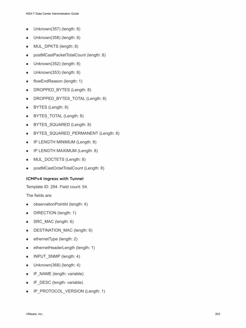
n Unknown(357) (length: 8)
n Unknown(358) (length: 8)
n MUL_DPKTS (length: 8)
n postMCastPacketTotalCount (length: 8)
n Unknown(352) (length: 8)
n Unknown(353) (length: 8)
n flowEndReason (length: 1)
n DROPPED_BYTES (Length: 8)
n DROPPED_BYTES_TOTAL (Length: 8)
n BYTES (Length: 8)
n BYTES_TOTAL (Length: 8)
n BYTES_SQUARED (Length: 8)
n BYTES_SQUARED_PERMANENT (Length: 8)
n IP LENGTH MINIMUM (Length: 8)
n IP LENGTH MAXIMUM (Length: 8)
n MUL_DOCTETS (Length: 8)
n postMCastOctetTotalCount (Length: 8)
ICMPv4 Ingress with Tunnel
Template ID: 294. Field count: 54.
The fields are:
n observationPointId (length: 4)
n DIRECTION (length: 1)
n SRC_MAC (length: 6)
n DESTINATION_MAC (length: 6)
n ethernetType (length: 2)
n ethernetHeaderLength (length: 1)
n INPUT_SNMP (length: 4)
n Unknown(368) (length: 4)
n IF_NAME (length: variable)
n IF_DESC (length: variable)
n IP_PROTOCOL_VERSION (Length: 1)
NSX-T Data Center Administration Guide
VMware, Inc. 303

n IP_TTL (Length: 1)
n PROTOCOL (Length: 1)
n IP_DSCP (Length: 1)
n IP_PRECEDENCE (Length: 1)
n IP_TOS (Length: 1)
n IP_SRC_ADDR (Length: 4)
n IP_DST_ADDR (Length: 4)
n ICMP_IPv4_TYPE (Length: 1)
n ICMP_IPv4_CODE (Length: 1)
n 893 (length: 4, PEN: VMware Inc. (6876))
n 894 (length: 4, PEN: VMware Inc. (6876))
n 895 (length: 1, PEN: VMware Inc. (6876))
n 896 (length: 2, PEN: VMware Inc. (6876))
n 897 (length: 2, PEN: VMware Inc. (6876))
n 891 (length: 1, PEN: VMware Inc. (6876))
n 892 (length: variable, PEN: VMware Inc. (6876))
n 898 (length: variable, PEN: VMware Inc. (6876))
n flowStartDeltaMicroseconds (length: 4)
n flowEndDeltaMicroseconds (length: 4)
n DROPPED_PACKETS (length: 8)
n DROPPED_PACKETS_TOTAL (length: 8)
n PKTS (length: 8)
n PACKETS_TOTAL (length: 8)
n Unknown(354) (length: 8)
n Unknown(355) (length: 8)
n Unknown(356) (length: 8)
n Unknown(357) (length: 8)
n Unknown(358) (length: 8)
n MUL_DPKTS (length: 8)
n postMCastPacketTotalCount (length: 8)
n Unknown(352) (length: 8)
n Unknown(353) (length: 8)
NSX-T Data Center Administration Guide
VMware, Inc. 304

n flowEndReason (length: 1)
n DROPPED_BYTES (Length: 8)
n DROPPED_BYTES_TOTAL (Length: 8)
n BYTES (Length: 8)
n BYTES_TOTAL (Length: 8)
n BYTES_SQUARED (Length: 8)
n BYTES_SQUARED_PERMANENT (Length: 8)
n IP LENGTH MINIMUM (Length: 8)
n IP LENGTH MAXIMUM (Length: 8)
n MUL_DOCTETS (Length: 8)
n postMCastOctetTotalCount (Length: 8)
ICMPv4 Egress with Tunnel
Template ID: 295. Field count: 58.
The fields are:
n observationPointId (length: 4)
n DIRECTION (length: 1)
n SRC_MAC (length: 6)
n DESTINATION_MAC (length: 6)
n ethernetType (length: 2)
n ethernetHeaderLength (length: 1)
n INPUT_SNMP (length: 4)
n Unknown(368) (length: 4)
n IF_NAME (length: variable)
n IF_DESC (length: variable)
n OUTPUT_SNMP (Length: 4)
n Unknown(369) (Length: 4)
n IF_NAME (Length: variable)
n IF_DESC (Length: variable)
n IP_PROTOCOL_VERSION (Length: 1)
n IP_TTL (Length: 1)
n PROTOCOL (Length: 1)
NSX-T Data Center Administration Guide
VMware, Inc. 305

n IP_DSCP (Length: 1)
n IP_PRECEDENCE (Length: 1)
n IP_TOS (Length: 1)
n IP_SRC_ADDR (Length: 4)
n IP_DST_ADDR (Length: 4)
n ICMP_IPv4_TYPE (Length: 1)
n ICMP_IPv4_CODE (Length: 1)
n 893 (length: 4, PEN: VMware Inc. (6876))
n 894 (length: 4, PEN: VMware Inc. (6876))
n 895 (length: 1, PEN: VMware Inc. (6876))
n 896 (length: 2, PEN: VMware Inc. (6876))
n 897 (length: 2, PEN: VMware Inc. (6876))
n 891 (length: 1, PEN: VMware Inc. (6876))
n 892 (length: variable, PEN: VMware Inc. (6876))
n 898 (length: variable, PEN: VMware Inc. (6876))
n flowStartDeltaMicroseconds (length: 4)
n flowEndDeltaMicroseconds (length: 4)
n DROPPED_PACKETS (length: 8)
n DROPPED_PACKETS_TOTAL (length: 8)
n PKTS (length: 8)
n PACKETS_TOTAL (length: 8)
n Unknown(354) (length: 8)
n Unknown(355) (length: 8)
n Unknown(356) (length: 8)
n Unknown(357) (length: 8)
n Unknown(358) (length: 8)
n MUL_DPKTS (length: 8)
n postMCastPacketTotalCount (length: 8)
n Unknown(352) (length: 8)
n Unknown(353) (length: 8)
n flowEndReason (length: 1)
n DROPPED_BYTES (Length: 8)
NSX-T Data Center Administration Guide
VMware, Inc. 306

n DROPPED_BYTES_TOTAL (Length: 8)
n BYTES (Length: 8)
n BYTES_TOTAL (Length: 8)
n BYTES_SQUARED (Length: 8)
n BYTES_SQUARED_PERMANENT (Length: 8)
n IP LENGTH MINIMUM (Length: 8)
n IP LENGTH MAXIMUM (Length: 8)
n MUL_DOCTETS (Length: 8)
n postMCastOctetTotalCount (Length: 8)
KVM IPv6 IPFIX TemplatesThere are four KVM IPv6 IPFIX templates: ingress, egress, ingress with tunnel, and egress with tunnel.
IPv6 Ingress
Template ID: 296. Field count: 46.
The fields are:
n observationPointId (length: 4)
n DIRECTION (length: 1)
n SRC_MAC (length: 6)
n DESTINATION_MAC (length: 6)
n ethernetType (length: 2)
n ethernetHeaderLength (length: 1)
n INPUT_SNMP (length: 4)
n Unknown(368) (length: 4)
n IF_NAME (length: variable)
n IF_DESC (length: variable)
n IP_PROTOCOL_VERSION (Length: 1)
n IP_TTL (Length: 1)
n PROTOCOL (Length: 1)
n IP_DSCP (Length: 1)
n IP_PRECEDENCE (Length: 1)
n IP_TOS (Length: 1)
n IPV6_SRC_ADDR (Length: 4)
NSX-T Data Center Administration Guide
VMware, Inc. 307

n IPV6_DST_ADDR (Length: 4)
n FLOW_LABEL (Length: 4)
n 898 (length: variable, PEN: VMware Inc. (6876))
n flowStartDeltaMicroseconds (length: 4)
n flowEndDeltaMicroseconds (length: 4)
n DROPPED_PACKETS (length: 8)
n DROPPED_PACKETS_TOTAL (length: 8)
n PKTS (length: 8)
n PACKETS_TOTAL (length: 8)
n Unknown(354) (length: 8)
n Unknown(355) (length: 8)
n Unknown(356) (length: 8)
n Unknown(357) (length: 8)
n Unknown(358) (length: 8)
n MUL_DPKTS (length: 8)
n postMCastPacketTotalCount (length: 8)
n Unknown(352) (length: 8)
n Unknown(353) (length: 8)
n flowEndReason (length: 1)
n DROPPED_BYTES (Length: 8)
n DROPPED_BYTES_TOTAL (Length: 8)
n BYTES (Length: 8)
n BYTES_TOTAL (Length: 8)
n BYTES_SQUARED (Length: 8)
n BYTES_SQUARED_PERMANENT (Length: 8)
n IP LENGTH MINIMUM (Length: 8)
n IP LENGTH MAXIMUM (Length: 8)
n MUL_DOCTETS (Length: 8)
n postMCastOctetTotalCount (Length: 8)
IPv6 Egress
Template ID: 297. Field count: 50.
NSX-T Data Center Administration Guide
VMware, Inc. 308

The fields are:
n observationPointId (length: 4)
n DIRECTION (length: 1)
n SRC_MAC (length: 6)
n DESTINATION_MAC (length: 6)
n ethernetType (length: 2)
n ethernetHeaderLength (length: 1)
n INPUT_SNMP (length: 4)
n Unknown(368) (length: 4)
n IF_NAME (length: variable)
n IF_DESC (length: variable)
n OUTPUT_SNMP (Length: 4)
n Unknown(369) (Length: 4)
n IF_NAME (Length: variable)
n IF_DESC (Length: variable)
n IP_PROTOCOL_VERSION (Length: 1)
n IP_TTL (Length: 1)
n PROTOCOL (Length: 1)
n IP_DSCP (Length: 1)
n IP_PRECEDENCE (Length: 1)
n IP_TOS (Length: 1)
n IPV6_SRC_ADDR (Length: 4)
n IPV6_DST_ADDR (Length: 4)
n FLOW_LABEL (Length: 4)
n 898 (length: variable, PEN: VMware Inc. (6876))
n flowStartDeltaMicroseconds (length: 4)
n flowEndDeltaMicroseconds (length: 4)
n DROPPED_PACKETS (length: 8)
n DROPPED_PACKETS_TOTAL (length: 8)
n PKTS (length: 8)
n PACKETS_TOTAL (length: 8)
n Unknown(354) (length: 8)
NSX-T Data Center Administration Guide
VMware, Inc. 309

n Unknown(355) (length: 8)
n Unknown(356) (length: 8)
n Unknown(357) (length: 8)
n Unknown(358) (length: 8)
n MUL_DPKTS (length: 8)
n postMCastPacketTotalCount (length: 8)
n Unknown(352) (length: 8)
n Unknown(353) (length: 8)
n flowEndReason (length: 1)
n DROPPED_BYTES (Length: 8)
n DROPPED_BYTES_TOTAL (Length: 8)
n BYTES (Length: 8)
n BYTES_TOTAL (Length: 8)
n BYTES_SQUARED (Length: 8)
n BYTES_SQUARED_PERMANENT (Length: 8)
n IP LENGTH MINIMUM (Length: 8)
n IP LENGTH MAXIMUM (Length: 8)
n MUL_DOCTETS (Length: 8)
n postMCastOctetTotalCount (Length: 8)
IPv6 Ingress with Tunnel
Template ID: 298. Field count: 53.
The fields are:
n observationPointId (length: 4)
n DIRECTION (length: 1)
n SRC_MAC (length: 6)
n DESTINATION_MAC (length: 6)
n ethernetType (length: 2)
n ethernetHeaderLength (length: 1)
n INPUT_SNMP (length: 4)
n Unknown(368) (length: 4)
n IF_NAME (length: variable)
NSX-T Data Center Administration Guide
VMware, Inc. 310

n IF_DESC (length: variable)
n IP_PROTOCOL_VERSION (Length: 1)
n IP_TTL (Length: 1)
n PROTOCOL (Length: 1)
n IP_DSCP (Length: 1)
n IP_PRECEDENCE (Length: 1)
n IP_TOS (Length: 1)
n IPV6_SRC_ADDR (Length: 4)
n IPV6_DST_ADDR (Length: 4)
n FLOW_LABEL (Length: 4)
n 893 (length: 4, PEN: VMware Inc. (6876))
n 894 (length: 4, PEN: VMware Inc. (6876))
n 895 (length: 1, PEN: VMware Inc. (6876))
n 896 (length: 2, PEN: VMware Inc. (6876))
n 897 (length: 2, PEN: VMware Inc. (6876))
n 891 (length: 1, PEN: VMware Inc. (6876))
n 892 (length: variable, PEN: VMware Inc. (6876))
n 898 (length: variable, PEN: VMware Inc. (6876))
n flowStartDeltaMicroseconds (length: 4)
n flowEndDeltaMicroseconds (length: 4)
n DROPPED_PACKETS (length: 8)
n DROPPED_PACKETS_TOTAL (length: 8)
n PKTS (length: 8)
n PACKETS_TOTAL (length: 8)
n Unknown(354) (length: 8)
n Unknown(355) (length: 8)
n Unknown(356) (length: 8)
n Unknown(357) (length: 8)
n Unknown(358) (length: 8)
n MUL_DPKTS (length: 8)
n postMCastPacketTotalCount (length: 8)
n Unknown(352) (length: 8)
NSX-T Data Center Administration Guide
VMware, Inc. 311

n Unknown(353) (length: 8)
n flowEndReason (length: 1)
n DROPPED_BYTES (Length: 8)
n DROPPED_BYTES_TOTAL (Length: 8)
n BYTES (Length: 8)
n BYTES_TOTAL (Length: 8)
n BYTES_SQUARED (Length: 8)
n BYTES_SQUARED_PERMANENT (Length: 8)
n IP LENGTH MINIMUM (Length: 8)
n IP LENGTH MAXIMUM (Length: 8)
n MUL_DOCTETS (Length: 8)
n postMCastOctetTotalCount (Length: 8)
IPv6 Egress with Tunnel
Template ID: 299. Field count: 57.
The fields are:
n observationPointId (length: 4)
n DIRECTION (length: 1)
n SRC_MAC (length: 6)
n DESTINATION_MAC (length: 6)
n ethernetType (length: 2)
n ethernetHeaderLength (length: 1)
n INPUT_SNMP (length: 4)
n Unknown(368) (length: 4)
n IF_NAME (length: variable)
n IF_DESC (length: variable)
n OUTPUT_SNMP (Length: 4)
n Unknown(369) (Length: 4)
n IF_NAME (Length: variable)
n IF_DESC (Length: variable)
n IP_PROTOCOL_VERSION (Length: 1)
n IP_TTL (Length: 1)
NSX-T Data Center Administration Guide
VMware, Inc. 312

n PROTOCOL (Length: 1)
n IP_DSCP (Length: 1)
n IP_PRECEDENCE (Length: 1)
n IP_TOS (Length: 1)
n IPV6_SRC_ADDR (Length: 4)
n IPV6_DST_ADDR (Length: 4)
n FLOW_LABEL (Length: 4)
n 893 (length: 4, PEN: VMware Inc. (6876))
n 894 (length: 4, PEN: VMware Inc. (6876))
n 895 (length: 1, PEN: VMware Inc. (6876))
n 896 (length: 2, PEN: VMware Inc. (6876))
n 897 (length: 2, PEN: VMware Inc. (6876))
n 891 (length: 1, PEN: VMware Inc. (6876))
n 892 (length: variable, PEN: VMware Inc. (6876))
n 898 (length: variable, PEN: VMware Inc. (6876))
n flowStartDeltaMicroseconds (length: 4)
n flowEndDeltaMicroseconds (length: 4)
n DROPPED_PACKETS (length: 8)
n DROPPED_PACKETS_TOTAL (length: 8)
n PKTS (length: 8)
n PACKETS_TOTAL (length: 8)
n Unknown(354) (length: 8)
n Unknown(355) (length: 8)
n Unknown(356) (length: 8)
n Unknown(357) (length: 8)
n Unknown(358) (length: 8)
n MUL_DPKTS (length: 8)
n postMCastPacketTotalCount (length: 8)
n Unknown(352) (length: 8)
n Unknown(353) (length: 8)
n flowEndReason (length: 1)
n DROPPED_BYTES (Length: 8)
NSX-T Data Center Administration Guide
VMware, Inc. 313

n DROPPED_BYTES_TOTAL (Length: 8)
n BYTES (Length: 8)
n BYTES_TOTAL (Length: 8)
n BYTES_SQUARED (Length: 8)
n BYTES_SQUARED_PERMANENT (Length: 8)
n IP LENGTH MINIMUM (Length: 8)
n IP LENGTH MAXIMUM (Length: 8)
n MUL_DOCTETS (Length: 8)
n postMCastOctetTotalCount (Length: 8)
KVM TCP over IPv6 IPFIX TemplatesThere are four KVM TCP over IPv6 IPFIX templates: ingress, egress, ingress with tunnel, and egress with tunnel.
TCP over IPv6 Ingress
Template ID: 300. Field count: 54.
The fields are:
n observationPointId (length: 4)
n DIRECTION (length: 1)
n SRC_MAC (length: 6)
n DESTINATION_MAC (length: 6)
n ethernetType (length: 2)
n ethernetHeaderLength (length: 1)
n INPUT_SNMP (length: 4)
n Unknown(368) (length: 4)
n IF_NAME (length: variable)
n IF_DESC (length: variable)
n IP_PROTOCOL_VERSION (Length: 1)
n IP_TTL (Length: 1)
n PROTOCOL (Length: 1)
n IP_DSCP (Length: 1)
n IP_PRECEDENCE (Length: 1)
n IP_TOS (Length: 1)
NSX-T Data Center Administration Guide
VMware, Inc. 314

n IPV6_SRC_ADDR (Length: 4)
n IPV6_DST_ADDR (Length: 4)
n FLOW_LABEL (Length: 4)
n L4_SRC_PORT (Length: 2)
n L4_DST_PORT (Length: 2)
n 898 (length: variable, PEN: VMware Inc. (6876))
n flowStartDeltaMicroseconds (length: 4)
n flowEndDeltaMicroseconds (length: 4)
n DROPPED_PACKETS (length: 8)
n DROPPED_PACKETS_TOTAL (length: 8)
n PKTS (length: 8)
n PACKETS_TOTAL (length: 8)
n Unknown(354) (length: 8)
n Unknown(355) (length: 8)
n Unknown(356) (length: 8)
n Unknown(357) (length: 8)
n Unknown(358) (length: 8)
n MUL_DPKTS (length: 8)
n postMCastPacketTotalCount (length: 8)
n Unknown(352) (length: 8)
n Unknown(353) (length: 8)
n flowEndReason (length: 1)
n DROPPED_BYTES (Length: 8)
n DROPPED_BYTES_TOTAL (Length: 8)
n BYTES (Length: 8)
n BYTES_TOTAL (Length: 8)
n BYTES_SQUARED (Length: 8)
n BYTES_SQUARED_PERMANENT (Length: 8)
n IP LENGTH MINIMUM (Length: 8)
n IP LENGTH MAXIMUM (Length: 8)
n MUL_DOCTETS (Length: 8)
n postMCastOctetTotalCount (Length: 8)
NSX-T Data Center Administration Guide
VMware, Inc. 315

n tcpAckTotalCount (Length: 8)
n tcpFinTotalCount (Length: 8)
n tcpPshTotalCount (Length: 8)
n tcpRstTotalCount (Length: 8)
n tcpSynTotalCount (Length: 8)
n tcpUrgTotalCount (Length: 8)
TCP over IPv6 Egress
Template ID: 301. Field count: 58.
The fields are:
n observationPointId (length: 4)
n DIRECTION (length: 1)
n SRC_MAC (length: 6)
n DESTINATION_MAC (length: 6)
n ethernetType (length: 2)
n ethernetHeaderLength (length: 1)
n INPUT_SNMP (length: 4)
n Unknown(368) (length: 4)
n IF_NAME (length: variable)
n IF_DESC (length: variable)
n OUTPUT_SNMP (Length: 4)
n Unknown(369) (Length: 4)
n IF_NAME (Length: variable)
n IF_DESC (Length: variable)
n IP_PROTOCOL_VERSION (Length: 1)
n IP_TTL (Length: 1)
n PROTOCOL (Length: 1)
n IP_DSCP (Length: 1)
n IP_PRECEDENCE (Length: 1)
n IP_TOS (Length: 1)
n IPV6_SRC_ADDR (Length: 4)
n IPV6_DST_ADDR (Length: 4)
NSX-T Data Center Administration Guide
VMware, Inc. 316

n FLOW_LABEL (Length: 4)
n L4_SRC_PORT (Length: 2)
n L4_DST_PORT (Length: 2)
n 898 (length: variable, PEN: VMware Inc. (6876))
n flowStartDeltaMicroseconds (length: 4)
n flowEndDeltaMicroseconds (length: 4)
n DROPPED_PACKETS (length: 8)
n DROPPED_PACKETS_TOTAL (length: 8)
n PKTS (length: 8)
n PACKETS_TOTAL (length: 8)
n Unknown(354) (length: 8)
n Unknown(355) (length: 8)
n Unknown(356) (length: 8)
n Unknown(357) (length: 8)
n Unknown(358) (length: 8)
n MUL_DPKTS (length: 8)
n postMCastPacketTotalCount (length: 8)
n Unknown(352) (length: 8)
n Unknown(353) (length: 8)
n flowEndReason (length: 1)
n DROPPED_BYTES (Length: 8)
n DROPPED_BYTES_TOTAL (Length: 8)
n BYTES (Length: 8)
n BYTES_TOTAL (Length: 8)
n BYTES_SQUARED (Length: 8)
n BYTES_SQUARED_PERMANENT (Length: 8)
n IP LENGTH MINIMUM (Length: 8)
n IP LENGTH MAXIMUM (Length: 8)
n MUL_DOCTETS (Length: 8)
n postMCastOctetTotalCount (Length: 8)
n tcpAckTotalCount (Length: 8)
n tcpFinTotalCount (Length: 8)
NSX-T Data Center Administration Guide
VMware, Inc. 317

n tcpPshTotalCount (Length: 8)
n tcpRstTotalCount (Length: 8)
n tcpSynTotalCount (Length: 8)
n tcpUrgTotalCount (Length: 8)
TCP over IPv6 Ingress with Tunnel
Template ID: 302. Field count: 61.
The fields are:
n observationPointId (length: 4)
n DIRECTION (length: 1)
n SRC_MAC (length: 6)
n DESTINATION_MAC (length: 6)
n ethernetType (length: 2)
n ethernetHeaderLength (length: 1)
n INPUT_SNMP (length: 4)
n Unknown(368) (length: 4)
n IF_NAME (length: variable)
n IF_DESC (length: variable)
n IP_PROTOCOL_VERSION (Length: 1)
n IP_TTL (Length: 1)
n PROTOCOL (Length: 1)
n IP_DSCP (Length: 1)
n IP_PRECEDENCE (Length: 1)
n IP_TOS (Length: 1)
n IPV6_SRC_ADDR (Length: 4)
n IPV6_DST_ADDR (Length: 4)
n FLOW_LABEL (Length: 4)
n L4_SRC_PORT (Length: 2)
n L4_DST_PORT (Length: 2)
n 893 (length: 4, PEN: VMware Inc. (6876))
n 894 (length: 4, PEN: VMware Inc. (6876))
n 895 (length: 1, PEN: VMware Inc. (6876))
NSX-T Data Center Administration Guide
VMware, Inc. 318

n 896 (length: 2, PEN: VMware Inc. (6876))
n 897 (length: 2, PEN: VMware Inc. (6876))
n 891 (length: 1, PEN: VMware Inc. (6876))
n 892 (length: variable, PEN: VMware Inc. (6876))
n 898 (length: variable, PEN: VMware Inc. (6876))
n flowStartDeltaMicroseconds (length: 4)
n flowEndDeltaMicroseconds (length: 4)
n DROPPED_PACKETS (length: 8)
n DROPPED_PACKETS_TOTAL (length: 8)
n PKTS (length: 8)
n PACKETS_TOTAL (length: 8)
n Unknown(354) (length: 8)
n Unknown(355) (length: 8)
n Unknown(356) (length: 8)
n Unknown(357) (length: 8)
n Unknown(358) (length: 8)
n MUL_DPKTS (length: 8)
n postMCastPacketTotalCount (length: 8)
n Unknown(352) (length: 8)
n Unknown(353) (length: 8)
n flowEndReason (length: 1)
n DROPPED_BYTES (Length: 8)
n DROPPED_BYTES_TOTAL (Length: 8)
n BYTES (Length: 8)
n BYTES_TOTAL (Length: 8)
n BYTES_SQUARED (Length: 8)
n BYTES_SQUARED_PERMANENT (Length: 8)
n IP LENGTH MINIMUM (Length: 8)
n IP LENGTH MAXIMUM (Length: 8)
n MUL_DOCTETS (Length: 8)
n postMCastOctetTotalCount (Length: 8)
n tcpAckTotalCount (Length: 8)
NSX-T Data Center Administration Guide
VMware, Inc. 319

n tcpFinTotalCount (Length: 8)
n tcpPshTotalCount (Length: 8)
n tcpRstTotalCount (Length: 8)
n tcpSynTotalCount (Length: 8)
n tcpUrgTotalCount (Length: 8)
TCP over IPv6 Egress with Tunnel
Template ID: 303. Field count: 65.
The fields are:
n observationPointId (length: 4)
n DIRECTION (length: 1)
n SRC_MAC (length: 6)
n DESTINATION_MAC (length: 6)
n ethernetType (length: 2)
n ethernetHeaderLength (length: 1)
n INPUT_SNMP (length: 4)
n Unknown(368) (length: 4)
n IF_NAME (length: variable)
n IF_DESC (length: variable)
n OUTPUT_SNMP (Length: 4)
n Unknown(369) (Length: 4)
n IF_NAME (Length: variable)
n IF_DESC (Length: variable)
n IP_PROTOCOL_VERSION (Length: 1)
n IP_TTL (Length: 1)
n PROTOCOL (Length: 1)
n IP_DSCP (Length: 1)
n IP_PRECEDENCE (Length: 1)
n IP_TOS (Length: 1)
n IPV6_SRC_ADDR (Length: 4)
n IPV6_DST_ADDR (Length: 4)
n FLOW_LABEL (Length: 4)
NSX-T Data Center Administration Guide
VMware, Inc. 320

n L4_SRC_PORT (Length: 2)
n L4_DST_PORT (Length: 2)
n 893 (length: 4, PEN: VMware Inc. (6876))
n 894 (length: 4, PEN: VMware Inc. (6876))
n 895 (length: 1, PEN: VMware Inc. (6876))
n 896 (length: 2, PEN: VMware Inc. (6876))
n 897 (length: 2, PEN: VMware Inc. (6876))
n 891 (length: 1, PEN: VMware Inc. (6876))
n 892 (length: variable, PEN: VMware Inc. (6876))
n 898 (length: variable, PEN: VMware Inc. (6876))
n flowStartDeltaMicroseconds (length: 4)
n flowEndDeltaMicroseconds (length: 4)
n DROPPED_PACKETS (length: 8)
n DROPPED_PACKETS_TOTAL (length: 8)
n PKTS (length: 8)
n PACKETS_TOTAL (length: 8)
n Unknown(354) (length: 8)
n Unknown(355) (length: 8)
n Unknown(356) (length: 8)
n Unknown(357) (length: 8)
n Unknown(358) (length: 8)
n MUL_DPKTS (length: 8)
n postMCastPacketTotalCount (length: 8)
n Unknown(352) (length: 8)
n Unknown(353) (length: 8)
n flowEndReason (length: 1)
n DROPPED_BYTES (Length: 8)
n DROPPED_BYTES_TOTAL (Length: 8)
n BYTES (Length: 8)
n BYTES_TOTAL (Length: 8)
n BYTES_SQUARED (Length: 8)
n BYTES_SQUARED_PERMANENT (Length: 8)
NSX-T Data Center Administration Guide
VMware, Inc. 321
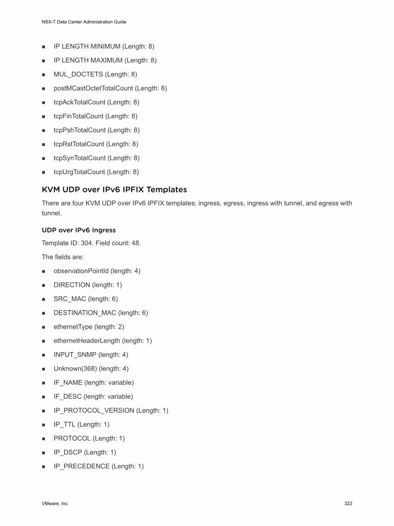
n IP LENGTH MINIMUM (Length: 8)
n IP LENGTH MAXIMUM (Length: 8)
n MUL_DOCTETS (Length: 8)
n postMCastOctetTotalCount (Length: 8)
n tcpAckTotalCount (Length: 8)
n tcpFinTotalCount (Length: 8)
n tcpPshTotalCount (Length: 8)
n tcpRstTotalCount (Length: 8)
n tcpSynTotalCount (Length: 8)
n tcpUrgTotalCount (Length: 8)
KVM UDP over IPv6 IPFIX TemplatesThere are four KVM UDP over IPv6 IPFIX templates: ingress, egress, ingress with tunnel, and egress with tunnel.
UDP over IPv6 Ingress
Template ID: 304. Field count: 48.
The fields are:
n observationPointId (length: 4)
n DIRECTION (length: 1)
n SRC_MAC (length: 6)
n DESTINATION_MAC (length: 6)
n ethernetType (length: 2)
n ethernetHeaderLength (length: 1)
n INPUT_SNMP (length: 4)
n Unknown(368) (length: 4)
n IF_NAME (length: variable)
n IF_DESC (length: variable)
n IP_PROTOCOL_VERSION (Length: 1)
n IP_TTL (Length: 1)
n PROTOCOL (Length: 1)
n IP_DSCP (Length: 1)
n IP_PRECEDENCE (Length: 1)
NSX-T Data Center Administration Guide
VMware, Inc. 322

n IP_TOS (Length: 1)
n IPV6_SRC_ADDR (Length: 4)
n IPV6_DST_ADDR (Length: 4)
n FLOW_LABEL (Length: 4)
n L4_SRC_PORT (Length: 2)
n L4_DST_PORT (Length: 2)
n 898 (length: variable, PEN: VMware Inc. (6876))
n flowStartDeltaMicroseconds (length: 4)
n flowEndDeltaMicroseconds (length: 4)
n DROPPED_PACKETS (length: 8)
n DROPPED_PACKETS_TOTAL (length: 8)
n PKTS (length: 8)
n PACKETS_TOTAL (length: 8)
n Unknown(354) (length: 8)
n Unknown(355) (length: 8)
n Unknown(356) (length: 8)
n Unknown(357) (length: 8)
n Unknown(358) (length: 8)
n MUL_DPKTS (length: 8)
n postMCastPacketTotalCount (length: 8)
n Unknown(352) (length: 8)
n Unknown(353) (length: 8)
n flowEndReason (length: 1)
n DROPPED_BYTES (Length: 8)
n DROPPED_BYTES_TOTAL (Length: 8)
n BYTES (Length: 8)
n BYTES_TOTAL (Length: 8)
n BYTES_SQUARED (Length: 8)
n BYTES_SQUARED_PERMANENT (Length: 8)
n IP LENGTH MINIMUM (Length: 8)
n IP LENGTH MAXIMUM (Length: 8)
n MUL_DOCTETS (Length: 8)
NSX-T Data Center Administration Guide
VMware, Inc. 323

n postMCastOctetTotalCount (Length: 8)
UDP over IPv6 Egress
Template ID: 305. Field count: 52.
The fields are:
n observationPointId (length: 4)
n DIRECTION (length: 1)
n SRC_MAC (length: 6)
n DESTINATION_MAC (length: 6)
n ethernetType (length: 2)
n ethernetHeaderLength (length: 1)
n INPUT_SNMP (length: 4)
n Unknown(368) (length: 4)
n IF_NAME (length: variable)
n IF_DESC (length: variable)
n OUTPUT_SNMP (Length: 4)
n Unknown(369) (Length: 4)
n IF_NAME (Length: variable)
n IF_DESC (Length: variable)
n IP_PROTOCOL_VERSION (Length: 1)
n IP_TTL (Length: 1)
n PROTOCOL (Length: 1)
n IP_DSCP (Length: 1)
n IP_PRECEDENCE (Length: 1)
n IP_TOS (Length: 1)
n IPV6_SRC_ADDR (Length: 4)
n IPV6_DST_ADDR (Length: 4)
n FLOW_LABEL (Length: 4)
n L4_SRC_PORT (Length: 2)
n L4_DST_PORT (Length: 2)
n 898 (length: variable, PEN: VMware Inc. (6876))
n flowStartDeltaMicroseconds (length: 4)
NSX-T Data Center Administration Guide
VMware, Inc. 324

n flowEndDeltaMicroseconds (length: 4)
n DROPPED_PACKETS (length: 8)
n DROPPED_PACKETS_TOTAL (length: 8)
n PKTS (length: 8)
n PACKETS_TOTAL (length: 8)
n Unknown(354) (length: 8)
n Unknown(355) (length: 8)
n Unknown(356) (length: 8)
n Unknown(357) (length: 8)
n Unknown(358) (length: 8)
n MUL_DPKTS (length: 8)
n postMCastPacketTotalCount (length: 8)
n Unknown(352) (length: 8)
n Unknown(353) (length: 8)
n flowEndReason (length: 1)
n DROPPED_BYTES (Length: 8)
n DROPPED_BYTES_TOTAL (Length: 8)
n BYTES (Length: 8)
n BYTES_TOTAL (Length: 8)
n BYTES_SQUARED (Length: 8)
n BYTES_SQUARED_PERMANENT (Length: 8)
n IP LENGTH MINIMUM (Length: 8)
n IP LENGTH MAXIMUM (Length: 8)
n MUL_DOCTETS (Length: 8)
n postMCastOctetTotalCount (Length: 8)
UDP over IPv6 Ingress with Tunnel
Template ID: 306. Field count: 55.
The fields are:
n observationPointId (length: 4)
n DIRECTION (length: 1)
n SRC_MAC (length: 6)
NSX-T Data Center Administration Guide
VMware, Inc. 325

n DESTINATION_MAC (length: 6)
n ethernetType (length: 2)
n ethernetHeaderLength (length: 1)
n INPUT_SNMP (length: 4)
n Unknown(368) (length: 4)
n IF_NAME (length: variable)
n IF_DESC (length: variable)
n IP_PROTOCOL_VERSION (Length: 1)
n IP_TTL (Length: 1)
n PROTOCOL (Length: 1)
n IP_DSCP (Length: 1)
n IP_PRECEDENCE (Length: 1)
n IP_TOS (Length: 1)
n IPV6_SRC_ADDR (Length: 4)
n IPV6_DST_ADDR (Length: 4)
n FLOW_LABEL (Length: 4)
n L4_SRC_PORT (Length: 2)
n L4_DST_PORT (Length: 2)
n 893 (length: 4, PEN: VMware Inc. (6876))
n 894 (length: 4, PEN: VMware Inc. (6876))
n 895 (length: 1, PEN: VMware Inc. (6876))
n 896 (length: 2, PEN: VMware Inc. (6876))
n 897 (length: 2, PEN: VMware Inc. (6876))
n 891 (length: 1, PEN: VMware Inc. (6876))
n 892 (length: variable, PEN: VMware Inc. (6876))
n 898 (length: variable, PEN: VMware Inc. (6876))
n flowStartDeltaMicroseconds (length: 4)
n flowEndDeltaMicroseconds (length: 4)
n DROPPED_PACKETS (length: 8)
n DROPPED_PACKETS_TOTAL (length: 8)
n PKTS (length: 8)
n PACKETS_TOTAL (length: 8)
NSX-T Data Center Administration Guide
VMware, Inc. 326

n Unknown(354) (length: 8)
n Unknown(355) (length: 8)
n Unknown(356) (length: 8)
n Unknown(357) (length: 8)
n Unknown(358) (length: 8)
n MUL_DPKTS (length: 8)
n postMCastPacketTotalCount (length: 8)
n Unknown(352) (length: 8)
n Unknown(353) (length: 8)
n flowEndReason (length: 1)
n DROPPED_BYTES (Length: 8)
n DROPPED_BYTES_TOTAL (Length: 8)
n BYTES (Length: 8)
n BYTES_TOTAL (Length: 8)
n BYTES_SQUARED (Length: 8)
n BYTES_SQUARED_PERMANENT (Length: 8)
n IP LENGTH MINIMUM (Length: 8)
n IP LENGTH MAXIMUM (Length: 8)
n MUL_DOCTETS (Length: 8)
n postMCastOctetTotalCount (Length: 8)
UDP over IPv6 Egress with Tunnel
Template ID: 307. Field count: 59.
The fields are:
n observationPointId (length: 4)
n DIRECTION (length: 1)
n SRC_MAC (length: 6)
n DESTINATION_MAC (length: 6)
n ethernetType (length: 2)
n ethernetHeaderLength (length: 1)
n INPUT_SNMP (length: 4)
n Unknown(368) (length: 4)
NSX-T Data Center Administration Guide
VMware, Inc. 327

n IF_NAME (length: variable)
n IF_DESC (length: variable)
n OUTPUT_SNMP (Length: 4)
n Unknown(369) (Length: 4)
n IF_NAME (Length: variable)
n IF_DESC (Length: variable)
n IP_PROTOCOL_VERSION (Length: 1)
n IP_TTL (Length: 1)
n PROTOCOL (Length: 1)
n IP_DSCP (Length: 1)
n IP_PRECEDENCE (Length: 1)
n IP_TOS (Length: 1)
n IPV6_SRC_ADDR (Length: 4)
n IPV6_DST_ADDR (Length: 4)
n FLOW_LABEL (Length: 4)
n L4_SRC_PORT (Length: 2)
n L4_DST_PORT (Length: 2)
n 893 (length: 4, PEN: VMware Inc. (6876))
n 894 (length: 4, PEN: VMware Inc. (6876))
n 895 (length: 1, PEN: VMware Inc. (6876))
n 896 (length: 2, PEN: VMware Inc. (6876))
n 897 (length: 2, PEN: VMware Inc. (6876))
n 891 (length: 1, PEN: VMware Inc. (6876))
n 892 (length: variable, PEN: VMware Inc. (6876))
n 898 (length: variable, PEN: VMware Inc. (6876))
n flowStartDeltaMicroseconds (length: 4)
n flowEndDeltaMicroseconds (length: 4)
n DROPPED_PACKETS (length: 8)
n DROPPED_PACKETS_TOTAL (length: 8)
n PKTS (length: 8)
n PACKETS_TOTAL (length: 8)
n Unknown(354) (length: 8)
NSX-T Data Center Administration Guide
VMware, Inc. 328

n Unknown(355) (length: 8)
n Unknown(356) (length: 8)
n Unknown(357) (length: 8)
n Unknown(358) (length: 8)
n MUL_DPKTS (length: 8)
n postMCastPacketTotalCount (length: 8)
n Unknown(352) (length: 8)
n Unknown(353) (length: 8)
n flowEndReason (length: 1)
n DROPPED_BYTES (Length: 8)
n DROPPED_BYTES_TOTAL (Length: 8)
n BYTES (Length: 8)
n BYTES_TOTAL (Length: 8)
n BYTES_SQUARED (Length: 8)
n BYTES_SQUARED_PERMANENT (Length: 8)
n IP LENGTH MINIMUM (Length: 8)
n IP LENGTH MAXIMUM (Length: 8)
n MUL_DOCTETS (Length: 8)
n postMCastOctetTotalCount (Length: 8)
KVM SCTP over IPv6 IPFIX TemplatesThere are four KVM SCTP over IPv6 IPFIX templates: ingress, egress, ingress with tunnel, and egress with tunnel.
SCTP over IPv6 Ingress
Template ID: 308. Field count: 48.
The fields are:
n observationPointId (length: 4)
n DIRECTION (length: 1)
n SRC_MAC (length: 6)
n DESTINATION_MAC (length: 6)
n ethernetType (length: 2)
n ethernetHeaderLength (length: 1)
NSX-T Data Center Administration Guide
VMware, Inc. 329

n INPUT_SNMP (length: 4)
n Unknown(368) (length: 4)
n IF_NAME (length: variable)
n IF_DESC (length: variable)
n IP_PROTOCOL_VERSION (Length: 1)
n IP_TTL (Length: 1)
n PROTOCOL (Length: 1)
n IP_DSCP (Length: 1)
n IP_PRECEDENCE (Length: 1)
n IP_TOS (Length: 1)
n IPV6_SRC_ADDR (Length: 4)
n IPV6_DST_ADDR (Length: 4)
n FLOW_LABEL (Length: 4)
n L4_SRC_PORT (Length: 2)
n L4_DST_PORT (Length: 2)
n 898 (length: variable, PEN: VMware Inc. (6876))
n flowStartDeltaMicroseconds (length: 4)
n flowEndDeltaMicroseconds (length: 4)
n DROPPED_PACKETS (length: 8)
n DROPPED_PACKETS_TOTAL (length: 8)
n PKTS (length: 8)
n PACKETS_TOTAL (length: 8)
n Unknown(354) (length: 8)
n Unknown(355) (length: 8)
n Unknown(356) (length: 8)
n Unknown(357) (length: 8)
n Unknown(358) (length: 8)
n MUL_DPKTS (length: 8)
n postMCastPacketTotalCount (length: 8)
n Unknown(352) (length: 8)
n Unknown(353) (length: 8)
n flowEndReason (length: 1)
NSX-T Data Center Administration Guide
VMware, Inc. 330

n DROPPED_BYTES (Length: 8)
n DROPPED_BYTES_TOTAL (Length: 8)
n BYTES (Length: 8)
n BYTES_TOTAL (Length: 8)
n BYTES_SQUARED (Length: 8)
n BYTES_SQUARED_PERMANENT (Length: 8)
n IP LENGTH MINIMUM (Length: 8)
n IP LENGTH MAXIMUM (Length: 8)
n MUL_DOCTETS (Length: 8)
n postMCastOctetTotalCount (Length: 8)
SCTP over IPv6 Egress
Template ID: 309. Field count: 52.
The fields are:
n observationPointId (length: 4)
n DIRECTION (length: 1)
n SRC_MAC (length: 6)
n DESTINATION_MAC (length: 6)
n ethernetType (length: 2)
n ethernetHeaderLength (length: 1)
n INPUT_SNMP (length: 4)
n Unknown(368) (length: 4)
n IF_NAME (length: variable)
n IF_DESC (length: variable)
n OUTPUT_SNMP (Length: 4)
n Unknown(369) (Length: 4)
n IF_NAME (Length: variable)
n IF_DESC (Length: variable)
n IP_PROTOCOL_VERSION (Length: 1)
n IP_TTL (Length: 1)
n PROTOCOL (Length: 1)
n IP_DSCP (Length: 1)
NSX-T Data Center Administration Guide
VMware, Inc. 331

n IP_PRECEDENCE (Length: 1)
n IP_TOS (Length: 1)
n IPV6_SRC_ADDR (Length: 4)
n IPV6_DST_ADDR (Length: 4)
n FLOW_LABEL (Length: 4)
n L4_SRC_PORT (Length: 2)
n L4_DST_PORT (Length: 2)
n 898 (length: variable, PEN: VMware Inc. (6876))
n flowStartDeltaMicroseconds (length: 4)
n flowEndDeltaMicroseconds (length: 4)
n DROPPED_PACKETS (length: 8)
n DROPPED_PACKETS_TOTAL (length: 8)
n PKTS (length: 8)
n PACKETS_TOTAL (length: 8)
n Unknown(354) (length: 8)
n Unknown(355) (length: 8)
n Unknown(356) (length: 8)
n Unknown(357) (length: 8)
n Unknown(358) (length: 8)
n MUL_DPKTS (length: 8)
n postMCastPacketTotalCount (length: 8)
n Unknown(352) (length: 8)
n Unknown(353) (length: 8)
n flowEndReason (length: 1)
n DROPPED_BYTES (Length: 8)
n DROPPED_BYTES_TOTAL (Length: 8)
n BYTES (Length: 8)
n BYTES_TOTAL (Length: 8)
n BYTES_SQUARED (Length: 8)
n BYTES_SQUARED_PERMANENT (Length: 8)
n IP LENGTH MINIMUM (Length: 8)
n IP LENGTH MAXIMUM (Length: 8)
NSX-T Data Center Administration Guide
VMware, Inc. 332

n MUL_DOCTETS (Length: 8)
n postMCastOctetTotalCount (Length: 8)
SCTP over IPv6 Ingress with Tunnel
Template ID: 310. Field count: 55.
The fields are:
n observationPointId (length: 4)
n DIRECTION (length: 1)
n SRC_MAC (length: 6)
n DESTINATION_MAC (length: 6)
n ethernetType (length: 2)
n ethernetHeaderLength (length: 1)
n INPUT_SNMP (length: 4)
n Unknown(368) (length: 4)
n IF_NAME (length: variable)
n IF_DESC (length: variable)
n IP_PROTOCOL_VERSION (Length: 1)
n IP_TTL (Length: 1)
n PROTOCOL (Length: 1)
n IP_DSCP (Length: 1)
n IP_PRECEDENCE (Length: 1)
n IP_TOS (Length: 1)
n IPV6_SRC_ADDR (Length: 4)
n IPV6_DST_ADDR (Length: 4)
n FLOW_LABEL (Length: 4)
n L4_SRC_PORT (Length: 2)
n L4_DST_PORT (Length: 2)
n 893 (length: 4, PEN: VMware Inc. (6876))
n 894 (length: 4, PEN: VMware Inc. (6876))
n 895 (length: 1, PEN: VMware Inc. (6876))
n 896 (length: 2, PEN: VMware Inc. (6876))
n 897 (length: 2, PEN: VMware Inc. (6876))
NSX-T Data Center Administration Guide
VMware, Inc. 333

n 891 (length: 1, PEN: VMware Inc. (6876))
n 892 (length: variable, PEN: VMware Inc. (6876))
n 898 (length: variable, PEN: VMware Inc. (6876))
n flowStartDeltaMicroseconds (length: 4)
n flowEndDeltaMicroseconds (length: 4)
n DROPPED_PACKETS (length: 8)
n DROPPED_PACKETS_TOTAL (length: 8)
n PKTS (length: 8)
n PACKETS_TOTAL (length: 8)
n Unknown(354) (length: 8)
n Unknown(355) (length: 8)
n Unknown(356) (length: 8)
n Unknown(357) (length: 8)
n Unknown(358) (length: 8)
n MUL_DPKTS (length: 8)
n postMCastPacketTotalCount (length: 8)
n Unknown(352) (length: 8)
n Unknown(353) (length: 8)
n flowEndReason (length: 1)
n DROPPED_BYTES (Length: 8)
n DROPPED_BYTES_TOTAL (Length: 8)
n BYTES (Length: 8)
n BYTES_TOTAL (Length: 8)
n BYTES_SQUARED (Length: 8)
n BYTES_SQUARED_PERMANENT (Length: 8)
n IP LENGTH MINIMUM (Length: 8)
n IP LENGTH MAXIMUM (Length: 8)
n MUL_DOCTETS (Length: 8)
n postMCastOctetTotalCount (Length: 8)
SCTP over IPv6 Egress with Tunnel
Template ID: 311. Field count: 59.
NSX-T Data Center Administration Guide
VMware, Inc. 334

The fields are:
n observationPointId (length: 4)
n DIRECTION (length: 1)
n SRC_MAC (length: 6)
n DESTINATION_MAC (length: 6)
n ethernetType (length: 2)
n ethernetHeaderLength (length: 1)
n INPUT_SNMP (length: 4)
n Unknown(368) (length: 4)
n IF_NAME (length: variable)
n IF_DESC (length: variable)
n OUTPUT_SNMP (Length: 4)
n Unknown(369) (Length: 4)
n IF_NAME (Length: variable)
n IF_DESC (Length: variable)
n IP_PROTOCOL_VERSION (Length: 1)
n IP_TTL (Length: 1)
n PROTOCOL (Length: 1)
n IP_DSCP (Length: 1)
n IP_PRECEDENCE (Length: 1)
n IP_TOS (Length: 1)
n IPV6_SRC_ADDR (Length: 4)
n IPV6_DST_ADDR (Length: 4)
n FLOW_LABEL (Length: 4)
n L4_SRC_PORT (Length: 2)
n L4_DST_PORT (Length: 2)
n 893 (length: 4, PEN: VMware Inc. (6876))
n 894 (length: 4, PEN: VMware Inc. (6876))
n 895 (length: 1, PEN: VMware Inc. (6876))
n 896 (length: 2, PEN: VMware Inc. (6876))
n 897 (length: 2, PEN: VMware Inc. (6876))
n 891 (length: 1, PEN: VMware Inc. (6876))
NSX-T Data Center Administration Guide
VMware, Inc. 335

n 892 (length: variable, PEN: VMware Inc. (6876))
n 898 (length: variable, PEN: VMware Inc. (6876))
n flowStartDeltaMicroseconds (length: 4)
n flowEndDeltaMicroseconds (length: 4)
n DROPPED_PACKETS (length: 8)
n DROPPED_PACKETS_TOTAL (length: 8)
n PKTS (length: 8)
n PACKETS_TOTAL (length: 8)
n Unknown(354) (length: 8)
n Unknown(355) (length: 8)
n Unknown(356) (length: 8)
n Unknown(357) (length: 8)
n Unknown(358) (length: 8)
n MUL_DPKTS (length: 8)
n postMCastPacketTotalCount (length: 8)
n Unknown(352) (length: 8)
n Unknown(353) (length: 8)
n flowEndReason (length: 1)
n DROPPED_BYTES (Length: 8)
n DROPPED_BYTES_TOTAL (Length: 8)
n BYTES (Length: 8)
n BYTES_TOTAL (Length: 8)
n BYTES_SQUARED (Length: 8)
n BYTES_SQUARED_PERMANENT (Length: 8)
n IP LENGTH MINIMUM (Length: 8)
n IP LENGTH MAXIMUM (Length: 8)
n MUL_DOCTETS (Length: 8)
n postMCastOctetTotalCount (Length: 8)
KVM ICMPv6 IPFIX TemplatesThere are four KVM ICMPv6 IPFIX templates: ingress, egress, ingress with tunnel, and egress with tunnel.
NSX-T Data Center Administration Guide
VMware, Inc. 336

ICMPv6 Ingress
Template ID: 312. Field count: 48.
The fields are:
n observationPointId (length: 4)
n DIRECTION (length: 1)
n SRC_MAC (length: 6)
n DESTINATION_MAC (length: 6)
n ethernetType (length: 2)
n ethernetHeaderLength (length: 1)
n INPUT_SNMP (length: 4)
n Unknown(368) (length: 4)
n IF_NAME (length: variable)
n IF_DESC (length: variable)
n IP_PROTOCOL_VERSION (Length: 1)
n IP_TTL (Length: 1)
n PROTOCOL (Length: 1)
n IP_DSCP (Length: 1)
n IP_PRECEDENCE (Length: 1)
n IP_TOS (Length: 1)
n IPV6_SRC_ADDR (Length: 4)
n IPV6_DST_ADDR (Length: 4)
n FLOW_LABEL (Length: 4)
n ICMP_IPv6_TYPE (Length: 1)
n ICMP_IPv6_CODE (Length: 1)
n 898 (length: variable, PEN: VMware Inc. (6876))
n flowStartDeltaMicroseconds (length: 4)
n flowEndDeltaMicroseconds (length: 4)
n DROPPED_PACKETS (length: 8)
n DROPPED_PACKETS_TOTAL (length: 8)
n PKTS (length: 8)
n PACKETS_TOTAL (length: 8)
n Unknown(354) (length: 8)
NSX-T Data Center Administration Guide
VMware, Inc. 337

n Unknown(355) (length: 8)
n Unknown(356) (length: 8)
n Unknown(357) (length: 8)
n Unknown(358) (length: 8)
n MUL_DPKTS (length: 8)
n postMCastPacketTotalCount (length: 8)
n Unknown(352) (length: 8)
n Unknown(353) (length: 8)
n flowEndReason (length: 1)
n DROPPED_BYTES (Length: 8)
n DROPPED_BYTES_TOTAL (Length: 8)
n BYTES (Length: 8)
n BYTES_TOTAL (Length: 8)
n BYTES_SQUARED (Length: 8)
n BYTES_SQUARED_PERMANENT (Length: 8)
n IP LENGTH MINIMUM (Length: 8)
n IP LENGTH MAXIMUM (Length: 8)
n MUL_DOCTETS (Length: 8)
n postMCastOctetTotalCount (Length: 8)
ICMPv6 Egress
Template ID: 313. Field count: 52.
The fields are:
n observationPointId (length: 4)
n DIRECTION (length: 1)
n SRC_MAC (length: 6)
n DESTINATION_MAC (length: 6)
n ethernetType (length: 2)
n ethernetHeaderLength (length: 1)
n INPUT_SNMP (length: 4)
n Unknown(368) (length: 4)
n IF_NAME (length: variable)
NSX-T Data Center Administration Guide
VMware, Inc. 338

n IF_DESC (length: variable)
n OUTPUT_SNMP (Length: 4)
n Unknown(369) (Length: 4)
n IF_NAME (Length: variable)
n IF_DESC (Length: variable)
n IP_PROTOCOL_VERSION (Length: 1)
n IP_TTL (Length: 1)
n PROTOCOL (Length: 1)
n IP_DSCP (Length: 1)
n IP_PRECEDENCE (Length: 1)
n IP_TOS (Length: 1)
n IPV6_SRC_ADDR (Length: 4)
n IPV6_DST_ADDR (Length: 4)
n FLOW_LABEL (Length: 4)
n ICMP_IPv6_TYPE (Length: 1)
n ICMP_IPv6_CODE (Length: 1)
n 898 (length: variable, PEN: VMware Inc. (6876))
n flowStartDeltaMicroseconds (length: 4)
n flowEndDeltaMicroseconds (length: 4)
n DROPPED_PACKETS (length: 8)
n DROPPED_PACKETS_TOTAL (length: 8)
n PKTS (length: 8)
n PACKETS_TOTAL (length: 8)
n Unknown(354) (length: 8)
n Unknown(355) (length: 8)
n Unknown(356) (length: 8)
n Unknown(357) (length: 8)
n Unknown(358) (length: 8)
n MUL_DPKTS (length: 8)
n postMCastPacketTotalCount (length: 8)
n Unknown(352) (length: 8)
n Unknown(353) (length: 8)
NSX-T Data Center Administration Guide
VMware, Inc. 339

n flowEndReason (length: 1)
n DROPPED_BYTES (Length: 8)
n DROPPED_BYTES_TOTAL (Length: 8)
n BYTES (Length: 8)
n BYTES_TOTAL (Length: 8)
n BYTES_SQUARED (Length: 8)
n BYTES_SQUARED_PERMANENT (Length: 8)
n IP LENGTH MINIMUM (Length: 8)
n IP LENGTH MAXIMUM (Length: 8)
n MUL_DOCTETS (Length: 8)
n postMCastOctetTotalCount (Length: 8)
ICMPv6 Ingress with Tunnel
Template ID: 314. Field count: 55.
The fields are:
n observationPointId (length: 4)
n DIRECTION (length: 1)
n SRC_MAC (length: 6)
n DESTINATION_MAC (length: 6)
n ethernetType (length: 2)
n ethernetHeaderLength (length: 1)
n INPUT_SNMP (length: 4)
n Unknown(368) (length: 4)
n IF_NAME (length: variable)
n IF_DESC (length: variable)
n IP_PROTOCOL_VERSION (Length: 1)
n IP_TTL (Length: 1)
n PROTOCOL (Length: 1)
n IP_DSCP (Length: 1)
n IP_PRECEDENCE (Length: 1)
n IP_TOS (Length: 1)
n IPV6_SRC_ADDR (Length: 4)
NSX-T Data Center Administration Guide
VMware, Inc. 340

n IPV6_DST_ADDR (Length: 4)
n FLOW_LABEL (Length: 4)
n ICMP_IPv6_TYPE (Length: 1)
n ICMP_IPv6_CODE (Length: 1)
n 893 (length: 4, PEN: VMware Inc. (6876))
n 894 (length: 4, PEN: VMware Inc. (6876))
n 895 (length: 1, PEN: VMware Inc. (6876))
n 896 (length: 2, PEN: VMware Inc. (6876))
n 897 (length: 2, PEN: VMware Inc. (6876))
n 891 (length: 1, PEN: VMware Inc. (6876))
n 892 (length: variable, PEN: VMware Inc. (6876))
n 898 (length: variable, PEN: VMware Inc. (6876))
n flowStartDeltaMicroseconds (length: 4)
n flowEndDeltaMicroseconds (length: 4)
n DROPPED_PACKETS (length: 8)
n DROPPED_PACKETS_TOTAL (length: 8)
n PKTS (length: 8)
n PACKETS_TOTAL (length: 8)
n Unknown(354) (length: 8)
n Unknown(355) (length: 8)
n Unknown(356) (length: 8)
n Unknown(357) (length: 8)
n Unknown(358) (length: 8)
n MUL_DPKTS (length: 8)
n postMCastPacketTotalCount (length: 8)
n Unknown(352) (length: 8)
n Unknown(353) (length: 8)
n flowEndReason (length: 1)
n DROPPED_BYTES (Length: 8)
n DROPPED_BYTES_TOTAL (Length: 8)
n BYTES (Length: 8)
n BYTES_TOTAL (Length: 8)
NSX-T Data Center Administration Guide
VMware, Inc. 341

n BYTES_SQUARED (Length: 8)
n BYTES_SQUARED_PERMANENT (Length: 8)
n IP LENGTH MINIMUM (Length: 8)
n IP LENGTH MAXIMUM (Length: 8)
n MUL_DOCTETS (Length: 8)
n postMCastOctetTotalCount (Length: 8)
ICMPv6 Egress with Tunnel
Template ID: 315. Field count: 59.
The fields are:
n observationPointId (length: 4)
n DIRECTION (length: 1)
n SRC_MAC (length: 6)
n DESTINATION_MAC (length: 6)
n ethernetType (length: 2)
n ethernetHeaderLength (length: 1)
n INPUT_SNMP (length: 4)
n Unknown(368) (length: 4)
n IF_NAME (length: variable)
n IF_DESC (length: variable)
n OUTPUT_SNMP (Length: 4)
n Unknown(369) (Length: 4)
n IF_NAME (Length: variable)
n IF_DESC (Length: variable)
n IP_PROTOCOL_VERSION (Length: 1)
n IP_TTL (Length: 1)
n PROTOCOL (Length: 1)
n IP_DSCP (Length: 1)
n IP_PRECEDENCE (Length: 1)
n IP_TOS (Length: 1)
n IPV6_SRC_ADDR (Length: 4)
n IPV6_DST_ADDR (Length: 4)
NSX-T Data Center Administration Guide
VMware, Inc. 342

n FLOW_LABEL (Length: 4)
n ICMP_IPv6_TYPE (Length: 1)
n ICMP_IPv6_CODE (Length: 1)
n 893 (length: 4, PEN: VMware Inc. (6876))
n 894 (length: 4, PEN: VMware Inc. (6876))
n 895 (length: 1, PEN: VMware Inc. (6876))
n 896 (length: 2, PEN: VMware Inc. (6876))
n 897 (length: 2, PEN: VMware Inc. (6876))
n 891 (length: 1, PEN: VMware Inc. (6876))
n 892 (length: variable, PEN: VMware Inc. (6876))
n 898 (length: variable, PEN: VMware Inc. (6876))
n flowStartDeltaMicroseconds (length: 4)
n flowEndDeltaMicroseconds (length: 4)
n DROPPED_PACKETS (length: 8)
n DROPPED_PACKETS_TOTAL (length: 8)
n PKTS (length: 8)
n PACKETS_TOTAL (length: 8)
n Unknown(354) (length: 8)
n Unknown(355) (length: 8)
n Unknown(356) (length: 8)
n Unknown(357) (length: 8)
n Unknown(358) (length: 8)
n MUL_DPKTS (length: 8)
n postMCastPacketTotalCount (length: 8)
n Unknown(352) (length: 8)
n Unknown(353) (length: 8)
n flowEndReason (length: 1)
n DROPPED_BYTES (Length: 8)
n DROPPED_BYTES_TOTAL (Length: 8)
n BYTES (Length: 8)
n BYTES_TOTAL (Length: 8)
n BYTES_SQUARED (Length: 8)
NSX-T Data Center Administration Guide
VMware, Inc. 343

n BYTES_SQUARED_PERMANENT (Length: 8)
n IP LENGTH MINIMUM (Length: 8)
n IP LENGTH MAXIMUM (Length: 8)
n MUL_DOCTETS (Length: 8)
n postMCastOctetTotalCount (Length: 8)
KVM Ethernet VLAN IPFIX TemplatesThere are four KVM Ethernet VLAN IPFIX templates: ingress, egress, ingress with tunnel, and egress with tunnel.
Ethernet VLAN Ingress
Template ID: 316. Field count: 30.
The fields are:
n observationPointId (length: 4)
n DIRECTION (length: 1)
n SRC_MAC (length: 6)
n DESTINATION_MAC (length: 6)
n ethernetType (length: 2)
n ethernetHeaderLength (length: 1)
n INPUT_SNMP (length: 4)
n Unknown(368) (length: 4)
n IF_NAME (length: variable)
n IF_DESC (length: variable)
n SRC_VLAN (Length: 2)
n dot1qVlanId (Length: 2)
n dot1qPriority (Length: 1)
n 898 (length: variable, PEN: VMware Inc. (6876))
n flowStartDeltaMicroseconds (length: 4)
n flowEndDeltaMicroseconds (length: 4)
n DROPPED_PACKETS (length: 8)
n DROPPED_PACKETS_TOTAL (length: 8)
n PKTS (length: 8)
n PACKETS_TOTAL (length: 8)
NSX-T Data Center Administration Guide
VMware, Inc. 344

n Unknown(354) (length: 8)
n Unknown(355) (length: 8)
n Unknown(356) (length: 8)
n Unknown(357) (length: 8)
n Unknown(358) (length: 8)
n MUL_DPKTS (length: 8)
n postMCastPacketTotalCount (length: 8)
n Unknown(352) (length: 8)
n Unknown(353) (length: 8)
n flowEndReason (length: 1)
Ethernet VLAN Egress
Template ID: 317. Field count: 34.
The fields are:
n observationPointId (length: 4)
n DIRECTION (length: 1)
n SRC_MAC (length: 6)
n DESTINATION_MAC (length: 6)
n ethernetType (length: 2)
n ethernetHeaderLength (length: 1)
n INPUT_SNMP (length: 4)
n Unknown(368) (length: 4)
n IF_NAME (length: variable)
n IF_DESC (length: variable)
n OUTPUT_SNMP (length: 4)
n Unknown(369) (length: 8)
n IF_NAME (length: variable)
n IF_DESC (length: variable)
n SRC_VLAN (Length: 2)
n dot1qVlanId (Length: 2)
n dot1qPriority (Length: 1)
n 898 (length: variable, PEN: VMware Inc. (6876))
NSX-T Data Center Administration Guide
VMware, Inc. 345

n flowStartDeltaMicroseconds (length: 4)
n flowEndDeltaMicroseconds (length: 4)
n DROPPED_PACKETS (length: 8)
n DROPPED_PACKETS_TOTAL (length: 8)
n PKTS (length: 8)
n PACKETS_TOTAL (length: 8)
n Unknown(354) (length: 8)
n Unknown(355) (length: 8)
n Unknown(356) (length: 8)
n Unknown(357) (length: 8)
n Unknown(358) (length: 8)
n MUL_DPKTS (length: 8)
n postMCastPacketTotalCount (length: 8)
n Unknown(352) (length: 8)
n Unknown(353) (length: 8)
n flowEndReason (length: 1)
Ethernet VLAN Ingress with Tunnel
Template ID: 318. Field count: 37.
The fields are:
n observationPointId (length: 4)
n DIRECTION (length: 1)
n SRC_MAC (length: 6)
n DESTINATION_MAC (length: 6)
n ethernetType (length: 2)
n ethernetHeaderLength (length: 1)
n INPUT_SNMP (length: 4)
n Unknown(368) (length: 4)
n IF_NAME (length: variable)
n IF_DESC (length: variable)
n SRC_VLAN (Length: 2)
n dot1qVlanId (Length: 2)
NSX-T Data Center Administration Guide
VMware, Inc. 346

n dot1qPriority (Length: 1)
n 893 (length: 4, PEN: VMware Inc. (6876))
n 894 (length: 4, PEN: VMware Inc. (6876))
n 895 (length: 1, PEN: VMware Inc. (6876))
n 896 (length: 2, PEN: VMware Inc. (6876))
n 897 (length: 2, PEN: VMware Inc. (6876))
n 891 (length: 1, PEN: VMware Inc. (6876))
n 892 (length: variable, PEN: VMware Inc. (6876))
n 898 (length: variable, PEN: VMware Inc. (6876))
n flowStartDeltaMicroseconds (length: 4)
n flowEndDeltaMicroseconds (length: 4)
n DROPPED_PACKETS (length: 8)
n DROPPED_PACKETS_TOTAL (length: 8)
n PKTS (length: 8)
n PACKETS_TOTAL (length: 8)
n Unknown(354) (length: 8)
n Unknown(355) (length: 8)
n Unknown(356) (length: 8)
n Unknown(357) (length: 8)
n Unknown(358) (length: 8)
n MUL_DPKTS (length: 8)
n postMCastPacketTotalCount (length: 8)
n Unknown(352) (length: 8)
n Unknown(353) (length: 8)
n flowEndReason (length: 1)
Ethernet VLAN Egress with Tunnel
Template ID: 319. Field count: 41.
The fields are:
n observationPointId (length: 4)
n DIRECTION (length: 1)
n SRC_MAC (length: 6)
NSX-T Data Center Administration Guide
VMware, Inc. 347

n DESTINATION_MAC (length: 6)
n ethernetType (length: 2)
n ethernetHeaderLength (length: 1)
n INPUT_SNMP (length: 4)
n Unknown(368) (length: 4)
n IF_NAME (length: variable)
n IF_DESC (length: variable)
n OUTPUT_SNMP (length: 4)
n Unknown(369) (length: 8)
n IF_NAME (length: variable)
n IF_DESC (length: variable)
n SRC_VLAN (Length: 2)
n dot1qVlanId (Length: 2)
n dot1qPriority (Length: 1)
n 893 (length: 4, PEN: VMware Inc. (6876))
n 894 (length: 4, PEN: VMware Inc. (6876))
n 895 (length: 1, PEN: VMware Inc. (6876))
n 896 (length: 2, PEN: VMware Inc. (6876))
n 897 (length: 2, PEN: VMware Inc. (6876))
n 891 (length: 1, PEN: VMware Inc. (6876))
n 892 (length: variable, PEN: VMware Inc. (6876))
n 898 (length: variable, PEN: VMware Inc. (6876))
n flowStartDeltaMicroseconds (length: 4)
n flowEndDeltaMicroseconds (length: 4)
n DROPPED_PACKETS (length: 8)
n DROPPED_PACKETS_TOTAL (length: 8)
n PKTS (length: 8)
n PACKETS_TOTAL (length: 8)
n Unknown(354) (length: 8)
n Unknown(355) (length: 8)
n Unknown(356) (length: 8)
n Unknown(357) (length: 8)
NSX-T Data Center Administration Guide
VMware, Inc. 348

n Unknown(358) (length: 8)
n MUL_DPKTS (length: 8)
n postMCastPacketTotalCount (length: 8)
n Unknown(352) (length: 8)
n Unknown(353) (length: 8)
n flowEndReason (length: 1)
KVM IPv4 VLAN IPFIX TemplatesThere are four KVM IPv4 VLAN IPFIX templates: ingress, egress, ingress with tunnel, and egress with tunnel.
IPv4 VLAN Ingress
Template ID: 336. Field count: 48.
The fields are:
n observationPointId (length: 4)
n DIRECTION (length: 1)
n SRC_MAC (length: 6)
n DESTINATION_MAC (length: 6)
n ethernetType (length: 2)
n ethernetHeaderLength (length: 1)
n INPUT_SNMP (length: 4)
n Unknown(368) (length: 4)
n IF_NAME (length: variable)
n IF_DESC (length: variable)
n SRC_VLAN (Length: 2)
n dot1qVlanId (Length: 2)
n dot1qPriority (Length: 1)
n IP_PROTOCOL_VERSION (Length: 1)
n IP_TTL (Length: 1)
n PROTOCOL (Length: 1)
n IP_DSCP (Length: 1)
n IP_PRECEDENCE (Length: 1)
n IP_TOS (Length: 1)
NSX-T Data Center Administration Guide
VMware, Inc. 349

n IP_SRC_ADDR (Length: 4)
n IP_DST_ADDR (Length: 4)
n 898 (length: variable, PEN: VMware Inc. (6876))
n flowStartDeltaMicroseconds (length: 4)
n flowEndDeltaMicroseconds (length: 4)
n DROPPED_PACKETS (length: 8)
n DROPPED_PACKETS_TOTAL (length: 8)
n PKTS (length: 8)
n PACKETS_TOTAL (length: 8)
n Unknown(354) (length: 8)
n Unknown(355) (length: 8)
n Unknown(356) (length: 8)
n Unknown(357) (length: 8)
n Unknown(358) (length: 8)
n MUL_DPKTS (length: 8)
n postMCastPacketTotalCount (length: 8)
n Unknown(352) (length: 8)
n Unknown(353) (length: 8)
n flowEndReason (length: 1)
n DROPPED_BYTES (Length: 8)
n DROPPED_BYTES_TOTAL (Length: 8)
n BYTES (Length: 8)
n BYTES_TOTAL (Length: 8)
n BYTES_SQUARED (Length: 8)
n BYTES_SQUARED_PERMANENT (Length: 8)
n IP LENGTH MINIMUM (Length: 8)
n IP LENGTH MAXIMUM (Length: 8)
n MUL_DOCTETS (Length: 8)
n postMCastOctetTotalCount (Length: 8)
IPv4 VLAN Egress
Template ID: 337. Field count: 52.
NSX-T Data Center Administration Guide
VMware, Inc. 350

The fields are:
n observationPointId (length: 4)
n DIRECTION (length: 1)
n SRC_MAC (length: 6)
n DESTINATION_MAC (length: 6)
n ethernetType (length: 2)
n ethernetHeaderLength (length: 1)
n INPUT_SNMP (length: 4)
n Unknown(368) (length: 4)
n IF_NAME (length: variable)
n IF_DESC (length: variable)
n OUTPUT_SNMP (Length: 4)
n Unknown(369) (Length: 4)
n IF_NAME (Length: variable)
n IF_DESC (Length: variable)
n SRC_VLAN (Length: 2)
n dot1qVlanId (Length: 2)
n dot1qPriority (Length: 1)
n IP_PROTOCOL_VERSION (Length: 1)
n IP_TTL (Length: 1)
n PROTOCOL (Length: 1)
n IP_DSCP (Length: 1)
n IP_PRECEDENCE (Length: 1)
n IP_TOS (Length: 1)
n IP_SRC_ADDR (Length: 4)
n IP_DST_ADDR (Length: 4)
n 898 (length: variable, PEN: VMware Inc. (6876))
n flowStartDeltaMicroseconds (length: 4)
n flowEndDeltaMicroseconds (length: 4)
n DROPPED_PACKETS (length: 8)
n DROPPED_PACKETS_TOTAL (length: 8)
n PKTS (length: 8)
NSX-T Data Center Administration Guide
VMware, Inc. 351

n PACKETS_TOTAL (length: 8)
n Unknown(354) (length: 8)
n Unknown(355) (length: 8)
n Unknown(356) (length: 8)
n Unknown(357) (length: 8)
n Unknown(358) (length: 8)
n MUL_DPKTS (length: 8)
n postMCastPacketTotalCount (length: 8)
n Unknown(352) (length: 8)
n Unknown(353) (length: 8)
n flowEndReason (length: 1)
n DROPPED_BYTES (Length: 8)
n DROPPED_BYTES_TOTAL (Length: 8)
n BYTES (Length: 8)
n BYTES_TOTAL (Length: 8)
n BYTES_SQUARED (Length: 8)
n BYTES_SQUARED_PERMANENT (Length: 8)
n IP LENGTH MINIMUM (Length: 8)
n IP LENGTH MAXIMUM (Length: 8)
n MUL_DOCTETS (Length: 8)
n postMCastOctetTotalCount (Length: 8)
IPv4 VLAN Ingress with Tunnel
Template ID: 338. Field count: 55.
The fields are:
n observationPointId (length: 4)
n DIRECTION (length: 1)
n SRC_MAC (length: 6)
n DESTINATION_MAC (length: 6)
n ethernetType (length: 2)
n ethernetHeaderLength (length: 1)
n INPUT_SNMP (length: 4)
NSX-T Data Center Administration Guide
VMware, Inc. 352

n Unknown(368) (length: 4)
n IF_NAME (length: variable)
n IF_DESC (length: variable)
n SRC_VLAN (Length: 2)
n dot1qVlanId (Length: 2)
n dot1qPriority (Length: 1)
n IP_PROTOCOL_VERSION (Length: 1)
n IP_TTL (Length: 1)
n PROTOCOL (Length: 1)
n IP_DSCP (Length: 1)
n IP_PRECEDENCE (Length: 1)
n IP_TOS (Length: 1)
n IP_SRC_ADDR (Length: 4)
n IP_DST_ADDR (Length: 4)
n 893 (length: 4, PEN: VMware Inc. (6876))
n 894 (length: 4, PEN: VMware Inc. (6876))
n 895 (length: 1, PEN: VMware Inc. (6876))
n 896 (length: 2, PEN: VMware Inc. (6876))
n 897 (length: 2, PEN: VMware Inc. (6876))
n 891 (length: 1, PEN: VMware Inc. (6876))
n 892 (length: variable, PEN: VMware Inc. (6876))
n 898 (length: variable, PEN: VMware Inc. (6876))
n flowStartDeltaMicroseconds (length: 4)
n flowEndDeltaMicroseconds (length: 4)
n DROPPED_PACKETS (length: 8)
n DROPPED_PACKETS_TOTAL (length: 8)
n PKTS (length: 8)
n PACKETS_TOTAL (length: 8)
n Unknown(354) (length: 8)
n Unknown(355) (length: 8)
n Unknown(356) (length: 8)
n Unknown(357) (length: 8)
NSX-T Data Center Administration Guide
VMware, Inc. 353

n Unknown(358) (length: 8)
n MUL_DPKTS (length: 8)
n postMCastPacketTotalCount (length: 8)
n Unknown(352) (length: 8)
n Unknown(353) (length: 8)
n flowEndReason (length: 1)
n DROPPED_BYTES (Length: 8)
n DROPPED_BYTES_TOTAL (Length: 8)
n BYTES (Length: 8)
n BYTES_TOTAL (Length: 8)
n BYTES_SQUARED (Length: 8)
n BYTES_SQUARED_PERMANENT (Length: 8)
n IP LENGTH MINIMUM (Length: 8)
n IP LENGTH MAXIMUM (Length: 8)
n MUL_DOCTETS (Length: 8)
n postMCastOctetTotalCount (Length: 8)
IPv4 VLAN Egress with Tunnel
Template ID: 339. Field count: 59.
The fields are:
n observationPointId (length: 4)
n DIRECTION (length: 1)
n SRC_MAC (length: 6)
n DESTINATION_MAC (length: 6)
n ethernetType (length: 2)
n ethernetHeaderLength (length: 1)
n INPUT_SNMP (length: 4)
n Unknown(368) (length: 4)
n IF_NAME (length: variable)
n IF_DESC (length: variable)
n OUTPUT_SNMP (Length: 4)
n Unknown(369) (Length: 4)
NSX-T Data Center Administration Guide
VMware, Inc. 354

n IF_NAME (Length: variable)
n IF_DESC (Length: variable)
n SRC_VLAN (Length: 2)
n dot1qVlanId (Length: 2)
n dot1qPriority (Length: 1)
n IP_PROTOCOL_VERSION (Length: 1)
n IP_TTL (Length: 1)
n PROTOCOL (Length: 1)
n IP_DSCP (Length: 1)
n IP_PRECEDENCE (Length: 1)
n IP_TOS (Length: 1)
n IP_SRC_ADDR (Length: 4)
n IP_DST_ADDR (Length: 4)
n 893 (length: 4, PEN: VMware Inc. (6876))
n 894 (length: 4, PEN: VMware Inc. (6876))
n 895 (length: 1, PEN: VMware Inc. (6876))
n 896 (length: 2, PEN: VMware Inc. (6876))
n 897 (length: 2, PEN: VMware Inc. (6876))
n 891 (length: 1, PEN: VMware Inc. (6876))
n 892 (length: variable, PEN: VMware Inc. (6876))
n 898 (length: variable, PEN: VMware Inc. (6876))
n flowStartDeltaMicroseconds (length: 4)
n flowEndDeltaMicroseconds (length: 4)
n DROPPED_PACKETS (length: 8)
n DROPPED_PACKETS_TOTAL (length: 8)
n PKTS (length: 8)
n PACKETS_TOTAL (length: 8)
n Unknown(354) (length: 8)
n Unknown(355) (length: 8)
n Unknown(356) (length: 8)
n Unknown(357) (length: 8)
n Unknown(358) (length: 8)
NSX-T Data Center Administration Guide
VMware, Inc. 355

n MUL_DPKTS (length: 8)
n postMCastPacketTotalCount (length: 8)
n Unknown(352) (length: 8)
n Unknown(353) (length: 8)
n flowEndReason (length: 1)
n DROPPED_BYTES (Length: 8)
n DROPPED_BYTES_TOTAL (Length: 8)
n BYTES (Length: 8)
n BYTES_TOTAL (Length: 8)
n BYTES_SQUARED (Length: 8)
n BYTES_SQUARED_PERMANENT (Length: 8)
n IP LENGTH MINIMUM (Length: 8)
n IP LENGTH MAXIMUM (Length: 8)
n MUL_DOCTETS (Length: 8)
n postMCastOctetTotalCount (Length: 8)
KVM TCP over IPv4 VLAN IPFIX TemplatesThere are four KVM TCP over IPv4 VLAN IPFIX templates: ingress, egress, ingress with tunnel, and egress with tunnel.
TCP over IPv4 VLAN Ingress
Template ID: 340. Field count: 56.
The fields are:
n observationPointId (length: 4)
n DIRECTION (length: 1)
n SRC_MAC (length: 6)
n DESTINATION_MAC (length: 6)
n ethernetType (length: 2)
n ethernetHeaderLength (length: 1)
n INPUT_SNMP (length: 4)
n Unknown(368) (length: 4)
n IF_NAME (length: variable)
n IF_DESC (length: variable)
NSX-T Data Center Administration Guide
VMware, Inc. 356

n SRC_VLAN (Length: 2)
n dot1qVlanId (Length: 2)
n dot1qPriority (Length: 1)
n IP_PROTOCOL_VERSION (Length: 1)
n IP_TTL (Length: 1)
n PROTOCOL (Length: 1)
n IP_DSCP (Length: 1)
n IP_PRECEDENCE (Length: 1)
n IP_TOS (Length: 1)
n IP_SRC_ADDR (Length: 4)
n IP_DST_ADDR (Length: 4)
n L4_SRC_PORT (Length: 2)
n L4_DST_PORT (Length: 2)
n 898 (length: variable, PEN: VMware Inc. (6876))
n flowStartDeltaMicroseconds (length: 4)
n flowEndDeltaMicroseconds (length: 4)
n DROPPED_PACKETS (length: 8)
n DROPPED_PACKETS_TOTAL (length: 8)
n PKTS (length: 8)
n PACKETS_TOTAL (length: 8)
n Unknown(354) (length: 8)
n Unknown(355) (length: 8)
n Unknown(356) (length: 8)
n Unknown(357) (length: 8)
n Unknown(358) (length: 8)
n MUL_DPKTS (length: 8)
n postMCastPacketTotalCount (length: 8)
n Unknown(352) (length: 8)
n Unknown(353) (length: 8)
n flowEndReason (length: 1)
n DROPPED_BYTES (Length: 8)
n DROPPED_BYTES_TOTAL (Length: 8)
NSX-T Data Center Administration Guide
VMware, Inc. 357

n BYTES (Length: 8)
n BYTES_TOTAL (Length: 8)
n BYTES_SQUARED (Length: 8)
n BYTES_SQUARED_PERMANENT (Length: 8)
n IP LENGTH MINIMUM (Length: 8)
n IP LENGTH MAXIMUM (Length: 8)
n MUL_DOCTETS (Length: 8)
n postMCastOctetTotalCount (Length: 8)
n tcpAckTotalCount (Length: 8)
n tcpFinTotalCount (Length: 8)
n tcpPshTotalCount (Length: 8)
n tcpRstTotalCount (Length: 8)
n tcpSynTotalCount (Length: 8)
n tcpUrgTotalCount (Length: 8)
TCP over IPv4 VLAN Egress
Template ID: 341. Field count: 60.
The fields are:
n observationPointId (length: 4)
n DIRECTION (length: 1)
n SRC_MAC (length: 6)
n DESTINATION_MAC (length: 6)
n ethernetType (length: 2)
n ethernetHeaderLength (length: 1)
n INPUT_SNMP (length: 4)
n Unknown(368) (length: 4)
n IF_NAME (length: variable)
n IF_DESC (length: variable)
n OUTPUT_SNMP (Length: 4)
n Unknown(369) (Length: 4)
n IF_NAME (Length: variable)
n IF_DESC (Length: variable)
NSX-T Data Center Administration Guide
VMware, Inc. 358

n SRC_VLAN (Length: 2)
n dot1qVlanId (Length: 2)
n dot1qPriority (Length: 1)
n IP_PROTOCOL_VERSION (Length: 1)
n IP_TTL (Length: 1)
n PROTOCOL (Length: 1)
n IP_DSCP (Length: 1)
n IP_PRECEDENCE (Length: 1)
n IP_TOS (Length: 1)
n IP_SRC_ADDR (Length: 4)
n IP_DST_ADDR (Length: 4)
n L4_SRC_PORT (Length: 2)
n L4_DST_PORT (Length: 2)
n 898 (length: variable, PEN: VMware Inc. (6876))
n flowStartDeltaMicroseconds (length: 4)
n flowEndDeltaMicroseconds (length: 4)
n DROPPED_PACKETS (length: 8)
n DROPPED_PACKETS_TOTAL (length: 8)
n PKTS (length: 8)
n PACKETS_TOTAL (length: 8)
n Unknown(354) (length: 8)
n Unknown(355) (length: 8)
n Unknown(356) (length: 8)
n Unknown(357) (length: 8)
n Unknown(358) (length: 8)
n MUL_DPKTS (length: 8)
n postMCastPacketTotalCount (length: 8)
n Unknown(352) (length: 8)
n Unknown(353) (length: 8)
n flowEndReason (length: 1)
n DROPPED_BYTES (Length: 8)
n DROPPED_BYTES_TOTAL (Length: 8)
NSX-T Data Center Administration Guide
VMware, Inc. 359

n BYTES (Length: 8)
n BYTES_TOTAL (Length: 8)
n BYTES_SQUARED (Length: 8)
n BYTES_SQUARED_PERMANENT (Length: 8)
n IP LENGTH MINIMUM (Length: 8)
n IP LENGTH MAXIMUM (Length: 8)
n MUL_DOCTETS (Length: 8)
n postMCastOctetTotalCount (Length: 8)
n tcpAckTotalCount (Length: 8)
n tcpFinTotalCount (Length: 8)
n tcpPshTotalCount (Length: 8)
n tcpRstTotalCount (Length: 8)
n tcpSynTotalCount (Length: 8)
n tcpUrgTotalCount (Length: 8)
TCP over IPv4 VLAN Ingress with Tunnel
Template ID: 342. Field count: 63.
The fields are:
n observationPointId (length: 4)
n DIRECTION (length: 1)
n SRC_MAC (length: 6)
n DESTINATION_MAC (length: 6)
n ethernetType (length: 2)
n ethernetHeaderLength (length: 1)
n INPUT_SNMP (length: 4)
n Unknown(368) (length: 4)
n IF_NAME (length: variable)
n IF_DESC (length: variable)
n SRC_VLAN (Length: 2)
n dot1qVlanId (Length: 2)
n dot1qPriority (Length: 1)
n IP_PROTOCOL_VERSION (Length: 1)
NSX-T Data Center Administration Guide
VMware, Inc. 360

n IP_TTL (Length: 1)
n PROTOCOL (Length: 1)
n IP_DSCP (Length: 1)
n IP_PRECEDENCE (Length: 1)
n IP_TOS (Length: 1)
n IP_SRC_ADDR (Length: 4)
n IP_DST_ADDR (Length: 4)
n L4_SRC_PORT (Length: 2)
n L4_DST_PORT (Length: 2)
n 893 (length: 4, PEN: VMware Inc. (6876))
n 894 (length: 4, PEN: VMware Inc. (6876))
n 895 (length: 1, PEN: VMware Inc. (6876))
n 896 (length: 2, PEN: VMware Inc. (6876))
n 897 (length: 2, PEN: VMware Inc. (6876))
n 891 (length: 1, PEN: VMware Inc. (6876))
n 892 (length: variable, PEN: VMware Inc. (6876))
n 898 (length: variable, PEN: VMware Inc. (6876))
n flowStartDeltaMicroseconds (length: 4)
n flowEndDeltaMicroseconds (length: 4)
n DROPPED_PACKETS (length: 8)
n DROPPED_PACKETS_TOTAL (length: 8)
n PKTS (length: 8)
n PACKETS_TOTAL (length: 8)
n Unknown(354) (length: 8)
n Unknown(355) (length: 8)
n Unknown(356) (length: 8)
n Unknown(357) (length: 8)
n Unknown(358) (length: 8)
n MUL_DPKTS (length: 8)
n postMCastPacketTotalCount (length: 8)
n Unknown(352) (length: 8)
n Unknown(353) (length: 8)
NSX-T Data Center Administration Guide
VMware, Inc. 361

n flowEndReason (length: 1)
n DROPPED_BYTES (Length: 8)
n DROPPED_BYTES_TOTAL (Length: 8)
n BYTES (Length: 8)
n BYTES_TOTAL (Length: 8)
n BYTES_SQUARED (Length: 8)
n BYTES_SQUARED_PERMANENT (Length: 8)
n IP LENGTH MINIMUM (Length: 8)
n IP LENGTH MAXIMUM (Length: 8)
n MUL_DOCTETS (Length: 8)
n postMCastOctetTotalCount (Length: 8)
n tcpAckTotalCount (Length: 8)
n tcpFinTotalCount (Length: 8)
n tcpPshTotalCount (Length: 8)
n tcpRstTotalCount (Length: 8)
n tcpSynTotalCount (Length: 8)
n tcpUrgTotalCount (Length: 8)
TCP over IPv4 VLAN Egress with Tunnel
Template ID: 343. Field count: 67.
The fields are:
n observationPointId (length: 4)
n DIRECTION (length: 1)
n SRC_MAC (length: 6)
n DESTINATION_MAC (length: 6)
n ethernetType (length: 2)
n ethernetHeaderLength (length: 1)
n INPUT_SNMP (length: 4)
n Unknown(368) (length: 4)
n IF_NAME (length: variable)
n IF_DESC (length: variable)
n OUTPUT_SNMP (Length: 4)
NSX-T Data Center Administration Guide
VMware, Inc. 362

n Unknown(369) (Length: 4)
n IF_NAME (Length: variable)
n IF_DESC (Length: variable)
n SRC_VLAN (Length: 2)
n dot1qVlanId (Length: 2)
n dot1qPriority (Length: 1)
n IP_PROTOCOL_VERSION (Length: 1)
n IP_TTL (Length: 1)
n PROTOCOL (Length: 1)
n IP_DSCP (Length: 1)
n IP_PRECEDENCE (Length: 1)
n IP_TOS (Length: 1)
n IP_SRC_ADDR (Length: 4)
n IP_DST_ADDR (Length: 4)
n L4_SRC_PORT (Length: 2)
n L4_DST_PORT (Length: 2)
n 893 (length: 4, PEN: VMware Inc. (6876))
n 894 (length: 4, PEN: VMware Inc. (6876))
n 895 (length: 1, PEN: VMware Inc. (6876))
n 896 (length: 2, PEN: VMware Inc. (6876))
n 897 (length: 2, PEN: VMware Inc. (6876))
n 891 (length: 1, PEN: VMware Inc. (6876))
n 892 (length: variable, PEN: VMware Inc. (6876))
n 898 (length: variable, PEN: VMware Inc. (6876))
n flowStartDeltaMicroseconds (length: 4)
n flowEndDeltaMicroseconds (length: 4)
n DROPPED_PACKETS (length: 8)
n DROPPED_PACKETS_TOTAL (length: 8)
n PKTS (length: 8)
n PACKETS_TOTAL (length: 8)
n Unknown(354) (length: 8)
n Unknown(355) (length: 8)
NSX-T Data Center Administration Guide
VMware, Inc. 363

n Unknown(356) (length: 8)
n Unknown(357) (length: 8)
n Unknown(358) (length: 8)
n MUL_DPKTS (length: 8)
n postMCastPacketTotalCount (length: 8)
n Unknown(352) (length: 8)
n Unknown(353) (length: 8)
n flowEndReason (length: 1)
n DROPPED_BYTES (Length: 8)
n DROPPED_BYTES_TOTAL (Length: 8)
n BYTES (Length: 8)
n BYTES_TOTAL (Length: 8)
n BYTES_SQUARED (Length: 8)
n BYTES_SQUARED_PERMANENT (Length: 8)
n IP LENGTH MINIMUM (Length: 8)
n IP LENGTH MAXIMUM (Length: 8)
n MUL_DOCTETS (Length: 8)
n postMCastOctetTotalCount (Length: 8)
n tcpAckTotalCount (Length: 8)
n tcpFinTotalCount (Length: 8)
n tcpPshTotalCount (Length: 8)
n tcpRstTotalCount (Length: 8)
n tcpSynTotalCount (Length: 8)
n tcpUrgTotalCount (Length: 8)
KVM UDP over IPv4 VLAN IPFIX TemplatesThere are four KVM UDP over IPv4 VLAN IPFIX templates: ingress, egress, ingress with tunnel, and egress with tunnel.
UDP over IPv4 VLAN Ingress
Template ID: 344. Field count: 50.
The fields are:
n observationPointId (length: 4)
NSX-T Data Center Administration Guide
VMware, Inc. 364

n DIRECTION (length: 1)
n SRC_MAC (length: 6)
n DESTINATION_MAC (length: 6)
n ethernetType (length: 2)
n ethernetHeaderLength (length: 1)
n INPUT_SNMP (length: 4)
n Unknown(368) (length: 4)
n IF_NAME (length: variable)
n IF_DESC (length: variable)
n SRC_VLAN (Length: 2)
n dot1qVlanId (Length: 2)
n dot1qPriority (Length: 1)
n IP_PROTOCOL_VERSION (Length: 1)
n IP_TTL (Length: 1)
n PROTOCOL (Length: 1)
n IP_DSCP (Length: 1)
n IP_PRECEDENCE (Length: 1)
n IP_TOS (Length: 1)
n IP_SRC_ADDR (Length: 4)
n IP_DST_ADDR (Length: 4)
n L4_SRC_PORT (Length: 2)
n L4_DST_PORT (Length: 2)
n 898 (length: variable, PEN: VMware Inc. (6876))
n flowStartDeltaMicroseconds (length: 4)
n flowEndDeltaMicroseconds (length: 4)
n DROPPED_PACKETS (length: 8)
n DROPPED_PACKETS_TOTAL (length: 8)
n PKTS (length: 8)
n PACKETS_TOTAL (length: 8)
n Unknown(354) (length: 8)
n Unknown(355) (length: 8)
n Unknown(356) (length: 8)
NSX-T Data Center Administration Guide
VMware, Inc. 365

n Unknown(357) (length: 8)
n Unknown(358) (length: 8)
n MUL_DPKTS (length: 8)
n postMCastPacketTotalCount (length: 8)
n Unknown(352) (length: 8)
n Unknown(353) (length: 8)
n flowEndReason (length: 1)
n DROPPED_BYTES (Length: 8)
n DROPPED_BYTES_TOTAL (Length: 8)
n BYTES (Length: 8)
n BYTES_TOTAL (Length: 8)
n BYTES_SQUARED (Length: 8)
n BYTES_SQUARED_PERMANENT (Length: 8)
n IP LENGTH MINIMUM (Length: 8)
n IP LENGTH MAXIMUM (Length: 8)
n MUL_DOCTETS (Length: 8)
n postMCastOctetTotalCount (Length: 8)
UDP over IPv4 VLAN Egress
Template ID: 345. Field count: 54.
The fields are:
n observationPointId (length: 4)
n DIRECTION (length: 1)
n SRC_MAC (length: 6)
n DESTINATION_MAC (length: 6)
n ethernetType (length: 2)
n ethernetHeaderLength (length: 1)
n INPUT_SNMP (length: 4)
n Unknown(368) (length: 4)
n IF_NAME (length: variable)
n IF_DESC (length: variable)
n OUTPUT_SNMP (Length: 4)
NSX-T Data Center Administration Guide
VMware, Inc. 366

n Unknown(369) (Length: 4)
n IF_NAME (Length: variable)
n IF_DESC (Length: variable)
n SRC_VLAN (Length: 2)
n dot1qVlanId (Length: 2)
n dot1qPriority (Length: 1)
n IP_PROTOCOL_VERSION (Length: 1)
n IP_TTL (Length: 1)
n PROTOCOL (Length: 1)
n IP_DSCP (Length: 1)
n IP_PRECEDENCE (Length: 1)
n IP_TOS (Length: 1)
n IP_SRC_ADDR (Length: 4)
n IP_DST_ADDR (Length: 4)
n L4_SRC_PORT (Length: 2)
n L4_DST_PORT (Length: 2)
n 898 (length: variable, PEN: VMware Inc. (6876))
n flowStartDeltaMicroseconds (length: 4)
n flowEndDeltaMicroseconds (length: 4)
n DROPPED_PACKETS (length: 8)
n DROPPED_PACKETS_TOTAL (length: 8)
n PKTS (length: 8)
n PACKETS_TOTAL (length: 8)
n Unknown(354) (length: 8)
n Unknown(355) (length: 8)
n Unknown(356) (length: 8)
n Unknown(357) (length: 8)
n Unknown(358) (length: 8)
n MUL_DPKTS (length: 8)
n postMCastPacketTotalCount (length: 8)
n Unknown(352) (length: 8)
n Unknown(353) (length: 8)
NSX-T Data Center Administration Guide
VMware, Inc. 367

n flowEndReason (length: 1)
n DROPPED_BYTES (Length: 8)
n DROPPED_BYTES_TOTAL (Length: 8)
n BYTES (Length: 8)
n BYTES_TOTAL (Length: 8)
n BYTES_SQUARED (Length: 8)
n BYTES_SQUARED_PERMANENT (Length: 8)
n IP LENGTH MINIMUM (Length: 8)
n IP LENGTH MAXIMUM (Length: 8)
n MUL_DOCTETS (Length: 8)
n postMCastOctetTotalCount (Length: 8)
UDP over IPv4 VLAN Ingress with Tunnel
Template ID: 346. Field count: 57.
The fields are:
n observationPointId (length: 4)
n DIRECTION (length: 1)
n SRC_MAC (length: 6)
n DESTINATION_MAC (length: 6)
n ethernetType (length: 2)
n ethernetHeaderLength (length: 1)
n INPUT_SNMP (length: 4)
n Unknown(368) (length: 4)
n IF_NAME (length: variable)
n IF_DESC (length: variable)
n SRC_VLAN (Length: 2)
n dot1qVlanId (Length: 2)
n dot1qPriority (Length: 1)
n IP_PROTOCOL_VERSION (Length: 1)
n IP_TTL (Length: 1)
n PROTOCOL (Length: 1)
n IP_DSCP (Length: 1)
NSX-T Data Center Administration Guide
VMware, Inc. 368

n IP_PRECEDENCE (Length: 1)
n IP_TOS (Length: 1)
n IP_SRC_ADDR (Length: 4)
n IP_DST_ADDR (Length: 4)
n L4_SRC_PORT (Length: 2)
n L4_DST_PORT (Length: 2)
n 893 (length: 4, PEN: VMware Inc. (6876))
n 894 (length: 4, PEN: VMware Inc. (6876))
n 895 (length: 1, PEN: VMware Inc. (6876))
n 896 (length: 2, PEN: VMware Inc. (6876))
n 897 (length: 2, PEN: VMware Inc. (6876))
n 891 (length: 1, PEN: VMware Inc. (6876))
n 892 (length: variable, PEN: VMware Inc. (6876))
n 898 (length: variable, PEN: VMware Inc. (6876))
n flowStartDeltaMicroseconds (length: 4)
n flowEndDeltaMicroseconds (length: 4)
n DROPPED_PACKETS (length: 8)
n DROPPED_PACKETS_TOTAL (length: 8)
n PKTS (length: 8)
n PACKETS_TOTAL (length: 8)
n Unknown(354) (length: 8)
n Unknown(355) (length: 8)
n Unknown(356) (length: 8)
n Unknown(357) (length: 8)
n Unknown(358) (length: 8)
n MUL_DPKTS (length: 8)
n postMCastPacketTotalCount (length: 8)
n Unknown(352) (length: 8)
n Unknown(353) (length: 8)
n flowEndReason (length: 1)
n DROPPED_BYTES (Length: 8)
n DROPPED_BYTES_TOTAL (Length: 8)
NSX-T Data Center Administration Guide
VMware, Inc. 369

n BYTES (Length: 8)
n BYTES_TOTAL (Length: 8)
n BYTES_SQUARED (Length: 8)
n BYTES_SQUARED_PERMANENT (Length: 8)
n IP LENGTH MINIMUM (Length: 8)
n IP LENGTH MAXIMUM (Length: 8)
n MUL_DOCTETS (Length: 8)
n postMCastOctetTotalCount (Length: 8)
UDP over IPv4 VLAN Egress with Tunnel
Template ID: 347. Field count: 61.
The fields are:
n observationPointId (length: 4)
n DIRECTION (length: 1)
n SRC_MAC (length: 6)
n DESTINATION_MAC (length: 6)
n ethernetType (length: 2)
n ethernetHeaderLength (length: 1)
n INPUT_SNMP (length: 4)
n Unknown(368) (length: 4)
n IF_NAME (length: variable)
n IF_DESC (length: variable)
n OUTPUT_SNMP (Length: 4)
n Unknown(369) (Length: 4)
n IF_NAME (Length: variable)
n IF_DESC (Length: variable)
n SRC_VLAN (Length: 2)
n dot1qVlanId (Length: 2)
n dot1qPriority (Length: 1)
n IP_PROTOCOL_VERSION (Length: 1)
n IP_TTL (Length: 1)
n PROTOCOL (Length: 1)
NSX-T Data Center Administration Guide
VMware, Inc. 370

n IP_DSCP (Length: 1)
n IP_PRECEDENCE (Length: 1)
n IP_TOS (Length: 1)
n IP_SRC_ADDR (Length: 4)
n IP_DST_ADDR (Length: 4)
n L4_SRC_PORT (Length: 2)
n L4_DST_PORT (Length: 2)
n 893 (length: 4, PEN: VMware Inc. (6876))
n 894 (length: 4, PEN: VMware Inc. (6876))
n 895 (length: 1, PEN: VMware Inc. (6876))
n 896 (length: 2, PEN: VMware Inc. (6876))
n 897 (length: 2, PEN: VMware Inc. (6876))
n 891 (length: 1, PEN: VMware Inc. (6876))
n 892 (length: variable, PEN: VMware Inc. (6876))
n 898 (length: variable, PEN: VMware Inc. (6876))
n flowStartDeltaMicroseconds (length: 4)
n flowEndDeltaMicroseconds (length: 4)
n DROPPED_PACKETS (length: 8)
n DROPPED_PACKETS_TOTAL (length: 8)
n PKTS (length: 8)
n PACKETS_TOTAL (length: 8)
n Unknown(354) (length: 8)
n Unknown(355) (length: 8)
n Unknown(356) (length: 8)
n Unknown(357) (length: 8)
n Unknown(358) (length: 8)
n MUL_DPKTS (length: 8)
n postMCastPacketTotalCount (length: 8)
n Unknown(352) (length: 8)
n Unknown(353) (length: 8)
n flowEndReason (length: 1)
n DROPPED_BYTES (Length: 8)
NSX-T Data Center Administration Guide
VMware, Inc. 371

n DROPPED_BYTES_TOTAL (Length: 8)
n BYTES (Length: 8)
n BYTES_TOTAL (Length: 8)
n BYTES_SQUARED (Length: 8)
n BYTES_SQUARED_PERMANENT (Length: 8)
n IP LENGTH MINIMUM (Length: 8)
n IP LENGTH MAXIMUM (Length: 8)
n MUL_DOCTETS (Length: 8)
n postMCastOctetTotalCount (Length: 8)
KVM SCTP over IPv4 VLAN IPFIX TemplatesThere are four KVM SCTP over IPv4 VLAN IPFIX templates: ingress, egress, ingress with tunnel, and egress with tunnel.
SCTP over IPv4 VLAN Ingress
Template ID: 348. Field count: 50.
The fields are:
n observationPointId (length: 4)
n DIRECTION (length: 1)
n SRC_MAC (length: 6)
n DESTINATION_MAC (length: 6)
n ethernetType (length: 2)
n ethernetHeaderLength (length: 1)
n INPUT_SNMP (length: 4)
n Unknown(368) (length: 4)
n IF_NAME (length: variable)
n IF_DESC (length: variable)
n SRC_VLAN (Length: 2)
n dot1qVlanId (Length: 2)
n dot1qPriority (Length: 1)
n IP_PROTOCOL_VERSION (Length: 1)
n IP_TTL (Length: 1)
n PROTOCOL (Length: 1)
NSX-T Data Center Administration Guide
VMware, Inc. 372

n IP_DSCP (Length: 1)
n IP_PRECEDENCE (Length: 1)
n IP_TOS (Length: 1)
n IP_SRC_ADDR (Length: 4)
n IP_DST_ADDR (Length: 4)
n L4_SRC_PORT (Length: 2)
n L4_DST_PORT (Length: 2)
n 898 (length: variable, PEN: VMware Inc. (6876))
n flowStartDeltaMicroseconds (length: 4)
n flowEndDeltaMicroseconds (length: 4)
n DROPPED_PACKETS (length: 8)
n DROPPED_PACKETS_TOTAL (length: 8)
n PKTS (length: 8)
n PACKETS_TOTAL (length: 8)
n Unknown(354) (length: 8)
n Unknown(355) (length: 8)
n Unknown(356) (length: 8)
n Unknown(357) (length: 8)
n Unknown(358) (length: 8)
n MUL_DPKTS (length: 8)
n postMCastPacketTotalCount (length: 8)
n Unknown(352) (length: 8)
n Unknown(353) (length: 8)
n flowEndReason (length: 1)
n DROPPED_BYTES (Length: 8)
n DROPPED_BYTES_TOTAL (Length: 8)
n BYTES (Length: 8)
n BYTES_TOTAL (Length: 8)
n BYTES_SQUARED (Length: 8)
n BYTES_SQUARED_PERMANENT (Length: 8)
n IP LENGTH MINIMUM (Length: 8)
n IP LENGTH MAXIMUM (Length: 8)
NSX-T Data Center Administration Guide
VMware, Inc. 373

n MUL_DOCTETS (Length: 8)
n postMCastOctetTotalCount (Length: 8)
SCTP over IPv4 VLAN Egress
Template ID: 349. Field count: 54.
The fields are:
n observationPointId (length: 4)
n DIRECTION (length: 1)
n SRC_MAC (length: 6)
n DESTINATION_MAC (length: 6)
n ethernetType (length: 2)
n ethernetHeaderLength (length: 1)
n INPUT_SNMP (length: 4)
n Unknown(368) (length: 4)
n IF_NAME (length: variable)
n IF_DESC (length: variable)
n OUTPUT_SNMP (Length: 4)
n Unknown(369) (Length: 4)
n IF_NAME (Length: variable)
n IF_DESC (Length: variable)
n SRC_VLAN (Length: 2)
n dot1qVlanId (Length: 2)
n dot1qPriority (Length: 1)
n IP_PROTOCOL_VERSION (Length: 1)
n IP_TTL (Length: 1)
n PROTOCOL (Length: 1)
n IP_DSCP (Length: 1)
n IP_PRECEDENCE (Length: 1)
n IP_TOS (Length: 1)
n IP_SRC_ADDR (Length: 4)
n IP_DST_ADDR (Length: 4)
n L4_SRC_PORT (Length: 2)
NSX-T Data Center Administration Guide
VMware, Inc. 374

n L4_DST_PORT (Length: 2)
n 898 (length: variable, PEN: VMware Inc. (6876))
n flowStartDeltaMicroseconds (length: 4)
n flowEndDeltaMicroseconds (length: 4)
n DROPPED_PACKETS (length: 8)
n DROPPED_PACKETS_TOTAL (length: 8)
n PKTS (length: 8)
n PACKETS_TOTAL (length: 8)
n Unknown(354) (length: 8)
n Unknown(355) (length: 8)
n Unknown(356) (length: 8)
n Unknown(357) (length: 8)
n Unknown(358) (length: 8)
n MUL_DPKTS (length: 8)
n postMCastPacketTotalCount (length: 8)
n Unknown(352) (length: 8)
n Unknown(353) (length: 8)
n flowEndReason (length: 1)
n DROPPED_BYTES (Length: 8)
n DROPPED_BYTES_TOTAL (Length: 8)
n BYTES (Length: 8)
n BYTES_TOTAL (Length: 8)
n BYTES_SQUARED (Length: 8)
n BYTES_SQUARED_PERMANENT (Length: 8)
n IP LENGTH MINIMUM (Length: 8)
n IP LENGTH MAXIMUM (Length: 8)
n MUL_DOCTETS (Length: 8)
n postMCastOctetTotalCount (Length: 8)
SCTP over IPv4 VLAN Ingress with Tunnel
Template ID: 350. Field count: 57.
NSX-T Data Center Administration Guide
VMware, Inc. 375

The fields are:
n observationPointId (length: 4)
n DIRECTION (length: 1)
n SRC_MAC (length: 6)
n DESTINATION_MAC (length: 6)
n ethernetType (length: 2)
n ethernetHeaderLength (length: 1)
n INPUT_SNMP (length: 4)
n Unknown(368) (length: 4)
n IF_NAME (length: variable)
n IF_DESC (length: variable)
n SRC_VLAN (Length: 2)
n dot1qVlanId (Length: 2)
n dot1qPriority (Length: 1)
n IP_PROTOCOL_VERSION (Length: 1)
n IP_TTL (Length: 1)
n PROTOCOL (Length: 1)
n IP_DSCP (Length: 1)
n IP_PRECEDENCE (Length: 1)
n IP_TOS (Length: 1)
n IP_SRC_ADDR (Length: 4)
n IP_DST_ADDR (Length: 4)
n L4_SRC_PORT (Length: 2)
n L4_DST_PORT (Length: 2)
n 893 (length: 4, PEN: VMware Inc. (6876))
n 894 (length: 4, PEN: VMware Inc. (6876))
n 895 (length: 1, PEN: VMware Inc. (6876))
n 896 (length: 2, PEN: VMware Inc. (6876))
n 897 (length: 2, PEN: VMware Inc. (6876))
n 891 (length: 1, PEN: VMware Inc. (6876))
n 892 (length: variable, PEN: VMware Inc. (6876))
n 898 (length: variable, PEN: VMware Inc. (6876))
NSX-T Data Center Administration Guide
VMware, Inc. 376

n flowStartDeltaMicroseconds (length: 4)
n flowEndDeltaMicroseconds (length: 4)
n DROPPED_PACKETS (length: 8)
n DROPPED_PACKETS_TOTAL (length: 8)
n PKTS (length: 8)
n PACKETS_TOTAL (length: 8)
n Unknown(354) (length: 8)
n Unknown(355) (length: 8)
n Unknown(356) (length: 8)
n Unknown(357) (length: 8)
n Unknown(358) (length: 8)
n MUL_DPKTS (length: 8)
n postMCastPacketTotalCount (length: 8)
n Unknown(352) (length: 8)
n Unknown(353) (length: 8)
n flowEndReason (length: 1)
n DROPPED_BYTES (Length: 8)
n DROPPED_BYTES_TOTAL (Length: 8)
n BYTES (Length: 8)
n BYTES_TOTAL (Length: 8)
n BYTES_SQUARED (Length: 8)
n BYTES_SQUARED_PERMANENT (Length: 8)
n IP LENGTH MINIMUM (Length: 8)
n IP LENGTH MAXIMUM (Length: 8)
n MUL_DOCTETS (Length: 8)
n postMCastOctetTotalCount (Length: 8)
SCTP over IPv4 VLAN Egress with Tunnel
Template ID: 351. Field count: 61.
The fields are:
n observationPointId (length: 4)
n DIRECTION (length: 1)
NSX-T Data Center Administration Guide
VMware, Inc. 377

n SRC_MAC (length: 6)
n DESTINATION_MAC (length: 6)
n ethernetType (length: 2)
n ethernetHeaderLength (length: 1)
n INPUT_SNMP (length: 4)
n Unknown(368) (length: 4)
n IF_NAME (length: variable)
n IF_DESC (length: variable)
n OUTPUT_SNMP (Length: 4)
n Unknown(369) (Length: 4)
n IF_NAME (Length: variable)
n IF_DESC (Length: variable)
n SRC_VLAN (Length: 2)
n dot1qVlanId (Length: 2)
n dot1qPriority (Length: 1)
n IP_PROTOCOL_VERSION (Length: 1)
n IP_TTL (Length: 1)
n PROTOCOL (Length: 1)
n IP_DSCP (Length: 1)
n IP_PRECEDENCE (Length: 1)
n IP_TOS (Length: 1)
n IP_SRC_ADDR (Length: 4)
n IP_DST_ADDR (Length: 4)
n L4_SRC_PORT (Length: 2)
n L4_DST_PORT (Length: 2)
n 893 (length: 4, PEN: VMware Inc. (6876))
n 894 (length: 4, PEN: VMware Inc. (6876))
n 895 (length: 1, PEN: VMware Inc. (6876))
n 896 (length: 2, PEN: VMware Inc. (6876))
n 897 (length: 2, PEN: VMware Inc. (6876))
n 891 (length: 1, PEN: VMware Inc. (6876))
n 892 (length: variable, PEN: VMware Inc. (6876))
NSX-T Data Center Administration Guide
VMware, Inc. 378

n 898 (length: variable, PEN: VMware Inc. (6876))
n flowStartDeltaMicroseconds (length: 4)
n flowEndDeltaMicroseconds (length: 4)
n DROPPED_PACKETS (length: 8)
n DROPPED_PACKETS_TOTAL (length: 8)
n PKTS (length: 8)
n PACKETS_TOTAL (length: 8)
n Unknown(354) (length: 8)
n Unknown(355) (length: 8)
n Unknown(356) (length: 8)
n Unknown(357) (length: 8)
n Unknown(358) (length: 8)
n MUL_DPKTS (length: 8)
n postMCastPacketTotalCount (length: 8)
n Unknown(352) (length: 8)
n Unknown(353) (length: 8)
n flowEndReason (length: 1)
n DROPPED_BYTES (Length: 8)
n DROPPED_BYTES_TOTAL (Length: 8)
n BYTES (Length: 8)
n BYTES_TOTAL (Length: 8)
n BYTES_SQUARED (Length: 8)
n BYTES_SQUARED_PERMANENT (Length: 8)
n IP LENGTH MINIMUM (Length: 8)
n IP LENGTH MAXIMUM (Length: 8)
n MUL_DOCTETS (Length: 8)
n postMCastOctetTotalCount (Length: 8)
KVM ICMPv4 VLAN IPFIX TemplatesThere are four KVM ICMPv4 VLAN IPFIX templates: ingress, egress, ingress with tunnel, and egress with tunnel.
NSX-T Data Center Administration Guide
VMware, Inc. 379

ICMPv4 VLAN Ingress
Template ID: 352. Field count: 50.
The fields are:
n observationPointId (length: 4)
n DIRECTION (length: 1)
n SRC_MAC (length: 6)
n DESTINATION_MAC (length: 6)
n ethernetType (length: 2)
n ethernetHeaderLength (length: 1)
n INPUT_SNMP (length: 4)
n Unknown(368) (length: 4)
n IF_NAME (length: variable)
n IF_DESC (length: variable)
n SRC_VLAN (Length: 2)
n dot1qVlanId (Length: 2)
n dot1qPriority (Length: 1)
n IP_PROTOCOL_VERSION (Length: 1)
n IP_TTL (Length: 1)
n PROTOCOL (Length: 1)
n IP_DSCP (Length: 1)
n IP_PRECEDENCE (Length: 1)
n IP_TOS (Length: 1)
n IP_SRC_ADDR (Length: 4)
n IP_DST_ADDR (Length: 4)
n ICMP_IPv4_TYPE (Length: 1)
n ICMP_IPv4_CODE (Length: 1)
n 898 (length: variable, PEN: VMware Inc. (6876))
n flowStartDeltaMicroseconds (length: 4)
n flowEndDeltaMicroseconds (length: 4)
n DROPPED_PACKETS (length: 8)
n DROPPED_PACKETS_TOTAL (length: 8)
n PKTS (length: 8)
NSX-T Data Center Administration Guide
VMware, Inc. 380

n PACKETS_TOTAL (length: 8)
n Unknown(354) (length: 8)
n Unknown(355) (length: 8)
n Unknown(356) (length: 8)
n Unknown(357) (length: 8)
n Unknown(358) (length: 8)
n MUL_DPKTS (length: 8)
n postMCastPacketTotalCount (length: 8)
n Unknown(352) (length: 8)
n Unknown(353) (length: 8)
n flowEndReason (length: 1)
n DROPPED_BYTES (Length: 8)
n DROPPED_BYTES_TOTAL (Length: 8)
n BYTES (Length: 8)
n BYTES_TOTAL (Length: 8)
n BYTES_SQUARED (Length: 8)
n BYTES_SQUARED_PERMANENT (Length: 8)
n IP LENGTH MINIMUM (Length: 8)
n IP LENGTH MAXIMUM (Length: 8)
n MUL_DOCTETS (Length: 8)
n postMCastOctetTotalCount (Length: 8)
ICMPv4 VLAN Egress
Template ID: 353. Field count: 54.
The fields are:
n observationPointId (length: 4)
n DIRECTION (length: 1)
n SRC_MAC (length: 6)
n DESTINATION_MAC (length: 6)
n ethernetType (length: 2)
n ethernetHeaderLength (length: 1)
n INPUT_SNMP (length: 4)
NSX-T Data Center Administration Guide
VMware, Inc. 381

n Unknown(368) (length: 4)
n IF_NAME (length: variable)
n IF_DESC (length: variable)
n OUTPUT_SNMP (Length: 4)
n Unknown(369) (Length: 4)
n IF_NAME (Length: variable)
n IF_DESC (Length: variable)
n SRC_VLAN (Length: 2)
n dot1qVlanId (Length: 2)
n dot1qPriority (Length: 1)
n IP_PROTOCOL_VERSION (Length: 1)
n IP_TTL (Length: 1)
n PROTOCOL (Length: 1)
n IP_DSCP (Length: 1)
n IP_PRECEDENCE (Length: 1)
n IP_TOS (Length: 1)
n IP_SRC_ADDR (Length: 4)
n IP_DST_ADDR (Length: 4)
n ICMP_IPv4_TYPE (Length: 1)
n ICMP_IPv4_CODE (Length: 1)
n 898 (length: variable, PEN: VMware Inc. (6876))
n flowStartDeltaMicroseconds (length: 4)
n flowEndDeltaMicroseconds (length: 4)
n DROPPED_PACKETS (length: 8)
n DROPPED_PACKETS_TOTAL (length: 8)
n PKTS (length: 8)
n PACKETS_TOTAL (length: 8)
n Unknown(354) (length: 8)
n Unknown(355) (length: 8)
n Unknown(356) (length: 8)
n Unknown(357) (length: 8)
n Unknown(358) (length: 8)
NSX-T Data Center Administration Guide
VMware, Inc. 382

n MUL_DPKTS (length: 8)
n postMCastPacketTotalCount (length: 8)
n Unknown(352) (length: 8)
n Unknown(353) (length: 8)
n flowEndReason (length: 1)
n DROPPED_BYTES (Length: 8)
n DROPPED_BYTES_TOTAL (Length: 8)
n BYTES (Length: 8)
n BYTES_TOTAL (Length: 8)
n BYTES_SQUARED (Length: 8)
n BYTES_SQUARED_PERMANENT (Length: 8)
n IP LENGTH MINIMUM (Length: 8)
n IP LENGTH MAXIMUM (Length: 8)
n MUL_DOCTETS (Length: 8)
n postMCastOctetTotalCount (Length: 8)
ICMPv4 VLAN Ingress with Tunnel
Template ID: 354. Field count: 57.
The fields are:
n observationPointId (length: 4)
n DIRECTION (length: 1)
n SRC_MAC (length: 6)
n DESTINATION_MAC (length: 6)
n ethernetType (length: 2)
n ethernetHeaderLength (length: 1)
n INPUT_SNMP (length: 4)
n Unknown(368) (length: 4)
n IF_NAME (length: variable)
n IF_DESC (length: variable)
n SRC_VLAN (Length: 2)
n dot1qVlanId (Length: 2)
n dot1qPriority (Length: 1)
NSX-T Data Center Administration Guide
VMware, Inc. 383

n IP_PROTOCOL_VERSION (Length: 1)
n IP_TTL (Length: 1)
n PROTOCOL (Length: 1)
n IP_DSCP (Length: 1)
n IP_PRECEDENCE (Length: 1)
n IP_TOS (Length: 1)
n IP_SRC_ADDR (Length: 4)
n IP_DST_ADDR (Length: 4)
n ICMP_IPv4_TYPE (Length: 1)
n ICMP_IPv4_CODE (Length: 1)
n 893 (length: 4, PEN: VMware Inc. (6876))
n 894 (length: 4, PEN: VMware Inc. (6876))
n 895 (length: 1, PEN: VMware Inc. (6876))
n 896 (length: 2, PEN: VMware Inc. (6876))
n 897 (length: 2, PEN: VMware Inc. (6876))
n 891 (length: 1, PEN: VMware Inc. (6876))
n 892 (length: variable, PEN: VMware Inc. (6876))
n 898 (length: variable, PEN: VMware Inc. (6876))
n flowStartDeltaMicroseconds (length: 4)
n flowEndDeltaMicroseconds (length: 4)
n DROPPED_PACKETS (length: 8)
n DROPPED_PACKETS_TOTAL (length: 8)
n PKTS (length: 8)
n PACKETS_TOTAL (length: 8)
n Unknown(354) (length: 8)
n Unknown(355) (length: 8)
n Unknown(356) (length: 8)
n Unknown(357) (length: 8)
n Unknown(358) (length: 8)
n MUL_DPKTS (length: 8)
n postMCastPacketTotalCount (length: 8)
n Unknown(352) (length: 8)
NSX-T Data Center Administration Guide
VMware, Inc. 384

n Unknown(353) (length: 8)
n flowEndReason (length: 1)
n DROPPED_BYTES (Length: 8)
n DROPPED_BYTES_TOTAL (Length: 8)
n BYTES (Length: 8)
n BYTES_TOTAL (Length: 8)
n BYTES_SQUARED (Length: 8)
n BYTES_SQUARED_PERMANENT (Length: 8)
n IP LENGTH MINIMUM (Length: 8)
n IP LENGTH MAXIMUM (Length: 8)
n MUL_DOCTETS (Length: 8)
n postMCastOctetTotalCount (Length: 8)
ICMPv4 VLAN Egress with Tunnel
Template ID: 355. Field count: 61.
The fields are:
n observationPointId (length: 4)
n DIRECTION (length: 1)
n SRC_MAC (length: 6)
n DESTINATION_MAC (length: 6)
n ethernetType (length: 2)
n ethernetHeaderLength (length: 1)
n INPUT_SNMP (length: 4)
n Unknown(368) (length: 4)
n IF_NAME (length: variable)
n IF_DESC (length: variable)
n OUTPUT_SNMP (Length: 4)
n Unknown(369) (Length: 4)
n IF_NAME (Length: variable)
n IF_DESC (Length: variable)
n SRC_VLAN (Length: 2)
n dot1qVlanId (Length: 2)
NSX-T Data Center Administration Guide
VMware, Inc. 385

n dot1qPriority (Length: 1)
n IP_PROTOCOL_VERSION (Length: 1)
n IP_TTL (Length: 1)
n PROTOCOL (Length: 1)
n IP_DSCP (Length: 1)
n IP_PRECEDENCE (Length: 1)
n IP_TOS (Length: 1)
n IP_SRC_ADDR (Length: 4)
n IP_DST_ADDR (Length: 4)
n ICMP_IPv4_TYPE (Length: 1)
n ICMP_IPv4_CODE (Length: 1)
n 893 (length: 4, PEN: VMware Inc. (6876))
n 894 (length: 4, PEN: VMware Inc. (6876))
n 895 (length: 1, PEN: VMware Inc. (6876))
n 896 (length: 2, PEN: VMware Inc. (6876))
n 897 (length: 2, PEN: VMware Inc. (6876))
n 891 (length: 1, PEN: VMware Inc. (6876))
n 892 (length: variable, PEN: VMware Inc. (6876))
n 898 (length: variable, PEN: VMware Inc. (6876))
n flowStartDeltaMicroseconds (length: 4)
n flowEndDeltaMicroseconds (length: 4)
n DROPPED_PACKETS (length: 8)
n DROPPED_PACKETS_TOTAL (length: 8)
n PKTS (length: 8)
n PACKETS_TOTAL (length: 8)
n Unknown(354) (length: 8)
n Unknown(355) (length: 8)
n Unknown(356) (length: 8)
n Unknown(357) (length: 8)
n Unknown(358) (length: 8)
n MUL_DPKTS (length: 8)
n postMCastPacketTotalCount (length: 8)
NSX-T Data Center Administration Guide
VMware, Inc. 386

n Unknown(352) (length: 8)
n Unknown(353) (length: 8)
n flowEndReason (length: 1)
n DROPPED_BYTES (Length: 8)
n DROPPED_BYTES_TOTAL (Length: 8)
n BYTES (Length: 8)
n BYTES_TOTAL (Length: 8)
n BYTES_SQUARED (Length: 8)
n BYTES_SQUARED_PERMANENT (Length: 8)
n IP LENGTH MINIMUM (Length: 8)
n IP LENGTH MAXIMUM (Length: 8)
n MUL_DOCTETS (Length: 8)
n postMCastOctetTotalCount (Length: 8)
KVM IPv6 VLAN IPFIX TemplatesThere are four KVM IPv6 VLAN IPFIX templates: ingress, egress, ingress with tunnel, and egress with tunnel.
IPv6 VLAN Ingress
Template ID: 356. Field count: 49.
The fields are:
n observationPointId (length: 4)
n DIRECTION (length: 1)
n SRC_MAC (length: 6)
n DESTINATION_MAC (length: 6)
n ethernetType (length: 2)
n ethernetHeaderLength (length: 1)
n INPUT_SNMP (length: 4)
n Unknown(368) (length: 4)
n IF_NAME (length: variable)
n IF_DESC (length: variable)
n SRC_VLAN (Length: 2)
n dot1qVlanId (Length: 2)
NSX-T Data Center Administration Guide
VMware, Inc. 387

n dot1qPriority (Length: 1)
n IP_PROTOCOL_VERSION (Length: 1)
n IP_TTL (Length: 1)
n PROTOCOL (Length: 1)
n IP_DSCP (Length: 1)
n IP_PRECEDENCE (Length: 1)
n IP_TOS (Length: 1)
n IPV6_SRC_ADDR (Length: 4)
n IPV6_DST_ADDR (Length: 4)
n FLOW_LABEL (Length: 4)
n 898 (length: variable, PEN: VMware Inc. (6876))
n flowStartDeltaMicroseconds (length: 4)
n flowEndDeltaMicroseconds (length: 4)
n DROPPED_PACKETS (length: 8)
n DROPPED_PACKETS_TOTAL (length: 8)
n PKTS (length: 8)
n PACKETS_TOTAL (length: 8)
n Unknown(354) (length: 8)
n Unknown(355) (length: 8)
n Unknown(356) (length: 8)
n Unknown(357) (length: 8)
n Unknown(358) (length: 8)
n MUL_DPKTS (length: 8)
n postMCastPacketTotalCount (length: 8)
n Unknown(352) (length: 8)
n Unknown(353) (length: 8)
n flowEndReason (length: 1)
n DROPPED_BYTES (Length: 8)
n DROPPED_BYTES_TOTAL (Length: 8)
n BYTES (Length: 8)
n BYTES_TOTAL (Length: 8)
n BYTES_SQUARED (Length: 8)
NSX-T Data Center Administration Guide
VMware, Inc. 388

n BYTES_SQUARED_PERMANENT (Length: 8)
n IP LENGTH MINIMUM (Length: 8)
n IP LENGTH MAXIMUM (Length: 8)
n MUL_DOCTETS (Length: 8)
n postMCastOctetTotalCount (Length: 8)
IPv6 VLAN Egress
Template ID: 357. Field count: 53.
The fields are:
n observationPointId (length: 4)
n DIRECTION (length: 1)
n SRC_MAC (length: 6)
n DESTINATION_MAC (length: 6)
n ethernetType (length: 2)
n ethernetHeaderLength (length: 1)
n INPUT_SNMP (length: 4)
n Unknown(368) (length: 4)
n IF_NAME (length: variable)
n IF_DESC (length: variable)
n OUTPUT_SNMP (Length: 4)
n Unknown(369) (Length: 4)
n IF_NAME (Length: variable)
n IF_DESC (Length: variable)
n SRC_VLAN (Length: 2)
n dot1qVlanId (Length: 2)
n dot1qPriority (Length: 1)
n IP_PROTOCOL_VERSION (Length: 1)
n IP_TTL (Length: 1)
n PROTOCOL (Length: 1)
n IP_DSCP (Length: 1)
n IP_PRECEDENCE (Length: 1)
n IP_TOS (Length: 1)
NSX-T Data Center Administration Guide
VMware, Inc. 389

n IPV6_SRC_ADDR (Length: 4)
n IPV6_DST_ADDR (Length: 4)
n FLOW_LABEL (Length: 4)
n 898 (length: variable, PEN: VMware Inc. (6876))
n flowStartDeltaMicroseconds (length: 4)
n flowEndDeltaMicroseconds (length: 4)
n DROPPED_PACKETS (length: 8)
n DROPPED_PACKETS_TOTAL (length: 8)
n PKTS (length: 8)
n PACKETS_TOTAL (length: 8)
n Unknown(354) (length: 8)
n Unknown(355) (length: 8)
n Unknown(356) (length: 8)
n Unknown(357) (length: 8)
n Unknown(358) (length: 8)
n MUL_DPKTS (length: 8)
n postMCastPacketTotalCount (length: 8)
n Unknown(352) (length: 8)
n Unknown(353) (length: 8)
n flowEndReason (length: 1)
n DROPPED_BYTES (Length: 8)
n DROPPED_BYTES_TOTAL (Length: 8)
n BYTES (Length: 8)
n BYTES_TOTAL (Length: 8)
n BYTES_SQUARED (Length: 8)
n BYTES_SQUARED_PERMANENT (Length: 8)
n IP LENGTH MINIMUM (Length: 8)
n IP LENGTH MAXIMUM (Length: 8)
n MUL_DOCTETS (Length: 8)
n postMCastOctetTotalCount (Length: 8)
NSX-T Data Center Administration Guide
VMware, Inc. 390

IPv6 VLAN Ingress with Tunnel
Template ID: 358. Field count: 56.
The fields are:
n observationPointId (length: 4)
n DIRECTION (length: 1)
n SRC_MAC (length: 6)
n DESTINATION_MAC (length: 6)
n ethernetType (length: 2)
n ethernetHeaderLength (length: 1)
n INPUT_SNMP (length: 4)
n Unknown(368) (length: 4)
n IF_NAME (length: variable)
n IF_DESC (length: variable)
n SRC_VLAN (Length: 2)
n dot1qVlanId (Length: 2)
n dot1qPriority (Length: 1)
n IP_PROTOCOL_VERSION (Length: 1)
n IP_TTL (Length: 1)
n PROTOCOL (Length: 1)
n IP_DSCP (Length: 1)
n IP_PRECEDENCE (Length: 1)
n IP_TOS (Length: 1)
n IPV6_SRC_ADDR (Length: 4)
n IPV6_DST_ADDR (Length: 4)
n FLOW_LABEL (Length: 4)
n 893 (length: 4, PEN: VMware Inc. (6876))
n 894 (length: 4, PEN: VMware Inc. (6876))
n 895 (length: 1, PEN: VMware Inc. (6876))
n 896 (length: 2, PEN: VMware Inc. (6876))
n 897 (length: 2, PEN: VMware Inc. (6876))
n 891 (length: 1, PEN: VMware Inc. (6876))
n 892 (length: variable, PEN: VMware Inc. (6876))
NSX-T Data Center Administration Guide
VMware, Inc. 391

n 898 (length: variable, PEN: VMware Inc. (6876))
n flowStartDeltaMicroseconds (length: 4)
n flowEndDeltaMicroseconds (length: 4)
n DROPPED_PACKETS (length: 8)
n DROPPED_PACKETS_TOTAL (length: 8)
n PKTS (length: 8)
n PACKETS_TOTAL (length: 8)
n Unknown(354) (length: 8)
n Unknown(355) (length: 8)
n Unknown(356) (length: 8)
n Unknown(357) (length: 8)
n Unknown(358) (length: 8)
n MUL_DPKTS (length: 8)
n postMCastPacketTotalCount (length: 8)
n Unknown(352) (length: 8)
n Unknown(353) (length: 8)
n flowEndReason (length: 1)
n DROPPED_BYTES (Length: 8)
n DROPPED_BYTES_TOTAL (Length: 8)
n BYTES (Length: 8)
n BYTES_TOTAL (Length: 8)
n BYTES_SQUARED (Length: 8)
n BYTES_SQUARED_PERMANENT (Length: 8)
n IP LENGTH MINIMUM (Length: 8)
n IP LENGTH MAXIMUM (Length: 8)
n MUL_DOCTETS (Length: 8)
n postMCastOctetTotalCount (Length: 8)
IPv6 VLAN Egress with Tunnel
Template ID: 359. Field count: 60.
The fields are:
n observationPointId (length: 4)
NSX-T Data Center Administration Guide
VMware, Inc. 392

n DIRECTION (length: 1)
n SRC_MAC (length: 6)
n DESTINATION_MAC (length: 6)
n ethernetType (length: 2)
n ethernetHeaderLength (length: 1)
n INPUT_SNMP (length: 4)
n Unknown(368) (length: 4)
n IF_NAME (length: variable)
n IF_DESC (length: variable)
n OUTPUT_SNMP (Length: 4)
n Unknown(369) (Length: 4)
n IF_NAME (Length: variable)
n IF_DESC (Length: variable)
n SRC_VLAN (Length: 2)
n dot1qVlanId (Length: 2)
n dot1qPriority (Length: 1)
n IP_PROTOCOL_VERSION (Length: 1)
n IP_TTL (Length: 1)
n PROTOCOL (Length: 1)
n IP_DSCP (Length: 1)
n IP_PRECEDENCE (Length: 1)
n IP_TOS (Length: 1)
n IPV6_SRC_ADDR (Length: 4)
n IPV6_DST_ADDR (Length: 4)
n FLOW_LABEL (Length: 4)
n 893 (length: 4, PEN: VMware Inc. (6876))
n 894 (length: 4, PEN: VMware Inc. (6876))
n 895 (length: 1, PEN: VMware Inc. (6876))
n 896 (length: 2, PEN: VMware Inc. (6876))
n 897 (length: 2, PEN: VMware Inc. (6876))
n 891 (length: 1, PEN: VMware Inc. (6876))
n 892 (length: variable, PEN: VMware Inc. (6876))
NSX-T Data Center Administration Guide
VMware, Inc. 393

n 898 (length: variable, PEN: VMware Inc. (6876))
n flowStartDeltaMicroseconds (length: 4)
n flowEndDeltaMicroseconds (length: 4)
n DROPPED_PACKETS (length: 8)
n DROPPED_PACKETS_TOTAL (length: 8)
n PKTS (length: 8)
n PACKETS_TOTAL (length: 8)
n Unknown(354) (length: 8)
n Unknown(355) (length: 8)
n Unknown(356) (length: 8)
n Unknown(357) (length: 8)
n Unknown(358) (length: 8)
n MUL_DPKTS (length: 8)
n postMCastPacketTotalCount (length: 8)
n Unknown(352) (length: 8)
n Unknown(353) (length: 8)
n flowEndReason (length: 1)
n DROPPED_BYTES (Length: 8)
n DROPPED_BYTES_TOTAL (Length: 8)
n BYTES (Length: 8)
n BYTES_TOTAL (Length: 8)
n BYTES_SQUARED (Length: 8)
n BYTES_SQUARED_PERMANENT (Length: 8)
n IP LENGTH MINIMUM (Length: 8)
n IP LENGTH MAXIMUM (Length: 8)
n MUL_DOCTETS (Length: 8)
n postMCastOctetTotalCount (Length: 8)
KVM TCP over IPv6 VLAN IPFIX TemplatesThere are four KVM TCP over IPv6 VLAN IPFIX templates: ingress, egress, ingress with tunnel, and egress with tunnel.
NSX-T Data Center Administration Guide
VMware, Inc. 394

TCP over IPv6 VLAN Ingress
Template ID: 360. Field count: 57.
The fields are:
n observationPointId (length: 4)
n DIRECTION (length: 1)
n SRC_MAC (length: 6)
n DESTINATION_MAC (length: 6)
n ethernetType (length: 2)
n ethernetHeaderLength (length: 1)
n INPUT_SNMP (length: 4)
n Unknown(368) (length: 4)
n IF_NAME (length: variable)
n IF_DESC (length: variable)
n SRC_VLAN (Length: 2)
n dot1qVlanId (Length: 2)
n dot1qPriority (Length: 1)
n IP_PROTOCOL_VERSION (Length: 1)
n IP_TTL (Length: 1)
n PROTOCOL (Length: 1)
n IP_DSCP (Length: 1)
n IP_PRECEDENCE (Length: 1)
n IP_TOS (Length: 1)
n IPV6_SRC_ADDR (Length: 4)
n IPV6_DST_ADDR (Length: 4)
n FLOW_LABEL (Length: 4)
n L4_SRC_PORT (Length: 2)
n L4_DST_PORT (Length: 2)
n 898 (length: variable, PEN: VMware Inc. (6876))
n flowStartDeltaMicroseconds (length: 4)
n flowEndDeltaMicroseconds (length: 4)
n DROPPED_PACKETS (length: 8)
n DROPPED_PACKETS_TOTAL (length: 8)
NSX-T Data Center Administration Guide
VMware, Inc. 395

n PKTS (length: 8)
n PACKETS_TOTAL (length: 8)
n Unknown(354) (length: 8)
n Unknown(355) (length: 8)
n Unknown(356) (length: 8)
n Unknown(357) (length: 8)
n Unknown(358) (length: 8)
n MUL_DPKTS (length: 8)
n postMCastPacketTotalCount (length: 8)
n Unknown(352) (length: 8)
n Unknown(353) (length: 8)
n flowEndReason (length: 1)
n DROPPED_BYTES (Length: 8)
n DROPPED_BYTES_TOTAL (Length: 8)
n BYTES (Length: 8)
n BYTES_TOTAL (Length: 8)
n BYTES_SQUARED (Length: 8)
n BYTES_SQUARED_PERMANENT (Length: 8)
n IP LENGTH MINIMUM (Length: 8)
n IP LENGTH MAXIMUM (Length: 8)
n MUL_DOCTETS (Length: 8)
n postMCastOctetTotalCount (Length: 8)
n tcpAckTotalCount (Length: 8)
n tcpFinTotalCount (Length: 8)
n tcpPshTotalCount (Length: 8)
n tcpRstTotalCount (Length: 8)
n tcpSynTotalCount (Length: 8)
n tcpUrgTotalCount (Length: 8)
TCP over IPv6 VLAN Egress
Template ID: 361. Field count: 61.
NSX-T Data Center Administration Guide
VMware, Inc. 396

The fields are:
n observationPointId (length: 4)
n DIRECTION (length: 1)
n SRC_MAC (length: 6)
n DESTINATION_MAC (length: 6)
n ethernetType (length: 2)
n ethernetHeaderLength (length: 1)
n INPUT_SNMP (length: 4)
n Unknown(368) (length: 4)
n IF_NAME (length: variable)
n IF_DESC (length: variable)
n OUTPUT_SNMP (Length: 4)
n Unknown(369) (Length: 4)
n IF_NAME (Length: variable)
n IF_DESC (Length: variable)
n SRC_VLAN (Length: 2)
n dot1qVlanId (Length: 2)
n dot1qPriority (Length: 1)
n IP_PROTOCOL_VERSION (Length: 1)
n IP_TTL (Length: 1)
n PROTOCOL (Length: 1)
n IP_DSCP (Length: 1)
n IP_PRECEDENCE (Length: 1)
n IP_TOS (Length: 1)
n IPV6_SRC_ADDR (Length: 4)
n IPV6_DST_ADDR (Length: 4)
n FLOW_LABEL (Length: 4)
n L4_SRC_PORT (Length: 2)
n L4_DST_PORT (Length: 2)
n 898 (length: variable, PEN: VMware Inc. (6876))
n flowStartDeltaMicroseconds (length: 4)
n flowEndDeltaMicroseconds (length: 4)
NSX-T Data Center Administration Guide
VMware, Inc. 397

n DROPPED_PACKETS (length: 8)
n DROPPED_PACKETS_TOTAL (length: 8)
n PKTS (length: 8)
n PACKETS_TOTAL (length: 8)
n Unknown(354) (length: 8)
n Unknown(355) (length: 8)
n Unknown(356) (length: 8)
n Unknown(357) (length: 8)
n Unknown(358) (length: 8)
n MUL_DPKTS (length: 8)
n postMCastPacketTotalCount (length: 8)
n Unknown(352) (length: 8)
n Unknown(353) (length: 8)
n flowEndReason (length: 1)
n DROPPED_BYTES (Length: 8)
n DROPPED_BYTES_TOTAL (Length: 8)
n BYTES (Length: 8)
n BYTES_TOTAL (Length: 8)
n BYTES_SQUARED (Length: 8)
n BYTES_SQUARED_PERMANENT (Length: 8)
n IP LENGTH MINIMUM (Length: 8)
n IP LENGTH MAXIMUM (Length: 8)
n MUL_DOCTETS (Length: 8)
n postMCastOctetTotalCount (Length: 8)
n tcpAckTotalCount (Length: 8)
n tcpFinTotalCount (Length: 8)
n tcpPshTotalCount (Length: 8)
n tcpRstTotalCount (Length: 8)
n tcpSynTotalCount (Length: 8)
n tcpUrgTotalCount (Length: 8)
NSX-T Data Center Administration Guide
VMware, Inc. 398

TCP over IPv6 VLAN Ingress with Tunnel
Template ID: 362. Field count: 64.
The fields are:
n observationPointId (length: 4)
n DIRECTION (length: 1)
n SRC_MAC (length: 6)
n DESTINATION_MAC (length: 6)
n ethernetType (length: 2)
n ethernetHeaderLength (length: 1)
n INPUT_SNMP (length: 4)
n Unknown(368) (length: 4)
n IF_NAME (length: variable)
n IF_DESC (length: variable)
n SRC_VLAN (Length: 2)
n dot1qVlanId (Length: 2)
n dot1qPriority (Length: 1)
n IP_PROTOCOL_VERSION (Length: 1)
n IP_TTL (Length: 1)
n PROTOCOL (Length: 1)
n IP_DSCP (Length: 1)
n IP_PRECEDENCE (Length: 1)
n IP_TOS (Length: 1)
n IPV6_SRC_ADDR (Length: 4)
n IPV6_DST_ADDR (Length: 4)
n FLOW_LABEL (Length: 4)
n L4_SRC_PORT (Length: 2)
n L4_DST_PORT (Length: 2)
n 893 (length: 4, PEN: VMware Inc. (6876))
n 894 (length: 4, PEN: VMware Inc. (6876))
n 895 (length: 1, PEN: VMware Inc. (6876))
n 896 (length: 2, PEN: VMware Inc. (6876))
n 897 (length: 2, PEN: VMware Inc. (6876))
NSX-T Data Center Administration Guide
VMware, Inc. 399

n 891 (length: 1, PEN: VMware Inc. (6876))
n 892 (length: variable, PEN: VMware Inc. (6876))
n 898 (length: variable, PEN: VMware Inc. (6876))
n flowStartDeltaMicroseconds (length: 4)
n flowEndDeltaMicroseconds (length: 4)
n DROPPED_PACKETS (length: 8)
n DROPPED_PACKETS_TOTAL (length: 8)
n PKTS (length: 8)
n PACKETS_TOTAL (length: 8)
n Unknown(354) (length: 8)
n Unknown(355) (length: 8)
n Unknown(356) (length: 8)
n Unknown(357) (length: 8)
n Unknown(358) (length: 8)
n MUL_DPKTS (length: 8)
n postMCastPacketTotalCount (length: 8)
n Unknown(352) (length: 8)
n Unknown(353) (length: 8)
n flowEndReason (length: 1)
n DROPPED_BYTES (Length: 8)
n DROPPED_BYTES_TOTAL (Length: 8)
n BYTES (Length: 8)
n BYTES_TOTAL (Length: 8)
n BYTES_SQUARED (Length: 8)
n BYTES_SQUARED_PERMANENT (Length: 8)
n IP LENGTH MINIMUM (Length: 8)
n IP LENGTH MAXIMUM (Length: 8)
n MUL_DOCTETS (Length: 8)
n postMCastOctetTotalCount (Length: 8)
n tcpAckTotalCount (Length: 8)
n tcpFinTotalCount (Length: 8)
n tcpPshTotalCount (Length: 8)
NSX-T Data Center Administration Guide
VMware, Inc. 400

n tcpRstTotalCount (Length: 8)
n tcpSynTotalCount (Length: 8)
n tcpUrgTotalCount (Length: 8)
TCP over IPv6 VLAN Egress with Tunnel
Template ID: 363. Field count: 68.
The fields are:
n observationPointId (length: 4)
n DIRECTION (length: 1)
n SRC_MAC (length: 6)
n DESTINATION_MAC (length: 6)
n ethernetType (length: 2)
n ethernetHeaderLength (length: 1)
n INPUT_SNMP (length: 4)
n Unknown(368) (length: 4)
n IF_NAME (length: variable)
n IF_DESC (length: variable)
n OUTPUT_SNMP (Length: 4)
n Unknown(369) (Length: 4)
n IF_NAME (Length: variable)
n IF_DESC (Length: variable)
n SRC_VLAN (Length: 2)
n dot1qVlanId (Length: 2)
n dot1qPriority (Length: 1)
n IP_PROTOCOL_VERSION (Length: 1)
n IP_TTL (Length: 1)
n PROTOCOL (Length: 1)
n IP_DSCP (Length: 1)
n IP_PRECEDENCE (Length: 1)
n IP_TOS (Length: 1)
n IPV6_SRC_ADDR (Length: 4)
n IPV6_DST_ADDR (Length: 4)
NSX-T Data Center Administration Guide
VMware, Inc. 401
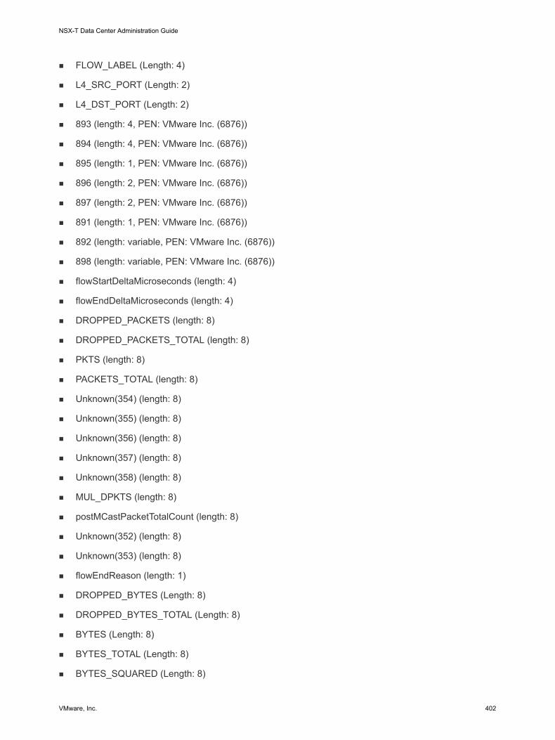
n FLOW_LABEL (Length: 4)
n L4_SRC_PORT (Length: 2)
n L4_DST_PORT (Length: 2)
n 893 (length: 4, PEN: VMware Inc. (6876))
n 894 (length: 4, PEN: VMware Inc. (6876))
n 895 (length: 1, PEN: VMware Inc. (6876))
n 896 (length: 2, PEN: VMware Inc. (6876))
n 897 (length: 2, PEN: VMware Inc. (6876))
n 891 (length: 1, PEN: VMware Inc. (6876))
n 892 (length: variable, PEN: VMware Inc. (6876))
n 898 (length: variable, PEN: VMware Inc. (6876))
n flowStartDeltaMicroseconds (length: 4)
n flowEndDeltaMicroseconds (length: 4)
n DROPPED_PACKETS (length: 8)
n DROPPED_PACKETS_TOTAL (length: 8)
n PKTS (length: 8)
n PACKETS_TOTAL (length: 8)
n Unknown(354) (length: 8)
n Unknown(355) (length: 8)
n Unknown(356) (length: 8)
n Unknown(357) (length: 8)
n Unknown(358) (length: 8)
n MUL_DPKTS (length: 8)
n postMCastPacketTotalCount (length: 8)
n Unknown(352) (length: 8)
n Unknown(353) (length: 8)
n flowEndReason (length: 1)
n DROPPED_BYTES (Length: 8)
n DROPPED_BYTES_TOTAL (Length: 8)
n BYTES (Length: 8)
n BYTES_TOTAL (Length: 8)
n BYTES_SQUARED (Length: 8)
NSX-T Data Center Administration Guide
VMware, Inc. 402

n BYTES_SQUARED_PERMANENT (Length: 8)
n IP LENGTH MINIMUM (Length: 8)
n IP LENGTH MAXIMUM (Length: 8)
n MUL_DOCTETS (Length: 8)
n postMCastOctetTotalCount (Length: 8)
n tcpAckTotalCount (Length: 8)
n tcpFinTotalCount (Length: 8)
n tcpPshTotalCount (Length: 8)
n tcpRstTotalCount (Length: 8)
n tcpSynTotalCount (Length: 8)
n tcpUrgTotalCount (Length: 8)
KVM UDP over IPv6 VLAN IPFIX TemplatesThere are four KVM UDP over IPv6 VLAN IPFIX templates: ingress, egress, ingress with tunnel, and egress with tunnel.
UDP over IPv6 VLAN Ingress
Template ID: 364. Field count: 51.
The fields are:
n observationPointId (length: 4)
n DIRECTION (length: 1)
n SRC_MAC (length: 6)
n DESTINATION_MAC (length: 6)
n ethernetType (length: 2)
n ethernetHeaderLength (length: 1)
n INPUT_SNMP (length: 4)
n Unknown(368) (length: 4)
n IF_NAME (length: variable)
n IF_DESC (length: variable)
n SRC_VLAN (Length: 2)
n dot1qVlanId (Length: 2)
n dot1qPriority (Length: 1)
n IP_PROTOCOL_VERSION (Length: 1)
NSX-T Data Center Administration Guide
VMware, Inc. 403

n IP_TTL (Length: 1)
n PROTOCOL (Length: 1)
n IP_DSCP (Length: 1)
n IP_PRECEDENCE (Length: 1)
n IP_TOS (Length: 1)
n IPV6_SRC_ADDR (Length: 4)
n IPV6_DST_ADDR (Length: 4)
n FLOW_LABEL (Length: 4)
n L4_SRC_PORT (Length: 2)
n L4_DST_PORT (Length: 2)
n 898 (length: variable, PEN: VMware Inc. (6876))
n flowStartDeltaMicroseconds (length: 4)
n flowEndDeltaMicroseconds (length: 4)
n DROPPED_PACKETS (length: 8)
n DROPPED_PACKETS_TOTAL (length: 8)
n PKTS (length: 8)
n PACKETS_TOTAL (length: 8)
n Unknown(354) (length: 8)
n Unknown(355) (length: 8)
n Unknown(356) (length: 8)
n Unknown(357) (length: 8)
n Unknown(358) (length: 8)
n MUL_DPKTS (length: 8)
n postMCastPacketTotalCount (length: 8)
n Unknown(352) (length: 8)
n Unknown(353) (length: 8)
n flowEndReason (length: 1)
n DROPPED_BYTES (Length: 8)
n DROPPED_BYTES_TOTAL (Length: 8)
n BYTES (Length: 8)
n BYTES_TOTAL (Length: 8)
n BYTES_SQUARED (Length: 8)
NSX-T Data Center Administration Guide
VMware, Inc. 404

n BYTES_SQUARED_PERMANENT (Length: 8)
n IP LENGTH MINIMUM (Length: 8)
n IP LENGTH MAXIMUM (Length: 8)
n MUL_DOCTETS (Length: 8)
n postMCastOctetTotalCount (Length: 8)
UDP over IPv6 VLAN Egress
Template ID: 365. Field count: 55.
The fields are:
n observationPointId (length: 4)
n DIRECTION (length: 1)
n SRC_MAC (length: 6)
n DESTINATION_MAC (length: 6)
n ethernetType (length: 2)
n ethernetHeaderLength (length: 1)
n INPUT_SNMP (length: 4)
n Unknown(368) (length: 4)
n IF_NAME (length: variable)
n IF_DESC (length: variable)
n OUTPUT_SNMP (Length: 4)
n Unknown(369) (Length: 4)
n IF_NAME (Length: variable)
n IF_DESC (Length: variable)
n SRC_VLAN (Length: 2)
n dot1qVlanId (Length: 2)
n dot1qPriority (Length: 1)
n IP_PROTOCOL_VERSION (Length: 1)
n IP_TTL (Length: 1)
n PROTOCOL (Length: 1)
n IP_DSCP (Length: 1)
n IP_PRECEDENCE (Length: 1)
n IP_TOS (Length: 1)
NSX-T Data Center Administration Guide
VMware, Inc. 405

n IPV6_SRC_ADDR (Length: 4)
n IPV6_DST_ADDR (Length: 4)
n FLOW_LABEL (Length: 4)
n L4_SRC_PORT (Length: 2)
n L4_DST_PORT (Length: 2)
n 898 (length: variable, PEN: VMware Inc. (6876))
n flowStartDeltaMicroseconds (length: 4)
n flowEndDeltaMicroseconds (length: 4)
n DROPPED_PACKETS (length: 8)
n DROPPED_PACKETS_TOTAL (length: 8)
n PKTS (length: 8)
n PACKETS_TOTAL (length: 8)
n Unknown(354) (length: 8)
n Unknown(355) (length: 8)
n Unknown(356) (length: 8)
n Unknown(357) (length: 8)
n Unknown(358) (length: 8)
n MUL_DPKTS (length: 8)
n postMCastPacketTotalCount (length: 8)
n Unknown(352) (length: 8)
n Unknown(353) (length: 8)
n flowEndReason (length: 1)
n DROPPED_BYTES (Length: 8)
n DROPPED_BYTES_TOTAL (Length: 8)
n BYTES (Length: 8)
n BYTES_TOTAL (Length: 8)
n BYTES_SQUARED (Length: 8)
n BYTES_SQUARED_PERMANENT (Length: 8)
n IP LENGTH MINIMUM (Length: 8)
n IP LENGTH MAXIMUM (Length: 8)
n MUL_DOCTETS (Length: 8)
n postMCastOctetTotalCount (Length: 8)
NSX-T Data Center Administration Guide
VMware, Inc. 406

UDP over IPv6 VLAN Ingress with Tunnel
Template ID: 366. Field count: 58.
The fields are:
n observationPointId (length: 4)
n DIRECTION (length: 1)
n SRC_MAC (length: 6)
n DESTINATION_MAC (length: 6)
n ethernetType (length: 2)
n ethernetHeaderLength (length: 1)
n INPUT_SNMP (length: 4)
n Unknown(368) (length: 4)
n IF_NAME (length: variable)
n IF_DESC (length: variable)
n SRC_VLAN (Length: 2)
n dot1qVlanId (Length: 2)
n dot1qPriority (Length: 1)
n IP_PROTOCOL_VERSION (Length: 1)
n IP_TTL (Length: 1)
n PROTOCOL (Length: 1)
n IP_DSCP (Length: 1)
n IP_PRECEDENCE (Length: 1)
n IP_TOS (Length: 1)
n IPV6_SRC_ADDR (Length: 4)
n IPV6_DST_ADDR (Length: 4)
n FLOW_LABEL (Length: 4)
n L4_SRC_PORT (Length: 2)
n L4_DST_PORT (Length: 2)
n 893 (length: 4, PEN: VMware Inc. (6876))
n 894 (length: 4, PEN: VMware Inc. (6876))
n 895 (length: 1, PEN: VMware Inc. (6876))
n 896 (length: 2, PEN: VMware Inc. (6876))
n 897 (length: 2, PEN: VMware Inc. (6876))
NSX-T Data Center Administration Guide
VMware, Inc. 407

n 891 (length: 1, PEN: VMware Inc. (6876))
n 892 (length: variable, PEN: VMware Inc. (6876))
n 898 (length: variable, PEN: VMware Inc. (6876))
n flowStartDeltaMicroseconds (length: 4)
n flowEndDeltaMicroseconds (length: 4)
n DROPPED_PACKETS (length: 8)
n DROPPED_PACKETS_TOTAL (length: 8)
n PKTS (length: 8)
n PACKETS_TOTAL (length: 8)
n Unknown(354) (length: 8)
n Unknown(355) (length: 8)
n Unknown(356) (length: 8)
n Unknown(357) (length: 8)
n Unknown(358) (length: 8)
n MUL_DPKTS (length: 8)
n postMCastPacketTotalCount (length: 8)
n Unknown(352) (length: 8)
n Unknown(353) (length: 8)
n flowEndReason (length: 1)
n DROPPED_BYTES (Length: 8)
n DROPPED_BYTES_TOTAL (Length: 8)
n BYTES (Length: 8)
n BYTES_TOTAL (Length: 8)
n BYTES_SQUARED (Length: 8)
n BYTES_SQUARED_PERMANENT (Length: 8)
n IP LENGTH MINIMUM (Length: 8)
n IP LENGTH MAXIMUM (Length: 8)
n MUL_DOCTETS (Length: 8)
n postMCastOctetTotalCount (Length: 8)
UDP over IPv6 VLAN Egress with Tunnel
Template ID: 367. Field count: 62.
NSX-T Data Center Administration Guide
VMware, Inc. 408

The fields are:
n observationPointId (length: 4)
n DIRECTION (length: 1)
n SRC_MAC (length: 6)
n DESTINATION_MAC (length: 6)
n ethernetType (length: 2)
n ethernetHeaderLength (length: 1)
n INPUT_SNMP (length: 4)
n Unknown(368) (length: 4)
n IF_NAME (length: variable)
n IF_DESC (length: variable)
n OUTPUT_SNMP (Length: 4)
n Unknown(369) (Length: 4)
n IF_NAME (Length: variable)
n IF_DESC (Length: variable)
n SRC_VLAN (Length: 2)
n dot1qVlanId (Length: 2)
n dot1qPriority (Length: 1)
n IP_PROTOCOL_VERSION (Length: 1)
n IP_TTL (Length: 1)
n PROTOCOL (Length: 1)
n IP_DSCP (Length: 1)
n IP_PRECEDENCE (Length: 1)
n IP_TOS (Length: 1)
n IPV6_SRC_ADDR (Length: 4)
n IPV6_DST_ADDR (Length: 4)
n FLOW_LABEL (Length: 4)
n L4_SRC_PORT (Length: 2)
n L4_DST_PORT (Length: 2)
n 893 (length: 4, PEN: VMware Inc. (6876))
n 894 (length: 4, PEN: VMware Inc. (6876))
n 895 (length: 1, PEN: VMware Inc. (6876))
NSX-T Data Center Administration Guide
VMware, Inc. 409

n 896 (length: 2, PEN: VMware Inc. (6876))
n 897 (length: 2, PEN: VMware Inc. (6876))
n 891 (length: 1, PEN: VMware Inc. (6876))
n 892 (length: variable, PEN: VMware Inc. (6876))
n 898 (length: variable, PEN: VMware Inc. (6876))
n flowStartDeltaMicroseconds (length: 4)
n flowEndDeltaMicroseconds (length: 4)
n DROPPED_PACKETS (length: 8)
n DROPPED_PACKETS_TOTAL (length: 8)
n PKTS (length: 8)
n PACKETS_TOTAL (length: 8)
n Unknown(354) (length: 8)
n Unknown(355) (length: 8)
n Unknown(356) (length: 8)
n Unknown(357) (length: 8)
n Unknown(358) (length: 8)
n MUL_DPKTS (length: 8)
n postMCastPacketTotalCount (length: 8)
n Unknown(352) (length: 8)
n Unknown(353) (length: 8)
n flowEndReason (length: 1)
n DROPPED_BYTES (Length: 8)
n DROPPED_BYTES_TOTAL (Length: 8)
n BYTES (Length: 8)
n BYTES_TOTAL (Length: 8)
n BYTES_SQUARED (Length: 8)
n BYTES_SQUARED_PERMANENT (Length: 8)
n IP LENGTH MINIMUM (Length: 8)
n IP LENGTH MAXIMUM (Length: 8)
n MUL_DOCTETS (Length: 8)
n postMCastOctetTotalCount (Length: 8)
NSX-T Data Center Administration Guide
VMware, Inc. 410

KVM SCTP over IPv6 VLAN IPFIX TemplatesThere are four KVM SCTP over IPv6 VLAN IPFIX templates: ingress, egress, ingress with tunnel, and egress with tunnel.
SCTP over IPv6 VLAN Ingress
Template ID: 368. Field count: 51.
The fields are:
n observationPointId (length: 4)
n DIRECTION (length: 1)
n SRC_MAC (length: 6)
n DESTINATION_MAC (length: 6)
n ethernetType (length: 2)
n ethernetHeaderLength (length: 1)
n INPUT_SNMP (length: 4)
n Unknown(368) (length: 4)
n IF_NAME (length: variable)
n IF_DESC (length: variable)
n SRC_VLAN (Length: 2)
n dot1qVlanId (Length: 2)
n dot1qPriority (Length: 1)
n IP_PROTOCOL_VERSION (Length: 1)
n IP_TTL (Length: 1)
n PROTOCOL (Length: 1)
n IP_DSCP (Length: 1)
n IP_PRECEDENCE (Length: 1)
n IP_TOS (Length: 1)
n IPV6_SRC_ADDR (Length: 4)
n IPV6_DST_ADDR (Length: 4)
n FLOW_LABEL (Length: 4)
n L4_SRC_PORT (Length: 2)
n L4_DST_PORT (Length: 2)
n 898 (length: variable, PEN: VMware Inc. (6876))
n flowStartDeltaMicroseconds (length: 4)
NSX-T Data Center Administration Guide
VMware, Inc. 411

n flowEndDeltaMicroseconds (length: 4)
n DROPPED_PACKETS (length: 8)
n DROPPED_PACKETS_TOTAL (length: 8)
n PKTS (length: 8)
n PACKETS_TOTAL (length: 8)
n Unknown(354) (length: 8)
n Unknown(355) (length: 8)
n Unknown(356) (length: 8)
n Unknown(357) (length: 8)
n Unknown(358) (length: 8)
n MUL_DPKTS (length: 8)
n postMCastPacketTotalCount (length: 8)
n Unknown(352) (length: 8)
n Unknown(353) (length: 8)
n flowEndReason (length: 1)
n DROPPED_BYTES (Length: 8)
n DROPPED_BYTES_TOTAL (Length: 8)
n BYTES (Length: 8)
n BYTES_TOTAL (Length: 8)
n BYTES_SQUARED (Length: 8)
n BYTES_SQUARED_PERMANENT (Length: 8)
n IP LENGTH MINIMUM (Length: 8)
n IP LENGTH MAXIMUM (Length: 8)
n MUL_DOCTETS (Length: 8)
n postMCastOctetTotalCount (Length: 8)
SCTP over IPv6 VLAN Egress
Template ID: 369. Field count: 55.
The fields are:
n observationPointId (length: 4)
n DIRECTION (length: 1)
n SRC_MAC (length: 6)
NSX-T Data Center Administration Guide
VMware, Inc. 412

n DESTINATION_MAC (length: 6)
n ethernetType (length: 2)
n ethernetHeaderLength (length: 1)
n INPUT_SNMP (length: 4)
n Unknown(368) (length: 4)
n IF_NAME (length: variable)
n IF_DESC (length: variable)
n OUTPUT_SNMP (Length: 4)
n Unknown(369) (Length: 4)
n IF_NAME (Length: variable)
n IF_DESC (Length: variable)
n SRC_VLAN (Length: 2)
n dot1qVlanId (Length: 2)
n dot1qPriority (Length: 1)
n IP_PROTOCOL_VERSION (Length: 1)
n IP_TTL (Length: 1)
n PROTOCOL (Length: 1)
n IP_DSCP (Length: 1)
n IP_PRECEDENCE (Length: 1)
n IP_TOS (Length: 1)
n IPV6_SRC_ADDR (Length: 4)
n IPV6_DST_ADDR (Length: 4)
n FLOW_LABEL (Length: 4)
n L4_SRC_PORT (Length: 2)
n L4_DST_PORT (Length: 2)
n 898 (length: variable, PEN: VMware Inc. (6876))
n flowStartDeltaMicroseconds (length: 4)
n flowEndDeltaMicroseconds (length: 4)
n DROPPED_PACKETS (length: 8)
n DROPPED_PACKETS_TOTAL (length: 8)
n PKTS (length: 8)
n PACKETS_TOTAL (length: 8)
NSX-T Data Center Administration Guide
VMware, Inc. 413

n Unknown(354) (length: 8)
n Unknown(355) (length: 8)
n Unknown(356) (length: 8)
n Unknown(357) (length: 8)
n Unknown(358) (length: 8)
n MUL_DPKTS (length: 8)
n postMCastPacketTotalCount (length: 8)
n Unknown(352) (length: 8)
n Unknown(353) (length: 8)
n flowEndReason (length: 1)
n DROPPED_BYTES (Length: 8)
n DROPPED_BYTES_TOTAL (Length: 8)
n BYTES (Length: 8)
n BYTES_TOTAL (Length: 8)
n BYTES_SQUARED (Length: 8)
n BYTES_SQUARED_PERMANENT (Length: 8)
n IP LENGTH MINIMUM (Length: 8)
n IP LENGTH MAXIMUM (Length: 8)
n MUL_DOCTETS (Length: 8)
n postMCastOctetTotalCount (Length: 8)
SCTP over IPv6 VLAN Ingress with Tunnel
Template ID: 370. Field count: 58.
The fields are:
n observationPointId (length: 4)
n DIRECTION (length: 1)
n SRC_MAC (length: 6)
n DESTINATION_MAC (length: 6)
n ethernetType (length: 2)
n ethernetHeaderLength (length: 1)
n INPUT_SNMP (length: 4)
n Unknown(368) (length: 4)
NSX-T Data Center Administration Guide
VMware, Inc. 414

n IF_NAME (length: variable)
n IF_DESC (length: variable)
n SRC_VLAN (Length: 2)
n dot1qVlanId (Length: 2)
n dot1qPriority (Length: 1)
n IP_PROTOCOL_VERSION (Length: 1)
n IP_TTL (Length: 1)
n PROTOCOL (Length: 1)
n IP_DSCP (Length: 1)
n IP_PRECEDENCE (Length: 1)
n IP_TOS (Length: 1)
n IPV6_SRC_ADDR (Length: 4)
n IPV6_DST_ADDR (Length: 4)
n FLOW_LABEL (Length: 4)
n L4_SRC_PORT (Length: 2)
n L4_DST_PORT (Length: 2)
n 893 (length: 4, PEN: VMware Inc. (6876))
n 894 (length: 4, PEN: VMware Inc. (6876))
n 895 (length: 1, PEN: VMware Inc. (6876))
n 896 (length: 2, PEN: VMware Inc. (6876))
n 897 (length: 2, PEN: VMware Inc. (6876))
n 891 (length: 1, PEN: VMware Inc. (6876))
n 892 (length: variable, PEN: VMware Inc. (6876))
n 898 (length: variable, PEN: VMware Inc. (6876))
n flowStartDeltaMicroseconds (length: 4)
n flowEndDeltaMicroseconds (length: 4)
n DROPPED_PACKETS (length: 8)
n DROPPED_PACKETS_TOTAL (length: 8)
n PKTS (length: 8)
n PACKETS_TOTAL (length: 8)
n Unknown(354) (length: 8)
n Unknown(355) (length: 8)
NSX-T Data Center Administration Guide
VMware, Inc. 415

n Unknown(356) (length: 8)
n Unknown(357) (length: 8)
n Unknown(358) (length: 8)
n MUL_DPKTS (length: 8)
n postMCastPacketTotalCount (length: 8)
n Unknown(352) (length: 8)
n Unknown(353) (length: 8)
n flowEndReason (length: 1)
n DROPPED_BYTES (Length: 8)
n DROPPED_BYTES_TOTAL (Length: 8)
n BYTES (Length: 8)
n BYTES_TOTAL (Length: 8)
n BYTES_SQUARED (Length: 8)
n BYTES_SQUARED_PERMANENT (Length: 8)
n IP LENGTH MINIMUM (Length: 8)
n IP LENGTH MAXIMUM (Length: 8)
n MUL_DOCTETS (Length: 8)
n postMCastOctetTotalCount (Length: 8)
SCTP over IPv6 VLAN Egress with Tunnel
Template ID: 371. Field count: 62.
The fields are:
n observationPointId (length: 4)
n DIRECTION (length: 1)
n SRC_MAC (length: 6)
n DESTINATION_MAC (length: 6)
n ethernetType (length: 2)
n ethernetHeaderLength (length: 1)
n INPUT_SNMP (length: 4)
n Unknown(368) (length: 4)
n IF_NAME (length: variable)
n IF_DESC (length: variable)
NSX-T Data Center Administration Guide
VMware, Inc. 416

n OUTPUT_SNMP (Length: 4)
n Unknown(369) (Length: 4)
n IF_NAME (Length: variable)
n IF_DESC (Length: variable)
n SRC_VLAN (Length: 2)
n dot1qVlanId (Length: 2)
n dot1qPriority (Length: 1)
n IP_PROTOCOL_VERSION (Length: 1)
n IP_TTL (Length: 1)
n PROTOCOL (Length: 1)
n IP_DSCP (Length: 1)
n IP_PRECEDENCE (Length: 1)
n IP_TOS (Length: 1)
n IPV6_SRC_ADDR (Length: 4)
n IPV6_DST_ADDR (Length: 4)
n FLOW_LABEL (Length: 4)
n L4_SRC_PORT (Length: 2)
n L4_DST_PORT (Length: 2)
n 893 (length: 4, PEN: VMware Inc. (6876))
n 894 (length: 4, PEN: VMware Inc. (6876))
n 895 (length: 1, PEN: VMware Inc. (6876))
n 896 (length: 2, PEN: VMware Inc. (6876))
n 897 (length: 2, PEN: VMware Inc. (6876))
n 891 (length: 1, PEN: VMware Inc. (6876))
n 892 (length: variable, PEN: VMware Inc. (6876))
n 898 (length: variable, PEN: VMware Inc. (6876))
n flowStartDeltaMicroseconds (length: 4)
n flowEndDeltaMicroseconds (length: 4)
n DROPPED_PACKETS (length: 8)
n DROPPED_PACKETS_TOTAL (length: 8)
n PKTS (length: 8)
n PACKETS_TOTAL (length: 8)
NSX-T Data Center Administration Guide
VMware, Inc. 417

n Unknown(354) (length: 8)
n Unknown(355) (length: 8)
n Unknown(356) (length: 8)
n Unknown(357) (length: 8)
n Unknown(358) (length: 8)
n MUL_DPKTS (length: 8)
n postMCastPacketTotalCount (length: 8)
n Unknown(352) (length: 8)
n Unknown(353) (length: 8)
n flowEndReason (length: 1)
n DROPPED_BYTES (Length: 8)
n DROPPED_BYTES_TOTAL (Length: 8)
n BYTES (Length: 8)
n BYTES_TOTAL (Length: 8)
n BYTES_SQUARED (Length: 8)
n BYTES_SQUARED_PERMANENT (Length: 8)
n IP LENGTH MINIMUM (Length: 8)
n IP LENGTH MAXIMUM (Length: 8)
n MUL_DOCTETS (Length: 8)
n postMCastOctetTotalCount (Length: 8)
KVM ICMPv6 VLAN IPFIX TemplatesThere are four KVM ICMPv6 IPFIX templates: ingress, egress, ingress with tunnel, and egress with tunnel.
ICMPv6 Ingress
Template ID: 372. Field count: 51.
The fields are:
n observationPointId (length: 4)
n DIRECTION (length: 1)
n SRC_MAC (length: 6)
n DESTINATION_MAC (length: 6)
n ethernetType (length: 2)
NSX-T Data Center Administration Guide
VMware, Inc. 418

n ethernetHeaderLength (length: 1)
n INPUT_SNMP (length: 4)
n Unknown(368) (length: 4)
n IF_NAME (length: variable)
n IF_DESC (length: variable)
n SRC_VLAN (Length: 2)
n dot1qVlanId (Length: 2)
n dot1qPriority (Length: 1)
n IP_PROTOCOL_VERSION (Length: 1)
n IP_TTL (Length: 1)
n PROTOCOL (Length: 1)
n IP_DSCP (Length: 1)
n IP_PRECEDENCE (Length: 1)
n IP_TOS (Length: 1)
n IPV6_SRC_ADDR (Length: 4)
n IPV6_DST_ADDR (Length: 4)
n FLOW_LABEL (Length: 4)
n ICMP_IPv6_TYPE (Length: 1)
n ICMP_IPv6_CODE (Length: 1)
n 898 (length: variable, PEN: VMware Inc. (6876))
n flowStartDeltaMicroseconds (length: 4)
n flowEndDeltaMicroseconds (length: 4)
n DROPPED_PACKETS (length: 8)
n DROPPED_PACKETS_TOTAL (length: 8)
n PKTS (length: 8)
n PACKETS_TOTAL (length: 8)
n Unknown(354) (length: 8)
n Unknown(355) (length: 8)
n Unknown(356) (length: 8)
n Unknown(357) (length: 8)
n Unknown(358) (length: 8)
n MUL_DPKTS (length: 8)
NSX-T Data Center Administration Guide
VMware, Inc. 419

n postMCastPacketTotalCount (length: 8)
n Unknown(352) (length: 8)
n Unknown(353) (length: 8)
n flowEndReason (length: 1)
n DROPPED_BYTES (Length: 8)
n DROPPED_BYTES_TOTAL (Length: 8)
n BYTES (Length: 8)
n BYTES_TOTAL (Length: 8)
n BYTES_SQUARED (Length: 8)
n BYTES_SQUARED_PERMANENT (Length: 8)
n IP LENGTH MINIMUM (Length: 8)
n IP LENGTH MAXIMUM (Length: 8)
n MUL_DOCTETS (Length: 8)
n postMCastOctetTotalCount (Length: 8)
ICMPv6 Egress
Template ID: 373. Field count: 55.
The fields are:
n observationPointId (length: 4)
n DIRECTION (length: 1)
n SRC_MAC (length: 6)
n DESTINATION_MAC (length: 6)
n ethernetType (length: 2)
n ethernetHeaderLength (length: 1)
n INPUT_SNMP (length: 4)
n Unknown(368) (length: 4)
n IF_NAME (length: variable)
n IF_DESC (length: variable)
n OUTPUT_SNMP (Length: 4)
n Unknown(369) (Length: 4)
n IF_NAME (Length: variable)
n IF_DESC (Length: variable)
NSX-T Data Center Administration Guide
VMware, Inc. 420

n SRC_VLAN (Length: 2)
n dot1qVlanId (Length: 2)
n dot1qPriority (Length: 1)
n IP_PROTOCOL_VERSION (Length: 1)
n IP_TTL (Length: 1)
n PROTOCOL (Length: 1)
n IP_DSCP (Length: 1)
n IP_PRECEDENCE (Length: 1)
n IP_TOS (Length: 1)
n IPV6_SRC_ADDR (Length: 4)
n IPV6_DST_ADDR (Length: 4)
n FLOW_LABEL (Length: 4)
n ICMP_IPv6_TYPE (Length: 1)
n ICMP_IPv6_CODE (Length: 1)
n 898 (length: variable, PEN: VMware Inc. (6876))
n flowStartDeltaMicroseconds (length: 4)
n flowEndDeltaMicroseconds (length: 4)
n DROPPED_PACKETS (length: 8)
n DROPPED_PACKETS_TOTAL (length: 8)
n PKTS (length: 8)
n PACKETS_TOTAL (length: 8)
n Unknown(354) (length: 8)
n Unknown(355) (length: 8)
n Unknown(356) (length: 8)
n Unknown(357) (length: 8)
n Unknown(358) (length: 8)
n MUL_DPKTS (length: 8)
n postMCastPacketTotalCount (length: 8)
n Unknown(352) (length: 8)
n Unknown(353) (length: 8)
n flowEndReason (length: 1)
n DROPPED_BYTES (Length: 8)
NSX-T Data Center Administration Guide
VMware, Inc. 421

n DROPPED_BYTES_TOTAL (Length: 8)
n BYTES (Length: 8)
n BYTES_TOTAL (Length: 8)
n BYTES_SQUARED (Length: 8)
n BYTES_SQUARED_PERMANENT (Length: 8)
n IP LENGTH MINIMUM (Length: 8)
n IP LENGTH MAXIMUM (Length: 8)
n MUL_DOCTETS (Length: 8)
n postMCastOctetTotalCount (Length: 8)
ICMPv6 Ingress with Tunnel
Template ID: 374. Field count: 58.
The fields are:
n observationPointId (length: 4)
n DIRECTION (length: 1)
n SRC_MAC (length: 6)
n DESTINATION_MAC (length: 6)
n ethernetType (length: 2)
n ethernetHeaderLength (length: 1)
n INPUT_SNMP (length: 4)
n Unknown(368) (length: 4)
n IF_NAME (length: variable)
n IF_DESC (length: variable)
n SRC_VLAN (Length: 2)
n dot1qVlanId (Length: 2)
n dot1qPriority (Length: 1)
n IP_PROTOCOL_VERSION (Length: 1)
n IP_TTL (Length: 1)
n PROTOCOL (Length: 1)
n IP_DSCP (Length: 1)
n IP_PRECEDENCE (Length: 1)
n IP_TOS (Length: 1)
NSX-T Data Center Administration Guide
VMware, Inc. 422

n IPV6_SRC_ADDR (Length: 4)
n IPV6_DST_ADDR (Length: 4)
n FLOW_LABEL (Length: 4)
n ICMP_IPv6_TYPE (Length: 1)
n ICMP_IPv6_CODE (Length: 1)
n 893 (length: 4, PEN: VMware Inc. (6876))
n 894 (length: 4, PEN: VMware Inc. (6876))
n 895 (length: 1, PEN: VMware Inc. (6876))
n 896 (length: 2, PEN: VMware Inc. (6876))
n 897 (length: 2, PEN: VMware Inc. (6876))
n 891 (length: 1, PEN: VMware Inc. (6876))
n 892 (length: variable, PEN: VMware Inc. (6876))
n 898 (length: variable, PEN: VMware Inc. (6876))
n flowStartDeltaMicroseconds (length: 4)
n flowEndDeltaMicroseconds (length: 4)
n DROPPED_PACKETS (length: 8)
n DROPPED_PACKETS_TOTAL (length: 8)
n PKTS (length: 8)
n PACKETS_TOTAL (length: 8)
n Unknown(354) (length: 8)
n Unknown(355) (length: 8)
n Unknown(356) (length: 8)
n Unknown(357) (length: 8)
n Unknown(358) (length: 8)
n MUL_DPKTS (length: 8)
n postMCastPacketTotalCount (length: 8)
n Unknown(352) (length: 8)
n Unknown(353) (length: 8)
n flowEndReason (length: 1)
n DROPPED_BYTES (Length: 8)
n DROPPED_BYTES_TOTAL (Length: 8)
n BYTES (Length: 8)
NSX-T Data Center Administration Guide
VMware, Inc. 423

n BYTES_TOTAL (Length: 8)
n BYTES_SQUARED (Length: 8)
n BYTES_SQUARED_PERMANENT (Length: 8)
n IP LENGTH MINIMUM (Length: 8)
n IP LENGTH MAXIMUM (Length: 8)
n MUL_DOCTETS (Length: 8)
n postMCastOctetTotalCount (Length: 8)
ICMPv6 Egress with Tunnel
Template ID: 375. Field count: 62.
The fields are:
n observationPointId (length: 4)
n DIRECTION (length: 1)
n SRC_MAC (length: 6)
n DESTINATION_MAC (length: 6)
n ethernetType (length: 2)
n ethernetHeaderLength (length: 1)
n INPUT_SNMP (length: 4)
n Unknown(368) (length: 4)
n IF_NAME (length: variable)
n IF_DESC (length: variable)
n OUTPUT_SNMP (Length: 4)
n Unknown(369) (Length: 4)
n IF_NAME (Length: variable)
n IF_DESC (Length: variable)
n SRC_VLAN (Length: 2)
n dot1qVlanId (Length: 2)
n dot1qPriority (Length: 1)
n IP_PROTOCOL_VERSION (Length: 1)
n IP_TTL (Length: 1)
n PROTOCOL (Length: 1)
n IP_DSCP (Length: 1)
NSX-T Data Center Administration Guide
VMware, Inc. 424

n IP_PRECEDENCE (Length: 1)
n IP_TOS (Length: 1)
n IPV6_SRC_ADDR (Length: 4)
n IPV6_DST_ADDR (Length: 4)
n FLOW_LABEL (Length: 4)
n ICMP_IPv6_TYPE (Length: 1)
n ICMP_IPv6_CODE (Length: 1)
n 893 (length: 4, PEN: VMware Inc. (6876))
n 894 (length: 4, PEN: VMware Inc. (6876))
n 895 (length: 1, PEN: VMware Inc. (6876))
n 896 (length: 2, PEN: VMware Inc. (6876))
n 897 (length: 2, PEN: VMware Inc. (6876))
n 891 (length: 1, PEN: VMware Inc. (6876))
n 892 (length: variable, PEN: VMware Inc. (6876))
n 898 (length: variable, PEN: VMware Inc. (6876))
n flowStartDeltaMicroseconds (length: 4)
n flowEndDeltaMicroseconds (length: 4)
n DROPPED_PACKETS (length: 8)
n DROPPED_PACKETS_TOTAL (length: 8)
n PKTS (length: 8)
n PACKETS_TOTAL (length: 8)
n Unknown(354) (length: 8)
n Unknown(355) (length: 8)
n Unknown(356) (length: 8)
n Unknown(357) (length: 8)
n Unknown(358) (length: 8)
n MUL_DPKTS (length: 8)
n postMCastPacketTotalCount (length: 8)
n Unknown(352) (length: 8)
n Unknown(353) (length: 8)
n flowEndReason (length: 1)
n DROPPED_BYTES (Length: 8)
NSX-T Data Center Administration Guide
VMware, Inc. 425

n DROPPED_BYTES_TOTAL (Length: 8)
n BYTES (Length: 8)
n BYTES_TOTAL (Length: 8)
n BYTES_SQUARED (Length: 8)
n BYTES_SQUARED_PERMANENT (Length: 8)
n IP LENGTH MINIMUM (Length: 8)
n IP LENGTH MAXIMUM (Length: 8)
n MUL_DOCTETS (Length: 8)
n postMCastOctetTotalCount (Length: 8)
KVM Options IPFIX TemplatesThere is one KVM options template, based on IETF RFC 7011, section 3.4.2.
Options Template
Template ID: 462. Scope count: 1. Data count: 1.
Trace the Path of a Packet with TraceflowUse Traceflow to inspect the path of a packet as it travels from one logical port on the logical network to another logical port on the same network. Traceflow traces the transport node-level path of a packet injected at a logical port. The trace packet traverses the logical switch overlay, but is not visible to interfaces attached to the logical switch. In other words, no packet is actually delivered to the test packet’s intended recipients.
Procedure
1 From your browser, log in with admin privileges to an NSX Manager at https://nsx-manager-ip-address.
2 Navigate to the Traceflow screen. You have two options.
n Select Tools > Traceflow from the navigation panel.
n Select Switching from the navigation panel, click the Ports tab, select a VIF-attached port and click Actions > Traceflow
3 Select a traffic type.
The choices are Unicast, Multicast, and Broadcast.
NSX-T Data Center Administration Guide
VMware, Inc. 426

4 Specify the source and destination information according to the traffic type.
Traffic Type Specify Source Information Specify Destination Information
Unicast Select a VM and a virtual interface.
The IP address and MAC address are displayed if VMtools is installed in the VM or if the VM is deployed using OpenStack plug-in (address bindings will be used in this case). If the VM has more than one IP address, select one from the drop-down menu.
If the IP address and MAC address are not displayed, enter the IP address and MAC address in the text boxes.
This will also apply to Multicast and Broadcast.
Select either VM Name or IP-MAC from the "Type" drop-down menu.
n If VM Name is selected, select a VM and virtual interface. Select or enter an IP address and a MAC address
n If IP-MAC is selected, select the trace type (Layer 2 or layer 3). If trace type is Layer 2, enter an IP address and a MAC address. If trace type is Layer 3, enter an IP address.
Multicast Same as above. Enter an IP Address. It must be a multicast address from 224.0.0.0 - 239.255.255.255.
Broadcast Same as above. Enter a subnet prefix length.
5 (Optional) Click Advanced to see the advanced options.
6 (Optional) In the left column, enter the desired values or input for the following fields:
Option Description
Frame Size e.g. 128
TTL e.g. 64
Timeout (ms) e.g. 10000
Ethertype e.g. 2048
Payload Type Select an option from the dropdown menu.
Payload Data Payload formatted based on selected Payload Type (Base64, Hex, Plaintext, Binary, or Decimal)
7 (Optional) In the left column under "Protocol", select a protocol from the "Type" drop-down menu.
8 (Optional) Based on the protocol selected, complete the associated steps in the following table.
Protocol Step 1 Step 2 Step 3
TCP Enter a source port. Enter a destination port. Select the desired TCP Flags from the drop-down menu.
UDP Enter a source port. Enter a destination port. N/A
ICMP Enter an ICMP ID. Enter a sequence value. N/A
9 Click Trace.
Information about the connections, components, and layers is displayed. The output includes a table listing Observation Type (Delivered, Dropped, Received, Forwarded), Transport Node, and Component, and a graphical map of the topology if unicast and logical switch as a destination are
NSX-T Data Center Administration Guide
VMware, Inc. 427

selected. You can apply a filter (All, Delivered, Dropped) on the observations that are displayed. If there are dropped observations, the Dropped filter is applied by default. Otherwise, the All filter is applied. The graphical map shows the backplane and router links. Note that bridging information is not displayed.
View Port Connection InformationYou can use the port connection tool to quickly visualize and troubleshoot the connection between two VMs.
Procedure
1 From your browser, log in with admin privileges to an NSX Manager at https://nsx-manager-ip-address.
2 Select Tools > Port Connection from the navigation panel.
3 Select a VM from the Source Virtual Machine drop-down menu.
4 Select a VM from the Destination Virtual Machine drop-down menu.
5 Click Go.
A visual map of the port connection topology is displayed. You can click on any of the components in the visual output to reveal more information about that component.
Monitor a Logical Switch Port ActivityYou can monitor the logical port activity for example, to troubleshoot network congestion and packets being dropped
Prerequisites
Verify that a logical switch port is configured. See Connecting a VM to a Logical Switch.
Procedure
1 From your browser, log in with admin privileges to an NSX Manager at https://nsx-manager-ip-address.
2 Select Networking > Switching from the navigation panel.
3 Click the Ports tab.
4 Click the name of a port.
5 Click the Monitor tab.
The port status and statistics are displayed.
6 To download a CSV file of the MAC addresses that has been learned by the host, click Download MAC Table.
NSX-T Data Center Administration Guide
VMware, Inc. 428

7 To monitor activity on the port, click Begin Tracking.
A port tracking page opens. You can view the bidirectional port traffic and identify dropped packets. The port tracker page also lists the switching profiles attached to the logical switch port.
If you notice dropped packets because of network congestion, you can configure a QoS switching profile for the logical switch port to prevent data loss on preferred packets. See Understanding QoS Switching Profile.
Monitor Port Mirroring SessionsYou can monitor port mirroring sessions for troubleshooting and other purposes.
NSX Cloud Note If using NSX Cloud, see How to use NSX-T Data Center Features with the Public Cloud for a list of auto-generated logical entities, supported features, and configurations required for NSX Cloud.
This feature has the following restrictions:
n A source mirror port cannot be in more than one mirror session.
n A destination port can only receive mirror traffic.
n With KVM, multiple NICs can be attached to the same OVS port. The mirroring happens at the OVS uplink port, meaning that traffic on all the pNICs attached to the OVS port is mirrored.
n Mirror session source and destination ports must be on the same host vSwitch. Therefore, if you vMotion the VM that has the source or destination port to another host, traffic on that port can no longer be mirrored.
n On ESXi, when mirroring is enabled on the uplink, raw production TCP packets are encapsulated using the Geneve protocol by VDL2 into UDP packets. A physical NIC that supports TSO (TCP segmentation offload) can change the packets and mark the packets with the MUST_TSO flag. On a monitor VM with VMXNET3 or E1000 vNICs, the driver treats the packets as regular UDP packets and cannot handle the MUST_TSO flag, and will drop the packets.
If a lot of traffic is mirrored to a monitor VM, there is a potential for the driver's buffer ring to become full and packets to be dropped. To alleviate the problem, you can take one or more of the following actions:
n Increase the rx buffer ring size.
n Assign more CPU resources to the VM.
NSX-T Data Center Administration Guide
VMware, Inc. 429

n Use the Data Plane Development Kit (DPDK) to improve packet processing performance.
Note Make sure that the monitor VM's MTU setting (in the case of KVM, the hypervisor's virtual NIC device's MTU setting also) is large enough to handle the packets. This is especially important for encapsulated packets because encapsulation increases the size of packets. Otherwise, packets might be dropped. This is not an issue with ESXi VMs with VMXNET3 NICs, but is a potential issue with other types of NICs on both ESXi and KVM VMs.
Note In an L3 port mirroring session involving VMs on KVM hosts, you must set the MTU size to be large enough to handle the extra bytes required by encapsulation. The mirror traffic goes through an OVS interface and OVS uplink. You must set the OVS interface's MTU to be at least 100 bytes larger than the size of the original packet (before encapsulation and mirroring). If you see dropped packets, increase the MTU setting for the host's virtual NIC and the OVS interface. Use the following command to set the MTU for an OVS interface:
ovs-vsctl -- set interface <ovs_Interface> mtu_request=<MTU>
Note When you monitor the logical port of a VM and the uplink port of a host where the VM resides, you will see different behaviors depending on whether the host is ESXi or KVM. For ESXi, the logical-port mirror packets and the uplink mirror packets are tagged with the same VLAN ID and appear the same to the monitor VM. For KVM, the logical-port mirror packets are not tagged with a VLAN ID but the uplink mirror packets are tagged, and they appear different to the monitor VM.
Procedure
1 From your browser, log in with admin privileges to an NSX Manager at https://nsx-manager-ip-address.
2 Select Tools > Port Mirroring Session from the navigation panel.
3 Click Add and select a session type.
The available types are Local SPAN, Remote SPAN, Remote L3 SPAN, and Logical SPAN.
4 Enter a session name and optionally a description.
5 Provide additional parameters.
Session Type Parameters
Local SPAN n Transport Node - Select a transport node.
n Direction - Select Bidirectional, Ingress, or Egress.
n Packet Truncation - Select a packet truncation value.
Remote SPAN n Session Type - Select RSPAN Source session or RSPAN Destination session.
n Transport Node - Select a transport node.
n Direction - Select Bidirectional, Ingress, or Egress.
n Packet Truncation - Select a packet truncation value.
n Encap. VLAN ID - Specify an encapsulation VLAN ID.
n Preserve Orig. VLAN - Select whether to preserve the original VLAN ID.
NSX-T Data Center Administration Guide
VMware, Inc. 430

Session Type Parameters
Remote L3 SPAN n Encapsulation - Select GRE, ERSPAN TWO, or ERSPAN THREE.
n GRE Key - Specify a GRE key if encapsulation is GRE.
n Transport Node - Specify a transport node if encapsulation is ERSPAN TWO or ERSPAN THREE.
n ERSPAN ID - Specify an ERSPAN ID if encapsulation is ERSPAN TWO or ERSPAN THREE.
n Direction - Select Bidirectional, Ingress, or Egress.
n Packet Truncation - Select a packet truncation value.
Logical SPAN n Logical Switch - Select a logical switch.
n Direction - Select Bidirectional, Ingress, or Egress.
n Packet Truncation - Select a packet truncation value.
6 Click Next.
7 Provide source information.
Session Type Parameters
Local SPAN n Select an N-VDS.
n Select physical interfaces.
n Enable or disable encapsulated packet.
n Select virtual machines.
n Select virtual interfaces.
Remote SPAN n Select virtual machines.
n Select virtual interfaces.
Remote L3 SPAN n Select virtual machines.
n Select virtual interfaces.
n Select a logical switch.
Logical SPAN n Select logical ports.
8 Click Next.
9 Provide destination information.
Session Type Parameters
Local SPAN n Select virtual machines.
n Select virtual interfaces.
Remote SPAN n Select an N-VDS.
n Select physical interfaces.
Remote L3 SPAN n Specify an IPv4 address.
Logical SPAN n Select logical ports.
10 Click Save.
You cannot change the source or destination after saving the port mirroring session.
NSX-T Data Center Administration Guide
VMware, Inc. 431

Monitor Fabric NodesYou can monitor fabric nodes such as hosts, edges, NSX Edge clusters, bridges, and transport nodes from the NSX Manager UI.
Procedure
1 From your browser, log in with admin privileges to an NSX Manager at https://nsx-manager-ip-address.
2 Select Fabric > Nodes from the navigation panel.
3 Select one of the following tabs.
n Hosts
n Edges
n Edge Clusters
n Bridges
n Transport Nodes
Note On the Hosts screen, if the MPA Connectivity status is Down or Unknown for a host, ignore the LCP Connectivity status because it might be inaccurate.
View Data about Applications Running on VMsYou can view information about applications running on VMs that are members of an NSGroup. This is a technical preview feature.
Procedure
1 From your browser, log in with admin privileges to an NSX Manager at https://nsx-manager-ip-address.
2 Select Inventory > Groups from the navigation panel.
3 Click the name of an NSGroup.
4 Click the Applications tab.
5 Click COLLECT APPLICATION DATA.
This process can take a few minutes. When the process is completed, the following information is displayed:
n The total number of processes.
n Circles representing various tiers, for example, web tier, database tier, and application tier. Also displayed is the number of processes in each tier.
6 Click a circle to see more information about the processes in that tier.
NSX-T Data Center Administration Guide
VMware, Inc. 432

Collecting Support BundlesYou can collect support bundles on registered cluster and fabric nodes and download the bundles to your machine or upload them to a file server.
If you choose to download the bundles to your machine, you get a single archive file consisting of a manifest file and support bundles for each node. If you choose to upload the bundles to a file server, the manifest file and the individual bundles are uploaded to the file server separately.
NSX Cloud Note If you want to collect the support bundle for CSM, log in to CSM, go to System > Utilities > Support Bundle and click on Download. The support bundle for PCG is available from NSX Manager using the following instructions. The support bundle for PCG also contains logs for all the workload VMs.
Procedure
1 From your browser, log in with admin privileges to NSX Manager at https://nsx-manager-ip-address.
2 Select System > Utilities from the navigation panel.
3 Click the Support Bundle tab.
4 Select the target nodes.
The available types of nodes are Management Nodes, Controller Nodes, Edges, Hosts, and Public Cloud Gateways.
5 (Optional) Specify log age in days to exclude logs that are older than the specified number of days.
6 (Optional) Toggle the switch that indicates whether to include or exclude core files and audit logs.
Note Core files and audit logs might contain sensitive information such as passwords or encryption keys.
7 (Optional) Select a check box to upload the bundles to a file server.
8 Click Start Bundle Collection to start collecting support bundles.
Depending on how many log files exist, each node might take several minutes.
9 Monitor the status of the collection process.
The status field shows the percentage of nodes that completed support bundle collection.
10 Click Download to download the bundle if the option to send the bundle to a file server was not set.
Customer Experience Improvement ProgramNSX-T Data Center participates in VMware’s Customer Experience Improvement Program (CEIP).
Details regarding the data collected through CEIP and the purposes for which it is used by VMware are set forth at the Trust & Assurance Center at https://www.vmware.com/solutions/trustvmware/ceip.html.
NSX-T Data Center Administration Guide
VMware, Inc. 433

To join or leave the CEIP for NSX-T Data Center, or edit program settings, see Edit the Customer Experience Improvement Program Configuration.
Edit the Customer Experience Improvement Program ConfigurationWhen you install or upgrade NSX Manager, you can decide to join the CEIP and configure data collection settings.
You can also edit the existing CEIP configuration to join or leave the program, define the frequency and the days the information is collected, and proxy server configuration.
Prerequisites
n Verify that the NSX Manager is connected and can synchronize with your hypervisor.
n Verify that NSX-T Data Center is connected to a public network for uploading data.
Procedure
1 From your browser, log in with admin privileges to an NSX Manager at https://nsx-manager-ip-address.
2 Select System > Configuration > Properties.
3 Click Edit in the Status and Statistics section.
4 Toggle the Data Collection menu item.
5 Click Edit in the Customer Experience Improvement Program section.
6 Toggle the Join the VMware Customer Experience Improvement Program menu item.
7 (Optional) Configure the data collection and upload recurrence settings.
8 (Optional) Click the Proxy tab.
9 Toggle the Proxy menu item to configure proxy server settings to send data.
Option Description
Host Name Enter the proxy server FQDN or IP address.
Port Enter the proxy server port.
Username (Optional) Enter the user name used to authenticate with the proxy server.
Password (Optional) Enter the password used to authenticate with the proxy server.
Scheme Set either the HTTP or HTTPS scheme accepted by the proxy server from the drop-down menu.
10 Click Save.
NSX-T Data Center Administration Guide
VMware, Inc. 434


