13
ADITYA KUMAR 12BEE0003 SELECT OCTOBER, 2014 BARH SUPER THERMAL POWER PLANT ,BIHAR TIME PERIOD(01-6-2014 – 30-06-2014) INTERNSHIP PRESENTATION ON NTPC BARH VIT UNIVERSITY
| Date post: | 20-Aug-2015 |
| Category: |
Education |
| Upload: | aditya-empire |
| View: | 787 times |
| Download: | 1 times |

ADITYA KUMAR 12BEE0003
SELECT
OCTOBER, 2014
BARH SUPER THERMAL POWER PLANT ,BIHARTIME PERIOD(01-6-2014 – 30-06-2014)
INTERNSHIP PRESENTATIONON
NTPC BARH
VIT UNIVERSITY

NTPC Overview NTPC Limited (Formerly National Thermal Power Corporation) is the
largest power generation company in India and was founded on November 7, 1975. Forbes Global 2000 for 2009 ranked it 317th in the world.
Contributing 26% of country’s entire power generation, it has placed itself in the Nav - Ratan companies of Indian government and hence is the public sector company.
The total installed capacity of the company is 31134 MW (including JVs) with 15 coal based and 7 gas based stations, located across the country. In addition under JVs, 3 stations are coal based & another station uses naphtha/LNG as fuel.
NTPC has been operating its plants at high efficiency levels. Although the company has 18.79% of the total national capacity it contributes 28.60% of total power generation due to its focus on high efficiency.
The company has set a future goal of having 75000 MW by 2017.

BSTPP AT GLANCENo. of units × capacity : 3× 660MW(STAGE -I) 2× 660MW(STAGE -II) 1,2 and 3 : Russian origin 4 and 5: under the collaboration of BHEL and ALSTOM Boilers and Turbines: Manufactured by BHEL and ALSTOM Generators: Supplied by SIEMENSCoal supply: Hazaribagh coal mines. Coal requirement for the project in estimated as 10 million tones/annum considering a GCV of 3350 kcal/kg and 80% PLF.Water requirement: - The project site is located near the river Ganga. The make up water requirement for the project is proposed to be drawn from river Ganga.Plant has two stages: Stage 1 – voltage generation-24.5kv Stage 2 – voltage generation-215kvLand requirement: Approximately 1200 acres of land has been identified between NH-1 and railway lines for the plant area, switchyard, green belt, labour colony, ash based units and township.approximately 1750 acres of land has been identified for the ash disposal area in the south of railway line. Location: The project site is located about 3kms east of Barh town in Patna district in the state of Bihar, having a latitude and longitude of 25 deg 28' N and 85deg 45' E respectively. The plant and township are located between NH-31 and railway line. The ash disposal area is located in the south of the railway line.

Power plant familiarization Coal before fixing in the furnace is
Pulverized.coal pulverization is required in the whole system process not just in terms of furnace performance and heat rate but in terms of mechanical reliability and integrity of furnace.
Flame is established in the furnace Using the LDO(light diesel oil).LDO is atomized by applying arc to it.
Coal+air- Co2+CO+Sox+MOx+heat+ASH Here CO2-heat carrier CO-Acidic, danger to tubes(less air) MOX,SOX-Acidic formation in water bodies and atmosphere.
To avoid the gases CO,MOX,SOX a ratio is maintained between air and coal of 1:6.It also ensures proper combustion.The water is purified(DM water) before injunction in the furnace to prevent choking of pipes due to the scale formation.

IMPORTANT VARIOUS PARTS OF BSTPP
1.BOILER2.TURBINES3.COOLING WATER PUMP4.CONDENSER5.DEAREATOR6.REHEATER7.AIR PREHEATER8.PRECIPITATOR9.ECONOMISER10.COOLING TOWER11.TRANSMISSION LINES(3 PHASE)12.UNIT TRANSFORMERS(3 PHASE)13.ELECTRIC GENERATORS(3 PHASE)14.CONDENSATE EXTRACTION PUMP
15. Steam governor valve 16. FEED HEATER17.COAL CONVEYOR18.COAL HOPPER19.FORCED DRAUGHT FAN20.FLUE GAS

1.BoilerBoiler is a rectangular furnace about 50 feet on side and 130 feet tall. theirs walls are made of high pressure steel tubes about 2.3 inches in diameter which circulates DM water to be converted into steam. The thermal radiation heats water and changes to steam. Steam is sent to the turbine .The efficiency and technology of boiler vary according to the operational pressures.1. Operational pressure>221 KSC---%n=42.45%-----super critical boiler2. 175KSC <Operational pressure<221 KSC---%n=38.42%----- critical boiler3. Operational pressure<175KSC---%n=38%-----sub critical boiler
The turbine generator consists of a series of steam turbines interconnected to each other and generators on a common shaft. There is a high pressure turbine at one end, followed by intermediate pressure turbine and low pressure turbine in other end. Steam loses pressure and temperatures as it passes through turbines and expands in volume.
2.Turbines
3.Cooling water pumpsIt pumps the water from the cooling tower which goes to the condenser.
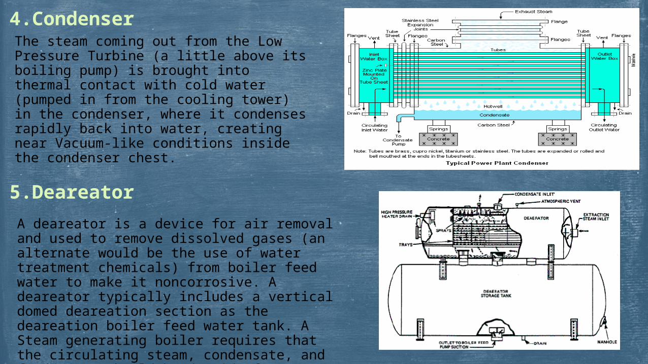
4.CondenserThe steam coming out from the Low Pressure Turbine (a little above its boiling pump) is brought into thermal contact with cold water (pumped in from the cooling tower) in the condenser, where it condenses rapidly back into water, creating near Vacuum-like conditions inside the condenser chest.
5.Deareator
A deareator is a device for air removal and used to remove dissolved gases (an alternate would be the use of water treatment chemicals) from boiler feed water to make it noncorrosive. A deareator typically includes a vertical domed deareation section as the deareation boiler feed water tank. A Steam generating boiler requires that the circulating steam, condensate, and feed water should be devoid of dissolved gases, particularly corrosive ones and dissolved or suspended solids. The gases will give rise to corrosion of the metal.

6.ReheaterReheater is a heater which is used to raise the temperature of steam which has fallen from the intermediate pressure turbine.
7.Air preheaterAir preheater is a general term to describe any device designed to heat air before another process (for example, combustion in a boiler). The purpose of the air preheater is to recover the heat from the boiler flue gas which increases the thermal efficiency of the boiler by reducing the useful heat lost in the flue gas.
8.PrecipitatorAn Electrostatic precipitator (ESP) or electrostatic air cleaner is a particulate device that removes particles from a flowing gas (such as air) using the force of an induced electrostatic charge. Electrostatic precipitators are highly efficient filtration devices, and can easily remove fine particulate matter such as dust and smoke from the air steam. ESPs continue to be excellent devices for control of many industrial particulate emissions
ELECTRICAL OVERVIEW General Voltage Level LT – 415 V HT – 11KV & 3.3 KV EHT – 400KV Voltage generation level (NTPC Barh) stage 1 – 24.5kv stage 2 – 21.5kv voltage level ( power plant) 5.5kv, 11kv, 132kv,400kv

Switch YardSwitchyard is considered as the HEART of the Power Plant. Power generated can be worthy only if it is successfully transmitted and received by its consumers. Switchyard plays a very important role as a junction between the generation and transmission. It is a junction, which carries the generated power to its destination (i.e. consumers).
Outdoor equipments
1. Bus bar2. Lightening Arrester3. Wavetrap 4. Breaker5. Capacitive voltage transformer6. Earthingrod 7. Current transformer8. Potential transformer9. Lightening Mask
Indoor equipments
1. Relays2. Control panels’3. Circuit breakers
In BSTPP there are two switchyards:- (i) 400KV SWITCHYARD (ii) 132KV SWITCHYARD
.400 KV SWITCHYARD There are total 22 bay in 400 KV switchyard. A Bay is basically a way for the incoming power from generator as well as outgoing power for distribution. 5 Bay for each generating transformer 3 Bay for ICT(Inter Connecting Transformer) 2 Bay for PATNA line 2 Bay for KAHALGAON line 2 Bay for BALIA line 7 for FUTURE line 1 Bay for SHUNT REACTOR
There are four main buses in 400 KV switchyard. Main bus – 1& 2 Main bus – 3&4
132 KV SWITCHYARD There are total 11 Bay in 132 KV switchyard. 3 Bay for ICT (Inter Connecting Transformer) 5 Bay for S.T (Station Transformer) 2 Bay for MST (Miscellaneous Service Transformer) 1 Bay for Bus Coupler
There are two main buses in 132 KV switchyard. Main bus - 1 Main bus - 2

TRANSFORMERSIt is a static machine which increases or decreases the AC voltage without changing the frequency of the supply. It is a device that: Transfers electric power from one circuit to another. It accomplishes this by electromagnetic induction. In this the two electric circuits are in mutual inductive influence of each other.
WORKING PRINCIPLE: It works on FARADAY‟S LAW OF ELECTROMAGNETIC INDUCTION (self or mutual induction depending on the type of transformer).
CLASSIFICATION:
(I) ACCORDING TO THE CORE: a) Core type transformer b) shell type transformer c) Berry type transformer (II) ACCORDING TO PHASES: a) 1phase transformer b) 3phase transformer (III) ACCORDING TO THE PURPOSE FOR WHICH USED : a) Distribution transformer b) Transmission transformer c) Generator transformer d) Station transformer e) Unit Auxiliary transformer (UAT)

GENERATOR SPECIFICATIONS-
KVA 247000 Pf 0.85 Volts of stator 15750 Amperes of stator 9050 Volts of rotor 310 Amperes of rotor 2600 Rpm 3000 Hz 50 Phase 3 Connection YY Coolant water(stator)&hydrogen(rotor)Gas pressure 3.5kg/cm-sq.Insulation class B
Turbo generators are used in thermal power stations because of the steam energy to mechanical energy conversion, turbo generators are more efficient.
GENERATOR


