25
NTSB Board Meeting AA Flight 587 Airplane Motion and Vertical Stabilizer Loads John O’Callaghan
| Date post: | 30-Dec-2015 |
| Category: |
Documents |
| Upload: | meagan-barnett |
| View: | 214 times |
| Download: | 0 times |
NTSB Board MeetingAA Flight 587NTSB Board MeetingAA Flight 587
Airplane Motion and Vertical Stabilizer LoadsAirplane Motion and Vertical Stabilizer Loads
John O’CallaghanJohn O’Callaghan

-1.0 -0.5 0.0 0.5 1.0 1.5 2.0 2.5 3.0 3.5 4.0
-0.5
0.0
0.5
1.0
1.5
2.0
2.5
3.0
3.5
4.0
4.5
0915:51 Start of second wake turbulence encounter
0915:36 Start of first wake turbulence encounter
Dis
tanc
e no
rth
of im
pact
site
, nm
Distance east of impact site, nm
31L
Bo
ein
g 7
47
Flig
ht 5
87
WIND
Location of Wake Turbulence Encounters
• FDR accelerations were typical of wake encounters
• Crew commented on wake turbulence
• Simulation indicates wake encounter
• NASA wake study supports encounter
• Wake was similar in each encounter

NTSB Board Meeting AA Flight 587
NTSB Board Meeting AA Flight 587
Effect of the Wake Encounters on the Airplane
Motion
Effect of the Wake Encounters on the Airplane
Motion• NASA study indicates nothing unusual about
wake.
• NTSB simulations determined that the effect of wake on airplane motion was minor.
• The airplane was not in or at risk of an upset.
• NASA study indicates nothing unusual about wake.
• NTSB simulations determined that the effect of wake on airplane motion was minor.
• The airplane was not in or at risk of an upset.

Control Inputs Following Start of First Wake Encounter
• First officer responded with column & large wheel inputs
• First officer did not use the rudder pedals
• Small changes in pitch and roll angles
• Airplane motion was unremarkable
09:15:34 09:15:36 09:15:38 09:15:40 09:15:42 09:15:44
100
50
0
-50
-100
09:15:34 09:15:36 09:15:38 09:15:40 09:15:42 09:15:44
3
2
1
0
-1
-2
-3
09:15:34 09:15:36 09:15:38 09:15:40 09:15:42 09:15:44
-10
-5
0
5
10
FWD COLUMN
AFT COLUMN
RIGHT WHEEL
RIGHT PEDAL
LEFT PEDAL
Co
lum
n, d
egre
es
LEFT WHEEL
Wh
eel,
deg
rees
Ped
al, i
nch
es
ATC Time, HH:MM:SS ESTTime

Time = 09:15:51
Control Inputs Following Start of Second Wake Encounter
• Start of second wake encounter
• Airplane in climbing left turn
• Controls approximately neutral
09:15:50 09:15:52 09:15:54 09:15:56 09:15:58
100
50
0
-50
-100
09:15:50 09:15:52 09:15:54 09:15:56 09:15:58
3
2
1
0
-1
-2
-3
09:15:50 09:15:52 09:15:54 09:15:56 09:15:58
-10
-5
0
5
10
FWD COLUMN
AFT COLUMN
RIGHT WHEEL
RIGHT PEDAL
LEFT PEDAL
Co
lum
n, d
egre
es
LEFT WHEEL
Wh
eel,
deg
rees
Ped
al, i
nch
es
ATC Time, HH:MM:SS ESTTime

Control Inputs Following Start of Second Wake Encounter
Time = 09:15:52
• Pedal used to help control roll • Pedal not necessary
• Large right wheel input
• Full right pedal input
• Wheel alone sufficient to control roll
• Full wheel and pedal inputs unnecessary and excessive
09:15:50 09:15:52 09:15:54 09:15:56 09:15:58
100
50
0
-50
-100
09:15:50 09:15:52 09:15:54 09:15:56 09:15:58
3
2
1
0
-1
-2
-3
09:15:50 09:15:52 09:15:54 09:15:56 09:15:58
-10
-5
0
5
10
FWD COLUMN
AFT COLUMN
RIGHT WHEEL
RIGHT PEDAL
LEFT PEDAL
Co
lum
n, d
egre
es
LEFT WHEEL
Wh
eel,
deg
rees
Ped
al, i
nch
es
ATC Time, HH:MM:SS ESTTime

Time = 09:15:53.1
Control Inputs Following Start of Second Wake Encounter
First full alternating rudder pedal input
• Full left wheel input (78°)
• Full left pedal input
09:15:50 09:15:52 09:15:54 09:15:56 09:15:58
100
50
0
-50
-100
09:15:50 09:15:52 09:15:54 09:15:56 09:15:58
3
2
1
0
-1
-2
-3
09:15:50 09:15:52 09:15:54 09:15:56 09:15:58
-10
-5
0
5
10
FWD COLUMN
AFT COLUMN
RIGHT WHEEL
RIGHT PEDAL
LEFT PEDAL
Co
lum
n, d
egre
es
LEFT WHEEL
Wh
eel,
deg
rees
Ped
al, i
nch
es
ATC Time, HH:MM:SS ESTTime

Time = 09:15:54.2
Control Inputs Following Start of Second Wake Encounter
Second full alternating rudder pedal input
• Full right pedal input
• Growing oscillation in column inputs
09:15:50 09:15:52 09:15:54 09:15:56 09:15:58
100
50
0
-50
-100
09:15:50 09:15:52 09:15:54 09:15:56 09:15:58
3
2
1
0
-1
-2
-3
09:15:50 09:15:52 09:15:54 09:15:56 09:15:58
-10
-5
0
5
10
FWD COLUMN
AFT COLUMN
RIGHT WHEEL
RIGHT PEDAL
LEFT PEDAL
Co
lum
n, d
egre
es
LEFT WHEEL
Wh
eel,
deg
rees
Ped
al, i
nch
es
ATC Time, HH:MM:SS ESTTime

Time = 09:15:55.6
Control Inputs Following Start of Second Wake Encounter
• Full right pedal input maintained
• Wheel moves to large right deflection
• Large nose-down column input
09:15:50 09:15:52 09:15:54 09:15:56 09:15:58
100
50
0
-50
-100
09:15:50 09:15:52 09:15:54 09:15:56 09:15:58
3
2
1
0
-1
-2
-3
09:15:50 09:15:52 09:15:54 09:15:56 09:15:58
-10
-5
0
5
10
FWD COLUMN
AFT COLUMN
RIGHT WHEEL
RIGHT PEDAL
LEFT PEDAL
Co
lum
n, d
egre
es
LEFT WHEEL
Wh
eel,
deg
rees
Ped
al, i
nch
es
ATC Time, HH:MM:SS ESTTime
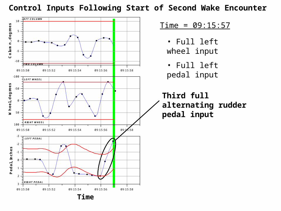
Time = 09:15:57
Control Inputs Following Start of Second Wake Encounter
Third full alternating rudder pedal input
• Full left wheel input
• Full left pedal input
09:15:50 09:15:52 09:15:54 09:15:56 09:15:58
100
50
0
-50
-100
09:15:50 09:15:52 09:15:54 09:15:56 09:15:58
3
2
1
0
-1
-2
-3
09:15:50 09:15:52 09:15:54 09:15:56 09:15:58
-10
-5
0
5
10
FWD COLUMN
AFT COLUMN
RIGHT WHEEL
RIGHT PEDAL
LEFT PEDAL
Co
lum
n, d
egre
es
LEFT WHEEL
Wh
eel,
deg
rees
Ped
al, i
nch
es
ATC Time, HH:MM:SS ESTTime

Time = 09:15:58.4
Control Inputs Following Start of Second Wake Encounter
Fourth full alternating rudder pedal input
• Wheel moves right
• Full right pedal input
• Vertical stabilizer separates from airplane
09:15:50 09:15:52 09:15:54 09:15:56 09:15:58
100
50
0
-50
-100
09:15:50 09:15:52 09:15:54 09:15:56 09:15:58
3
2
1
0
-1
-2
-3
09:15:50 09:15:52 09:15:54 09:15:56 09:15:58
-10
-5
0
5
10
FWD COLUMN
AFT COLUMN
RIGHT WHEEL
RIGHT PEDAL
LEFT PEDAL
Co
lum
n, d
egre
es
LEFT WHEEL
Wh
eel,
deg
rees
Ped
al, i
nch
es
ATC Time, HH:MM:SS ESTTime

09:15:50 09:15:52 09:15:54 09:15:56 09:15:58 09:16:00
-10
-5
0
5
10
NOSE RIGHT OF AIRFLOW
NOSE LEFT OF AIRFLOW
Sid
eslip
ang
le, d
egre
es
Airflow
Airflow
Sideslip Angle
Sideslip Angle Buildup Resulting From First Officer’s Control Inputs
• Airplane flew as commanded until vertical stabilizer separation
Vert
ical sta
b.
sep
ara
tion

NTSB Board Meeting AA Flight 587
NTSB Board Meeting AA Flight 587
Calculation of Vertical Stabilizer Loads
Calculation of Vertical Stabilizer Loads
• Loads dependent on airspeed, sideslip angle, and rudder deflection
• Aerodynamic loads determined by wind tunnel testing during airplane development
• No wind tunnel data available at the extreme sideslip angle corresponding to vertical stabilizer separation
• Other methods required to compute loads at time of separation
NTSB Board Meeting AA Flight 587
NTSB Board Meeting AA Flight 587
Computational Fluid Dynamics (CFD)
Computational Fluid Dynamics (CFD)
• CFD is the use of computers to mathematically determine the aerodynamic characteristics of airplanes.
• CFD is used increasingly in the industry to supplement wind tunnel data and optimize airplane designs.
• CFD is the use of computers to mathematically determine the aerodynamic characteristics of airplanes.
• CFD is used increasingly in the industry to supplement wind tunnel data and optimize airplane designs.
NTSB Board Meeting AA Flight 587
NTSB Board Meeting AA Flight 587
Computational Fluid Dynamics (CFD)
Computational Fluid Dynamics (CFD)
• CFD studies directed by NTSB and reviewed by NASA Langley Research Center.
• CFD studies directed by NTSB and reviewed by NASA Langley Research Center.
• CFD is the use of computers to mathematically determine the aerodynamic characteristics of airplanes.
• CFD is used increasingly in the industry to supplement wind tunnel data and optimize airplane designs.
• Airbus CFD code has demonstrated capability for solving flow problems such as flight 587 vertical stabilizer loads.

CFD Results: Pressure Distribution Over Vertical Stabilizer
Chordwise Distance (mm)
Pre
ssur
e C
oeffi
cien
t

Left Side Right Side
Flow Separation
CFD Results: Streamlines of Flow at High Sideslip Angle

09:15:50 09:15:52 09:15:54 09:15:56 09:15:58 09:16:00
-2.5
-2.0
-1.5
-1.0
-0.5
0.0
0.5
1.0
1.5
2.0
2.5
0r LIN38
TAIL BENDS RIGHT
TAIL BENDS LEFT
Time
Bending Moment History During Second Wake Encounter
Limit Load
Ultimate Load (1.5 x Limit)
Ultimate Load (1.5 x Limit)
Be
nd
ing
Mo
me
nt
/ Lim
it L
oa
d
Limit Load

Base ofVertical Stabilizer
Base ofVertical Stabilizer
Bending MomentBending Moment

09:15:50 09:15:52 09:15:54 09:15:56 09:15:58 09:16:00
-2.5
-2.0
-1.5
-1.0
-0.5
0.0
0.5
1.0
1.5
2.0
2.5
0r LIN38
TAIL BENDS RIGHT
TAIL BENDS LEFT
Time
Limit Load
Ultimate Load (1.5 x Limit)
Ultimate Load (1.5 x Limit)
Be
nd
ing
Mo
me
nt
/ Lim
it L
oa
d
Limit Load
Bending Moment History During Second Wake Encounter
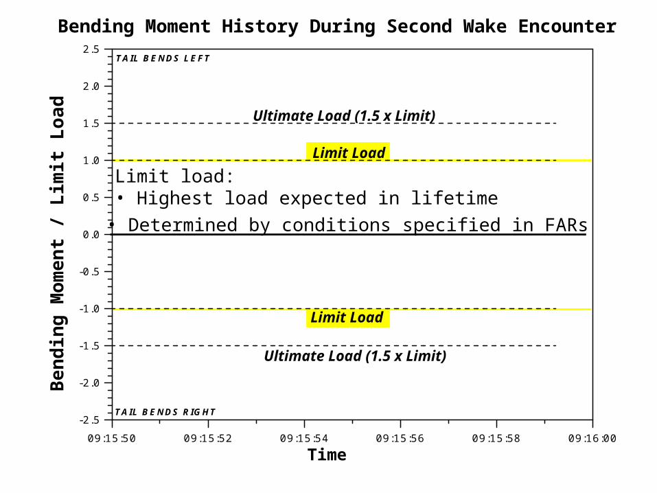
Limit load: • Highest load expected in lifetime
Time
Ultimate Load (1.5 x Limit)
Ultimate Load (1.5 x Limit)
Be
nd
ing
Mo
me
nt
/ Lim
it L
oa
d
Limit Load
• Determined by conditions specified in FARs
Limit Load
09:15:50 09:15:52 09:15:54 09:15:56 09:15:58 09:16:00
-2.5
-2.0
-1.5
-1.0
-0.5
0.0
0.5
1.0
1.5
2.0
2.5
0r LIN38
TAIL BENDS RIGHT
TAIL BENDS LEFT
Bending Moment History During Second Wake Encounter

Ultimate load: • Equal to limit load times safety factor of 1.5
Time
Limit Load
Ultimate Load (1.5 x Limit)
Ultimate Load (1.5 x Limit)
Be
nd
ing
Mo
me
nt
/ Lim
it L
oa
d
Limit Load
• Structure must not break up to ultimate load
Bending Moment History During Second Wake Encounter
09:15:50 09:15:52 09:15:54 09:15:56 09:15:58 09:16:00
-2.5
-2.0
-1.5
-1.0
-0.5
0.0
0.5
1.0
1.5
2.0
2.5
0r LIN38
TAIL BENDS RIGHT
TAIL BENDS LEFT

09:15:50 09:15:52 09:15:54 09:15:56 09:15:58 09:16:00-2.5
-2.0
-1.5
-1.0
-0.5
0.0
0.5
1.0
1.5
2.0
2.5
TAIL BENDS RIGHT
TAIL BENDS LEFT
Time
Limit Load
Ultimate Load (1.5 x Limit)
Ultimate Load (1.5 x Limit)
Be
nd
ing
Mo
me
nt
/ Lim
it L
oa
d
Limit Load
Wind tunnel analysisWind tunnel analysis
Range of loads at separation based on wind tunnel & CFD analysis
Range of loads at separation based on wind tunnel & CFD analysis
Bending Moment History During Second Wake Encounter

NTSB Board Meeting AA Flight 587
NTSB Board Meeting AA Flight 587
ConclusionsConclusionsAirplane encountered wake turbulence twice
• Indicated by FDR, CVR, simulation, and wake analysis
First officer’s control inputs following second encounter were unnecessary and excessive
• Simulation indicates wake had minor effect on motion
• Airplane was never in an upset condition
Airplane responded to control inputs as expected until vertical stabilizer separation
• Simulation indicates large sideslip angles were the result of control inputs
Vertical stabilizer separated at a bending moment load well above ultimate load
• Determined by wind tunnel and CFD analysis
Airplane encountered wake turbulence twice
• Indicated by FDR, CVR, simulation, and wake analysis
First officer’s control inputs following second encounter were unnecessary and excessive
• Simulation indicates wake had minor effect on motion
• Airplane was never in an upset condition
Airplane responded to control inputs as expected until vertical stabilizer separation
• Simulation indicates large sideslip angles were the result of control inputs
Vertical stabilizer separated at a bending moment load well above ultimate load
• Determined by wind tunnel and CFD analysis

National Transportation Safety BoardNational Transportation Safety Board
American Airlines Flight 587Belle Harbor, New YorkNovember 12, 2001
NTSB Board MeetingOctober 26, 2004
American Airlines Flight 587Belle Harbor, New YorkNovember 12, 2001
NTSB Board MeetingOctober 26, 2004


