Hsin-Chen Chen, Student Member, IEEE, and Yao-Wen Chang, Member, IEEE
Abstract—In addition to wirelength, modern placers need toconsider various constraints such as preplaced blocks and den-sity. We propose a high-quality analytical placement algorithmconsidering wirelength, preplaced blocks, and density based onthe log-sum-exp wirelength model proposed by Naylor et al. andthe multilevel framework. To handle preplaced blocks, we use atwo-stage smoothing technique, i.e., Gaussian smoothing followedby level smoothing, to facilitate block spreading during globalplacement (GP). The density is controlled by white-space reallo-cation using partitioning and cut-line shifting during GP and cellsliding during detailed placement. We further use the conjugategradient method with dynamic step-size control to speed up the GPand macro shifting to find better macro positions. Experimentalresults show that our placer obtains very high-quality results.
Index Terms—Legalization (LG), physical design, placement.
I. INTRODUCTION
A S process technology advances, the feature size is gettingsmaller and smaller. As a result, billions of transistors can
be integrated in a single chip. Meanwhile, the intellectual prop-erty modules and predesigned macro blocks (such as embeddedmemories, analog blocks, predesigned datapaths, etc.) are oftenreused. As a result, modern advanced IC designs often containmillions of standard cells and hundreds of macros with differentsizes. Hence, modern placers need to handle the instances withlarge-scale mixed-size macros and standard cells.
Manuscript received September 17, 2006; revised August 18, 2007. Thiswork was supported in part by MediaTek Inc., National Science Council ofTaiwan, R.O.C., under Grant NSC 94-2215-E-002-030 and Grant NSC 94-2752-E-002-008-PAE, and in part by RealTek Semiconductor Corporation.This paper was recommended by Associate Editor C. J. Alpert.
T.-C. Chen is with the Graduate Institute of Electronic Engineering, NationalTaiwan University, Taipei 106, Taiwan, R.O.C. He is also with SpringSoft, Inc.,Hsinchu 300, Taiwan, R.O.C. (e-mail: [email protected]).
Z.-W. Jiang is with the Graduate Institute of Electronic Engineering, Na-tional Taiwan University, Taipei 106, Taiwan, R.O.C. (e-mail: [email protected]).
T.-C. Hsu was with the Graduate Institute of Electronic Engineering, Na-tional Taiwan University, Taipei 106, Taiwan, R.O.C. He is now with SynopsysTaiwan Ltd., Taipei 110, Taiwan, R.O.C. (e-mail: [email protected]).
H.-C. Chen was with the Department of Electrical Engineering, NationalTaiwan University, Taipei 106, Taiwan, R.O.C. He is currently serving in themilitary in Taiwan, R.O.C. (e-mail: [email protected]).
Y.-W. Chang is with the Department of Electrical Engineering and GraduateInstitute of Electronics Engineering, National Taiwan University, Taipei 106,Taiwan, R.O.C., and also with Waseda University, Tokyo 169-8050, Japan(e-mail: [email protected]).
Color versions of one or more of the figures in this paper are available onlineat http://ieeexplore.ieee.org.
Digital Object Identifier 10.1109/TCAD.2008.923063
In addition, high-performance IC designs usually require sig-nificant white space for further performance optimization, suchas buffer insertion and gate sizing. Therefore, density controland white-space allocation (WSA) have become very impor-tant. A wirelength-driven placer without considering placementdensity tends to pack blocks together to minimize wirelength.However, an overcongested region may not have enough whitespace for buffer insertion and thus degrade the chip perfor-mance. Although some congestion-aware placement algorithmswere proposed [3], [4], these algorithms intend to minimize therouting congestion, which is different from the density controlsince the density can still be high for some regions even if norouting overflows occur in those regions.
Further, modern chip designs often consist of many pre-placed blocks, such as analog blocks, memory blocks, and/orI/O buffers, which are fixed in the chip and cannot overlap withother blocks. These preplaced blocks impose more constraintson the placement problem. A placement algorithm withoutconsidering preplaced blocks may generate illegal placementor inferior solutions.
Most of the recently proposed placement algorithms canhandle the mixed-size constraints [5]–[11]. However, very fewmodern mixed-size placement algorithms can satisfactorilyhandle preplaced blocks and the chip density. In this paper,we present a high-quality mixed-size analytical placement algo-rithm considering preplaced blocks and density constraints. Ourplacer is based on a three-stage technique: 1) global placement(GP); 2) legalization (LG); and 3) detailed placement (DP). Ithas the following distinguished features.
1) Based on the log-sum-exp wirelength model1 proposedby Naylor et al. [2] and the multilevel framework,our placer consistently generates high-quality mixed-sizeplacement results.
2) To solve the unconstrained minimization placement prob-lem, we use the conjugate gradient (CG) method withdynamic step sizes. Experimental results show that themethod leads to significant run-time speedups.
3) Our placer handles preplaced blocks by a two-stagesmoothing technique. The preplaced block potential isfirst smoothed by a Gaussian function to remove therugged potential regions, and then the potential levels are
1The log-sum-exp wirelength model is a patented technology [2], and userequires a license from Synopsys.
CHEN et al.: NTUplace3: ANALYTICAL PLACER FOR LARGE-SCALE MIXED-SIZE DESIGNS 1229
TABLE ICOMPARISONS BETWEEN OUR PLACER AND APLACE AND mPL; ALL THE PLACERS ARE BASED ON THE ANALYTICAL TECHNIQUE AND THE
LOG-SUM-EXP WIRELENGTH MODEL. UNKNOWN: NOT MENTIONED IN THE CORRESPONDING WORK
smoothed so that movable blocks can effectively spreadto the whole placement region.
4) Density constraints are considered during both GP andDP. We reallocate the white space using partitioning andcut-line shifting to remove density overflows betweendifferent levels of GP. In DP, a cell-sliding technique isapplied to reduce the density overflow.
5) A macro shifting technique is used between levels of GPto find better macro positions that are easier for LG.
6) A look-ahead LG scheme during GP is used to obtaina better legal placement result. The legalizer is calledseveral times near the end of GP. This technique canreduce the gap between GP and LG.
Table I summarizes the comparisons between our placer andtwo state-of-the-art analytical placers, i.e., APlace 2.0/3.0 [12],[13] and mPL5/6 [6], [14], which are also based on the log-sum-exp wirelength model. In the table, “Unknown” denotes that thecorresponding method is not available in the literature.
The remainder of this paper is organized as follows.Section II gives the analytical model used in our placer.Our core placement techniques are explained in Section III.Section IV reports the experimental results. Finally, the con-clusions are given in Section V.
II. ANALYTICAL PLACEMENT MODEL
The circuit placement problem can be formulated as ahypergraph H = (V,E) placement problem. Let the verticesV = {v1, v2, . . . , vn} represent blocks and the hyperedges E ={e1, e2, . . . , em} represent nets. Let xi and yi be the x and ycoordinates of the center of block vi, and let ai be the area ofthe block vi. The circuit may contain some preplaced blocksthat have fixed x and y coordinates and cannot be moved. Weintend to determine the optimal positions of movable blocks sothat the total wirelength is minimized and there is no overlapamong blocks. The placement problem is usually solved inthree stages: 1) GP; 2) LG; and 3) DP. GP evenly distributes theblocks and finds the best position for each block to minimize thetarget cost (e.g., wirelength). Then, LG removes all overlaps.Finally, DP refines the solution.
Fig. 1 shows the notation used in this paper.
Fig. 1. Notation used in this paper.
To evenly distribute the blocks, we divide the placementregion into uniform nonoverlapping bin grids. Then, the GPproblem can be formulated as a constrained minimization prob-lem as follows:
min W (x,y)
s.t. Db(x,y) ≤ Mb, for each bin b (1)
where W (x,y) is the wirelength function, Db(x,y) is thepotential function that is the total area of movable blocks inbin b, and Mb is the maximum allowable area of movable blocksin bin b. Mb can be computed by
Mb = tdensity(wbhb − Pb) (2)
where tdensity is a user-specified target density value for eachbin, wb (hb) is the width (height) of bin b, and Pb is the basepotential that equals the preplaced block area in bin b. Note thatMb is a fixed value as long as all preplaced block positions aregiven and the bin size is determined.
The wirelength W (x,y) is defined as the total half-perimeterwirelength (HPWL)
W (x,y) =∑net e
(max
vi,vj∈e|xi − xj | + max
vi,vj∈e|yi − yj |
). (3)
Since W (x,y) is not smooth and nonconvex, it is hard todirectly minimize it. Thus, several smooth wirelength approx-imation functions are proposed, such as quadratic wirelength
1230 IEEE TRANSACTIONS ON COMPUTER-AIDED DESIGN OF INTEGRATED CIRCUITS AND SYSTEMS, VOL. 27, NO. 7, JULY 2008
[15], [16], Lp-norm wirelength [13], [14], and log-sum-expwirelength [2], [5], [6]. The log-sum-exp wirelength model
γ∑e∈E
((log
∑vk∈e
exp(xk/γ) + log∑vk∈e
exp(−xk/γ)
+ log∑vk∈e
exp(yk/γ) + log∑vk∈e
exp(−yk/γ)
)(4)
proposed in [2] achieves the best result among these threemodels [14]. When γ is small, the log-sum-exp wirelength isclose to the HPWL [2]. However, due to the computer precision,we can only choose a reasonably small γ, for example, 1%long of the chip width, so that it will not cause any arithmeticoverflow.
Since the density Db(x,y) is neither smooth nor differen-tiable, mPL [14] uses inverse Laplace transformation to smooththe density, whereas APlace [5] uses a bell-shaped functionfor each block to smooth the density. We express the functionDb(x,y) as
Db(x,y) =∑v∈V
Px(b, v)Py(b, v) (5)
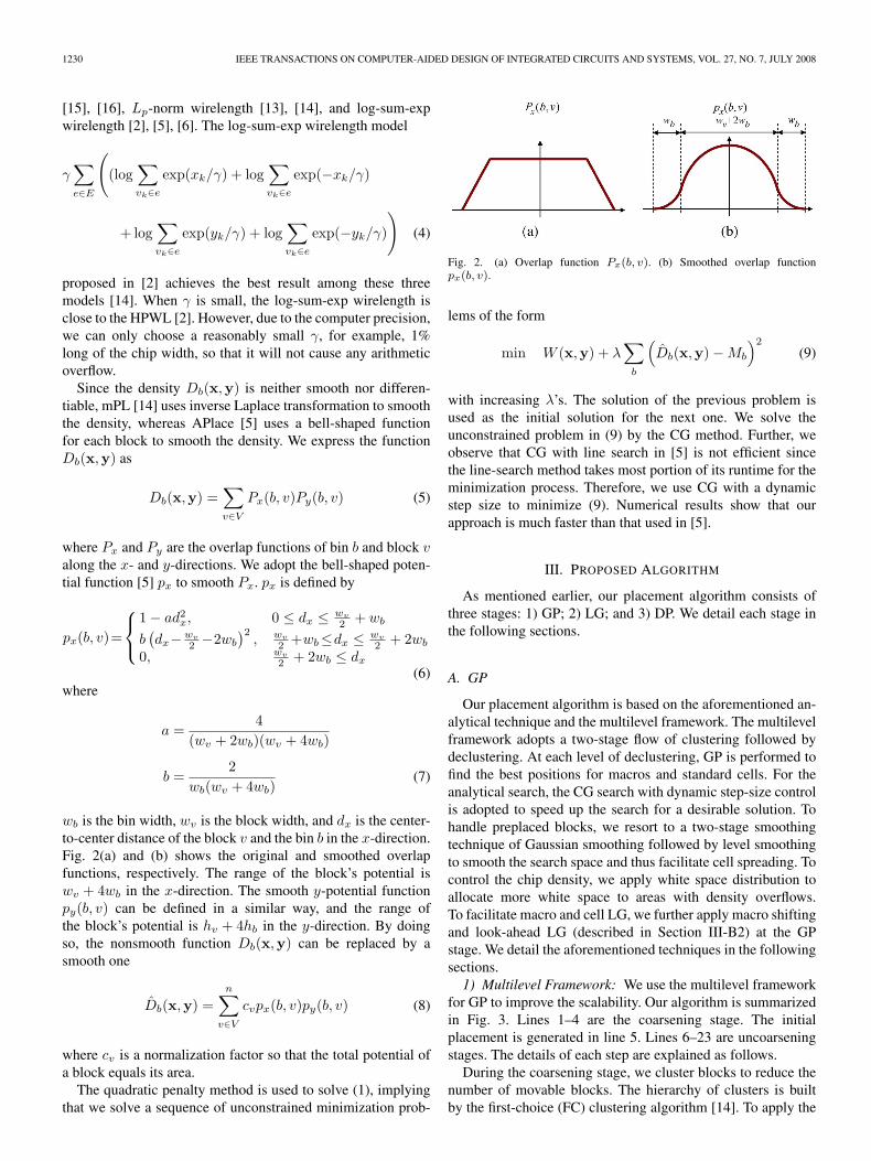
where Px and Py are the overlap functions of bin b and block valong the x- and y-directions. We adopt the bell-shaped poten-tial function [5] px to smooth Px. px is defined by
px(b, v)=
1 − ad2x, 0 ≤ dx ≤ wv
2 + wb
b(dx− wv
2 −2wb
)2, wv
2 +wb≤dx ≤ wv
2 + 2wb
0, wv
2 + 2wb ≤ dx
(6)where
a =4
(wv + 2wb)(wv + 4wb)
b =2
wb(wv + 4wb)(7)
wb is the bin width, wv is the block width, and dx is the center-to-center distance of the block v and the bin b in the x-direction.Fig. 2(a) and (b) shows the original and smoothed overlapfunctions, respectively. The range of the block’s potential iswv + 4wb in the x-direction. The smooth y-potential functionpy(b, v) can be defined in a similar way, and the range ofthe block’s potential is hv + 4hb in the y-direction. By doingso, the nonsmooth function Db(x,y) can be replaced by asmooth one
D̂b(x,y) =n∑
v∈V
cvpx(b, v)py(b, v) (8)
where cv is a normalization factor so that the total potential ofa block equals its area.
The quadratic penalty method is used to solve (1), implyingthat we solve a sequence of unconstrained minimization prob-
with increasing λ’s. The solution of the previous problem isused as the initial solution for the next one. We solve theunconstrained problem in (9) by the CG method. Further, weobserve that CG with line search in [5] is not efficient sincethe line-search method takes most portion of its runtime for theminimization process. Therefore, we use CG with a dynamicstep size to minimize (9). Numerical results show that ourapproach is much faster than that used in [5].
III. PROPOSED ALGORITHM
As mentioned earlier, our placement algorithm consists ofthree stages: 1) GP; 2) LG; and 3) DP. We detail each stage inthe following sections.
A. GP
Our placement algorithm is based on the aforementioned an-alytical technique and the multilevel framework. The multilevelframework adopts a two-stage flow of clustering followed bydeclustering. At each level of declustering, GP is performed tofind the best positions for macros and standard cells. For theanalytical search, the CG search with dynamic step-size controlis adopted to speed up the search for a desirable solution. Tohandle preplaced blocks, we resort to a two-stage smoothingtechnique of Gaussian smoothing followed by level smoothingto smooth the search space and thus facilitate cell spreading. Tocontrol the chip density, we apply white space distribution toallocate more white space to areas with density overflows.To facilitate macro and cell LG, we further apply macro shiftingand look-ahead LG (described in Section III-B2) at the GPstage. We detail the aforementioned techniques in the followingsections.1) Multilevel Framework: We use the multilevel framework
for GP to improve the scalability. Our algorithm is summarizedin Fig. 3. Lines 1–4 are the coarsening stage. The initialplacement is generated in line 5. Lines 6–23 are uncoarseningstages. The details of each step are explained as follows.
During the coarsening stage, we cluster blocks to reduce thenumber of movable blocks. The hierarchy of clusters is builtby the first-choice (FC) clustering algorithm [14]. To apply the
CHEN et al.: NTUplace3: ANALYTICAL PLACER FOR LARGE-SCALE MIXED-SIZE DESIGNS 1231
Fig. 3. Our multilevel GP algorithm.
FC clustering algorithm, we examine each block in the circuitone-by-one, find the block with the highest connectivity, andcluster these two blocks. We control the area of a clusteredblock so that it will not be 1.5 times larger than the average areaof clustered blocks. The clustering process continues until thenumber of blocks is reduced by five times, and then we obtain alevel of clustered circuit. The FC clustering algorithm is appliedseveral times until the block number in the resulting clusteredcircuit is less than a user-specified number nmax, for example,6000 by default.
After clustering, the initial placement for the coarsest levelis generated by minimizing the quadratic wirelength using theCG method, the same method as in quadratic placement.
Then, we solve the placement problem from the coarsestlevel to the finest level. The placement for the current levelprovides the initial placement for the next level. The horizontal/vertical grid numbers are set to the square root of the num-ber of clusters in the current level, i.e., grid_num_v =grid_num_h =
√BlockNumber(Hlevel). Then, the base po-
tential Pb for each bin is computed, and the maximum areaof movable blocks Mb is updated accordingly. In addition, thevalue of λ is initialized according to the strength of wirelengthand density gradients as
λ =∑ |∂W (x,y)|∑∣∣∣∂D̂b(x,y)
∣∣∣ (10)
and the value of λ is increased by two times for each iteration.A CG solver with dynamic step-size control is used to solve theconstrained minimization problem in (1) (in lines 10–17).
During uncoarsening, all blocks inside a cluster inherit thecenter position of the original cluster. Macro shifting for LGand WSA for density control are applied between uncoarseninglevels. We will explain them in Sections III-A4 and A5, respec-tively. Then, the blocks are declustered, providing the initialplacement for the next level.
To measure the evenness of the block distribution, discrep-ancy is used in [5]. They define discrepancy as the maximumratio of the actual total block area to the maximum allowableblock area over all windows within the chip. Unlike theirmethod, we use the overflow ratio to measure the evennessof block distribution. We define the overflow ratio as the totaloverflow area in all bins over the area of total movable blocksas follows:
overflow_ratio =∑
b max (Db(x,y) − Mb, 0)∑total movable area
(11)
where overflow_ratio ≥ 0. The overflow ratio has a moreglobal view since it considers all overflow areas in the place-ment region while discrepancy only considers the maximumdensity of a window in the placement region. The GP stagestops when the overflow ratio is less than or equal to a user-specified target value, which is 0 by default.
Fig. 4 shows the block spreading process (Lines 10–17 of thealgorithm in Fig. 3). Each time we increase the value of λ, solvethe nonlinear equation, and obtain a placement result with feweroverlaps. The block spreading process continues until the totaloverflow ratio is small enough. Then, the spreading processstops, and all blocks are declustered into the next level.2) CG Search With Dynamic Step Sizes: We use the CG
algorithm to minimize (9). APlace uses the golden section linesearch to find the optimal step size, which takes most portion ofits runtime during the minimization process. Instead, our stepsize is computed by a more efficient method. After computingthe CG direction dk, the step size αk is computed by
αk =swb
‖dk‖2(12)
where s is a user-specified scaling factor, and wb is the binwidth. By doing so, we can limit the step size of block spreadingsince the total quadratic Euclidean movement is fixed as
∑vi∈V
(∆x2
i + ∆y2i
)= ‖αkdk‖2
2 = s2w2b (13)
where ∆xi and ∆yi are the amount of movement along the x-and y-directions for the block vi in each iteration, respectively.
The value of s affects the precision of objective minimiza-tion; smaller s values lead to better results but longer runtime.In Fig. 5, the CPU times and HPWLs are plotted as functionsof the step sizes. The CPU time decreases as the step size sbecomes larger. In contrast, the HPWL decreases as the stepsize s gets smaller. The results show that the step size signifi-cantly affects the running time and the solution quality. In our
1232 IEEE TRANSACTIONS ON COMPUTER-AIDED DESIGN OF INTEGRATED CIRCUITS AND SYSTEMS, VOL. 27, NO. 7, JULY 2008
Fig. 4. Block spreading process. As the overlap weight λ increases, the overlaps are gradually reduced. The process stops when the total overflow ratio is smallenough.
Fig. 5. CPU times and HPWLs resulting from different step sizes based onthe circuit adaptec1.
implementation, we set s between 0.2 and 0.3 to obtain a goodtradeoff between runtime and quality.
Fig. 6 shows our CG algorithm for minimizing the placementobjective during GP.3) Base Potential Smoothing: Preplaced blocks predefine
the base potential, which significantly affects block spreading(Fig. 7). Since the base potential Pb is not smooth, it formsmountains that prevent movable blocks from passing throughthese regions. Therefore, we shall smooth the base potential tofacilitate block spreading. We first use the Gaussian function tosmooth the base potential change, removing the rugged regionsin the base potential, and then smooth the base potential level sothat movable blocks can spread to the whole placement region.
The base potential of each block can be calculated by thebell-shaped function. However, we observe that the potentialgenerated by the bell-shaped function has “valleys” between theadjacent regions of blocks. Fig. 8(a) shows the base potentialgenerated by the bell-shaped function. The z-coordinate is the
Fig. 6. Our nonlinear placement objective solver. This algorithm is called inLine 11 of the multilevel GP in Fig. 3.
value of Pb/(wbhb). If a bin has z > 1, it means that thepotential in the bin is larger than the bin area. There are severalvalleys in the bottom-left regions, as shown in the figure; theseregions do not have free space, but their potentials are so lowthat a large number of blocks may spread to these regions. Toavoid this problem, we calculate the exact density as the basepotential and then use the Gaussian function to smooth the basepotential. The 2-D Gaussian has the form
G(x, y) =1
2πσ2e−
x2+y2
2σ2 (14)
where σ is the standard deviation of the distribution. Apply-ing convolution to the Gaussian function G with the base
CHEN et al.: NTUplace3: ANALYTICAL PLACER FOR LARGE-SCALE MIXED-SIZE DESIGNS 1233
Fig. 7. Preplaced blocks and the corresponding exact base potential for the circuit adaptec2.
Fig. 8. Resulting base potential using different smoothing techniques. The z-coordinate is the value of Pb/(wbhb). Note that for a region with the potential level>1.0, it means that the base potential in the region is larger than the bin area. (a) Bell-shaped smoothing. (b) Gaussian smoothing, resulting in a better smoothingpotential. (c) Gaussian smoothing with level smoothing. Note that the potential level is between 0.3 and 0.8, in which blocks can more easily be spread to thewhole chip.
potential P as
P ′(x, y) = G(x, y) ∗ P (x, y) (15)
we can obtain a smoother base potential P ′. Gaussian smooth-ing works as a low-pass filter, which can smooth the localdensity change, and the value σ defines the smoothing range. Alarger σ leads to a more smooth potential. In GP, the smoothingrange gradually decreases so that the smoothed potential gradu-ally approaches the exact density. Fig. 8(b) shows the resultingpotential by making σ equal to 0.25 times the chip width.
After the Gaussian smoothing, we apply another landscapesmoothing function [17], [18] to reduce the potential levels. Thesmoothing function P ′′(x, y) is defined as
P ′′(x, y) =
{P ′ +
(P ′(x, y) − P ′)δ , if P ′(x, y) ≥ P ′
P ′ − (P ′ − P ′(x, y))δ
, if P ′(x, y) ≤ P ′(16)
where P ′ is the average value of P ′(x, y), and δ ≥ 1. Wenormalize P ′ so that every P ′ is between 0 and 1 to ensurethat |P ′(x, y) − P ′| < 1.0. δ decreases from a large number(e.g., 5) to 1, and a series of level-smoothed potential isgenerated. Smoothing potential levels reduce “mountain” (high
potential regions) heights so that movable blocks can smoothlyspread to the whole placement area. Fig. 8(c) shows the result-ing level-smoothed potential of Fig. 8(b) using δ = 2.4) Macro Shifting: In the GP stage, it is important to pre-
serve legal macro positions since illegal macro positions maymake the task of LG much more difficult. To avoid this, weapply macro shifting at each declustering level of the GP stage.Right after each level of uncoarsening, macro shifting firstdetermines an order for all unclustered macros by both theircoordinates and sizes (similar to our mixed-size LG describedin Section III-B). Macro shifting then moves those macros totheir closest legal positions by diamond search according tothe predetermined order. Take the GP shown in Fig. 9(a) as anexample. Two macros spread to the positions where no nearbylegal positions can be found. After applying the macro shifting,we can obtain legal macro positions as shown in Fig. 9(b).
Integrating with our multilevel framework, only macros withsizes larger than the average cluster size of the current levelare processed. Then, the legal macro positions provide a betterinitial solution for the next declustering level, and those macrosare still allowed to spread at subsequent declustering levels.5) WSA for Density Control: After block spreading, some
regions may still have overflows. We reduce the overflowsby assigning an appropriate amount of white space. Unlike
1234 IEEE TRANSACTIONS ON COMPUTER-AIDED DESIGN OF INTEGRATED CIRCUITS AND SYSTEMS, VOL. 27, NO. 7, JULY 2008
Fig. 9. Example of macro shifting. (a) A given GP with two macros beingplaced at illegal positions. (b) Macro shifting result with legal macro positions.
Fig. 10. (a) Initial partitions with the overflow regions being marked.(b) Corresponding slicing tree after the bottom-up white space calculation.(c) Allocated white space amount after the top-down WSA. (d) Correspondingpartitions after the WSA.
the method proposed in [4] that applies WSA to reduce therouting congestion, we use WSA to remove overflow regions.We recursively partition the placement region and construct aslicing tree to record the cut directions and blocks inside thepartition until the partitioned area is similar to that of a GPbin. To prevent from generating subpartitions with large aspectratios, we choose the larger side to evenly divide the partitioninto two subpartitions. The process is similar to a partitioning-based GP flow, and the difference is that we divide the partitionbased on geometric locations of blocks instead of the cut sizeminimization. Fig. 10(a) shows the initial partitions and the cutlines, and each partition has an area of 30.
After the construction of the partitions and the slicing tree,we compute the white space in each partition and update thedata structures for the leaf nodes of the slicing tree. A negativewhite space value w < 0 means that the partition has an over-flow area of |w|. The partitions B, D, and E have overflow areasof 1, 2, and 5, respectively. Then, the white space of an internalnode can be computed by summing up the white space of itstwo children. Fig. 10(b) shows the white space for every node
after the bottom-up process. The white space of the root is 3,and it should always be greater than or equal to 0, or the blockscan never fit into the placement region.
After the white space calculation, the white spaces are dis-tributed to the two children in a top-down process according tothe following rules.
1) If a child node has white space w < 0, we allocate 0 whitespace to this child and allocate the remaining white spaceto the other child.
2) If the two children both have white spaces greater thanor equal to 0, we allocate the white space proportional totheir original white space amount.
The new partition area a′ can be computed by a′ = a + w′ − w,where a is the old partitioned area, w is the old white space,and w′ is the new white space. The cut-line adjustment is alsoperformed in a top-down fashion. We can know the desiredareas of the two subpartitions from the data structure of the twochildren, and then the cut line is accordingly shifted. Fig. 10(c)shows the WSA after the top-down process, and Fig. 10(d)illustrates the new partitions after the cut-line adjustment.
Finally, the new block positions can be computed by linearinterpolation of the coordinates of the old partition and thenew one.
B. LG
1) Mixed-Size LG: To obtain a better solution from theGP result, the LG stage removes all overlaps with minimaltotal displacement. We extend the standard-cell LG method in[19] to solve the mixed-size LG problem. In our LG stage,the LG orders of macros and cells are determined by their xcoordinates, widths, and heights. The LG priority of a block vi
is given by
priority(vi) = k1xi + k2wi + k3hi (17)
where k1, k2, and k3 are user-specified weights for each term.(In our implementation, we use k1 = 1000 and k2 = k3 = 1by default.) Since macros have larger widths/heights, they arelegalized earlier than standard cells when they have the samex coordinate. Another difference between macros and cells isthat cells are packed into rows while macros are placed to theirnearest available positions.2) Look-Ahead LG: It is often hard to determine when to
stop the block spreading during GP. If the blocks do not spreadenough, the wirelength may significantly be increased after LGsince the blocks are overcongested. If the blocks spread toomuch, the wirelength before LG may not be good, and even theLG step only slightly increases the wirelength. This situationbecomes even worse when the density is also considered, sincethe placement objective is more complex. Thus, we incorporatethe LG process into the GP process (see Fig. 11).
We use a look-ahead LG technique to find a desired solution.At the finest level, we apply LG after minimizing the nonlinearobjective in each iteration and record the best result that has theminimum cost (wirelength and density penalty). Although look-ahead LG may take a longer runtime due to more iterations ofLG, we can ensure that blocks do not overspread and thus obtain
CHEN et al.: NTUplace3: ANALYTICAL PLACER FOR LARGE-SCALE MIXED-SIZE DESIGNS 1235
Fig. 11. (a) Traditional flow, GP followed by LG. (b) A look-ahead LGscheme during GP is used to obtain a better legal placement result.
a better legal placement. It should be noted that our look-aheadLG differs from the pre-LG schemes of PATOMA [20] andPolarBear [21] in two aspects. First, our look-ahead LG is usedto reserve the desired GP result in the finest level, whereas thoseof PATOMA and PolarBear are used to guarantee the legalityduring their recursive bipartitioning process. Second, our look-ahead LG applies a Tetris-like LG to find the legalized results,whereas PATOMA and PolarBear apply the row-oriented blockpacking.
In our implementation, we activate the look-ahead LG onlywhen the overflow_ratio is less than 10%. Usually, the LG iscalled about two to four times, and the best legalized result isreported after GP.
C. DP
In the DP stage, we try to optimize the placement result with-out moving macro blocks. We use the following techniques:1) cell matching and branch-and-bound cell swapping for wire-length optimization and 2) cell sliding for density optimization.1) Wirelength Minimization: We extend the window-based
DP (WDP) algorithm [10] and name our approach cell matchinghere. The WDP algorithm finds a group of exchangeable cellsinside a given window and formulates a bipartite matchingproblem by matching the cells to all empty slots in the window.To keep the legality of the placement solution, for each slot,we only construct the matching relation for cells with widthsless or equal to the slot width. The cost is given by theHPWL difference of a cell in each empty slot. In this paper,we implement the shortest augmenting path algorithm [22]to solve the bipartite matching problem. Though the bipartitematching problem can optimally be solved in polynomial time,the optimal assignment cannot guarantee the optimal HPWLresult because the HPWL cost of a cell connected to each emptyslot depends on the positions of other connected cells. Ourcell matching algorithm remedies this drawback by selectingindependent cells at one time to perform bipartite matching.Here, by independent cells, we mean that there is no commonnet between any pair of the selected cells. We also observedthat the bipartite matching problem can very quickly be solvedwhen the problem size is smaller than 100 cells. Therefore,in addition to the cells selected from a local window, wealso randomly select cells from the full placement region ineach run of the cell matching. Compared with other DP algo-rithms, cell matching can more globally optimize the placementresult.
Fig. 12. Density map for the circuit adaptec1. Dark color represents thedensity overflow, and the value is defined by max(0, Db/Mb − 1). The targetdensity tdensity is set to 0.8. The overflow ratio is 0.022% (0.015%) before(after) cell sliding. The density penalty (defined in Section IV-C) is reducedfrom 6.32% to 3.09%, whereas HPWL only increases by 0.85%. (a) Before cellsliding. (b) After cell sliding.
2) Density Optimization: In addition to wirelength mini-mization during the DP, we optimize the chip density by cellsliding. The objective of density optimization is to reduce thedensity overflow in the congested area. In this stage, all themacro blocks are fixed, and we only consider standard cells.We divide the placement region into uniform bins, and thenour algorithm iteratively reduces the densities of overflowedbins by sliding the cells from denser bins to sparser oneswhile the cell order is preserved. Since vertical sliding oftengenerates misalignment between standard cells and site rowsfor row-based designs, we only implement horizontal sliding tomaintain the legality of the placement solution. Each iterationconsists of two phases, i.e., left sliding and right sliding. In eachphase, we calculate the density of each bin and then computethe area flow fbb′ between bin b and its left or right neighboringbin b′. fbb′ denotes the desired amount of movable cell area tomove from bin b to bin b′. Recall that we define Db as the totalarea of the movable cells in bin b, and Mb as the maximumallowable area of movable blocks in bin b. If bin b does not haveany area overflow or the area overflow ratio of b is smaller thanb′, that is, Db ≤ Mb or Db/Mb ≤ Db′/Mb′ , we set fbb′ = 0.Otherwise, we calculate fbb′ according to the capacity of b′. Ifbin b′ has enough free space, we move the overflow area of bin b
1236 IEEE TRANSACTIONS ON COMPUTER-AIDED DESIGN OF INTEGRATED CIRCUITS AND SYSTEMS, VOL. 27, NO. 7, JULY 2008
TABLE IIICCAD’04 IBM MIXED-SIZE BENCHMARK STATISTICS
to bin b′. Otherwise, we evenly distribute the overflow areabetween b and b′. Therefore, fbb′ is defined by
fbb′ ={
Db − Mb, if (Mb′ − Db′) ≥ (Db − Mb)DbMb′−Db′Mb
Mb+Mb′, otherwise
(18)where the second condition is derived from
Db −(
Mb +(Db − Mb + Db′ − Mb′)Mb
Mb + Mb′
)
=DbMb′ − Db′Mb
Mb + Mb′. (19)
After the area flow fbb′ is computed, the area flow is thenevenly distributed to all rows within the overflow bin. If the areaflow of a row is larger than the area of the leftmost (rightmost)cell, we keep the concatenating cell on its right (left) until theleftmost (rightmost) cell is large enough. Then, we can obtainthe coordinates of the leftmost (rightmost) cells that satisfythe area flow of each row. If one row fails to slide out therequired area flow, the insufficient amount will again evenly bedistributed to the other rows, and the sliding process repeatsuntil the required area flow is reached or no further movementis possible. Then, we update Db and Db′ . In the right slidingphase, we start from the leftmost bin of the placement region,and b′ is right to b. In the left sliding phase, we start from therightmost bin, and b′ is accordingly left to b. We iteratively slidethe cells from the area overflow region to a sparser region untilno significant improvement can be obtained. Fig. 12 shows the
TABLE IVSTATISTICS FOR THE ISPD’06 PLACEMENT CONTEST BENCHMARKS
TABLE VCOMPARISON AMONG OUR PLACER (NTUplace3), APLACE 2.0, AND mPL6
ON THE ICCAD’04 IBM MIXED-SIZE BENCHMARKS
TABLE VICOMPARISON AMONG OUR PLACER (NTUplace3), APLACE 2.0, AND mPL6
ON THE ISPD’05 PLACEMENT CONTEST BENCHMARKS
density map before and after our cell-sliding procedure on thecircuit adaptec1.
IV. EXPERIMENTAL RESULTS
We compared our placer with APlace 2.0 and mPL6, whichachieved the best published results among all publicly availableplacers, based on the 2004 International Conference on Com-puter Aided Design (ICCAD’04) IBM mixed-size [23] and the2005 International Symposium on Physical Design (ISPD’05)placement contest [24] benchmark suites. The statistics areshown in Tables II–IV, respectively. Note that APlace 2.0
CHEN et al.: NTUplace3: ANALYTICAL PLACER FOR LARGE-SCALE MIXED-SIZE DESIGNS 1237
TABLE VIIHPWL (× E6) COMPARISON BASED ON THE ISPD’06 BENCHMARKS
TABLE VIIICOMBINED DENSITY AND HPWL (DHPWL) (× E6) COMPARISON BASED ON THE ISPD’06 BENCHMARKS
and mPL6 are the latest publicly available versions. All re-sults were generated on the same PC workstation with anOpteron 2.4-GHz CPU based on the default parameters givenin each placer, and no manual parameter tuning for individualcircuits is allowed for fair comparison. Note that we tested onAPlace 2.0 based on its default mode instead of taking theresults of APlace 2.0 reported in [12] since manual parametertuning to each circuit of the ISPD’05 placement contest bench-mark suite was applied to obtain those results, and it needsmuch longer CPU times than those with the default mode.
We also compared with other eight state-of-the-art academicplacers, such as APlace 3.0 and mPL6, based on the ISPD’06placement contest benchmark suite [25]. Since the eight aca-demic placers are not available to us, we reported the resultsgiven in [25] and [26].
A. ICCAD’04 IBM Mixed-Size Benchmarks
In the first experiment, we evaluated the performance of ourplacer on the ICCAD’04 IBM mixed-size benchmark suite.These benchmarks have nontrivial macro aspect ratios and pinlocations for individual cells or macros, and thus are morerealistic to modern circuit designs. Table V lists the HPWLsand CPU times for our placer, APlace 2.0, and mPL6. Thelast row in Table V shows the average normalized wirelengthand CPU time ratio based on our results. Compared withAPlace 2.0, our placer achieves 1% shorter wirelength and is7.87× faster. Compared with mPL6, our placer obtains 1%shorter wirelength and is 2.16× faster. On average, our placerproduces the best solution quality in a smaller runtime.
B. ISPD’05 Placement Contest Benchmarks
The ISPD’05 benchmarks have circuit sizes (placeableblocks) ranging from 211 to 2169 K, and the physical structureof these designs is completely preserved. These benchmarks
contain a large amount of white space, fixed blocks, and I/Os,and give realistic challenges for modern placers. Table VI liststhe results of ours, APlace 2.0, and mPL6. As shown in thetable, our placer achieves the best average wirelength in theshortest CPU time. On average, our resulting HPWL is smallerthan that of APlace 2.0 by 5% and similar to mPL6’s, and ourplacer is 10.32× and 2.56× faster than APlace 2.0 and mPL6,respectively.
C. ISPD’06 Placement Contest Benchmarks
In the third experiment, we reported the results on theISPD’06 placement contest benchmark suite [25]. The re-sults of other placers were taken from [25] and [26]. Com-pared to ISPD’05 benchmarks, the new benchmark suite hasmore movable blocks and wider ranges of design utilizations.Tables VII–IX compare the HPWL, density HPWL (DHPWL),and CPU time of the placers on the ISPD’06 benchmarks,respectively. The target density tdensity of each circuit is setaccording to the number given in the last column of Table IV,and the CPU times were measured on an Opteron 2.6-GHz PCmachine. The DHPWL is defined as [25], [26]
DHPWL = HPWL × (1 + density_penalty). (20)
To compute density_penalty, we made the bin grid width andheight equal to ten circuit row height, and density_penalty isdefined by
density_penalty = (overflow_ratio × bin_area
×density_target)2 (21)
and overflow_ratio is defined by (11).Among all placers, we obtained both the best average HPWL
and the best average DHPWL. Further, according to the scor-ing function in the 2006 ISPD Placement Contest [25], [26],
1238 IEEE TRANSACTIONS ON COMPUTER-AIDED DESIGN OF INTEGRATED CIRCUITS AND SYSTEMS, VOL. 27, NO. 7, JULY 2008
TABLE IXCPU TIME (IN SECONDS) COMPARISON BASED ON THE ISPD’06 BENCHMARKS. OUR CPU TIME (NTUplace3) IS MEASURED ON AN OPTERON 2.4-GHz
MACHINE, WHILE OTHERS ARE ON AN OPTERON 2.6-GHz MACHINE
TABLE XHPWL AND RUNTIME RESULTS FOR THE ISPD’05 BENCHMARK SUITE
TABLE XIHPWL AND RUNTIME RESULTS FOR THE ISPD’06 BENCHMARK SUITE
placers with 2× (4×) CPU time incur about 4% (8%) penalty.Therefore, our overall result, considering 1) HPWL, 2) densitypenalty, and 3) the CPU factor, is the best among all par-ticipating placers and is about 4%, 5%, and 6% better thanthe three leading placers Kraftwerk, mPL6, and NTUplace2,respectively.
D. HPWL and Runtime Analysis
Table X lists the HPWLs and CPU times of the GP, LG, andDP stages for the ISPD’05 benchmark suite. On average, theLG stage increases the wirelength by 7%, whereas the DP stagedecreases the wirelength by 5%. For the CPU time, GP spends72% of the total runtime, which is much more than those of theLG and DP stages.
Table XI shows the HPWL, DHPWL (combined cost withwirelength and density), and CPU time of every placementstage for the ISPD’06 benchmark suite. Similar to the resultsfor the ISPD’05 benchmark suite, on average, the LG stageincreases the wirelength by 7%, and the DP stage decreases thewirelength by 6%. It should be noted that the DP result onlyincurs 7% density penalty. Again, most of the CPU time wasspent on GP (79%).
TABLE XIINORMALIZED DHPWLs WITH SOME INDIVIDUAL TECHNIQUE BEING
TURNED OFF FOR THE ISPD’06 BENCHMARK SUITE
E. Effects of Individual Techniques
In this experiment, we analyzed the effects of individualtechniques applied in NTUplace3. Table XII summarizes theresulting DHPWL ratios, which are normalized to the DHPWLsof the complete NTUplace3, with some individual techniquebeing turned off. The columns “w/o LAL” and “w/o MacroShifting” give the results with look-ahead LG and macro shift-ing being turned off, respectively. The column “Plain LG”represents that the LG order is determined by the x coordinate
CHEN et al.: NTUplace3: ANALYTICAL PLACER FOR LARGE-SCALE MIXED-SIZE DESIGNS 1239
TABLE XIIIHPWL IMPACTS OF MACRO SHIFTING ON THE ICCAD’04 IBM
MIXED-SIZE BENCHMARKS
Fig. 13. HPWLs and density penalties resulting from different WSA targetdensities based on the circuit adaptec5.
of each block alone, whereas our LG gives higher prioritiesto macros. The columns “w/o Cell Matching” and “w/o CellSliding” give the results with cell matching and cell slidingbeing turned off, respectively. As shown in the table, since look-ahead LG preserves the desired placement result in the finestlevel, NTUplace3 achieves 5% better average DHPWL thanthat without the look-ahead LG. Further, because the macroshifting provides better macro positions for LG, NTUplace3obtains 3% better DHPWL in newblue1, which contains anumber of movable large macros. In the LG stage, NTUplace3generates comparable results with that of plain LG, implyingthat allowing macros to have a higher priority does not harmthe placement quality. Further, if the design utilization is high,there are fewer spaces for macro LG; legalizing macros earlierwould increase the success rate of the LG. NTUplace3 canget respective 2% and 1% better average DHPWLs than thosewithout cell matching and cell sliding, implying that the two DPtechniques are effective in reducing the HPWL and the densitypenalty.
To further demonstrate the impacts of macro shifting oncircuits with many movable macro blocks, we also testedNTUplace3 with macro shifting turned off on the ICCAD’04IBM mixed-size benchmark suite. The HPWL results are sum-marized in Table XIII. As shown in the table, NTUplace3 withmacro shifting on average can achieve 2% shorter HPWL thanthat without macro shifting, implying again that the macroshifting can provide better macro positions with the existenceof many macro blocks.
Fig. 13 shows the effect of WSA on the circuit adaptec5.Although not presented here, the trend for other circuits aresimilar. The target density for WSA affects the tradeoff betweenHPWL and density penalty. When the target density for WSAis 0.5, we can obtain a placement with only 0.84% penalty.
When the target density for WSA increases, the density penaltyincreases and HPWL decreases. Thus, the target density forWSA can be chosen with design requirements. For DHPWLoptimization, we could run WSA under several target densitiesand choose the best one.
V. CONCLUSION
In this paper, we have proposed a high-quality mixed-size analytical placer considering preplaced blocks and den-sity constraints. Experimental results have shown that ourplacer achieves very-high-quality placement results and is veryefficient.
REFERENCES
[1] T.-C. Chen, Z.-W. Jiang, T.-C. Hsu, and Y.-W. Chang, “A high-qualitymixed-size analytical placer considering preplaced blocks and densityconstraints,” in Proc. IEEE/ACM Int. Conf. Comput.-Aided Des., 2006,pp. 187–192.
[2] W. C. Naylor, R. Donelly, and L. Sha, “Non-linear optimization systemand method for wire length and delay optimization for an automaticelectric circuit placer,” U.S. Patent 6 301 693, Oct. 9, 2001.
[3] X. Yang, B.-K. Choi, and M. Sarrafzadeh, “Routability-driven white spaceallocation for fixed-die standard-cell placement,” in Proc. ACM Int. Symp.Phys. Des., 2002, pp. 42–47.
[4] C. Li, M. Xie, C.-K. Koh, J. Cong, and P. H. Madden, “Routability-drivenplacement and white space allocation,” in Proc. IEEE/ACM Int. Conf.Comput.-Aided Des., 2004, pp. 394–401.
[5] A. B. Kahng and Q. Wang, “Implementation and extensibility of an an-alytic placer,” IEEE Trans. Comput.-Aided Design Integr. Circuits Syst.,vol. 24, no. 5, pp. 734–747, May 2005.
[6] T. Chan, J. Cong, J. Shinnerl, K. Sze, and M. Xie, “mPL6: Enhancedmultilevel mixed-size placement,” in Proc. ACM Int. Symp. Phys. Des.,2006, pp. 212–214.
[7] S. N. Adya, S. Chaturvedi, J. A. Roy, D. A. Papa, and I. L. Markov, “Unifi-cation of partitioning, placement and floorplanning,” in Proc. IEEE/ACMInt. Conf. Comput.-Aided Des., 2004, pp. 550–557.
[8] A. R. Agnihotri, S. Ono, and P. H. Madden, “Recursive bisection place-ment: Feng Shui 5.0 implementation details,” in Proc. ACM Int. Symp.Phys. Des., 2005, pp. 230–232.
[9] C.-C. Chang, J. Cong, and X. Yuan, “Multi-level placement for large-scalemixed-size IC designs,” in Proc. ASP-DAC, 2003, pp. 325–330.
[10] Z.-W. Jiang, T.-C. Chen, T.-C. Hsu, H.-C. Chen, and Y.-W. Chang, “NTU-place2: A hybrid placer using partitioning and analytical techniques,” inProc. ACM Int. Symp. Phys. Des., 2006, pp. 215–217.
[11] B. Yao, H. Chen, C.-K. Cheng, N.-C. Chou, L.-T. Liu, and P. Suaris,“Unified quadratic programming approach for mixed mode placement,”in Proc. ACM Int. Symp. Phys. Des., 2005, pp. 193–199.
[12] A. B. Kahng, S. Reda, and Q. Wang, “Architecture and details of ahigh quality, large-scale analytical placer,” in Proc. IEEE/ACM Int. Conf.Comput.-Aided Des., 2005, pp. 890–897.
[13] A. B. Kahng and Q. Wang, “A faster implementation of APlace,” in Proc.ACM Int. Symp. Phys. Des., 2006, pp. 218–220.
[14] T. Chan, J. Cong, and K. Sze, “Multilevel generalized force-directedmethod for circuit placement,” in Proc. ACM Int. Symp. Phys. Des.,Apr. 2005, pp. 185–192. best paper award at ISPD’2005. [Online].Available: http://www.gigascale.org/pubs/600.html
[15] H. Eisenmann and F. M. Johannes, “Generic global placement and floor-planning,” in Proc. ACM/IEEE Des. Autom. Conf., 1998, pp. 269–274.
[16] M. Kleinhans, G. Sigl, F. M. Johannes, and K. J. Antreich, “GORDIAN:VLSI placement by quadratic programming and slicing optimization,”IEEE Trans. Comput.-Aided Design Integr. Circuits Syst., vol. 10, no. 3,pp. 356–365, Mar. 1991.
[17] J. Gu and X. Huang, “Efficient local search with search space smoothing:A case study of the traveling salesman problem (TSP),” IEEE Trans. Syst.,Man, Cybern., vol. 24, no. 5, pp. 728–735, May 1994.
[18] A. B. Kahng, S. Reda, and Q. Wang, “APlace: A general analyticplacement framework,” in Proc. ACM Int. Symp. Phys. Des., 2005,pp. 233–235.
[19] D. Hill, “Method and system for high speed detailed placement of cellswithin an integrated circuit design,” U.S. Patent 6 370 673, Apr. 9, 2002.
1240 IEEE TRANSACTIONS ON COMPUTER-AIDED DESIGN OF INTEGRATED CIRCUITS AND SYSTEMS, VOL. 27, NO. 7, JULY 2008
[20] J. Cong, M. Romesis, and J. R. Shinnerl, “Fast floorplanning bylook-ahead enabled recursive bipartitioning,” in Proc. ASP-DAC, 2005,pp. 1119–1122.
[21] J. Cong, M. Romesis, and J. R. Shinnerl, “Robust mixed-size place-ment under tight white-space constraints,” in Proc. IEEE/ACM Int. Conf.Comput.-Aided Des., 2005, pp. 165–172.
[22] R. Jonker and A. Volgenant, “A shortest augmenting path algorithm fordense and sparse linear assignment problems,” Computing, vol. 38, no. 4,pp. 325–340, Mar. 1987.
[26] G.-J. Nam, C. J. Aplert, and P. G. Villarrubia, “ISPD 2006 placementcontest: Benchmark suite and results,” in Proc. ISPD, 2006, p. 167.
[27] J. Roy, D. Papa, A. Ng, and I. Markov, “Satisfying whitespace require-ments in top-down placement,” in Proc. ACM Int. Symp. Phys. Des., 2006,pp. 206–208.
[28] T. Taghavi, X. Yang, B.-K. Choi, M. Wang, and M. Sarrafzadeh,“Dragon2006: Blockage-aware congestion-controlling mixed-sizeplacer,” in Proc. ACM Int. Symp. Phys. Des., 2006, pp. 209–211.
[29] P. Spindler and F. M. Johannes, “Fast and robust quadratic placementcombined with an exact linear net model,” in Proc. IEEE/ACM Int. Conf.Comput.-Aided Des., 2006, pp. 179–186.
Tung-Chieh Chen (S’04) received the B.S. degreein electronics engineering from National TaiwanUniversity, Taipei, Taiwan, R.O.C., in 2003. He iscurrently working toward the Ph.D. degree in theGraduate Institute of Electronics Engineering, Na-tional Taiwan University.
In 2007, he was a Visiting Scholar with the Uni-versity of Texas, Austin. He is also currently a SeniorEngineer with SpringSoft, Inc., Hsinchu, Taiwan.
Dr. Chen was the recipient of the First Prize ofthe ACM/SIGDA CADathlon Programming Contest
in 2007.
Zhe-Wei Jiang (S’05) received the B.S. degree inelectronics engineering from National Chiao TungUniversity, Hsinchu, Taiwan, R.O.C., in 2003. Heis currently working toward the Ph.D. degree inthe Graduate Institute of Electronics Engineering,National Taiwan University, Taipei, Taiwan, R.O.C.
His current research interests focus on large-scale mixed-size placement and design formanufacturability.
Tien-Chang Hsu received the B.S. degree inelectrical engineering and the M.S. degree in elec-tronics engineering from National Taiwan Univer-sity Taipei, Taiwan, R.O.C., in 2004 and 2006,respectively.
He is currently with Synopsys Taiwan Ltd., Taipei,Taiwan, R.O.C. His current research interests includelarge-scale mixed-size placement, routing, and de-sign for manufacturability.
Hsin-Chen Chen (S’05) received the B.S. degreein electrical engineering from National Cheng KungUniversity, Tainan, Taiwan, R.O.C., in 2005, and theM.S. degree in electrical engineering from NationalTaiwan University, Taipei, Taiwan, R.O.C., in 2007.
He is currently doing his military service. Hisresearch interests focus on floorplanning and large-scale mixed-size placement.
Yao-Wen Chang (S’94–A’96–M’96) received theB.S. degree from National Taiwan University, Taipei,Taiwan, in 1988, and the M.S. and Ph.D. degreesfrom the University of Texas at Austin in 1993 and1996, respectively, all in computer science.
He is a Professor in the Department of ElectricalEngineering and the Graduate Institute of Electron-ics Engineering, National Taiwan University. He iscurrently also a Visiting Professor at Waseda Uni-versity, Kitakyushu, Japan. He was with the IBMT. J. Watson Research Center, Yorktown Heights,
NY, in the summer of 1994. From 1996 to 2001, he was on the faculty ofNational Chiao Tung University, Taiwan. His current research interests liein VLSI physical design, design for manufacturability/reliability, and designautomation for biochips. He has been working closely with industry on projectsin these areas. He has coauthored one book on routing and over 130 ACM/IEEEconference/journal papers in these areas.
Dr. Chang is a winner of the 2008 ACM ISPD Global Routing Contest andthe 2006 ACM ISPD Placement Contest. He received Best Paper Awards atICCD-95, and eleven Best Paper Award Nominations from DAC (four times),ICCAD (twice), ISPD (twice), ACM TODAES, ASP-DAC, and ICCD in thepast eight years. He has received many awards for research performance,such as the 2007 Distinguished Research Award, the inaugural 2005 First-Class Principal Investigator Award, and the 2004 Dr. Wu Ta You MemorialAward, all from National Science Council of Taiwan, the 2004 MXIC YoungChair Professorship from the MXIC Corp, and for excellent teaching fromNational Taiwan University (four times) and National Chiao Tung University.He is currently an Associate Editor of IEEE TRANSACTIONS ON COMPUTER-AIDED DESIGN OF INTEGRATED CIRCUITS AND SYSTEMS (TCAD) and anEditor of the Journal of Information Science and Engineering (JISE). Hehas served on the ICCAD Executive Committee, the ACM/SIGDA PhysicalDesign Technical Committee, the ACM ISPD Organizing Committee, and thetechnical program committees of ASP-DAC (topic chair), DAC, DATE, FPL,FPT (program co-chair), GLSVLSI, ICCAD, ICCD, IECON (topic chair),ISPD, SOCC (topic chair), TENCON, and VLSI-DAT (topic co-chair). He iscurrently an independent board director of Genesys Logic, Inc, a member ofboard of governors of Taiwan IC Design Society, and a member of the IEEECircuits and Systems Society, ACM, and ACM/SIGDA.