39
NU-9668GC NU-9483GC Service Manual Ultra-Low Temperature Freezer SM9910243
NU-9668GCNU-9483GC
Service Manual Ultra-Low Temperature Freezer
SM9910243
· Features ····································································································································· 1
· Specifi cations ···························································································································· 2
- Structural specifi cations
- Control specifi cations
- Performance specifi cations
· Dimensions ······························································································································· 6
· Refrigeration circuit ·················································································································· 8
· Cooling unit parts ····················································································································· 9
· Components on PCB ···············································································································11
· Connections on PCB ················································································································12
· Electric parts ·····························································································································13
· Specifi cation of sensor ············································································································14
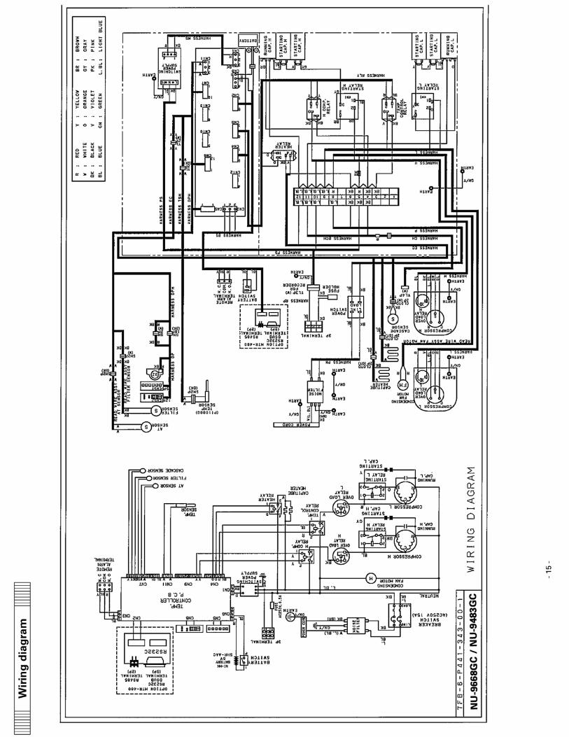
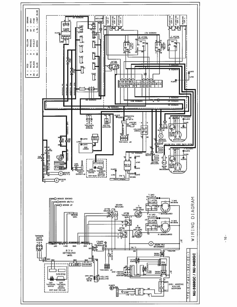
· Wiring diagram ························································································································15
· Circuit diagram ························································································································17
· Control specifi cations ··············································································································18
· Parts layout ······························································································································ 31
· Test data ··································································································································· 33
- Pull-down & Pull-up
- Pull-down pressure
- Current-input
- H/L EVA OUT temperatures
- Temperature uniformity (17points measuring)
- Cycle temperature data
· Instruction manual ·················································································································· 41
Contents

- 1 -
1. New features:
• Energy Saving 10�15%(Target) improving On-Off Control of High stage compressor • Outer Door Handle with rotation stopper for easy use
� • Notice of battery and fan motor life time • New refrigerant that can be bought at local for service - High stage refrigerant: R-404A (HFC refrigerant)
- Low stage refrigerant: R-508B (HFC refrigerant) • HFC-245fa urethane foaming for thermal insulation of frame and door (HCFC free) • COBEX temperature recorder can be installed • Improved Inner Door Handle for reliability up • Additional Vacuum Relief Port and Plastic Cap • Change alarm range from +/- 20oC to +/- 40oC
2. Effective capacity: • NU-9668GC : 668L (23.6 cu.ft.)
Number of 2 inch box: 480 pcs. (Inventory rack IR-220U x 24) • NU-9483GC : 483L (17.1 cu.ft.)
Number of 2 inch box: 320 pcs. (Inventory rack IR-220U x 16)
3. Alarm System: • Temperature alarm: Changeable setting, high/low temperature alarm (+/- 5 to +/- 40oC) • Power failure alarm/Remote alarm terminal/Memory of setting by nonvolatile memory • Filter check alarm • Notice of battery and fan motor life time
4. Optional components: • Automatic temperature recorder: CRE-C-960 • Backup system: NU-UB2
Features

- 2 -
Structural specifications
Model NU-9668GC Exterior dimensions �����
1130�875�1990 (mm) 44.5�34.4�78.3 (inch)
Interior dimensions �����
870�600�1280 (mm) 34.2�23.6�50.4 (inch)
Effective capacity 668 liters (23.6 cu.ft.)
Exterior cabinet Painted steel ( Polyester type: NB Gray )
Interior cabinet Painted steel (Epoxy type: White)
Cabinet insulation Rigid polyurethane foamed in place with Ultra-low Temp prescribed HFC-245fa (HCFC free)
Outer door (1 pc) Painted steel ( Polyester type: Gray Color) Ultra-low Temp prescribed HFC-245fa (HCFC free)
Outer door lock 1 pc
Outer door latch 1 pc, Single action latch type
Inner door (2 pc) Rigid polyurethane foamed in place with Ultra-low Temp prescribed HFC-245fa (HCFC free)
Shelves 3pcs, Stainless steel (SUS-430)
Access port 2 pcs
For CO2 back-up system (back/top �17mm) For temperature recorder sensor (bottom/left �17mm)
Casters 4 pcs (Adjustable leveling feet: 2 pcs)
Refrigerating circuit Cascade system
Evaporator High stage : Cascade type Low stage : Tube on sheet type (sharing with inner cabinet)
Condenser High stage : Fin and tube type Low stage : Cascade type
Compressor High stage :1100W Hermetically sealed type Low stage :1100W Hermetically sealed type
Refrigerant High stage : R-404A Low stage : R-508B
Oil separator SPK-0S02S2
Oil Ze-NIUS22SA
Weight 360 kg 365 kg
Voltage booster None Built-in
Accessories 1 set of key, 1 scraper, 1 stick for air intake port cleaning
Optional components
Temperature recorder : MTR-G85 / MTR-85H Recorder mounting kit : MDF-S3085 for MTR-85H
Back-up system (CVK-UB2): LCO2 Inventory rack: IR-220U
Interface board: MTR-480 LAN interface board: MTR-L03 Data acquisition system: MTR-5000
Back-up system : CVK-UB2 / UB2(I) / UBN2
Specifi cations
- 3 -
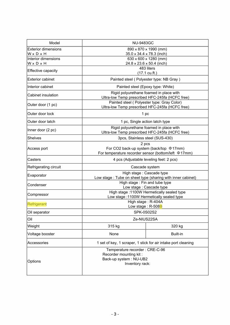
Model NU-9483GC Exterior dimensions �����
890�870�1990 (mm) 35.0�34.4�78.3 (inch)
Interior dimensions �����
630�600�1280 (mm) 24.8�23.6�50.4 (inch)
Effective capacity 483 liters (17.1 cu.ft.)
Exterior cabinet Painted steel ( Polyester type: NB Gray )
Interior cabinet Painted steel (Epoxy type: White)
Cabinet insulation Rigid polyurethane foamed in place with Ultra-low Temp prescribed HFC-245fa (HCFC free)
Outer door (1 pc) Painted steel ( Polyester type: Gray Color) Ultra-low Temp prescribed HFC-245fa (HCFC free)
Outer door lock 1 pc
Outer door latch 1 pc, Single action latch type
Inner door (2 pc) Rigid polyurethane foamed in place with Ultra-low Temp prescribed HFC-245fa (HCFC free)
Shelves 3pcs, Stainless steel (SUS-430)
Access port 2 pcs
For CO2 back-up system (back/top �17mm) For temperature recorder sensor (bottom/left �17mm)
Casters 4 pcs (Adjustable leveling feet: 2 pcs)
Refrigerating circuit Cascade system
Evaporator High stage : Cascade type Low stage : Tube on sheet type (sharing with inner cabinet)
Condenser High stage : Fin and tube type Low stage : Cascade type
Compressor High stage :1100W Hermetically sealed type Low stage :1100W Hermetically sealed type
Refrigerant High stage : R-404A Low stage : R-508B
Oil separator SPK-0S02S2
Oil Ze-NIUS22SA
Weight 315 kg 320 kg
Voltage booster None Built-in
Accessories 1 set of key, 1 scraper, 1 stick for air intake port cleaning
Options
Temperature recorder : CRE-C-96 Recorder mounting kit :
Back-up systNU--UB2:2 Inventory rack:
Back-up system : NU-UB2

- 4 -
Control specifications Model NU-9668GC / NU-9483GC
Temperature control Microprocessor system: Keypad input
Settable range : -50� to -90� (1� graduation) Memory : nonvolatile memory
Running Control High stage compressor: On-Off Control Low stage compressor: On-Off Control
Control Panel
Lamp: ALARM, FILTER, BATTERY BUZZER: Alarm buzzer stop key
ALARM TEST: Alarm test key SET: Set key
: Digit shift key : Numerical value shift key
Temperature sensor Pt. 1000�
Display LED (Green) 1� graduation
Temperature alarm
Buzzer and alarm lamp Chamber temp. 5 40� (changeable)
(factory set; chamber temp.�10� Buzzer operates about 15 minutes later than Alarm lamp
Door alarm N/A Filter alarm Filter check lamp
Power failure alarm Buzzer and alarm lamp and remote alarm switch
Notice of battery life time BATTERY lamp illuminates Integrated time; about 3 years Notice of fan motor life time BATTERY lamp flashes Integrated time; about 6 years
Remote alarm
Contact capacity : DC30V, 2A NC-COM, NO-COM
Temperature alarm or power failure alarm with remote alarm switch
Not in conjunction with buzzer
Key lock Press key for 5 seconds L0 lock release L1 lock
Self diagnostic
When abnormality of thermal sensor, filter sensor, cascade sensor, or ambient temp. sensor
Alternate display of error code and chamber temp. Remote alarm contact ON, Alarm buzzer
Power switch Breaker switch (15A, 250VAC)
Compressor protection
Cascade sensor; L-stage compressor ON at -34oC or less L-stage compressor OFF at -12oC or more
Overload relay and Control of H-stage compressor (substitute of pressure switch)
Delay setting of H/L stage compressor
Changeable delay time of compressor start-up (individual setting is impossible)
Settable range: 3 to 15 minutes (1 minutes gradient)
- 5 -
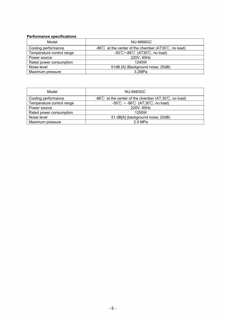
Performance specifications Model NU-9668GC
Cooling performance -86 at the center of the chamber (AT30 , no load) Temperature control range -50 ~-86 (AT30 , no load) Power source 220V, 60Hz Rated power consumption 1240W Noise level 51dB [A] (Background noise; 20dB) Maximum pressure 3.2MPa
Model NU-9483GC
Cooling performance -86 at the center of the chamber (AT;30 , no load) Temperature control range -50 ~ -86 (AT;30 , no load) Power source 220V, 60Hz Rated power consumption 1250W Noise level 51 dB[A] (background noise; 20dB) Maximum pressure 2.5 MPa

- 9 -
NU-9668GC
Item Specifications H side L side
Compressor
220V, 60Hz Type: KS370J1NS-7A Code: 7FB-0-M101-001-06
Type: KS370J1NS-7A Code: 7FB-0-M101-001-06
Power source Single phase, 220V, 60Hz Single phase, 220V, 60Hz
Refrigerant oil Ze-NIUSL22SA Charged q’ty: 850cc
Ze-NIUSL22SA Charged q’ty: 850cc
Cooling system Forced air cooling partially� Oil cooler
Forced air cooling partially� Oil cooler
Condenser Type Fin and tube Cascade condenser
Condenser 12 columns x 4 lines� P6.35mm Fin 88pcs. Coil pipe� �6.35mm
Pre-condenser W 350mm � Frame pipe �6.35mm �
Evaporator Type
Cascade condenser Shell and tube� �80mm
Tube on sheet �9.52mm
Capillary tube Ex. capillary Resistance
PSI�kg/cm2 78 PSI/G 0.37Mpa/G 34 PSI/G
� Length 3000mm 3000mm 500mm Outer diameter �2.4mm �2.0mm �2.4mm Inner diameter �1.2mm (�0.9mm) �1.2mm
Refrigerant R-404A� Charged q’ty: 465g R-508B Charged q’ty: 305g
Oil additive n-Pentane Charged-q’ty: 32cc (20g)
n-Pentane Charged q’ty: 68cc (43g)
Dryer 4A-XH-9 Charged q’ty: 18g 4A-XH-6 Charged q’ty: 58g Condensing fan �230 mm�4 blades
Material: ABS �
Condensing fan motor Type: SE4-E11L5P �
Oil separator � SPK-0S02S2 �
�
�
�
�
�
�
�
�
Cooling unit parts

- 6 -
Dim
ensi
ons
NU
-966
8GC
- 10 -
�
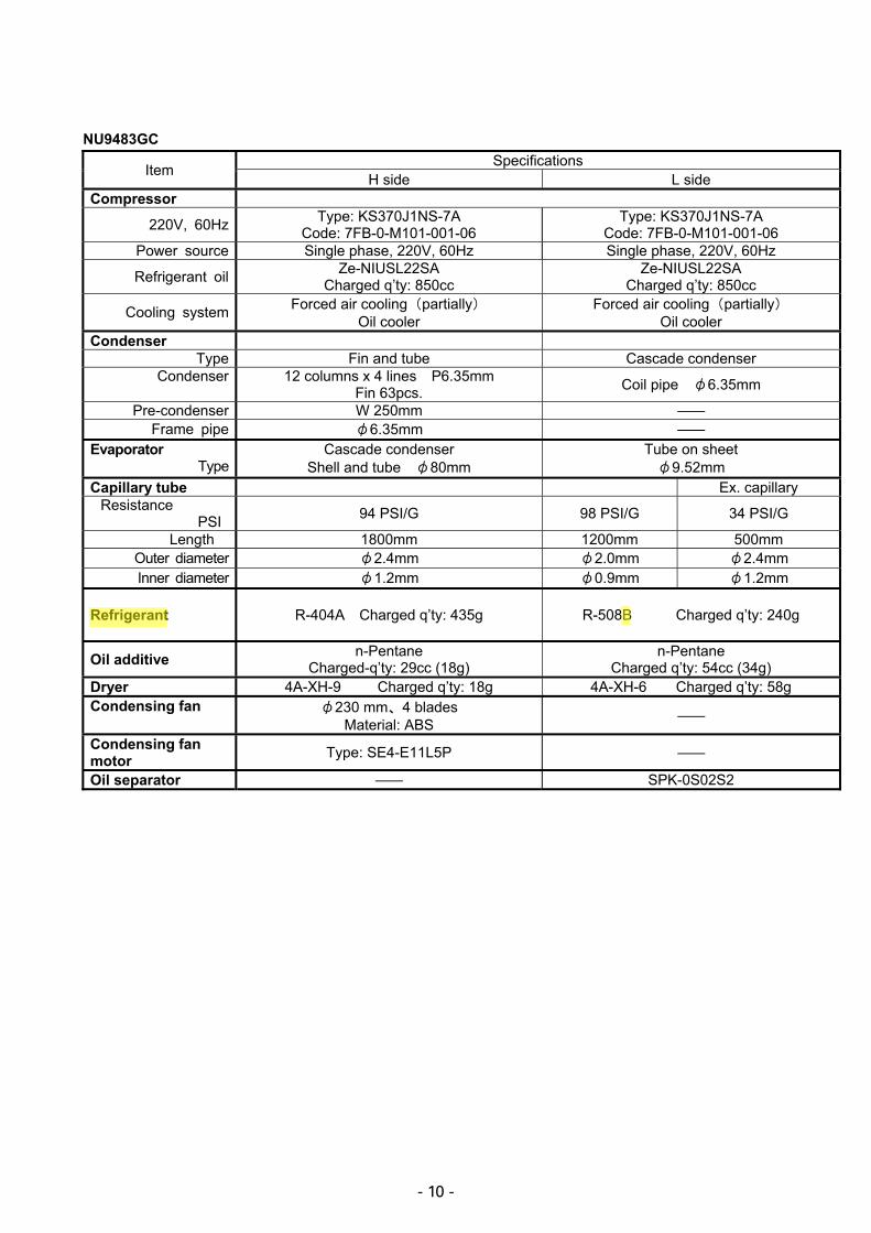
NU9483GC
Item Specifications H side L side
Compressor
220V, 60Hz Type: KS370J1NS-7A Code: 7FB-0-M101-001-06
Type: KS370J1NS-7A Code: 7FB-0-M101-001-06
Power source Single phase, 220V, 60Hz Single phase, 220V, 60Hz
Refrigerant oil Ze-NIUSL22SA Charged q’ty: 850cc
Ze-NIUSL22SA Charged q’ty: 850cc
Cooling system Forced air cooling partially� Oil cooler
Forced air cooling partially� Oil cooler
Condenser Type Fin and tube Cascade condenser
Condenser 12 columns x 4 lines� P6.35mm Fin 63pcs. Coil pipe� �6.35mm
Pre-condenser W 250mm � Frame pipe �6.35mm �
Evaporator Type
Cascade condenser Shell and tube� �80mm
Tube on sheet �9.52mm
Capillary tube Ex. capillary Resistance
PSI 94 PSI/G 98 PSI/G 34 PSI/G
� Length 1800mm 1200mm 500mm Outer diameter �2.4mm �2.0mm �2.4mm Inner diameter �1.2mm �0.9mm �1.2mm
Refrigerant R-404A� Charged q’ty: 435g R-508B Charged q’ty: 240g
Oil additive n-Pentane Charged-q’ty: 29cc (18g)
n-Pentane Charged q’ty: 54cc (34g)
Dryer 4A-XH-9 Charged q’ty: 18g 4A-XH-6 Charged q’ty: 58g Condensing fan �230 mm�4 blades
Material: ABS �
Condensing fan motor Type: SE4-E11L5P �
Oil separator � SPK-0S02S2 �

- 13 -
Compressor (H),(L) Type KS370J1NS-7ACode 7FB-0-M101-001-06
Rated voltage (50/60Hz) 220V 60Hz
AC220V,60HzNU-9668GC / NU-9483GC
Rated voltage (50/60Hz) 220V, 60HzWinding resistance C-S(Aux) 1.64� C-R(Main) 3.35�
Starting relay(H), (L) Type AMVL-300APick up voltage 215~247VAC(60Hz)
Drop out voltage 69~132VAC(60Hz)Overload relay (H), (L) Type MST16AG135/69
Action to the temp. (no current) ON:69±11� OFF:135±5�Action to the current (AT25�) 29.5AAction to the current (AT25�) 29.5A
Operation time 6~16sec.Starting capacitor(H),(L) Rating 250VAC, 160��Running capacitor (H),(L) Rating 400VAC, 25�FCondensing fan motor Type SE4-E11L5P
Rating 220-240VACCap.tube heater Rating 230V, 12W
Resistance(25�� 4700�H Comp. relay Type G4F-11123T
C t t it 20A 250VACContact capacity 20A, 250VACCoil 12VDC
Heater relay Type G2R-1A-TContact capacity 10A, 250VAC
Coil 12VDCTemp. control relay Type G4F-11123T
Contact capacity 20A, 250VACCoil 12VDC
Switching power supply Type ZWS10-12/JSwitching power supply Type ZWS10 12/JRated output DC12V�0.85A
Temperature sensor Type SS-12-TRating 1000�
AT sensor Type 502ATRating 5K�, 25�
Filter sensor Type 502ATRating 5K�, 25�
Cascade sensor Type 502ATR ti 5K� 25�Rating 5K�, 25�
Breaker switch Type BAM215131Rating 250V, 15A
Noise filter Type ZAC2220-11Rating 250VAC, 160MF
Battery switch Type SLE6A2-5Rating 250VAC, 4A
Type 5HR-AACRating 6V, 1100mAH
BatteryRating 6V, 1100mAH
Power transformer Type ATR-D35003(NU-9668GC / NU-9483GC) Primary 208V
Secondary 230VPower transformer Type ATR-HJ61TCfor voltage detection Primary 200V(NU-9668GC / NU-9483GC) Secondary 225V, 240VBoost relay Type G7L-1A-TUB(NU-9668GC / NU-9483GC) Rating 30A, 220V, DC24VP l T DS1E M DC12VPower relay Type DS1E-M-DC12V(NU-9668GC / NU-9483GC) Rating 12V, 0.4A, 125VBreaker switch Type IR11A2E201R(NU-9668GC / NU-9483GC) Rating 250VAC, 20A
Electric parts

- 14 -
The following shows the temperature in thermal sensor (502AT-1) and its resistance value. Temp.
(C) ResistanceValue (k�)
Temp. (C)
ResistanceValue (k�)
Temp. (C)
ResistanceValue (k�)
Temp. (C)
ResistanceValue (k�)
�50 154.5 �36 71.80 �22 35.65 0 13.29
�49 145.9 �35 68.15 �21 33.99 5 10.80
�48 137.8 �34 64.71 �20 32.43 10 8.84
�47 130.2 �33 61.48 �19 30.92 15 7.20
�46 123.1 �32 58.43 �18 29.50 20 6.01
�45 116.5 �31 55.55 �17 28.14 25 5.00
�44 110.2 �30 52.84 �16 26.87 30 4.17
�43 104.4 �29 50.23 �15 25.65 35 3.50
�42 98.87 �28 47.77 �14 24.51 40 2.96
�41 93.70 �27 45.45 �13 23.42 45 2.51
�40 88.85 �26 43.26 �12 22.39 50 2.13
�39 84.18 �25 41.19 �11 21.41 55 1.82
�38 79.80 �24 39.24 �10 20.48 60 1.56
�37 75.67 �23 37.39 �5 16.43 65 1.35
�
�
The following shows the temperature in thermal sensor (PT1000�) and its resistance value. Temp.
(C) ResistanceValue (�)
Temp. (C)
ResistanceValue (�)
Temp. (C)
ResistanceValue (�)
�140 450.83 �70 729.99 0 1000.0
�130 491.47 �60 769.02 10 1038.0
�120 531.83 �50 807.87 20 1076.0
�110 571.92 �40 846.58 30 1113.8
�100 611.76 �30 885.13 40 1151.4
�90 651.38 �20 923.55 50 1189.0
�80 690.78 �10 961.84 60 1226.4
Specifi cations of sensor


- 18 -
1. Key and Switch BUZZER: In alarm condition, audible alarm silences when this key is pressed.
Remote alarm activates and message is not eliminated. When a power failure is occurred (battery back-up), press this key to show a chamber temperature for 5 seconds.
ALARM TEST: When this key is pressed, unit steps into Alarm Test mode with ALARM lamp blinks, intermittent buzzer beeps, digital LED goes off and remote alarm activates. After an elapse time is about 90seconds, unit returns to normal condition. (Auto Return function) If Alarm Test is performed when a battery switch is in off position, “E09” blinks on the display.
SET: Press this key once to activate setting mode with 2nd digit in LED blinks. Press this key again to store a value to be changed.
(Digit shift key)
A blinking digit can change among 1st digit ~ 3rd digit with every time press this key. If this key is pressed for 5 seconds when a chamber temperature is displayed, Key Lock activates with “L_0” is displayed.
(Numerical value shift key)
A blinking digit can increase one by one every time press this key. If this key is pressed for 5 seconds when a chamber temperature is displayed. Function mode activates with “F00” is displayed.
2. Temperature control Setting range: -50�~-90� Display range: -180~50 Setting procedure: Press SET key and set the required value with key and key.
Press SET key to store the value to be changed. Unacceptable setting
range: If a value which is out of setting range is input and SET key is pressed, it is noticed the value cannot be set with audible alarm sounds for 1second.
3. Temperature alarm Setting range: High temperature alarm … Set temp. +5�~+40� (Factory default: 10�)
Low temperature alarm …. Set temp. -5�~-40� (Factory default: -10�) Setting procedure: Keep pressing key over 5 seconds to step to function mode (F00). Input
“F01” for high temperature alarm or “F02” for low temperature alarm. Press SET key to set the value to be changed with the 1st digit blinks. Press SET key again to store the value in the non-volatile memory.
Unacceptable setting range:
If a value which is out of setting range is input and SET key is pressed, it is noticed the value cannot be set with audible alarm sounds for 1second.
4. Key Lock mode and Function mode A) Key Lock mode Setting range: 0 (Unlock), 1 (Lock) Setting procedure: In chamber temperature display, press key for 5 seconds to step to Key
Lock mode. (“L_0” or “L_1” is displayed. Factory default: L_0) Change the value with key and press SET key to store the value in the non-volatile memory.
Control specifi cations

- 19 -
B) Function mode Setting range: 00~50 Display range: 00~59 00, 16 and 33~43, 44~49, 51~59 are unused. Setting procedure: In chamber temperature display, press key for 5 seconds to step� to
function mode (F00 is displayed). Change the blinking 1st digit to desired function code with key and key. Press SET key to be function code available.
Unacceptable setting range
If a value which is out of setting range is input and SET key is pressed, it is noticed the value cannot be set with audible alarm sounds.
5. Error codes E01: Temp. sensor is open circuited E02: Temp. sensor is short circuited E03: Cascade sensor is open circuited E04: Cascade sensor is short circuited E05: Filter sensor is open circuited E06: Filter sensor is short circuited E07: AT sensor is open circuited E08: AT sensor is short circuited E09: Battery switch is in off position or battery is unconnected E10: Compressor temperature is abnormal (1) Temp. sensor Open circuit (E01): When a temperature in temp. sensor is higher than 50�, E01 and “50” are
displayed alternately and audible alarm sounds intermittently and remote alarm contact activates. Compressor is forced to run. Press BUZZER key to silence audible alarm.
Short circuit (E02): When a temperature in temp. sensor is lower than -170�, E02 and “-170”~ “-180” are displayed alternately and audible alarm sounds intermittently and remote alarm contact activates. Compressor is forced to run. Press BUZZER key to silence audible alarm.
(2) Cascade sensor Open circuit (E03): When a temperature in cascade sensor is lower than -65� , E03 and
chamber temperature are displayed alternately, audible alarm sounds intermittently and remote alarm contact activates. Both High and Low side compressors are forced to turn off. Press BUZZER key to silence audible alarm.
Short circuit (E04): When a temperature in cascade sensor is higher than 60� , E04 and chamber temperature are displayed alternately, audible alarm sounds intermittently and remote alarm contact activates. Both High and Low side compressors are forced to turn off. Press BUZZER key to silence audible alarm.
(3) Filter sensor Open circuit (E05): When a temperature in filter sensor is lower than -60�, E05 and chamber
temperature are displayed alternately, audible alarm sounds intermittently and remote alarm contact activates. High side compressor is forced to turn off. Press BUZZER key to silence audible alarm.
Short circuit (E06): When a temperature in filter sensor is higher than 130�, E06 and chamber temperature are displayed alternately, audible alarm sounds intermittently and remote alarm contact activates. Press BUZZER key to silence audible alarm.

- 20 -
(4) AT sensor Open circuit (E07): When a temperature in AT sensor is lower than -60�, E07 and chamber
temperature are displayed alternately, audible alarm sounds intermittently and remote alarm contact activates. Press BUZZER key to silence audible alarm.
Short circuit(E08): When a temperature in AT sensor is higher than 60�, E08 and chamber temperature are displayed alternately, audible alarm sounds intermittently and remote alarm contact activates. Press BUZZER key to silence audible alarm.
(5) Battery SW is in off position or battery is unconnected(E09):
If you press ALARM TEST key when battery switch is in off position or battery is unconnected, E09 is displayed.
(6)Compressor abnormal temperature (E10):
When a temperature in filter sensor is higher than 54�, E10 and chamber temperature are displayed alternately and high side compressor is forced to turn off to notify compressor temperature is abnormal or fan motor is locked. Press BUZZER key to silence audible alarm. When the temperature in filter sensor subtracts ambient temperature is equal or lower than 10�, compressor will turn on.
(7) Error code priority No.1: Cascade sensor error (E03, E04) … Compressor is forced to turn off No.2: Filter sensor error (E05, E06) … Compressor protection is uncontrollable No.3: Abnormal compressor temp.(E10) … Compressor temporary turns off No.4:
No.5: Temp. sensor error (E01, E02) … Compressor is forced to turn on AT sensor error (E07, E08) … Warming-up operation is done with regardless
of any ambient temp.
6. Warning function High temperature
alarm: When chamber temperature is equal or higher than set temperature + high temp. alarm set temperature +1, ALARM lamp and LED blink, audible alarm sounds intermittently after 10 minutes delay, and remote alarm activates. When chamber temperature is equal or lower than set temperature, ALARM lamp and LED go off, audible alarm silences, and remote alarm turns off. When BUZZER key is pressed, audible alarm silences, but remote alarm output does not turn off.
Low temp. alarm: When chamber temperature is equal or lower than set temperature - low temp. alarm set temperature -1, ALARM lamp and LED blink, audible alarm sounds intermittently after 10 minutes delay, and remote alarm activates. When chamber temperature is equal or higher than set temperature, ALARM lamp and LED go off, audible alarm silences, and remote alarm turns off. When BUZZER key is pressed, audible alarm silences, but remote alarm output does not turn off.
Power failure alarm: If a power interrupts for 3 seconds when battery switch is in on-position, ALARM lamp blinks, audible alarm sounds intermittently and remote alarm activates. When a power returns within 3 seconds after the power interrupts, microprocessor resets and unit will start operation in default settings. At the time remote alarm will be active. Press BUZZER key to silence audible alarm, but remote alarm does not turn off. Remote alarm should activate until chamber temperature is stable after the power returns from power failure. When a power interrupts, press BUZZER key to see chamber temperature for 5 seconds.

- 21 -
7. Other function Auto Return: If there are not any key operations for 90 seconds in setting mode, Key Lock
mode and Function mode, unit automatically returns to chamber temperature display.
Ring Back: To prevent someone except for an operator pressing BUZZER key when a unit is in alarming condition, audible alarm sounds again after predetermined setting time elapses even if BUZZER key is pressed to silence audible alarm.
Display of sensor temperatures:
F12: Temperature in temp. sensor (Ex. -80.2�� � Displayed as ‘80.2’) F13: Temperature in cascade sensor (Ex. 67�� � Displayed as ‘067’) F14: Temperature in filter sensor (Ex. 67�� � Displayed as ‘067’) F15: Temperature in AT sensor (Ex. 30�� � Displayed as ‘030’)
Battery accumulation time :
F03: Battery accumulation time is displayed. (Ex. Accumulated 2years and 6months � Displayed as ‘02.5’) When ’02.8’ is shown on the display, BATTERY lamp illuminates to
notify battery replacement. <Reset of battery accumulation time>
Step to F06 and input ‘409’. Press SET key to change accumulation time to ’00.0’. BATTERY lamp goes off.
Condensing fan motor accumulation time :
F32: Condensing fan motor accumulation time is displayed. (Ex. Accumulated 5years and 6months Displayed as ’05.5’) When condensing fan motor accumulation time reaches to 5.6 years,
BATTERY lamp blinks to notify fan motor replacement. <Reset of battery accumulation time> Step to F06 and input ‘410’. Press SET key to change accumulation
time to ’00.0’. BATTERY lamp goes off.
Capillary heater forcibly ON/OFF:
F18: When you input ‘000’ in F18, compressor turns off and capillary heater is forced to turn on.
When you input ‘000’ during capillary heater turns on, it comes to end to turn capillary heater on.
When you input ‘001’, capillary heater never turns on, but compressor turns off in every 18 hours.
ROM version: F30: ROM version is displayed (Ex. Ver. 1.00 � Displayed as “1.00”)
8. Running rate Running rate = (ON time / (ON time + OFF time)) x 100% Condition to start measure running rate:
It regards as ‘cycle start’ when a compressor turns on after it turned off once chamber temperature was lower than set temperature. Running rate should be measured after 2 hours elapse then.
ON time (Min.) = The time until P3.1 in IC5 first reaches from LOW to HIGH OFF time (Min.) = The time until P3.1 in IC5 reaches from HIGH to LOW

- 22 -
Condition to calculate running rate:
ON time OFF time Running rate = 0 = 0 Impossible to calculate
(0%) > 0 = 0 = 0 > 0 > 0 > 0 0 ~ 100%
Note) Running rate cannot be measured when a chamber temperature is higher than set temperature + 4.0�.
Wait until a chamber temperature is stabled.
Diagnosed value of overload running rate: Step to F20 and input ‘000’.
Diagnosed running rate =(-(Set temp.)X0.9)+((ATX0.9-4.5�))-((Set temp.+85�) / 10)) Running status will be obtained by calculating diagnosed running rate. Unit determines by comparing running rate between 8 hours operation after 2 hours elapse after the unit commence cycle operation and diagnosed running rate. (Diagnosed running rate – running rate) < 0 … Normal (DP52 goes off) (Diagnosed running rate – running rate) 0 … Overload operation (DP52 illuminates) 222 = Running rate cannot be obtained by calculation. (DP52 goes off) Diagnosis is done in every 8 hours.
9. Function mode F00 (Unused) F01 Setting of high temperature alarm set temperature F02 Setting of low temperature alarm set temperature F03 Display of battery accumulation time F04 (Unused) F05 Setting of compressor delay time F06 Setting of service code (Code: 384), Reset of accumulation time F07 * Temperature sensor Zero Adjustment F08 * Cascade sensor Zero Adjustment F09 * Compressor continuous running mode … Factory test mode (Unused) F10 * Program running mode … Factory test mode (Unused) F11 * PCB test mode … Factory test mode (Unused) F12 * Display of temperature in temp. sensor F13 * Display of temperature in cascade sensor F14 * Display of temperature in filter sensor F15 * Display of temperature in AT sensor F16 (Unused) F17 * Model code setting (Initialization of non-volatile ROM and memory) F18 * ON/OFF control of capillary heater F19 * Setting of capillary heater ON time
Chamber temp.
�et temp.
Compressor OFF (1st) Reach to set temp.
Compressor ON (1st) Start to cycle run
2 hours 8 hours stabilized (Cycle run)
Start to calculate running rate
Start to diagnose running rate
Diagnosis is done with every 8 hoursuntil chamber temp is higher than Set temp + 4.0

- 23 -
F20 * Setting of diagnosed value of overload running rate F21 Communication ID set F22 Communication mode set F23 * Display of power supply voltage (Unused for MDF-U5486/U5486SC) F24 Linkage between remote alarm and buzzer F25 Setting of Ring Back time F26 * Display of actual operation rate F27 * Display of diagnosed value of overload running rate F28 * Display of delay time of permission for measuring running rate (2 hrs timer) F29 * Display of delay time of permission for measuring running rate (8 hrs timer) F30 * Display of ROM version F31 * Setting of filter alarm F32 Display of condensing fan motor accumulation time F33~F43 Unused F44 * Adjustment of display of power supply voltage F45~F49 Unused F50 Setting of alarm delay time F51~F59 Unused
* Input service code ‘384’ in F06 prior to use function codes which are marked with *. To cancel service code, input “000” in F06 or turn the power off.
Setting procedure:
In chamber temperature display, press key for 5 seconds to display “F00”. Input Function code by pressing key and key. Press SET key to be function mode available.
F01: <Purpose> Setting of high temperature alarm set temperature <Operation> Input F01 and press SET key to display “010” (Factory default).
Setting range is ‘005~040’. Change a value by pressing key and key. Press SET key to store the value and to return to chamber temperature display.
F02: <Purpose> Setting of low temperature alarm set temperature <Operation> Input F02 and press SET key to display “-10” (Factory default).
Setting range is “-05”~“-40”. Change a value by pressing key and key. Press SET key to store the value and to return to chamber temperature display.
F03: <Purpose> Display of battery accumulation time <Operation> Input F03 and press SET key to display alternately F03 with “00.0” (in
case battery used for 36days or less). Press SET key to return to chamber temperature display.
F05: <Purpose> Setting of delay time of compressor when a power is supplied or a power returns from a power failure.
<Operation> Input “F05” and press SET key to display ‘003’ (Factory default). Setting range is ‘003’~’015’. (Unit: Minute) Change a value by pressing key and key. Press SET key to store the value and to return to chamber temperature display.
F06: <Purpose> Input of service code and reset of accumulation time
<Input of service code> Input F06 and press SET key to display ‘000’ (Factory default).
Set service code to “384” by pressing key and key. Press SET key to store the value and to return to chamber temperature display.
- 24 -
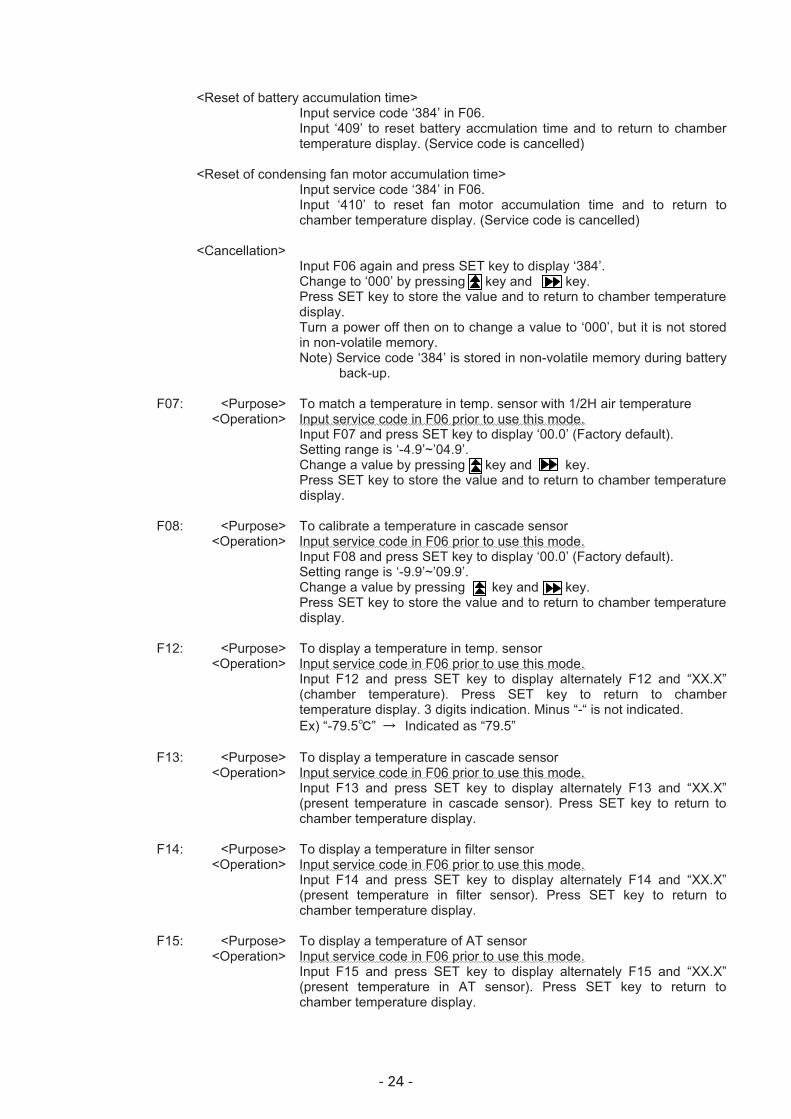
<Reset of battery accumulation time> Input service code ‘384’ in F06.
Input ‘409’ to reset battery accmulation time and to return to chamber temperature display. (Service code is cancelled)
<Reset of condensing fan motor accumulation time> Input service code ‘384’ in F06.
Input ‘410’ to reset fan motor accumulation time and to return to chamber temperature display. (Service code is cancelled)
<Cancellation> Input F06 again and press SET key to display ‘384’.
Change to ‘000’ by pressing key and key. Press SET key to store the value and to return to chamber temperature display. Turn a power off then on to change a value to ‘000’, but it is not stored in non-volatile memory. Note) Service code ‘384’ is stored in non-volatile memory during battery
back-up.
F07: <Purpose> To match a temperature in temp. sensor with 1/2H air temperature <Operation> Input service code in F06 prior to use this mode.
Input F07 and press SET key to display ‘00.0’ (Factory default). Setting range is ‘-4.9’~’04.9’. Change a value by pressing key and key. Press SET key to store the value and to return to chamber temperature display.
F08: <Purpose> To calibrate a temperature in cascade sensor <Operation> Input service code in F06 prior to use this mode.
Input F08 and press SET key to display ‘00.0’ (Factory default). Setting range is ‘-9.9’~’09.9’. Change a value by pressing key and key. Press SET key to store the value and to return to chamber temperature display.
F12: <Purpose> To display a temperature in temp. sensor <Operation> Input service code in F06 prior to use this mode.
Input F12 and press SET key to display alternately F12 and “XX.X” (chamber temperature). Press SET key to return to chamber temperature display. 3 digits indication. Minus “-“ is not indicated. Ex) “-79.5�” � Indicated as “79.5”
F13: <Purpose> To display a temperature in cascade sensor <Operation> Input service code in F06 prior to use this mode.
Input F13 and press SET key to display alternately F13 and “XX.X” (present temperature in cascade sensor). Press SET key to return to chamber temperature display.
F14: <Purpose> To display a temperature in filter sensor <Operation> Input service code in F06 prior to use this mode.
Input F14 and press SET key to display alternately F14 and “XX.X” (present temperature in filter sensor). Press SET key to return to chamber temperature display.
F15: <Purpose> To display a temperature of AT sensor <Operation> Input service code in F06 prior to use this mode.
Input F15 and press SET key to display alternately F15 and “XX.X” (present temperature in AT sensor). Press SET key to return to chamber temperature display.

- 25 -
F17: <Purpose> Change of model code and initialization of non-volatile memory <Change of model code> Service code should be input in F06 prior to use this mode.
Input F17 and press SET key to display ‘00X’. Change a value by pressing key and key. Press SET key to store and return to chamber temperature display. Model code ‘006’: MDF-U5486S/U5486SC ‘007’: MDF-U7486S/U7486SC
<Initial values in non-volatile memory> Zero Adjustment value for temperature sensor:
Zero Adjustment value for cascade sensor: Capillary heater ON time: Auto Return: Chamber set temperature: High temp. alarm: Low temp. alarm: Compressor delay time: Communication ID: Communication mode: Key Lock: Linkage between remote alarm and buzzer: Buzzer tone for filter alarm: Diagnosed value for STATUS 3:
0� 0� 8 minutes 30 minutes -80� +10� -10� 3 minutes 000 000 OFF OFF OFF Fixed
F18: <Purpose> Forcing capillary heater to turn on/off <Operation> Service code should be input in F06 prior to use this mode.
Input F18 and Press SET key to display ‘000’ (Factory default). Change to alternative value ‘000’ or ‘001’ by press key and key. Press SET key to store the value and return to chamber temperature display. 000: Capillary heater is forced to turn on Capillary heater is forced to turn off 001: Capillary heater is inactive
F21: <Purpose> Setting of serial communication ID <Operation> Input F21 and press SET key to display ‘000’ (Factory default).
Setting range is ‘001’ ~ ‘255” by pressing key and key. Press SET key to return to chamber temperature display.
<Serial communication data> Chamber temperature:
Cascade temperature: Power supply voltage: Filter temperature: Ambient temperature: Door status: Capillary heater status: Compressor H status: Compressor L status: Power failure: Running rate: Diagnosed value for overload operation: 2H timer count: 8H timer count: Chamber set temperature: Set temperature of high temp. alarm: Set temperature of low temp. alarm: FILTER lamp status: Remote alarm status: STATUS lamp status: Chamber set temperature for remote mode:
180.0 ~ +50.0 (�) -68.0 ~ +89.0 (�) 0.0 ~ 120.0 (%) -68.0 ~ +160.0 (�) -68.0 ~ +89.0 (�) 0 / 100 (Close/Open) 0 / 100 (OFF/ON) 0 / 100 (OFF/ON) 0 / 100 (OFF/ON) 0 / 100 (OFF/ON) 0~100, 222 (%) 0~100, 999 (%) 0~120 (Minutes) 0~480 (Minutes) -90.0~-50.0 (�) +5.0~+20.0 (�) -5.0~-20.0 (�) 0 / 50 (OFF/ON) 0 / 50 (OFF/ON) 0 / 50 (OFF/ON) -90.0~-50.0 (�)

- 26 -
F22: <Purpose> Setting of serial communication mode <Operation> Input F22 and press SET key to display ‘000’ (Factory default)
Change a value by pressing key and key. Press SET key to store the value and return to chamber temperature display. Control mode (the 3rd digit) 0: Local (initial) 1: Remote Baud rate (the 2nd digit) 0: 2400bps (initial) 1: 4800bps 2: 9600bps Note) Setting value cannot be changed at control panel when control
mode is set to ‘Remote’.
F23: <Purpose> Display of power supply voltage (Unit: %) <Operation> Service code should be input in F06 prior to use this mode.
Input F23 and press SET key to display alternately F23 with ‘xxx’ (present power supply voltage). Press SET key to return to chamber temperature display. Note) This function is ineffective for MDF-U5486S/U5486SC.
F24: <Purpose> Linkage between remote alarm and buzzer <Operation> Input F24 and Press SET key to display ‘000’ (Factory default).
Change a value by pressing key and key. Press SET key to store the value and return to chamber temperature display. 000: Remote alarm does not link with buzzer 001: Remote alarm links with buzzer
F25: <Purpose> Setting of Ring Back time <Operation> Input F25 and press SET key to display “030” (Factory default).
Setting range is ‘000’~’060’. Change a value by pressing key and key. Press SET key to store the value and to return to chamber temperature display.
000: Not Ring Back 010: 10 minutes 020: 20 minutes 030: 30 minutes 040: 40 minutes 050: 50 minutes 060: 60 minutes
F26: <Purpose> Display of running rate (Unit: %) <Operation> Service code should be input in F06 prior to use this mode.
Input F26 and press SET key to display alternately F26 with “XXX” (Present running rate). Press SET key to return to chamber temperature display.
F27: <Purpose> Display of diagnosed value for overload running rate <Operation> Service code should be input in F06 prior to use this mode.
Input F27 and press SET key to display alternately F27 with “XXX” (present diagnosed value of overload running rate). ‘000’ is displayed before it accumulates 480 minutes in 8H timer. Factory default is ‘095’ which is the fixed, except in case diagnosed value is obtained from calculation in F20. Press SET key to return to chamber temperature display.

- 27 -
F28: <Purpose> Display of delay time to start measuring running rate
(2hrs timer; 000~120 min) <Operation> Service code should be input in F06 prior to use this mode.
Input F28 and press SET key to display alternately F28 with ‘xxx’ (present count value for delay time to start measuring running rate). Press SET key to return to chamber temperature display. When a delay time expires (a value reaches to ‘120’), unit will start measuring running rate.
F29: <Purpose> Display of delay time to start diagnosing running rate (8hrs timer; 000~480 min)
<Operation> Service code should be input in F06 prior to use this mode. Input F29 and press SET key to display alternately F29 with ‘xxx’ (present count value for delay time to start diagnosing running rate). Press SET key to return to chamber temperature display. 8hours timer start counting after 2hours timer expires. When a delay time expires (a value reaches to ‘480’), unit will start diagnosing running rate.
F30: <Purpose> ROM version is displayed <Operation> Service code should be input in F06 prior to use this mode.
Input F30 and press SET key to display alternately F30 with “X.XX” (present ROM version). Press SET key to return to chamber temperature display.
F31: <Purpose> Setting of buzzer during filter alarm occurs <Operation> Input F31 and press SET key to display “001” (Factory default).
Change to alternative value ‘000’ or ‘001’ by key and key. Press SET key to revert to chamber temperature display. 000: Buzzer OFF 001: Buzzer ON
F32: <Purpose> Display of accumulation time of condensing fan motor <Operation> Input F32 and press SET key to display alternately F32 with ‘xx.x’
(accumulation time). Press SET key to return to chamber temperature display.
F44: <Purpose> Adjustment for difference of power supply voltage <Operation> Input F44 and press SET key to display ‘000’ (Factory default).
Setting range is ‘000’~’003’. Press SET key to return to chamber temperature display.
Input value Adjustment of display 000 0% (Power supply voltage is not increased) 001 3% increased 002 5% increased 003 7% increased
F50: <Purpose> Setting of alarm delay time <Operation> Input F50 and press SET key to display ‘015’ (Factory default).
Setting range is ‘000’~’015’. Change a value by pressing key and key. Press SET key to store the value and to return to chamber temperature display.
- 28 -
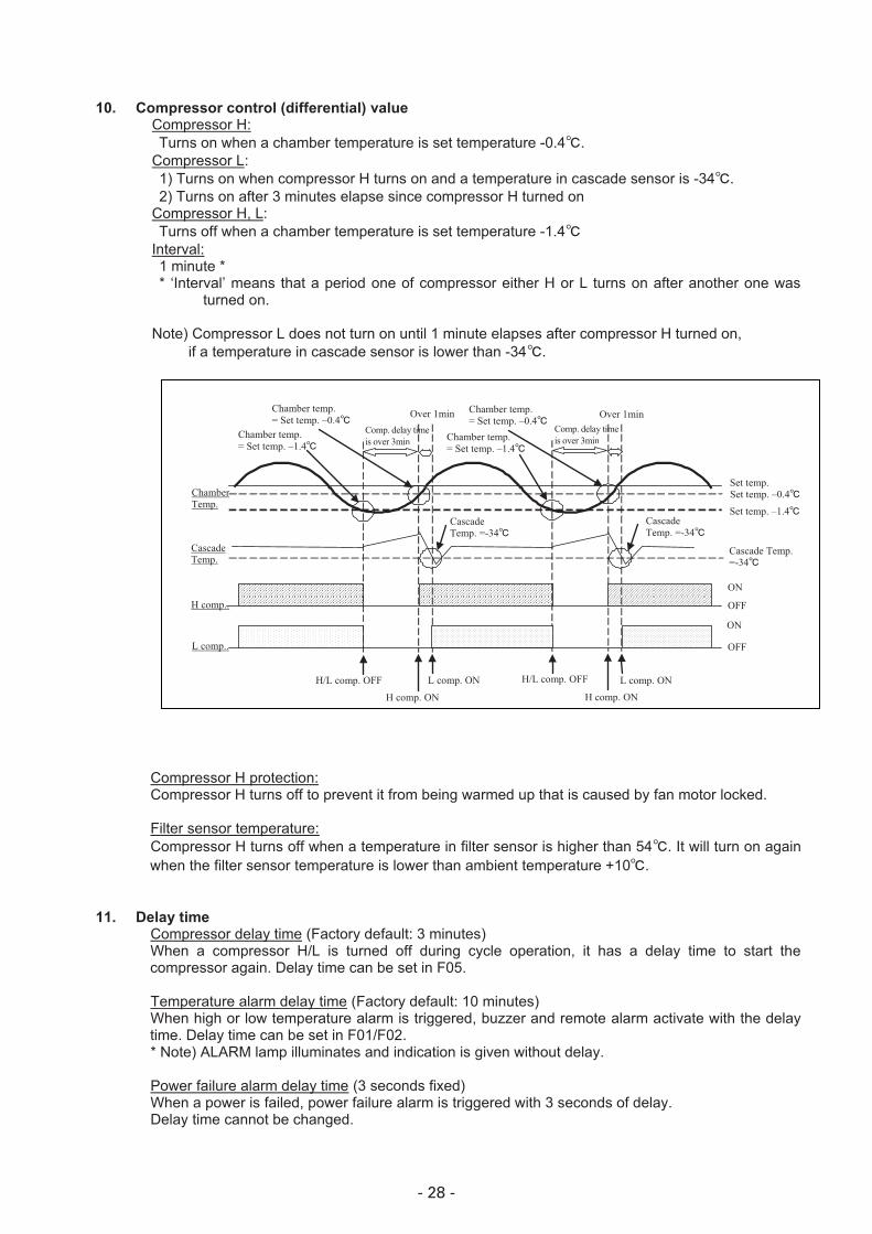
10. Compressor control (differential) value Compressor H:
Turns on when a chamber temperature is set temperature -0.4�. Compressor L: 1) Turns on when compressor H turns on and a temperature in cascade sensor is -34�. 2) Turns on after 3 minutes elapse since compressor H turned on
Compressor H, L: Turns off when a chamber temperature is set temperature -1.4�
Interval: 1 minute * * ‘Interval’ means that a period one of compressor either H or L turns on after another one was
turned on. Note) Compressor L does not turn on until 1 minute elapses after compressor H turned on,
if a temperature in cascade sensor is lower than -34�.
Compressor H protection: Compressor H turns off to prevent it from being warmed up that is caused by fan motor locked.
Filter sensor temperature: Compressor H turns off when a temperature in filter sensor is higher than 54�. It will turn on again
when the filter sensor temperature is lower than ambient temperature +10�.
11. Delay time Compressor delay time (Factory default: 3 minutes) When a compressor H/L is turned off during cycle operation, it has a delay time to start the
compressor again. Delay time can be set in F05.
Temperature alarm delay time (Factory default: 10 minutes) When high or low temperature alarm is triggered, buzzer and remote alarm activate with the delay
time. Delay time can be set in F01/F02. * Note) ALARM lamp illuminates and indication is given without delay.
Power failure alarm delay time (3 seconds fixed) When a power is failed, power failure alarm is triggered with 3 seconds of delay.
Delay time cannot be changed.
Chamber Temp.
H comp..
Cascade Temp.
L comp..
H/L comp. OFF H/L comp. OFF
H comp. ON
L comp. ON
ON
L comp. ON
ON
OFF
OFF
Cascade Temp. =-34�
Cascade Temp. =-34�
Cascade Temp.=-34�
Set temp. –1.4�
Set temp. –0.4�Set temp.
Chamber temp. = Set temp. –0.4�
Chamber temp. = Set temp. –1.4�
Comp. delay time is over 3min
Over 1min Chamber temp. = Set temp. –0.4�
Chamber temp. = Set temp. –1.4�
H comp. ON
Over 1min Comp. delay time is over 3min

- 29 -
12. Prevention for oil logging in capillary Purpose: Capillary heater which attached with capillary is powered by turning both High and Low side
compressor off regularly to prevent oil logging in capillary. Operation: Both High and Low side compressor are turned off, while a capillary heater relay (CN4: 3-4) is
turned on. DP3 (red lamp) is lit. Frequency: 8 minutes in every 18 hours (Setting time are changeable in F19) Timing to start operation: (1) 9 seconds after both High and Low side compressor are turned off during cycle operation.
(2) Both High and Low side compressors are forced to turn off when they kept running for 60 minutes or more after they were forced to turn on.
Control of capillary heater: Capillary heater is forced to turn on or off in F18.
14. Sensor offset Offset value:
(1) Temperature sensor: +1.3� (Changeable in F07) (2) Cascade sensor: +/-0.0� (Changeable in F08) (3) Filter sensor: +/-0.0� (4) AT sensor: +/-0.0�
15. Remote alarm terminal Operation:
When an alarm is occurred, remote alarm contact (RLY2) switches the position.
CN3 1 – 2 (N.O.) 1 – 3 (N.C.)
Normal Open Close In alarm Close Open
16. Operation and setting after a power is reset
Settings when a power is supplied (Power on reset)
Alarms: OFF Compressors: OFF Remote alarm: OFF Ring Back: 30 minutes Timers: Reset 2H timer, 8H timer: 0 (Reset) Counting of compressor L OFF period: Reset Setting data: Read by non-volatile memory
Momentary power failure: When a chamber temperature is lower than set temperature+10�, unit will determine as
‘Momentary power failure’ is occurred.
Settings after unit returns from power failure:
Alarms: OFF Compressors: OFF Remote alarm: ON Timers: Reset 2H timer, 8H timer: 0 (Reset) Counting of compressor L OFF period: Reset Setting data: Read by non-volatile memory
- 30 -
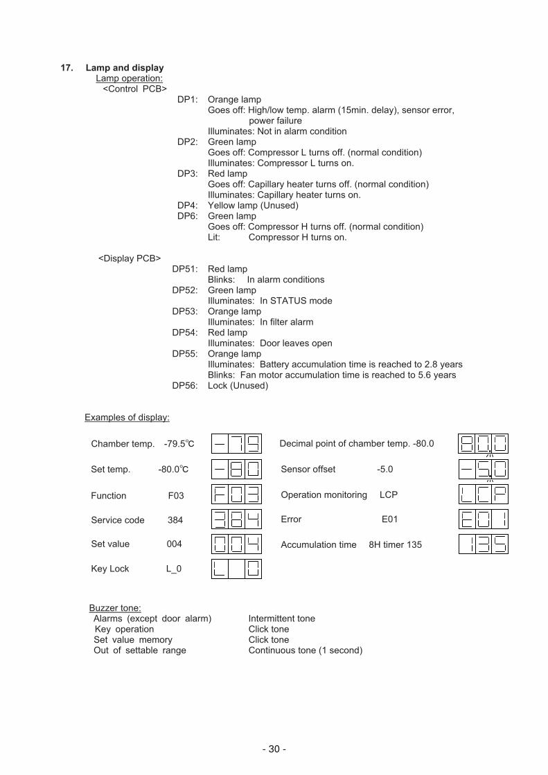
17. Lamp and display Lamp operation: <Control PCB> DP1: Orange lamp
Goes off: High/low temp. alarm (15min. delay), sensor error, power failure
Illuminates: Not in alarm condition DP2: Green lamp
Goes off: Compressor L turns off. (normal condition) Illuminates: Compressor L turns on.
DP3: Red lamp Goes off: Capillary heater turns off. (normal condition) Illuminates: Capillary heater turns on.
DP4: Yellow lamp (Unused) DP6: Green lamp
Goes off: Compressor H turns off. (normal condition) Lit: Compressor H turns on.
<Display PCB> DP51: Red lamp
Blinks: In alarm conditions DP52: Green lamp
Illuminates: In STATUS mode DP53: Orange lamp
Illuminates: In filter alarm DP54: Red lamp
Illuminates: Door leaves open DP55: Orange lamp
Illuminates: Battery accumulation time is reached to 2.8 years Blinks: Fan motor accumulation time is reached to 5.6 years
DP56: Lock (Unused)
Examples of display:
Buzzer tone: Alarms (except door alarm) Intermittent tone Key operation Click tone Set value memory Click tone Out of settable range Continuous tone (1 second)
Chamber temp. -79.5� Decimal point of chamber temp. -80.0
Set temp. -80.0� Sensor offset� � � -5.0
Function� � � F03 Operation monitoring� � LCP
Service code� � � 384 Error � � � � E01
Set value� � � 004 Accumulation time� � 8H timer 135
Key Lock� � � L_0
- 31 -
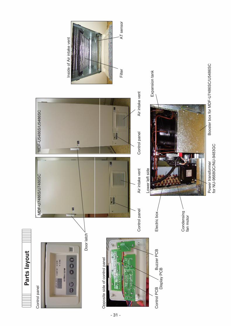
Con
trol p
anel
Insi
de o
f Air
inta
ke v
ent
Doo
r lat
ch
Opp
osite
sid
e of
con
trol p
anel
Filte
rA
T se
nsor
Con
trol p
anel
Air
inta
ke v
ent
Con
trol p
anel
Air
inta
ke v
ent
Low
er le
ft si
deE
xpan
sion
tank
Con
trol P
CB
Buz
zer P
CB
Ele
ctric
box
Dis
play
PC
B
Con
dens
ing
fan
mot
or
Pow
er tr
ansf
orm
erB
oost
er b
ox fo
r MD
F-U
7486
SC
/U54
86S
Cfo
r NU
-966
8GC
/NU
-948
3GC
MD
F-U
7486
S/U
7486
SC
MD
F-U
5486
S/U
5486
SC
Part
s la
you
t
- 32 -
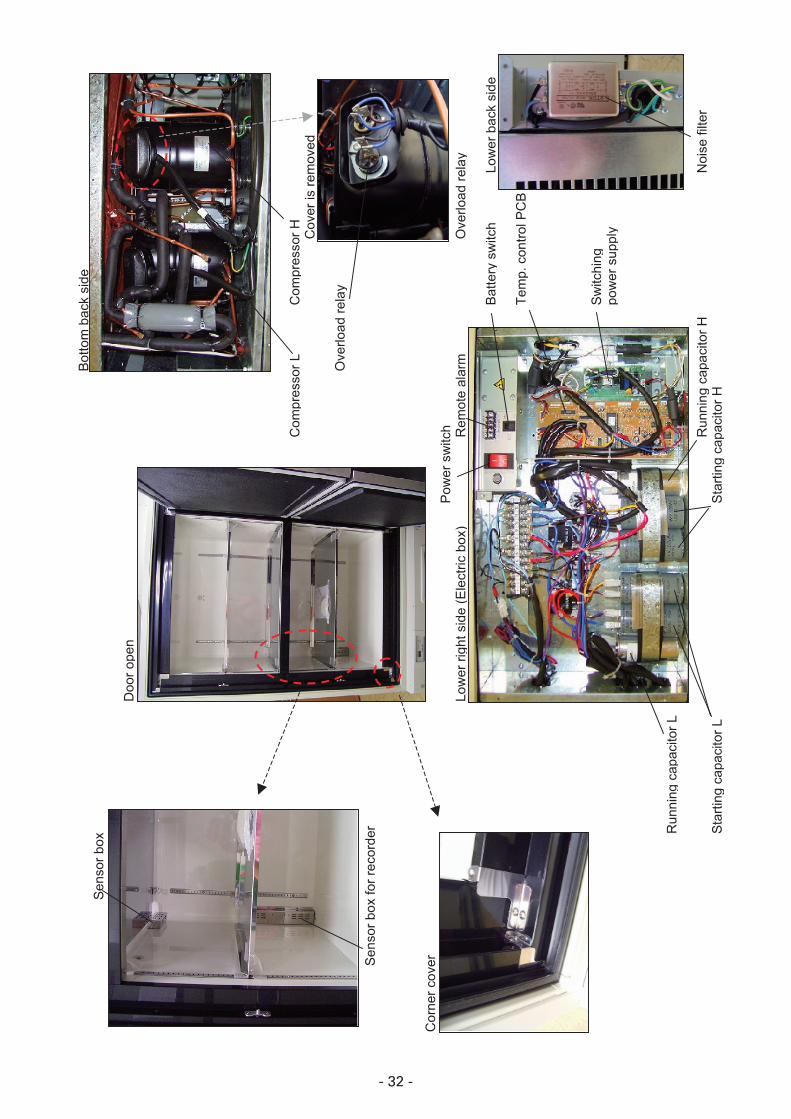
Bot
tom
bac
k si
deS
enso
r box
Doo
r ope
n
Com
pres
sor L
Com
pres
sor H C
over
is re
mov
ed
Ove
rload
rela
y
Sen
sor b
ox fo
r rec
orde
r
Cor
ner c
over
Pow
er s
witc
hLo
wer
righ
t sid
e (E
lect
ric b
ox)
Rem
ote
alar
mO
verlo
ad re
lay
Bat
tery
sw
itch
Low
er b
ack
side
Tem
p. c
ontro
l PC
B
Sw
itchi
ng
pow
er s
uppl
y
Run
ning
cap
acito
r L
Run
ning
cap
acito
r HN
oise
filte
rS
tarti
ng c
apac
itor L
Sta
rting
cap
acito
r H

- 33 -
*Following data are the reference only.
NU-9668GC Pull-down data AT:30�
-100
-80
-60
-40
-20
0
20
40
0 1 2 3 4 5 6 7 8 9 10 11 12 13 14 15
Time[hour]
Tem
pera
ture
[ �]
NU-9668GC Pull-up data AT:30�
-90
-80
-70
-60
-50
-40
-30
-20
-10
0
0 1 2 3 4 5 6 7 8 9
Time[hour]
Tem
pera
ture
[ �]
Test data

- 34 -
NU-9483GC Pull-up data AT:30�
-90
-80
-70
-60
-50
-40
-30
-20
-10
0
0 1 2 3 4 5 6 7 8 9
Time[hour]
Tem
pera
ture
[ �]
NU-9483GC Pull-down data AT:30�
-100
-80
-60
-40
-20
0
20
40
0 1 2 3 4 5 6 7 8 9 10 11 12 13 14 15
Time[hour]
Tem
pera
ture
[ �]

- 35 -
NU-9668GC Pull-down pressure��220V60Hz�AT35�
0
0.5
1
1.5
2
2.5
3
3.5
0 1 2 3 4 5 6 7 8 9 10 11 12 13 14 15Time�Hour
Pre
ssur
e �M
Pa
H�PsH�PdL�PsL�Pd
NU-9668GC Pull-down pressure 220V60Hz, AT35�
0.0
0.5
1.0
1.5
2.0
2.5
3.0
3.5
0 1 2 3 4 5 6 7 8 9 10 11 12 13 14 15
Time(hour)
Pre
ssur
e(M
Pa)
H psH pdL psL pd

- 36 -
NU-9668GC Current-input�220V60Hz�AT35�
0
1
2
3
4
5
6
7
8
0 3 6 9 12 15Time�Hr
Cur
rent�A
00.20.40.60.811.21.41.61.822.22.42.62.83
Pow
er c
onsu
mpt
ion ��
W
NU-9668GC Current-Input 220V60Hz, AT35�
0
1
2
3
4
5
6
7
8
0 3 6 9 12 15
Time(hour)
Cur
rent
(A)
0.00.20.40.60.81.01.21.41.61.82.02.22.42.62.83.0
Current (A)
Power consumption (kW)
Current (A)
Power consumption (kW)
Pow
er c
onsu
mpt
ion
(kW
)

- 37 -
NU-9668GC H/L�EVA OUT temperature�AT30�
-100
-80
-60
-40
-20
0
20
40
0 2 4 6 8 10 12 14Time�Hour
Tem
pera
ture��
HEVAoutLEVAout1/2hair
NU-9668GC H/L EVA OUT Temperature AT30�
-100
-80
-60
-40
-20
0
20
40
0 2 4 6 8 10 12 14
Time(hour)
Tem
pera
ture
( �)
HEVAOUT�EVAOUT1/2h air

- 38 -
Temperature uniformity - 17 points measuring
For NU-9668GCConditions:Ambient temperature: 30�Power supply: 220V,60Hz,�1No load
Measuring points
��������:W: 5% inside of tray widthD: 5% inside of tray depthH: 5% inside of inner height
����:W: 5% inside of tray widthD: 5% inside of tray depthH: 10mm upper from top of tray
���:W: Center of shelfD: Center of shelfH: 10mm upper from top of tray
� :W: Center of shelfD: Center of shelfH: 5% inside of inner height
870mm
1280mm
600mm
�
��
�
�
��
� �
�
��
�
�
�
�
- 39 -
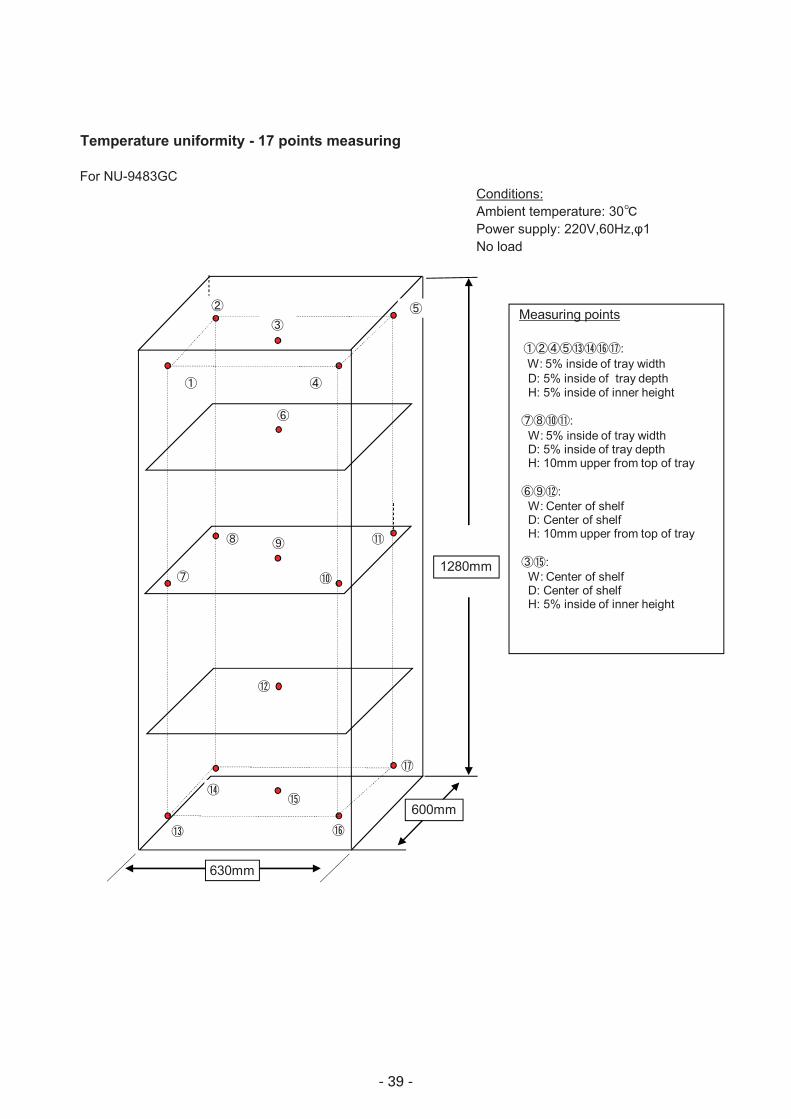
Temperature uniformity - 17 points measuring
For NU-9483GCConditions:Ambient temperature: 30�Power supply: 220V,60Hz,�1No load
Measuring points
��������:W: 5% inside of tray widthD: 5% inside of tray depthH: 5% inside of inner height
����:W: 5% inside of tray widthD: 5% inside of tray depthH: 10mm upper from top of tray
���:W: Center of shelfD: Center of shelfH: 10mm upper from top of tray
� :W: Center of shelfD: Center of shelfH: 5% inside of inner height
630mm
1280mm
600mm
�
��
�
�
��
� �
�
��
�
�
�
�
- 40 -
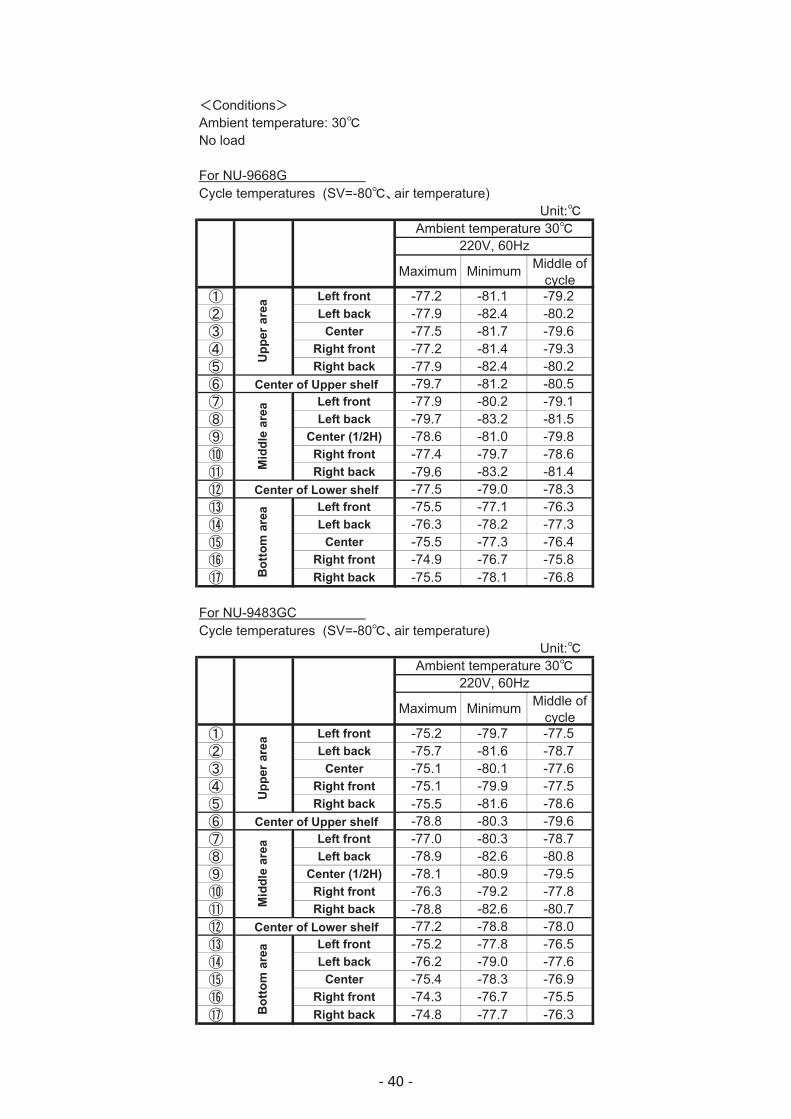
!Conditions"Ambient temperature: 30�No load
For NU-9668GCycle temperatures (SV=-80��air temperature)
Unit:�
Maximum Minimum Middle ofcycle
� Left front -77.2 -81.1 -79.2� Left back -77.9 -82.4 -80.2� Center -77.5 -81.7 -79.6� Right front -77.2 -81.4 -79.3� Right back -77.9 -82.4 -80.2� -79.7 -81.2 -80.5� Left front -77.9 -80.2 -79.1� Left back -79.7 -83.2 -81.5� Center (1/2H) -78.6 -81.0 -79.8� Right front -77.4 -79.7 -78.6� Right back -79.6 -83.2 -81.4� -77.5 -79.0 -78.3� Left front -75.5 -77.1 -76.3� Left back -76.3 -78.2 -77.3 Center -75.5 -77.3 -76.4� Right front -74.9 -76.7 -75.8� Right back -75.5 -78.1 -76.8
For NU-9483GCCycle temperatures (SV=-80��air temperature)
Unit:�
Maximum Minimum Middle ofcycle
� Left front -75.2 -79.7 -77.5� Left back -75.7 -81.6 -78.7� Center -75.1 -80.1 -77.6� Right front -75.1 -79.9 -77.5� Right back -75.5 -81.6 -78.6� -78.8 -80.3 -79.6� Left front -77.0 -80.3 -78.7� Left back -78.9 -82.6 -80.8� Center (1/2H) -78.1 -80.9 -79.5� Right front -76.3 -79.2 -77.8� Right back -78.8 -82.6 -80.7� -77.2 -78.8 -78.0� Left front -75.2 -77.8 -76.5� Left back -76.2 -79.0 -77.6 Center -75.4 -78.3 -76.9� Right front -74.3 -76.7 -75.5� Right back -74.8 -77.7 -76.3
Center of Lower shelf
Bot
tom
are
a
Ambient temperature 30�220V, 60Hz
Upp
er a
rea
Ambient temperature 30�220V, 60Hz
Upp
er a
rea
Mid
dle
area
Bot
tom
are
a
Center of Lower shelf
Center of Upper shelf
Center of Upper shelf
Mid
dle
area

rinted in Japan
SM9910243 Printed in Japan
2100 Fernbrook Lane Plymouth, MN 55447 U.S.A. 1.800.328.352 www.nuaire.com Printed in J Printed in Japan


