1.1 General Description The VeriDose V is a microprocessor based five-channel diode dosimeter for use with radiation sensing diodes. The unit is manufactured by Fluke Biomedical. It provides integrated dose and dose rate display capabilities for patient dose verification and quality assurance in radiation therapy. The diodes may be attached to a patient's skin during radiation therapy when the patient is being exposed to x-rays or electrons. The diodes produce a current directly proportional to the ionizing radiation to which they are exposed. These diodes are directly connected to the VeriDose V. Dose measurements are displayed in units of cGy while rate measurements are shown in units of cGy/minute.
The VeriDose V is intended as a readout for detector diodes (user supplied) used for the detection of ionizing radiation, it should only be used by responsible persons who have the proper training in the interpretation of its readings and the appropriate safety procedures to be followed in the presence of radiation.
The VeriDose V is compatible with VeriDose diodes as well as most industry standard radiation sensitive diodes. VeriDose diodes are available to cover a wide range of energies. These diodes feature a hemi-spherical shape for improved surface contact with the patient. The model numbers for the VeriDose diodes are shown in the accessories table.
The VeriDose V may be used with continuous and pulsed radiation beams (Cobalt 60 and linear accelera-tors). The VeriDose V is well suited for use with both static and dynamic wedge fields as well as irregular fields and MLC applications.
The VeriDose V features a backlit LCD (Liquid Crystal Display) and a menu driven user interface. A keypad with 5 soft-keys, a scroll up, scroll down and enter key provide for easy navigation through the menu structure. An ON/OFF switch, power input connector and RS-232 serial port are located on the right side panel. The rear panel contains the five BNC connectors for the diode inputs and a parallel printer port. Calibration data can be stored for 25 groups, containing up to five diodes each. These user-calibrated groups can be recalled and selected for subsequent measurements. User calibration and treatment data can be transmitted to a printer or computer. An optional label printer is available for direct printout of measured dose to affix to patient charts. A real-time clock provides a time and date stamp for all measurements. The RAM (Random Access Memory) is backed-up by an internal 3.6 V, 370 mAh lithium battery (P/N16-41).
1.2 Features • Backlit Liquid Crystal Display (LCD) and easy-to-use soft-key menu system
• Five independent detector channels with BNC connectors
• Automatic zeroing of each channel to minimize the effects of drift
• RS-232 serial port for computer interface
• Parallel printer interface
• User entered institution name printed on reports
• A group database containing up to 25 diode groups, with up to 5 diodes per group, may be configured, labeled and calibrated by the operator for subsequent measurements.
• Provides an alarm setting for each individual channel
Nuclear Associates 37-705 Operators Manual
1-2
• Can be used as a stand-alone system without the need for a PC
1.3 Specifications
Input Circuitry Five bi-polar electrometer channels w/digital zeroing and gain control
Display 240 x 64 dot Liquid Crystal Display (LCD) 8 line x 40 characters, with CCF backlight
Clock Real Time Clock, battery operated, US or Euro format
Alarm User selectable alarm level for each channel
User Controls On-off switch 5 column select soft-keys for control functions Scroll up, scroll down and enter key for data entry
User Setup Parameters Stored in non-volatile, battery-backup RAM
Computer Interface RS-232, 19.2 BAUD, 8, N, 1 Data format: standard-decimal points, or Euro-style commas
Printer Interface Parallel, selectable drivers for LaserJet III and later, with ASCII (text) output compatible with most other printers, RS-232 Serial Port used for Label printer
Operating Temperature 50° to 86°F (10° to 30°C) Relative humidity: 5 to 95% non-condensing
Weight 2.5 lbs. (1.2 kg)
Size 9 (w) x 8.5 (d) x 2.5 in (h) (22.9 x 21.6 x 6.4 cm) EMI shielded
Power 120 VAC, 60 Hz or 230 VAC, 50 Hz to 12 VDC @ 1A AC adapter, UL, CSA, CE
** The rate range is dependent upon diode sensitivity and beam characteristics. The maximum input charge cannot exceed 7nC per 100mS for negative polarity diodes, or 2.5nC per 100mS for positive polarity diodes.
IntroductionAccessories 1
1-3
1.4 Accessories
Supplied with VeriDose V Description Part Number One of the following, Power converter 12 VDC @ 1A
Input – 120 VAC, 60 Hz, 22 W (US, Canada) 14-328 Input – 230 VAC, 50 Hz, 22 W (Europe) 14-401 Input – 240 V AC, 50 Hz, 21.2 W (UK) 14-414 Input – 240 VAC, 50 Hz, 21.2 W (Australia) 14-414 and 14-416
Description Part Number Label printer 37-705-1101 Additional labels 81-705-1100 Adaptor, 9-pin D-Sub to RJ11, Male 88-705-1105 (173073) Cable, RS-232 88-446- 7000
Diode extension cable, 10 m 88-490
Diode and extension cable, 3 m 88-490-1000 VeriDose Diodes
Description Part Number 1 MV to 4 MV photon diode, Blue 30-471-8000
5 MV to 11 MV photon diode, Yellow 30-472-8000
12 MV to 17 MV photon diode, Red 30-473-8000
18 MV to 25 MV photon diode, Green 30-474-8000
6 MeV to 25 MeV electron diode, Gray 30-475-8000 Dual purpose phantom, Flat/sym. and energy check 37-705-5000
Calibration fixture 37-705-4000
Diode extension cable, 10 m 88-490
Diode Holder, 5 slot 30-492-1000
Calibration Jig, 5 slot 30-492-5200
VeriDose QC Phantom 37-705-7000
Acrylic slab 9.85 in SQ x 2 cm 37-705-7061
Acrylic slab 9.85 in SQ x 1 cm 37-705-7062
Acrylic slab 9.85 in SQ x .5 cm 37-705-7063
VeriDose acrylic slab set 37-705-7069
Cable assembly, 50 ft 37-705-7300
Cable assembly, 80 ft 37-705-7301
Nuclear Associates 37-705 Operators Manual
1-4
1.5 Receiving Inspection
Upon receipt of the unit:
1. Check the packaging and its contents for damage. If damage is evident, file a claim with the carrier and contact Fluke Biomedical at 440.248.9300 for further instructions.
2. Remove the packaging and visually inspect the unit for damage.
3. Check that all items on the packing list have been received and are in good condition.
If items are missing or damaged, contact Fluke Biomedical at 440.248.9300 for further instructions.
1.6 Storage
If the unit is to be stored prior to use, pack it in the original container, if possible, and store in an environ-ment free of corrosive materials, fluctuations in temperature and humidity, and vibration and shock.
Prior to use, check the condition and functionality of the device. Also check that the calibration is still valid. Periodic re-calibration is usually required by individual radiation safety and/or quality assurance programs. Please consult your local radiation safety or quality assurance office if you have any questions.
1.7 Routine Cleaning
Do not immerse the Model 37-705 VeriDose V. The unit is not waterproof. Liquid could damage the internal circuitry. The unit should be kept clean and free from dirt and contamination. The unit may be cleaned by wiping with a damp cloth using any commercially available cleaning or decontamination agent.
NOTE
CAUTION
IntroductionProcedures, Warnings, and Cautions 1
1-5
1.8 Procedures, Warnings, and Cautions
The equipment described in this manual is intended to be used for the detection and measurement of ionizing radiation. It should be used only by persons who have been trained in the proper interpretation of its readings and the appropriate safety procedures to be followed in the presence of radiation.
Although the equipment described in this manual is designed and manufactured in compliance with all applicable safety standards, certain hazards are inherent in the use of electronic and radiometric equipment.
WARNINGS and CAUTIONS are presented throughout this document, when applicable, to alert the user to potentially hazardous situations. A WARNING is a precautionary message preceding an operation that has the potential to cause personal injury or death. A CAUTION is a precautionary message preceding an operation that has the potential to cause permanent damage to the equipment and/or loss of data. Failure to comply with WARNINGS and CAUTIONS is at the user’s own risk and is sufficient cause to terminate the warranty agreement between Fluke Biomedical, Radiation Measurement Services and the customer.
Adequate warnings are included in this manual and on the product itself to cover hazards that may be encountered in normal use and servicing of this equipment. No other procedures are warranted by Fluke Biomedical. It shall be the owner’s or user’s responsibility to see to it that the procedures described here are meticulously followed, and especially that WARNINGS and CAUTIONS are heeded. Failure on the part of the owner or user in any way to follow the prescribed procedures shall absolve Fluke Biomedical and its agents from any resulting liability.
Indicated battery and other operational tests must be performed prior to each use to assure that the instrument is functioning properly. If applicable, failure to conduct periodic performance tests in accordance with ANSI N323-1978 (R1983) Radiation Protection Instrumentation Test and Calibration, paragraphs 4.6 and 5.4, and to keep records thereof in accordance with paragraph 4.5 of the same standard, could result in erroneous readings or potential danger. ANSI N323-1978 becomes, by this reference, a part of this operating procedure.
1.9 Warning and Caution Summary
Warning Summary The VeriDose V is intended to be used as a quality assurance device only. This product is not a primary delivered dose measurement device and as such poses no known possible patient risk. Since this product is an independent quality assurance device used for monitoring delivered dose, it plays no role whatsoever in the administration of radiation to the patient and in no way affects the performance of the radiation therapy system.
VeriDose V is intended as a readout for detector diodes (user supplied) used for the detection of ionizing radiation, it should only be used by responsible persons who have the proper training in the interpretation of its readings and the appropriate safety procedures to be followed in the presence of radiation.
Caution Summary The VeriDose V is not to be used as a primary calibration device nor is it to be used as a part of a primary calibration system. The operator must exercise caution and care when connecting detectors to the VeriDose V and selecting user calibrated detector groups as these actions directly affect the accuracy of the device. For this reason it is the operators' responsibility to clearly mark the diode and its' connector to prevent connection to the wrong input channel and to select the appropriate user calibration group prior to use.
Nuclear Associates 37-705 Operators Manual
(Blank page)
OperationMenu Structure Overview 2
2-1
Section 2 Operation
2.1 Menu Structure Overview
2.1.1 General description
The VeriDose V provides a comprehensive menu structure allowing immediate access to frequently used functions. The five keys, located below the display, relate to the displayed functions in each of the respec-tive columns for selection and control. These keys are referred to as "soft-keys" since their operation at any given time depends on the menu being displayed. The three keys to the right of the display, up and down arrows and enter key, control scrolling and entry operations. A group database containing up to 25 diode groups, with up to 5 diodes (channels) per group may be configured, labeled and calibrated by the operator for subsequent measurements. The following section describes in detail the operation of the menu functions. Menu items shown in italics throughout the manual indicate user-entered names.
2.1.2 Menu operation
The "main" menu screen is shown below (Measure Dose screen #1). The VeriDose V's mode of operation is controlled from this mode select screen. There are 5 column control keys located directly below the display. The first key on the left is the "mode" key. Pressing the mode key at any time returns to the mode select screen and selects the mode column. The selected column is indicated by the presence of the menu cursor (blinking reverse video) within the column. Pressing the mode key again will move the blink-ing menu cursor up through the column of available modes: MEASURE, SELECT, SETUP and CAL (calibrate). Pressing the up or down arrow keys moves the menu cursor up or down through the available modes. As the cursor moves, all of the options available for that mode are displayed in the columns to the right.
Pressing a soft-key to the right of the mode key moves the blinking menu cursor into the selected column. Pressing the soft-key again will move the blinking menu cursor up through the column of available op-tions. Pressing the up or down arrow keys moves the menu cursor up or down through the selected column of available options. After options have been highlighted, the enter key may be pressed to start the selected mode with the selected options. Pressing the mode key at any time returns to the mode select screen.
Under various conditions message boxes will appear in the lower right corner of the display. These messages provide special instructions and/or status information.
Dose Screen #1
MEASURE DOSE group name SELECT RATE 1 ON SETUP ALARMS 2 ON CAL REPORT 3 OFF 4 OFF 5 OFF MODE OPTION CHANNEL STATUS
Nuclear Associates 37-705 Operators Manual
2-2
2.1.3 Start-up Screen
When the VeriDose V is powered up the startup screen is displayed while the unit performs a self-test. This test includes a non-destructive, read/write Ram memory test and a RS-232 loop-back test. If an error occurs, refer to Appendix B for error messages.
2.1.4 Getting Started
This section describes the step-by-step process of making connections to the VeriDose V and calibrating a diode group for initial measurements. For detailed descriptions of all the VeriDose V features refer to the MODES section of this manual.
2.1.5 Setup
Connect the power converter supplied with the VeriDose V, 12 VDC @ 1A, to the readout and a convenient power outlet.
2.1.6 Connecting to a Computer
A PC may be connected to the VeriDose V by connecting the supplied cable, RJ11 (modular phone type connector) to the RS-232 jack on the VeriDose and the 9-pin female D-Sub to an available com port on the computer. The interface can easily be tested using either Terminal mode in Windows 3.1, Hyperterminal in Windows 95 or any suitable communications program. The appropriate com port and the communications parameters, 19.2k BAUD, 8 data bits, no parity and 1 stop bit are selected via the PC communication program. Upon power up of the VeriDose V, a startup message will be transmitted to the computer.
The Excel Add-In supplied with the VeriDose V provides an easy method of downloading the readings into the Excel spreadsheet. The instructions for installing and running the add-in are found on the installation disk in the README.TXT file. This file is a text file and may be viewed using a suitable word processor program.
The Serial (RS-232) port on the VeriDose V may be used for either a computer connection or the label printer connection. When the label printer is selected, via the setup printer menu, computer communications are suspended. An alternative printer must be selected to re-enable computer communications.
2.1.7 Connecting to a Printer - Reference: SETUP-PRINTER
The VeriDose V system produces several types of reports compatible with most printers. The SETUP--PRINTER menu provides the option of selecting drivers for LaserJet III and later, Label (Seiko Model SLP 220) or ASCII output. The label connects to the VeriDose V RS-232 serial interface located on the right side of the unit.
2.1.8 Connections
The printer port on the VeriDose V is located on the rear panel and is used for all printer connections except the label printer. Connect the printer cable to the VeriDose V and the printer.
NOTE
OperationMenu Structure Overview 2
2-3
The label printer is connected using the supplied cable with the RJ11 (modular phone type connector to the RS-232 jack on the side of the VeriDose V and the 9-pin male D-Sub to the 9-pin female connector supplied with the label printer.
2.2 Initial Calibration Group
2.2.1 Diode connection and calibration
Since the VeriDose V system displays the results of a dose measurement, the system must be calibrated to a diode set or multiple sets prior to use. In order to calibrate the system, select the appropriate diode(s) for the target energy. The sensitivity of each diode is unique and the calibration process will associate a calibration factor for each diode to a specific channel. Therefore, it is necessary to assure that the correct diode is connected to the appropriate channel for all subsequent measurements. If five or fewer diodes are used, they may be left permanently attached to the VeriDose V. However, if multiple diode sets are routinely used, a reliable method of assuring proper connection must be established.
Prior to beginning the calibration process it is necessary to become familiar with the operation of the menus and data entry. Refer to Section 2.1.2, Menu Operation.
2.2.2 Calibration Process
1. Connect the diode(s), starting at channel 1 to the input connectors on the rear panel of the VeriDose V.
2. Apply power to the unit by placing the ON/OFF switch, located on the right side of the unit, in the ON position.
2.2.3 Adding a Diode Group
1. Scroll to the CAL menu item using the MODE key located below the first column. The second column allows the entry of a password. Since a new password has not been entered, the default password AAAA allows immediate access to the calibration functions. Press the ENTER key located to the right of the display.
2. The first step in the calibration process is to add a calibration group. A group represents a particular set of diodes that will be stored in the calibration database. Select a name for the new group such as "6X" or "6E". Select ADD in the OPTION column. Press the NAME soft-key to select the first character of the name. Repressing the NAME soft-key will move the cursor to the next character position. Enter the group name by pressing the UP or DOWN keypads to the right of the display to scroll though the character set and press the column 3 soft-key to move the cursor to the next character position. After the name has been entered press the ENTER key.
2.2.4 Entering the Database Information
1. Each channel that has a diode connected must be activated by scrolling to each individual channel number in the second column and selecting YES in the third column. The fourth column displays the database items and fifth column allows the user to enter the identifiers for each of these items. The database items are printed on each report for record keeping purposes.
2. Select channel 1 and enter the Serial number of the diode connected to channel 1. Press the soft-key below column 5 to scroll the cursor to the right and use the UP and DOWN keys to the right of the display to enter the appropriate serial number. A blank space can be entered by scrolling down from "A".
3. Press the OPTION soft-key (column 4) to select the Modality item. Press the soft-key below column 5 and use the UP and DOWN keys to the right of the display to enter the appropriate modality label.
Nuclear Associates 37-705 Operators Manual
2-4
4. Press the OPTION soft-key (column 4) to select the Energy item. Press the soft-key below column 5 to scroll the cursor to the right and use the UP and DOWN keys to the right of the display to enter the appropriate energy.
5. Press the OPTION soft-key (column 4) to select the Machine item. Press the soft-key below column 5 to scroll the cursor to the right and use the UP and DOWN keys to the right of the display to enter the appropriate machine label. A blank space can be entered by scrolling down from "A".
6. Press the OPTION soft-key (column 4) to select the Comment item. Press the soft-key below column 5 to scroll the cursor to the right and use the UP and DOWN keys to the right of the display to enter the appropriate comment. A blank space can be entered by scrolling down from "A".
7. Repeat this process for each channel that has a diode connected by pressing the column 2 soft-key to access the related database items.
8. After completing the entry of all the database information press the ENTER key. Press the YES key (column 4) to save the database information.
2.2.5 Performing the Calibration
1. The next step is to perform the calibration. Verify that the diodes are clustered near isocenter on the treatment table. Scroll to the EXPOSE menu item by pressing the soft-key below the second column. Select the GROUP of diodes you wish to expose by pressing the GROUP soft-key. Press ENTER.
2. The display indicates the channel status for each of the 5 input channels. All channels that will be calibrated at this time must indicate YES in the EXPOSE column. Press the column 2 soft-key to select the channel and the column 3 soft-key to set the appropriate channels to YES. Upon completion press the ENTER key.
3. The VeriDose V is ready for a calibration exposure. Make a minimum exposure of 100 cGy. After the exposure, press the DONE soft-key (column 5).
4. The results of the measurement are displayed. Enter the actual exposure in cGy by pressing the UP or DOWN keys to increment the value at the cursor position. Press the ENTER key to move the cursor to the next digit. After entering the actual exposure the sensitivity for each channel is calculated and displayed as nC/cGy. Press the YES soft-key (column 4) to save the calibration factors in the group database.
5. The new group is now calibrated and the system may be used for additional measurements. This process may be repeated for each diode group that will be used with the VeriDose V.
6. To make a routine measurement, scroll to the MEASURE menu item by pressing the mode soft-key. Select the dose option by pressing the OPTION soft-key and scrolling to the DOSE menu item. Press the ENTER key.
2.3 Measure Modes
Dose Dose Screen #1
MEASURE DOSE group name SELECT RATE 1 ON SETUP ALARMS 2 ON CAL REPORT 3 OFF 4 OFF 5 OFF MODE OPTION CHANNEL Status
OperationMeasure Modes 2
2-5
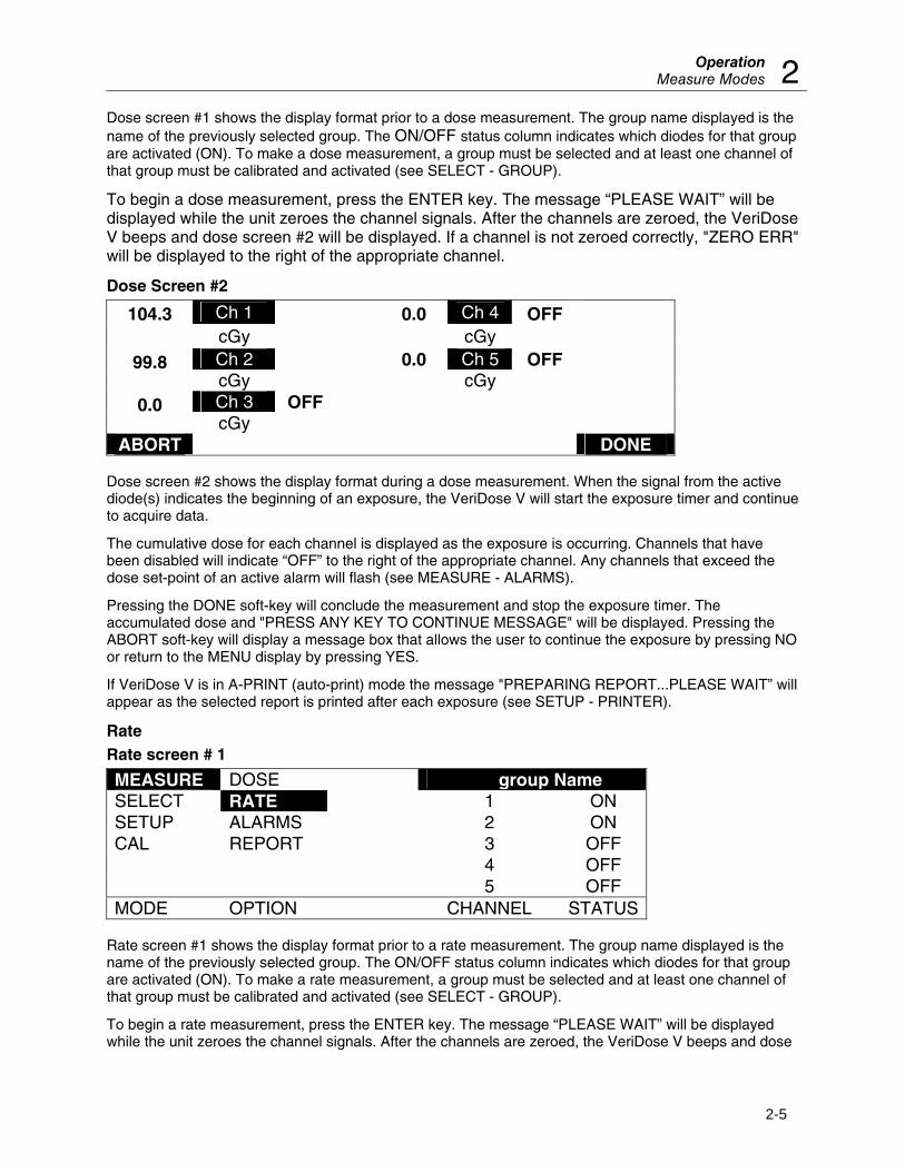
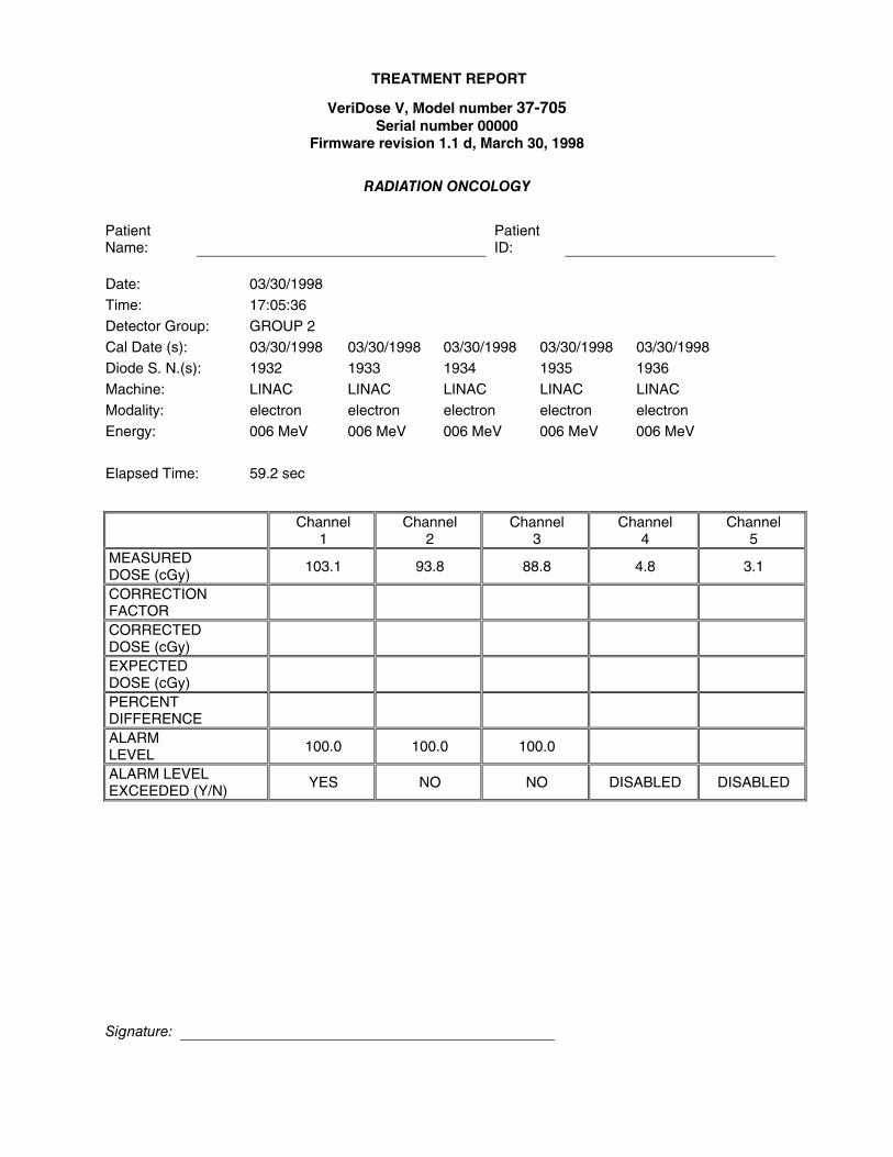
Dose screen #1 shows the display format prior to a dose measurement. The group name displayed is the name of the previously selected group. The ON/OFF status column indicates which diodes for that group are activated (ON). To make a dose measurement, a group must be selected and at least one channel of that group must be calibrated and activated (see SELECT - GROUP).
To begin a dose measurement, press the ENTER key. The message “PLEASE WAIT” will be displayed while the unit zeroes the channel signals. After the channels are zeroed, the VeriDose V beeps and dose screen #2 will be displayed. If a channel is not zeroed correctly, "ZERO ERR" will be displayed to the right of the appropriate channel.
Dose Screen #2
Ch 1 0.0 Ch 4 OFF 104.3 cGy cGy Ch 2 0.0 Ch 5 OFF 99.8 cGy cGy Ch 3 OFF 0.0 cGy
ABORT DONE Dose screen #2 shows the display format during a dose measurement. When the signal from the active diode(s) indicates the beginning of an exposure, the VeriDose V will start the exposure timer and continue to acquire data.
The cumulative dose for each channel is displayed as the exposure is occurring. Channels that have been disabled will indicate “OFF” to the right of the appropriate channel. Any channels that exceed the dose set-point of an active alarm will flash (see MEASURE - ALARMS).
Pressing the DONE soft-key will conclude the measurement and stop the exposure timer. The accumulated dose and "PRESS ANY KEY TO CONTINUE MESSAGE" will be displayed. Pressing the ABORT soft-key will display a message box that allows the user to continue the exposure by pressing NO or return to the MENU display by pressing YES.
If VeriDose V is in A-PRINT (auto-print) mode the message "PREPARING REPORT...PLEASE WAIT” will appear as the selected report is printed after each exposure (see SETUP - PRINTER).
Rate Rate screen # 1
MEASURE DOSE group Name SELECT RATE 1 ON SETUP ALARMS 2 ON CAL REPORT 3 OFF 4 OFF 5 OFF MODE OPTION CHANNEL STATUS
Rate screen #1 shows the display format prior to a rate measurement. The group name displayed is the name of the previously selected group. The ON/OFF status column indicates which diodes for that group are activated (ON). To make a rate measurement, a group must be selected and at least one channel of that group must be calibrated and activated (see SELECT - GROUP).
To begin a rate measurement, press the ENTER key. The message “PLEASE WAIT” will be displayed while the unit zeroes the channel signals. After the channels are zeroed, the VeriDose V beeps and dose
Nuclear Associates 37-705 Operators Manual
2-6
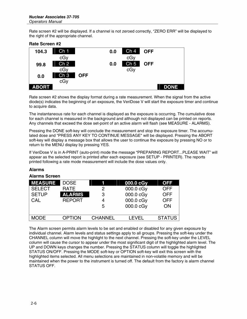
Rate screen #2 will be displayed. If a channel is not zeroed correctly, “ZERO ERR” will be displayed to the right of the appropriate channel.
Rate Screen #2
Ch 1 0.0 Ch 4 OFF 104.3 cGy cGy Ch 2 0.0 Ch 5 OFF 99.8 cGy cGy Ch 3 OFF 0.0 cGy
ABORT DONE Rate screen #2 shows the display format during a rate measurement. When the signal from the active diode(s) indicates the beginning of an exposure, the VeriDose V will start the exposure timer and continue to acquire data.
The instantaneous rate for each channel is displayed as the exposure is occurring. The cumulative dose for each channel is measured in the background and although not displayed can be printed on reports. Any channels that exceed the dose set-point of an active alarm will flash (see MEASURE - ALARMS).
Pressing the DONE soft-key will conclude the measurement and stop the exposure timer. The accumu-lated dose and "PRESS ANY KEY TO CONTINUE MESSAGE" will be displayed. Pressing the ABORT soft-key will display a message box that allows the user to continue the exposure by pressing NO or to return to the MENU display by pressing YES.
If VeriDose V is in A-PRINT (auto-print) mode the message “PREPARING REPORT...PLEASE WAIT” will appear as the selected report is printed after each exposure (see SETUP - PRINTER). The reports printed following a rate mode measurement will include the dose values only.
Alarms Alarms Screen
MEASURE DOSE 1 000.0 cGy OFF SELECT RATE 2 000.0 cGy OFF SETUP ALARMS 3 000.0 cGy OFF CAL REPORT 4 000.0 cGy OFF 5 000.0 cGy ON MODE OPTION CHANNEL LEVEL STATUS
The Alarm screen permits alarm levels to be set and enabled or disabled for any given exposure by individual channel. Alarm levels and status settings apply to all groups. Pressing the soft-key under the CHANNEL column will move the highlight to the next channel. Pressing the soft-key under the LEVEL column will cause the cursor to appear under the most significant digit of the highlighted alarm level. The UP and DOWN keys changes the number. Pressing the STATUS column will toggle the highlighted STATUS ON/OFF. Pressing the MODE soft-key or OPTION soft-key will exit this screen with the highlighted items selected. All menu selections are maintained in non-volatile memory and will be maintained when the power to the instrument is turned off. The default from the factory is alarm channel STATUS OFF.
OperationMeasure Modes 2
2-7
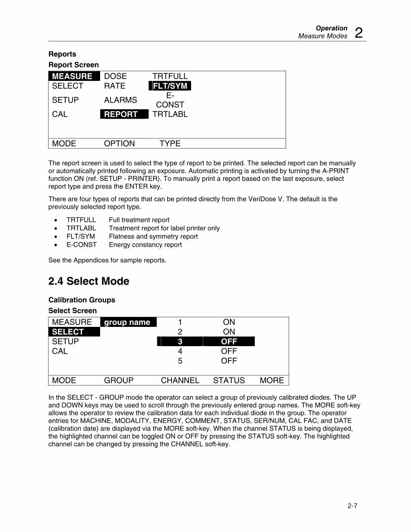
Reports Report Screen
MEASURE DOSE TRTFULL SELECT RATE FLT/SYM
SETUP ALARMS E-CONST
CAL REPORT TRTLABL MODE OPTION TYPE
The report screen is used to select the type of report to be printed. The selected report can be manually or automatically printed following an exposure. Automatic printing is activated by turning the A-PRINT function ON (ref. SETUP - PRINTER). To manually print a report based on the last exposure, select report type and press the ENTER key.
There are four types of reports that can be printed directly from the VeriDose V. The default is the previously selected report type.
• TRTFULL Full treatment report • TRTLABL Treatment report for label printer only • FLT/SYM Flatness and symmetry report • E-CONST Energy constancy report
See the Appendices for sample reports.
2.4 Select Mode
Calibration Groups Select Screen
MEASURE group name 1 ON SELECT 2 ON SETUP 3 OFF CAL 4 OFF 5 OFF MODE GROUP CHANNEL STATUS MORE
In the SELECT - GROUP mode the operator can select a group of previously calibrated diodes. The UP and DOWN keys may be used to scroll through the previously entered group names. The MORE soft-key allows the operator to review the calibration data for each individual diode in the group. The operator entries for MACHINE, MODALITY, ENERGY, COMMENT, STATUS, SER/NUM, CAL FAC, and DATE (calibration date) are displayed via the MORE soft-key. When the channel STATUS is being displayed, the highlighted channel can be toggled ON or OFF by pressing the STATUS soft-key. The highlighted channel can be changed by pressing the CHANNEL soft-key.
Nuclear Associates 37-705 Operators Manual
2-8
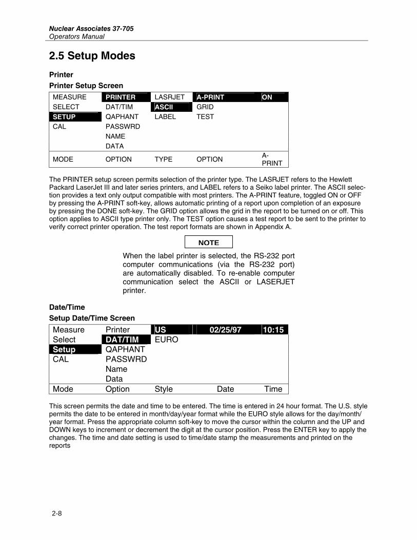
2.5 Setup Modes
Printer Printer Setup Screen
MEASURE PRINTER LASRJET A-PRINT ON SELECT DAT/TIM ASCII GRID
SETUP QAPHANT LABEL TEST CAL PASSWRD NAME DATA
MODE OPTION TYPE OPTION A-PRINT
The PRINTER setup screen permits selection of the printer type. The LASRJET refers to the Hewlett Packard LaserJet III and later series printers, and LABEL refers to a Seiko label printer. The ASCII selec-tion provides a text only output compatible with most printers. The A-PRINT feature, toggled ON or OFF by pressing the A-PRINT soft-key, allows automatic printing of a report upon completion of an exposure by pressing the DONE soft-key. The GRID option allows the grid in the report to be turned on or off. This option applies to ASCII type printer only. The TEST option causes a test report to be sent to the printer to verify correct printer operation. The test report formats are shown in Appendix A.
When the label printer is selected, the RS-232 port computer communications (via the RS-232 port) are automatically disabled. To re-enable computer communication select the ASCII or LASERJET printer.
Date/Time Setup Date/Time Screen
Measure Printer US 02/25/97 10:15Select DAT/TIM EURO Setup QAPHANT CAL PASSWRD Name Data Mode Option Style Date Time
This screen permits the date and time to be entered. The time is entered in 24 hour format. The U.S. style permits the date to be entered in month/day/year format while the EURO style allows for the day/month/ year format. Press the appropriate column soft-key to move the cursor within the column and the UP and DOWN keys to increment or decrement the digit at the cursor position. Press the ENTER key to apply the changes. The time and date setting is used to time/date stamp the measurements and printed on the reports
NOTE
OperationQA Phantom 2
2-9
2.6 QA Phantom
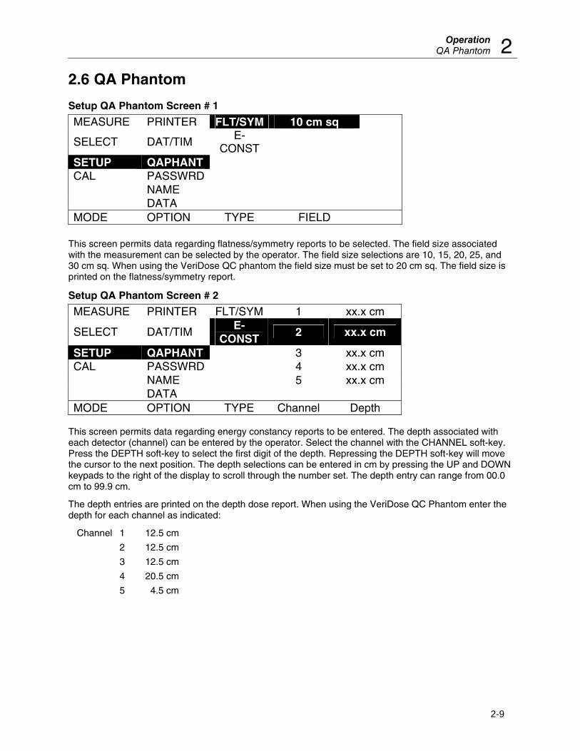
Setup QA Phantom Screen # 1
MEASURE PRINTER FLT/SYM 10 cm sq
SELECT DAT/TIM E-CONST
SETUP QAPHANT CAL PASSWRD NAME DATA MODE OPTION TYPE FIELD
This screen permits data regarding flatness/symmetry reports to be selected. The field size associated with the measurement can be selected by the operator. The field size selections are 10, 15, 20, 25, and 30 cm sq. When using the VeriDose QC phantom the field size must be set to 20 cm sq. The field size is printed on the flatness/symmetry report.
Setup QA Phantom Screen # 2
MEASURE PRINTER FLT/SYM 1 xx.x cm
SELECT DAT/TIM E-
CONST 2 xx.x cm
SETUP QAPHANT 3 xx.x cm CAL PASSWRD 4 xx.x cm NAME 5 xx.x cm DATA MODE OPTION TYPE Channel Depth
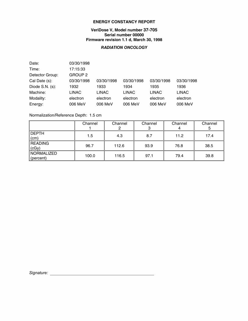
This screen permits data regarding energy constancy reports to be entered. The depth associated with each detector (channel) can be entered by the operator. Select the channel with the CHANNEL soft-key. Press the DEPTH soft-key to select the first digit of the depth. Repressing the DEPTH soft-key will move the cursor to the next position. The depth selections can be entered in cm by pressing the UP and DOWN keypads to the right of the display to scroll through the number set. The depth entry can range from 00.0 cm to 99.9 cm.
The depth entries are printed on the depth dose report. When using the VeriDose QC Phantom enter the depth for each channel as indicated:
Channel 1 12.5 cm
2 12.5 cm
3 12.5 cm
4 20.5 cm
5 4.5 cm
Nuclear Associates 37-705 Operators Manual
2-10
Password Setup Password screen
MEASURE PRINTER AAAA AAAA SELECT DAT/TIM SETUP QAPHANT CAL PASSWRD NAME DATA MODE OPTION OLD NEW
This screen permits the operator to change the security password. The operator must enter the existing password and a new password. The password is a 4 character, alpha-numeric entry. Press the OLD or NEW soft-key to activate the column, and use the UP and DOWN keys to advance to the appropriate character. Press the OLD or NEW soft-key to move the cursor to the next character position. Pressing the ENTER key will save the password entry. The factory default password is AAAA.
Institution Name Setup Name Screen
MEASURE PRINTER AAAAAAAAAAAAAAAAAAAAAAASELECT DAT/TIM SETUP QAPHANT CAL PASSWRD NAME DATA MODE OPTION ENTER INSTITUTION NAME
This screen permits the operator to enter an institution name of up to 23, alpha-numeric characters. Select the ENTER INSTITUTION NAME soft-key and use the UP and DOWN keys to advance to the appropriate character. Press the ENTER INSTITUTION NAME soft-key to move the cursor to the next character position. The institution name is printed on the reports.
Data Format Setup Data screen
MEASURE PRINTER US
SELECT DAT/TIM EURO
SETUP QAPHANT
CAL PASSWRD
NAME
DATA
MODE OPTION STYLE This screen permits the operator to select the data format as US or European. The US format provides decimal points for the data while the EURO format provides commas in place of the decimal points. Press the STYLE soft-key scroll to the appropriate format.
OperationCalibrate Modes 2
2-11
2.7 Calibrate Modes
Calibrate Screen #1
MEASURE AAAA
SELECT
SETUP
CAL
MODE PASSWRD The operator must enter the security password in order to access the calibration features of VeriDose. Enter the correct, 4 digit, alpha-numeric password and press the ENTER key (see SETUP - PASSWORD).
Add A Group Calibrate Screen # 2
MEASURE ADD AAAAAAA
SELECT EDIT
SETUP DELETE
CAL EXPOSE
REPORT
MODE OPTION NAME
The ADD option allows the operator to add new groups to the calibration data base. Up to 25 groups of detectors, each with unique calibration factors, may be entered into the data base. The group name is used as a unique identifier for a set of diodes that are to be calibrated and later recalled for subsequent measurements. The operator may enter up to 7 alpha-numeric characters as indicated by the AAAAAAA field. Select ADD in the OPTION column. Press the NAME soft-key to select the first character of the name. Repressing the NAME soft-key will move the cursor to the next character position. Enter the group name by pressing the UP and DOWN key pads to the right of the display to scroll through the character set. After the name has been entered press the ENTER key.
Nuclear Associates 37-705 Operators Manual
2-12
Calibrate Screen #3
group name
1 NO SER NUM AAAAAAA
2 Yes MODALITY ELECTRON 3 ENERGY 000 4 MACHINE AAAAAAA 5 COMMENT AAAAAAA GROUP CHANNEL DIODE OPTION
After entering a new group name the items in the database are displayed. Each group may include from one to five diodes. The operator must activate each channel individually, assign a diode to that channel by selecting YES in the diode column, or de-activate the channel by selecting NO. The database information regarding each diode in the set is displayed along the right side of the selected channel. The information is only displayed for active diodes (indicated by YES in the diode column).
The SER/NUM entry allows the operator to record the serial number of the diode for the selected channel. The MODALITY (modality) entries, selected by the scroll UP and scroll DOWN key, include ELECTRON, PHOTON and CO60. The energy entry allows the operator to enter the target energy for the selected diode (the energy at which the diode is calibrated). The machine entry may contain the name of the machine used with the selected diode. The comments field may be used to enter a 7-character alphanu-meric comment regarding the selected diode. The entries in the database are printed in various reports for record keeping purposes.
Entering the Database Information:
1. Each channel that has a diode connected must be activated by scrolling to each individual channel number in the second column and selecting YES in the third column. The fourth column displays the database items and fifth column allows the user to enter the identifiers for each of these items. The database items are printed on each report for record keeping purposes.
2. Select channel 1 and enter the Serial number of the diode connected to channel 1. Press the soft-key below column 5 to scroll the cursor to the right and use the UP and DOWN keys to the right of the display to enter the appropriate serial number. A blank space can be entered by scrolling down from "A".
3. Press the OPTION soft-key (column 4) to select the Modality item. Press the soft-key below column 5 and use the UP and DOWN keys to the right of the display to enter the appropriate modality label.
4. Press the OPTION soft-key (column 4) to select the Energy item. Press the soft-key below column 5 to scroll the cursor to the right and use the UP and DOWN keys to the right of the display to enter the appropriate energy.
5. Press the OPTION soft-key (column 4) to select the Machine item. Press the soft-key below column 5 to scroll the cursor to the right and use the UP and DOWN keys to the right of the display to enter the appropriate machine label. A blank space can be entered by scrolling down from "A".
6. Press the OPTION soft-key (column 4) to select the Comment item. Press the soft-key below column 5 to scroll the cursor to the right and use the UP and DOWN keys to the right of the display to enter the appropriate comment. A blank space can be entered by scrolling down from "A".
7. Repeat this process for each channel that has a diode connected by pressing the column 2 soft-key to access the related database items.
OperationCalibrate Modes 2
2-13
Calibrate Screen # 4
group name 1 NO SER NUM AAAAAAA
2 Yes MODALITY ELECTRON 3 ENERGY 000 4 MACHINE AAAAAAA 5 SAVE CHANGES TO group name? GROUP CHANNEL DIODE YES NO
After completing the entry of all the database information press the ENTER key. Press the YES key (column 4) to save the database information.
Edit an Existing Group Calibrate Screen # 5
MEASURE ADD group name
SELECT EDIT SETUP DELETE CAL EXPOSE REPORT MODE OPTION GROUP
The EDIT option may be used to edit the database for the selected group. After selecting the EDIT option, the operator may scroll through the existing groups by pressing the GROUP soft-key and pressing the UP or DOWN key pads to the right of the display to scroll through the group names. After the group has been selected press the ENTER key.
Calibrate Screen #6
group name
NO SER NUM AAAAAAA
2 Yes MODALITY ELECTRON 3 ENERGY 000 4 MACHINE AAAAAAA 5 COMMENT AAAAAAA GROUP CHANNEL DIODE OPTION
After selecting the group to be edited, the items in the database are displayed. The operator may activate each channel individually, assign a diode to that channel by selecting YES in the diode column, or de-activate the channel by selecting NO. The database information regarding each diode in the set is dis-played along the right side of the selected channel. The information is only displayed for active diodes (indicated by YES in the diode column).
The SER/NUM entry allows the operator to record the serial number of the diode for the selected channel. The MODALITY (modality) entries, selected by the scroll up and scroll down key, include ELECTRON, PHOTON and CO60. The ENERGY entry allows the operator to enter the target energy for the selected diode (the energy at which the diode is calibrated). The MACHINE entry may contain the name of the
Nuclear Associates 37-705 Operators Manual
2-14
machine used with the selected diode. The COMMENTS field may be used to enter a 7-character alpha-numeric comment regarding the selected diode. The entries in the database are printed in various reports for record keeping purposes.
Entering the Database Information:
1. Each channel that has a diode connected must be activated by scrolling to each individual channel number in the second column and selecting YES in the third column. The fourth column displays the database items and fifth column allows the user to enter the identifiers for each of these items. The database items are printed on each report for record keeping purposes.
2. Select channel 1 and enter the Serial number of the diode connected to channel 1. Press the soft-key below column 5 to scroll the cursor to the right and use the UP and DOWN keys to the right of the display to enter the appropriate serial number. A blank space can be entered by scrolling down from "A".
3. Press the OPTION soft-key (column 4) to select the Modality item. Press the soft-key below column 5 and use the UP and DOWN keys to the right of the display to enter the appropriate modality label.
4. Press the OPTION soft-key (column 4) to select the Energy item. Press the soft-key below column 5 to scroll the cursor to the right and use the UP and DOWN keys to the right of the display to enter the appropriate energy.
5. Press the OPTION soft-key (column 4) to select the Machine item. Press the soft-key below column 5 to scroll the cursor to the right and use the UP and DOWN keys to the right of the display to enter the appropriate machine label. A blank space can be entered by scrolling down from "A".
6. Press the OPTION soft-key (column 4) to select the Comment item. Press the soft-key below column 5 to scroll the cursor to the right and use the UP and DOWN keys to the right of the display to enter the appropriate comment. A blank space can be entered by scrolling down from "A".
7. Repeat this process for each channel that has a diode connected by pressing the column 2 soft-key to access the related database items.
Calibrate Screen # 7
group name
NO SER NUM AAAAAAA
2 YES MODALITY ELECTRON 3 ENERGY 000 4 MACHINE AAAAAAA 5
SAVE CHANGES TO group name?
GROUP CHANNEL DIODE YES NO After completing the entry of all the data base information press the ENTER key. Press the YES key (column 4) to save the database information.
OperationCalibrate Modes 2
2-15
Delete a Group Calibrate Screen # 8
MEASURE ADD group name
SELECT EDIT SETUP DELETE CAL EXPOSE REPORT MODE OPTION GROUP
The DELETE option allows the operator to delete an existing group. To delete a group from the group database select the GROUP soft-key and press the scroll up or scroll down key to review the groups. Once the appropriate group has been selected press the ENTER key.
Calibrate Screen # 9
MEASURE ADD group name
SELECT EDIT
SETUP DELETE
CAL EXPOSE
REPORT
DELETE group name
ARE YOU SURE? MODE OPTION GROUP YES No
To delete the selected group, press the YES soft-key, to abort the delete process press the NO soft-key.
Making a Calibration Exposure – Calibrate Screen # 10
MEASURE ADD group name
SELECT EDIT SETUP DELETE CAL EXPOSE REPORT MODE OPTION GROUP
The EXPOSE option allows the operator to select an existing group and perform a calibration. Select the GROUP soft-key, scroll to the desired group and press the ENTER key.
Nuclear Associates 37-705 Operators Manual
2-16
Calibrate Screen # 11
group name
1 YES
2 YES 3 YES 4 NO 5 N/A GROUP CHANNEL EXPOSE
Prior to initiating a calibration sequence, the operator may select the diodes within a group that will be calibrated. The expose column shows the diode(s) that are to be calibrated by YES and the diode(s) that are not to be calibrated by NO. Any channel(s) that have not been activated by the operator in either the CALIBRATE - ADD or the CALIBRATE - EDIT options are indicated by N/A (not available). After the appropriate selections have been made press the ENTER key.
The message "PLEASE WAIT' will be displayed while the unit zeroes the channel signals. After the chan-nels are zeroed, the VeriDose V beeps and Calibrate Screen #12 will be displayed. If a channel is not zeroed correctly, "ZERO ERR" will be displayed to the right of the appropriate channel. The cumulative dose for each channel is displayed as the exposure is occurring.
Calibrate Screen # 12
Ch 1 0.0 Ch 4 OFF 104.3
cGy cGy Ch 2 0.0 Ch 5 OFF
99.8 cGy cGy Ch 3
55.1 ABORT DONE
Several successive exposures may be averaged (up to 1000 cGy) by simply exposing the detectors to repetitive exposures while the VeriDose V remains in the measurement mode. Upon completion of the exposure(s) the operator may press the DONE soft-key to proceed to the next calibration screen or press the ABORT soft-key to terminate the calibration process. Calibration factors are calculated based on a normalized sensitivity of 1.000 nC/cGy. If the calibration process is interrupted by a machine malfunction it is necessary to re-start the calibration process from the beginning.
Calibrate Screen # 14
1 102.0 100.3 cGy 2 102.1 3 102.3 4 5
GROUP CHANNEL CGY ACTUAL
EXPOSURE The result of each channel is displayed in cGy. Press the ACTUAL EXPOSURE soft-key to select the first digit of the exposure. Repressing the ACTUAL EXPOSURE soft-key will move the cursor to the next digit
OperationCalibrate Modes 2
2-17
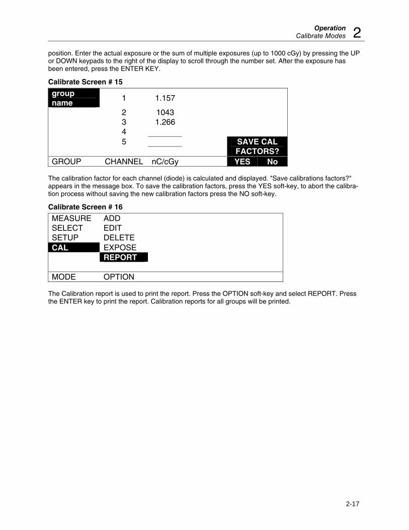
position. Enter the actual exposure or the sum of multiple exposures (up to 1000 cGy) by pressing the UP or DOWN keypads to the right of the display to scroll through the number set. After the exposure has been entered, press the ENTER KEY.
Calibrate Screen # 15
group name
1 1.157
2 1043 3 1.266 4 5
SAVE CAL FACTORS?
GROUP CHANNEL nC/cGy YES No The calibration factor for each channel (diode) is calculated and displayed. "Save calibrations factors?" appears in the message box. To save the calibration factors, press the YES soft-key, to abort the calibra-tion process without saving the new calibration factors press the NO soft-key.
Calibrate Screen # 16
MEASURE ADD
SELECT EDIT
SETUP DELETE
CAL EXPOSE
REPORT MODE OPTION
The Calibration report is used to print the report. Press the OPTION soft-key and select REPORT. Press the ENTER key to print the report. Calibration reports for all groups will be printed.
Nuclear Associates 37-705 Operators Manual
(Blank Page)
VeriDose QC PhantomGeneral Description 3
3-1
Section 3 VeriDose QC Phantom
3.1 General Description
The VeriDose QC Phantom is a device that, in conjunction with the VeriDose V and the VeriDose Excel Add-In, may be used for daily QC checks performed on radiation therapy machines (linear accelerators). The VeriDose QC utilizes five VeriDose diodes positioned in an acrylic phantom to measure beam con-stancy, flatness, symmetry and provide a depth dose check.
The VeriDose QC Phantom is configured for use in a standard 20 x 20 cm field. One detector is positioned at the central axis and four detectors are positioned at 8 cm off the central axis in both the X and Y axis (80% of field size).
The phantom may be positioned on its edge with detector +Y closest to the gantry for depth dose mea-surements. In this mode detector +Y is located at a depth of 4.5 cm, detectors -X, central axis and +X are located at a depth of 12.5 cm, and detector -Y is located at a depth of 20.5 cm.
The VeriDose QC Phantom is connected to the VeriDose V with a 15 m cable. The VeriDose V provides a Flatness and Symmetry Report and an Energy Constancy (depth dose) Report based on the measure-ment results using the QC Phantom. For further description of these features refer to the Setup Modes QA Phantom section of the manual.
In addition, the measurement results may be accessed by a PC operating under the VeriDose Excel Add-In. Graphs of beam constancy, flatness, symmetry and depth dose check are automatically generated. For further description of these features refer to the VeriDose Excel Add-In manual (P/N VERIDOSEXL--1).
3.2 VeriDose QC Phantom Specifications
Detector 5 diode detectors
Energy Range Photon: 4 to 25 MV Electron: 5 to 25 Mev
Sensitive Volume 0.25 mm3
Sensitivity 1.5 nC/cGy
Diode Polarity Negative
Rad damage @ 10 kGy < 15%
Operating Temperature 10°C to 40°C (50°F to 104°F)
Relative Humidity 5 to 95%, non-condensing
Nuclear Associates 37-705 Operators Manual
3-2
Detector configuration
Flatness/Symmetry One central axis (Horizontal orientation) Four - orthogonally positioned at 8 cm off central axis in the transverse
and radial planes. Off-axis detectors are positioned at 80% of field size for flatness and
symmetry measurements.
Energy constancy Detector depth positions: 4.5, 12.5, 20.5 cm (Vertical orientation)
Interface Cable 50 ft (15 m) P/N 37-705-7300
Build-up 1.9 cm acrylic (2.3 g/cm2)
Size 9.85 (w) x 9.85 (d) x 1.5 in (h) (25 x 25 x 3.8 cm)
Weight 5.25 lbs (11.6 kg)
3.3 Connection to the VeriDose V
Connect the VeriDose QC Phantom cable to the phantom and the VeriDose V as indicated:
Channel 1 Central axis Yellow
Channel 2 -X Red
Channel 3 +X Green
Channel 4 -Y Blue
Channel 5 +Y White
3.4 Setup
Refer to the Setup Mode - QA Phantom section of the manual for detailed instructions regarding setup parameters for the VeriDose QC Phantom.
3.5 Calibration
It is the responsibility of the user to calibrate the VeriDose system. It is recommended that the VeriDose QC Phantom be calibrated under the conditions that represent normal daily use. Since the calibration process will associate a particular detector to a specific channel on the VeriDose V, it is necessary to connect the device properly (as indicated in the Connecting to the VeriDose V section) for the calibration process as well as for subsequent measurements.
Reference the VeriDose Calibrate Modes section of the manual for a complete description of the calibra-tion functions. Two methods of calibrating the VeriDose QC Phantom are described below:
Method 1 Calibrate all 5 detectors (channels) individually, centering each detector on the central axis at 100 cm SSD. Place build-up material equal to or greater than Dmax depth over the detector. Use a small field size of 5 x 5 cm and irradiate to a known calibration dose. Repeated exposures are recommended for dose averaging, with a maximum cumulative dose of less than 1000 cGy.
Verify the calibration process by setting the recommended 20 x 20 cm field size and aligning the QC Phantom's central diode with the central ray. Place calibration build-up over the entire phantom. Beam
VeriDose QC PhantomGeneral Description 3
3-3
flatness and symmetry should be within the approximate tolerances as specified by AAPM guidelines (TG-40).
Method 2 Calibrate all the detectors at the same time by aligning the QC Phantom's central diode with the central ray. Set the 20 x 20 cm field size and align to the field outline on the QC Phantom. Set the distance to 100 cm SSD to the phantom surface and place build-up material equal to or greater than Dmax depth over the entire phantom. Irradiate the phantom to a known calibration dose. Repeated exposures are recommended for dose averaging, with a maximum cumulative dose of less than 1000 cGy. Note that this method will yield a reference value of 0.0%, for flatness and symmetry, to be used only as QA baseline values. These baseline reference values for flatness and symmetry will be relative to the actual values at the time of calibration, therefore, special attention must be paid to setting correct tolerance levels. Initial values for flatness and symmetry must be factored into the pass/fail criteria of the beam to conform to AAPM guidelines (TG-40).
Calibrate each detector (channel), one at a time, positioned at isocenter. A typical exposure of 100 - 200 cGy at a dose rate of 100 to 300 cGy/min is adequate for calibration. Upon completion of the calibration process, several additional exposures should be made in the normal measurement mode in order to verify the calibration. To print the results, select the Flatness/Symmetry report on the VeriDose V.
3.6 Flatness and Symmetry Measurements
Position the VeriDose QC Phantom flat on the treatment table. Position the central axis chamber at isocenter and align the X and Y crosshairs with the laser positioning system. Collimate the field size to 20 x 20 cm using the borders on the QC Phantom as a guide. To make measurements, follow the procedure outlined in the VeriDose V Measure Modes - Dose section of the manual. A Flatness and Symmetry Report may be printed by selecting the appropriate report in the Measure Reports menu and pressing the ENTER key.
3.7 Depth Dose check
Position the VeriDose QC Phantom on its edge with Y + positioned closest to the gantry. Additional build-up may be placed against the sides of the phantom. Position the central axis chamber at isocenter and align the X and Y crosshairs with the laser positioning system. Collimate the field size to 20 x 20 cm. To make measurements, follow the procedure outlined in the VeriDose V Measure Modes - Dose section of the manual. A Depth Dose Report may be printed by selecting the appropriate report in the Measure Reports menu and pressing the ENTER key.
Nuclear Associates 37-705 Operators Manual
(Blank Page)
AppendixReports A
A-1
Appendix A Reports
See the following pages.
FLATNESS/SYMMETRY REPORT
VeriDose V, Model number 37-705 Serial number 00000 Firmware revision 1.1 d, March 30, 1998
RADIATION ONCOLOGY
Date: 03/30/1998 Time: 17:36:34 Detector Group: GROUP 2 Calibration Date(s): 03/30/1998 03/30/1998 03/30/1998 03/30/1998 03/30/1998 Diode Serial Numbers:
1932 1933 1934 1935 1936
Machine: LINAC LINAC LINAC LINAC LINAC Modality: electron electron electron electron electron Energy: 006 MeV 006 MeV 006 MeV 006 MeV 006 MeV Field Size: 10.0 cm x 10.0 cm
VeriDose V, Model number 37-705 Serial number 00000
Firmware revision 1.1 d, March 30, 1998
RADIATION ONCOLOGY
Date: 03/30/1998 Time: 17:36:34 Detector Group: GROUP 2 Cal Date (s): 03/30/1998 03/30/1998 03/30/1998 03/30/1998 03/30/1998 Diode S. N. (s): 1932 1933 1934 1935 1936 Machine: LINAC LINAC LINAC LINAC LINAC Modality: electron electron electron electron electron Energy: 006 MeV 006 MeV 006 MeV 006 MeV 006 MeV Field Size: 10.0 cm x 10.0 cm
Channel 1
Channel 2
Channel 3
Channel 4
Channel 5
MEASURED DOSE (cGy) 109.6 109.9 110.2 109.8 110.5 POSITION ASSIGNMENT Center -X +X -Y +Y RATIO 1.000 1.003 1.006 1.002 1.008
Machine: LINAC LINAC LINAC LINAC LINAC Modality: electron electron electron electron electron Energy: 006 MeV 006 MeV 006 MeV 006 MeV 006 MeV Normalization/Reference Depth: 1.5 cm
VeriDose V, Model number 37-705 Serial number 00000
Firmware revision 1.1 d, March 30, 1998
RADIATION ONCOLOGY
Detector Group: GROUP 2
Channel 1
Channel 2
Channel 3
Channel 4
Channel 5
SERIAL NUMBER
1932 1933 1934 1935 1936
CALIBRATION FACTOR
1.152 1.244 1.176 1.226 1.205
MACHINE LINAC LINAC LINAC LINAC LINAC
ENERGY 006 006 006 006 006
MODALITY electron electron electron electron electron
CALIBRATION DATE 03/30/1998 03/30/1998 03/30/1998 03/30/1998 03/30/1998
Signature:
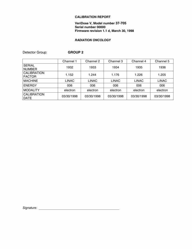
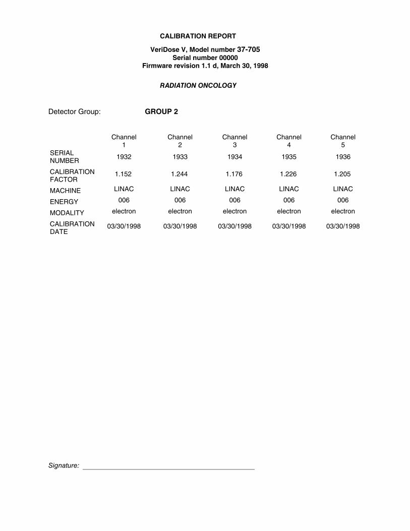
CALIBRATION REPORT
VeriDose V, Model number 37-705 Serial number 00000
Firmware revision 1.1 d, March 30, 1998
RADIATION ONCOLOGY
Detector Group: GROUP 2
Channel 1
Channel 2
Channel 3
Channel 4
Channel 5
SERIAL NUMBER 1932 1933 1934 1935 1936
CALIBRATION FACTOR
1.152
1.244
1.176
1.226
1.205
MACHINE LINAC LINAC LINAC LINAC LINAC
ENERGY 006 006 006 006 006
MODALITY electron electron electron electron electron
CALIBRATION DATE
03/30/1998
03/30/1998
03/30/1998
03/30/1998
03/30/1998
Signature:
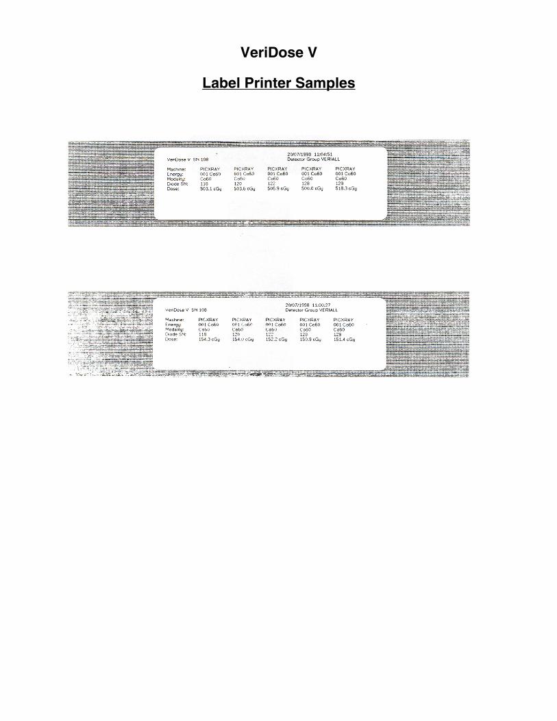
VeriDose V
Label Printer Samples
ASCII Printer Test Page…
Complete (8-bi) character set…
Grid Test
If the above Grid Test is comprised of single and double lines, then the GRID option should be ON.
If the above Grid Test shows special symbols or accented alphabetic characters, then the GRID option should be OFF. Note: With some printers, you may be able to select a default character set that includes line drawing characters.
The ACSII printer GRID is currently ON.
Column positioning test…
VeriDose V
Label Printer Test Label
Roman-8, Proportional, 12 pt, Times Typeface…
Margin test…
Superscript/Subscript test…
LaserJet Printer Test Page…
(Blank page)
AppendixError Messages B
B-1
Appendix B Error Messages
Checksum error 0x06FF
1.
PRESS ANY KEY TO CONTINUE…
If the above message appears, note the error code and call Fluke Biomedical Technical Support at 440.248.9300.
18 Calibration groups were
reset due to checksum errors
2.
PRESS ANY KEY TO CONTINUE…
The above message indicates that internal RAM error occurred during startup. Restart the unit to verify reset.
RS-232 timed out
3.
PRESS ANY KEY TO CONTINUE…
The above message indicates that the communications has timed out. Verify the serial cable is secured at both ends. Restart the unit.
Group with this
name already exists. Please select a different name.
4.
PRESS ANY KEY TO CONTINUE…
The above message appears when the name you have entered already exists. Enter a different name and continue.
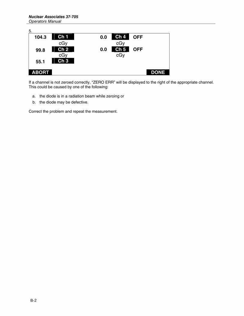
If a channel is not zeroed correctly, “ZERO ERR” will be displayed to the right of the appropriate channel. This could be caused by one of the following:
a. the diode is in a radiation beam while zeroing or
b. the diode may be defective. Correct the problem and repeat the measurement.