• • • Nlr r o Offi 11 • 1982 4410-82-L-46 At: . L. H. rett, puty Pro ector sion c/o Mile Isld Stati Middlet, PA 17057-0191 Sir: GPU Nle Ca Post Olhce Bo 480 Route 441 South Middletown, Pennsytvan1a 17057 717 944·7621 TELEX 84·2386 Wutef's 011ect 01al Number· e le Isl Stati, lit 2 -2) rat . D-73 t . 50-320 ral oject si iteria Attacהd f foti is a y of isi 3 al Pject si iteria. Inated in this risi e resoluti ts p isi 1 to al oject si+ iteria � re lett -82-0I8 ted ril 1, 1982. isi 2 al Project si Criteria rated ral int ts d t prid of srt פri is of isi 2 ision 3. If sti, plee tact . J. J. B of Ä staff. r K/JJB/ je p Attat Ì: . B. J. yr, Dect - Offi O � · J ... ,.. � > O c no � o �� . 4 c � R11170218 R1111 PDR �DK 032 0 p PDR (H Q � GPU Nuclear Corratton •s a sustcary ot the Gcnerill Pultc Ultltl•es Co1po1a11on
Transcript
• • •
Nuclear
n-rr Progran Office
Naverrber 11 • 1982 4410-82-L-0046
Attn: Mr. L. H. Barrett, Deputy Progran Director US Nuclear Regulatory Carmission c/o 'lllree Mile Island Nuclear Station Middletown, PA 17057-0191
Attached for your infonmti.on and use is a copy of Revision 3 to tb! General Project Design Criteria. Incorporated in this revision are resolutions to NRC caments provided on Revision 1 to tb! General Project DesiJ111 Criteria �ch were provided to CPU via NRC letter NRCfiMI-82-0I8 dated April 1, 1982. Revision 2 to tb! General Project Design Criteria incorporated several internal CPU c:anrents and was rot provided to the NRC because of the short tine period between the issuance of Revision 2 and Revision 3.
If you have any further questions, please contact Mr. J. J. Byrne of my C4 staff. C> r
BKK/JJB/jep
Attachnent
CC: Dr. B. J. Snyder, Progran Director - 'IMI Progran Office
"t)O
� :t· J.S ... .::') :;o: ,... � >'=
O!-n Vi :D:z:
-<c no
� or-�� ...... 4
\0 c. �
8211170218 821111 PDR �DOCK 0'<>00320 p PDR
(H Q �.!
GPU Nuclear Corporatton •s a sut>stc.ltary ot the Gcnerill Put>ltc Ultltl•es Co1po1a11on
( 3.5 Industry Codes and Standards 8 3.6 Safety Assessment 8
4.0 ALARA DESIGN CRITERIA AND CONSIDERATIONS 9 lz Table 1 Regulatory Guldes 10 12 Table 2 ALARA Items 15 Table 3 Typical Radioactive Piping Classification
and Routing . 34 1
2 • Table 4 Radiation 'Zones 35
Rev. 2
...._ __________ ___;,;;. _ __;_ _______ __ ·-
Design Criteria 13587-2-L01-100
1.0 GENERAL
1.1 INTRODUCTION
1. !.1 This design criteria is applicable only to those facilities and activities for which Bechtel has design responsibility.
1.1.2 This section of the General Project Design Criteria contains information common to all disciplines.
1.1.3 The General Project Design Criteria is applicable to facilities designed by Bechtel for the THI-2 recovery effort. The criteria presented herein are not applicable to the rebuilding of the unit for power generation. The General Project Design Criteria is to be applied to each facility by reference in each facility's specific design criteria document. Any conflicts between the general and specific criteria must be ident�fied in the specific design criteria document.
1.1.4 Existing plant systems interfacing recovery systems need not be upgraded to current codes and standards applicable to the recovery systems and associated tie-ins.
1.1.5 Recovery project designs pertaining to systems, structures, and components classified as safety related or important to safety shall incorporate pertinent requirements from applicable NRC Regulatory Guides listed in the Project Nuclear Quality Assurance Manual. Systems, structures, and components to which the Project Nuclear Quality Assurance Program applies are identified in the Project Q-list, document number 13587-2-G20-100, and the Project NSQ-List, document number 13587-2-G20-101.
1.2 PROJECT OBJECTIVES
1.2.1 There are four main objectives of the THI-2 recovery. These objectives are:
1) Decontaminate the reactor building and equipment contained therein
2) Remove and store the reactor core
3} Decontaminate the Reactor Coolant System
4) Process radioactive waste
1.2.2 In order to achieve these objectives additional facilities and systems will be required. Some of these facilities will be permanent in nature� others will only be for the recovery of the unit and will be removed prior to the unit returning to service.
1.2.3 In addition to the facilities and systems to be provided, there will be plans developed for many of the activities required to achieve the project objectives.
Page 1 Rev. 0
(
Design Criteria 13587-2-L01-100
1.3 PROJECT CONCERNS
1.3.1 There are two major concerns that directly influence the design of the facilities and the operations required for the cleanup of TMI-2. These concerns are:
1) Public health and safety
2) Occupational health and safety
2.0 DEFINITIONS
2.1 SAFE SHUTDOWN EARTHQUAKE (SSE)
The safe shutdown earthquake is that earthquake which is based upon an evaluation of the maximum earthquake potential considering the regional and local geology and seismology and specific characteristics of local subsurface material. It is that earthquake which produces the maximum vibratory ground motion for which certain structures, systems, and components are designed to remain functional.
2.2 OPERATING BASIS EARTHQUAKE (OBE)
The operating basis earthquake is that earthquake which, considering the regional and local geology and seismology and specific characteristics of local subsurface material, could reasonably be expected to affect the plant site during the operating life of tne plant; it is that earthquake which produces the vibratory ground motion for which those features of the nuclear power plant necessary for continued operation without undue risk to the health and safety of the public are designed to remain functional.
2.3 SEISMIC CATEGORY I/NON-SEISHIC CATEGORY I
Seismic Category I structures, systems, and components for seism�c design purposes are defin.ed as those structures, systems, and components important to safety that are designed to remain functional in the event of a safe shutdown earthquake. Items that are both Seismic Category I and im�ortant to safety are those structures, systems, and components:
a. that are permanent plant components necessary to en�ure the integrity of the reactor coolant pressure boundary,
b. that are necessary to ensure the capability to shut down the reactor or to maintain the reactor in a safe shutdown condition (i.e., maintain subcriticality and decay heat removal), or to prevent a condition or event that could result in a return to nuclear criticality of fuel inside or outside the reactor vessel, or
c. whose failure could result in potential offsite exposures comparable to the guideline values of 10 CFR Part 100. (Note: for the purpose of THI-2 recovery only. no events or accidents have been postulated which could result in such offsite
Page 2 Rev. 2
2
Design Criteria 13587-2-L01-100
exposures. Therefore, it is not expected that the guideline values of 10 CFR Part 100 will be invoked for design or 2
- operational-related activities during TMI Unit 2 recovery.)
Non-Sefs•ic Category I structures, systems, and components are those whose failure would not resu:� in the release of radioactivity in excess of 10 CFR 100 limits nor prevent reactor safe shutdown.
2.4 DESIGN BASES
Design bases are postulated events/conditions or combinations of events/ conditions which establish the function and structural requirements of a structure, system, or component.
2.5 SAFETY-RELATED FEATURES
Safety-related features are those permanent plant features necessary to 12 assure the integrity of the reactor coolant pressure boundary, the capability to shut down the reactor and maintain it in a safe shutdown condit Jn, or the capability to prevent or mitigate the consequences of accider.ts which could res�lt in offsite exposures comparable to the guideline exposures of 10 CFR Part 100.
2.6 IMPORTANT TO SAFETY
Features important to safety are those structures, systems, and components that are safety related plus those:
a. Which are employed for radioactive waste management (as defined in Regulatory Guide 1 . 143)
b. Which are required to prevent fires or mitigate the co�sequences of fires in ar�as which contain safety-related components or significant quantities of radioactive materials {N�te 1 )
c. Whose failure during a safe shutdown earthquak� could reduce the functioning of a safety-related plant feature.
3 . 0 LICENSING
3. 1 INTRODUCTION
Recovery operations, activities, and work tasks will be performed within the existing THI-2 Technical Specifications and in accordance with applicable NRC Regulatory Guides. Specific design criteria shall identify applicable Technical Specifications and Regulatory Guide requirements.
Note 1: Oefined as the quantity of radioactive materials which, in case of fire in the facility, could cause an airbornfJ release to the environment which could exceed the limits of 10 CFR Part 20, Appendix 8, Table II, Column 1.
Page 3 Rev. 2
(
Design Criteria 1358'l-2-L01-100
3 . 2 BASIC CRITERIA
3 . 2 . 1 faci l i ties and syste•s constructed to support the recovery sha l l not be designed to requirements based on the hypothes i s of accidents at power.
3 . 2 . 2 Faci l i ties and syste•s constructed for the l i fe of the plant sha l l be designed to the appl icable requi rements speci fied i n Chapter 3 o f the THI-2 FSAR i n addition to the requi rements necessa� for the recove�. The latest appl icable codes and standards wi l l be e.ployed.
3 . 2 . 3 To the extent practicable, faci l i ties and services constructed for the recove� effort wi l l be separate fro� existing faci l i ties and services.
Where it is not practicable to separate the faci l i ties and services constructed for the recove� effort from existing fac i l i ties and services, design requi rements wi l l be imposed as necessary i n order not to compro�fse the original design bases of the existing faci l i ties and services. These requi rements sha l l be identified i n the spec i f i c design criteria for the faci l i ty and service to be provided. The following wi l l serve as guide l i nes:
a. Where piping and cables to be left in place when the unit i s returned to service are routed through buildings containing seismic Catego� I piping and cables, the fai l ure of the nonseismic Category I components sha l l not result i n the fail ure of the sei smic Category I components as a result of a seismic event.
b. Where services to support recove� must tie into exi sting plant services, i solation provi s ions c�ensurate with the design requi rements of the existing plant service sha l l be provided.
.. . . c. · Where p1ping to be lett in pl ace when the uni t i s return��lo
service i s routed through buil dings containing safety-related equipment, the requirements for high energy l i ne break.and pipe whip speci fied i n the THI-2 FSAR sha l l be satisfied as applicable.
d. Where cables to be left in pl ace when the un it is returned to service are routed through buil di ngs containing safety-r.e l ated equipment, the requi rements for separation and f i re protection spec i fied in the THI-2 FSAR and THI-2 Fire Protection Reeval uation sha l l be satisfied as appl icable.
3 . 2 . 4 Faci l i ties constructed to support the recovery effort shal l not have as part of th�lr design bas i s the severe natural phenomena for which the plant was orig1na l ly desi gned. Incl uded under "severe natural phenomena" are:
a. Safe shutaown earthquake
b. Tornad� and tornado missi le
c. Haximu" flood. Page 4 Rev. 2
Des i gn Criteria 13587-2-LOl-100
The fac i l i ties will be designed to ensure that there wi l l be no loss of required function of exi sting adjacent safety-related structures , equipment, or systems should these events occur.
These fac i l ities sha l l be desi gned for the aore probabl e natural phenomena as cal led for by area bui lding code requirements.
3 . 2 . 5 Fac ilities constructed to support the recovery sha l l not be designed for man·•ade events not resul ting from recovery acti v i ties. Incl uded under "aan-ude events not resulting fr011 recovery activ i ties" are:
a . Transportation acc idents occurring offsite
b. Airpl ane crashes
c. Release of toxic chemicals.
The fac i l ities wi l l be designed to ensure that there wi l l be no loss of required function of existing adjacent safety-rel ated structures, equipment, or systems should these events occur.
3 . 2. 6 Environmental analyses wi l l be performed i n accordance with the methodology permi tted by the Three M i l e I s l and Nuclear Generating Station Offsite Dose Calculation Manual (ODCH). The s i te meteorol ogy used for these analyses wi l l be based on that contained i n the ODCM.
3 . 2 . 7 For purposes of design evolution, the ri ver character i stics specified i n Chapter 2 of the TMI-2 FSAR sha l l be used. River water qua l i ty data i s that spec i f i ed i n the Plant Design and Mechanical Des i gn Criteria, 13587-2-H01-100.
3. 3 DESIGN CONDITIONS
Th is sectioQ defines tbe spectra of operating conditions to which the · act1vities required for the recovery sha l l be designed. Also provided are the general design requirements for these operating condi tions.
3. 3 . 1 Condition I - Nonaal Operation
Condition I occurrences are those that can reasonably be expected to occur during the recovery acti vit ies. Examples of Condition I occurrences are:
a. Those that are normal ly expected to occur during the recovery including contamination/decontamination resulting from routine activi ties.
b. Operations with equipment out of service or undergoing tests within operational l imitations.
Condition I occurrences sha l l be accommodated with only routine action required to prevent an unplanned release of radioactive materi a l s in effluents to unrestricted areas.
Page 5 Rev. 3
Design Criteria 13587-Z-L01-100
3.3.2 Condition II - Incidents of Moderate Frequency
Condition II occurrences are those any one of which aay reasonably be expected to occur during a calendar year and which could result in a release of radioactive •aterial requiring additional support personnel and/or equipaent to control. Exuples of Condition II occurrences are:
a. Loss of electrical power
b. Minor leakage fro. systems installed to support the recovery
c. Inadvertent actuation of a single active component in a system installed to support the recove�
d. Single error by an operator engaged in a recoveri activity
e. Single active failure of a co.ponent (taken as the initiating event) in a syste• installed to support the recove�
Condition II occurrences shall be accommodated with, at most, a cessation of activities with the capability of resuming the activities after corrective action. Any release of radioactive aaterials in effluents to unrestricted areas shall be in conformance with Paragraph 20.1 of 10 CFR Part 20, "Standards for Protection Against Radiation."
3.3. 3 Condition III - Infrequent Incidents
Condition III occurrences are those which are not expected to occur but are assumed to occur during the lifetime of the recove� effort and could result in a significant release of radioactive •aterial. Examples of Condition III occurrences are:
a. Rupture of any tank utilized for the recovery effort
b. Pipe preak in a system installed to support the recove�
c. Fire in an area where recove� activities occur
d. An operating basis earthquake (OBE).
e. Fuel handling accident in the reactor building (Note 2).
Condition III occurrences may result in damage to recove� facilities sufficient to preclude resumption of recove� activities for a considerable time. The release of radioactive material in effluents to unrestricted areas may exceed the guidelines of 10 CFR Part 20, "Standards for Protection Against Radiation," but shall not be sufficient to interrupt or restrict public use of those areas beyond the exclusion radius.
Note 2: lhe source �for the postulated occurrence is based on assuming the assembly �ith the peak invento� of �adioactive material in the THI-2 core is intact. The burnup is based on exact power histo�. Credit is taken for a decay period of J1 two years or more.
Page 6 Rev. 1
(
(
Design Criteria 13587-2-L01-1DO
3 . 4 REGULATORY REQUIREMENTS
3 .4 . 1 Code of Federal Regul ations
The facilities and activities associated with the recovery shall satisfy the fol lowing:
a. 10 CFR Part 20, Paragraph 20. 103, Exposure of I ndividual s to Concentratfons of Radfoactive Materials in Air i n Restricted Areas
b. 10 CFR Part 20, Paragraph 20. 105, Permissible Leve l s of Radiation in Unrestricted Area�
c . 10 CFR Part 20, Paragraph 20. 106 , Radioactivity in Effl uents to Unrestricted Areas
d. 10 CFR Part 50, Paragraph 50.34a, Design Objectives for Equfpment to Control Releases of Radioactive Material in Effl uents -Nuclear Power Reactors
e . 10 CFR Part 50, Paragraph 50.36a, Technical Specifications on Effl uents from Nuclear Power Reactors
f. 10 CFR Part 50, Appendix A, General Design Criteria for Nuclear Power Pl ants
g. 10 CFR Part 50, Appendix I , Numerical Guides for Design Objectives and Limiting Conditions for Operations to Meet the Criterion "As Low As Is Reasonably Achievable" for Radioactive Material in Light-Water-Cooled Nuclear Power Reactor Effl uents , as speci fied by Appendix R of the.Final Programmatic Environmental Impact Statement and incorporated into the THI-2 operating license by Amendment No. 16
h. io CFR Part 100, Reactor Site Criteria
i. 29 CFR Part 1910, Occupational Safety and Health Standards (Department of Labor Regul ations)
j . 40 CFR Part 190, Uranium Fuel Cycl e Standard ( Environmental Protection Agency Regulations)
k. 49 CFR Part 173, Shippers-General Requi rements for Shipments and Packagings (Department of Transportation Regulations)
1. Del eted
m . 4 0 CFR Parts 260 through 265, Hazardous Waste Regulations (Environmental Protection Agency Regul ations)
Page 7 Rev. 3
(
Design Criteria 13587-2-l01-100
3 . 4 . 2 Regul atorY Guides
Table 1- l i sts aany of the regulato� guides which •ay be app l i cabl e to indi vidual faci l i ty o- syste. design. Thi s table and other regulato� guides sha l l be reviewed and any regulato� guides to be f.pl emented sha l l be included as part of the spec i f i c design criteria for the associated faci l i ty or system.
3 . 4 . 3 Standard Review Plans (SRPs)
The following SRPs and Branch Technical Posi ti ons sha l l be reviewed and the guidance provided used as appl icable i n designing the faci l i ties and activities to support the recove�.
a. SRP 11.2, liquid Waste Management Systems, Rev. 1 ·
b. SRP 11. 3 , Gaseous Waste Management Systems , Rev. 1
c . SRP 11. 4 , Sol id Waste Management Systems , Rev. 1
d. SRP 15. 7.3, Postul ated Radioactive Releases Due to liquid Contai n i ng Tank Fai lures , Rev. 1
e . Appendi x A to Branch Technical Position APCSB 9 . 5- 1 , Guide l i nes
r for F i re Protection for Nuclear Power Pl ants Docketed Prior to July 1, 1976 (August 23 , 1976)
f. Branch Technical Position ETSB 11-3, Dasign Guidance for Sol i d Radioactive Waste Manage11ent Systems Insta l led i n light-WaterCooled Nuclear Power Plants, Rev. 1
3 . 4 . 4 State Regulations
The faci l i ties and activ i ties associ ated with the recove� shal l sat i s fy the fol l owi ng: , . ·
Title 25 , Environmental Resources ; Chapter 75, Solid Waste Management (Pennsylvania Department of Envi ronmental Resources Regulations)
3 . 5 INDUSTRY CODES AND STANDARDS
Appl icable i ndust� codes and standards are identified i n the indiv idual disci p l i ne design criteria.
3 . 6 SAFETY ASSESSMENT
A safety assessment w i l l be performed for each faci l i ty and acti v i ty to be provided. This assessment sha l l incl ude a review of the final design to ensure that the safety criteria have been satisfied. When the assessment reveal s that the final design does not satisfy the safety criter i a , design changes shall b e made o r admi nistrative controls imposed.
Page 8 Rev. 3
Design Criteria 13587-2-LOI-100
( 4. 0 ALARA DESIGN CRITERIA AND CONSIDERATIONS
The ite.s listed in Table 2 fonn the basis for the TMI-2 Recove� Project ALARA program. During the design process, the applicable items shall be considered and incorporated into the design as appropriate.
Page 9 12 Rev. 2
(
(
Design Criteria 13587-2-LOl-100
TABLE 1
REGULATORY GUIDES
1. Reg. Guide 1 . 21 - Measuring, Evaluating, and Reporting Radioactivity in Solid Wastes and Releases of Radioactive Materials in liquids and Gaseous Effluents from light-Water-Cooled Nuclear Power Plants (Rev. 1 , June 1974)
2.
Discussion
This guide is applicable to the design of radiation monitoring systems in liquid and gaseous effluent paths and in the design of means for determining the total curie quantity and radionuclide composition of solid wastes shipped offsite with the following clarification.
( 1 ) (Ref: Appendix A, Paragraph C) To preclude unnecessa� radiation exposure to personnel, the curie and radionuclide determinations for solid radioactive waste shipped offsite will be performed to the extent and level required by Department of Transportation Regulations and 10 CFR Part 71, "Packaging of Radioactive Material. " Additional sampling and analysis is not required.
Reg. Guide 1. 25 - Assumptions Used for Evaluating the Potential Radiological Consequences of a Fuel Handling Accident in the Fuel Handling and Storage Facility for Boiling and Pressurized Water Reactors (Rev. 0 , March 1972)
Discussion . .
The assumptions of the guide �ay be used with the following exceptions or clari fications , in the analysis of the potential radiological consequences of a fuel handling accident.
( 1 ) [Ref: Paragraph C . 3 . b(2)] Whole-body g�mma doses and beta-skin doses are presented separately, as the dose from beta radiation of the whole body is negligible. The total dose to the skin is the sum of the beta-skin dose and the whole-body gamma dose.
(2) [Ref: Paragraph C.3. b(3)] Dose conversion factors are taken from Reg. Guide 1 . 109.
(3) (Ref: Paragraph C. l) The source tenn for the postulated fuel handling accident is based on assuming the assembly with the peak inventory of radiaoctive material in the THI-2 core is intact. The burnup is based on exact power history. Credit is taken for a decay period of two years or more.
Page 10 j 2 Rev. 2
(
(
Design Criteria 13587·2-L01-100
TABLE 1 (Continued)
3 . Del eted
4. Del eted
5. Reg. Guide 1 . 60 - Design Response Spectra for Seisafc Design of Nuclear Power Plants {Rev. 1, December 1973 )
Discussion
This guide is applicable to facilities housing radioactive waste management systems and subject to and as invoked by Reg. Guide 1 . 143.
6. Reg. Guide 1.61 - Damping Val ues for Seismic Design of Nuclear Power Pl ants (Rev. 0, October 1973)
Discussion
This guide is applicable to facil ities housing radioactive waste management systems and subject to and as invoked by Reg. Guide 1. 143.
7. Deleted
8. Reg. Guide 1.92 - Combining Hodal Responses and Spatial Components in Seis•ic Response Analysis {Rev. 1 , February 1976)
. 9.
Discuss ton
This guide is applicable to facilities housing radioactive waste management systems and subject to and as invoked by Reg. Guide 1. 143.
Reg. Guide 1. 109
Discussion
- Calcul ation of Annual Doses to Man from Routine Releases of Reactor Effl uents for the Purpose of Eval uating Compliance with 10 CFR Part 50, Appendix I {Rev. 1 , October 1977)
The assumptions �f Regul atory Guide 1. 109 are fol l owed in the analysis of annual doses to man from routine releases.
10. Del eted
11. Reg. Guide 1. 112 - Calcul ation of Rel eases of Radioactive Materia l s i n Gaseous and liquid Effluents from light-Water· Cooled Power Reactors {Rev. 0 , April 1976)
Discussion
The applicable methods described in this guide may be used in calcul ating estimated releases from liquid waste processing systems .
Page 11 Rev. 2
2
12
12
12
(
(
12. Reg. Gufde 1. 113 -
Discussion
Design Criteria 13587-2-l01-100
TABLE 1 (Continued)
Estimating Aquatic Di spersion of Effluents from Accidental and Routine Reactor Releases for the Purpose of Implementing Appendix I ( Rev. 1 , Apr i l 1977)
The app l i cable methods described i n this guide may be used i n estimating aquatic di spersion o f effluents.
13. Reg. Guide 1 . 132 - S i te Investigations for Foundations of Nuclear Power Plants (Rev. 1, March 1979)
Discussion
Recogni z ing the s i te-sensitive aspects , the gui dance provided by thi s guide may be used i n the devel opment of s i te i nvestigation studies for foundations of faci l i ties to be provided.
14. Reg. Guide 1.138 - laboratory Investigations of Soi l s for Engi· neering Analys i s and Design of Nuclear Power Pl ants (Rev. 0 , Apri l 1976)
Discussion
Recognizing the site-sensitive aspects , the guidance provided by thi s guide may be used i n the laboratory investigations of soi l s requi red by Reg. Guide 1. 132.
15. Reg. Guide 1 . 140 - Design, Testing, and Mai ntenance Cri teria for Normal Ventilation Exhaust System Air F i l tration and Adsorption Units of l i�t-Water-Cooled Nuclear Power Plants (Rev. 1 , October 1979)
Discussion
The deta i l ed project position is under developmen�. However, thi s guide i s app l i cable to atmosphere cleanup systems and, i n general , the guidance provided may be fol lowed.
16. Reg. Guide 1 . 143 - Design Guidance for Radioactive Waste Management Syste�s. Structures , and Components Installed in Light-Water-Cooled Nuclear Power Pl ant� (Rev. 1 , October 1979)
Page 12 Rev. 2
12
(
(
Design Criteria 13587-2-L01-100
TABLE 1 (Continued)
Discussion
This guide is applicable to syste�s and facilities that are associated with the control and management of l iquid, gaseous , and solid radioactive waste. (Note: radioactive waste means those l iquids , gases, or solids containing radioactive material s that by design or operating practice wil l be proc�ssed prior to final disposition. ) 12
17. Reg. Guide 8. 8
Discussion
- I nformation Relevant to Ensuring That Occupational Radiation Exposure at Nuclear Power Stations Wil l Be as low as I s Reasonably Achievable (Rev. 3 , June 1978)
The design considerations , personnel qualifications , and pl ans and procedures for ensuring that occupational radiation exposures wil l be as l ow as is reasonably achievabl e are in accordance with Regulatory Guide 8. 8 subject to the fol l owing cl arifications o1· exceptions:
(1) (Ref: Paragraph C . 2 ) The design features discussed in this paragraph are described in general terms which may permit several acceptable al ternative designs for a particula� application, e .g . , different types or amounts of shielding.
(2) (Ref: Paragraph C . 2. g) Airborne monitoring equipment will be provided in areas to which personnel norma l ly have access and in which there i s a potential for airborne radioactivity. I n addition, area radiation monitors wil l be provided in areas to which personnel normally have access and.where there i s a potential for personnel unknowingly receivfng high leve l s of radiation exposure (e.g. , in excess of 10 CFR 20 limits) in a short period of time because of system failure or improper personnel action.
Note: For guidance on the fol l owing Regul atory Guides , consult the Bechtel Nuclear Qual ity Assurance Manual (NQAH ) .
1 . 26 QA Classifications and Standards for Water Stream and Radioactive Waste Containing Components of Nuclear Power Plants , Rev. 3 , February 1976
1 . 29 Sei smic Design Classification, Rev. 3 , September 1978 • .
1 . 30 QA Requirements for the Install ation, I nspection and Testing of Instrumentation and El ectrical Equipment, August 11 , 1972.
1 . 31 Control of Ferrite Content in Stainless Steel Weld Metal , Rev. 3 , April 1978.
Page 13 Rev. 2
2
(
1 . 37
1.38
1.39
1 . 54
1.63
1. 94
1. 116
(
(
Design Criteria 13587-2-L01-100
TABLE 1 (Continued)
QA Requirements for Cleaning of Fluid Systems and Associated Co�ponents of Water Cooled Nuclear Power Plants, March 16, 1973.
QA Require�nts for Packaging, Shipping, Receiving, Storage and Handling of Items for Water Cooled Nuclear Power Plants, Rev. 2, Hay 1977.
Housekeeping Require�nts for Water Cooled Nuclear Power Plants , Rev. 2 , Septe.Oer 1977.
QA Require�ents for Protective Coatings Applied to Water Cooled Nuclear Power Plants , June 1973.
Electric Penetration Assemblies in Contain•ent Structure for Light Water Cooled Nuclear Power Plants , Rev. 2 , July 1978.
QA Requireeents for I nstallation, Inspection and Testing of Structural Steel and Concrete during the Construction Phase of Nuclear Power Plants , Rev. 1, Apr i l 1976.
QA Requirements for I nstallation, Inspection and Testing of Mechanical Equipment and Systems , Rev. 0-R, May 1977.
Page 14 Rev. 2
2
Design Criteria 13587·2-l01-100 1
( TABLE 2 + ALARA ITEMS
Ite• No. Description Responsibilities Note
Sec. A FACILITY ARRANGEMENT
1. 0 Fac11it:z: La,:z:out
1 . 1 Check that equipment with contact H radiation levels o! Zone III (see Table 4 ) or greater is separated from Zone II and lower areas by shielding or distance plus access barriers.
1 . 2 Check that •ajor equipaent which by design accumulates or concentrates
N *
radioactivity with lone III or greater contact radiation levels is shielded or separated fro• adjacent active and passive equipment to •eet the appli-cable radiation shielding criteria for adjacent areas.
( 1 . 3 Check that equip•ent compart.ents are N *
arranged such that radiation zone differences between adjacent areas are mi nimfzed.
1 . 4 Check that personnel access control A, N, PO and traffic patterns arc considered to.minimize spread of c�ntamination during all facility operatlng modes.
1.5 Check that active components in clean N •
(nQnradioactive) services are not located in Radiation Zone III or greater.
1 . 6 Check that equipment subject to removal PO or replacement has adequate aisles or area access and built-in provisions (such as monorails, jib cranes, etc.) for removal.
1 . 7 Check that access to components PO *
requiring frequent maintenance, in-service inspection, adjustment, etc. is from the lowest practicable radiation zone and not via a lone V.
Page 15 Rev. 1
Design Criteria 1�587-2-L01-100 1
( TABLE 2 (Continued) �
Ite11 No. Descrietion Res eons i b i l i t i es Note
1 . 8 Check that adequate space and A faci l i ti es are provided for clothing change stations out-s i de conta.inated areas.
1 . 9 Check that a l l corridors and N, A normal traffic areas are Zone I or I I .
2 . 0 Eguie�ent Location
2 . 1 Check that adequate space i s provided PO, CS around equipment to allow ease of mai ntenance.
2 . 2 Check that equipment maintenance envelopes include estimated s i ze of
PO
rigging requi rements and temporary shielding, i f requi red.
2. 3 Check that laydown area requi rements PO *
( for equipment are avai lable.
2 . 4 Check that equipment which requires PO, CS routine mai ntenance , service, testing, or i nspection, such as instruments, sample stations, or rotating components , are located to provide maximum direct access.
2. 5 Check that the c l ear space for door- A , PO *
ways i s a minimum of 3 feet by 7 feet and that there i s adequate access for personnel , too l s , and component removal.
2 . 6 ,;,,eck that equipment manways are readily accessible.
PO
2 . 7 Check that high radiation equipment PO i s located such that i nterconnecting high radiation piping is minimized.
3 .0 seec i f i c Comeonent Lalout
3.1 F i l ters
Check that adequate space i s PO provided for semi- remote
Page 16 Rev. 1
Design Criteria 13587-Z-l01-100 1
( TABLE 2 (Continued) � Itea
No. Description Responsi b i l i t i e s � re.oval , cask loading, and trans-porting spent radioactive f i l ter cartridges to the sol i d radwaste area.
3 . 2 PUIIps
3 . 2 . 1 Check that sma l l pumps are ori ented PO i n a manner that a l l ows easy removal from the area.
3 . 2.2 Check that adequate access 1s provided PO for pump seat repl acement.
3 . 3 Tanks
3 . 3 . 1 Check that direct access and removal PO *
space i s provided for motors of tank agi tators.
3 . 3 . 2 Check that direct access to active PO
( components or manway� i s provided into the upper leve l s of tank rooms as wel l as the tower elevations.
3 . 3 . 3 Check that adequate space i s provided PO for tank interna l s cl eaning operations.
3 . 4 Evaporators
3 . 4 . 1 (heck that concentrates and PO disti l late components are adequately separated.
3 . 4 . 2 Check that components which accumulate PO, N radioactivity or crud, such as heating tubes , are separated from active com-ponents such as valves.
3 .4 . 3 Check that adequate space i s provided PO to al low uncompl i cated removal of heating tube bundl es.
3 . 5 Samp l e Stations
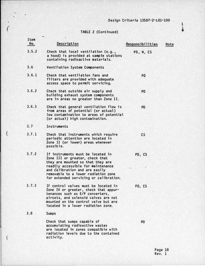
3. 5. 1 Check that sample stations for PO, N, CS routine samp l i ng of process fl uids are separated by shielding or di stance from other radioactive components to Zone I I .
a hood) i s provided at sa•ple stations contai ning radioactive •aterials.
PO, N. CS
3 . 6 Ventilation Syste. Components
3. 6. 1 Check that ventilation fans and ·po filters are provided with adequate access space to permit servicing.
3 . 6 . 2 Check that outside a f r supply and PO building exhaust system components are i n areas no greater than Zone I I .
3 .6 . 3 Check that general ventilation flow i s PO from areas of potential (or actual ) low contamination to areas of potential (or actual ) high conta.ination.
3 . 7 Instruments
( 3 . 7 . 1 Check that i nstruments which require cs periodic attention are located i n Zone I I (or lower) areas whenever possible.
3 . 7 . 2 If instruments must be located i n PD . CS Zone I I I or greater, check that they are mounted so that they are readily accessible for eai ntenance and calibratio" and are easily removable to a lower radiation zone for extended servicing or calibration.
3 . 7. 3 If control valves 11ust be located i n PO, CS Zone IV or greater. check that appur-tenances such as E/P converters, a f rsets. and solenoid valves are not mounted on the control valve but are located in a lower radiation zone.
3 . 8 Sumps
Check that sumps capabl e of accumulating radioactive wastes are located in zones compatible with radiation leve l s due to the contained
1. 1 Check that shielding or separation H i s provided between radiation zone areas to eeet the radiation level criteria for adjacent areas.
1 . 2 Check that shielding design i s based on conservative or measured radiation
H
source term, component design, and plant l ayout assumptions.
1 . 3 Check that poured concrete de�s i ty H, C specifications are consistent with shielding design basis •inimum dens ities.
1 . 4 Check that concrete block densi ty H, A
( speci fications are consistent with shielding design basis minimum densities.
1. 5 Check that concrete block wal l designs H, A meet or exceed the minimum shielding requirements.
1 . 6 Check that removable o r temporary N shielding f s desivned consistent w i th applicable radiation shtelding criteria for adjacent areas.
2. 0 Penetration and Di scontinuit� Shielding
2.1 Check that penetrations , such as H&V ducts and piping, are e i ther located with an offset between radiation sources
H, PO, E, CS
and accessible areas or are appropriately shielded.
2.2 Check that penetrations are located as N, PO, E , CS far as possible above the accessible floor elevation.
2.3 Check that penetration shielding i s provi ded as necessary to meet the
N
radiat ion shielding criteria i n adjacent accessible areas.
Page 19 Rev. 1
Ite11 No.
2 . 4
3 . 0
3. 1
3 . 2
Sec. C
1 . 0
1 . 1
I .
1 . 2
1 . 3
1 . 4
1. 5
Design Criteria 13587-Z-LOl-100
TABLE 2 (Continued}
Description
Check that seis•ic gap shielding i s provided to •aintain radiation levels i n adjacent accessible areas within radiation shielding criteria l i•its.
Ent�a� Shielding
Check that there i s no di rect or near di rect shine out of shielded cel l s .
Check that adequately shiel ded labyrinths or hatches are provided to l i•it di rect and scattered radiation out of shiel ded areas.
SYSTEM DESIGN
Decontamination Provisions
Check that radioactive syste•s with Zone V component radiation levels have provisions to flush the entire system. Fl ushing capabil i ty should be avai lable even i f the system pump i s i noperable.
Check that major components of the primary coolant purification system where crud can col lect up to Zone V radiation leve l s , such as fi l ters, heat exchangers , etc. have provi sions . for chemical decontamination, including low point drains. Check that •eans are available to take the decon solution to chemical waste area.
Check that seal flush water is provided to pumps with chemical or sl urry wastes.
Check that a l l serviceable components have isolating and draining capabi l i ty.
Check that prov i s i ons are available to flush potential ly contaminated instrument l i nes.
Res pons ibi l i ti es Note
N, C
N
N
H , PD
H , PO
H, PO
H , PO, CS
H, PO, CS
Page 20 Rev. 1
II
II
1 �
( J te11 .1!2:. 1 . 6
1. 7
1 . 8
2 . 0
2. 1
2 . 2
2. 3
3 . 0
3. 1
3 . 2
3. 3
Design Criteria 13587-2-LOl-100
TABLE 2 (Conti nued}
Description
Check that flush connections are l ocated dawnstrea. of the component isolation valve on the inlet l ine and upstream of the i solation valve on the outlet l i ne. and as close as possible to the inlet and outlet connections of the col!lponent.
Check that i solation valves are provided on the flush connections and are l ocated as close as possible to the aain pipe.
Check that a l l flush connections are equipped with quick connect/disconnect fittings.
Remote Operation and Instrumentation
Check that adequate process i nstrumen-tation and controls are ava i l able to al low system and component operation from a low radiation zone.
Check that f i l ters which accumulate high radioacti �ity are designed with the means ei ther to backflush the f i l ter remotely or to perform cartridge replacement with semi-remote tool s.
' Check that probe type i nstruients are used on highly radioactive tanks con-taining two-phase materi a l s .
leakage Provis ions
Check that tank overflow l i nes are di rected to the waste col lection system.
Check that sl udge tanks and a i r mixing tanks which contai n radioactive materials are vented to the respective building venti lation system or the vent col lection system.
Check that strainers are incl uded i n vent l i nes from tanks conta ining spent resins or sl udge.
Responsib i l i ties Note
H . PO
H . PO
H , PO
cs
PO
cs·
PO
PO
PO
Page 21 Rev. 1
Design Criteria 13587-2-L01-100 1
( I TABLE 2 (Conti nued) •
I tell � Description Responsibil ities Note
4 . 0 Demineral i zers
4 . 1 Check that deminera l i zers i n radio- PO active systems and associated piping are designed with provisions for being fl ushed with deminera l i zed water.
4 . 2 Check that strainers are l ocated inmed- PO iately downstream of ion exchangers .
4 . 3 Check that drains and do�nstream M, PO strainers are desi gned for ful l sys-tem pressure drop.
4 . 4 Check that strainers are incl uded PO i n vent l i nes from the deminera l i zer vessel .
4 . 5 Check that flush connections are PO
( provided at a l l critical locations (such as elbows, ties, valves) to clear potential plugs.
4 . 6 Check that flow i n piping i s turbulent enough to maintain suspension of fines.
H
5 . 0 Floor Drains
5. 1 Check that equipment drains are PO pipea directly to a drai nage col l ection system.
5 . 2 Check that prov isions are .ade to PO remove p l ugging should i t occur i n draf n 1 i nes.
5 . 3 Check that radioactive and potential ly PO radioactive drains are separated from nonradioactive drains.
lli.:...Q PIPING AND VALVE DESIGN
1 . 0 Pipe Routing
1 . 1 Check that piping containing radio- PO active materials is routed through sui tably zoned, control led access areas in accordance with p f ping
Page 22 Rev. 1
Design Criteria 13587-2-LOl-100 l
( TABLE 2 (Conti nued) � Item
Ho. Reseonsibi l i ties � radiation c l assi fication as shown i n Tabl e 3.
1 . 2 Check that equipment compartments PO conta in radioactive piping associated only with equipment within the compart-ment or that nonassocfated piping i s adequately separated.
1. 3 Check that where i t i s necessary PO, H for radioactive piping to be routed through corridors or other radiation zone areas , shielded pipeways are provided to meet area radiation l evel requi rements.
1 . 4 Check that long runs o f exposed PO radioactive piping are minimized, particularly i n active component areas such as valve gal leries or pump cel l s .
( 1. 5 Check that radioactive piping i s N, PO routed to take credit for shielding effects of equipment or structures.
2 . 0 Valve location
2. 1 Check that val ves are separated from components which accumulate or
N, PO
contain radioacti vity by shfelding or di stance to meet the applicable radiation shielding criteria leve l s .
2 . 2 Check that valves are readi ly accessi- PO, cs ble from fl oors or permanent platforms.
2. 3 Check that sufficient space i s pro- PO, cs vided to fac i l itate valve and valve operator mai ntenance, operations , and testing.
2 . 4 Check that valves are not located i n PO , cs radioactive pipeways .
2. 5 Check that vent and drain isolation PO, cs and instrument root isolation valves are located as close as practical to process piping or components.
Page 23 Rev. l
(
Item .1!2.:. 2. 6
2 . 7
3 . 0
3.1
3 . 2
( 3 . 3
3 . -l
3. 5
3 . 6
3. 7
3 . 8
Design Criteria 13587-Z-l01-100
TABLE 2 (Conti nued)
Responsi b i l i ties Note
Check that process valves are not l ocated at l ow points in piping.
PO
Check that reach rods or remote PO, N manipul ators are provided for manua l ly operated valves that are requi red i n potenti a l ly high radi-ation areas (Zone V or greater).
P ipe Des ign
Check that branch t i nes having l i ttle or no flow during nonaal operation
PO
are connected above the horizontal midpl ane of the mai n p i pe.
Check that thenaal expansion loops i n PO radioactive systems are rai sed rather than dropped.
Check that ori f i ces are located on PO, CS vertical piping runs i f possible. I f located i n horizontal piping runs, use eccentric design of the ori fice.
Check that reducers are i nstalled not PO to form a stagnant pocket, i . e. , usr. eccentric design with bottom flat, ,exc.ept at pumps •
. Check that ortfices l ocated i n hori-zontal runs use an eccentri c design only if suspended sol i ds are present i n the process f l uid.
Check that lengths of radioactive pipe runs and number of bends are •fnimized.
Check that l ow poi nts and dead legs i n radioactive p i p i ng are mini•ized and are capable of bei ng fl ushed.
Check that i nstrument and sens ing t i ne connections are located in such a way as to avoid corros ion product and radioactive gas bui ldup.
PO , CS
PO
PO
PO, CS
Page 24 Rev. 2
2
( Itu � 3 . 9
4 . 0
4 . 1
4. 2
( 4. 3
4 . 4
4 . 5
4 . 6
4. 7
Oesfgn Crfterfa 13587-2-l01-100
TABLE 2 (Continued)
Check that welded joints are used when-ever possible to •fni•fze crud traps f n the aechanfcal joints.
Valve and Valve Oeerator Selection
Check that ful l ported valves are used f n systeas expected to handle spent resins or sl urries with radiation levels of 25 mr/hr or greater at con· tact with the surface of the pipe. (See Table 3)
Check that valves 2-� i nches and l arger (except butterfly val ves and p l ug valves) in l i nes carrying radioactive fluids with radiation levels of 25 •rlhr or greater (con· tact dose rate) are di aphraga, pack-less, or have a double set of packing with lantern ring.
Check that a l l globe val ves in drain l i nes (excluding instrument valves) 2 i nches and smal ler are Y·pattern globe valves to faci l i tate rodding i f pl ugging should occur.
Check that remote operators or handwheel s on reach rods are provided for a l l valves, which aus( be accessible during operation, i n l i nes proc@�s i ng evaporator bottoms or spent res ins.
Check that pressure rel i ef 'lalves have flange connections to faci l i tate removal for set pressure verification and calibration.
Check that valve operators are properly selected and meet the criteria in Table 3.
Check that va lve types are properly sel ected for their intended ser-vice and envi ronment.
Reseonsibi l i ties Note
PO, CS
M, PO, CS
H, PO, CS
M, PO
H, PO, CS
M, PO
H, PO
H , PO
Page 25 Rev. 1
1 +
Design Criteria 13587-2-l01-100 1
( TABLE 2 (Continued) � I tem
No. Respons ibi l i ties Note
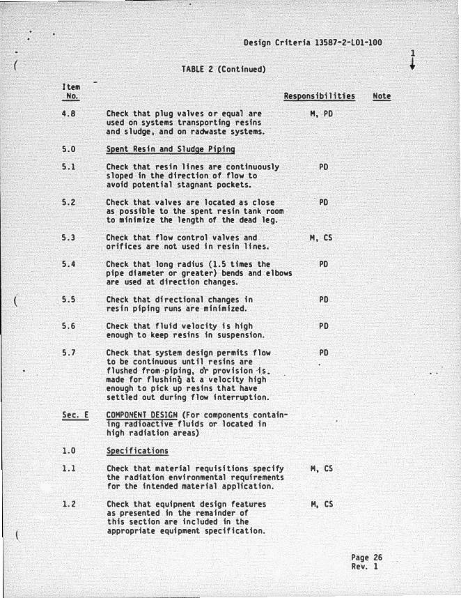
4 . 8 Check that plug valves o r equal are H, PO used on systems transporting resins and s l udge , and on radwaste systems.
5 . 0 Spent Res i n and Sludge Pipi ng
5 . 1 Check that res i n l i nes are continuously sloped in the direction of flow to
PO
avoid potential stagnant pockets.
5 . 2 Check that valves are l ocated a s close PO as possible to the spent resin tank room to minimize the l ength of the dead leg.
5 . 3 Check that flow control valves and H , CS orifices are not used i n resin l i nes.
5 . 4 Check that long radius { 1 . 5 times the pipe di ameter or greater) bends and el bows
PO
are used at direction changes.
( 5 . 5 Check that di rectional changes i n res i n piping runs are minimized.
PO
5 . 6 Check that fluid velocity i s high PO enough to keep resins in suspension.
5 . 7 Check that system design permits flow to be continuous unt i l resins are
PO
fl ushed from ·piping, o'r provision ·i.s . made for flushin� at a velocity high enough to pick up resins that have settled out during flow i nterruption.
Sec. E COMPONENT DESIGN (For components contain-ing radioactive fluids or l ocated i n high radiation areas)
1 . 0 Speci fications
1 . 1 Check that material requisi tions specify H, CS the radiation envi ronmental requi rements for the intended material application.
1 . 2 Check that equipment design features as presented in the remainder of
H, CS
this section are included in the appropriate equi pment specification.
Page 26 Rev. 1
Design Criteria 13587-2-l01-100 1
( ,
+ TABLE 2 (Continued}
Ite11 � Responsibi l i ties Note
2.0 Heat Exchangers
2. 1 Check that corrosion-resi stant tubes of stainless steel or other suitable
H
11aterial with welded tube-to-tube sheet joints are provided to minimize leakage.
2 . 2 Check that impact baffles are provided H with tube side and she l l side velocities l imited to minimize erosive effects.
2. 3 Check that drains are provided on the H, PO l owest portion to ensure removal of contaminated fluids.
2 . 4 Check that where practical the contam- H f nated side of the heat exchanger operates at a lower pressure than the clean side.
2 . 5 Check that the more radioactive stream H f s on the tube side.
( 3 . 0 Evaporators
Check that chemical addition connec- H tfons are provided to al low use of chemicals for descal ing operations.
4 . 0 Pumps (Sma l l)
•4. 1 Check that �ump ca�ings are provided H with drain connections.
4 . 2 Check that pumps i n radiation areas H (Zone I I I or higher} are purchased with mechanical seals to reduce seal servicing time and leakage.
4 . 3 Check that pumps i n radioactive H systems are prov i ded wfth fl anged connections for ease in removal .
4 . 4 Check that electrical quick di sconnects H , E are provided on pumps i n high radiation zones (V or higher).
4 . 5 Check that painted surfaces of the H , A pump ( i f any} are pai nted with a radiation-resistant and decontami nable coating.
Page 27 Rev. 1
(
Design Criteria 13587-2-lOl-100
Item � 4 . 6
4 . 7
TABLE 2 (Continued)
Check that the pump has long- l i ved bearings and that lubrication i s the permanent type.
Check that the pump selection has considered the use of low RPM designs.
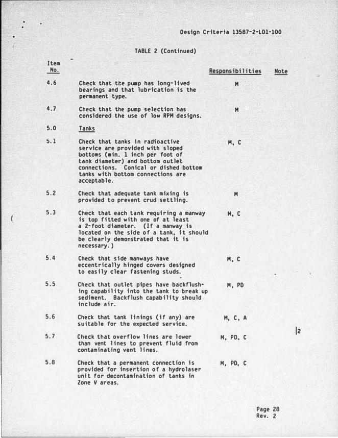
5.0 Tanks
!:i. l
5 . 2
5 . 3
5 . 4
5 . 5
5 .6
5 . 7
5 . 8
Check that tanks i n radi oactive service are provided with sloped bottoms (min. 1 inch per foot of tank diameter) and bottom outlet connections. Conical or di shed bottom tanks with bottom connections are acceptable .
Check that adequate tank mixing is provided to prevent crud settling.
Check that each tank requi ring a manway i s top fi tted with one of at least a 2- foot diameter. ( I f a manway i s located on the side o f a tank, i t should be clearly demonstrated that it i s necessary . )
Check that s i de manways have eccentrically hi nged covers designed to eas i ly clear fastening studs.
Check that outlet pipes have backflushing capabi l i ty i nto the tank to break up sediment. Backflush capab i l i ty should include a i r.
Check that tank l i nings ( i f any) are suitable for the expected service.
Check that overflow l i nes are l ower than vent l i nes to prevent fluid from contaminating vent l i nes.
Check that a permanent connection i s provided for insertion o f a hydrolaser uni t for decontamination of tanks in Zone V areas.
Responsibi l it i es
H
H
H, C
H
H, C
H , C
H , PO
H, C , A
H , PO, C
H , PO, C
Page 28 Rev. 2
lz
•
I tem � 5 . 9
5. 10
5. 11
5 . 12
5. 13
5. 14
6 . 0
6. 1
6. 2
6. 3
Design Criteria 13587-2-LOl-100
TABLE 2 (Continued)
Check that lap joints were not used i n tank construction.
Check that no backing strips were used on tank welds.
Check that backing rings were not used on nozzle welds.
Check that s iphoning of l i quid waste from tanks cannot occur.
Check that i n- l i ne f i l ters wfth backflushing cap�b i l ity are provided for tanks with a s l udge bui l dup potentia l .
Check to ensure that tanks with a potentially hazardous l eakage conse-quence are l ocated over catch pans or within curbs with drain l i nes leading to radioactive l i quid waste storage tanks or to sumps capable of handl ing a potential spi l l .
Instruments
Check that chemical seals are provided on sensing l i nes on process piping that may contain high amounts of sol ids.
Check that primary instruments which, for functional reasons , are l ocated in high radiation zones (V and greater) are designed for easy removal to a radiation Zone I I or l ower for cal i bra-tfon.
Check that instruments are sel ected which conta in minimal quanti ties of contaminated working fluids; e . g. , pressure transducers rather than be l l ows-type pressure gauges.
Res2onsibi l i ties Note
H, c
H , c
H, c
PO
PO
H , PO
cs
cs
cs
Page 29 Rev. 1
1 �
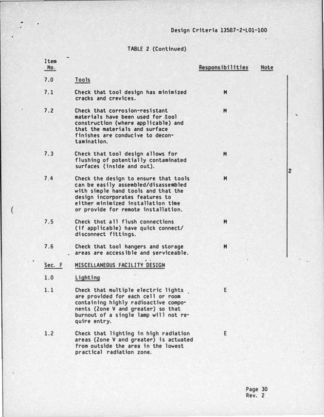
I tem � 7.0
7. 1
7 . 2
7. 3
7 . 4
( 7 . 5
7 .6
Sec. F
1 . 0
1. 1
1 . 2
Design Criteria 13587-2-L01-100
TABLE 2 (Continued)
Tools
Check that tool design has minimi zed cracks and crevices.
Check that corrosion-res i stant material s have been used for tool construction (where app l i cable) and that the materi a l s and surface fini shes are conduci ve to decon-lamination.
Check that tool design a l l ows for fl ushing of potential ly contaminated surfaces ( i nside and out).
Check the design to ensure that tools can be eas i ly assembled/di sassembled with simple hand tools and that the design i ncorporates features to ei ther minimized installation time or provide for remote installation.
Check that a l l f lush connections ( i f appl icable) have quick connect/ di sconnect fittings.
Check that tool hangers and storage areas are access ible and �erviceable .
MISCELLANEOUS FACILITY DESIGN
Lighting
Check that mul tiple electric l i ghts . are provided for each cel l or room containing highly radioactive compo-nents (Zone V and greater) so that burnout of a s i ngle lamp wi l l not re-quire entry.
Check that l i ghting i n high radiation areas (Zone V and greater) i s actuated from outside the area i n the l owest practical radiation zone.
Res�onsibi l i ties Note
H
H
H
H
H
H
E
E
Page 30 Rev. 2
2
Item No.
1 . 3
1. 4
1 . 5
1 . 6
( 2 . 0
2. 1
2 . 2
2 . 3
2 . 4
2 . 5
Design Criteria 13587-2-L01-100
TABLE 2 (Continued)
Check that sufficient l i ghting i s provided i n areas that conta in remote viewing devices to a l l ow their efficient use.
Check that plug- i n , accessible, bracket hung , removable units are provided for easy removal and relamping outside high radiation areas. (Lightweight units are preferable for ease of handl ing. )
Check that extension cord powered units stored on brackets and cord hangers outside the entrance are provided i f permanent units are not practical , and the pre-pl aced brackets are provided within the high radiation area to faci l itate insta l l ation.
Check that l ong-l i fe bulbs are provided in high radiation areas (Zone V).
Contamination Control and·Coatings
Check the floor drains and properly sloped fl oors are provided for each room or cubic l e conta ining sP.rviceable components with radiation lev�ls of a Zone I I I or higher.
Check that local gas traps or porous seals are not used on floor drains from radiation areas.
Check that gas traps are provided at the common sump or col l ection tank.
Check that concrete surfaces i n areas o f potential contamination are covered with a smooth-surfaced coating for the floor and wainscot, which wi l l a l l ow easy decontami nation.
Check that threshold curbs , cofferdams , or other means are provided to control radioactive l eakage or spi l l s .
Res2onsi bi l i ti es Note
E
E
E
E
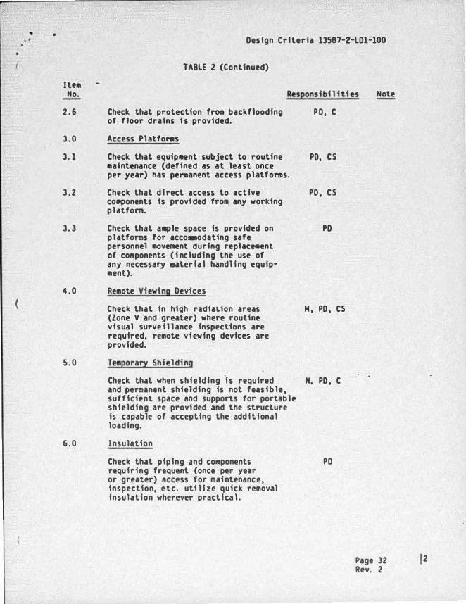
H , PO, C
H , PO
H, PO
N, A
PO, A , c
Page 31 Rev. 2 12
• . '
Itt• Ho.
2 . 6
3 . 0
3. 1
3 . 2
3. 3
4 . 0
(
5 . 0
6 . 0
Design Criteria 13587-2-LOl-100
TABLE 2 (Continued)
Responsi bi l i ti es Note
Check that protection fra. backflooding of floor drains i s provided.
Access Pl atfonas
Check that equipMent subject to routine •aintenance (defined as at least once per year) has penaanent access pl atforms.
Check that di rect access to active co.ponents is provi ded from any working pl attom.
Check that ample space is provided on pl atforms for accom.odating safe personnel •ovement during replace.ent of components ( i ncluding the use of any necessa� •aterial handl i ng equip· •ent).
Remote Viewing Devices
Check that in high radiation areas (Zone V and greater) where routine visual surve i l l ance inspections are required, remote viewing devices are provided.
TemporarY Shielding
Check that when shielding f s required and permanent shielding is not feasible, sufficient space and supports for portable shielding are provided and the structure is capable of accepting the additional loading.
Insulation
Check that piping and components requiring frequent (once per year or greater) access for mai ntenance, inspection, etc. uti l i z e quick removal insulation wherever practica l .
PO, C
PO, CS
PO , CS
PO
H , PO , CS
H, PO , C
PO
Page 32 12 Rev. 2
(
-• Design Criteria 13587-2-LOl-100
TARLE 2 (Continued)
Ite• .1!2.:. Responsi bi l i ti es
7.0 Plant Services
� PO
cs
A
E
c
H
N
*
Check that services such as e l ectrical power, �ater, respi rabl e a i r , and compressed a i r are available reasonably close to radiation work areas.
Legend
Descrfpt ion
Plant Design
Control Syste111s
Architectural
El ectrical
Ci v i l
Mechanical
Nuclear/Licensing
M, PO, E , H
I tem to be completed prfor to transmittal of general arrangement drawing to c l i ent for initial review.
Page 33 j z Rev. 2
. ..
•
(
Design Criteria 13587-2-LOl-100
TABLE 3
TYPICAL RADIOACTIVE PIPING CLASSIFICATION AND ROUTING
Exposure Rate at Acceptable Contact with Pipe Radioactiv i ty Radiation Zone
Surface {mR/hrl Descrietion Routing*
Nonradioactive I , I I , I I I , IV, V
0. 5 Sl ightly I • I I , I l l . IV, V radioactive
2 . 5 Low radioactivity I I , U l , IV, V
25 low to �oderately radioactive
II I , IV, V
100 Moderately radioactive
IV, V
>100 Highly radioactive V, VI , VII
* Routing of nonradioacti ve or low radioactivity piping in high radi ation zones should be m i nimized.
Page 34 I 2 Rev. 2
•
Zone
I S0.5" I I 0. 5 to 2. 5
I I I 2. 5 to 25
IV 25 to 100
v 100 to 1000
VI 1000 to 3000
V I I �3000
Design Criteria 13587·2·l01·100
TABLE 4
RADIATION ZONES
Access Description
Uncontrol led, unl imited access Control led, l imited access 40 hours per week Control led, l imited access 4 to 40 hours per week Control led, l imited access 1 to � hours per week Norma l ly i naccessible access during eme� gency Norma l ly i naccessible access during emer· gency Locked barrier to zone Normally i naccessible access during eme� gency Locked barrier to zone
" Design dose rates i n office spaces and other Zone I areas which are continuously occupied 8 hours per day, 5 days per week or more sha l l be less than 0.25 mrem/hr. Corridors and other Zone I areas of a trans ient occupancy nature sha l l be below 0. 5 mrem/hr.