IAEA-TECDOC-1503 Nuclear power plant life management processes: Guidelines and practices for heavy water reactors Report prepared within the framework of the Technical Working Groups on Advanced Technologies for Heavy Water Reactors and on Life Management of Nuclear Power Plants June 2006
Transcript
IAEA-TECDOC-1503
Nuclear power plant lifemanagement processes:
Guidelines and practices forheavy water reactors
Report prepared within the framework of the Technical Working Groupson Advanced Technologies for Heavy Water Reactors and on
Life Management of Nuclear Power Plants
June 2006
IAEA-TECDOC-1503
Nuclear power plant lifemanagement processes:
Guidelines and practices forheavy water reactors
Report prepared within the framework of the Technical Working Groupson Advanced Technologies for Heavy Water Reactors and on
Life Management of Nuclear Power Plants
June 2006
The originating Section of this publication in the IAEA was:
Nuclear Power Engineering Section International Atomic Energy Agency
Wagramer Strasse 5 P.O. Box 100
A-1400 Vienna, Austria
NUCLEAR POWER PLANT LIFE MANAGEMENT PROCESSES: GUIDELINES AND PRACTICES FOR HEAVY WATER REACTORS
IAEA, VIENNA, 2006 IAEA-TECDOC-1503 ISBN 92–0–106206–0
The time is right to address nuclear power plant life management and ageing management issues in terms of processes and refurbishments for long term operation and license renewal aspects of heavy water reactors (HWRs) because some HWRs are close to the design life. In general, HWR nuclear power plant (NPP) owners would like to keep their NPPs in service as long as they can be operated safely and economically. This involves the consideration of a number of factors, such as the material condition of the plant, comparison with current safety standards, the socio-political climate and asset management/ business planning considerations.
This TECDOC deals with organizational and managerial means to implement effective plan life management (PLiM) into existing plant in operating HWR NPPs. This TECDOC discusses the current trend of PLiM observed in NPPs to date and an overview of PLiM programmes and considerations. This includes key objectives of such programs, regulatory considerations, an overall integrated approach, organizational and technology infrastructure considerations, importance of effective plant data management and finally, human issues related to ageing and finally integration of PLiM with economic planning. Also general approach to HWR PLiM, including the key PLiM processes, life assessment for critical structures and components, conditions assessment of structures and components and obsolescence is mentioned. Technical aspects are described on component specific technology considerations for condition assessment, example of a proactive ageing management programme, and Ontario power generation experiences in appendices. Also country reports from Argentina, Canada, India, the Republic of Korea and Romania are attached in the annex to share practices and experiences to PLiM programme. This TECDOC is primarily addressed to both the management (decision makers) and technical staff (engineers and scientists) of NPP owners/operators and technical support organizations, and will be also of interest to NPP regulators and designers. It is intended to be a living publication and will be periodically updated and supplemented as new knowledge is gained. The guidance provided is applicable also to future HWR NPPs. This TECDOC has been prepared by a group of experts from five Member States namely: Argentina, Canada, India, the Republic of Korea and Romania. The work of all contributors to the drafting and final review of this report, identified at the end of this TECDOC, is greatly appreciated.
In particular, the IAEA acknowledges the contributions of, R. Versaci (Argentina), A. Blahoianu and C. Moses (Canada), S.A. Bhardwaj (India), Kyung Soo Lee, Ill Seok Jeong (Republic of Korea) and P. Barbulescu (Romania). Special thanks are due to F. Nuzzo (Canada) and J. Nickerson (Canada), who also chaired the technical meetings. The IAEA officers responsible for this publication were Ki-Sig Kang and J. Cleveland of the Division of Nuclear Power.
EDITORIAL NOTE
The use of particular designations of countries or territories does not imply any judgement by the publisher, the IAEA, as to the legal status of such countries or territories, of their authorities and institutions or of the delimitation of their boundaries.
The mention of names of specific companies or products (whether or not indicated as registered) does not imply any intention to infringe proprietary rights, nor should it be construed as an endorsement or recommendation on the part of the IAEA.
CONTENTS
1. INTRODUCTION ............................................................................................................ 1 1.1. Background......................................................................................................... 1 1.2. Definition of terminology................................................................................... 2 1.3. Scope and objective ............................................................................................ 2 1.4. Other related IAEA publications ........................................................................ 3 1.5. Structure.............................................................................................................. 5
2. PLANT LIFE MANAGEMENT OVERVIEW................................................................ 7
2.1. Objectives ........................................................................................................... 7 2.2. Provisions for plant life management ................................................................. 8 2.3. Approaches to plant life management ................................................................ 9
2.3.1. Introduction of approaches for PLiM....................................................... 9 2.3.2. License renewal application ..................................................................... 9 2.3.3. Periodic safety review application.......................................................... 10 2.3.4. Combined approach with PSR and LRA................................................ 12
2.4. Regulatory aspect and considerations............................................................... 13 2.4.1. Regulatory approach in Canada.............................................................. 14 2.4.2. Regulatory approach in the Republic of Korea ...................................... 16 2.4.3. Regulatory approach in India ................................................................. 16
2.5. Overall integrated approach.............................................................................. 18 2.6. Plant organization considerations ..................................................................... 21 2.7. Technology infrastructure................................................................................. 22 2.8. Supporting data management ........................................................................... 23 2.9. Human issues related with human ageing management ................................... 23
2.9.1. Availability of qualified NPP personnel................................................. 23 2.9.2. Training and re-training — Knowledge management............................ 24 2.9.3. Personnel exposure to radiation ............................................................. 24
2.10. Integration with economic planning ................................................................. 24 3. GENERAL APPROACH TO HWR PLIM .................................................................... 26
3.1. Screening SSCs................................................................................................. 26 3.2. Life assessments for critical structures and components.................................. 27 3.3. Condition assessment of structures and components and commodities ........... 28 3.4. Critical system assessments.............................................................................. 29
3.4.1. Condition assessment of systems ........................................................... 29 3.4.2. Systematic maintenance planning (SMIP) assessments ......................... 30 3.4.3. Alternative approach to systematic maintenance planning: The
3.8.1. Overview of integrated safety performance assessments....................... 34 3.9. Plant life management implementation ............................................................ 35 3.10. Long term operation planning .......................................................................... 36 3.11. Regulatory considerations for long term operation .......................................... 37
3.11.1 Overview of the Canadian regulatory position on long term operation ............................................................................... 38
3.11.2. Overview of the Korean regulatory position on long term operation ............................................................................... 39
3.12. PLiM and power uprate .................................................................................... 39 4. CONCLUSIONS AND RECOMMENDATIONS ......................................................... 41
APPENDIX II.: EXAMPLE OF A PROACTIVE AGEING MANAGEMENT PROGRAMME ................................................................ 69
APPENDIX III.: OPG EXPERIENCES — COMMON SYSTEMS FOR MULTI UNITS.... 75 ANNEX I: INDIA .................................................................................................................... 87 ANNEX II: REPUBLIC OF KOREA...................................................................................... 99 ANNEX III: ROMANIA....................................................................................................... 107 ANNEX IV: CANADA ......................................................................................................... 113 ANNEX V: ARGENTINA..................................................................................................... 117 CONTRIBUTORS TO DRAFTING AND REVIEW ........................................................... 123
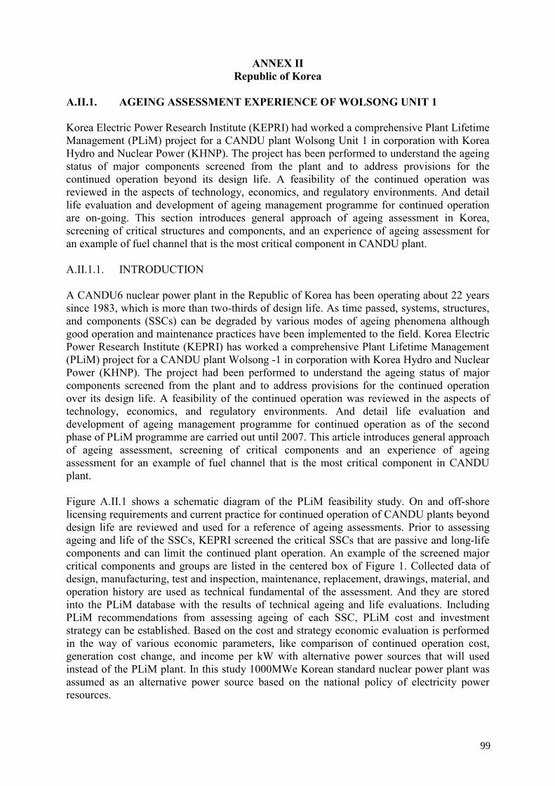
1. INTRODUCTION 1.1. BACKGROUND The design life of a nuclear power plant (NPP) does not necessarily equate with the physical or technological end-of-life (EOL) in terms of its ability to fulfill safety and electricity production requirements. Operating equipment, generically called systems, structures and components (SSCs) in a NPP is subjected to a variety of chemical, mechanical and physical conditions during operation. Such stressors lead to changes with time in the SSC material properties, which are caused and driven by the effects of corrosion, varying loads, flow conditions, temperature and neutron irradiation, for example. Even allowing for significant ageing effects in SSCs, it is quite feasible that many NPPs will be able to operate for times in excess of their nominal design lives, provided appropriate and proven ageing management measures are implemented in a timely manner. This aspect has been recognized by operators and regulators alike, as seen in the number of license renewal applications and approvals, respectively, in the USA, and, elsewhere, by extending licensing procedures, primarily based on periodic evaluation of safety, i.e. periodic safety reviews (PSR). In general, heavy water reactor (HWR) NPP owners would like to keep their NPPs in service as long as they can be operated safely and economically. Their decisions depend upon the business model. They involve the consideration of a number of factors, such as the material condition of the plant, comparison with current safety standards, the socio-political climate and asset management/ business planning considerations. Historically, most NPP owners (including owners of HWRs) felt that their routine maintenance, surveillance and inspection programmes would be adequate in dealing with the ageing processes that would occur at their plants. However, starting in the early 1990s and following, it has become widely recognized that a more systematic and comprehensive approach generally known as integrated plant life management (PLiM) or life cycle management (LCM) is needed. Fig. 1 shows the number of HWR reactors by age. 18 reactors have been operated more than 20 years and 5 reactors have been operated more than 30 years.
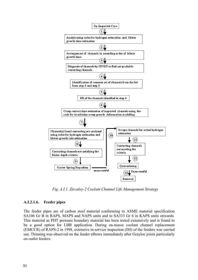
Fig. 1. Number of HWR reactors by age as of October 2005.
No. of Unit
1
1.2. DEFINITION OF TERMINOLOGY The following IAEA terminology and definitions have been adopted throughout the TECDOC: • Ageing is defined as the continuous time dependent degradation of SSC-materials due to
normal service conditions, which include normal operation and transient conditions; postulated accident and post-accident conditions are excluded. It is emphasized here that ageing is a wide term, and may even be extended to include the extent and current level of personnel training and even the status of updated documentation used in the NPP.
• Ageing management (AM) is defined as engineering, operations and maintenance actions to control within acceptable limits ageing degradation of systems, structures and components (SSCs).
• Ageing management programme (AMP) is defined as any programme or activity that adequately manages the effect of ageing on SSCs (e.g. maintenance programme, chemistry programme, inspection or surveillance activities, etc.).
• Condition assessment (CA) is defined as an ageing assessment methodology applied to systems, as well as components and structures, or groups of components with similar characteristics (commodities).
• Life assessment (LA) is defined as an ageing assessment methodology applied to critical and/or complex components and structures that involve mainly passive functions and typically are not expected to be replaced within the original design life of the plant.
• Plant life management (PLiM) is the integration of ageing and economic planning to: • Maintain a high level of safety • Optimize the operation, maintenance and service life of SSCs; • Maintain an acceptable level of performance; • Maximize return on investment over the service life of the NPP; and • Provide NPP utilities/owners with the optimum pre-conditions for long term
operation (LTO).
• LTO of an NPP so long as all safety requirements are fulfilled and that economic viability, taking into account all costs, including PLiM measures is guaranteed. LTO is a utility/owner policy of intent to operate beyond the original design life.
Therefore, PLiM for NPPs is a methodology whereby all expenses are optimized to favour commercial profitability and competitiveness, while providing safe and reliable supplies of electrical power. In general, PLiM may be defined as the continuous operation of the plant, with an acceptable level of safety, beyond a licensing period established following a safety assessment. 1.3. SCOPE AND OBJECTIVE This TECDOC deals with organizational and managerial means to implement effective PLiM into existing plant in operating HWR NPPs. The guidance provided is applicable also to future HWR NPPs. The objective of a PLiM programme is to effectively integrate ageing management programmes and economic planning to maintain a high level of safety, optimize the operation, maintenance and service life of SSCs, maintain an acceptable level of performance, maximize return on
2
investment over the service life of the NPP; and provide NPP utilities/owners with the optimum pre-conditions for PLiM. This TECDOC is primarily addressed to both the management (decision makers) and technical staff (engineers and scientists) of NPP owners/operators and technical support organizations, and will be also of interest to NPP regulators and designers. It is intended to be a living publication to be periodically updated and supplemented as new knowledge is gained. The specific objective of the report is to assist HWR NPP owners/operators with PLiM programmes by providing guidance on: • Typical processes and methodologies in HWR PLiM programmes, including plant
organization considerations, technology infrastructure and supporting data management, • Component-specific technology considerations for several of the most important HWR
SSCs, • Planning for long term operation (refurbishment/life extension), • Strengthening the role of proactive ageing management, and • Implementing a systematic ageing management process.1 1.4. OTHER RELATED IAEA PUBLICATIONS The present report references a variety of other IAEA publications that have been developed in the IAEA project on Safety Aspects of NPP Ageing. Some of these deal exclusively with HWR components; others include HWR components in a report that also includes light water reactor (LWR) components. For background, the project and its main products, including the previously issued programmatic guidelines, are summarized in this section. The IAEA initiated information exchange on safety aspects of NPP ageing in 1985 to increase awareness of the emerging safety issue relating to physical ageing of plant SSCs. In 1989 a systematic project was begun aimed at assisting Member States in understanding ageing of SSCs important to safety and in effective ageing management of these SSCs in order to ensure their integrity and functional capability throughout their service life. This project integrated information on the evaluation and management of safety aspects of NPP ageing generated by Member States into a common knowledge base, derives guidance, and assists Member States in the application of this guidance. Main publications of the project [1–14, 20, 21] fall into five groups. Figure 2 shows the stature of IAEA publications related with ageing management and PLiM. Awareness Following the first International Conference on Safety Aspects of Ageing and Maintenance of Nuclear Power Plants [1] which was organized by the IAEA in 1987, increased awareness of physical ageing of SSCs and its potential safety impact was achieved by the development and wide dissemination in 1990 of IAEA-TECDOC-540 on Safety Aspect of Nuclear Power Plant Ageing [2]. In the 1980s most people believed that classical maintenance programmes were
1 Systematic ageing management process is the application of the Plan-Do-Check-Act cycle to operations,
maintenance, and engineering actions aimed at achieving effective ageing management, which is based on the understanding of ageing.
3
adequate for dealing with the ageing of NPPs. However, in the 1990s the need for ageing and life management of NPPs became widely recognized. Programmatic guidelines The following programmatic guidance reports have been developed using experience of Member States.
• Data Collection and Record Keeping for the Management of Nuclear Power Plant Ageing [3] provides information on the baseline, operating and maintenance data needed and a system for data collection and record keeping.
• Methodology for the Management of Ageing of Nuclear Power Plant Components Important to Safety [4] gives guidance on screening SSCs to make effective use of limited resources and on performing ageing management studies to identify or develop effective ageing management actions for the selected components.
• Implementation and Review of Nuclear Power Plant Ageing Management Programmes [5] provides information on the systematic ageing management process and an organizational model for its implementation.
• Equipment Qualification in Operational Nuclear Power Plants [6] provides the current methods and practices relating to upgrading and preserving equipment qualification in operational NPPs and reviewing the effectiveness of plant equipment qualification programmes.
Component specific guidelines
Based on current experience, practices in Member States and methodology for the management of ageing of NPP components important to safety [4], guidelines to assess and manage ageing of major NPP components important to safety have been developed through technical meetings and coordinated research projects (CRPs). Main objectives for each specific component guideline are:
• To identify significant ageing mechanisms, • To document the current practices for the assessment and management of ageing, • To assist Member States in establishing a systematic ageing management programme. The comprehensive technical guidelines have been issued with common contents as shown below [11–21].
• Component description • Component design basis • Potential ageing mechanisms • Inspection, monitoring and maintenance requirements, techniques and practices • Methods for the assessment of degradation • Methods for the mitigation of degradation • Systematic component specific ageing management programme (AMP) Ageing Management Review Guidelines [15] is a reference report for Ageing Management Assessment Teams (AMAT) and for utility self-assessments; these reviews can be programmatic or problem oriented. The focus of the project work has progressively shifted from developing awareness, to preparing programmatic, and then component specific guidelines. In
4
future, the focus will be on providing services to assist Member States in the application of the guidelines. A reduced effort will be maintained to facilitate information exchange through the preparation of additional guidelines and updating of existing guidelines. Safety Guide on Ageing Management is being developed for NPP and research reactor. This SG (DS-382) will provide guidelines for operators on how to improve the existing AMPs and implement the effective AMPs for new NPPs. Regulators will use it to set up requirements and verify NPP’s compliance with requirements.
Fig. 2. Structure of IAEA publications related with PLiM and ageing management.
1.5. STRUCTURE Section 1 introduces the background, definition of terminology and related IAEA publications and Section 2 discusses the current trend of PLiM observed in NPPs to date and an overview of PLiM programmes and considerations. This includes key objectives of such programmes, regulatory considerations, an overall integrated approach, organizational and technology infrastructure considerations, importance of effective plant data management and finally, human issues related to ageing, and finally integration of PLiM with economic planning. Section 3 discusses general approach to HWR PLiM, including the key PLiM processes, life assessment for critical structures and components, conditions assessment of structures and components and obsolesces. It also gives regulatory consideration both for design life and for
Programmatic Guidelines (5)
Component Specific Guidelines (13)
Ageing Management Review guideline (1)
DS 382
under developing
Safety Guide on Ageing Management under developing
Safety Guide on PSR
Safety of Nuclear Power Plant Design NS R-1
Safety of Nuclear Power Plant Operation NS R-2
Maintenance/I&C modernization (10)
Guidelines on activities for effective life management and integrity of Reactor Pressure Vessels (8)
Safety Guide on MSI
Safety Guide on Personal Qualification
Human Ageing Guideline (10)
5
long term operation. Section 4 presents conclusions and recommendations. In the appendices, technical aspects are described on component specific technology considerations for ageing assessment, example of a proactive ageing management programme, and Ontario Power Generation (OPG) experiences on common systems for multi units. In addition, country reports of Canada, India, the Republic of Korea, Romania and Argentina are attached as annexes.
6
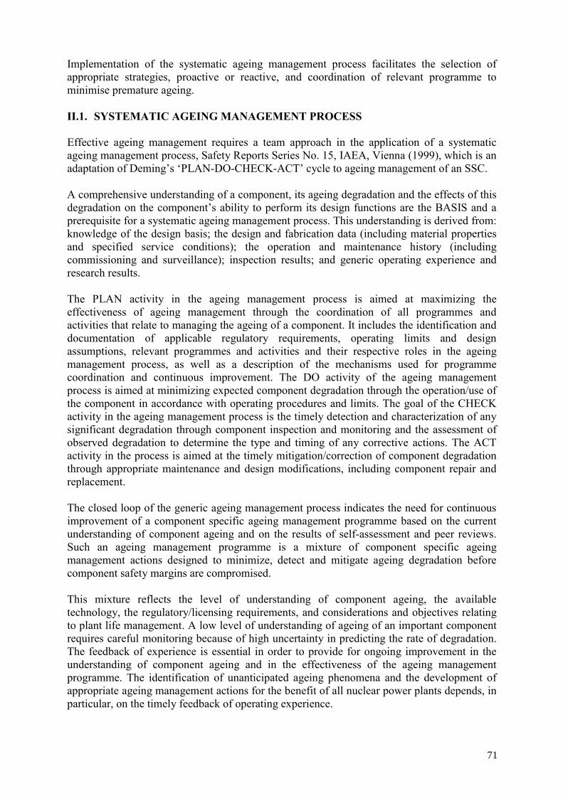
2. PLANT LIFE MANAGEMENT OVERVIEW Key attributes of an effective plant life management programme include a focus on important SSCs which are susceptible to ageing degradation, a balance of proactive and reactive ageing management programmes, and a team approach that ensures the coordination of and communication between all relevant NPP and external programmes. Continued plant operation, including operation beyond design life (usually called long term operation), depends, among other things, on the physical condition of the plant. This is influenced significantly by the effectiveness of management ageing process. Most HWR NPP owners/operators use a mix of maintenance, surveillance and inspection (MSI) programmes as the primary means of managing ageing. Often these programmes are experience-based and/or time-based and may not be optimized for detecting and/or managing ageing effects. From time-to-time, operational history has shown that this practice can be too reactive, as it leads to dealing with ageing effects (degradation of SSCs) after they have been detected. Reactive ageing management (i.e. repairing or replacing degraded components) may be cost effective for some, in particular, small replaceable components. However, for most important SSCs, utilizing proactive ageing management is generally most effective from both the safety and economic perspective. Premature ageing of NPP SSCs implies ageing degradation that occurs earlier than expected. It can be caused by pre-service and service conditions (fabrication, installation, commissioning, operation, or maintenance) that are more severe or different than assumed in the design. For instance, frequent pressure/ temperature transients, particularly those that have been not considered in the design basis, might lead to premature component fatigue. Even small changes, particularly those that affect the chemistry of the circuits, may induce premature degradation several months or years later. Excessive testing and/or routine maintenance can accelerate wear-out of components without additional benefit. Such conditions may not have been taken into account in the usual MSI programmes, unless there is a systematic and comprehensive assessment of ageing effects. In many cases premature and/or undetected ageing cannot be traced back to one specific cause or an explicit error. The root cause is often a lack of communication, documentation and/or coordination during design, fabrication, commissioning, operation or maintenance. This lack of effective communication and interfacing frequently arises because, with the exception of major SSCs, such as the fuel channels or steam generators, there is a lack of explicit responsibility for achievement of specific SSC lifetime. Lack of effective communication and coordination can be remedied by the implementation of a systematic ageing management process. 2.1. OBJECTIVES During the design of the original HWR stations, potential mechanisms for ageing of the plant were considered, and inspection and maintenance programmes were developed. These programmes were based on the best information available from the nuclear power industry at that time. Since then, the HWR industry have been using the experience gained through the operation of these reactors, and throughout the industry in general, to develop systematic and comprehensive PLiM programmes to assure the on-going safe and economic operation of the reactors.
7
As stated previously, the objective of a PLiM programme is to effectively integrate ageing management programmes and economic planning to maintain a high level of safety, optimize the operation, maintenance and service life of SSCs, maintain an acceptable level of performance, maximize return on investment over the service life of the NPP; and provide NPP utilities/owners with the optimum pre-conditions for PLiM. The following are typical specific objectives of a systematic PLiM programme for HWRs: • To perform a comprehensive assessment of the critical SSCs; • To develop or enhance the plant maintenance, surveillance/monitoring, inspection and
testing, and rehabilitation programmes to effectively manage the effects of ageing degradation;
• Strengthening the role of proactive ageing management; • Implementing a systematic ageing management process; • For in-service plants, ensure continuing safe, reliable, and cost effective operation
during the plant design life in accordance with the following goals: • Maintain public risk well within the regulatory requirements; • Maintain high lifetime capacity factors, contributing to providing electricity at a
competitive cost; • Be able to anticipate new and emerging ageing issues and therefore minimize
“unexpected” problems; and • Preserve the option for long term operation of NPP.
For new HWR plants, additional objectives may be to: • Assure plant owner/operators that HWR can meet and exceed its target design life; and • Provide an optimized cost effective maintenance programme (using ageing assessment
experience to provide this assurance). The starting point should be the definition of the desired operational life. The programmes and measures for ensuring the required safety and performance levels, also the investments needed, depend on the target time of operation. A reasonable time-target should be selected for the economic investments in order to achieve the profit expected. 2.2. PROVISIONS FOR PLANT LIFE MANAGEMENT NPP life is determined by a wide range of factors that include reactor type, material selection, design, operation and maintenance practices, regulatory and political environment, economics, etc. The original design life is generally 30 to 40 years. However, the actual service life may be less (or more) based on the wide range of factors. PLiM goal of optimizing safe operation with economical competitive operation is relevant no matter how long the plant operates. Introduction of PLiM as a method for managing the plant service life in a safe and economically optimized way has to consider the following provisions: • General condition of the plant; • Current practices for operation, maintenance, testing, surveillance and inspection; • Data records, reports and SSC’s life-history or capability to obtain & retain this
information (in the case of a young plant); and • Knowledge of design basis (number of load-cycles, material properties, etc.)
8
For PLiM, additional information should be considered, such as: • Safety issues, their ranking and scheduling of necessary measures; • Technical issues affecting the operational performance and costs; • Market conditions and the economic environment; • Political and regulatory environment, and • Economic targets. 2.3. APPROACHES TO PLANT LIFE MANAGEMENT 2.3.1. Introduction of approaches for PLiM There are two conceptual approaches that can be applied concerning a utilities’ plan for continued operation. One is based on periodic safety review (PSR) [24], another on license renewal application (LRA) [25]. The USA practice and regulations follow LRA concept, while most of the European countries and Japan use PSR for obtaining permission for continued operation and to support eventual arguments for long term operation. In some Member States, these two different concepts and regulatory approaches have been adapted (e.g. Spain, Hungary, and the Republic of Korea, see table 1). Table 1. Term of license of nuclear power plant
Limited Term of license Unlimited Term of license Canada (3–5 years) Belgium (10 years) Hungary (30 years) France (10 years) Finland (10–20 years) Germany(10 years) Republic of Korea (30, 40 years) Japan(10 years) United States of America (40 years) Sweden(8–10 years) United Kingdom (10 years) India (9 years) Argentina (30 years) Spain (10 years) Switzerland (10 years)
2.3.2. License renewal application License renewal (LR) in the USA is based on the pre-requisite that ageing management of active components and systems is adequately addressed by the maintenance rule (MR) [26] requirements (10 CFR Part 50.65) and other established regulatory processes. This assumption is validated by the nuclear regulatory commission (NRC)’s regulatory oversight of the current licensing basis (CLB), which includes regulatory oversight to ensure implementation of continuous performance monitoring of active system functions in accordance with the MR, on-going compliance with operation technical specifications and regular updating of the so-called final safety analysis report (FSAR). LR provides NPPs with the regulatory option to continue to operate beyond the 40-year term of the original licence, whilst the final decision to continue operation will depend on economic analyses of individual NPPs. Obviously, if the plant becomes uneconomical to operate, it may be shutdown and decommissioned at any time. LR focuses primarily on the following three areas:
9
• Integrated plant assessment to evaluate the AM of passive, long lived SSCs, to ensure that they can support continued safe plant operation beyond the 40-year term of the original operating license and remain within the safety evaluation and requirements;
• Assessment of time-limited ageing analyses (TLAA) (e.g. fatigue, neutron embrittlement, environmental qualification analysis) to address the additional twenty years of operation; and
• Environmental impact assessment of the additional twenty years of operation.
The primary bases for determining the adequacy of passive SSC ageing management are operating experience, research results, and material sciences. Considerable documentation of operating experience is available in published reports, such as NRC regulatory guides, generic ageing lessons learned reports (e.g. NUREG-1801, [27]), and industry reports (e.g. NEI 95-10, [28]). NPPs must have at least 20 years of operating experience to demonstrate the adequacy of existing AMPs prior to submitting an application for LR. The LR process typically takes about 4 to 5 years to complete. The utility takes about 2 years to do the engineering and environmental assessment work needed to prepare an application, and the NRC takes about 22 months (range of 17 to 30 months based on experience so far) to review the application and prepare a safety evaluation report (SER) and environmental impact statement. The overall cost of the LR process is $10 to $20 million (including utility costs and regulatory review fees) over this 4 to 5 year period. Fig.3 shows the review process of LR application.
ACRS: Advisory Committee on Reactor Safeguards
Fig. 3. Review process of licensing renewal application.
2.3.3. Periodic safety review application In many countries, the safety performance of the NPPs is periodically followed and characterized via the periodic safety review (PSR) approach [24]. The regulatory review and acceptance of the PSR gives the licensee the permission to operate the plant for up to the end
Review inAccordancewith Part 54
Review inAccordancewith Part 51
LicenseRenewal
Application
ScopingActivities
DraftSupplement
to GEIS
Commentson Draft
FinalSupplement
to GEIS
InspectionActivities
SafetyReview
ACRSReview
SafetyEvaluation
Report
NRC Decisionon Application
ACRSLetter
Letter onInspectionActivities
Hearings*
Formal PublicParticipation
* If a request for hearing is granted
Safety
Environmental
10
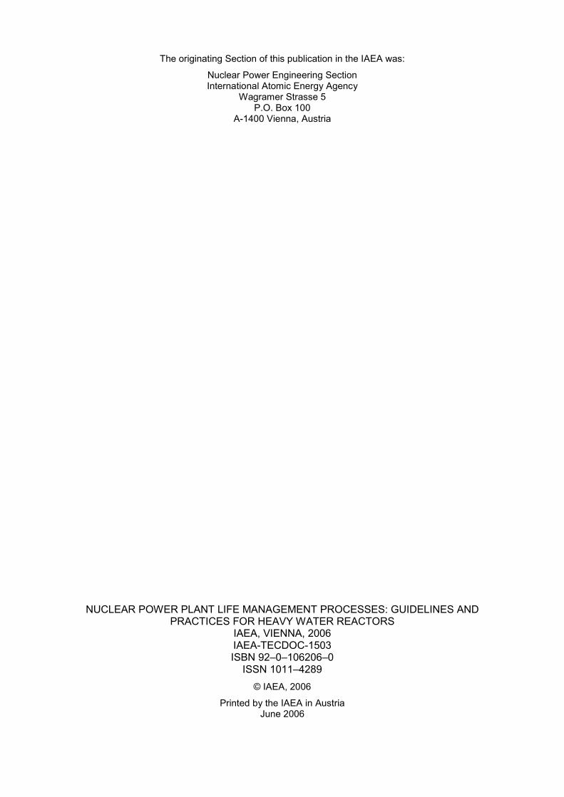
of the next PSR cycle (usually 10 years). The regulatory system does not limit the number of PSR cycles, even if the new cycle is going beyond the original design lifetime of the plant. The only condition is to demonstrate the safety of the plant operation for the next PSR cycle while maintaining safety and operational margins. The PSR is a tool that may be used by regulators for the identification and resolution of safety issues in NPPs. In this framework, continued operation may be strived for by applying the results of the PSR, by identification and resolution of the safety issues as a condition of operation for the new PSR cycle. The PSR is not an adequate tool to control changes and tendencies with an evolution time shorter than 10 years. It is also not a suitable system in case the licensee needs a technological guarantee for a long term operation longer than 10 years; in many cases economical considerations suggest an extension of 20 years, or more, of the original design life. Figure 4 shows the flowchart of an overall process for periodic safety review of NPP. However, it must be noted here that the concept of PSR was developed to be part of the normal regulatory or safety monitoring process, and not specifically to justify beyond design life operation of a plant. The PSR was originally used primarily to assess the safety status of the plants designed to early standards. In these cases, the PSR gives an overall review of all aspects of plant operation that may be relevant to safety. This review includes subjects such as emergency arrangements, organization and administration, procedures, research findings and feedback of experience. All of them are mainly relevant to current operation, and not directly related to the justification for continued operation. A PSR implemented beyond the original NPP’s design life may require a deeper safety review, addressing the following:
• Evaluation of the plant safety against current standards; • A new evaluation and/or qualification for items affected by time-dependent phenomena; • The AMP, which has to be extended over the extended operating life; and • A new safety assessment, to show that the as-designed conservatism (not the safety
margin) may be reduced, based on improved plant operation practices and better understanding of the degradation mechanisms. The overall safety margin must be kept consistent with current safety requirements.
In conclusion, a full scope PSR applied with a view beyond design life operation is fully not different in principle than a usual PSR applied during the design life at ten-yearly intervals, but the emphasis has to be oriented to the ageing of SSCs limiting the total plant operational life and always on the related safety issues. Table 2 shows the list of PSR implementation in Member States.
11
Agreement between
owner/operator and regulator on general scope and requirements
for PSR and its expected outcome
Preparation of the PSR project
PSR reviews
Preparation of the programmeof corrective actions
Steps
of
review
procedure
Starting point of
PSR
End point of
PSR
Activities of the
regulator
Approval of an integrated programme of
corrective actions
Fig. 4. Flowchart of an overall process for periodic safety review of NPP. Table 2. List of MS of PSR implementation
Status of PSR Implementation Member States (MS)
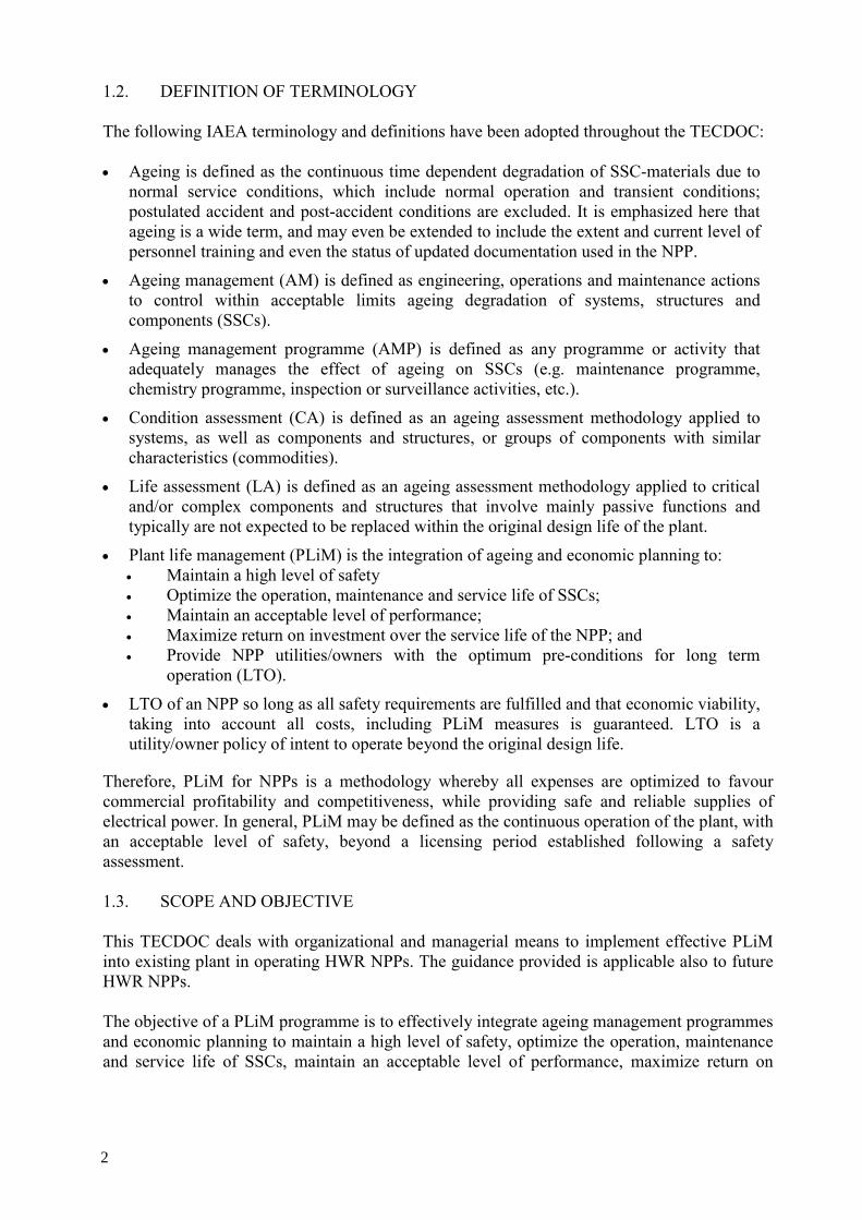
PSRs have been completed in MS Belgium, China (Qinshan NPP), Czech Republic, Finland, France, Germany, India, Japan, Republic of Korea, Netherlands, South Africa, Spain, Sweden, Switzerland and the United Kingdom, Slovenia (Krsko NPP), and Slovakia
Other countries are either planning to use or considering using PSR within their regulatory systems
Brazil, Bulgaria, Pakistan, Romania, and Ukraine
2.3.4. Combined approach with PSR and LRA As there is no legal or administrative limitation as regards the establishment of the operating life of NPPs, with consequently no fixed operation period established, the NPP operating licenses/permits are renewed periodically through on-going assessments and PSRs. The PSRs provide a global evaluation of the plant safety (including the analysis of aspects such as compliance with the standards in force, plant specific and industry operating experience and
12
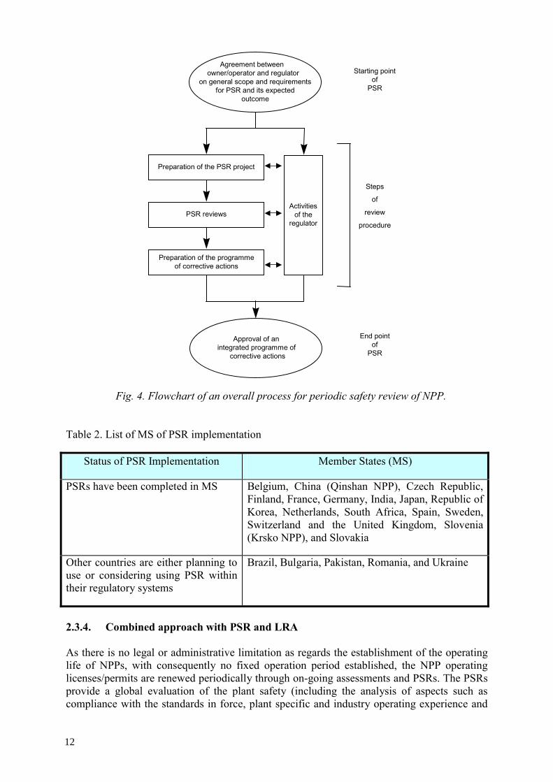
updating the safety evaluation and improvement programmes), and also the PSR is the main tool used by the nuclear regulatory authorities to establish the additional requirements for any new operating license period. In Spain, PSR is used as a basis for renewal of the operating licence for all NPPs. Safety Guide 1.10 of the Spanish nuclear regulatory authority (CSN) establishes the safety issues to be reviewed and resolved to obtain a new operating license for the next period. The regulatory process, based on on-going assessment and PSRs, includes the necessary mechanisms, and provides a reasonable guarantee that all aspects potentially affecting plant safety or public health are incorporated into the plant licensing bases. Conditions associated with an operating license in place state that, in the case of applying for a 10 additional years of operation, a new PSR must be performed and submitted to CSN for approval three years before the end of the current operating term. If the new operating period pertains to the operation of the NPP beyond the design life, the main objective of the new PSR will be to determine whether ageing of certain SSCs is being effectively managed so that required safety functions are maintained, and whether an effective AMP is in place for continued operation. Additionally, Time limited ageing analysis(TLAA) must be identified and evaluated in order to demonstrate that it will remain valid for the new period of operation. The scope of the PSR has been reviewed by the CSN in order to incorporate other aspects related with the continued operation beyond the design life. In order to accomplish this, it has been concluded that the best basis and most detailed international reference for establishing the fundamental requirements for renewal of the operating license beyond the design life is the US regulation 10CFR54 (LR). Therefore, the LR methodology constitutes the supplementary process that has been incorporated to the specific PSR to be performed when applying for a renewal of the NPP operating license exceeding the original design life. 2.4. REGULATORY ASPECT AND CONSIDERATIONS As discussed above, effective PLiM programmes should integrate both safety and operational performance concerns. Regulatory attention focuses on the former, with the primary interest being on obtaining assurances in effective ageing management of SSCs important to safety. In practice, the specific aspects of regulatory requirements and expectations differ considerably between member states. In general, however, they follow the guidance outlined in the IAEA safety standards, safety guides and technical report series [1–20] described in Section 1.4. The operating NPPs have been licensed on the basis of the requirements established during the design process. To demonstrate compliance with regulatory requirements, the day-to-day operating envelope must be maintained within the bounds of the assumptions of the plant safety analysis. These operating envelopes include: • Special / critical safety system setpoint limits and system availability. • Acceptable range of process parameters. • Allowable equipment configuration and operating states. Some examples of regulatory approaches and strategies for ensuring the implementation of effective and systematic ageing management practices are summarized in the following sections.
13
Fig. 5. Process for renewal of operating permit beyond design life time in Spain.
2.4.1. Regulatory approach in Canada Historical evolution
By the end of the 1980’s programmes were in place related to ageing, however a more comprehensive and systematic ageing management strategy was needed. As a result, in 1990, Canadian Nuclear Safety Commission (CNSC) staff requested licensees to demonstrate that: • Potentially detrimental changes in the plant condition are being identified and dealt with
before challenging the defence-in-depth philosophy; • Ageing related programmes are being effectively integrated to result in a disciplined
overall review of safety; • Steady state and dynamic analyses are, and will remain, valid; • Review of component degradation mechanisms is being conducted; • Reliability assessments remain valid in light of operating experience; and • Planned maintenance programmes are adequate to ensure the safe operation of the plant. The IAEA guidelines were accepted as an appropriate framework for such a programme. As a result of the above request, the Canadian nuclear industry put systematic ageing management programmes in place that were based on the IAEA guidelines. The specific processes and procedures developed in support for the ageing management plan varied from plant to plant, though a summary of the general approach is presented below.
– Cost benefit analysis for plant upgradings derived from new regulations analysis, proposed by CSN.
Current Requirements to Renew Operating License (within design life)
Long Term Operating Requirements (beyond design life)
Application
for Long Term
14
Using the guidance provided by the IAEA publications, utilities undertook efforts to identify gaps in their operating policies and procedures with regards to the ageing management of critical components. Initially discussions focused on the selection of critical components. Generally, economically “critical” components were incorporated as well as the safety critical ones into an overall plant life management programme. The CNSC accepted either approach provided the safety critical components are sufficiently addressed. Programmes were developed that considered the known degradation mechanisms of the selected components. Industry also considered operating experience to ensure that all mechanisms that had previously caused failures were addressed. The programmes already in place to deal with known degradation mechanisms were evaluated to determine their effectiveness. Coincident with the above activities, generic procedures for evaluating component and system ageing were developed, often in conjunction with the plant designer. Along with these, condition assessments of the major plant components were and are being performed. These assessments evaluated the feasibility, from a safety standpoint, of continued use of the components. Current regulatory requirements The CNSC has not issued explicit regulatory requirements on ageing management. However, a number of age-related regulatory requirements are included in several regulatory publications, including: • Class I Nuclear Facilities Regulations (requiring licensees to describe “the proposed
measures, policies, methods and procedures for operating and maintaining the nuclear facility”);
• Requirements for Containment Systems for CANDU Nuclear Power Plants (R-7); • Requirements for Shutdown Systems for CANDU Nuclear Power Plants (R-8); • Requirements for Emergency Core Cooling Systems for CANDU Nuclear Power Plants
(requiring that safety systems are available to operate when called upon, R-9); • Reliability Programmes for Nuclear Power Plants (requiring development of system
availability limits and minimum functional requirements, and description of the inspection, monitoring, and testing activities designed to ensure system availability, Regulatory standard S-98); and
• Other specific conditions of an NPP operating license. In order to address ageing, Canadian CANDU NPP utilities are required to inspect and perform material surveillance according to the technical requirements of CSA standards: • Periodic inspection of CANDU nuclear power plant components (N285.4), • Periodic inspection of CANDU nuclear power plant containment components,
(N285.5), • In-service examination and testing requirements for concrete containment structures for
CANDU nuclear power plants (N287.7), and • Technical requirements for in-service evaluation of zirconium alloy pressure tubes in
CANDU nuclear power plants (N285.8).
15
These requirements include inspection techniques, procedures, frequency of inspection, and evaluation of inspection results, disposition, and repair. Maintenance programmes are required for the purpose of limiting the risks related to the failure or unavailability of any significant SSC (See Table 3). In addition to the above, CNSC adopted industry fitness-for-service guidelines as regulatory means to address ageing management of the special components such as SG tubes and feeders. Future direction The CNSC has recognized that the current level of ageing management effort may need to be further augmented in order to ensure plant safety as Canadian NPPs continue to age. This will require strengthening the role of proactive ageing management utilizing a systematic ageing management process. As a result, the CNSC has undertaken the development of a regulatory standard on fundamental aspects of NPP maintenance programmes, which emphasizes the important role of proactive maintenance strategies. In addition, the CNSC has commenced the development of a regulatory document outlining the key components of ageing management programmes, recognizing that these are often integrated with economic factors into an overall PLiM strategy. 2.4.2. Regulatory approach in the Republic of Korea Korean nuclear industry follows the periodic safety review practice. In normal operating period before the plant design life, general PSR is reported to regulatory body every 10 years in accordance with IAEA safety guideline 50-SG-12 of PSR. For the long term operation beyond the design life, PSR should review plant safety including the ageing management for the continued operating period. Korea regulatory authority is trying to combine LR and PSR approach to take the synergy effect. 2.4.3. Regulatory approach in India After completion of the safety review, the license for the nuclear power plant is issued by Atomic Energy Regulatory Board (AERB) for its design life which typically is in the range of 30 to 40 years. Within the operating license, the Regulatory Body grants initial authorization for a specified period and renewal of authorization for further specified periods after assessment of PSR. AERB requires HWR owner/ operators to conduct PSR for renewal of authorization which include the following: • Cumulative effects of plant ageing and irradiation damage • Results of in-service inspection (ISI) • System modifications • Operational feedback • Status and performance of safety systems and safety support systems • Revisions in applicable safety standards • Technical developments • Manpower training • Radiological protection practices • Plant management structure, etc.
16
Table 3. Summary of Ageing Concerns in CANDU Power Plants
Inspection and tube plugging. Chemistry control, water-lancing and secondary side chemical cleaning, installing additional bar supports to reduce vibration.
PVC cable Radiation and temperature-induced embrittlement
Insulation failure leading to current leaks and short circuits
R-7. R-8, R-9, L.C. 7.1
Develop effective EQ programmes, procedural controls, test plans, visual inspection.
Maintenance, operating experience trending, new battery designs.
Orifice Flow erosion, material deposition
Loss of monitoring capabilities, consequent loss of control
R-8 Condition monitoring, alternative flow measurements.
17
This process of PSR for renewal of authorization is to be carried out every nine years within the design life of the NPPs. These PSRs are intended to further ensure a high level of safety throughout the service life of the plant. AERB has already prepared relevant guidelines in this connection as safety guides as follows: • In-service Inspection of Nuclear Power Plants (AERB/NPP/SG/O-2) • Surveillance of Items Important to Safety in NPPs (AERB/SG/O-8) • Renewal of authorization for Operation of NPPs (AERB/SG/O-12) • Operational Experience feedback for NPPs (AERB/SG/O-13) • Ageing Management of NPPs (AERB/SG/O-14)
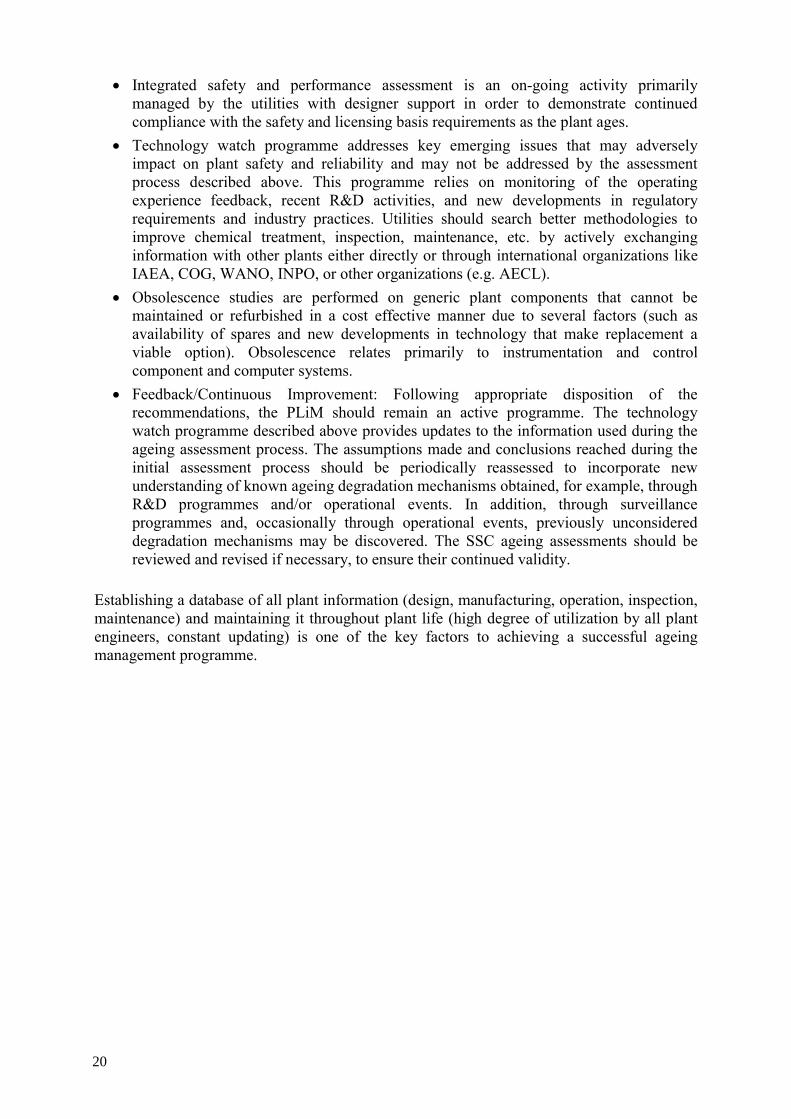
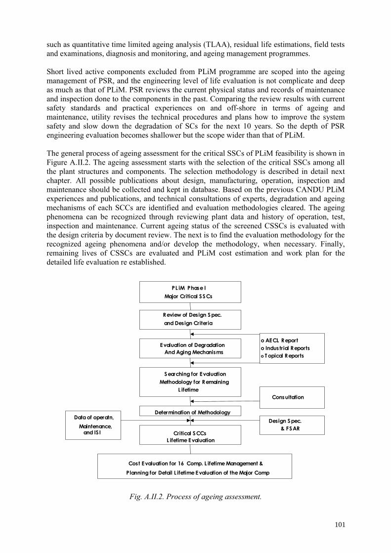
2.5. OVERALL INTEGRATED APPROACH An overall approach to PLiM is to consider all the issues relating to plant ageing in a fully integrated programme. Figure 6 shows an overview of a high level comprehensive approach, which determines whether the plant will continue to perform in accordance with the specified expectation or be forced to shut down, depending on several factors influencing the cost-benefit equation to restore the performance capabilities of the asset. The physical plant assessment focuses on the continuing ability of the structure or system, component to meet the specified performance criteria over its design life. If, in spite of maintenance and or refurbishment, a critical structure or component is deemed not likely to be able to meet its performance requirements, then a timely replacement must be undertaken with due consideration to the associated cost-benefits justification. Otherwise the plant is forced to shut down by default until the issue can be resolved satisfactorily. Similarly, if the institutional infrastructure is allowed to degrade beyond HWR owner/operator management criteria, then the plant will be forced to shutdown until the underlying issues can be resolved in a satisfactory manner. The issues related with institutional ageing are not discussed further in this report as they are primarily related to performance of the utility management. The various key elements of a life management programme for physical plant are shown in Figure 7 as follows:
• Screening: Screening/prioritization of systems and components to understand their importance. This will allow for the application of the appropriate ageing assessment procedures.
• Ageing assessment: Ageing assessments are methodologies used to assess the effect of degradation on SCCs and determine the appropriate inspection and mitigation techniques. They include:
• Condition assessment (CA): Typically for less critical systems, structures and components. The CA process may place related components in commodity groups such as instruments, and valves, where they are evaluated together. The methodology entails a general review of plant data in order to establish current condition and to evaluate ageing degradation at a component level. The CA report provides a prognosis for attainment of design life and/or long term operation with associated recommendations. Recommendations provide the technical basis for on-going ageing management of the subject structure, component or commodity and may identify a need for further assessment.
18
• Life assessment (LA): Performed typically for most critical structures and components that are generally passive in nature and typically designed not to be replaced as part of normal maintenance programme. This involves a rigorous assessment of all plausible ageing related degradation mechanisms. The methodology entails a detailed review of plant data in order to establish current condition and to evaluate ageing degradation at a sub-component level. Similar to a CA, the LA report provides a prognosis for attainment of design life and/or long term operation with associated recommendations. Recommendations provide the technical basis for on-going ageing management of the subject structure or component and may be used for economic planning.
• Systematic assessment of maintenance (SAM): This form of assessment makes use of Failure Mode Effect Analysis (FMEA) methodologies and information from internal and external feedback and R&D findings. It utililizes streamlined Reliability Centred Maintenance techniques, as modified for nuclear plant applications. It is performed for critical systems with emphasis on active components (that are generally designed to be replaced as part of the normal maintenance programme), in order to preserve the defined systems functions [29].
Fig. 6. Comprehensive approach to plant life management. — Physical plant and institutional assessment —
PLANT
Plant Life Management
Physical Plant Assessment
SC End of Life?
SSC Performance
Met ? Plant Available
For Service
Execute Replacement
Plant Not Available for Service
Institutional Assessment
Management Criteria Met?
DevelopRecovery
Plans
Replaceable ?
Cost/Benefits Justified?
Deficiencies Resolved?
N
Y
Y Y
Y Y
N N
NN
* SC: Structures & Components
19
• Integrated safety and performance assessment is an on-going activity primarily managed by the utilities with designer support in order to demonstrate continued compliance with the safety and licensing basis requirements as the plant ages.
• Technology watch programme addresses key emerging issues that may adversely impact on plant safety and reliability and may not be addressed by the assessment process described above. This programme relies on monitoring of the operating experience feedback, recent R&D activities, and new developments in regulatory requirements and industry practices. Utilities should search better methodologies to improve chemical treatment, inspection, maintenance, etc. by actively exchanging information with other plants either directly or through international organizations like IAEA, COG, WANO, INPO, or other organizations (e.g. AECL).
• Obsolescence studies are performed on generic plant components that cannot be maintained or refurbished in a cost effective manner due to several factors (such as availability of spares and new developments in technology that make replacement a viable option). Obsolescence relates primarily to instrumentation and control component and computer systems.
• Feedback/Continuous Improvement: Following appropriate disposition of the recommendations, the PLiM should remain an active programme. The technology watch programme described above provides updates to the information used during the ageing assessment process. The assumptions made and conclusions reached during the initial assessment process should be periodically reassessed to incorporate new understanding of known ageing degradation mechanisms obtained, for example, through R&D programmes and/or operational events. In addition, through surveillance programmes and, occasionally through operational events, previously unconsidered degradation mechanisms may be discovered. The SSC ageing assessments should be reviewed and revised if necessary, to ensure their continued validity.
Establishing a database of all plant information (design, manufacturing, operation, inspection, maintenance) and maintaining it throughout plant life (high degree of utilization by all plant engineers, constant updating) is one of the key factors to achieving a successful ageing management programme.
20
Fig. 7. HWR plant life management integrated process.
2.6. PLANT ORGANIZATION CONSIDERATIONS It is widely recognized that the success of a PLiM programme is very dependent upon the success in integrating the programme into the plant organization and its current activities and programmes. To launch a PLiM programme (if this has not already been done), the utility or plant should establish a PLiM group at the plant to develop a detailed plan specific to the utility organization. Then a PLiM pilot project (usually of 6 months to 2 years duration) is typically undertaken. The scope of the PLiM pilot project can vary but should include PLiM planning and some pilot ageing assessments, so that the utility PLiM team can gain significant level of experience and learning that will enable them to plan, perform and implement the full comprehensive PLiM programme. Also, procedures developed early in the PLiM Pilot Project should be updated with the experience gained in application from the pilot ageing assessments. In addition to the plant PLiM group, a successful PLiM programme requires effective interaction with other key plant staff and groups (during assessments, they need to provide the current operational history and plant programmes) and understanding by plant staff (typically
OBSOLESCENCE
Plant Systems, Structures and Components
Screening Process
Ageing Assessment ⇔ Systematic Ageing Management Process (Cycle)
Life Assessment (LA) • Rigorous Assessment • Typically for most Critical
Structures and Components
• Generally Passive Components
• Typically Designed not to be Replaced
Condition Assessment (CA) • Less Rigorous Assessment • Typically for less critical
Systems, Structures and Components
• Groups evaluated together
Systematic Assessment of Maintenance (SAM) • Rigorous Assessment • Typically for most Critical
Systems • Generally Active
Component • Typically Designed to be
Replaced
Technology Watch
21
plant staff perform a detailed review of the assessment reports). This helps the staff undertake “ownership” and eventually “Do” PLiM themselves. Typically, system and component engineers, maintenance and inspection staff, reliability groups and operators all have a role to play in PLiM. One important aspect is that understanding of the ageing assessments brings significant benefits to PLiM implementation. While various degrees of involvement of plant staff in assessments and implementation are possible, the objective is to increase the understanding of the “whys”, in order that adequate decisions can be made of what changes to make in plant programmes (these are the “hows”). Involvement of plant staff also helps identify the training needed for effective transfer of PLiM technology. For instance, training of plant staff in ageing degradation mechanisms and in assessment techniques is important to the transfer of PLiM technology to the plant to ensure effective implementation and “adaptation” to plant specific situations. Effective PLiM implies and requires some additional effort by utility staff as the plant ages. Hence, plant staff involvement in the PLiM programme does imply some additional responsibilities, but there are various ways to split the effort involved and the roles to minimize disruption to other day-to-day duties. The intent is to tailor the added effort to the specific utility or plant organization, which involves plant specific decisions. However, it has been recognized that before those decisions can be made, the experience of the PLiM Pilot Programme must be obtained. It should be noted that one of the recommended Pilot Project tasks relates to developing utility specific PLiM procedures. One of these is a plant specific station instruction (which is a high level plant policy publication) that spells out who has what role in the PLiM programme and the additional PLiM responsibilities of various groups. 2.7. TECHNOLOGY INFRASTRUCTURE Implementing a comprehensive and systematic PLiM programme involves systematic assessment technologies, detailed understanding of degradation mechanisms and of system/component design and supporting tools, procedures, and methods. For HWR plants, this programme has been developed and advanced via extensive development and implementation experience at various utilities over the past decade. Many lessons have been learned on effective interfaces between the various disciplines and the organizations that will be involved in performing PLiM work. Efforts continue to improve and update this knowledge base, as experience continues to grow with PLiM at various plants. In particular efforts are underway to organize the large amount of ageing-related data in an easily accessible fashion for current PLiM efforts but to retain the knowledge for future use in PLiM programmes. HWR NPP owner/operators and the design support organizations should work closely together on PLiM. Detailed and close collaboration at one plant can lead to on-going improvements, which can be applied to PLiM programmes at other plants or to better assessments within the same plant. There are many potential benefits of this collaboration to both parties.
22
For instance, design organizations can either undertake complete ageing assessments or support the utility ageing assessments; via direct experience in design, procurement, construction, commissioning and operations feedback from other HWR plants. Also a successful PLiM programme will utilize results from an active R&D support programme that focuses on plant ageing mechanisms, surveillance methodologies, mitigation methods, and improved inspection technologies. Another valuable input can come from the OEMs (Original Equipment Manufacturer) who often have the most detailed information on a particular SSC. A mature PLiM programme takes an industry approach and utilizes the best expertise from various organizations. 2.8. SUPPORTING DATA MANAGEMENT Effective PLiM of HWR NPPs implies more effective use of plant data trends using instrumentation and monitors that often already exist at the plants. Also the integrity of ageing related plant data is a significant concern in the nuclear industry. With the passage of time, retention, integrity, and accessibility of data histories within the plant culture and organization can become issues. Plants that start early on organizing data systematically will be better able to optimize their maintenance strategies. Hence, effective PLiM programmes also deal with plant data management issues to ensure high quality data for both current and future ageing/life assessments. For example, the ageing assessments on important fluid retaining SSCs show that the effects of chemistry are among the most important factors affecting degradation. To track these, an advanced system chemistry monitoring and diagnostic system can be used to advantage. For instance, to maximize steam generator tubing life, it is necessary to identify the effects of impurities in the secondary side water on local steam generator crevice chemistry and fouling. On-line access by the operators to current and past chemistry conditions (such as available from such advanced monitoring and diagnostic chemistry systems) enables appropriate responses and facilitates planning of shutdown maintenance actions (such as cleaning of specific areas). This is a significant means to successful management of health and long life of this critical plant component. As maintenance strategies move to more condition-based decision making, effective use of age-related information at the plant and the timely flow of this information to key decision makers becomes a greater challenge to manage. Each monitored parameter of importance to ageing will be used to determine when to take an appropriate action. Therefore, it becomes important to ensure that the appropriate personnel see the requisite information, and to track their response as follow up action is taken. It also means that personnel will be expected to deal with a more significant number of potential actions, so care must be taken to not simply overload them with information and requests. To facilitate these changes to condition-based decision making advanced maintenance information, monitoring, and control systems can be used to benefit. These types of systems provide an interface for users to access specific health monitor information and an electronic portal to the maintenance review and to the work management system. 2.9. HUMAN ISSUES RELATED WITH HUMAN AGEING MANAGEMENT 2.9.1. Availability of qualified NPP personnel Availability of qualified NPP personnel is an important issue for PLiM; this includes validated staff selection methods and organizational issues. Even if NPPs are technologically
23
at a high level they still require to be operated in a manner that conforms to safety prescriptions, technical specifications (TS), and good practices, which includes avoidance of transients, for example. However, due to the slowdown in new NPP construction, particularly in the West, over the last 20 years, there has been little incentive for young engineers to embark on a career in the nuclear power sector. Universities and other seats of learning have thus stopped or drastically reduced nuclear technology courses as a response to the falling demand. 2.9.2. Training and re-training — Knowledge management Training and retraining based on knowledge management is necessary to ensure that NPP personnel remain highly qualified to do their tasks. Programmes for initial and upgrades in training, including the use of simulators should be in place. These should also include the following aspects: Training in safety culture, particularly for management staff, the adoption of a questioning attitude, etc. Many NPPs will be entering their new licensing period, which may be regarded as being beyond the nominal design life, but not their technical life, thanks to PLiM measures. In particular, these highly experienced personnel not only possess detailed knowledge concerning the particular SSC they were responsible for, but also have a good general appreciation for the characteristic behaviour of the NPP as a whole. A factor in a NPP’s PLiM strategy must therefore be to ensure that sufficient replacement personnel are available and that the transfer of knowledge is guaranteed via adequate on-the-spot training and comprehensive documentation. 2.9.3. Personnel exposure to radiation Legal limitations are in place concerning radiological doses that NPP personnel may accumulate during a given period of time. Legally allowed doses are laid down conservatively such that they are not expected to cause any damage to health. An individual annual dose of 20mSv is such a value. Considering that AMP/PLiM activities may involve special circumstances that may lead to increased personnel exposure to ionizing radiation, it is essential that all such tasks are planned in advance with a view to limiting the dose. The concept of as low as reasonably acceptable (ALARA) must be rigorously applied. Shielding, distance and time spent on the activity must be optimized to create those conditions amenable to ALARA principles. Practice on mock-ups will facilitate a rapid and technically sound work programme. Therefore, radiological protection measures, where applicable, become an integral part of PLiM. 2.10. INTEGRATION WITH ECONOMIC PLANNING Effective PLiM involves the integration of ageing management and economic planning. As plants age and as HWR owner/operators make decisions on age management programmes and on investments to enhance plant reliability and predictability, economic planning must consider the current and future condition of the plant with regard to ageing. Most PLiM programmes that have been integrated with the economic planning decision making, utilize an economic model to evaluate operating alternatives for their HWR plants. For example, the following situations would typically be assessed with an economic model that includes the technical costs generated from the systematic ageing assessments:
24
• An evaluation of outage strategies – is it cost effective to add additional manpower (OM&A) to shorten the planned outage length (increase production)?
• An evaluation of the cost effectiveness of capital upgrades that can increase capacity or MCR (maximum continuous rating) and possibly increase the economic viability of a refurbishment.
• An assessment of when increasing operating and capital costs make a nuclear plant no longer financially viable.
• An evaluation of the additional value that can be realized by maintaining the option for continued operation.
• An assessment of the optimum economic strategy for a new plant design. For HWRs, economic models specific to HWR technology, licensing practice and electricity pricing practice, have been developed and are being used to optimise decisions on plant projects that involve PLiM. For instance, economic models have been developed with capabilities to handle single unit or multi unit sites, the pressure tube style reactor, re-tubing, and outages not linked to refuelling. Although repair/replacement for most SSCs is technically possible, ageing of most plant SSCs can indirectly impact on plant costs, because ageing-related behaviour can lead to forced outages, unplanned extensions to planned outages, reduced availability, and increased production costs. Measures to minimize ageing that involve system or component backfitting may be very expensive. For such measures, cost-benefit analysis will be necessary before making a decision. It must be noted that, when the plants get older, this type of cost-benefit analysis will require some assumptions about the planned plant service life. An effective PLiM programme should ultimately improve capacity factors by reducing the number of unplanned shutdowns and assist in defining strategies to lengthen operating cycles. PLiM can also be a major force in optimizing and even reducing plant OM&A costs when applied properly and early in the life of a plant. An effective PLiM programme also provides rigorous end-of-life estimates and long life strategies needed for economic and risk evaluation of repair/refurbish/replace options. PLiM is an important input into the long term strategic plan. This plan typically contains alternatives for long term operation, including shutdown at design life, or retube and extend life. Cost of other major component replacement and/or refurbishment is estimated and input to asset evaluation for each plant. Benchmarking (using experience from other plants) and/or system maintenance predictive models are used to estimate the change in maintenance costs with age. Alternative operating scenarios are analyzed, using discounted cash flow, to determine the alternative that creates the maximum value for the HWR owner/operator. Uncertainties (such as cost of licensing issues, major refurbishment, electricity pricing, future capacity factors) are addressed via an economic sensitivity analysis. In summary, the PLiM programme should be linked to the station business plan. While the primary aim of most PLiM programmes is to improve the availability and assure safety throughout HWR NPP service life, PLiM can have a strong influence (and likely improve) NPP profitability.
25
3. GENERAL APPROACH TO HWR PLiM 3.1. SCREENING SSCS Those SSCs that are to be included in a PLiM programme are usually identified by a systematic screening process, which prioritizes the systems based on their importance to achievement of plant goals, such as nuclear safety, environmental safety, and production reliability. In addition, structures and components whose failure would result in a major replacement cost or in a significant loss of production capability are also typically considered. The first steps in screening the SSCs are to customize the generic PLiM screening methodology for use at a specific plant. Standard criteria are safety, production, environmental impacts, worker safety and cost. A risk-based approach can be applied to develop the plant specific criteria, developing quantitative weighting measures, and then applying the plant specific screening process to the plant SCC list, to rank their importance. The resulting list of prioritised SSCs (sometimes known as the CSSCs – the Critical Systems, Structures and Components) will allow them to be included in the PLiM programme. Also the implied “residual” risk of not including other SSCs will be identified. The rigour of the ageing assessment, in terms of resources required and depth of evaluation will be determined by the SSC priority. In situations where parts of a PLiM programme are already underway without undertaking the up-front SSC screening, a systematic procedure for SSC screening should be used to verify that there are no gaps in identification of the remaining SSC assessments to be performed. The SSC prioritisation also assists utilities in identifying less critical SSCs. Figure 8 shows a typical level of assessment versus SSC criticality as determined by screening.
Several 1000's plantsystems, structures& components SSCs
y critical structures/ componentsz critical systems
3 potentially life limiting SSCs -SGs,FCs, feeders
((80 to 100)-y) components,(46 - z) systems in LCM
Remaining plant SSCs notimportant to PLiM
Fig. 8. Pyramid of PLiM SSCs.
Life Assessments,
SAM studies
Condition Assessments
Residual risk
26
3.2. LIFE ASSESSMENTS FOR CRITICAL STRUCTURES AND COMPONENTS For the most critical components and structures that provide mainly passive functions and are subject to long term ageing degradation mechanisms, life assessments are performed. Some of these key steps in the life assessment process and interfaces between the various groups are shown diagrammatically in Fig. 9. Typical CSSC life assessment methodology is based upon IAEA methodology, as detailed in [4]. A particularly important part of the process is to understand and assess the importance of all the ageing degradation mechanisms that can impact on the functions of the SSC. Another important aspect is to tailor the generic methodology, including the diagnostic and assessment methods and techniques, to the specific technology and characteristics of the SCC under consideration. Some typical examples and component specific considerations are given in the Appendices. Many components in the early HWR plants had a very good service record with little or no significant degradation history to date. However, this excellent in-service experience (and hence lack of degradation data) provides a unique challenge for the CSSC life assessments within the PLiM programme. In performing the systematic and detailed assessments, a key activity is diagnosis of the operational history for ageing indicators, as well as a thorough understanding of applicable degradation behaviour. With little degradation data from the plant, the challenge is to provide a reasonably comprehensive and detailed assessment of ageing effects for the next 20 to 30 years of operation. To meet this challenge, a thorough understanding of the applicable degradation mechanisms and the associated —“stressors”— is used. This understanding derives from research and development programmes, integrated with knowledge from relevant field data of other plants. An in-depth understanding of the plant operational history and the current plant programmes related to ageing are both key inputs to the life assessment process. Involvement of utility staff in the process is encouraged. Developing an efficient and effective team selected among key utility staff (such as ageing management experts, system engineers, component engineers, reliability engineers and maintenance personnel) contributes significantly to success and value of the PLiM assessment programme.
27
Fig. 9. Life assessment process and interfaces.
3.3. CONDITION ASSESSMENT OF STRUCTURES AND COMPONENTS AND
COMMODITIES Typically, the PLiM programme has an initial focus on a relatively small set of critical structure and components. As mentioned, for the most critical SSCs, life assessment processes are typically used. The CA process can be applied to less critical components and commodities. Some utilities are using an on-going CA process, and using CA outcomes as an input into their plant/utility business planning processes.
Identify degradation mechanisms
Provide understanding of degradation behaviour
Review design fabrication for age-sensitivity
Diagnose SSC for ageing stressors
Provide operational history
Assess O&M effectiveness for ageing management
Prepare life prognosis
Identify implementation for LTO
Further R&D
LTO business case
Implement ageing management change
Provide current ageing programme
R&D Engineering Utility
28
3.4. CRITICAL SYSTEM ASSESSMENTS PLiM assessments have typically focused on passive major components. However, a comprehensive PLiM programme will address all SCCs that represent a potential risk to the plant that warrants mitigation as evaluated in the screening process discussed above. However a large number of components subject to degradation may still require some level of assessment from the point of view of the functionality of the system. These components are best dealt with in the context of a system assessment. The development of a comprehensive PLiM programme will also ensure that degradation mechanisms are assessed as they relate to specific ageing management strategies, executed as the preventive maintenance (PM), condition based maintenance (CBM), predictive maintenance (PdM), surveillance, inspection and testing programmes of the plant. To achieve this goal, two assessment strategies are available; namely systematic maintenance planning (SMP) assessments and condition assessments of system. These two processes are both capable of dealing with degradation, however, CA is usually applied to components subject to longer term degradation (passive components) while the SMP assessment methodology is usually more efficient at assessing components subject to short term degradation (typically active components). 3.4.1. Condition assessment of systems Condition assessment (CA) of systems addresses the system perspective as it applies to understanding the current condition and provides indications about future behaviour. A standard has not been identified for system CA, but the process follows logic similar in many ways to that for SMP assessment. The assessment includes screening of components captured within the boundary, and can address all components types. The screening provides a means of identifying those components requiring a greater focus for the balance of the assessment. The specific ageing assessment sections of the process consider components or groups of components, following the processes identified in the component CA discussed further below. In many cases, SCCs will be assessed under individual component CAs or LAs depending upon their criticality. The system CA brings the overall results together from a system perspective. The system CA focus impacts on the level of effort and the content. For PLiM programme CAs, there is interest in reviewing the ongoing programme to address ageing elements, together with understanding the current condition of the components. The screening typically performed reflects the impact of component failure on safety and production. The report provides a technical basis for improvements to the maintenance strategy, identifies short term requirements to confirm the prognosis, reviews potential obsolescence issues, and provides a prognosis for the service life period under consideration. The technical basis is developed through consideration of susceptibility to ageing related degradation mechanisms (ARDMs), review of the current status with regard to the ARDMs of interest, and a review of existing programmes to identify and mitigate these ARDMs. For CAs focused on a specific need, such as defining elements of refurbishment, those items handled by normal maintenance would require less scrutiny. Typically the overall assessment ensures there are no issues associated with the maintenance trends and obsolescence, and gives a prognosis whether the component should be replaced during the refurbishment outage. The assessment relies on the review of ARDMs as discussed above.
29
3.4.2. Systematic maintenance planning (SMP) assessments The generic term of SMP assessments is used to reflect a number of assessment techniques most commonly referred to as reliability centered maintenance (RCM), streamlined RCM (SRCM), and preventive maintenance optimization (PMO). This systematic assessment, combined with input from the various specialists, provides elements for establishing the maintenance basis as described in INPO AP-913 “Equipment Reliability guideline” that is becoming widely used in the nuclear industry. The goals of these assessments are: • To develop a documented technical basis for the overall maintenance strategy
associated with each component considered. This provides the foundation for a programme that is adaptive throughout the life of the plant.
• To ensure that a sufficiently comprehensive maintenance strategy is applied to components to achieve the safety and operational goals of the plant.
These goals have a significant impact on the choice of assessment technique. Users need to assure themselves that the assessment process they choose will not result in insufficient maintenance being specified. There is a real possibility, through the application of various assumptions inherent in some techniques, to specify incomplete or ineffective maintenance. Similarly, regardless of the rigor inherent in a given technique, there is the potential to make non-conservative decisions while attempting to streamline or reduce the overall effort. In addition, these techniques provide the opportunity to refine the maintenance strategy for each component in order that a plant might optimize the maintenance plan such that only the right maintenance is performed on the right component at the right time. There are several methods or approaches to applying these techniques. The key is that the process be systematic and rigorous and address the goals noted above. Whether done by single assessors, teams led by facilitators, or expert panels, they need to always follow the same overall process. This includes documenting the results and providing sufficient background to understand the basis of the maintenance strategy to be implemented. This basis needs to include an understanding of the components functions within the context of the system and the systems function within the plant. The application of SMP assessments does allow for plants to focus on areas of highest risk first, especially when working with limited resources, while meeting the goals above. The system screening provides a focus on more critical systems. Within the system assessments, further focus can be achieved through the inclusion of a criticality evaluation step, typically a feature of streamlined techniques and part of the INPO AP-913 process. The criticality evaluation can be simplified through focus on major components within a system. The criticality is based upon the failure effects attributed to the component. Other simplifying techniques, such as applying a maintenance strategy, as developed for one component, to group of similar components, is not uncommon, but is a practice that needs to be carried out carefully. Even if the component for which the strategy has been developed is highly critical, the context of operation (e.g. system function) and environmental considerations need to be applicable to the entire group. Assurance is needed that the failure modes of interest are common across the entire group of components. These cautions derive
30
from the intent of meeting the goals given above. The following are some examples of CANDU 6 systems have been assessed using this technology: • Four containment systems (dousing, containment isolation, airlocks, Class III local air
coolers); • Auxiliary and main feedwater and condensate systems; • Class III standby and emergency power supply diesel generators and auxiliaries; • Emergency core cooling; • Instrument air; • Moderator and auxiliaries; • Main heat transport and auxiliaries; and • Shutdown cooling systems. 3.4.3. Alternative approach to systematic maintenance planning: The “expert panel”
maintenance programme approach In case limited resources were available, an alternative approach can be adopted after enough operation records have been acquired. The process, as described below, is based on an expert panel approach and may make use of industry knowledge base or maintenance templates (if available). Close collaboration of various departments within the power plant is essential to the success of this method. Following are the main steps: (1) Identify key equipment and components in critical systems (contributors to systems
functional failures) and create a database (2) Group key components by type and technical characteristics and identify applicable
preventive maintenance tasks, using manufacturer recommendations and current station practice.
(3) For each type of equipment, assemble a panel of engineering, maintenance and operation experts to carry out a comprehensive and systematic review of current preventive maintenance comparing it to manufacturer, industry knowledge base and determine the most appropriate maintenance surveillance and inspection tasks and their frequency.
(4) Collect and summarize the expert panel recommendations for preventive maintenance programme enhancement (new tasks, revised and/or proposed for cancellation) and issue final reports (customized preventive maintenance templates for each type of equipment and component)
(5) Review existing maintenance work orders and procedures accordingly. 3.5. OBSOLESCENCE In time, plant components become outdated and they cannot be adequately maintained without compensatory actions to mitigate the effects of their obsolescence. From this perspective when key components from process systems are obsolete, the system health is at high risk of deterioration. A systematic obsolescence mitigation programme comprises 3 phases: • Preliminary identification of equipment obsolescence • Obsolescence assessment and resolution (evaluation, identification of alternatives,
definition of implementation strategies and resolution) • Develop a replacement programme and prioritize upgrade/replacement solutions.
31
Many NPPs are currently operating using programmemable electronic systems and equipment. Future NPPs and retrofit projects will also use these types of devices, which are the state of science and technology solution for I&C. The life cycle of such equipment has to be considered, taking into account the specific characteristics of electronic information technology (IT), and not be limited to the aspect of ageing of components (hardware). Analog and digital electronics used to convert the sensor signals should be included in the management of I&C ageing. This equipment has not, in the past, been the subject of ageing concerns because they are normally located in instrument cabinets in the easily accessible and environmentally benign areas of the plant and consequently age very slowly. However, obsolescence of this equipment is important, especially when it relates to LTO. Obsolescence is more of a problem with this equipment than ageing, because electronic components and digital systems are frequently upgraded by manufacturers, and older equipment is no longer available. Consequently, in the focus of ageing management for such systems, it is necessary to ensure that the required functions are met independently of the I&C technology applied. Thus, the ageing of programmable electronic devices is to be considered within the concept of LTO, and maintenance of equipment, considering both hardware and software facets, and the human/organizational associated consequences. 3.6. LEARNING FROM EXPERIENCE 3.6.1. Operating experience feedback Sharing of experience and learning from operating experience (including errors), from R&D programmes and the assessment of performance trends should be used as input to an effective PLiM programme. However, relying solely on a “learning by mistake” strategy is not advisable, because it involves reliance on “unanticipated ageing” and unanticipated ageing is costly. It generally requires more extensive equipment refurbishment and costs replacement power, if it causes a forced maintenance shutdown. Examples of unanticipated ageing are: • EWS spray header erosion in CANDU 6 • Feeder thinning rates and higher flow assisted corrosion of carbon steel • Pressure tube Spacer shifting and repositioning • Pressure tube creep rates higher than anticipated. • Steam generator (higher than anticipated deposition rates, divider plate accelerated
leakage rate) If unanticipated ageing (learn by mistake attitude) remains unchecked, it has the potential to also adversely affect safety, due to undetected changes in equipment condition and it tends to produce “institutional or safety culture degradation” as well. 3.6.2. Technology watch Plant ageing if uncontrolled may increase the probability of failures, possibly leading to accidents. Examples of safety implications of unchecked ageing are hydrogen pickup during normal operating conditions (NOC), the formation of hydride blisters on the pressure tube
32
leading to pressure tube rupture, PT sag leading to PT/CT contact, flow assisted corrosion (FAC) in piping and outlet feeders, leading to leaks and breaks. There are failures that are not covered in reliability studies. These are failures that typically go undetected and therefore unpredicted by system testing such as in the case of the MOV torque switch settings. As friction increases settings are increased and may be increased to the point where the motor seizes or other system failures occur. Another similar instance is instrument loop reliability and the effects of the instrument error on performance and safety. Signal drifts, as the instrument ages, may lead to out of specification signals and failures, for example neutronic instrument dynamics and response. Safety system settings can also be affected by ageing due to changes in process conditions (trip margins). Similarly, during an accident, safety system settings can be affected by the ageing state of the equipment and by changes due to the progression of the accident itself such as the case of the pressure tube (PT) blisters, stress corrosion cracking (SCC) of boiler tube and subsequent leaks, cable deterioration due to radiation exposure, material properties (affecting their ability to withstand failures), PT diametral creep creating flow redistribution in the core, bundle bypass, etc. whereby the critical channel power (CCP) effect is initially positive and then goes strongly negative. 3.7. REFURBISHMENT While the word “refurbishment” is often applied to actions taken at any point during HWR service to return a SCC to its original functional capability, in this report “refurbishment” means those actions taken near end-of-design life, for HWR PLiM.
The key element for HWR PLiM is fuel channel replacement (FCR), as there are known degradation mechanisms that will limit the life of the pressure tubes. The overall approach is to perform both the FCR work as well as any other necessary refurbishment work. The FCR work is also an opportunity to refurbish other HWR systems or components to ensure that an extended service life will be achieved without the need for another extended outage.
During the planning period, assessments and plans are made to identify the detailed scope of those specific systems, components and structures for which the FCR outage provides the most economic opportunity to inspect and maintain or replace. It is important to clearly define the required work scope upfront in order to ensure that the FCR outage duration is not lengthened or burdened with the cost of maintenance work, which could otherwise be accomplished during future station outages. PLiM planning establishes the timing of replacement of major pieces of equipment so that estimates can be made of the expenditures to be expected during the refurbishment project and subsequent operation. One process to identify what work is required consists of the following steps: (1) Definition of scope — Typically, the process starts with a complete listing of all the
SSCs that constitute the “plant” (such as the subject index (SI) listing, typically consisting of over 1000 items). These are reviewed to eliminate SIs that are not relevant to safety or power production.
(2) Work breakdown — The SIs selected for review are grouped into common subject areas. These common subjects are then divided up into subcomponents corresponding to the disciplines involved and the responsible organizations.
33
(3) Confirmation of SSC lists — The equipment database from the NPP is used as the basis for defining all the component parts that are addressed for each CA report. However, experience has also shown that these databases may not be sufficiently developed in all areas to be used as a reliable basis for the CA. Therefore, confirmation of the SCC list for each system may be required based on Design Manuals, Operating Flowsheets and other relevant information.
(4) Screening — The next step is to screen out from the CA process all items that are normally replaced in the plant as part of current maintenance programmes. Items were removed from further consideration if: • The devices can be out of service for short periods of time without requiring plant
shutdown • Work order history revealed no problems resulting in unit outages • Devices can be isolated for easy refurbishment/replacement • Devices are readily accessible • Replacement of devices does not require significant capital or maintenance costs • Replacement of devices is possible on power or during a normal outage • Replacements/spares are part of existing inventory or readily available
(5) SSC health prognosis – Items that are not screened out are subjected to a detailed
assessment process consisting of the following items: • Review of the SSC design basis • Review of historical operational and maintenance data, primarily the work order
history, supplemented by system engineer interview • Identification of ageing related degradation mechanisms and evaluation of the SSC
against each relevant mechanism. • Identification of any known obsolescence issues • Generation of conclusions about the health prognosis for the SSC and recommendations.
Any decisions made are retained in a database for later implementation. Using a systematic process such as the one described above should result in a highly effective and auditable process to scope the refurbishment work. 3.8. INTEGRATED SAFETY PERFORMANCE ASSESSMENTS 3.8.1. Overview of integrated safety performance assessments To properly set up a PLiM driven action plan, compounded effects of interfacing ageing components and systems must be considered. For example PT creep must be considered in concert with the other PHTS ageing mechanisms and effects such as boiler fouling, increased resistance in the boilers, effects on reactor overpower (ROP) and bundle power and channel power limits, evolution of the inlet feeder temperature, heat transport system asymmetries, effects on Steam Generator pressure and on critical channel power limits. A corrective maintenance plan should be devised in view of the overall objectives. For example PLiM results may suggest boiler divider plate change out, steam generator cleaning, ultrasonic flow measurement (USFM) both cold & on line, trip calibration, use of high performance fuel to restore original design margins, but all these suggestions must be vetted in the context of overall performance, safety parameters and operating margins, etc.
34
Stations may be required to incorporate effect into ROP set point and perform detailed assessment for ROP, time to contact studies, studies to determine the effect on Reactor control, on bundle power and channel power (BP/CP) affecting uncertainties & limits, shutdown system effectiveness for LOCA and in-core breaks. 3.9. PLANT LIFE MANAGEMENT IMPLEMENTATION Once progress has been made on the ageing assessments, it is important to implement the disposition of recommendations into plant programmes. Effective plant practices in monitoring, surveillance, maintenance, and operations are the primary means of managing ageing. From general experience with HWR PLiM programmes, it can usually be expected that the ageing assessment programme will lead to modifications and enhancements, but not necessarily replacements, of the pre-existing plant ageing programmes. However, a successful PLiM programme is measured by the plant performance indicators. This requires a structured and managed approach to the implementation process. The overall objective is to optimize plant programmes for ageing management, both for the remaining design life period and for the plant long term operation. First, the recommendations for changes to current plant programmes that result from the ageing assessments are systematically dispositioned. Following this, PLiM implementation strategy may be developed on Table 4. In this step, plant staff considers the implementation options (implementation procedures, cost-benefit analysis, schedule & outage plans, affected departments, task responsibilities, work priority, etc). PLiM changes are then input to outage and operational planning process.
Table 4. HWR PLiM Phased Approach
Phase Scope
1. PLiM assessment programme
• Screening of plant systems, structures and components
• Life and Condition Assessments of critical components and structures
• Critical System Assessments of Maintenance • Technology Watch planning • Advanced technology development
2. Plant life attainment programme
• Plant specific detailed inspection and residual life assessment of key components
• Implementation of plant monitoring and surveillance ageing management programmes
• Enhancement of plant inspection and maintenance • Technology Watch implementation
3. Long term operation programme • Plant Condition Assessment • Replacement component strategies and planning • Assessment of regulatory and safety related design
changes for extended operation • Rehabilitation/ Replacement programmes for
components identified in CSSC studies or from inspection in plant life attainment programme
35
3.10. LONG TERM OPERATION PLANNING LTO requires careful planning and scoping and several HWR utilities have already started the detailed planning of a plant LTO programme. The HWR utility would normally initiate a detailed LTO study at their particular plant many years before the end of design life in order to optimise effectiveness and cost, and to maximize asset value. The end product of this study is a business case that compares the costs of LTO for their NPP with the costs of the alternatives. Typically, for HWRs, LTO involves a plant refurbishment, which includes pressure tube, calandria tube and partial or complete feeder replacement. Planning of these replacements is part of the LTO study work. Planning is also started for the environmental, safety and licensing issues that would need to be addressed to ensure safe and economical future operation of the unit. In addition to these studies, a systematic review of the plant SSCs is carried out to determine what other equipment refurbishment or replacement will be required due to ageing or obsolescence. A key part of an LTO programme is to utilize the outcomes of the PLiM ageing assessments and implementation (Phase 1 and 2) in enhancing current plant programmes for extended operation. For instance, the life assessment work on the concrete containment has led to an enhanced inspection and monitoring programme at one HWR NPP. With knowledge from the containment condition assessment programme at the decommissioned Gentilly 1 plant, a detailed containment ageing management programme (including the monitoring instrumentation) for LTO was developed. The detailed life assessment work lays the foundation for the plant inspection, maintenance and operational programme enhancements to extend the life of critical equipment. In general, ageing assessments provide the primary inputs for determining the work necessary for LTO, and for planning the optimized surveillance, maintenance, and operations programmes to achieve the utility’s targets for safety, reliability and production capacity during its extended life. Significant progress in Phase 1 and 2 of the PLiM programme provides the HWR utility with important in-depth assessments (and often with promising life prognosis) for key SSCs. These outcomes are important inputs into utility decisions to embark upon LTO. The following list of actual recommendations was identified during one LTO study and gives an idea of the potential scope for an HWR LTO project: • Station control computers — The control computers are obsolete. The original equipment
supplier stopped making this equipment many years ago. In order to complete an additional 25 to 30 years of life, some action is needed to replace this equipment in view of the potential for declining reliability and difficulty in getting spare parts.
• Programmable digital comparators (PDCs) — The PDCs are used in the reactor shutdown systems. The issue here is quite similar to the control computers and replacement will be required to complete the refurbished life.
• Main generator — The windings of the generator have a limited life insufficient to last throughout the refurbished plant life. Several options need to be studied including replacement with a new generator and rewinding of the existing generator. Similarly, many of the generator auxiliaries will need to be addressed to ensure reliable operation after refurbishment.
36
• Safety improvements — In parallel with the plant physical assessment, work has been done to establish what design changes may be required to minimize regulatory concerns with future plant operation. A number of changes to improve reliability and functionality of systems and components are being studied in more depth to establish what safety benefits would come about if such modifications were made.
• Reactor component analysis — Recommendations have been made to analyse component parts of the reactor to deal with ageing issues. Parts of the calandria are to be analysed to better establish material ductility limits. Moderator nozzles are to be analysed for potential fatigue issues. Analysis is to be done to establish more clearly the source of the reactor vault leak.
• Reactor component inspection — The analyses discussed above will be supplemented by inspections during the refurbishment outage. This outage will provide a unique opportunity for these inspections, as the reactor will be without fuel, fuel channels and moderator during part of the outage.
• Balance-of-plant (BOP) components — While most of the BOP components are much easier to inspect and replace than those in the nuclear steam plant (NSP), some further investigation is underway on those BOP components whose ageing are important to long life of the NSP.
For this particular plant, the steam generators were deemed to be in good condition and have a good prognosis for 50-year life provided the detailed recommendations from the LA were implemented. Typically, additional inspections are planned on steam generators in order to gain more confidence, such as in the assessment of secondary side internals. Some piping replacement may be necessary to address flow accelerated corrosion (FAC) issues. The ageing assessment studies for other critical systems, structures and components were completed and the results factored into the LTO programme as appropriate. 3.11. REGULATORY CONSIDERATIONS FOR LONG TERM OPERATION Some of the emerging regulatory issues that need to be addressed for long term operation include: • Potential increased requirement for safety analysis. • Incorporating or accounting for all ongoing ageing degradation in the safety analysis. • Resolution of a number of generic action items requiring possible modifications. • Possible need to maintain an updated PSA. • Evolving requirements for human factors engineering analyses. While the codes, standards and regulations in effect at the time of plant design and construction continue to be the basis for licensing, some changes and upgrades to meet new requirements may be needed to support LTO. As the plants establish the scope for LTO, it is important for the utilities to: • Maintain accurate records of the design basis including the modifications installed since
in service (configuration management). • Obtain a documented agreement with the regulator for the licensing basis for operation
beyond design life (such as 30 years). • Clearly identify any modification or enhancement to satisfy the licensing basis.
37
3.11.1. Overview of the Canadian regulatory position on long term operation In recent years, Canadian utilities have completed several refurbishment projects, notably restarts of reactors following a long term shutdown. The scope of these projects depended both on the age of the plant, and on the projected operating life following refurbishment. The projects to date have been carried out within the existing Canadian nuclear regulatory framework and the operating licenses issued by the Commission for each facility. Key regulatory goals for LTO projects are obtaining assurance of the adequacy of the scope of life extension and safety upgrades proposed by the licensee and verifying the proper execution of that work by the licensee, prior to return of the unit to service. In order to meet these goals, the CNSC specifies requirements for the LTO scope of work that is prepared by the licensee, assesses the proposed work scope, evaluates the licensee programmes for the control of all activities and evaluate engineering submissions, procurement, construction and commissioning carried out. The following steps will be required of licensees in establishing the scope of work: • Perform an environmental assessment (EA) pursuant to the Canadian Environmental
Assessment Act, which involves:
• An assessment of the environmental effects of the project, including the environmental effects of malfunctions or accidents that may occur in connection with the project and any cumulative environmental effects that are likely to result from the project in combination with other projects or activities that have been or will be carried out;
• The significance of these effects; • Comments from the public; • Measures that are technically and economically feasible and that would mitigate
any significant adverse environmental effects of the project; and • Any other matter that the CNSC requires to be considered.
• Carry out PSR activities, which is considered an effective way to obtain an overall view
of actual plant safety, in order to determine reasonable and practical modifications that should be made in order to maintain a high level of safety and to improve the safety of older nuclear power plants to a level approaching that of modern plants.
• Develop an integrated implementation plan for safety improvements, which involves the development of an integrated implementation plan for the necessary corrective actions, safety upgrades and compensatory measures to ensure the plant will not pose an unreasonable risk to health, safety, security and the environment and will conform to Canada’s international obligations over the proposed life. All generic action items and station specific actions items will be reviewed and each will be resolved to the extent practicable.
In assessing the adequacy of the proposed LTO workscope, CNSC staff reviews the Environmental Assessment Study Report and the Periodic Safety Review report, and takes into consideration information gathered through its own regulatory oversight activities. The CNSC notifies the licensee of its assessment of the proposed workscope, either accepting it or requiring changes. Subsequently the licensee proceeds with execution of LTO activities.
38
Once LTO activities are underway, the licensee is required to have acceptable programmes for the control of all LTO activities. Regulatory verification of project execution includes assessment of engineering change submissions, and inspections of licensee procurement, construction, and commissioning activities. Engineering change, procurement, construction and commissioning are to be performed in accordance with CNSC requirements and appropriate industry standards. During the refurbishment phase the licensee submits updated safety analysis that demonstrates the acceptability of the refurbished plant. The analysis must be submitted in time to allow for CNSC staff review prior to making recommendations on restart to the Commission. The CNSC expects that the licensee carries out a thorough commissioning plan for a LTO project. The scope and depth of this plan need not be as extensive as it would for a new facility, however, the baseline and confirmatory data must exist. If relevant system baseline data is available from past commissioning, then it can be referenced. However, if commissioning baseline data is no longer available, it will have to be reconstituted. 3.11.2. Overview of the Korean regulatory position on long term operation Korean government noticed the rule of LTO requirements for the PWR power plants, Guideline of Technical Criteria for the Continued Operation of Reactors beyond Design Life in October 2005. HWR requirements are not declared but are under review on the basis of the same technical philosophy as the PWR approach. In order to fix HWR requirements for LTO, further discussion and communication is expected in Korean industry in near future. Korean Industry expects that the HWR LTO rule will incorporate the experiences from PWR regulations and international HWR practices in the frame work of PSR. Application of lessons learned PWR regulatory experiences to HWR plants could be a strong point of Korean nuclear industry. 3.12. PLiM AND POWER UPRATE Longer life and increased output may be both attractive objectives for HWR owner/operators. Both objectives could potentially be achieved, with a variety of measures. It is important to note that these changes must not degrade existing safety margins or result in unacceptable environmental impacts. Some of these measures impact the CANDU nuclear steam plant (NSP) that others that apply more to the balance of plant (BOP). The PLiM programme has an important role, both with the LTO and to power uprate, described below. CANDU power uprates can involve fuel improvements (more heat generation), operational changes that mainly involve equipment improvements (for greater cycle efficiency) and operational changes that mainly involve improvements to plant maintenance, surveillance and inspection (for greater durations between outages). Usually combinations of these changes are considered. The technical and business case for implementing these changes must take an integrated approach and assess the impact of component life and performance, as well as the economic return-on-investment. It also involves the regulator if the changes impact on licensed conditions. The assessment of changed conditions on component life is typically where the PLiM programme for these components is important and useful. Systematic ageing assessment processes in combination with any previous PLiM assessments are used to assess the revised
39
operational conditions for the component of interest. The specific components that are assessed vary and depend upon the type of power uprate being considered. Typically it could involve the fuel channels, feeders, steam generators, turbine-generators, boiler feed pumps, moisture separator reheaters and the condensers as well as a variety of electrical equipment. Some of the proposed changes could potentially impact system operating margins. These impacts must be assessed. Any ageing issues related to these systems (or important components within these systems) must also be considered. An example would be boiler feed pump vibration. If current performance (prior to power uprating) is marginal, then the proposed power uprated conditions must be carefully assessed. For example, one might first think that this would make the current situation worse but it might actually improve performance (for instance if the changed condition moved pump operation to a better point of the pump performance curve). Assessing the power uprate changes is not just technical but also involves a detailed economic assessment. Usually the proposed changes are grouped into several packages. Then the net present value (NPV) of each package (say Option A, Option B, etc) is evaluated and compared to a base case. The economic calculations include parameters that affect the electricity generation value. Some of these are electricity price, fuel cost, Operations, Maintenance and Administration cost (OM&A) and capital cost. The recommended option is the one that provides the greatest improvement in net present value (NPV) over the remaining plant life, compared to the base case, provided the associated technical risks are acceptable.
40
4. CONCLUSIONS AND RECOMMENDATIONS 4.1. CONCLUSIONS This publication provides an overview of the various PLiM methodologies, technologies and processes for HWRs. Implementation of a systematic and comprehensive PLiM programme, such as that outlined in this report, goes a long way towards meeting the overall goal of HWR owners/operator to successfully achieve design life and LTO. • PLiM programmes should integrate and improve current plant maintenance,
surveillance and inspection programmes as these programmes are the primary means for managing ageing processes.
• PLiM programmes serve to aid in the development of sound technical and economic bases for the attainment of design life and preserve the option for LTO. PLiM will facilitate conditions where LTO becomes a realistic option in terms of safety and economics.
• PLiM programmes may be generally planned using experience from NPPs worldwide, but plant–specific PLiM programmes are required. While there are elements of HWR PLiM that are generic, it should be recognized that each NPP is unique and hence, this uniqueness of plant history and its ageing-related programmes need to be considered in detail.
• Effective PLiM programme is aided by complete and accurate documentation on important SSCs. This includes information on SSC design, materials, treatments, manufacturers and modifications. Comprehensive documentation allows operators and regulators to follow the progress of ageing and the effectiveness of any mitigating actions in NPPs.
• Data keeping of a complete set of baseline inspection/testing data for critical SSC’s is an essential prerequisite to allow trend analysis and prediction of critical SCC’s remaining service life for an effective PLiM programme.
• PLiM programmes are dependent on the availability of qualified, well-trained NPP personnel with a questioning and interactive attitude.
• Operating experience is an important element of effective NPP’s PLiM strategy. • Historical inspection, testing and operating data related to critical SSC’s shall be
available for a long period of time because such data are used as input for life assessment, condition assessment and LTO studies. HWR owner/operators must monitor and respond to rapid changes of software and hardware technology in order to maintain availability of essential data for PLiM and LTO Programmes.
• Knowledge management is essential for safe and economical operation of NPPs, especially so for LTO.
• R&D is essential in such an evolving sector as NPP ageing research. It is necessary to continuously investigate the ageing phenomena and mitigating measures by enhancing the evaluation technology and inspection techniques, as well as collecting actual plant data and knowledge obtained from R&D results. Regulators and operators must be aware of R&D results concerning ageing of SSCs, and their impact on safety and economic issues.
• For new designs, PLiM technology should be considered during the design phase, and carried on through construction, commissioning and operation.
41
4.2. RECOMMENDATIONS • Management systems envelops all elements of plant performance, safety culture and
PLiM programme. Degradation in the management infrastructure will thus impact the total business plan.
• Proactive and continually improving trend in safety performance of the plant, upgrading and maintenance of human resources is essential for PLiM and LTO.
• PLiM programmes hould be linked to the station business plan. • Each HWR owner/operators should implement a systematic and comprehensive PLiM
programme at the earliest possible time in the life of the plant, to provide on-going assurance that ageing effects are adequately addressed and traceable. Tighter exchange of information on PLiM methodology, OPEX and practices is beneficial to LWR and HWR owners/operators
• Periodically, review the programme in light of the progress achieved or assessment made and experience gained. As and when necessary, refine/revise the plan.
• PSR should be used as an efficient tool for PLiM programme for LTO. • All necessary documentation should be validated to confirm the current plant
configuration. Documentation management is an important task within PLiM. Some utilities have a configuration management service dedicated to this activity in their organization.
• It is important to also recognize that the reliability of secondary side SSCs will become important as NPPs operate for PLiM. Although such SSCs may be adequately managed for ageing effects (e.g. replacement), their contribution to overall costs have to be considered in the business case for LTO. Extensive replacement and refurbishment tasks may become common place in the future.
• Operators should obtain regulatory feedback on their PLiM programmes in order to ensure safety issues have been duly considered.
• A good practice for transferring technical excellence is to involve NPP employees during major replacement projects within PLiM under the leadership of experienced personnel. Young employees will thus be motivated to acquire essential knowledge through participation.
• The HWR owners/operators of the new plants should consider the scope of commissioning and inaugural inspection programmes and extend it as required to meet the PLiM programme prerequisites.
42
REFERENCES
[1] INTERNATIONAL ATOMIC ENERGY AGENCY, Proc. 1987 International
Symposium on Safety Aspects of the Ageing and Maintenance of Nuclear Power Plants, IAEA, Vienna (1988).
[2] INTERNATIONAL ATOMIC ENERGY AGENCY, Safety Aspects of Nuclear Power Plant Ageing, IAEA-TECDOC-540, IAEA, Vienna (1990).
[3] INTERNATIONAL ATOMIC ENERGY AGENCY, Data Collection and Record Keeping for the Management of Nuclear Power Plant Ageing, Safety Series No. 50-P-3, IAEA, Vienna (1991).
[4] INTERNATIONAL ATOMIC ENERGY AGENCY, Methodology for Ageing Management of Nuclear Power Plant Component Important to Safety, Technical Reports Series No. 338, IAEA, Vienna (1992).
[5] INTERNATIONAL ATOMIC ENERGY AGENCY, Implementation and Review of Nuclear Power Plant Ageing Management Programme, Safety Reports Series No. 15, IAEA, Vienna (1999).
[6] INTERNATIONAL ATOMIC ENERGY AGENCY, Equipment Qualification in Operational Nuclear Power Plants: Upgrading, Preserving and Reviewing, Safety Reports Series No. 3, IAEA, Vienna (1998).
[7] INTERNATIONAL ATOMIC ENERGY AGENCY, Assessment and Management of Ageing of Major Nuclear Power Plant Components Important to Safety: Steam Generators, IAEA-TECDOC-981, IAEA, Vienna (1997).
[8] INTERNATIONAL ATOMIC ENERGY AGENCY, Assessment and Management of Ageing of Major Nuclear Power Plant Components Important to Safety: Concrete Containment Buildings, IAEA-TECDOC-1025, IAEA, Vienna (1998).
[9] INTERNATIONAL ATOMIC ENERGY AGENCY, Assessment and Management of Ageing of Major Nuclear Power Plant Components Important to Safety: CANDU Pressure Tubes, IAEA-TECDOC-1037, IAEA, Vienna (1998).
[10] INTERNATIONAL ATOMIC ENERGY AGENCY, Assessment and Management of Ageing of Major Nuclear Power Plant Components Important to Safety: PWR Pressure Vessels, IAEA-TECDOC-1120, IAEA, Vienna (1999).
[11] INTERNATIONAL ATOMIC ENERGY AGENCY, Assessment and Management of Ageing of Major Nuclear Power Plant Components Important to Safety: PWR Vessel Internals, IAEA-TECDOC-1119, IAEA, Vienna (1999).
[12] INTERNATIONAL ATOMIC ENERGY AGENCY, Assessment and Management of Ageing of Major Nuclear Power Plant Components Important to Safety: Metal Components of BWR Containment Systems, IAEA-TECDOC-1181, IAEA, Vienna (2000).
[13] INTERNATIONAL ATOMIC ENERGY AGENCY, Assessment and Management of Ageing of Major Nuclear Power Plant Components Important to Safety: In-containment Instrumentation and Control Cables, IAEA-TECDOC-1188, IAEA, Vienna (2000).
[14] INTERNATIONAL ATOMIC ENERGY AGENCY, Assessment and Management of Ageing of Major Nuclear Power Plant Components Important to Safety: CANDU Reactor Assemblies, IAEA-TECDOC-1197, IAEA, Vienna (2001).
[15] INTERNATIONAL ATOMIC ENERGY AGENCY, Guidelines for Ageing Management Assessment Teams, IAEA Services Series No. 4, IAEA, Vienna (1999).
[16] INTERNATIONAL ATOMIC ENERGY AGENCY, Management of Ageing of I&C Equipment in Nuclear Power Plants, IAEA-TECDOC–1147, IAEA, Vienna (2000).
43
[17] INTERNATIONAL ATOMIC ENERGY AGENCY, Good Practices for Cost Effective Maintenance of Nuclear Power Plants, IAEA-TECDOC-928, IAEA, Vienna (1997).
[18] INTERNATIONAL ATOMIC ENERGY AGENCY, Strategies for Competitive Nuclear Power Plants, IAEA-TECDOC-1123, IAEA, Vienna (1999).
[19] INTERNATIONAL ATOMIC ENERGY AGENCY, Cost Drivers for the Assessment of Nuclear Power Plant Life Extension, IAEA-TECDOC-1309, IAEA, Vienna (2002).
[20] INTERNATIONAL ATOMIC ENERGY AGENCY, Assessment and Management of Ageing of Major Nuclear Power Plant Components Important to Safety: Primary Piping in PWRs, IAEA-TECDOC-1361, IAEA, Vienna (2003).
[21] INTERNATIONAL ATOMIC ENERGY AGENCY, Pilot Study on the Management of Ageing of Instrumentation and Control Cables, IAEA-TECDOC-932, IAEA, Vienna (2000).
[22] Watson, P.C.; Maruska, C.C.; Andreeff, T, CANDU Nuclear Plant Life Assurance Programme for Pickering NGS A,.PLEX 93 Zurich
[23] NEA report NEA/SEN/NDC, Status Report on Nuclear Power Plant Life Management, Country report from Canada (2000)
[24] INTERNATIONAL ATOMIC ENERGY AGENCY, Periodic Safety Review of Nuclear Power Plants, Safety Guide No. NS-G-2.10, IAEA, Vienna (2003).
[25] 10 CFR Part 54, Requirements for Renewal of Operating License for Nuclear Power Plants, U.S. NRC, Washington, DC, USA (1995)
[26] 10CFR 50.65, Requirements for monitoring the effectiveness of maintenance at nuclear power plants. U.S. NRC, Washington, DC, USA (1996)
[27] U.S. NUCLEAR REGULATORY COMMISSION, NUREG–1801, “Generic Ageing Lessons Learned (GALL) report ” Office of Nuclear Reactors Regulation, U.S. NRC, Washington, DC, USA (2001).
[28] Nuclear Energy Institute, Industry Guideline for Implementing the Requirements of 10 CFR Part 54, The License Renewal Rule, NEI 95-10, NEI (2001)
[29] US MIL Standard -1629 Revision A, Procedures for Performing Failure Modes and Effects Criticality Analysis (FMECA)
44
ABBREVIATIONS
AID Ageing Integration Database AM Age Management ARDM Ageing Related Degradation Mechanism BSI Basic Subject Index CA Condition Assessment CCI Chemistry Control Index CF Capacity Factor CGMM Component Generic Maintenance Manuals CM Corrective Maintenance CSSC Critical Systems, Structures and Components ESR End-Shield Rings FCR Fuel Channel Replacement FMEA Failure Mode and Effects Analysis FOR Forced Outage Rate GMM Component Generic Maintenance Manuals GUIF Gross Utility Incapability Factor HWR Heavy Water Reactors IFB Irradiated Fuel Bay INPO Institute of Nuclear Power Operations LA Life assessment LCM Life Cycle Management LCMP Life Cycle Management Plan LFSCR Large Scale Fuel Channel Replacement MC Maintenance Cycle MCR Maximum Continuous Rating MIMC™ Maintenance Information Monitoring and Control tool MSA Maintenance and Surveillance Assessment MSI Maintenance, Surveillance, and Inspection (comprehensive strategy) MTD Maintenance Template Database NPLA Nuclear Plant Life Assurance NSP Nuclear Steam Plant OM&A Operations Maintenance and Administration PCA Plant Condition Assessment PDC Programmemable Digital Comparators PDCA Plan-Do-Check-Act PLeX Plant Life extension PLiM Plant Life Management PM Preventive Maintenance PMO Preventive Maintenance Optimization PRD Pressure Relief Duct PSR Periodic Safety Review PTE Pressure Tube Elongation RAI Regulator Action Item RCA Reactor Component Analysis RCI Reactor Component Inspection RCM Reliability Centred Maintenance techniques RIHT Reactor Inlet Header temperature SAM Systematic Assessment of Maintenance SAMP System-based Adaptive Maintenance Programme
45
SCC Systems, Structures, and Components or/Station Control Computers SHMP System Health Monitoring Plan SHR System Health Reports SM System-based Monitoring SMD System Maintenance Database SOE Safe Operating Envelope TW Technology Watch VB Vacuum Building
46
APPENDIX I
COMPONENT SPECIFIC TECHNOLOGY CONSIDERATIONS FOR AGEING
I.1. PLANNING FOR LONG TERM OPERATION Design life for the plant and major components is targeted to be a certain value at the design stage (say 30 Years). Service life, during which components operate safely and reliably, may exceed the design life. This is because the actual operation in terms of say fatigue cycles, corrosion etc., for most of the components may be considerably lower than design assumptions. Thus selected components may be replaced at end of design life (say 30 years) to provide a longer service life for the plant as a whole. Therefore, unless there are critical components that cannot be physically replaced or refurbished at their end of life, the optimum life for the plant may be based on economics rather than technical issues. The most expensive component that requires replacement in order to extend plant life is the pressure tubes. Pressure tube replacement or large scale fuel channel replacement (LSFCR) is required at about 30 years, due to ageing degradation similar to what was described in section 3. The second most expensive component to replace for LTO is the steam generators. The current generation steam generators using improved materials (alloy 800) and operational practices is to obtain high life and may not require replacement along with pressure tubes. The CANDU/ PHWR plants have all implemented steam generator life cycle management plans to inspect, monitor and mitigate steam generator degradation to achieve the design life. However, older plants may need to time Steam Generator replacement along with pressure tube replacement for LTO, so that replacement of steam generators and pressure tubes could be accomplished in the same outage. Bulk feeder replacement is another significant activity that may be required for life extension, depending on the effectiveness of current and planned activities to mitigate feeder wall thinning due to Flow accelerated corrosion (FAC). Replacing feeders during the LSFCR may actually reduce the duration of the LSFCR by improving access to the fuel channels. The long shut down period at LSFCR stage could also be used to take up PLiM exercise for LTO of other major SSCs like Containment, electrical systems and control and instrumentation. The PliM considerations and status with regard to such major component specific technology in CANDU/PHWRs is covered in this Chapter. In case of India PHWRs, the following components were designated to be managed by Ageing management programme (AMP).
• Instrumentation & control cables and connectors • Diesel generators, motor generator sets, ACVRS • Feed & Bleed lines & fm supply pump lines including dump & control valves, dousing
system I.2. PRESSURE TUBES Extensive analysis and studies of fuel channels have already been completed, including a TECDOC on HWR pressure tubes [I.1]. Comprehensive PLiM for pressure tubes are established for inspection and maintenance to ensure plant life attainment. These plans are updated periodically (typically every 3–4 years) as part of the plant life management programme for this component. Under normal operating conditions the pressure tubes are exposed to an operating environment of high temperature (250 to 315o C), high internal pressure (9 to 11 MPa) and high flow rate D2O coolant. The tubes also experience a fast neutron flux of up to 3.5 × 10¹⁷ n.m.-2s-1. These conditions result in the following ageing mechanisms being experienced by the tubes.
Creep and growth
Thermal creep, irradiation creep and irradiation growth, resulting from the above operating conditions, cause axial elongation, diametral expansion and wall thinning of the pressure tubes. In addition, since the fuel channels are horizontally oriented, the previous factors, along with the weight of the fuel and D2O coolant, also result in creep sag of the channel.
Corrosion
The internal surfaces of the pressure tube and the stainless steel end fitting are exposed to and corroded by the slightly alkaline (pH10) D2O coolant. A fraction of the deuterium released by the corrosion process is absorbed and retained by the pressure tube. Lithium Hydroxide (LiOH), used to control pH in the Primary Heat Transport System (PHTS), can concentrate under the fuel bearing pads due to local boiling effects. This concentration of LiOH under some fuel bundle bearing pads, mainly in the outlet half of the fuel channel, has resulted in crevice corrosion in some tubes. Examination of removed tubes has shown that the pits are wide and very rounded. These are not considered to be sites for the initiation of Delayed Hydride Cracking (DHC).
In-Service damage and wear
The initial dry fuel loading and the on-power refuelling of the horizontally oriented pressure tubes has caused minor scratching of the lower quadrant of the tubes by the fuel bundle bearing pads. The use of stainless steel shims during initial fuel loading, in recent years, has eliminated the scratching at this stage. Examination of removed tubes has shown that the scratches are rounded and shallow and tests have shown that they are unlikely to cause Delayed Hydride Cracking (DHC) initiation under reactor operating conditions.
The high flow rate of the coolant through the fuel bundles causes bundle vibration, which results in minor fretting of the tube wall by the bearing pads. In reactors with a 12-bundle fuel string (i.e. all CANDU 6 and Pickering units), experience from the examination of removed tubes and from the many periodic and in-service inspections performed to date, has shown that these fret marks are shallow and are not likely to initiate DHC. In reactors with a 13-
48
bundle fuel string, fuel bundle bearing pad fretting in the inlet rolled joint area, particularly at the burnish mark, has resulted in deeper fret marks.
Debris can possibly come from material left in the Primary Heat Transport System during construction/installation, from in-service degradation of components, or from use of unfiltered make-up water to the PHTS. Debris, which becomes entrained in the coolant and then trapped in the fuel bundles or between the bundles and the tubes, can result in debris fretting damage of both the fuel sheaths and the pressure tubes. The fret marks in the pressure tubes can be deep and may require tube removal, although cracking or tube failure have not been observed. The occurrence of severe debris fretting in pressure tubes is of a low frequency and random thus it is not seen as a generic ageing mechanism.
Hydride blister formation
Vibration of the pressure tubes caused by installation activities, such as rolling the pressure tube into the end fittings, commissioning and operation has been found to cause migration of some loose fitting spacers away from their design locations if the spacers are not sufficiently pinched between the pressure tube and the calandria tube. This displacement, if sufficient, allows the pressure tubes to sag into contact with their calandria tubes. If the hydrogen equivalent concentration at the point of contact is above a threshold value then hydride blisters can start to form.
Material property changes
Irradiation of the Zr-2.5 Nb pressure tube material causes hardening of the metal structure, an increase in the yield and tensile properties and a decrease in ductility and fracture toughness. I.2.1. OVERVIEW OF AVAILABLE AGE MANAGEMENT STRATEGIES Ageing management of the pressure tubes requires a strategy that effectively addresses all ageing mechanisms so that the core remains fit-for-service. The two key aspects of the strategy are: 1) appropriate inspections involving measurement of axial elongation, radial expansion, and sag of the tubes as well as volumetric inspection for flaws and monitoring of the deuterium concentration; and 2), material surveillance to confirm the acceptability of the fracture toughness and delayed hydride cracking characteristics of the material as it ages.
Dimensional changes
During reactor operation, the conditions of temperature, stress and neutron flux change the dimensions of the pressure tubes. Irradiation-induced and thermally induced deformation of fuel channel components will, in the absence of other mechanisms, eventually establish fuel channel life. The following inter-related dimensional changes occur in pressure tubes during normal reactor operation:
• Axial elongation
• Diametral expansion
• Wall thinning
• Sag
49
Axial elongation
Pressure tube axial elongation due to irradiation can require remedial action, and, in the extreme, become a tube life limiting factor if the bearing length provided by the design is not sufficient to accommodate the projected axial elongation for the design life. The difference in axial elongation rates between neighbouring channels is also monitored to ensure that interference between feeders or problems with fuelling machine access does not occur.
Elongation of all fuel channels can either be measured using the fuelling machine or measured periodically during planned outages using specialized gauging tools. These inspections provide information on the elongation rate of each individual channel as well as providing data to determine the variability in the creep and growth properties of the tubes. Current understanding of irradiation induced axial elongation indicates that elongation rates may be slightly non-linear. Therefore continued frequent monitoring is required to determine when the channels will go off bearing and to identify which channels are affected and will require remedial action. If the channels are predicted to go off bearing before the design life is reached, the following actions can be implemented:
• Shifting the channels to recover any available bearing travel on the current fixed end
• Defuelling a small number of channels
• Replacing a small number of channels
• Demonstrating that off bearing operation is acceptable
Diametral Expansion and Wall Thinning
The design of fuel channels has taken into consideration the following factors related to pressure tube diametral expansion and wall thinning due to creep and growth:
• Stress
• Creep ductility
• Flow by-pass
• Spacer nip up (no gap between the pressure tube, calandria tube and spacer)
Diametral expansion occurs mainly by irradiation creep. For operating reactors, stress analyses to address strength requirements have been performed for operation of pressure tubes to 5% diameter increase and 0.368 mm wall thinning. Based on data from in-reactor experiments 5% is considered to be a very conservative limit with respect to creep rupture and creep ductility.
Results from diameter measurements from several plants suggest that the fastest creeping pressure tubes are experiencing an upperbound diametral expansion rate of about 0.2% per 7000 EFPH. Based on this upper bound rate, the following is predicted for the fastest creeping pressure tubes:
• Nip-up will occur before design life
• Diametral strain of 5% will be reached before design life.
50
However, several plants have lower diametral strain rates because of the lower operating temperature and flux. Data from these reactors currently suggest that the maximum diametral strain will not exceed 5% during the design life.
It is also recognized that the measured pressure tube diametral expansion rates will result in flow by-pass and a reduction in margins on cooling capability for the fuel. Because the operation of a unit depends upon the prediction of the maximum pressure tube diameter in the core, there may be a need to obtain additional data on high power channels to more precisely determine the distribution of diameters in each unit and to identify the fast creeping pressure tubes such that remedial action can be taken, if required.
Life management strategies therefore have been developed to evaluate the need for increased inspections. As the units age, these inspections enable the variability in diametral expansion to be more precisely quantified, in order to address the following:
• Strength and creep ductility requirements for operation with diametral strains greater 5%.
• Coolant flow bypass around the fuel bundles for diametral strains greater than 5%.
• Operating in a “nipped-up” condition (i.e. with no gap between the pressure tube, calandria tube, and spacer).
Sag
Sag occurs by irradiation creep from the weight of the fuel and heavy water in the pressure tube. Gross sag deformation of the fuel channel is primarily controlled by the relatively cool calandria tube. There are several limits to pressure tube/fuel channel sag that must be monitored:
• Calandria tube contact with horizontal structures that are perpendicular to the fuel channels (such as the liquid injection shutdown nozzles and horizontal flux detector guide tubes);
• Pressure tube to calandria tube contact leading to blister formation;
• Pressure tube sag leading to fuel bundle passage problems.
To maximize the life of the channels with respect to potential contact with horizontal mechanisms, the current strategy is to perform in reactor gap measurements so as to determine when contact could occur and to identify which channels would be affected. To address channels predicted to be in contact prior to the design life, the following remedial actions could be implemented depending on when contact is predicted to occur relative to the design life:
• Perform testing to demonstrate that fretting between the components would be acceptable,
• Defuel the channel in contact with the liquid injection nozzle or the horizontal flux detector to remove contact,
• Adjust the tension on the liquid injection nozzle to increase the sag rate of the nozzle,
• Replace the liquid injection nozzle with an offset design, and
• Replace the calandria tube
51
Potential pressure tube to calandria contact resulting from movement of the loose fitting spacers is addressed by inspections to detect the spacers and reposition them, if required. To ensure that pressure tube to calandria tube contact does not occur, the repositioned spacers must be both adequately loaded so that they do not move after being repositioned and appropriately located so that the pressure tube will not sag onto the calandria tube.
Fuel bundle passage, as proven by tests using predicted end of life curvature is not impaired during the fuel channel design life.
Corrosion and deuterium ingress
During reactor operation, the heavy water flowing through the pressure tubes reacts with their inside-surfaces forming a zirconium oxide film and releasing elemental deuterium. The loss of metal from this reaction is very small and does not limit the life of the pressure tube. However some of the released deuterium enters the pressure tube increasing the susceptibility of flaws in the pressure tube to crack initiation and growth by delayed hydride cracking (DHC) and potentially decreasing the fracture toughness if very high levels were eventually reached. Additional deuterium also enters the pressure tube end by crevice effects at the rolled joint.
Deuterium ingress in the body of the pressure tube is monitored using a tool that takes small samples from the inside surfaces of the pressure tubes in situ or by punching through-wall coupons from tubes removed from service. The resulting specimens are analysed for deuterium content. Pressure tube sampling campaigns (for hydrogen/deuterium concentration measurements) that have been completed at several reactors and results continue to show a low deuterium ingress rate relationship with time. Repeat scrapes however indicate that the ingress may be increasing with time and hence monitoring is required to confirm this trend.
In-service damage
There are two primary types of in-service damage; inlet rolled joint fuel bundle bearing pad fretting and debris fretting. Inlet rolled joint fretting affects only the 13 fuel bundle channel design used in the Bruce and Darlington reactors. With this design there is interaction between the pressure tube at the inlet rolled joint burnish mark and the fuel bundle bearing pads. Inspections have generated sufficient information to characterize the severity and distribution of the inlet fretting in these units. The combination of research data and data obtained from removed tubes make it possible to disposition all tubes with such flaws for continued service.
Inadequate cleanup after construction and commissioning and isolated operational incidents have led to debris entering the Heat Transport System. Debris, which is carried around the circuit by the coolant and then trapped in the fuel bundles, or between the bundles and the tubes, can result in wear of both the fuel sheaths and the pressure tubes. In many reactors, full length volumetric inspections indicate that the level of debris fretting is unit dependent. Because of the random nature of this fretting mechanism, it is difficult to predict the location and severity of potential fretting. To ensure that debris fretting that may exist in a particular reactor core will not result in an unacceptably high probability of tubes being susceptible to DHC, the following programmes are used to complement the limited volumetric inspections.
• Deuterium monitoring programme. This is important because debris frets in the body of the tube are not considered to be an integrity concern if the hydrogen equivalent concentrations in the pressure tubes remain below the terminal solid solubility limit at normal operating temperatures at the flaw tip.
52
• Additional volumetric inspections to assess the distribution of debris fret geometrics in a core.
• Probabilistic core assessments to establish the probability of initiating DHC from this mechanism.
• Pressure — Temperature limits to avoid full pressurization of the pressure tubes at conditions when DHC can occur, i.e., when the hydrogen concentration exceeds the terminal solid solubility limit and to ensure that there are adequate margins against fracture at all operating temperatures.
• Fuel failure monitoring. Debris can cause wear of the fuel sheaths and can be an indicator of wear of the pressure tube.
Material properties
Neutron irradiation of the Zr-2.5Nb pressure tube material results in an increase in yield and tensile strengths and a decrease in ductility and fracture toughness. The velocity of DHC also is increased. The extent of these changes varies along the length of the tube, from inlet to outlet. The mechanical property changes due to irradiation damage saturate relatively early in reactor operating life, usually after about 1 to 5 years of reactor operation. After saturation the rate of change is slow.
To manage this ageing behaviour, the material surveillance programme under CAN/CSA N285.4-94 verifies that the tubes in reactor are responding the same way as that predicted from an extensive fracture toughness database (from both full-sized burst tests and small compact toughness (CT) specimens made from ex-service pressure tube material or from material irradiated in test reactors). The most recent surveillance results from removed pressure tubes, support the expectations of fitness for service to the design life from a fracture toughness perspective.
The main differences between pressure tubes at the single unit CANDUs and the multi-unit CANDUs or in some of the earlier Indian PHWRs are due to the time when the NPPs were designed and built. The later units were able to take advantage of experience gained during the early operation of the multi-unit plants. Some examples include selection of pressure tube material, design and number of pressure tube-to-calandria tube spacers, design of rolled joints and designing for axial elongation of pressure tubes. Country wise reports given in Appendices identify details.(to be given by members in Appendices)
I.2.2. LARGE SCALE FUEL CHANNEL REPLACEMENT (LSFCR)
The cost and duration of a LSFCR outage can vary substantially. Shorter LSFCR outages can be achieved but with increased up-front development cost and labour premium costs during execution. Typical pre-planning activities for an LSFCR have found that the facilities provided in the existing HWR designs for undertaking LSFCR may be limited and access constrained. These limitations should be addressed up-front, as they could have a major impact on the duration and cost of retubing. To achieve the optimum balance between lost production during the outage and overall cost, an economic model is typically developed to assess various alternatives. Alternative methods of retubing HWR reactors have been developed to address these issues.
53
The scope of work related to feeder pipe replacement during the LSFCR activities will depend on the success of the mitigation programme being implemented. A number of options are under consideration to mitigate the flow assisted corrosion of outlet feeder pipes to ensure the design life is achieved, see component section below. I.3. STEAM GENERATORS Extensive analysis and studies of HWR steam generators have already been completed, including an IAEA TECDOC that covers CANDU steam generators [I.2]. Typically, a comprehensive PLiM Life Assessment or a Life Cycle Management plan specific to the individual plant’s steam generators is completed and factored into the in-service inspection and maintenance to ensure plant life attainment. These plans are updated periodically as part of the plant life management programme for this component. A detailed and comprehensive life assessment of the steam generating equipment will include the pressure boundary, the external support structure, the tubing, and all the key internal sub-components. Tubing is a key sub-component. For CANDU-6 NPPs (and also for Indian PHWRs built after Madulas power station (MAPS)), the SGs tube are with Alloy 800M (M means “modified”) and have experienced relatively little SG tube corrosion to date. For instance, at the Wolsong NPP Unit 1 plant (that has 21 years of in-service experience), there are only 9 SG tubes plugged, none as a consequence of corrosion, 7 of these before in-service operation, out of the total population of over 14,000 tubes. For other CANDU-6 SGs and Indian PHWRs the situation is similar. Elsewhere, the record with Alloy 800 SG tubing is similar after more than 25 years’ in-service experience. This excellent service record requires a rather novel approach to predicting future performance, such as the potential for tubing corrosion degradation. The assessments involve a very thorough review of tubing corrosion mechanisms that can occur in nuclear steam generators. The knowledge from R&D studies of SG tubing corrosion behaviour in various chemistry environments has been a key element of this methodology. • First, a detailed assessment is made of worldwide experience with Alloy 800M, and other
steam generator tubing alloys. From this review, all the specific types of corrosion mechanisms, and the chemistry environments that have been instrumental in causing tubing corrosion degradation, are systematically identified and the key stressors assessed.
• Second, each of these tubing corrosion situations is evaluated for relevance to the particular plant’s steam generator design and operation. The tolerance of the Alloy 800 tubing to the presence of plausible aggressive secondary side impurities (such as lead, sulphides & chlorides) in various plausible ranges of chemistry conditions that might exist in steam generator crevices (such as in the tubesheet sludge pile or in tube-to-support gaps that have become blocked with deposits), is assessed. (note: it seems obvious that experts would perform this assessment).
• Additionally, other degradation mechanisms are reviewed for their impact on SG condition, operation, and future life. These include mechanisms related to thermal-hydraulics such as vibration and fretting, particularly with respect to the potential for fretting of the tubing against the U-bend support structures. Fouling, both of the primary and secondary sides of the SG can also significantly reduce operating efficiency, and the efficiency of the station output.
While SG tubing degradation is considered the largest single potential source of SG problems, this alone is not the only important factor in determining the prognosis for achieving 50-year
54
life. Steam generator non-tube components also present a challenge in estimating current condition as well as future life. Hence, the HWR steam generator life assessment also considers the other components in a SG that could compromise life. As there are a very large number of individual components in a nuclear SG, these are grouped into the following categories: • Primary side pressure boundary • Secondary side pressure boundary • External supports • Primary side internals • Secondary side internals As with the tubing, detailed consideration is given to all potential degradation mechanisms, from world wide and other HWR experience. Next the potential for plausible degradation is assessed, given the HWR NPP’s design and operation. Based on the detailed plant SG studies performed to date, the overall SG condition at several CANDU 6 plants appears to be good with no obvious compromise to attaining the design life. However, there is sufficient uncertainty over the condition of SG secondary side internals that the life extension assessment requires additional inspection and analysis. The conclusions and recommendations are focused on chemistry control, proactive inspections/monitoring programme, and periodic cleaning on both the primary and secondary sides of the steam generators. Despite limited information on the condition of the secondary side internals, the overall current condition of steam generators is sufficiently good to attain design life subject to a continued programme of inspections, cleaning and chemistry control. Similarly, the prognosis for life extension is also good, provided a proactive age management strategy is adopted and implemented. I.3.1. TYPICAL PROACTIVE STEAM GENERATOR AGE MANAGEMENT
STRATEGY FOR LONG TERM OPERATION Despite the excellent record at CANDU6 NPPs, it is well known that steam generators provide challenges for the assurance of continued good health, through to design life and particularly for a significant period of extended operation. This includes components other than the tube bundle, which typically has been the most-inspected component to date. Many important secondary side internal components are very difficult to inspect and as a result, little is known about their current condition. However, as the SGs age there have been several instances of secondary side component degradation, typically support plates which are most readily inspected and therefore most likely to be so, which can have significant impact on tube bundle life. Subtle changes to plant operation, especially chemistry control, may have a significant impact on the tubing corrosion potential under deposits that have built up, and in crevices between the tubing and support structures. As an outcome of the SG work at a number of CANDU plants, it has been concluded that each plant and its steam generators have unique aspects that could impact on life attainment or extended operation. The Life Assessment recommendations typically focus on specific aspects of chemistry control, proactive inspection and monitoring and periodic cleaning. While the prognosis for life attainment and for extended operation of CANDU 6 Steam Generators is good, it has also been found that this conclusion is very dependent upon
55
implementation of the recommended programme enhancements of inspections, effective maintenance, good chemistry control and detailed assessment of the future field data. It is also dependent on assumptions about the condition of un-inspected components, particularly those on the secondary side of the SG. From the studies undertaken to date, a typical proactive SG age management strategy for life extension would include the following elements. Enhanced tube bundle inspection/interpretation In recent years, there have been considerable advancements in tubing eddy current testing technology and also much better knowledge of tubing degradation mechanisms and which EC inspection techniques can be best used for detection. Also, improvements in analysis and interpretation of eddy current data and use of these data for predicting early signs of tubing degradation have been developed. A proactive SG ageing management programme uses the results of the life assessment work, couples it with these advanced inspection and interpretation techniques, and then develops an enhanced SG tubing inspection programme for plausible tubing ageing degradation. The objective is to have as-early-as-possible identification of any possible tubing degradation by focusing inspection effort on the “age-sensitive” regions of the tube bundle with appropriate techniques capable of detecting the plausible degradation. Typical examples of information not previously available from eddy current inspection, but now available, is quantification of the depth and extent of deposits on the tubing primary side, and detection of tube-to-support gaps for use in vibration and fretting wear assessments. SG surveillance tubes An important proactive life management technique in many CANDU’s is a programme of regular tube removal and subsequent metallurgical evaluation. For instance, examination of removed tubes is a requirement of the Canadian Standards Association (CSA) standard. Such examinations are an important supplement to the NDE inspections and provide confirmation of tube wall condition and an insight into the local operating environment on the tube surface. This is particularly useful for the secondary side tube surfaces that have been exposed to under-deposit conditions (such as in tube sheet sludge piles). Secondary side internals The importance of many key internal components to successful long term operation of the SGs, and the relative lack of information on in-service condition, are typical outcomes of the life assessment work. A detailed risk assessment of these non-tube components based on design function and operational experience, leads to identification of those specific internals that should be subject to inspection in a proactive and comprehensive age management programme for life extension. There have been several instances, both in CANDU SGs and those of PWRs, of degradation of internals structures resulting from flow assisted corrosion. This experience indicates that the secondary side internals are an area where some inspection for component integrity is essential for assurance of life extension. Secondary side crevice conditions Most plants place considerable emphasis on controlling the operational chemistry of the secondary side so that it is consistently within acceptable levels. In the steam generator,
56
tubing life is directly related to local chemistry conditions at the tube secondary side surfaces. In the crevices at tube supports and in the tube sheet sludge pile region, successful long life requires maintaining the crevice chemistry within ranges that minimize tubing corrosion. Subtle changes that can significantly affect tubing life may result from variations in feedwater impurity. If these impurity fluctuations are within normal bulk water specifications, their potential to increase tubing corrosion damage, particularly in secondary side SG crevices, could go unnoticed until extensive damage becomes evident. To assess crevice conditions for corrosion damage potential with given operational chemistry parameters, plant staff need knowledge of the local chemistry in the steam generator tube bundle crevices, in addition to the bulk chemistry of the water surrounding the tubing. In the past this was a rather difficult and time intensive task that could only be done by chemistry and corrosion experts not usually found at the plants. However, recently, tools have been developed to provide a nuclear SG crevice chemistry prediction that can be used by the plant operator on-line. The effects of impurity ingress to the secondary side water, on local crevice chemistry and fouling in the steam generator are identified and where of concern, flagged. This type of on-line monitoring and prediction system gives the plant operator an important life management tool for maintaining good steam generator health and for attaining long life, by providing early indication of any change in chemistry parameters that could result in damage to the SG tubing. Ready on-line access by the operators to current and past chemistry conditions, including chemistry predictions in the critical crevice regions of the SG, enables appropriate responses while on-line (such as diagnosis of any change in corrosion susceptibility) and planning of future shutdown maintenance actions (such as inspections to verify local condition, and the need for cleaning specific areas). Proactive SG cleaning programme Even with the best secondary side water chemistry control, corrosion products from the secondary side systems will continue to be carried into the steam generator tube bundle during its lifetime. A large percentage of these corrosion products come to rest in the steam generator as deposits, mostly on the tube surfaces. Those deposits that end up on horizontal surfaces, and particularly the tubesheet, can be difficult or impossible to remove while the steam generator is operational. While considerable effort is made to maintain good bulk water chemistry in the steam generator itself, and advanced chemistry control methods are now available to reduce such fouling, these deposits, if allowed to accumulate, become hard (consolidated) and create crevice conditions at the tubesheet-to-tube interface, as well as fouling the tube-to-support gaps. Feedwater impurities diffuse to these crevices and, as a consequence of boiling in the crevice, can concentrate by factors of up to 106. Hence, a proactive ageing management programme for SGs should include secondary side cleaning (particularly tubesheet flushing or lancing), with regular application, even before the presence of significant SG deposit is detected. Although there is considerable world experience to support this activity, plant operation and maintenance staff sometimes question the benefits of cleaning because of the considerable costs involved. To provide enhanced tools (and the science behind them) that will aid cleaning decisions, models are being developed to predict tubing corrosion damage using a variety of laboratory and field data. It is known that Alloy 800, similarly to all other SG tubing, is not immune to pitting corrosion or stress cracking, particularly under deposits (like tubesheet sludge piles) where aggressive contaminants such as chlorides and lead may have concentrated. Pitting is likely the highest concern for CANDU SG tubing. Pitting potential
57
modelling is being coordinated with the crevice/SG chemistry modelling to provide a qualitative guide for operators to assess the adequacy of current chemistry control and to provide input to plan tubesheet sludge lancing. Implementation of proactive SG age management The detailed steam generator life assessment work is expected to lay the foundation for the plant inspection, maintenance (cleaning) and operations (chemistry) programme enhancements that will ensure extended life of this critical equipment. Following completion of the Phase 1 assessment work, implementation of the inspection, monitoring and maintenance programme recommendations that result from this (and other assessments) should begin. However, it is recognized that programmes that simply increase the plant total inspection, maintenance and monitoring effort will not be compatible with plant performance goals. Hence, the programmes must be “optimized” for ageing management effectiveness, to preserve the life extension option. This optimization should make use of a proactive ageing management approach for steam generators, involving use of advanced diagnostic and inspection techniques. These techniques can be used to focus the plant programmes on those areas-at-risk of potential significant ageing in the steam generators during the operational period ahead. A structured and managed approach to this part of the implementation process has been developed for implementation prior to life extension. Type of steam generators The main differences between the steam generators (SGs) at the single-unit CANDUs (including most of Indian PHWRs) and the multi-unit CANDUs are due to the time when the NPPs were designed and built, as the later units were able to take advantage of experience gained during the early operation of the multi-unit plants. Some examples include design of steam generators, selection of tube material, design of secondary side supports, chemistry control, etc. I.4. FEEDER PIPING CANDU reactors have experienced two types of feeder degradation: • Pipe wall thinning due to flow accelerated corrosion (FAC) and • Cracking. FAC wall thinning has been seen at most stations while cracking has only been observed in a few situations. The thinning rate of the feeder pipes has been shown to be dependent on water chemistry, particularly the pH and the electrochemical potential. The mechanistic understanding of feeder cracking is still limited. To date, inter-granular cracks have been observed on both the inner and outer surface of the first and second bends on the outlet feeder and on one repaired weld. Inner surface cracks are postulated to be caused by stress corrosion cracking. Figure 10 shows the schematic diagram of feeder pipe.
58
Fig. 10. Schematic diagram of feed pipe.
Outer surface cracks are currently believed to be caused by low temperature creep cracking, assisted by hydrogen ingress due to feeder thinning. The single crack on the repaired weld is currently believed to be an interrelation of both mechanisms. It is believed that all cracks are caused by unrelieved residual stresses induced during manufacturing or welding, plus other factors such as material susceptibility and chemical environment. Due to the currently insufficient understanding of feeder cracking mechanisms, feeder pipes with known cracks cannot continue operation and must therefore be repaired or replaced. Current practice is such that, if an inspection identifies a crack, the cracked piping section is removed and replaced with new pipe. Upon crack discovery, the inspection scope is expanded to the sites deemed to have a similar risk of cracking. Substantial inspection for cracking has been performed at most plants. In some cases, 100% of bends considered susceptible were inspected. Since the discovery of the crack in a repaired weld in 2003, the risk and number of repaired welds, the safety case for continuing operation with any such potentially affected feeders, and surveillance methods and their implementation have been assessed. Feeder Ageing Management Programmes have been developed and are updated periodically to account for inspection findings and subsequent assessments. This programme includes inspection plans at each planned outage and R&D plans. In addition, improved feeder inspection tools have been developed to inspect inaccessible sites. More reliable leak detection systems are also being considered.
Header
Fuel Channel
Field Weld
Second Bend
First Bend
59
Table 5. Major Degradation Mechanisms
Degradation Mechanisms Location
Global & local Bend ID FAC Wall Thinning Highly local
(Blunt Flaw) Adjacent to Weld
Bend ID IGSCC
Repaired Weld Cracking
Creep Cracking Bend OD
I.5. NUCLEAR PIPING AND CONVENTIONAL PIPING Extensive analysis and studies of HWR piping systems (including supports) have already been completed, including an IAEA TECDOC (which is in process of being issued) that covers some CANDU primary piping considerations. Typically, comprehensive PLiM Life Assessments specific to the individual plant are completed and then factored into the in-service inspection and maintenance to ensure plant life attainment. These plans are updated periodically as part of the overall plant life management programme. For instance, at several HWR NPPs, life assessments of the piping and supports have been completed. For piping systems, due to the large number of lines and supports to be covered, combined with the need to provide recommendations directly to the plant for their age management activities, a particular focus was made to tailor the generic life assessment methodology to these requirements. For instance, one technique was to use piping and support design and structural qualification specialists, as well as plant piping specialists and supplemented by system design and fluid chemistry/materials specialists, working in a team to perform the assessments. This team developed the detailed assessment approach for this type of equipment. An example is preliminary fatigue assessment of the piping in many of these systems. First, an evaluation of the number and types of stress cycles that the piping system had experienced was performed. It quickly became evident that the plant had experienced a very low number of the key thermal cycles versus the design basis expectation for a HWR plant of its age. Hence, it was decided early on to concentrate the assessment effort on other sources of potential degradation (versus starting quantitative fatigue usage evaluation, which could be done later). It was also recognized that a key potential stressor for fatigue assessment was piping support condition. If the piping support design intent was not met (for instance, by support material degradation or modifications), then this could be a very significant factor. Procedures were developed to focus the fatigue assessment effort on piping support condition via walkdowns by the piping qualification specialists, by assessment of the plant hanger/support inspection programme and the results of the work done by the plant on support configurations. This approach proved to be a practical and cost effective approach to screen and assess the preliminary life assessment of piping thermal and mechanical fatigue. Various other plausible piping degradation mechanisms were also considered in the piping system life assessments, using a variety of other assessment techniques. In general, it was
60
concluded that piping and supports in the systems assessed are in good condition and are expected to generally perform well in plant extended operation given good chemistry control. Some local portions of the piping in certain systems are prone to degradation from FAC and in certain cases, have led to its replacement usually with higher chromium alloy material. Piping supports that are located in the open are more subject to environmental deterioration and hence should be further monitored (and sometimes refurbished) for proper performance. Feeder pipes in the heat transport system need to be subjected to a more rigorous assessment process, given the recent field experience where wall thinning of some portions of the feeders, and cracking of feeders at one station, have been reported. An industry methodology and feeder-specific fitness-for-service guidelines for the degradation types that have been experienced on outlet feeders are now used by all Canadian CANDU stations. Wall thickness inspection and monitoring programmes are underway and mitigation strategies for older plants are under development. Most feeder pipes will meet their design life. A limited number of outlet feeder bends and/or welds may require replacement before pressure tube replacement. The techniques and procedures for feeder replacement have been developed, and have been recently used successfully at a CANDU 6 plant. The feeder repair and replacement process is now routine and feeders on the reactor face can be replaced with little difficulty during an outage. It is clear that repair of feeders due to ageing has now proven to be an effective and economical Age Management technique. For life extension and as part of the refurbishment and large scale fuel channel replacement, at least a portion of all feeders will be replaced to meet the extended life. A more proactive approach may be to replace the entire feeder at refurbishment, thus reducing inspection and maintenance that could be associated with leaving in portions of the original feeders. The material used for replaced feeders could be improved to have desired chromium content). This is an economic decision for the utility to make. A number of programmes are underway to address the details of the feeder engineering but the mechanical properties of removed ”aged” feeder pipes have already been measured to determine if there has been any effect of ageing (early indications are that, as expected, ageing effects on mechanical properties are not significant). This information will be useful to the life qualification of feeder pipes for extended plant operation. IAEA-TECDOC-1361 [I.3] addresses ageing of primary piping in PWRs. Differences between PWR and HWR nuclear piping are primarily due to the horizontal CANDU fuel channel design, which requires more extensive piping runs. The feeders are also a design feature specific to HWRs. Other factors to include are listed below: • LBB concept • Underground piping I.6. CONTAINMENT The integrity of the reactor building for the additional operational life period is an important PLiM consideration for LTO decisions. Extensive analysis and studies of CANDU6 concrete containment structures have already been completed, including an IAEA TECDOC that covers some CANDU containment considerations [I.4]. Typically, a comprehensive PLiM Life Assessment (LA) specific to the individual plant is completed and then a detailed Ageing Management Plan (AMP) is prepared. These are then factored into the in-service inspection
61
and maintenance to ensure plant life attainment. These plans are updated periodically as part of the overall plant life management programme. The plausible degradation mechanisms for the containment structure have been identified; the most important being minor concrete cracking and a slight increase in permeability of containment, and changes in construction joints and cold joints. The main ageing mechanisms causing the degradation were freeze/thaw cycles, concrete shrinkage and creep and the repeated containment leak rate test. In addition the Alkali Aggregate Reaction specific to one plant and the chloride penetration at another contributed to the degradation. Corrosion of reinforced steel or corrosion and loss of pre-stressing force in pre-stressed containments where ever used are in general to be assessed for PLiM and LTO. For LTO a detailed ageing management plan has been developed to better understand the impact of degradation mechanisms on the long term performance of the containment structure. The work includes a thorough review of site documentation, of world experience of the various ageing degradation mechanisms that could affect containment performance with time, and those applicable to the plants under consideration. Current knowledge is supplemented by an enhanced inspection and monitoring programme. At one plant, this includes design, data acquisition and installation of a system of specialized instrumentation to obtain detailed information about the behaviour of the reactor building prior to, during and after the containment building is pressurized for an in-service leak-rate test. Indian PHWRS recently constructed have provided instrumentation to monitor pre-stressing and health of cables. Typically, the Reactor Building leak-rate test is performed once every 3 to 5 years. In developing ageing management strategies for CANDU 6 concrete containment buildings, concrete ageing experience gained at other facilities is being used. For instance, at the Gentilly site in Quebec, there are two reactor buildings. In addition to the Gentilly-2 plant, owned by Hydro Quebec, there is an earlier prototype CANDU system including a containment building (Gentilly-1) that is owned by AECL. The reactor at Gentilly-1 has been decommissioned and most of the radioactive materials removed to other sites. The containment structure at Gentilly-1 is now over 30 years old. Importantly, there are many design and construction similarities to CANDU 6 reactor buildings. Observations made on the effects of ageing of the Gentilly-1 structure have been used to guide ageing assessments on other CANDU concrete containment structures. In addition, because there are no concerns for adverse effects arising from an accidental event, Gentilly-1 has been used to safely test and develop technologies that are appropriate for the assessment of ageing effects on structures at operating plants. For instance, conventional techniques including coring and testing the concrete and visual observations on the condition of the structure were supplemented with special methods developed to measure the state of stress in the structure. The techniques for these latter measurements were developed in connection with its fuel-waste management studies. Subsequently, the technologies developed at Gentilly-1 have been applied at other HWR NPPs. For instance, at one HWR NPP, new instrumentation was applied to the containment structure alongside older mechanisms and a PC-based data acquisition system was installed, so that instruments could be monitored simultaneously and in real time. These instruments were placed to measure the stresses and deformations that occurred in the structure during the pressurized leak-rate test. Equally important, the measurements provided information on the effects of the environment on the structure. Figure 11 shows the mechanisms affecting the long performance of containment concrete building.
62
Fig. 11. Mechanisms affecting the long term performance of containment concrete buildings. I.7. REACTOR STRUCTURE The main components which constitute reactor structure include: Calandria vessel, end shields, Calandria supports, end-shield ring, dump tank (RAPS, MAPS, Pickering A), ring thermal shield and ion chamber mountings and if applicable inaccessible piping like that of moderator. Extensive analysis and studies of HWR reactor structures have already been completed, including an IAEA TECDOC that specifically covers CANDU reactor assemblies [I.5]. Typically, a comprehensive PLiM life assessment or a life cycle management plan specific to the individual plant’s reactor structure is completed and factored into the in-service inspection and maintenance to ensure plant life attainment. These plans are updated periodically as part of the plant life management programme for this component. No known degradation mechanisms have been identified (Exeption is RAPS 1 End Shield crack at location suspected to have high residual stress due to a local repair in the carbon steel calandria side tube sheet. The design and material of construction has been changed in all units from MAPS2 for PHWRs in India) that will limit the life of the critical (non-replaceable) calandria and end shield assembly to less than 60 years. No problems specific to CANDU 6 operating units requiring repairs or replacements have been identified. Problems at the older CANDU units in Ontario are not likely to occur at CANDU 6 or at current PHWR design employed in Indian units because of design changes incorporated. There is no significant concerns are seen for life attainment. Additional inspections/assessments may be required for long term operation.
Leaching/Efflorescence Sulfate Attack Acids and Bases Alkali-Aggregate
Corrosion Elevated Temp. Irradiation Fatigue Loss of Prestressing
Force Physical Damage
Chemical Attack Physical AttackConcrete
Metallic MaterialsPotential
Degradation Factors
Mild Steel
Reinforcing
Prestressing Systems
Liner
X X X X
X X X X X
X X X X X
63
CANDU Nuclear Plant Life Assurance Programme (NPLA) reports were prepared for reactor structures at the Bruce and Pickering sites in the early 1990s, that identified plausible ARDMs and some areas of uncertainty, which required further investigation (e.g. Pickering A shell-shield supports). I.8. OTHERS I.8.1. ELECTRICAL SYSTEM Results of ageing studies generally points out that rotating machines (motors, motor generator sets, turbo-Generators may become more maintenance intensive. A systematic study of such rotating machines has thus become part of PLiM. Long term operation of plant may require replacement of some of these to assure long term safety and reliable operation. I.8.2. CONTROL, INSTRUMENTATION EQUIPMENT OBSOLESCENCE AND
COMPUTER SYSTEM UPGRADES It is not possible to follow a uniform policy on ageing management of control & instrumentation for a nuclear power plant. Hence individualized approaches are to be determined for different cases. Early HWRs were designed with a mixture of computers for direct digital control of the major plant systems as well as analogue electronic instrumentation and control equipment, most of which is not expected to last the 30–60 year range of operating life. Moreover, the issue of C&I equipment obsolescence is considered of high importance due to lack of original equipment vendors, rapid electronic technology development, and replacement of process control analogue instruments with digital electronics. For HWR LTO, a systematic approach to identify/deal with obsolete equipment and a long range plan to address instrument obsolescence is recommended. Normally these issues are being dealt with for attending to PLiM for life attainment as well. I.8.3 CABLE SYSTEMS AND COMPONENTS A comprehensive programme has been developed covering cables themselves (control and power), terminations, penetrations, junction boxes, panels and associated termination. Such a programme would include the effects of normal ageing as well the effects of design basis events for which relevant cable systems have to be qualified to meet the design requirements. It should be noted that PLiM ageing assessments of these components need to be integrated with Environmental Qualification programmes, where the cable system components have a safety function. Also extensive condition assessment studies of cable systems have been performed as part of PCA studies and are useful for LTO. Results from these programmes will determine the extent, if any, of remedial work such as partial cable replacement, for life attainment or long term operation. Particular attention has also to be paid to cable containment penetrations through the reactor building wall. These penetrations are one component in the overall cabling life management programme. While sealing performance is confirmed by the reactor building pressure test, the PLiM programme recommends additional condition assessment by supplementary tests specific to the penetrations themselves.
64
Procedures were developed to both examine these components in situ and to remove “aged” penetrations from the reactor building and replace, all during a planned outage. This removal will allow a number of potential ageing mechanisms, internal to the cable penetrations, to be assessed via direct tests on internal sub-components of these “aged” spare penetrations. For instance, at one Canadian HWR NPP, two “aged” penetrations were successfully removed and new ones installed. The overall duration of the activities was approximately one day. A programme of tests and analysis on these penetrations was defined and then implemented. I.8.4. HEAT TRANSPORT SYSTEM (HTS) PUMPS Detailed life assessments cover both the pressure retaining components (e.g. casing, case cover, closure bolting, and stuffing box gland) and also the rotating element of the pump. The shaft and other components of the rotating element of HTS pumps are critical sub-components that must meet all the operational conditions for design life. Fatigue is the degradation mechanism of concern, particularly given that it is very difficult to get any degradation indicator prior to shaft failure. To perform fatigue life assessment of operating pump shafts, a number of techniques have been used, specifically tailored to reflect actual plant conditions (as distinct from the more conservative design-basis assumptions). The methodology provides a more accurate estimate of shaft fatigue life for the actual plant-operating environment. The fatigue life of the shaft is very dependent upon the radius provided at each of the shaft notches or grooves, which are the primary sources of stress concentration. The notch radii are not always specified on the supplier’s drawing or often not verified after manufacturing, even if specified. Hence it is important that the actual notch radii be known for accurate determination of the fatigue life of the pump shaft. To do this, replicas are taken of actual groove profiles on a plant pump shaft (usually a spare one). Then the actual shaft notch radii are determined from the replicas in a metrology laboratory. The stress concentration factors based on these actual groove radii are then used in subsequent fatigue evaluation. Fatigue life assessment for operating mechanical loadings further involves a number of other special techniques to accurately represent actual plant conditions. Bending stresses in the shaft are a particularly important loading. Specialized analysis techniques have been developed to represent the pump and motor bearing stiffness in the structural model and to enable use of actual operational vibration data on the pump/motor set in the shaft bending loading assessment. Thermal fatigue life assessment of pump internals is a relatively complicated and expensive undertaking. However, a detailed thermal and stress analysis approach has also been developed to assess thermal conditions associated with cold injection flows during normal and abnormal operation. While HTS pump shafts and other important internals are non-pressure boundary components, the above techniques have been used in fatigue assessment of these components for the original plant life. These methodologies have proven to reflect the excellent plant performance to date of HWR HTS pumps and are useful approaches to assess fatigue life extension capability of these important sub-components.
65
I.8.5. LARGE NUCLEAR HEAT EXCHANGERS In the HWR nuclear steam plant, there are a number of large shell-and-tube heat exchangers (HXs). Typically, a comprehensive PLiM life assessment specific to the individual plant’s large HXs is completed and factored into the in-service inspection and maintenance to ensure plant life attainment. The detailed and comprehensive life assessment of each selected HX includes the pressure boundary, the external support structure, the tubing, and all the key internal sub-components. While heat exchangers are relatively complex components that can be subject to a variety of degradation mechanisms on their various sub-components, worldwide experience has demonstrated that it is corrosion of the tubing that is the greatest life threat. In open-loop cooling water circuits, outside surface corrosion has occurred on a number of tubing alloys. This degradation is often wide spread (affects a lot of tubes) and has occurred rapidly (difficult to manage by inspection and plugging). It can cause tube leaks, which often leads to forced outages. In some cases, HXs have had to be replaced. In contrast, the HWR experience with several tubing alloys on closed loop de-mineralized cooling water systems has been excellent. To date, there has been no detectable in-service corrosion degradation of tubing in the large heat exchangers inside the reactor building (RB), for HWR plants with closed loop de-mineralized cooling water flowing on the shell side. This favourable experience reinforces plant design with closed loop de-mineralized cooling water of large HXs in the RB, as it provides well controlled chemical conditions on the outside surface of HX tubing. Rigorous operational chemistry control of the closed loop de-mineralized system has also been an important contributor. Given this excellent record and the long life prognosis due to absence of any tubing corrosion concerns, the life assessments on these critical heat exchangers give detailed consideration of other types of tubing degradation and also to the life capability of other sub-components of the heat exchangers. As there are many individual parts, a risk assessment screening was performed to assist in identifying those sub-components that warrant further detailed life assessment. Subsequently, the HX life assessment approach considered the potential of each of the top 10 most significant historical degradation mechanisms if we refer the “top 10”, we should include a list of them on each of the important HX sub-components. In this way, the generic PLiM programme life assessment methodology was specifically tailored to this component type, to ensure a systematic and comprehensive process was followed that covered the entire equipment. The outcome of this work was positive life prognosis for life extension of the critical nuclear heat exchangers in the plants assessed. Another important outcome of the process was detailed understanding of ageing potential in each of the individual HXs considered. There are different equipment design details in these HXs and different primary side systems involved. This detailed knowledge is being used to “optimize” the plant programmes that provide important age management data of this equipment. An example is the inspection programme for these HXs. Since the de-mineralized cooling water plant design provides assurance against widespread tubing corrosion problems, a large and frequent tubing inspection programme is not required. But the detailed assessment of what other types of degradation might occur in future and where it might occur in each of the various HXs enables the life assessment to provide important input into the “optimized” HX inspection programme for life extension. The life assessment enables specific areas and regions of the HX to be selected for special attention and hence a more focused inspection
66
programme, — “targeted ”— to areas that are sensitive to potential age degradation, can also be a positive outcome of the PLiM work. I.8.6. HEAT TRANSPORT SYSTEM (HTS) AGEING MANAGEMENT Analysis of the combined effects of ageing is necessary to ensure that the unit is operating within the original design envelope, to demonstrate that there has been no deterioration of the operational or safety margins, and to ensure mitigation methods are effective in managing ageing. A specific example of the integrated safety/performance assessment part of the PLiM programme is the effort to predict and manage performance of the HTS, as plants age. When the “first generation” CANDU 6 stations were originally designed, the need for a detailed thermal hydraulic predictive modeling capability for the CANDU Heat Transport System (HTS) was recognized. A number of ageing mechanisms were anticipated and margins were provided to cater to the in-service ageing degradation that would occur. Accurate predictions of HTS thermal and hydraulic parameters were recognized as an important capability. Hence predictive codes were not only developed but also extensively validated with both commissioning and operational data from the early CANDU 6 experience. This programme of code development and refinement for prediction of HTS ageing behaviour has continued throughout the operational period. In parallel, the supporting R&D programme developed tools to predict the thermal and hydraulic behaviour of deposits that accumulate on various surfaces in the HTS, including the primary and secondary sides of the steam generators. This effort provided additional important data and modeling parameters that were subsequently incorporated into the prediction codes. Also, a specialized eddy current interpretation method has been used to measure the extent and distribution of SG tube primary side fouling. The result of the integrated programme is an enhanced HTS ageing predictive capability and proven mitigation techniques. The refined codes can both provide an accurate reflection of the current HTS condition of the plant and also be used as an important aid to plant management to predict the benefit of ageing mitigation techniques. An example is an assessment of the effectiveness of a cleaning process, prior to that technique being applied at the plant. Primary side mechanical cleaning at one HWR NPP restored ~+5% of core flow and decreased the reactor inlet header temperature (RIHT) by ~ 3°C. These values were very close to the improvements predicted prior to the cleaning, using the refined HTS performance codes. Recent experience, including that mentioned, is with a mechanical method for cleaning the inside diameter of the Steam Generator tubes during a shutdown. The system employs robotic manipulators to visit several tubes at one time. A suitable grit material is propelled through the tubes cleaning the oxide from the ID surfaces by abrasion. By carefully controlling a number of parameters (including application time), the amount of oxide removed and overall cleaning efficiency can be optimized. Hence, there are two important uses of these refined codes. First, they can be used to accurately reflect the current HTS condition of the plant for operational/safety margin assessment. Second, they can also be used as an important PLiM technique (to assist operators, maintainers and plant technical staff) to predict the benefit of ageing mitigation processes and plan when the mitigation implementation is needed.
67
I.9. COMMON SYSTEMS FOR MULTI UNITS (MCR, VAC. BUILDING. REF. MAC)
The PLiM and LTO considerations for shared facilities or common areas could bring in some specific requirements. Some typical examples are covered in the following: I.9.1. CONTAINMENT The IAEA TECDOC on Concrete Containment Buildings [I.4] includes a section on design features of containment for multi-unit CANDUs. The main components of the containment for these NPPs are a common vacuum building (VB) and pressure relief duct (PRD). Up to 8 reactor buildings are connected to the PRD. During normal operation the VB and PRD are isolated from the reactor buildings. An increase in pressure in a reactor building due to an accident will rupture panels so hot gases and steam will flow through the PRD to the vacuum building, and be condensed by a dousing system. There are 2 basic designs of RB at multi-unit CANDUs: 1) domed cylindrical structures with unlined single exterior walls and 2) thick-walled cube shaped structures with steel liner and post tensioned roof beams. The VB and PRD at multi-unit NPPs are reinforced concrete. ARDMs are similar to those discussed in section 3.6.4 for single-unit HWRs. I.9.2. CONTROL ROOM, CONTROL EQUIPMENT ROOMS, FUELLING MACHINES, etc. Common areas have been used for control room, cable spreading or control equipment rooms in some multi unit stations. Similarly certain refuelling facilities like fuelling machines, fuel transfer to storage bay could have shared features. This may necessitate taking up related PLiM for life attainment or for long term operation with appropriate management and logistics control such that safety and availability is assured for all units in the process.
REFERENCES TO APPENDIX I [I.1] INTERNATIONAL ATOMIC ENERGY AGENCY, Assessment and Management
of Ageing of Major Nuclear Power Plant Components Important to Safety: CANDU Pressure Tubes, IAEA-TECDOC-1037, IAEA, Vienna (1998).
[I.2] INTERNATIONAL ATOMIC ENERGY AGENCY, Assessment and Management of Ageing of Major Nuclear Power Plant Components Important to Safety: Steam Generators, IAEA-TECDOC-981, IAEA, Vienna (1997).
[I.3] INTERNATIONAL ATOMIC ENERGY AGENCY, Assessment and Management of Ageing of Major Nuclear Power Plant Components Important to Safety: Primary Piping in PWRs, IAEA-TECDOC-1361, IAEA, Vienna (2003)
[I.4] INTERNATIONAL ATOMIC ENERGY AGENCY, Assessment and Management of Ageing of Major Nuclear Power Plant Components Important to Safety: Concrete Containment Buildings, IAEA-TECDOC-1025, IAEA, Vienna (1998).
[I.5] INTERNATIONAL ATOMIC ENERGY AGENCY, Assessment and Management of Ageing of Major Nuclear Power Plant Components Important to Safety: CANDU reactor assemblies, IAEA-TECDOC-1197, IAEA, Vienna (2001).
68
APPENDIX II
EXAMPLE OF A PROACTIVE AGEING MANAGEMENT PROGRAMME
Experience to date has demonstrated the significant costs of being surprised by ageing. In the past, there have been situations in older plants where ageing effects have been so developed when first detected, that component replacement is the only realistic option. In newer plants, improved materials, fabrication and inspection have been deployed so that age related degradation should be slower, suggesting that early implementation of a proactive ageing management strategy will optimize plant ageing management actions, making component replacement unnecessary. It should be recognised that even the rate of normal expected ageing may be controlled and reduced by taking timely and appropriate operational measures. For example, even though design fatigue criteria are met, optimizing operating (and/or testing) procedures may reduce service loads on some components, hence increasing margins and/or service life expectancy. Another example: careful chemistry monitoring, trending and result assessment, beyond just specifications compliance, may allow reduction of tubing corrosion and increase steam generator lifetime. Ageing degradation of some SSCs can also be controlled and reduced by taking proactive measures during the design and fabrication stages. One example would be to avoid exposure of critical heat exchangers to potential corrosion degradation from uncontrolled open loop cooling water. This is typically done by providing an intermediate, closed-loop de-mineralized cooling water system, in which water chemistry is carefully controlled and monitored. Another example is qualification of critical component fabrication processes via use of pre-production samples, which are destructively examined. This is done to ensure that the intended design material conditions (such as low residual stress) are achieved in the as-built product. Also, ageing experience from plant operations and life assessments of in-service equipment should be fed back into materials specifications of newer HWR NPP designs. This will assist in ensuring safe and economic operation to longer design lifetimes. At the existing NPPs, it would be prudent to review current ageing management strategies employed for Long lived passive SSCs and major types of active components (such as motor operated valves) to determine potential advantages of using the proactive strategy. The review should take into account: • Current condition of an SSC • Importance of that SSC to achievement of plant safety and production goals • Current understanding of SSC ageing, including the significant ageing mechanisms and
effects, their modelling/predictability, and likely degradation sites based on both operating experience and research
• Current ageing management practices and available monitoring and mitigation methods • Planned service life of the NPP
69
Elements of a proactive ageing management strategy include: • Risk-informed selection of critical SSCs and of the sub-components of complex
assemblies • Systematic ageing assessments of critical SSCs • Implementation of measures to detect degradation initiation shortly after it first occurs or
important “stressors” to the degradation mechanism. • Identify and understand controllable ageing “stressors” or parameters and implement this
understanding into plant practices to minimize effects. • Recording and reporting of important plant inspection, maintenance and operations
information, for use in the systematic assessments. • Regular monitoring of ageing knowledge (external, internal). • Regular feedback of plant experience (and that of others) to updating of the AM
programme The effectiveness of ageing management can be significantly enhanced by focusing ageing management actions on those SSCs where the risk and potential benefit is the greatest. Risk informed techniques (largely qualitative ones) are used to optimize inspection, testing, or maintenance (which are elements of ageing management), however, their application to ageing management is continuing to evolve to quantitative processes. Risk oriented techniques are based on the assumption of adequate operating experience and understanding of ageing in order to predict future behaviour and events. Consequently, there is a need to demonstrate (in particular to the regulators) the adequacy of current knowledge to identify future problem areas. In situations where there is insufficient knowledge with an associated risk of unexpected ageing phenomena and failures, this must be covered by appropriate defence-in-depth measures, including safety margins, inspection/monitoring, and engineered safeguards. One example of the use of a risk based approach in ageing management is in the screening methodology applied to plant SCCs in order to identify and select those SSCs that require specific ageing management focus in a PLiM programme. Such an approach may also be applied directly to a specific, particularly complex component or structure in order to identify those sub-components that warrant assessment at the sub-component level. For instance, age management of tubing is almost certainly needed for steam generators. However, there are many other important sub-components in this equipment and this type of risk based screening approach is useful to identify those particular internal sub-components that require ageing management attention. A second example is in the consideration of the various degradation mechanisms. In the detailed ageing assessments of each critical SSC, active and plausible degradation mechanisms are usually assessed in order to identify the measures to be taken. However, there is certainly different management risks associated with different degradation mechanisms. For instance, fretting wear in steam generator tubing might be considered a relatively low risk (as it can be detected reasonably easily, is usually relatively slow growth and can then be successfully managed by a proactive tube plugging programme), whereas stress corrosion cracking could be considered a much more difficult degradation to manage (difficult to detect and can be rapid grow to failure). A risk-based approach is useful to assess the various mechanisms and the ability to successfully manage the degradation that could result from particular types.
70
Implementation of the systematic ageing management process facilitates the selection of appropriate strategies, proactive or reactive, and coordination of relevant programme to minimise premature ageing. II.1. SYSTEMATIC AGEING MANAGEMENT PROCESS Effective ageing management requires a team approach in the application of a systematic ageing management process, Safety Reports Series No. 15, IAEA, Vienna (1999), which is an adaptation of Deming’s ‘PLAN-DO-CHECK-ACT’ cycle to ageing management of an SSC. A comprehensive understanding of a component, its ageing degradation and the effects of this degradation on the component’s ability to perform its design functions are the BASIS and a prerequisite for a systematic ageing management process. This understanding is derived from: knowledge of the design basis; the design and fabrication data (including material properties and specified service conditions); the operation and maintenance history (including commissioning and surveillance); inspection results; and generic operating experience and research results. The PLAN activity in the ageing management process is aimed at maximizing the effectiveness of ageing management through the coordination of all programmes and activities that relate to managing the ageing of a component. It includes the identification and documentation of applicable regulatory requirements, operating limits and design assumptions, relevant programmes and activities and their respective roles in the ageing management process, as well as a description of the mechanisms used for programme coordination and continuous improvement. The DO activity of the ageing management process is aimed at minimizing expected component degradation through the operation/use of the component in accordance with operating procedures and limits. The goal of the CHECK activity in the ageing management process is the timely detection and characterization of any significant degradation through component inspection and monitoring and the assessment of observed degradation to determine the type and timing of any corrective actions. The ACT activity in the process is aimed at the timely mitigation/correction of component degradation through appropriate maintenance and design modifications, including component repair and replacement. The closed loop of the generic ageing management process indicates the need for continuous improvement of a component specific ageing management programme based on the current understanding of component ageing and on the results of self-assessment and peer reviews. Such an ageing management programme is a mixture of component specific ageing management actions designed to minimize, detect and mitigate ageing degradation before component safety margins are compromised. This mixture reflects the level of understanding of component ageing, the available technology, the regulatory/licensing requirements, and considerations and objectives relating to plant life management. A low level of understanding of ageing of an important component requires careful monitoring because of high uncertainty in predicting the rate of degradation. The feedback of experience is essential in order to provide for ongoing improvement in the understanding of component ageing and in the effectiveness of the ageing management programme. The identification of unanticipated ageing phenomena and the development of appropriate ageing management actions for the benefit of all nuclear power plants depends, in particular, on the timely feedback of operating experience.
71
Fig. 12. A systematic ageing management process. II.2. COORDINATED APPLICATION OF THE SYSTEMATIC AGEING
MANAGEMENT PROCESS This section gives comments on the application of each of the elements of the systematic ageing management process, shown in Figure 12. II.2.1. UNDERSTANDING SSC AGEING Adequate understanding of SSC ageing is the basis of the systematic ageing management process and the key to successful proactive ageing management. The level of understanding of SSC ageing depends to a large extent on the degree of technical/scientific understanding of relevant ageing mechanisms and the quality and quantity of relevant data from operating experience. Understanding ageing enables predicting future SSC ageing degradation, and the predictability enables optimizing and coordinating SSC operation/use, inspection and maintenance. In practice, predictability requires modelling of the relevant ageing mechanism and SSC degradation, and measuring the progress of SSC degradation “along the curve” (i.e. condition monitoring). Irradiation embrittlement is an ageing mechanism leading to changes in bulk material properties that has been successfully modelled; its future effects can be accurately predicted
72
and measured. Fretting wear is also a reasonably predictable degradation mechanism; at least in sense that it can be easily detected with current inspection technology and, with repeat inspections, the growth rate can quite confidently be determined. Hence it is a relatively low risk degradation mechanism to manage, provided one is looking for it. The predictability of thermal degradation of polymers (used in cable insulation and seals), which also produce changes in bulk material properties, is also generally adequate. On the other hand, the predictability of stress corrosion cracking or high cycle fatigue, which produce changes in material surfaces or interfaces (loss of material or formation of small cracks), is generally low. The resulting uncertainty has caused significant NPP unavailability and O&M costs. Operating experience has revealed SSC degradation and failures caused by previously unrecognized ageing mechanisms. So, in addition to improving the understanding and predictability of known ageing phenomena, there is a need to provide for early detection of new ageing mechanisms. II.2.2. COORDINATION OF SSC AGEING MANAGEMENT PROGRAMME A root cause of premature ageing degradation can be traced often to a lack of communication, documentation, and coordination between design, operation, and maintenance organizations. This results from the general situation that, except for major SSCs (such as fuel channels), there is not explicit responsibility on one plant person to achieve a specific SSC lifetime. The effectiveness of SSC ageing management can be significantly improved and its service life significantly extended by the coordination of all relevant programmes and activities. This coordination generally requires a modest engineering investment in order to understand and take into account the design assumptions/ limitations, significant ageing mechanisms and the impact of operation and maintenance activities on these mechanisms and the rate of SSC degradation. II.2.2.2.1. SSC operation/use NPP operation has a significant influence on the rate of degradation of SSCs. Exposure of a SSC to operating conditions (e.g. temperature, pressure, water chemistry) outside prescribed operational limits could lead to accelerated ageing and premature SSC degradation affecting plant safety and availability. In particular, it is prudent to attempt to control the operating environment of inaccessible SSCs where detection and repair of degradation would be difficult and costly. Since operating practices influence SSC operating conditions, NPP operations staff have an important role to minimize SSC ageing. They can do this by maintaining operating conditions within prescribed operational limits. Examples of such operating practices are: • Operation within the prescribed pressure and temperature range and rate of change
during startup and shutdown to avoid undue transient stresses and the risk of over-stress (this risk varies, depending on the material’s fracture toughness)
• Performing maintenance according to procedures designed to avoid contamination of metal components with aggressive contaminants (such as lead or other reagents containing halogens)
73
• Maintaining plant heating, ventilation, and air conditioning in a state that keeps plant environments within prescribed (design basis) conditions
• Maintaining thermal insulation on high temperature lines and equipment in good order. Moreover, good understanding of SSC ageing facilitates optimization of operating conditions and procedures to reduce the rate of normal ageing degradation of some SSCs, hence increasing safety margins and/or service life. II.2.2.2.2. SSC inspection, monitoring and assessment Inspection and monitoring activities are designed to detect and characterize significant SSC degradation before safety and production margins are compromised. Together with an understanding of ageing degradation, the results of inspections and monitoring and the subsequent trending of degradation parameters, provide a basis for decisions regarding the type and timing of maintenance actions and decisions regarding operational changes and design modifications to manage detected ageing effects. A risk informed methodology can contribute to minimizing ageing by providing the basis for targeted and more effective inspection and assessment. A proactive monitoring, inspection and trending programme can be used to detect steam/feedwater piping wall thinning, due to flow-assisted corrosion (FAC), to characterize degradation rates and locations and, if necessary, predict when repair/replacements need to be implemented. II.2.2.2.3 SSC maintenance A variety of preventive and corrective actions are available to manage ageing effects detected by inspection and monitoring in SSCs. Decisions on the type and timing of the maintenance actions are based on an assessment of the observed ageing effects, the understanding of the applicable ageing mechanism(s), the predictability of future degradation, available decision criteria, and the effectiveness of available maintenance technologies. For ageing mechanisms with low predictability, such as stress corrosion cracking, it is appropriate to use preventive maintenance to prevent the onset of this type of degradation. For example, proactive steam generator secondary side cleaning, implemented on a regular basis before in-service degradation is detected, is an example of preventative maintenance that can prevent or delay tubing corrosion.
74
APPENDIX III
OPG EXPERIENCES — COMMON SYSTEMS FOR MULTI UNITS This section addresses PLiM at Pickering, Darlington and Bruce Power (prior to decontrol in 1999). Descriptions of Bruce Power PLiM programmes post decontrol will be added at a later time. The table below lists the in-service dates of these multi-unit CANDU plants.
Table 6. Multi-Unit CANDU NPPs
Operator and Plant Unit Net MWe In-service year Age 1 Laid-up 1971 33 2 Laid-up 1971 33 3 Laid-up 1972 32
8 837 1987 17 III.1. SCREENING SSCs Development of the multi-unit CANDU life cycle management programme began in the early 1990s with the nuclear power life assurance (NPLA) programme. This programme included a small number of critical structures and components, with replacement cost or time greater than $100M or 6 months. The table below shows the initial NPLA components for the Pickering A station [III.1].
Fuel Channels* Calandria Vessel End Shields Calandria Supports End-Shield Ring Dump Tank (PA) Ring Thermal Shield
Reactor Assembly
Ion Chamber Mountings Vacuum Building Pressure Relief Duct Reactor Buildings Calandria Vaults Irradiated Fuel Bays Cooling Water Intake
Civil Structures
Turbine Tables Nuclear Piping Secondary System Piping Piping Service Water System Piping Steam Generator Turbines Secondary Side Generators Electrical cables I&C and Computers* Other Airlocks*
The multi-unit CANDU plants were required to respond to the CNSC Generic Action Item on continuing plant safety as components age (see section 2.2). As part of this response, components were classified into short lived and long lived components in order to select the appropriate ageing management programme [III.1]. Long lived components were subject to ageing assessments; short lived components were considered to be addressed by regular plant maintenance programmes. For short lived components, the relevant plant programmes were reviewed for effectiveness to address ageing, under the auspices of the preventive maintenance optimization programme. Starting in 1997, the multi-unit CANDU plants developed additional processes to address ageing of other important long lived components that were not included in the NPLA programme. Condition assessments were prepared for components selected on the basis of past incapability, plant concern, or external reports of component ageing. Condition assessments were prepared for about 50 additional components at each of Pickering, Darlington and Bruce. Procedures were also written for system and plant condition assessments. III.2. AGEING ASSESSMENTS The following sections summarize the different ageing assessment methodologies that are applied to components at multi-unit CANDU plants, depending on the component criticality. 2 Components with * met the criteria for NPLA components but were covered by other programs.
76
For major components that were considered potentially life limiting for a plant, such as fuel channels, steam generators and feeders, life cycle management plans (LCMPs) have been prepared. These component LCMPs are updated annually. III.2.1. CONDITION ASSESSMENTS Component, system and plant condition assessment (CA) procedures were written in [III.2]. The focus of the CAs is to identify actions to address component ageing in the short term, and to also consider actions required to ensure the component reaches the target plant life. These steps are summarized below: • Plausible degradation mechanisms are identified systematically by assessing material,
design and environment. Components are grouped according to type for efficiency, provided the environment was similar. Degradation assessment matrices, such as shown in Table 3 below are used.
H - Has significant and potentially life limiting effect M – Potential for degradation to affect service life, or mechanism inadequately understood L – Little or no concern for end of life N/A – Not applicable • Inspection results are documented to allow assessment of degradation rate for each
plausible degradation mechanism. Where inspection results are not available, they are scheduled and focussed to assess the degradation mechanism of concern.
• Once degradation rates are known, a life assessment for the equipment can be made. If the life assessment reveals a life that is less than the target life, programmes are required to address the gap.
77
• Programme costs are identified, programme activities/milestones scheduled, and assigned to a responsible individual.
• Condition assessment results are reviewed annually, updated as necessary based on inspection and operating experience over the year, and recommended actions input to other managed processes such as business planning, strategic planning and generation planning.
III.2.2. PREVENTIVE MAINTENANCE OPTIMIZATION For short-lived components an expert panel approach was taken to optimising the preventive maintenance programme, see Figure 12. Current maintenance task lists were compared against external best practice and gaps identified. III.2.3. LCM ANNUAL REVIEW At most of the multi-unit CANDU NPPs, the life cycle plans and condition assessments for all critical equipment in the safe operating envelope (SOE) systems are reviewed annually. Input from system health reports and system health monitoring plans (SHMP), as shown in Figure 1, ensures that the condition assessments remain current.
Identifydegradation
modes (expertpanel)
Providedisposition of
recommendations(PPOC)
Prepare life cycleplans
Develop system/component list for
assesssment
Prepare conditionassessments
Identify gaps inPM programs(augmentation
reports)
Nuclpgmng
Corp plng
System health reports
Condition Assessments
Passport
degradationmodes
gaps
SSC list
Draft conditionassessments
System/ component health reports
Final condition assessments
engineeringchangebase work
requests
CA summary
Station life cycle plans
Fig. 13. Multi-unit CANDU Annual Review of LCPs/CAs.
78
III.3. PLiM IMPLEMENTATION At most multi-unit CANDU NPPs, the PLiM programme is implemented as part of the annual business planning, work management and asset management processes. There is a yearly review of condition assessments to identify actions for the work plan (maintenance and inspection, 1 year time-frame), business plan (1 to 5 year time-frame), and the strategic plan (> 5 year time-frame). Fuel channel, feeder and steam generator life cycle plans are reviewed annually to identify required inspections and input to the generation plan. III.4. PLANNING FOR LONG TERM OPERATION The philosophy at the multi-unit CANDU NPPs has been to preserve the option for LTO, through ageing management of major components. The LTO decision will be made as required, given the lead-time for procurement of major equipment, and potential overlap of units in refurbishment. Design life for the plant and major components was 30 years. Service life, during which components operate safety and reliably, may exceed the design life. Alternatively components may be replaced at 30 years to provide a longer service life for the plant as a whole. Therefore, unless there are critical components that cannot be physically replaced or refurbished at their end of life, the optimum life for the plant may be based on economics rather than technical issues. The most expensive component that requires replacement in order to extend plant life is the pressure tubes. Pressure tube replacement or large scale fuel channel replacement (LSFCR) is required at about 30 years, due to ageing degradation similar to what was described in Section 3 for single unit HWRs. LSFCR was accomplished successfully at Pickering A in the 1990s, and there have been developments since then in reducing the cost and time required. The second most expensive component to replace for LTO of the multi-unit CANDUs is the steam generators. The current target life for steam generators at the older sites (Pickering, Bruce) is to reach pressure tube end of life, so that replacement of steam generators and pressure tubes could be accomplished in the same outage. These two plants have Inconel 600 as the steam generator tube material. Worldwide experience with Inconel 600 steam generator tubes has been that a high percentage of them were subject to stress corrosion cracking so severe that replacement around 20 years service life was required. The multi-unit CANDU plants have all implemented steam generator life cycle management plans to inspect, monitor and mitigate steam generator degradation to achieve the design life. However, steam generator replacement will be required for life extension, except at Darlington. Darlington is the newest multi-unit CANDU, and has Inconel 800 SG tubes that are not expected to require replacement for LTO. Bulk feeder replacement is another significant activity that may be required for life extension, depending on the effectiveness of current and planned activities to mitigate feeder wall thinning due to Flow Accelerated Corrosion. Replacing feeders during the LSFCR may actually reduce the duration of the LSFCR by improving access to the fuel channels. Annual PLiM plans are produced as part of overall utility long term strategic planning (OPG, input from Bruce Power is needed). These life cycle plans contain alternatives for long term
79
operation, including shutdown at design life, or retube and extend life. The main elements of the LCPs are listed below: • Extended life is to the end-of-life of the replacement pressure tubes (additional 30
years); • Cost of retube, replacement of SG, feeder replacement and other refurbishment is
estimated and input to asset evaluation for each plant; • Benchmarks are used for change in maintenance costs with age; and • Environmental, safety and emerging regulatory and licensing issues will need to be
considered in any life extension decision. Alternative operating scenarios are analyzed, using discounted cash flow, to determine the alternative that creates the maximum value for the corporation. Uncertainties in the cost of licensing issues, refurbishment (balance of plant, retube costs), electricity cost, capacity factor, etc. are captured through a sensitivity analysis. Equipment lifetime estimates and repair/replacement costs are required as input to the life extension decision. Equipment obsolescence is to be addressed by re-engineering and spare parts strategies (control, instrumentation equipment obsolescence and computer system upgrades). The cost of other balance of plant refurbishment activities as described below also needs to be factored into the LTO decision. III.5. REFURBISHMENT There have been several refurbishments of the multi-unit CANDUs. Pickering A conducted a “pickup” refurbishment along with LSFCR in the early 1990s. Two units at Bruce A were partially refurbished in the 1990s during the initial planning for boiler replacement, prior to the decision to lay-up the plant. One unit at Pickering A and 2 units at Bruce A were recently refurbished, without a retube or reboiler, as part of their return to service after the layup that began in 1997. These refurbishments provide some useful insight into scope, duration, costs and project management for planning future refurbishment at other multi-unit CANDUs. The requirements for life extension of multi-unit CANDUs as described in section 4.4 include a retube, reboiler, potential bulk feeder replacement and general plant refurbishment. The plant condition assessments provide a conceptual estimate of the refurbishment scope and cost that would factor into the initial life extension decision. As part of detailed planning for life extension, the refurbishment scope and costs must be estimated to greater degrees of accuracy. Some sources that are available for estimating refurbishment costs include: • IAEA-TECDOC-1309; Cost drivers for the assessment of nuclear power plant life
extension. In TECDOC-1309, major activities and cost ranges are included for the Pickering unit 4 return to service in 2003.
• History of refurbishments at other multi-unit CANDUs • “Pickup” during LSFCR at Pickering A, • Partial refurbishment of Units 1 and 2 at Bruce in 1990s • Bruce 3/4 return to service.
80
III.6. COMPONENT SPECIFIC TECHNOLOGY CONSIDERATIONS This section covers OPG’s Pickering A, B, and Darlington nuclear power plants and Bruce Power’s Bruce A & B NPPs. Many of the major components technology considerations for the multi-unit CANDUs are similar to those described in Section 3 for single unit HWRs. Some differences are discussed below. III.6.1. PRESSURE TUBES The main differences between pressure tubes at the single unit HWRs and the multi-unit CANDUs are due to the time when the NPPs were designed and built. The single-unit plants were able to take advantage of experience gained during the early operation of the multi-unit plants. Some examples include selection of pressure tube material, design and number of pressure tube-to-calandria tube spacers, design of rolled joints and designing for axial elongation of pressure tubes. These design features have necessitated some different pressure tube ageing management strategies at multi-unit CANDUs, such as SLAR, east/west shift, etc. Pressure tube ageing related degradation mechanisms (ARDMs) that apply to both single-unit and multi-unit CANDUs. Other factors to include are listed below: • Significant operating and maintenance history:
• PT break due to hydriding at Pickering A, Bruce A; • Large scale fuel channel replacement (LSFCR) at Pickering A, • Single fuel channel replacement (SFCR) at Bruce A; • Spacer Location and Reconfiguration (SLAR)
• Ongoing monitoring according to fuel channel life cycle management plans (FCLCMP) • Unit by unit life assessment – range /uncertainty III.6.2. STEAM GENERATORS The main differences between the steam generators (SGs) at the single-unit HWRs and the multi-unit CANDUs are due to the time when the NPPs were designed and built, as the single-unit plants were able to take advantage of experience gained during the early operation of the multi-unit plants. Some examples include selection of tube material, design of secondary side supports, chemistry control, etc. Table 4 shows the SG design features at multi-unit CANDUs.
Table 9. SG Design Features at multi-unit CANDUs
Station SG tube material # SGs Preheater # Tubes/SG
Pickering A Monel 12
Pickering B Monel 12
Bruce A I-600 8 (common steam drum)
External
Bruce B I-600 8 External
Darlington I-800 4
81
Steam generator ageing related degradation mechanisms (ARDMs) that apply to both single-unit and multi-unit CANDUs. Other factors to include (to be added by OPG and Bruce Power) are listed below: • Significant operating and maintenance history:
• Number or % tubes plugged by SG • Active degradation e.g. Pickering A – pitting, Pickering B – top hats, pitting,
Darlington – fretting • Lead contamination of unit 2 SGs led to premature tube degradation (SCC), unit
shutdown and eventual lay-up in 1990s • Potential life limiting degradation, e.g. Bruce B –Flow Accelerated Corrosion (FAC) of
tube support plates; Pickering B – tube pitting • Bruce A – units 1 and 2 SGs require replacement before the units can be returned to
service, • Risk of stress corrosion cracking (SCC) – I-600 is vulnerable but it has not yet occurred
at Bruce B, the lower primary side temperature in multi-unit CANDUs may reduce the susceptibility;
• Boiler tube fouling causes RIH temperature increases that can limit reactor power, mitigation includes tube ID chemical cleaning; reducing or eliminating divider plate leakage;
• Unit by unit life assessment – range/uncertainty. III.6.3 NUCLEAR PIPING (INCLUDING FEEDERS) AND CONVENTIONAL
PIPING Differences between PWR and HWR nuclear piping are primarily due to the horizontal CANDU fuel channel design, which requires more extensive piping runs. The feeders are also a design feature specific to HWRs. IAEA TECDOC [III.1.20] addresses ageing of primary piping in PWRs. Process water in all the` multi-unit CANDUs is lake water, not seawater as in most of the single-unit HWRs, which leads to different ageing concerns. Degradation mechanisms for single-unit HWRs, generally apply to this section as well. Transient monitoring programmes were developed as part of the NPLA programme in the 1990s to address thermal fatigue due to process transients in the multi-unit CANDUs. Other factors to include (to be added by OPG and Bruce Power) are listed below: • Carbon steel — Chromium content • Feeders — FAC susceptibility • LBB concept • Underground piping III.6.4. CONTAINMENT The main components of the containment for these NPPs are a common vacuum building (VB) and pressure relief duct (PRD). Up to 8 reactor buildings are connected to the PRD.
82
During normal operation the VB and PRD are isolated from the reactor buildings. An increase in pressure in a reactor building due to an accident will rupture panels so hot gases and steam will flow through the PRD to the vacuum building, and be condensed by a dousing system. There are 2 basic designs of RB at multi-unit CANDUs: (1) Domed cylindrical structures with unlined single exterior walls, and (2) Thick-walled cube shaped structures with steel liner and post tensioned roof beams. The VB and PRD at multi-unit NPPs are reinforced concrete. IAEA-TECDOC-1025 on Concrete Containment Buildings [III.7] for single-unit HWRs. Other factors to include (to be added by OPG and Bruce Power) are listed below: • Brief description of Containment outage, VB outages at 6/12 y — increased from 10 y,
major work during containment outage • Seals, leaks rate tests, issues around finding and sealing • Issue around Fibreglass risers at PB? III.6.5. REACTOR STRUCTURE Extensive analysis and studies of HWR reactor structures (single and multi-unit) have already been completed, including an IAEA TECDOC that specifically covers CANDU reactor assemblies [III.8]. NPLA reports were prepared for reactor structures at the Bruce and Pickering sites in the early 1990s, that identified plausible ARDMs and some areas of uncertainty, which required further investigation. The main components include: Calandria Vessel, End Shields, Calandria Supports, End-Shield Ring, Dump Tank (Pickering A), Ring Thermal Shield and Ion Chamber Mountings (Table 2). Other factors to include (to be added by OPG and Bruce Power) are listed below: • Calandria tubes (CT) — Qualification through accelerated ageing tests, material,
thickness, low pressure/temperature, degradation mechanisms • Liquid Injection Shutdown System (LISS) nozzles — Issue of LISS nozzle/CT contact
due to sagging CTs • Reactivity mechanisms • End shield cooling heat exchanger degradation • Vault corrosion issues at Pickering NGS III.6.6. OTHERS • Cables — EQ, inside/outside containment, Replacement cost estimates at Bruce A,
Pickering A; IAEA TECDOC on management of ageing of I&C cables [1.13], [1.21] • Electrical — Turbine, generators etc • Other important components — Pumps, motors, heat exchangers, pressure vessels
Table 10 shows service major activities to return the Pickering NPP.
83
Table 10. Pickering A Return to Service (PARS) Major Activities [3]
Item Description 1 Safety upgrades to meet regulatory requirements 1.1 Critical equipment & systems
1.1.1 Steam generator remediation 1.1.2 HPECI upgrade 1.1.3 Shutdown system enhancement 1.1.4 ECIS recovery strainers 1.1.5 Biological shield cooling upgrade 1.1.6 Environmental qualification 1.1.7 Seismic improvements 1.1.8 Reduction of severe core damage frequency 1.1.9 Retube in 1980s
1.2 Documentation 1.2.1 Safety Analysis Update 1.2.2 System code classification registration 1.2.3 Systematic review of safety
2 Other non-safety and conventional system upgrades (improvements & uprate) 2.1 Selective cable replacement 2.2 Condenser replacement 2.3 Turbine/generators major maintenance 2.4 Overhaul of fuelling machine systems 2.5 Electrical overhauls 2.6 Valve refurbishment (AOV/MOV) 2.7 Pump maintenance 2.8 Main power output (transformers) 2.9 Feed heaing system upgrades 2.10 Replacement of DCCs 2.11 Service water systems 2.12 Standby generator (EPS) upgrade 2.13 Relief valve refurbishment 2.14 Replace class II MG sets with inverters 2.15 Replace moderator heat exchangers 2.16 Fire protection upgrade programme 2.17 Screenhouse upgrade 2.18 Upgrade vapour recovery system 2.19 Rehabilitation of reactor building air conditioning units
[III.1] Watson, P.C.; Maruska, C.C.; Andreeff, T, CANDU Nuclear Plant Life Assurance Programme for Pickering NGS A,.PLEX 93 Zurich.
[III.2] NEA report NEA/SEN/NDC, Status Report on Nuclear Power Plant Life Management, Country report from Canada (2000).
[III.3] INTERNATIONAL ATOMIC ENERGY AGENCY, Cost Drivers for the Assessment of Nuclear Power Plant Life Extension, IAEA-TECDOC-1309, IAEA, Vienna (2002).
[III.4] INTERNATIONAL ATOMIC ENERGY AGENCY, Assessment and Management of Ageing of Major Nuclear Power Plant Components Important to Safety: CANDU Pressure Tubes, IAEA-TECDOC-1037, IAEA, Vienna (1998).
[III.5] INTERNATIONAL ATOMIC ENERGY AGENCY, Assessment and Management of Ageing of Major Nuclear Power Plant Components Important to Safety: Steam Generators, IAEA-TECDOC-981, IAEA, Vienna (1997).
[III.6] INTERNATIONAL ATOMIC ENERGY AGENCY, Assessment and Management of Ageing of Major Nuclear Power Plant Components Important to Safety: Primary Piping in PWRs, IAEA-TECDOC-1361, IAEA, Vienna (2003).
[III.7] INTERNATIONAL ATOMIC ENERGY AGENCY, Assessment and Management of Ageing of Major Nuclear Power Plant Components Important to Safety: Concrete Containment Buildings, IAEA-TECDOC-1025, IAEA, Vienna (1998).
[III.8] INTERNATIONAL ATOMIC ENERGY AGENCY, Assessment and Management of Ageing of Major Nuclear Power Plant Components Important to Safety: CANDU reactor assemblies, IAEA-TECDOC-1197, IAEA, Vienna (2001).
85
ANNEX I India
PRESSURIZED HEAVY WATER REACTOR PLiM PROGRAMME OF INDIA
NUCLEAR POWER STATION A.I.1. INTRODUCTION This section covers plant life management in general at Indian PHWRs. Plant life management of PHWRs in India generally follows the practices identical to CANDU reactors as given in Chapter 3. Nuclear Power Corporation of India Ltd (NPCIL) conducts PLiM exercise at its plants as per requirements specified in NPCIL HQI-7005 and Atomic Energy Regulatory Board safety guide SG-O-14. These guidelines cover the requirements that are essentially based on the information available from national and international experiences, IAEA (For example IAEA Technical Reports Series No.338, IAEA-TECDOC-1188, IAEA-TECDOC-1037, IAEA-TECDOC-540). Within the operating license, the Indian Regulatory Body — Atomic Energy Regulatory Board (AERB) grants initial authorization for a specified period which may range from five to nine years and renewal of authorization for further specified periods after assessment of safety. For renewal of authorization, comprehensive safety review of plants is required considering the cumulative effects of plant ageing and irradiation damage, results of in-service inspection, system modifications, operational feedback & status of performance of safety system etc. AERB Safety Guide on Renewal of Authorization for operation of Nuclear Power Plants SG-O-12 covers the requirements. This process of safety review for renewal of authorization is carried out several times periodically during the design life of the NPPs. This comprehensive safety review is termed as periodic safety review (PSR). For this purpose, standard categorization of systems, structures and components SSCs into following four categories has been made. The health of all the systems is reported as part of PSR based on the ageing management applicable to each SSC. • Category 1: Major critical SSCs Limiting plant life. • Category 2: Critical SSCs • Category 3: Important SSCs • Category 4: Other SSCs A.I.1.1. SCREENING OF SSCs A.I.1.1.1. Category 1 — Major critical SSCs limiting plant life The major critical components are those of which integrity & functional capabilities have to be ensured during plant operation & shutdown conditions. These have the highest safety significance. These components are non replaceable and control the plant life. For Examples: Calandria, Endshield components, Calandria tubes, Incore components for reactivity mechanisms, Moderator system piping (inside Calandria Vault). A.I.1.1.2. Category 2 — Critical SSCs These components are required for plant operation & shutdown condition. They have high safety significance as major critical components. Usually they are difficult to replace due to
87
radiation exposure, long shut down period and high cost. Examples: PHT system piping and equipments, pressure tubes, steam generators, primary coolant pumps, PHT feeders, ECCS system piping and equipments, Shut down cooling, moderator cooling heat exchanges and pumps. A.I.1.1.3. Category 3 —Important SSCs For these components preventive maintenance, ISI, and condition monitoring/assessment are possible to mitigate Ageing and are replaced in a planned basis during operating phase. For examples: end shield cooling system equipments, Calandria vault cooling system components, PHT feed pumps, turbine generator system, process water systems piping and equipments, feedwater system piping and equipments, heat exchangers, diesel generators, UPSs, batteries. A.I.1.1.4. Category 4 — Other SSCs These are safety related support systems managed by planned preventive maintenance, ISI & conditioning monitoring/assessment and are routinely replaceable. For examples: air compressors & instrument air systems, heavy water recovery dryers, main exhaust fans, transformers, power and control cables. There are 13 units of PHWRs in operation (refer to Table in Chapter 1 in country report) and another 5 under construction at present. The design details of plants including material specifications and quality control techniques used have seen improvements from plant to plant. Also the local environment control, operating practices and chemistry control have been upgrading from time to time. NPCIL has developed plant specific life management programme(s) to effectively monitor the condition of SSCs and take corrective action in time to maintaining safety margins. To effectively manage the ageing of SSCs the plant needs to have a programme that provides timely detection and mitigation of ageing degradation in order to ensure that the required integrity and functional capability of SSCs are maintained through out the service life and for long term operation. A.I.1.2. 1IMPLEMENTATION OF LIFE MANAGEMENT PROGRAMME The Periodic Safety Review normally sets the implementation schedule of recommended improvements. The safety significance, PSA, techno-economic considerations govern the implementation plan. However, the older plants up to KAPS 1 had used Zircaloy2 pressure tubes in the original design. The en-masse pressure tube replacement period is being used in a big way to implement major retrofitting jobs. RAPS 2, MAPS 1 and MAPS 2 have already undergone this exercise. In MAPS units apart from safety up-grading, SG replacement, portions of feeder lengths replacement at all outlet end and plant life management activities have also been completed. Safety upgrades have also been completed in RAPS 1. At present NAPS 1 has been taken up for pressure tube replacement. Feeder length replacement is however being considered for NAPS units. It is seen that NAPS and onwards will not need many retrofits as they have been designed with prevailing safety standards and there are no major signs of degradations. The following paragraphs summarize the experiences of life management in Indian PHWRs.
88
A.I.2. AGEING MANAGEMENT PROGRAMME FOR SSCs (PHWR) A.I.2.1. LIFE MANAGEMENT PROGRAMME FOR THE PRESSURE TUBES
The objective of formulating the life management programme for the PT has been the understanding of the various degradation mechanisms and their mitigation through research and development in the fields of design, manufacture, operation, in-service inspection and life extension. Some of the aspects of life management are listed below: • Design modification and improvement in manufacturing procedures. • Inspection and monitoring of the degradation related parameters. • Development of methodologies for assessment of fitness for service with due
importance to safety and not being unduly conservative. • Development of analytical codes for degradation modelling and residual life estimation
of PT. • Development of life extension tools and technologies. • Post irradiation examination studies. • Replacement of degraded PTs. A.I.2.1.1. Design modifications and improvements in manufacturing procedures Problem due to deuterium pick-up in pressure tube has been mitigated to a large extent by reducing the maximum initial hydrogen in the as-manufactured condition to 5 ppm from the earlier value of 25 ppm and changing the material to cold worked Zr-2.5Nb from cold worked Zircaloy-2. The specification has been modified to limit the content of chlorine, phosphorus and carbon achieved through quadruple melting. Such tubes are being used in all reactor currently under retubing as well as new ones under construction. The effect of axial creep-growth elongation of the PT on the service life of the coolant channel has been resolved by providing sufficient length for the bearing sleeve. Through suitable design of the coolant channel it has now been ensured that diametral creep-growth and bending creep-sag of the coolant channel do not limit the life of Zr-2.5Nb PT. A.I.2.1.2. Inspection and monitoring of degradation related parameters Inspection programmes In the present pressure tube inspection programme, the following parameters are being monitored: • Irradiation induced dimensional changes, which include axial elongation. • PT wall thickness and PT-CT gap at 6’O clock and presence of PT-CT contact if any. • Location of GS. • Service induced flaws. • Deuterium concentration profile. A number of tools and techniques have been developed for carrying out the aforementioned inspections. The diameter measurement and the sag measurement have not been part of the regular inspection programme. However, tools have been designed for carrying out such measurements for limited use in dry channel. The description of these tools and techniques are given in the subsequent paragraphs.
89
Tool for dry channel visual inspection A tool for dry channel visual inspection called DRYVIS (dry channel visual inspection system) has been developed and is based on a pneumatically operated tube walker, which can be remotely made to crawl in the desired direction within a tubular component. The device can carry any transducer for carrying out inspection. In DRYVIS, the system comprises tube walker, radiation resistance video camera, a separate illumination head and grating for sizing of indications. This system has been used to carry out visual inspection within drained and defuelled pressure tubes, as well as calandria tubes. Tool for removal of sliver scrape samples from pressure tubes Sliver sample scraping tool (SSST) has been developed for obtaining in situ scrape samples from the pressure tubes of an operating PHWR. The SSST incorporates mainly the scraping tool and hydraulic, pneumatic and mechanical sub-systems. This technique is used remotely to obtain metal samples from a desired axial location from the bore of the pressure tube at 12’O clock position. Initially an oxide layer of about 100 μm thickness is removed from the surface of pressure tube, which is followed by removal of a metal sample. Two different versions of the tool, namely SSST-I and SSST-II are operable in dry condition of the pressure tube. Hence, de-fuelling, isolation and draining of the channel is required as pre-requisites for obtaining sliver samples from the tube. In order to eliminate these pre-requisites and to obtain samples from wet channels, additional features have been added in SSST-II, which makes the tool operable by the fuelling machine and in un-defuelled channel. Arrangements were made for keeping tool-bits at 12 O’ Clock position and avoiding falling of sample in the magazine of the fuelling machine. The modified tool was designated as WEt Scraping Tool (WEST-I). The average weight of metal sample removed using WEST is 90 mg and the time required for obtaining each sample is approximately 20 minutes. A.I.2.1.3. Post irradiation examination (PIE) PIE of pressure tubes and other core components periodically removed from the reactors is very important for lifetime management of coolant channels of Indian PHWRs. A large lead cell has been set up in BARC for carrying out PIE of full-length pressure tubes and other irradiated components from Indian PHWRs. The basic examinations done on a pressure tube include visual examination, measurement of diameter and sag profiles, hydrogen content and oxide layer thickness, tensile properties and fracture toughness. Other examinations include metallography, eddy current and ultrasonic tests, micro-structural evaluation and neutron radiography. The PIE facilities also include advanced NDT instruments for monitoring oxide layer and hydride blisters, facilities for hydrogen estimation of scrape or trepanned samples from pressure tubes and a computerised remote cutting, milling and drilling machine for preparation of specimens for fracture toughness evaluation. Hydrogen content is measured using either bulk samples or scrape samples. The bulk samples are removed from different axial locations of pressure tube removed from reactor and hydrogen content is measured by inert gas fusion (IGF), differential scanning calorimetry (DSC) and hot vacuum extraction quadruple mass spectrometry (HVEQMS) techniques. Scrape samples are removed using the sliver-sampling tool and hydrogen content is measured using DSC or HVEQMS techniques. As on today, hydrogen measurement has been carried out on more than 100 bulk samples and more than 300 scrape samples.
90
The ductile-brittle transition temperature has been estimated for a number of irradiated pressure tubes having different levels of hydrogen concentration. The tests have been carried out on rings cut from the pressure tubes and doing tensile tests at different temperatures to determine the fracture strain. Fracture toughness is estimated using an empirical correlation. The results of PIE are used for deriving the necessary inputs for refining the models of the degradation mechanisms. Feedback taken from the results generated out of the [H/D] concentration measured have resulted in taking several safety related decisions related to the health of the coolant channels and helped in understanding the hydrogen pickup behaviour and validation of the computer codes against data relevant for Indian PT material. In addition to the pressure tube, other core components like calandria tube and garter spring spacers have also been examined. So far, twenty-three garter spring spacers have been examined. A.I.2.1.4. Life extension of coolant channels by repositioning of loose-fit garter springs The reactors with loose fit design of garter spring spacers require their relocation to improve the service life of the coolant channels. Systems have been developed for extending service life of coolant channels by carrying out the task of repositioning of garter springs in new as well as operating reactors. In order to relocate the GS in irradiated coolant channel, an alternative system called the INtegrated Garter spring REpositioning System (INGRES) had been developed indigenously. This system can perform following functions: (a) Eddy current based Garter Spring Detection Probe (GSDP). (b) Eddy current based Concentricity Detection Probe (CDP) for ensuring PT-CT
concentricity. (c) Hydraulically operated PT Flexing Tool (PTFT), for un-pinching the target GS. (d) Linear induction motor principle based Garter Spring Relocation Device (GSRD) for
relocating the garter springs. A.I.2.1.5. Life management strategy The Indian PHWRs where loose fit garter springs and Zircaloy-2 pressure tubes have been used are having both contacting as well as non-contacting pressure tubes in service. A comprehensive strategy evolved with the operating experience over a period of time, as described below in Fig. A.I.1 is being followed for taking safety related decisions with regard to both of them.
91
Fig. A.I.1. Zircaloy-2 Coolant Channel Life Management Strategy
A.I.2.1.6. Feeder pipes The feeder pipes are of carbon steel material conforming to ASME material specification SA106 Gr B in RAPS, MAPS and NAPS units and to SA333 Gr 6 in KAPS units onwards. This material as PHT pressure boundary material has been tested extensively and is found to be a good option for LBB application. During en-masse coolant channel replacement (EMCCR) of RAPS-2 in 1998, extensive in-service inspection (ISI) of the feeders was carried out. Thinning was observed on the feeder elbows immediately after Grayloc joints particularly on outlet feeders.
92
Mapping of the thickness indicated that the thinning was generally local. All inlet and outlet feeder elbows were inspected. The study of reduction of wall thinning and assessment of structural integrity of these feeder elbows was carried out. The phenomenon called “flow assisted corrosion” (FAC) was understood to be the cause of local thinning of the feeder elbows. As the thinning is predominantly on extrados of the elbow, the thinning is classified as localized thinning, which needs to have different treatment compared to the normal pipe as far as structural integrity is concerned. To assess the structural integrity of these elbows of RAPS-2, ASME Code Case N-480 was used which defines the approach. A streamlined procedure and acceptance criteria for these elbows was evolved and which is being used to assess the wall thickness reduction in feeder elbows of Indian PHWRs. Some of the elbows in RAPS-2, which were having balance life less than 10 years, were weld buildup to increase the thickness. In MAPS-1 also the thinning of feeder elbows was observed, though the thinning was to a lesser extent than that of RAPS-2. However from the consideration of long term corrective measure and enhancement of feeder life commensurate with the life of replaced coolant channels, part length, from Grayloc end including Grayloc hub and elbow(s) of all feeders were replaced successfully during 2005 EMCCR campaign. The new elbows are of higher thickness, sch.160. The material of new elbows & pipes is alloyed with 0.2 % minimum Chromium. It is expected that the refurbished feeders now will have the life of about 25–30 years. On the similar lines as in MAPS-1, it is planned to replace part length of all feeders in NAPS-1 also during EMCCR campaign in the year 2006. The ISI programme for Indian PHWRs includes the thickness measurement of feeder elbows. However, in light of RAPS-2 experience, more refined procedure and newly evolved technique have been developed for UT thickness measurement and volumetric examination of elbows on sample basis for crack detection. The criteria of selecting feeders for periodic ISI is also revised based on operational experience. In operating stations, strict chemistry control of primary fluid is required to have reduced effect of FAC. It is also required to take wider base data for inspected feeders based on previous assessment. Repeatability of thickness measurement for the feeders with balance life less than 5 years is required for periodic assessment. Such feeders are subjected to more frequent assessment. For some feeder elbows, weld builtup can be carried out to increase the balance life as done in RAPS-2. It is required to balance between economy and man-rem budget, while deciding to discard the thinned elbow and reinstall with the new one. Replacement of critically thinned elbows can be planned in long shutdown such as EMCCR. In future reactors (TAPP-3 & 4/ RAPP- 5& 6 /Kaiga 3 & 4), the material SA333 Gr.6 with minimum Cr of 0.2% as an alloying element has been used. This coupled with higher size elbows can reduce FAC effect to great extent and expected to give adequate design life for the feeders. Steam generators (SGs)/heat exchangers (HXs) The SGs and other HXs (such as Moderator HXs, S/D HXs, Bleed coolers etc.) undergo periodic Eddy current Testing of tubes as a part of ISI. Steam generators of RAPS and MAPS are hair pin HXs type and are not amenable to ISI. These HXs use monel tubes. SG tube
93
Fig. A.I.2. Moderator Inlets and Outlets After Permanent Rehabilitation
failure took place in five HXs of MAPS. The cause after dismantling was found to be under deposit pitting near tube sheet. However similar HXs of RAPS when inspected neither did nor show any build up of deposit and tube degradation. By improving the chemical treatment /condensate polishing and blow down practice in MAPS (where condenser is sea water cooled) the failures were arrested. However, all hairpin HXS of these SGs are being replaced in the time slot for pressure tube replacement. SGs from NAPS onwards are mushroom type and thus more amenable for In-service Inspection and use alloy 800 tubes. The indigenously developed automated robotic system is used for this purpose. These remotely controlled fully automatic devices are capable of traversing the probe head parallel to the tube sheet to the next selected tube, pushing the eddy current probe into the full length of the tube and recording information as the probe is subsequently retracted. This would reduce the time required for In-service Inspection of SGs as well as men-rem consumption. No generic degradation in SG tubes has been observed so far in any SG. However few SG tubes were found leaky due to damage caused by foreign material. PLiM of MAPS units consequent to failure of moderator inlet manifolds During 1989, failure of inlet manifolds in both the units MAPS was noticed. The failure was to an extent that the zircaloy inlet manifold got ruptured and its broken pieces were found in the moderator circuit. On internal inspection of calandria, extensive damage to the manifolds was discovered. Under these conditions, it was not possible to operate the reactors. Hence, the reactors were shut down. Short term immediate/intermediate measure were carried out to bring the units to power again. As part of permanent rehabilitation these units are now fitted with three numbers of perforated tubes, called spargers, installed after removal of calandria tubes and pressure tubes in three lattice locations at the bottom of Calandria as an alternate moderator inlet path providing full moderator flow in required flow pattern.
• Take moderator outlet from the original calandria outlet, while maintaining design flows through calandria sprays and other auxiliary cooling circuits.
The job of permanent rehabilitation involved:
• Design, engineering and testing of spargers. • Analysis of flow distribution inside
calandria with sparger. • Removal of calandria and pressure
tubes at three lattice locations and tube sheet machining.
• Development of rolled joint of spargers in calandria tube sheet (this also provides capability to change Calandria tubes in a reactor).
• Re-routing of moderator system piping from moderator room to north and south fuelling machine vaults.
94
• Drilling of pipe penetrations through fuelling machine vault floors for routing the piping.
All the above activities required extensive theoretical and experimental work before its actual implementation in the plant. As the en masse coolant channel replacement (EMCCR) for MAPS units was due, it was decided to carry out this job during the period when the units will have to be shut down for longer time. The installation is successfully completed in MAPS-2 which is now operating at 100% FP. Electrical systems Results of ageing studies in RAPS and MAPS indicated that the power MG set being rotating machines equipment had become more maintenance intensive. In case of Power MG set of Madras Atomic Power Station, problems were also experienced with respect to following: - • Overloading of the MG set during 2-moderator pumps operation on class-II bus. • Poor quality of rewound machines • Poor quality of backup 250 VDC batteries resulting in low voltage DC input to DC
motor of M.G. set • Problems in MG set control circuit resulting from drifting in control cards. • Spurious operation of over speed switch. The above had caused (i) reduced availability of class-II supply (ii) need for frequent rewinding of machine and (iii) increased burden on maintenance staff. In order to take care of above, the rotating power MG sets have been replaced by static UPS system. This system is rated at 600 KVA as against 400 KVA rating of MG set. This enhancement in KVA rating is needed to take care of (i) Overloading problem under two moderator operation (ii) to enable this UPS to soft start big moderator pump motors (135 KW) without any trip problem and (iii) To clear the fuses up to 100 A in the circuits feeding downstream loads. Control & instrumentation It was not possible to follow a uniform policy on ageing management of control & instrumentation for a nuclear power plant. Hence individualized approaches are used for different commodities. The first task was to identify the applied major areas, which require replacement/up gradation. This was mainly based on the maintenance feedback over the last two decades. The major areas which required life management/replacement are:
• Indicating alarm meters • Channel temperature monitoring system • Certain electronic transmitters & controllers • Fire alarm & beetle monitoring system • Protection system From experience with RAPS it has been seen that a proper type of instrument, selected during the construction stages of a plant can give good performance over a number of years of operation. As revealed from the several case studies, the problem with most of the instruments is mainly due to unavailability of spares. However it is recognized that high temperature and
95
radiation environment does affect the operation of some of the instruments as seen in the case of terminal blocks, located in CTM junction boxes in fuelling machine vaults. Thus normal operating temperature and humidity conditions for each location, especially inside reactor building is to be assessed carefully since this has bearing on the long term performance.
Inside reactor building instrument location is also to be selected carefully so as to avoid high temperature and high radiation environment. Thus it is better to install all field instruments, especially electronic instruments in accessible areas. During up gradation of RAPS-2, we had relocated all electronic instruments to accessible areas. General hardware Some of the general hardware, used in C&I poses the greatest challenge to tackle in ageing management. Irrespective of the category of the system for which it is used, the ageing study for this general hardware is required to ensure healthiness for the continued operation of the station. Some of these items are:
• Teflon wires used in control panels • Terminal blocks of CDF& junction boxes • Hand Switches • Transmitter power supply units • Indicating lamps • Relays • Control cables Failure or deterioration in the condition of these items during reactor operation can jeopardize the trouble free operation of the station. The foremost reason for this is that replacement of these items requires detailed planning and long shutdowns. Hence residual life assessment of these items, during an up gradation job is of prime importance. Fire alarm system An in depth review of existing fire alarm was carried out after the fire incident at Narora Atomic Power Station. This review had revealed that the coverage of the system is not adequate and does not meet the current standard. Hence it was replaced by a state of art addressable type of system, supplied by an Indian firm. The number of detectors was also increased to cover all the areas adequately and also different type of detectors like optical etc were also used. As part of this up gradation the following additional features were also provided. • Digital type linear heat sensor cable for fire detection of cable trays of cable bridge • Aspirating type smoke detectors for fire detection in moderator room which is a high
radiation area. • Beam detector for boiler room for wide area coverage in high temperature areas • Flame detectors for fire detection in oil tanks.
96
Cables Different samples of cables were collected in RAPS and were subjected to ageing test to estimate their residual life. For most of the cables residual life was found to be about 8 to 10 years. Collecting samples of trunk cables is found impracticable due unavailability of adequate length of samples, without disturbing the cable terminations. Hence it is recommended that wherever feasible extra length shall be provided. Alternatively dummy samples may be kept at appropriate locations for testing purpose. Emergency core cooling system Emergency core cooling system, existing in RAPS and MAPS was a low-pressure injection system, using moderator pumps. As part of safety up gradation it was decided to retrofit high pressure injection system, in line with the current practices followed.
The existing instrumentation and controls was using pressure switches for detecting the LOCA condition and pneumatic DP transmitters for sensing direction of injection. As part of up gradation the entire instrumentation was modified, using electronic pressure transmitters for detecting LOCA condition and DP transmitters for sensing direction of injection. A test facility was also provided for online testing of all the motorized valves of the system along with their logic. Supplementary control room As part of up gradation a supplementary control room was introduced in RAPS & MAPS so that whenever the main control room become inaccessible followings functions can be carried out.
• shut down of the reactor • monitor critical plant parameters like PHT system pressure & temperature, reactor power,
moderator level etc. Civil structures The following mechanisms of ageing related degradation / ageing effect have been identified for buildings and structures. (Ref. AERB /SG /O-14) • Concrete structures Leaching and efflorescence
• Abrasion, erosion, cavitation • Chemical attack • Fatigue, vibration caused by equipment etc. • Carbonation • Settlement • Cracking and spalling
A.II.1. AGEING ASSESSMENT EXPERIENCE OF WOLSONG UNIT 1 Korea Electric Power Research Institute (KEPRI) had worked a comprehensive Plant Lifetime Management (PLiM) project for a CANDU plant Wolsong Unit 1 in corporation with Korea Hydro and Nuclear Power (KHNP). The project has been performed to understand the ageing status of major components screened from the plant and to address provisions for the continued operation beyond its design life. A feasibility of the continued operation was reviewed in the aspects of technology, economics, and regulatory environments. And detail life evaluation and development of ageing management programme for continued operation are on-going. This section introduces general approach of ageing assessment in Korea, screening of critical structures and components, and an experience of ageing assessment for an example of fuel channel that is the most critical component in CANDU plant. A.II.1.1. INTRODUCTION A CANDU6 nuclear power plant in the Republic of Korea has been operating about 22 years since 1983, which is more than two-thirds of design life. As time passed, systems, structures, and components (SSCs) can be degraded by various modes of ageing phenomena although good operation and maintenance practices have been implemented to the field. Korea Electric Power Research Institute (KEPRI) has worked a comprehensive Plant Lifetime Management (PLiM) project for a CANDU plant Wolsong -1 in corporation with Korea Hydro and Nuclear Power (KHNP). The project had been performed to understand the ageing status of major components screened from the plant and to address provisions for the continued operation over its design life. A feasibility of the continued operation was reviewed in the aspects of technology, economics, and regulatory environments. And detail life evaluation and development of ageing management programme for continued operation as of the second phase of PLiM programme are carried out until 2007. This article introduces general approach of ageing assessment, screening of critical components and an experience of ageing assessment for an example of fuel channel that is the most critical component in CANDU plant. Figure A.II.1 shows a schematic diagram of the PLiM feasibility study. On and off-shore licensing requirements and current practice for continued operation of CANDU plants beyond design life are reviewed and used for a reference of ageing assessments. Prior to assessing ageing and life of the SSCs, KEPRI screened the critical SSCs that are passive and long-life components and can limit the continued plant operation. An example of the screened major critical components and groups are listed in the centered box of Figure 1. Collected data of design, manufacturing, test and inspection, maintenance, replacement, drawings, material, and operation history are used as technical fundamental of the assessment. And they are stored into the PLiM database with the results of technical ageing and life evaluations. Including PLiM recommendations from assessing ageing of each SSC, PLiM cost and investment strategy can be established. Based on the cost and strategy economic evaluation is performed in the way of various economic parameters, like comparison of continued operation cost, generation cost change, and income per kW with alternative power sources that will used instead of the PLiM plant. In this study 1000MWe Korean standard nuclear power plant was assumed as an alternative power source based on the national policy of electricity power resources.
99
A.II.2. GENEAL APPROACH OF AGEING ASSESSMENT IN PLiM Nuclear PLiM programme is usually consisted of three phases. In the first phase, a feasibility of the continued operation is evaluated to support top manager’s decision making whether continuing to operate the plant. Once the policy is determined to operate the plant beyond design life on the basis of the feasibility study, the second phase programme works out to evaluate detailed lives of SSCs and to establish ageing management programmes together with field walk downs, tests, diagnosis and ageing inspections [1]. After a regulator evaluates results of PSR containing second phase life assessment and endorses, the ageing management programmes are implemented to the field. This is the PLiM third phase that replaces aged components, install new performance monitoring systems, and change designs to improve obsolescent systems in the following outages as they are scheduled. Plant safety, which is prior to technical activities of PLiM can be affected by the status of system operating performance that could be dependent on the structural integrity and degradations of structures and components (SCs) belong to systems. To solve this issue IAEA has recommended member states to implement PSR as a tool of ensuring a high level of safety throughout plant service life. Reviewing plant safety in every 10 years, PSR can deal with the cumulative effects of the plant ageing, modification, operating experience, and technology evolutions [2].
Selection Methodology of CSSC
Lifetime Assessment of Major CSSCFeasibility of Replacement of Fuel channel / Feeders
Fig. A.II.1. Schematic diagram of a CANDU PLiM feasibility project.
In spite that all plant SSCs has to be considered in PSR, PLiM basically focuses on the long lived passive components that are relatively hard to replace and refurbish during normal operation. Therefore it can be said that the scope of PSR ageing management is wider but depth shallower than that of PLiM life assessment, which includes engineering evaluations,
100
such as quantitative time limited ageing analysis (TLAA), residual life estimations, field tests and examinations, diagnosis and monitoring, and ageing management programmes. Short lived active components excluded from PLiM programme are scoped into the ageing management of PSR, and the engineering level of life evaluation is not complicate and deep as much as that of PLiM. PSR reviews the current physical status and records of maintenance and inspection done to the components in the past. Comparing the review results with current safety standards and practical experiences on and off-shore in terms of ageing and maintenance, utility revises the technical procedures and plans how to improve the system safety and slow down the degradation of SCs for the next 10 years. So the depth of PSR engineering evaluation becomes shallower but the scope wider than that of PLiM. The general process of ageing assessment for the critical SSCs of PLiM feasibility is shown in Figure A.II.2. The ageing assessment starts with the selection of the critical SSCs among all the plant structures and components. The selection methodology is described in detail next chapter. All possible publications about design, manufacturing, operation, inspection and maintenance should be collected and kept in database. Based on the previous CANDU PLiM experiences and publications, and technical consultations of experts, degradation and ageing mechanisms of each SCCs are identified and evaluation methodologies cleared. The ageing phenomena can be recognized through reviewing plant data and history of operation, test, inspection and maintenance. Current ageing status of the screened CSSCs is evaluated with the design criteria by document review. The next is to find the evaluation methodology for the recognized ageing phenomena and/or develop the methodology, when necessary. Finally, remaining lives of CSSCs are evaluated and PLiM cost estimation and work plan for the detailed life evaluation re established.
PL iM Phase IMajor Critical SSCs
Cost Evaluation for 16 Comp. L ifetime Management &Planning for Detail L ifetime Evaluation of the Major Comp.
Review of Design Spec.and Design Criteria
Evaluation of DegradationAnd Aging Mechanisms
Determination of Methodology
Searching for Evaluation Methodology for Remaining
L ifetime
Critical SCCsL ifetime Evaluation
o AECL Report o Industrial Reports o T opical Reports
Consultation
Design Spec.& FSAR
Data of operatn,Maintenance,
and IS I
Fig. A.II.2. Process of ageing assessment.
101
A.II.3. SCREENING OF CRITICAL SSCs Screening of systems, structures, and components important to PLiM and identification of critical SSCs for ageing assessment is very essential part of the PLiM feasibility project to concentrate the efforts and to properly allocate PLiM resources. They are usually derived from the safety-related, non-safety but can affect plant safety function, and power concerned SSCs. Power concerned criteria showing the importance of SCs in power generation regarding plant availability and other safety requirements are also applied in the screening process. After screening critical SCs, they are to be identified and prioritized to determine their relative importance in PLiM programme. Critical components were prioritized using eight attributes as shown in Table A.II.1. Most of screened SCs would be long lived passive ones that are costly, technically difficult to resolve degradation, and limit the continued plant operation because of hard and expensive replacement or no precedent experiences. Other Long lived passive components discriminated from the PLiM and active ones of the plant that are relatively easy to replace or refurbish are maintained in preventive maintenance and PSR. It is necessary to develop a methodology to rank plant structures and system components according to their relative importance based on failure risk assessment. Once relative ranking exercise is completed, a threshold is established above which the components are considered critical for formal assessment. For such critical SSCs, life assessment studies should be performed an in-depth understanding of the degradation mechanisms and the development of an ageing management plan to address them. Factors applied to prioritize the CSSCs are as follows: effect of failure on public safety, effect of failure on plant environment, effect of failure on plant production capability, component failure and repair implications on worker safety, cost of replacement or repair, likelihood of failure, etc. Table A.II.1. Weighting factors and values
Typical CSSCs can be screened in CANDU PLiM through the above screening process are as follows: Fuel channels, feeder pipes, reactor assembly, steam generator, pressurizer, primary heat transfer system piping, primary system pipes, secondary system pipes, pumps, pressure vessels, reactor building, supports, turbine, cables, structures, embedded facilities. Primary system pipes, secondary system pipes, pumps, pressure vessels, supports, cables are grouped and re-categorized according to their materials, operating condition and other characteristics. A few representative components are selected among the group components and assessed of
102
their ageing. Phase I study covers the representative components and structures to understand the ageing phenomena. A.II.4. AGEING ASSESSMENT OF FUEL CHANNEL As of an example of ageing assessment of CANDU CSSCs, detail procedure and methodology applied to the ageing assessment of fuel channel are presented. Although ageing status depends on the design condition and O&M history of each plant, fuel channel is usually the most highlighted component in aged CANDU plants in terms of safety, integrity, performance, and maintenance [5]. To assess ageing of fuel channel they reviewed lots of plan information and evaluated its ageing in respect to the degradation mechanisms. A.II.4.1. DESIGN REQUIREMENTS Design requirements and performance expectations/criteria of components along with degradation allowances covering the service life of the pressure tube are reviewed first. This includes design temperature and pressure, design mechanical loads, pressure tube initial dimensions, corrosion and wear allowances, pressure tube deformation allowances, fracture toughness, pressure tube material, end fitting material, etc. Design documents such as FSAR, design manual, technical specification are reviewed to understand the design requirements. The fuel channel assemblies are designed to satisfy its intended functional requirements for 210,000 effective full power hours (EFPH) of CANDU6 reactor operation (i.e., 30 years at a capacity factor of 80%). Table A.II.2 shows the allowance of corrosion/wear and deformation of a pressure tube.
Table A.II.2. Dimension and allowances of a pressure tube Dimension or Allowance Value Diametric creep strain, % 4.117 Reduction in wall thickness, mm 0.279 Inside wear and corrosion, mm 0.165 Outside corrosion, mm 0.038 Reserve, mm 0.051 Maximum inside diameter (per drawing), mm 104.09 Minimum wall thickness (per drawing), mm 4.191
A.II.4.2. CONFIGURARTIONS Plant configuration data of design, materials, manufacture and assembly of the fuel channel is basically reviewed to see the conditions that can have a significant influence on fuel channel ageing. This includes pressure tube to end fitting zero clearance and low clearance rolled joints, calandria tube design criteria, annulus spacer design criteria, and end fitting design criteria. History docket is to be reviewed to understand any design changes and modifications during manufacturing and construction. Sometimes it can be found that there have been deviation disposition requests and their mitigation of the deviation from the requirements on technical specifications during manufacturing of fuel channel.
103
A.II.4.3. OPERATION, INSPECTION AND MAINTENANCE ACTIVITIES Operations, tests, inspections and maintenance activities to date on the fuel channels in field are technically reviewed. They are to be inaugural fuel channel inspections, examination of pressure tube archive samples, fuel channel elongation measurements, pressure tube diameter measurements, pressure tube wall thickness measurements, fuel channel sag measurements, gap between calandria tubes and horizontal reactivity mechanisms, pressure tube deuterium concentration sampling, pressure tube volumetric inspections for flaws, examination results of tubes removed from operation, garter spring repositioning by SLAR, and chemistry data of primary heat transport system, etc. Table A.II.3 shows an example of the inspection and maintenance history of operating fuel channels.
Table A.II.3. Example of inspection and maintenance activities for a fuel channel
Activity Outage Start Time, EFPH Criticality 1982 November 21 0 In-service 1983 April 22 NA Baseline inspection 1990 April 9 51,261 Periodic inspection 1992 September 26 70,729 Baseline measurement of D2O concentration. 1992 September 26 70,729 Periodic inspection 1994 January 24 81,161 Replacement of fuel channels 1994 January 24 81,161 SLAR (spacer location and repositioning) 1995 May 17 90,000 Re-configuration 1996 October 1 101,304 SLAR 1996 October 1 101,304 SLAR 1998 January 1 110,500 Periodic measurement of D2O concentration. 1998 January 1 110,500 SLAR 1999 February 20 118,632 SLAR 2000 March 126,600 Meas. of gap between LIN and cal. Tubes 2000 March 126,600 SLAR 2001 September 137,200 Periodic inspection 2001 September 137,200 Periodic measurement of D2O concentration. 2001 September 137,200
A.II.4.4. ASSESSMENT OF DEGRADATION MECHANISMS Active and plausible degradation mechanisms are identified and their impacts on future performance and life expectancy of the fuel channel components and its sub-components, in particular the pressure tube, are assessed. These assessments are based on the information generated from this programme. Engineering evaluations of ageing is required to use known knowledge and expertise for regulatory body reviews subjectively the results after evaluation. The degradation mechanisms to be addressed include irradiation induced deformation, deuterium ingress, susceptibility to delayed hydride cracking, fracture toughness reduction, service induced damage, high operating loads, and fatigue loads, etc. The deformation is found as dimensional changes, such as axial elongation, diametric expansion, wall thinning, pressure tube sag between channel annulus spacers, and fuel channel sag. Ageing assessment is performed for the known degradation mechanisms of fuel channels and the most life limiting degradation mechanism would be channel elongation. Fuel channels of the first generation of CANDU6 reactors are expected to reach its limit of elongation before
104
plant design life. So it might be necessary to replace the aged fuel channels for continued operation beyond design life. A.II.4.5. RECOMMENDATIONS After assessing remaining life of a component, recommendations are to be developed for more detailed life evaluations and in-depth analyses of fuel channel for identified degradation areas, then the recommendations to be performed as a part of Phase II PLiM programme. The followings can be issued for the recommendations of life management of fuel channels: stress analysis for nip-up condition and feeder coupling load, bearing chamfer operation for channel shift work, preparation for large scale fuel channel replacement, revision of in-service inspection programme, and etc. A.II.5. CONCLUSIONS The methodology for ageing assessment of CANDU6 plant was introduced by showing the experience of Wolsong-1 plant lifetime management Phase I project. The life evaluation of major critical systems, structures, and components (CSSCs), and embedded commodities has been performed. Those CSSCs were selected by screening and prioritized methodology developed by KEPRI. General approach of ageing assessment, relation of PLiM and periodic safety review (PSR), detail screening method used were explained with an actual experience in technical evaluations.
105
ANNEX III Romania
EARLY INITIATION OF PLANT LIFE MANAGEMENT PROGRAMME
EXPERIENCE AT CERNAVODA UNTIT 1
Cernavoda Unit 1 which is a newer plant having been in operation only since December 1996, started recently the development of Plant Life Management (PLiM) Programme. Due to its complexity, the programme plan has been divided in several subprogrammes and pilot projects and integrated with other initiatives for improvement in the long term strategy of Cernavoda NPP (2004–2008), and managed effectively by annual Station Technical Programmes. A.III.1. MAINTENANCE ENHANCEMENT PROJECT As a result of recommendations made by WANO/IAEA Mission in April 2000, Cernavoda is transitioning from “find & fix” maintenance to a “predict and prevent” strategy. The Mission recommended that Cernavoda NPP follow the EPRI3 recommendations while striving for a well integrated and optimized maintenance programme. Cernavoda NPP joined EPRI in March 2002, the required documentation (EPRI-NMAC4 Preventive Maintenance Basis Reports and similar) was secured and the Maintenance Enhancement Project was committed. The process, as described below, is based on expert panel approach and depends on close collaboration of various departments within the power plant: • Identify key equipment and components from critical systems (contributors to
systems functional failures) and create a database • Group key components by type and technical characteristics and identify applicable
EPRI — PM basis/templates, manufacturer recommendations and current practice. • For each type of equipment assemble an expert panel and carry out a comprehensive
and systematic review of PM tasks and frequency. • Review existing call-up work requests and maintenance procedures accordingly During the expert panel interviews the System Engineer’s provided the worst-case effects on their systems and the station (if applicable) for failure of each of the “key” components they identified. In addition, failure modes and effects for components and equipment included in the Level 1 PSA study were also considered. Over the last 4 years, as the Maintenance Enhancement Project progressed, the result was not only the enhancement of the maintenance programme but also a significant increase of the number of preventive and predictive maintenance tasks scheduled for the next few years and it became apparent that the programme must be optimized. Therefore, in parallel with Maintenance Enhancement Project, the critical equipment list has been systematically screened to determine the essential equipment and components which by the virtue of their single functional failure would cause a unit transient/shutdown, a level 1 or 2 impairment and/or an unacceptable risk of asset damage. The outcome of this initiative was identification of about 500 essential equipment and 3 EPRI - Electrical Power Research Institute. 4 NMAC – Nuclear Maintenance Application Center.
107
components throughout the station which represent the first priority for implementation of enhanced maintenance programme. The next action carried out was the prioritization of maintenance activities based on the results of the vulnerability analysis of the unit to single failures of essential equipment. The vulnerability analysis was performed for so far for common equipment and components (valves, motors, pumps, electrical equipment, etc), with a software application developed by EPRI5 and the results was used for defining the scope of 2006 planned outage. The general approach implemented in the vulnerability analysis software module is to benchmark the current surveillance, monitoring, inspection and maintenance tasks, time intervals and failure rates achieved since commissioning for each family of equipment and components, with an industry standard, state of the art programme and reliability targets developed by EPRI (EPRI PM Basis templates) and built into the PM database software. A.III.2. PLANT LIFE MANAGEMENT PROGRAMME Complementary to Maintenance Enhancement Project, CNE-Prod has started in 2003 the development of a Plant Life Management (PLiM) Programme strategy for Cernavoda Unit 1. The programme use approaches that build on PLiM experience at other advanced CANDU and/or PWR Stations from western countries but implementation strategy is specific to Cernavoda Unit 1. The objective is to start early in plant life on systematic ageing management and hence reap benefits during the on-going plant operation, which is expected to be longer than that for the early CANDU plants. The overall approach adopted is to consider all the issues relating to physical plant ageing as well as “institutional” ageing through an integrated approach. The physical plant assessment focuses on the continuing ability of the structure, system or component to meet the specified performance standards over its design life. If, in spite of maintenance and or refurbishment, a critical structure or component is deemed not likely to be able to meet its performance requirements, then a timely replacement must be undertaken with due consideration to the associated cost-benefits justification. Figure A.III.1 below, shows the key elements of the life management programme for physical plant, as follows: • Based on a screening methodology, a set of critical systems, structures and components
is identified consistent with meeting the station goals and objectives. • Life assessment studies are performed for critical structures and components that are
generally passive in nature and typically designed not to be replaced as part of normal maintenance programme. The objective is to assess relevant degradation mechanisms and develop an appropriate ageing management plan to achieve design life with the option for life extension.
• Maintenance optimization studies are performed for critical systems with emphasis on active components (that are generally designed to be replaced as part of the normal maintenance programme), in order to preserve the defined systems functions.
• Obsolescence studies are performed on generic plant components that cannot be maintained or refurbished in a cost effective manner due to several factors (such as availability of spares and new developments in technology that make replacement a viable option). Obsolescence relates primarily to instrumentation and control equipment and computer systems.
• Integrated safety and performance assessment is performed with AECL6 support in order to demonstrate continued compliance with the safety and licensing basis requirements as the plant ages.
• OPEX programme addresses emerging key issues that may adversely affect plant safety and reliability and may not be addressed by the assessment process described above. This programme relies on monitoring of the operating experience feedback, recent R&D activities, and new developments in regulatory requirements and industry practices.
PLANT
Plant Life Management
Physical PlantAssessment
OPEX Program
Systems MaintenanceOptimization
ObsolescenceMitigation
Components/Structures AgingManagement
Integrated Safety/PerformanceAssessment
R&D / Emerging Technical Issues
Fig. A.III.1. Plant life management — Physical plant assessment. Figure A.III.2 below shows a corresponding block diagram covering the impact of “institutional” ageing. If the management infrastructure is allowed to degrade beyond what are normally accepted industry standards, then the plant will be forced to shutdown until the underlying issues can be resolved in a satisfactory manner. The major initiatives for improvement dealing with institutional ageing included in the station technical programmes schedule are: • Enhance day-by-day engineering & technical support to plant emerging issues • Increase technical unit personnel efficiency • Enhance engineering analysis expertise • Technical support to Unit 2 commissioning • Optimize design bases
6 AECL- Atomic Energy of Canada Limited.
109
• Improve design engineering processes • Improve station governing documents (station policies and procedures) • Complete implementation of self assessment process • Optimize data collection & electronic performance indicators reporting • Upgrade OPEX process • Optimize corrective actions process • Improve first line supervisors management skills
PLANT
Plant Life Management
InstitutionAssessment
Management Watch
ConfigurationControl
Regulatory, Public & BusinessEnvironment Impact
Organization &ManagementProcess Control
Human Resources& PerformanceEffectiveness
Self Assessments / Audits / Peer Reviews
Fig. A.III.2. Plant life management — Institutional assessment. A.III.3. IMPLEMENTATION STRATEGY OF THE PLIM PROGRAMME The overall PLiM programme is designed to meet the needs of Cernavoda Unit 1 for a structured work programme and will be implemented in phases. This phased approach will provide the information required to input to its cost model for plant economic assessments. There are four major phases, as follows: • PLiM pilot project phase • PLiM assessment phase provides the methodologies and studies dealing with critical
systems, structures and components, which could affect life attainment or extension • Plant life attainment programme which is essentially the implementation phase of the
PLiM programme. • Plant extended operation (or plant life extension) programme. The pilot project phase has been started effectively in 2004 and is intended to be completed by the end of 2006. The general objectives of PLiM Pilot Projects are:
• To demonstrate the application and usefulness of the key elements of physical plant life management programme to ensure that Station goals for safety and performance are met,
110
• To develop the necessary governing documents related to physical plant life management,
• Reconciliation of plant equipment databases and system definitions, which is a mandatory prerequisite for any large scale screening process during development of engineering programmes
• To refine the long term PLiM programme plan and procedures based on the experience gained during the pilot tasks for maximum benefit to various plant programmes.
Successful completion of the pilot projects would give a significant level of experience and learning that will enable the Cernavoda Unit 1 plant team to implement the next phase of the PLiM programme, similarly to those being implemented by other power plant owners and CANDU operators. For next steps, it is planned to assess the pilot project results and review accordingly the PLiM programme action plan and specific procedures, have in place specific organization infrastructure (by the end of 2006) and to have fully implemented the PLIM Programme governing framework until the end of 2008.
111
ANNEX IV Canada
PLANT LIFE MANAGEMENT (PLIM) IN CANADA – HIGHLIGHTS
A.IV.1. BACKGROUND Over the past ten to fifteen years, all of the Canadian CANDU owner/operators and AECL have been involved in Plant Life Management (PLiM) programmes and activities. The PLiM programmes have used various terminology (such as Life Cycle Management and Integrated Age Management) and there have been some variations in detailed activities, as reflected by various ageing issues and utility practices. Overall the effort has been primarily focused to ensure that CANDU plants will operate successfully and reliably through their design life and to preserve the option to extend plant life. Comprehensive CANDU Plant Life Management (PLIM) programmes have been developed from the operations knowledge gained from the Pickering A, and Bruce A stations, and from the four original CANDU 6 plants. In addition relevant information from the CANDU industry research and development programmes, and other national and international sources have been used. Processes to systematically identify and evaluate the critical systems, structures, and components (CSSC’s) in Canadian HWRs have been implemented. Ageing assessments involving evaluation of degradation mechanisms that could affect fitness for service for their planned life, have been performed for many CSSCs. Plans have been developed to ensure that plant surveillance, inspection and maintenance programmes monitor and mitigate component degradation important for plant life attainment. There is also effort to incorporate ongoing improvement in equipment reliability programmes such suggested in the INPO AP-913 guideline on Equipment Reliability. As CANDU plants in Canada continue to age, new challenges are being identified and fed-back into improvements in both the Ageing Assessments themselves and to the important link between PLiM programmes and business planning. PLiM is giving new capability and insight into O&M challenges, that is being used to help improve current plant performance. For instance, some CANDU owner/operators are considering extending duration between outages and PLiM considerations have been a significant element in evaluating the changes. The extension of PLiM techniques to facilitate planning of major plant modifications is becoming more important particularly now that several utilities are embarking on major life extension projects, via refurbishment programmes. The following is a brief summary of recent PLiM activities in Canada. Ontario Power Generation (Pickering U1-8, Darlington U1-4)
• The overall PLiM programme is known as the Integrated Ageing Management Programme (IAMP).
• In addition to IAMP activities, a Fleet Life Cycle Management Plan has been prepared to provide integration of station ageing management activities and is updated periodically.
• Detailed ageing assessments for high importance, long life items (steam generators, fuel channels, feeders, and other reactor components) have been performed. These are usually called life cycle management (LCM) plans, and they are regularly updated and
113
fed into station and fleet asset management and business plans. These define the required inspection and maintenance activities during station outages.
• Condition assessments have been performed at the component, system and plant level to varying degrees at OPG stations. Depending on the facility, the current focus ranges from extending the scope of condition assessments to completing assessments for the components/systems initially identified as high importance.
• Condition assessments are inputs to business planning and asset management processes, as well as to system and component health programmes.
• Replaceable and short life components are actively managed by predictive and preventive maintenance programmes.
• OPG is rapidly developing LCM at its plants — it is considered central to long term business success. Effort is concentrated on completion and improvement of LCM plans for all critical systems, structures and components.
• The importance of closer linkages between LCM and both business plans and the R&D programme, is recognized.
• Pickering U1 and 4 have been refurbished & restarted. A decision has been made not to refurbish U2 and U3. These Units are being placed into safe storage.
Bruce Power (Bruce U1-8) • The overall PLiM programme is known as the Life Cycle Management Plan for the
Bruce Station • Detailed ageing assessments for high importance, long life items (steam generators, fuel
channels, feeders) have been performed. These are usually called life cycle management plans, and they are regularly updated and fed into station asset management and business plans.
• Condition assessments have been prepared for many systems, structures, and components. These are used to update the station life cycle management plan.
• Condition assessments are being used to update the system performance monitoring plans.
• For replaceable and short life components, a preventive maintenance review was performed and is implemented by the station, with effort on continual improvement in the maintenance process and equipment reliability.
• Bruce U3 and U4 were restarted in 2003/4; U1 and U2 are shutdown and undergoing a major refurbishment.
New Brunswick Power (Point Lepreau) • Performed life assessments on the most important critical components and structures • Carried out plant-wide condition assessment, involving major systems, components,
structures and commodity groups • The SSC ageing assessments have provided important inputs into business decisions for
the investment in life extension • Carried out systematic assessment of maintenance studies covering 30 key systems.
Currently conducting functional failure & criticality analysis of system components in support of system health plans. Recommendations from earlier PLiM studies were dispositioned as part of the condition assessment & system health plans.
• Started a major plant refurbishment programme, as part of the plan for extended service operation. This involves an 18-month outage to allow an additional 25–30 years operation. This outage is planned to start April 2008, with the principle activity being replacement of all Fuel Channels, Calandria Tubes and portions of the feeders. It is also
114
planned to take advantage of this outage to perform other modifications in support of safe and reliable operation.
• Ongoing programme on maintenance tasks evaluation and to improve life cycle management plans on feeders, steam generators and fuel channels.
Hydro Quebec (Gentilly 2) • Performed life assessments on most important critical components and structures • Carried out plant wide condition assessment, involving major systems, components,
structures and commodity groups • The SSC ageing assessments have provided important inputs into decisions for the life
extension investment on items such as: Reactor core pressure tubes and calandria tubes, plus all the feeders, turbine refurbishment, control computer (DCC) replacement, shutdown system improvements, turbine condenser retubing.
• HQ has embarked upon a pre-project refurbishment project for G2. Positive decisions are expected from Quebec and Canadian governments on the environmental impact evaluation (although it was noted that this evaluation did not recognize that nuclear production is free of greenhouse gases).
• Ongoing programme on maintenance planning improvements. • Prognosis is good for extended service operation of an additional 120, 000 effective full
power hours, after an 18 months refurbishment outage in 2010–11. CANDU Owner’s Group (GOG) • Manages joint research & development programmes on behalf of CANDU industry
participants, including projects on ageing mechanisms; on fuel channels, steam generators and other components; chemistry, degradation and materials; fitness-for-service guidelines; inspection method development.
• Provides an information exchange programme to maximize use of information that will lead to improved safety and performance. This includes gathering of OPEX data and providing to its members, as well as organizing station support workshops.
• Manages projects on feeders and the pressure tube surveillance. • Periodically issues OPEX reports focussed on specific issues or components. • Investigating long term support for DCC replacement. Atomic Energy of Canada Ltd (AECL) • In cooperation with CANDU utilities, developed a comprehensive CANDU plant life
management programme, including strategy, processes, and procedures. • Completed many ageing assessments of CSSCs and assisting CANDU utilities with
implementation, including training. • The CANDU PLiM methodology has been successfully applied to the life extension
project planning for the CANDU 6 plants at the Centre Nucléaire Gentilly 2 in Quebec, and for the Point Lepreau Generating Station in New Brunswick.
• Encourageing younger CANDU plants to start PLiM early in life (such as at Cernavoda Unit 1 and Qinshan Units 1 & 2)
• In addition to COG-funded programmes, performing additional R&D programmes in various areas important to CANDU PLiM.
115
• Continuing to evolve a highly integrated and comprehensive approach to various PLiM activities, with supporting processes and databases. The methodology foresees the application of PLiM to all stages of the plant life (from design to extended service operation).
• Applying PLiM technology and processes to its own nuclear facilities, such as to the life extension of the NRU research reactor.
• Experience from PLiM programmes on operational reactors is fed back into the new CANDU products. The PLiM technology and knowledge is being converted into enhancements of new reactor designs (such as ACR). For instance, AECL’s PLiM group has been assisting the ACR design team perform detailed maintenance assessments during the design phase.
Canadian Nuclear Safety Commission (CNSC) The CNSC activities as related specifically to PLiM are in the main text of this TECDOC. Conclusions In Canada, plant life management continues to receive considerable attention. Efforts are underway to maximize the technical and economic benefits from PLiM work and the benefits derived from the detailed understanding of ageing behaviour at the plants. There are on-going improvements to the technical assessments of SSC ageing and the processes used to perform these assessments. There are also improvements in the linkage to current operational performance and to the plant programmes (that are the primary means to manage ageing), to the business planning/asset management and to the supporting R&D programme. AECL is assisting CANDU owner/operators with their PLiM programmes; using PLiM on its own research reactor; and applying the experience gained to new CANDU reactor designs. Canadian CANDU owner/operators are all taking active steps to assess and understand the ageing of their plants. Prognosis for extended service operation is very positive.
116
ANNEX V Argentina
AGEING MANAGEMENT IMPLEMENTATION IN NUCLEAR POWER PLANT
A.V.1. INTRODUCTION The design life of a nuclear power plant (NPP) does not necessarily equate with the physical or technological end of life (EOL) in terms of its ability to fulfill safety and electricity production requirements. Systems, structures and components (SSCs) in a NPP is subjected to a variety of chemical, mechanical and physical conditions during operation. Stressors lead changes with time in the SSC materials, which are caused and driven by the effects of corrosion, varying loads, flow conditions, temperature and neutron irradiation. It is quite feasible that many NPPs will be able to operate for times in excess of their nominal design lives, provided appropriate and proven ageing management actions are implemented in a timely manner. To launch a PLiM programme the utility or plant should establish a PLiM group at the plant to develop a detailed plan specific to the utility organization. Then a PLiM pilot project is typically undertaken. The scope of the PLiM pilot project can vary but should include PLiM planning and some pilot ageing assessments, so that the utility PLiM team can gain significant level of experience and learning that will enable them to plan, perform and implement the full comprehensive PLiM programme. Also, procedures developed early in the PLiM pilot project should be updated with the experience gained in application from the pilot ageing assessments. Those systems, structures and components that are to be included in a PLiM programme are usually identified by a systematic screening process, which prioritizes the systems based on their importance to achievement of plant goals, such as nuclear safety, environmental safety, and production reliability. In addition, structures and components whose failure would result in a major replacement cost or in a significant loss of production capability are also typically considered. Effective plant practices in monitoring, surveillance, maintenance, and operations are the primary means of managing ageing. From general experience with HWR PLiM programmes, it can usually be expected that the PLiM assessment programme will lead to modifications and enhancements, but not likely replacements, of the existing plant programmes that address ageing. However, a successful PLiM programme will provide assurance that current plant programmes are modified to be effective in managing ageing. This requires a structured and managed approach to the implementation process. The overall objective is to optimize plant programmes for ageing management, both for the remaining design life period and for the plant extended operation to come. Long term operation can be considered as other of a fully integrated PLiM programme. LTO requires careful planning and scoping. The HWR utility would normally initiate a detailed LTO study at their particular plant (with an objective to extend plant operation another 20 to 30 years) many years before the end of design life. In fact, ideally, a station should implement this from initial startup for optimal effectiveness and cost, and to maximize asset value. The end product of this study is a business case that compares the costs of refurbishing their NPP with costs of alternate means of generation.
117
Atomic Energy Commission is working in a programme of life management of Embalse nuclear power plant, with view to their safe operation and to be able to for long term operation. (LTO). This programme is based on the studies of some specifics selected critical components. In some of them is carried out an evaluation of their condition assessment (CA), like it is the case of the system of feeding water and of the moderator's system. Also, this is carrying out in the bombs of the control of pressure and inventory system. Within this programme is also carried out the life evaluation (LE) the steam generators, the moderator's exchanges, the system of feeding water bombs system and the feeders. All this is related with a detailed study of the effects of erosion corrosion in the secondary system for which a computational programme has been elaborated that it has been corroborated with obtained data obtained from the power plant. The programme includes also pressure tube and the calandria tube. For the realization of these activities there is being integrated a group of professionals that they can dominate in a future with ease the topic of life management of facilities. This is a multidisciplinary group that will allow carrying out the task and used typical procedure for CANDU reactors, where the history of each component is continued during the operation as well as possible deviations in its construction and the influence on the degradation mechanism. A.V.2. IMPLEMENTATION PLiM PROGRAMME The design and application of a plant life management (PLiM) programme has been a concern for both Comision Nacional de Energía Atómica (CNEA) and Central Nuclear Embalse (CNE). Recently, the utility (CNE) and the research and development institution (CNEA) have signed an agreement in order to enface together the problem as a whole. Plant operation experience provided by CNE and research resources of CNEA are sinergycally combined to achieve the objectives of this challenging task. The first step of the project was an intensive training course taken by engineers from the utility and from the research institute. Trained staff from both institutions is leading the pilot project and building the PLiM team up, incorporating and training new personnel. This activity this organized one in two ways, one to assure the safe operation until the end of the design life and the preparation for the operation for long time, for this we are working in a pilot project. A.V.2.1. AGEING MANAGEMENT PROGRAMME This activity has as purpose to arrive at the end of the design life with a safe operation. The SECs that are not in the pilot plan, they are includes because at the end of the design life they will be replaced, they are the pressure tubes, calandria tubes, feeders. Secondary side piping is not included also. For these components we must assume future degradation behaviour, for this reason an especial inspection and maintenance to be implemented to achieve the design life.
118
A.V.2.1.1. Pressure tubes • Deuterium pick-up in the body of the pressure tubes: we carry out scrape sampling
programme to provide deuterium data so that the station-specific deuterium ingress model can be updated. It will also be used to give indications of changes in the deuterium uptake rate.
A.V.2.1.2. Feeders pipe Feeders pipes can face an unacceptable wall thinning, due to flow accelerated corrosion for this reason periodic measurements of the wall thickness are necessary. The chemistry control, as for the steam generators, can mitigate the degradation process and extend their service life.
• For the two-inch outlet tubes, this trend was not noticed clearly. This group, of two inches of diameter, had not shown any significant change of wall thinning rate between 2000 and 2002. Maybe this was due to the low amount of tubes inspected up to 2002 of this group that were not enough to calculate a reliable value for the average of the mentioned wall thinning rate.
• Of the 379 outlet feeder bends (first ones) inspected until the last programmed outage (May 2004), all they would reach the Design Life of 30 years (24 EFPY, keeping in mind a gross capacity factor of 80%). However, some outlet feeders (around 39) have minimum wall thickness which are near to the minimum allowed values and need to be re-visited during next outages for assuring that all they are fit for service, or to discover some of them that could need a substitution before the end of the Plant's Design Life. Figure 5 shows thickness evolution.
A.V.2.1.3. Secondary side piping CNEA development a code to determine the areas of the secondary piping circuit that could be susceptible of FAC, being determined 40 new inspection points for the next programmed outages. A.V.2.2. PILOT PROJECT The objectives of this pilot project can be summarized as follows: • Develop a general procedure to apply PLiM methodology, including guidelines for life
assessment reports (LA´s), condition assessment reports (CA´s) and systematic assessment of maintenance reports (SAM´s).
• Test these procedures and get feedback from the field application in order to improve them.
• Convince all plant staff about the importance of the PLiM programme and the role they should play as active participants.
• Gain experience in the application of the methodology to start the next stage of the programme.
119
The first approach to a life assessment study was performed by CNE personnel for the steam generators during the last two years. This study, together with the knowledge acquired during training, has set the basis to develop the life assessment procedures and guidelines. Besides steam generators, other four major components are being analyzed: Main feedwater pumps, moderator heat exchanger and pressure and inventory control system feed pumps. The selection of these components resulted from a screening stage in which safety and economical issues are considered, in order to determine the most important structures, systems & components (SSC´s) to be analyzed. During the screening it is also possible to determine for which components a LA analysis is needed, and for which a CA would be sufficient. It is worth noticing that a residual risk is associated with any screening process since there are components for which a lower depth or no analysis is indicated. Life assessment: analysis is a deep study that is intended to gain as much knowledge as possible about the component. To achieve this, three main tools are used, documentation review, interviews and walk downs. (a) Documentation review: the extent and usefulness of this review strongly depends upon the information management policy followed by the plant. If the information was properly managed, details from construction, major maintenance and design modifications, historical operation parameters, failures and inspection plans applied can be obtained. At CNE, most of this information is correctly storaged and classified. However, it was sometimes needed to check few reports from early operation years with responsible personnel. In these cases, cooperation among different plant areas resulted essential. Beside plant information, it is necessary to review international literature in order to get updated information about what is being done in similar plants around the world. As this regard, international organizations such as International Atomic Energy Agency (IAEA), Electric Power Research Institute (EPRI), World Association of Nuclear Operators (WANO), and CANDU Owner Group (COG) are important sources of information. (b) Interviews: as it was previously stated, interviews were found to be a powerful tool for those cases where information was not either clear or available. However, even having enough information about the component, the operational experience from operation and maintenance staff is always valuable and should not be underestimated. (c) Walk downs: walk downs should be aimed to detect anomalies that cannot be appreciated using the other tools described above. Inefficiency of supports and insulators are classical defects that can be detected during walk downs. As well as it is done for interviews, walk downs are carefully prepared trying to do specific question in order to get specific answers. Once the information is collected, reports are made consisting in an introduction to the component features, component historical behavior, review of the maintenance, inspection and monitoring practice used in plant, and finally the analysis of the Ageing Related Degradation Mechanisms (ARDM´s). Conclusions from these reports will allow us to do recommendations in order to reach design life satisfactorily, and to consider the possibility of extending component life.
120
Condition assessment: analysis methodology is similar to that used for Life Assessments, but in a lower depth. CA´s are mostly performed for active components whose performance can be easily followed by operation parameters, or for those components that were found to be not so critical during screening stage. Systematic assessment of maintenance: is a detailed analysis of the maintenance strategies that are being used for a system. As a result of the application of a SAM study, the following is expectable:
• Identify the optimum preventive maintenance programme • Obtain the right balance between preventive and corrective maintenance • Provide means to monitor maintenance efficiency and effectiveness