+ All Categories
Home > Documents > NUFLO Gas Turbine Flow Meters · NUFLO Gas Turbine Flow Meters Accurate Gas Flow Measurement The...

NUFLO Gas Turbine Flow Meters · NUFLO Gas Turbine Flow Meters Accurate Gas Flow Measurement The...

Date post: 12-Mar-2020
Category:
Upload: others
View: 43 times
Download: 5 times
Share this document with a friend
2
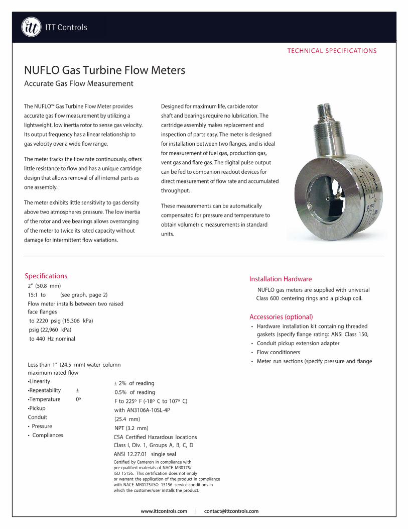
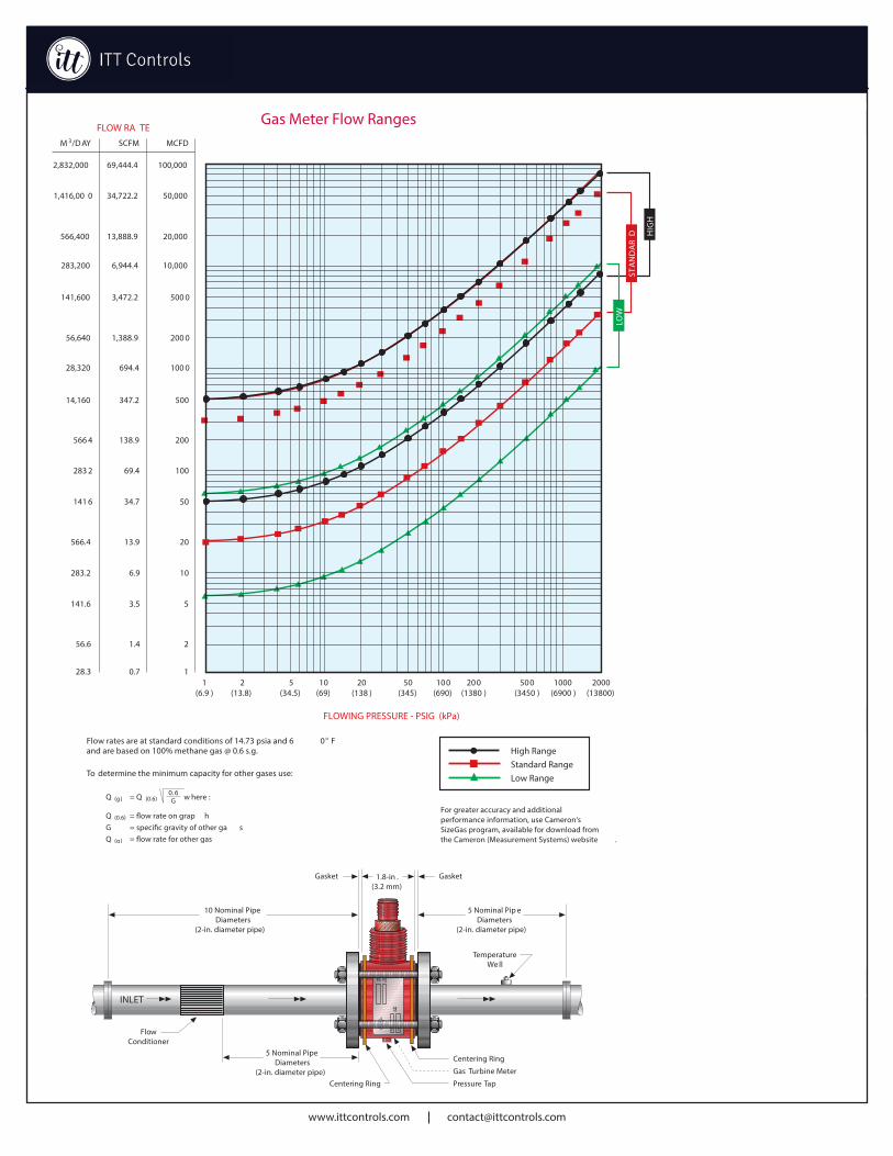
TECHNICAL SPECIFICATIONS NUFLO Gas Turbine Flow Meters Accurate Gas Flow Measurement The NUFLO™ Gas Turbine Flow Meter provides accurate gas flow measurement by utilizing a lightweight, low inertia rotor to sense gas velocity. Its output frequency has a linear relationship to gas velocity over a wide flow range. The meter tracks the flow rate continuously, offers little resistance to flow and has a unique cartridge design that allows removal of all internal parts as one assembly. The meter exhibits little sensitivity to gas density above two atmospheres pressure. The low inertia of the rotor and vee bearings allows overranging of the meter to twice its rated capacity without damage for intermittent flow variations. Designed for maximum life, carbide rotor shaft and bearings require no lubrication. The cartridge assembly makes replacement and inspection of parts easy. The meter is designed for installation between two flanges, and is ideal for measurement of fuel gas, production gas, vent gas and flare gas. The digital pulse output can be fed to companion readout devices for direct measurement of flow rate and accumulated throughput. These measurements can be automatically compensated for pressure and temperature to obtain volumetric measurements in standard units. Installation Hardware NUFLO gas meters are supplied with universal Class 600 centering rings and a pickup coil. Accessories (optional) • Hardware installation kit containing threaded gaskets (specify flange rating: ANSI Class 150, • Conduit pickup extension adapter • Flow conditioners Meter run sections (specify pressure and flange Specifications 2” (50.8 mm) to 15:1 (see graph, page 2) Flow meter installs between two raised face flanges to 2220 psig (15,306 kPa) psig (22,960 kPa) to 440 Hz nominal Less than 1” (24.5 mm) water column maximum rated flow •Linearity ± 2% of reading •Repeatability ± 0.5% of reading •Temperature F to 225º F (-18º C to 107º C) •Pickup with AN3106A-10SL-4P Conduit (25.4 mm) • Pressure NPT (3.2 mm) • Compliances CSA Certified Hazardous locations Class I, Div. 1, Groups A, B, C, D ANSI 12.27.01 single seal Certified by Cameron in compliance with pre-qualified materials of NACE MR0175/ ISO 15156. This certification does not imply or warrant the application of the product in compliance with NACE MR0175/ISO 15156 service conditions in which the customer/user installs the product. www.ittcontrols.com [email protected] www.ittcontrols.com [email protected]
Transcript

TECHNICAL SPECIFICATIONS

NUFLO Gas Turbine Flow MetersAccurate Gas Flow Measurement

The NUFLO™ Gas Turbine Flow Meter provides

accurate gas flow measurement by utilizing a

lightweight, low inertia rotor to sense gas velocity.

Its output frequency has a linear relationship to

gas velocity over a wide flow range.

The meter tracks the flow rate continuously, o�ers

little resistance to flow and has a unique cartridge

design that allows removal of all internal parts as

one assembly.

The meter exhibits little sensitivity to gas density

above two atmospheres pressure. The low inertia

of the rotor and vee bearings allows overranging

of the meter to twice its rated capacity without

damage for intermittent flow variations.

Designed for maximum life, carbide rotor

shaft and bearings require no lubrication. The

cartridge assembly makes replacement and

inspection of parts easy. The meter is designed

for installation between two flanges, and is ideal

for measurement of fuel gas, production gas,

vent gas and flare gas. The digital pulse output

can be fed to companion readout devices for

direct measurement of flow rate and accumulated

throughput.

These measurements can be automatically

compensated for pressure and temperature to

obtain volumetric measurements in standard

units.

Installation Hardware NUFLO gas meters are supplied with universal

Class 600 centering rings and a pickup coil.

Accessories (optional)• Hardware installation kit containing threaded

gaskets (specify �ange rating: ANSI Class 150,

• Conduit pickup extension adapter• Flow conditioners• Meter run sections (specify pressure and �ange

Specifications2” (50.8 mm)

to 15:1 (see graph, page 2) Flow meter installs between two raised face �anges to 2220 psig (15,306 kPa) psig (22,960 kPa) to 440 Hz nominal

Less than 1” (24.5 mm) water columnmaximum rated �ow•Linearity ± 2% of reading•Repeatability ± 0.5% of reading•Temperature 0º F to 225º F (-18º C to 107º C)•Pickup with AN3106A-10SL-4PConduit (25.4 mm)• Pressure NPT (3.2 mm)• Compliances CSA Certi�ed Hazardous locations

Class I, Div. 1, Groups A, B, C, DANSI 12.27.01 single seal Certi�ed by Cameron in compliance with pre-quali�ed materials of NACE MR0175/ ISO 15156. This certi�cation does not imply or warrant the application of the product in compliance with NACE MR0175/ISO 15156 service conditions in which the customer/user installs the product.

www.ittcontrols.com [email protected] [email protected]

L O C AT I O N S

North and South America14450 JFK Blvd.Houston, TX 77032USATel [email protected]

Europe, Africa, Caspian and Russia3 Steyning WaySouthern Cross Trading EstateBognor RegisWest Sussex PO22 9TTEngland, UKTel [email protected]

Asia Pacific Suite 16.02 Menara Am FrstNo. 1 Jalan 19/346300 Petaling JayaSelangor Darul EhsanMalaysiaTel [email protected]

Middle EastLevel 9, Al Jazira Club Tower AP.O. Box 47280, Muroor RoadAbu Dhabi United Arab EmiratesTel [email protected]

OT H E R L O C AT I O N S

A L G E R I A

C A N A DA

C H I N A

I N D I A

M A L AYS I A

R U SS I A

UA E

U K

U S A

www.c-a-m.com/measurement

FLOW RA TE

FLOWING PRESSURE - PSIG (kPa)

To determine the minimum capacity for other gases use:

Q (g ) = Q (0.6) w here :

Q (0.6) = flow rate on grap hG = specific gravity of other ga sQ (g ) = flow rate for other gas

0. 6G

Gas Meter Flow Rate

SCFM

69,444.4

34,722.2

13,888.9

6,944.4

3,472.2

1,388.9

694.4

347.2

138.9

69.4

34.7

13.9

6.9

3.5

1.4

0.7

100,000

50,000

20,000

10,000

500 0

200 0

100 0

500

200

100

50

20

10

5

2

1

MCFDM 3/D AY

2,832,000

1,416,00 0

566,400

283,200

141,600

56,640

28,320

14,160

566 4

283 2

141 6

566.4

283.2

141.6

56.6

28.31

(6.9 )2

(13.8)5

(34.5)10

(69)20

(138 )50

(345)100

(690)200

(1380 )500

(3450 )1000

(6900 )2000

(13800)

LOW

STA

ND

AR

D HIG

H

For greater accuracy and additional performance information, use Cameron's SizeGas program, available for download from the Cameron (Measurement Systems) website .

Flow rates are at standard conditions of 14.73 psia and 6 0° F and are based on 100% methane gas @ 0.6 s.g. High Range

Standard RangeLow Range

Gas Meter Flow Ranges

10 Nominal PipeDiameters

(2-in. diameter pipe)

5 Nominal Pip eDiameters

(2-in. diameter pipe)

5 Nominal PipeDiameters

(2-in. diameter pipe)

FlowConditioner

TemperatureWe ll

1.8-in .(3.2 mm)

INLET

GasketGasket

Gas Turbine Meter

Pressure TapCentering Ring

Centering Ring

www.ittcontrols.com [email protected]


Recommended