126
CASE NUMBER:
| Date post: | 03-Dec-2018 |
| Category: |
Documents |
| Upload: | nguyendien |
| View: | 226 times |
| Download: | 0 times |
CASE NUMBER:
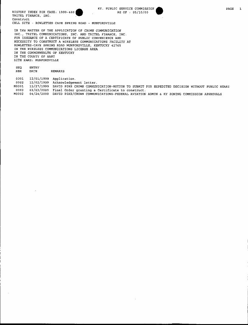
a KY. PUBLIC SERVICE COMMISSION HISTORY INDEX FOR CASE: 1999-480 AS OF : OS/lO/OO TRITEL FINANCE, INC. Construct CELL SITE - ROWLETTES CAVE SPRING ROAD - MUNFORDVILLE
PAGE 1
IN THE MATTER OF THE APPLICATION OF CROWN COMMUNICATION INC., TRITEL COMMUNICATIONS, INC. AND TRITEL FINANCE, INC. FOR ISSUANCE OF A CERTIFICATE OF PUBLIC CONVENIENCE AND NECESSITY TO CONSTRUCT A WIRELESS COMMUNICATIONS FACILITY AT ROWLETTES-CAVE SPRING ROAD MUNFORDVILLE, KENTUCKY 42765 IN THE WIRELESS COMMUNICATIONS LICENSE AREA IN THE COMMONWEALTH OF KENTUCKY IN THE COUNTY OF HART SITE NAME: MUNFORDVILLE
SEQ ENTRY NBR DATE REMARKS
0001 12/01/1999 Application. 0002 12/02/1999 Acknowledgement letter.
0003 03/03/2000 Final Order granting a Certificate to construct. MOO01 12/27/1999 DAVID PIKE CROWN COMMUNICATION-MOTION TO SUBMIT FOR EXPEDITED DECISION WITHOUT PUBLIC HEAR1
MOO02 04/24/2000 DAVID PIKE/CROWN COMMUNICATIONS-FEDERAL AVIATION ADMIN & KY ZONING COMMISSION APPROVALS
April 24, 2000
Susan G. Hutcherson Filings Division Manager, Docket Branch Kentucky Public Service Commission P.O. Box 615 Frankfort, KY 40602
Re: Applicant: Crown Communication, Inc. PSC Case No.: 99-480 Crown Site No.: 263-1 10 Crown Site Name: Munfordville Fed era I Aviation Administration A p p rova I Kentucky Airport Zoning Commission Approval
Dear Susan:
Please accept this letter and the attached documents as an official filing in the above- referenced Public Service Commission action. The Certificate of Public Convenience and Necessity issued in this action called for the Applicant to file a copy of the Federal Aviation Administration and Kentucky Airport Zoning Commission approvals once they were obtained. Copies of this relevant documentation are attached to this letter for inclusion in the official case file.
If you have any questions or comments concerning this matter, please do not hesitate to contact me.
Sincerely,
Regional Counsel, Crown Communication Inc. E-mail: [email protected]
DAP/sl b
Enclosures
Shepherdsville Office 200 S. Buckman Street P.O. Box 369 0 Shepherdsville, Kentiicky 40165-0369 (502) 955-4400 / Fax: (502) 543-4410
Frankfort Office Frankfort Plaza e P.O. Box 771 0 Frankfort, Kentucky 40602-0771 (502) 875-4048 I
r- I
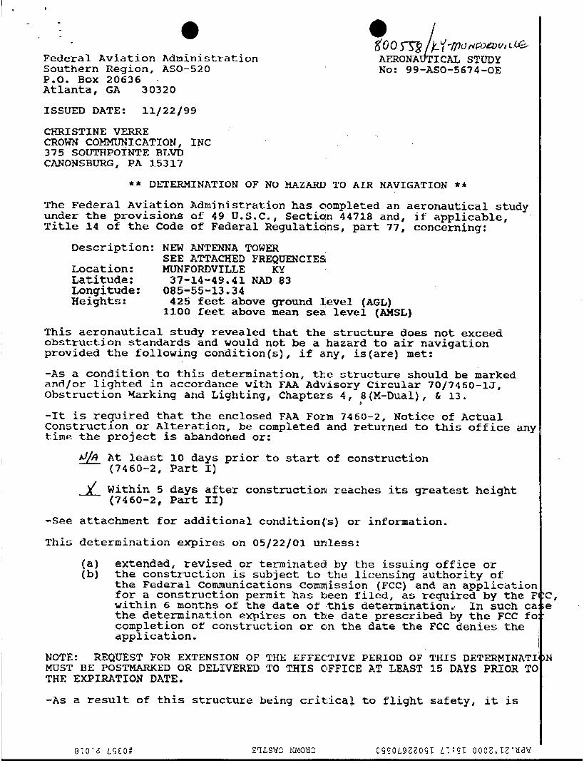
Federal Aviation Administration Southern Region, ASO-520
Atlanta, GA 30320
ISSUED DATE: 11/22/99
P-0. BOX 20636 .
CHRISTINE VERRE CROWN COMMUNICATION, 1:NC 3 7 5 SOUTHPOINTE BLVT) CANONSBURG, PA 35317
goo Ly-fllJNmav* L e , AERONA h ICAL STUDY NO: 99-ASO-5674-OE
** DETERMINATION OF NO HAZARD TO AIR NAVIGATION ** The Federal Aviation under the provisions Title 1 4 of the Code
Administration has completed an aeronautical study of 49 U . S . C . , Section 44718 and, if applicable, of Federal Regulatialns, part 77, concerning:
Description: NEW ANTENNA TOWER SEE ATTACHED FREQUENCIES,
LO ca t ion : MUNFORDVIUE KY Latitude : 37-14-49.41 NAD 83 Longitude: 085-55-13.34 Heights : 425 feet above ground 1,evel (AGL)
1100 feet above mean sea level (AMSL)
This aeronautical study revealed that the, structure does not exceed. obstruction standards and would not be a hazard to a i r navigation provided the following condition(s), if a,ny, is(are) m e t :
-As a condition to this determination, t h e structure should be marked and/or lighted in accordance with FAA Advisory Circular 70/7460-1J, Obst ruc t ion Yarking ahd Lighting, Chapters 4 , 8 (K-Dual) , & 13.
-It is required t h a t the enclosed FAA Form 7460-2, Notice of Actual Construction or Alteration, be completed and returned to this office any time the project is abandoned or:
D
.'/o A t least 10 days prior t o start of construction (7460-2, Part I)
Within 5 days after construct ion reaches its greatest height (7460-2, Part 11)
-See attachment for additional condition('s) or information.
This determination expires on 05/22/01 unless:
(a) extended, revised or terminated by t h e issuing office or (b) the construction is subject to the licensing authority of
the Federal Communications Cornmission (FCC) and an applicatior for a construction permit has been filed, as required by the E within 6 months of the date o f this determination., In such cz the determination expires on th.e date prescribed by t h e FCC fc completion of construction or on the date the FCC dehies the application.
NOTE: REQUEST FOR EXTENSION OF THE EFFECTIVE PERIOD OF THIS DETPERMINATI
THE EXPTRATION DATE. MUST BE POSTMARKED OR DELIVERED TO THIS OFFICE AT LEAST 15 DAYS PRIOR TC
-As a result of t h i s s t r u c t u r e being c r i t i c a l to flight safety, it is
c , e
N

- 0 0 required that the . A be kept apprised as to the status of this project. this determination.
Failure t c r respond to periodic FAA inquiries could invalidate
This determination is based, in part, on the foregoing description whic includes specific coordinates, heights, f revency( i e s ) and power. m y changes in coordinates, heights, frequeqcy(1es) or use of greater powel will void this determination. including increase in heights, power, or the addition of other transmitters, requires separate hotice t,o the FAA.
This determination does include temporary construction equipment such z cranes, derricks, etc., which may be use'd during actual construction of the structure. However, this equipbnant shall not exceed the overall heights as indicated above. Equipment which has a height greater than s t u d i e d structure requires separate notice to the FAA.
This determination concerns the effect oif this structure on the safe ax efficient use of navigable airspace by a,ircraft and does not relieve tl sponsor of compliance responsibxlities r'elating to any l a w , ordinance, regulation of any Federal, State, or locial government body.
A copy of this determination will be forwarded to the Federal Comunici commission if the structure is subject t 'o their licensing authority.
If we can be of further assistance, please contact our office at 404-305-5581, please refer to Aeronautical Study N u m b e r 99-ASO-5674-OE.
Any future construction or alteration,
On any future correspondence concerning this matter,
ade Carpentfer ..
Specialiit, Airspace Branch
7460-2 Attached Attachment
he
r
ions

AERONAUTICAL STUDY NO. 99-ASO-5 674-OE
FREQUENCIES
33-54 MHZ 72-73 MH2 144-162 MI.iz 220-222 MHX 450-502 MHz 800-960 MHZ 1,500 lk%
5,0004,500 M H z 10,000-1 1,000 MHz 18,000 AdHz 2 I,OOb MHz 24,000 MHZ 38,000 MHZ
1,900-2,oOO MHz
2-18 GHIz
100 Watts 100 watts 250 Watts 100 Watts 250 watts 500 Watr 500 Watts SO0 Watts 100 watts 100 watts 100 waas 100 watts IOoW& 100 watts
80 dbm EIRP
125 ]8[olma Street fix (502) 564-7953
Frankfort, DKY 40622 NO.: -0-GLW-99-275 0
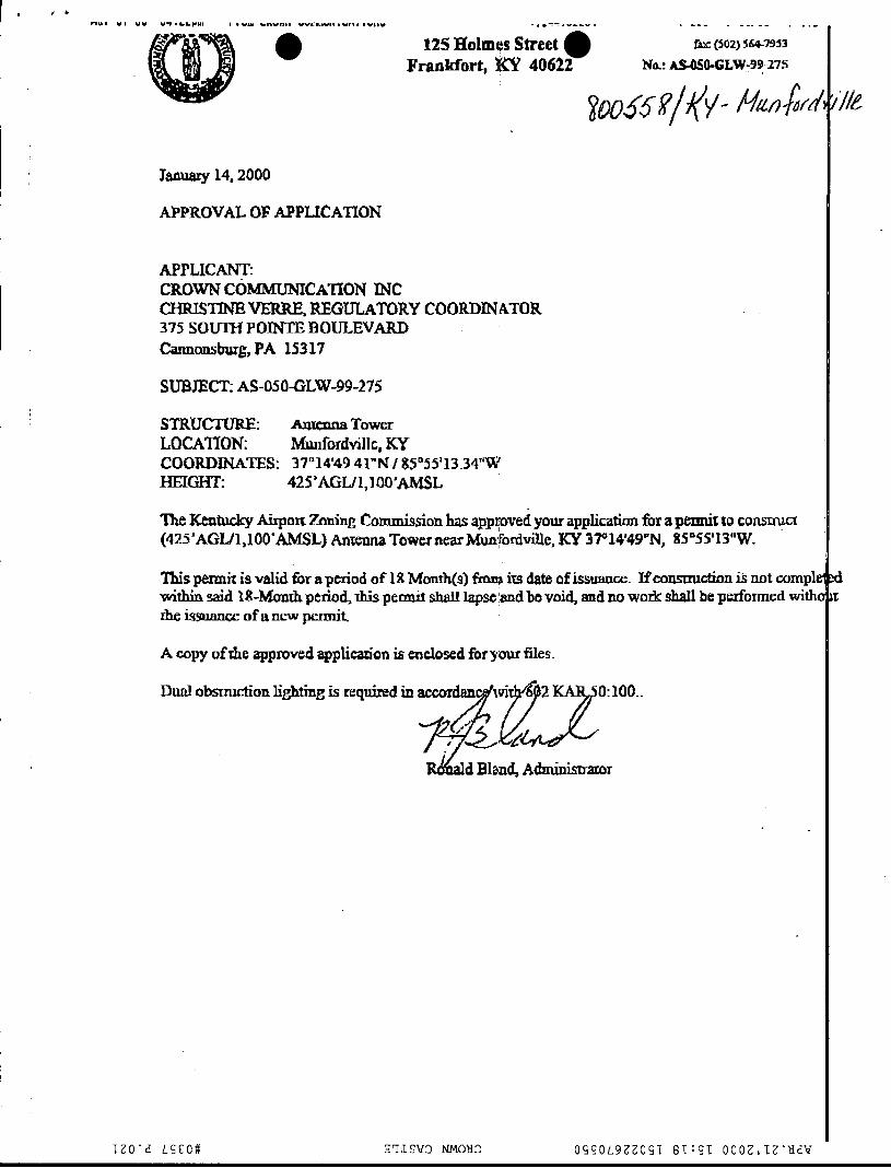
Jaauary 14,2000
APPROVAL OF APPLICATION
APPLICANT: CROWN COMMUNIcAmON WC C I - T r r r S W VERRE, REGULATORY COORDINATOR 375 SOUTH P O N E BOULEVARD Ckmnonsbwg, PA 153 17
SUBJECT; AS-0504LW-99-275
STRUCl7JR.E: Amenna Tower LOCATION: Munfordvillc, Icy COORDINATES: 37" 14'49Al"N / 85 '55'13.34"w mm: 42YAGW1,l OO'AMSL
ne mtucky *on Zmhg Commission has appipved your application for a pennix to c o m w (425'AGUl,lOO'AMSL) Anmna Tower near Munkbrdvdle, KY 37°14'49"N, 85"55'13"W.
ms permit is valid tbr a period of 1% Manth(s) fhnj irs dab of issuance. Hcoarrmction is not comph within said ZB-Manrh period, rhis permit shatz lapst'md be void, and no wndc shall be performed with( rhe issuance of a new permit
A mpy ofrhe approved applicaa'on is enclosed for your files.
Dual obsrmction lighting is required in a c c pz: 100..
.

COMMONWEALTH OF KENTUCKY PUBLIC SERVICE COMMISSION
21 1 SOWER BOULEVARD POST OFFICE BOX 61 5
FRANKFORT, KY. 40602 (502) 564-3940
CERTIFICATE OF SERVICE
RE: Case No. 1999-480 TRITEL FINANCE, INC.
I, Stephanie Bell, Secretary of the Public Service Commission, hereby certify that the enclosed attested copy of the Commission’s Order in the above case was served upon the following by U.S. Mail on March 3, 2000.
See attached parties of record.
Secretary of thFCommissiofY
SB/hv Enclosure

/
David Burak Tritel Finance, Inc. 1512 Crums Lane Louisville, KY. 40216
Lloyd McCarthy Crown Communication Inc. Commonwealth Business Center 11001 Bluegrass Parkway, Suite 330 Louisville, KY. 40299
Honorable David A. Pike Attorney for Crown Communication Inc Pike Legal Group 200 South Buckman Street P. 0. Box 369 Shepherdsville , ICY. 40165 0369
Honorable Sandra F. Keene & Honorable Mark W. Dobbins Attorneys for Tritel Tilford, Dobbins, Alexander,
One Riverfront Plaza, Suite 1400 Louisville, KY. 40202
Buckaway & Black

r.,
In the Matter of:
COMMONWEALTH OF KENTUCKY
BEFORE THE PUBLIC SERVICE COMMISSION
APPLICATION OF CROWN COMMUNICATION INC., TRITEL COMMUNICATIONS, INC. AND TRITEL FINANCE, INC. FOR ISSUANCE OF A CERTIFICATE OF PUBLIC CONVENIENCE AND NECESSITY TO CONSTRUCT A WIRELESS
CAVE SPRING ROAD, MUNFORDVILLE, KENTUCKY 42765 IN THE WIRELESS COMMUNICATIONS LICENSE AREA IN THE COMMONWEALTH OF KENTUCKY IN THE COUNTY OF HART SITE NAME: MUNFORDVILLE
C 0 M M U N I CAT1 0 N S FAC I L ITY AT RO WL ETTE S-
SITE NUMBER: 263-1 10
O R D E R
On December 1, 1999, Crown Communication Inc. ("Crown") and Tritel
Communication, Inc. (collectively, the "Applicants") filed an application seeking a Certificate
of Public Convenience and Necessity to construct and operate a wireless
telecommunications facility. Crown has requested authorization to construct a cell site in
Hart County and Tritel has provided evidence that the public convenience and necessity
will be served by the proposed construction.
The proposed facility consists of a guyed antenna tower not to exceed 250 feet in
height, to be located at Rowlettes-Cave Spring Road, Munfordville, Hart County, Kentucky.
The coordinates for the proposed facility are North Latitude 37" 14' 49.41" by West
Lonaitude 85" 55' 13.34".

Crown has provided information regarding the structure of the tower, safety
Based upon the measures, and antenna design criteria for the proposed facility.
application, the design of the tower and foundation conforms to applicable nationally
recognized building standards, and the plans have been certified by a Registered
Professional Engineer.
Pursuant to 807 KAR 5063, the Applicants have notified the Hart County/Judge
Executive of the proposed construction. The Applicants have filed applications with the
Federal Aviation Administration ("FAA") and the Kentucky Airport Zoning Commission
("KAZC") seeking approval for the construction and operation of the proposed facility. Both
applications are pending.
The Applicants have filed evidence of the appropriate notices provided pursuant to
807 KAR 5063. The notices solicited any comments and informed the recipients of their
right to request intervention. To date, no requests for intervention have been filed with the
Commission.
Pursuant to KRS 278.280, the Commission is required to determine proper
practices to be observed when it finds, upon complaint or on its own motion, that the
facilities of any utility subject to its jurisdiction are unreasonable, unsafe, improper, or
insufficient. To assist the Commission in its efforts to comply with this mandate, Crown
should notify the Commission if it does not use this antenna tower to provide service in the
manner set out in its application and this Order. Upon receipt of such notice, the
Commission may, on its own' motion, institute proceedings to consider the proper practices,
including removal of the unused antenna tower, which should be observed by Crown.
-
-2-

The Commission, having considered the evidence of record and being otherwise
sufficiently advised, finds that the Applicants have demonstrated that a facility is necessary
to provide adequate utility service and therefore should be granted a Certificate of Public
Convenience and Necessity to construct the proposed facility.
I
IT IS THEREFORE ORDERED that:
1. Crown is granted a Certificate of Public Convenience and Necessity to
construct a guyed antenna tower not to exceed 250 feet in height, with attached antennas,
to be located at Rowlettes-Cave Spring Road, Munfordville, Hart County, Kentucky. The
coordinates for the proposed facility are North Latitude 37" 14' 49.41" by West Longitude
85" 55' 13.34".
2. The Applicants shall file a copy of the final decisions regarding their pending
FAA and KAZC applications for the proposed construction within 10 days of receiving these
decisions.
3. Crown shall immediately notify the Commission in writing, if, after the
antenna tower is built and utility service is commenced, the tower is not used for a period
of 3 months in the manner authorized by this Order.
Done at Frankfort, Kentucky, this 3rd day of Wch, 2000. -
By the Commission
ATTEST:
p?j*Tr Executive Director

. . e I
COMMONWEALTH OF KENTUCKY RECEIVED BEFORE THE PUBLIC SERVICE COMMISSION
DEC 2 7 1999 In the Matter of:
APPLICATION OF CROWN COMMUNICATION INC.
PUbLlC SERVICE coMMlssloN
) TRITEL COMMUNICATIONS, INC. AND TRITEL j FINANCE, INC. FOR ISSUANCE OF A CERTIFICATE OF PUBLIC CONVENIENCE AND NECESSITY TO CONSTRUCT ) CASE NO.: 99480 A WIRELESS COMMUNICATIONS FACILITY AT ROWLETTES-CAVE SPRING ROAD, MUNFORDVILLE, KY 42765) IN THE WIRELESS COMMUNICATIONS LICENSE AREA IN THE COMMONWEALTH OF KENTUCKY IN THE COUNTY OF HART
SITE NAME: MUNFORDVILLE
) ) )
SITE NUMBER: 263-1 10
* * * * * * *
MOTION TO SUBMIT FOR EXPEDITED DECISION WITHOUT PUBLIC HEARING
(NO INTERVENERS)
Come the Crown Communication Inc. (“Crown”), as ultimate owner, and Tritel
Communications, Inc. and Tritel Finance, Inc. (both Tritel entities jointly referred to as
“Provider”), as a licensed public utility in the Commonwealth of Kentucky, all three entities
hereinafter jointly referred to as “Applicants”, by counsel, and move the Kentucky Public
Service Commission (“PSC”) to promptly grant a Certificate of Public Convenience and
Necessity (‘CPCN”) in the within Application proceeding based on the following facts and
circumstances:
1. The Applicants have met all filing requirements under the Kentucky Revised
Statutes and the Kentucky Administrative Regulations applicable to this proceeding.
2. There are no Interveners in this proceeding after Notice has been afforded
I pursuant to the terms of the Kentucky Revised Statutes and the Kentucky Administrative
.Regulations.
3. The Wireless Communications Facility (“WCF”) which is the subject of this
Application for a CPCN is a vital element of the Provider‘s wireless communications
network, and is necessary to provide service in accordance with provisions of its license
with the Federal Communications Commission.
4. The county where the WCF is located has not registered for the right to
regulate cell cites with the PSC, and has not adopted planning and zoning regulations in
accordance with KRS 100.
5. The Application in this administrative proceeding was originally filed with the
PSC on December 1, 1999, 26 days before the submission of this Motion.
WHEREFORE, Crown and the Provider, Applicants herein, by counsel, urge the
PSC to promptly grant a CPCN in accordance with the terms of the Application in this
proceeding without public hearing on an expedited basis.
Respectfully submitted,
Pike Legal Group 200 S. Buckman Street Post Office Box 369 Shepherdsville, KY 401 65-0369 Telephone: (502) 955-4400
E-Mail: ATTORNEY FOR CROWN COMMUNICATION INC.
Telefax: (502) 543-441 0 pi keleg al @ aol . com
and
I , , . - s
Mark W. Dobbins Sandra F. Keene Tilford, Dobbins, Alexander, Buckaway, & Black Suite 1400 One Riverfront Plaza Louisville, KY 40202 Telephone: (502) 584-61 37 ATTORNEYS FOR TRITEL COMMUNICATIONS, INC. & TRITEL FINANCE, INC.
SB/sh Enclosure
a
C O M M O N W E A L T H OF KENTUCKY PUBLIC SERVICE COMMISSION
7 3 0 SCHENKEL LANE POST OFFICE BOX 61 5
FRANKFORT, KY. 40602 (502) 564-3940
December 10, 1999
To: All parties of record
RE: Case No. 1 9 9 9 - 4 8 0 TRITEL FINANCE, INC.
The Commission staff ‘has reviewed your application in the above case and finds that it meets the minimum filing require- ments. Enclosed please find a stamped filed copy of the first page of your filing. processed as expeditiously as possible.
at 5 0 2 / 5 6 4 - 3 9 4 0 .
This case has been docketed and will be
If you need further assistance, please contact my staff
Sincerely, m**w Stephanie Bell Secretary of the Commission

,
David Burak Tritel Finance, Inc. 1512 Crums Lane Louisville, KY. 40216
Lloyd McCarthy Crown Communication Inc. Commonwealth Business Center 11001 Bluegrass Parkway, Suite 330 Louisville. KY. 40299
Honorable David A. Pike Attorney for Crown Communication InC Pike Legal Group 200 South Buckman Street P. 0. Box 369 Shepherdsville , KY. 40165 0369
Honorable Sandra F. Keene & Honorable Mark W. Dobbins Attorneys for Tritel Tilford, Dobbins, Alexander,
One Riverfront Plaza, Suite 1400 Louisville, KY. 40202
Buckaway & Black

I
I
F I L E D COMMONWEALTH OF KENTUCKY
BEFORE THE PUBLIC SERVICE COMMISSION
In the Matter of:
APPLICATION OF CROWN COMMUNICATION INC., TRITEL COMMUNICATIONS, INC. AND TRITEL
) )
DEC - 11999 PUBLIC SERVICE
COMMISSION FINANCE, INC. FOR ISSUANCE OF A CERTIFICATE OF ) CASE NO.: 99-480 PUBLIC CONVENIENCE AND NECESSITY TO 1 CONSTRUCT A WIRELESS COMMUNICATIONS 1 FACILITY AT ROWLETTES-CAVE SPRING ROAD ) MUNFORDVILLE, KENTUCKY 42765 ) IN THE WIRELESS COMMUNICATIONS LICENSE AREA ) IN THE COMMONWEALTH OF KENTUCKY 1 IN THE COUNTY OF HART )
SITE NAME: MUNFORDVILLE SITE NUMBER: 263-1 10
* * * * * * *
Crown Communication Inc. ("Crown"), as ultimate owner, and Tritel
Communications, Inc. and Tritel Finance, Inc. (both Tritel entities jointly referred to as
"Provider" ), as a licensed public utility in the Commonwealth of Kentucky, hereinafter jointly
referred to as "Applicants", by counsel, pursuant to ( i ) KRS 278.020 and the rules and
regulations applicable thereto, and (ii) the Telecommunications Act of 1996, respectfully
submit their Application for a Certificate of Public Convenience and Necessity ("CPCN")
from the Public Service Commission of Kentucky ("PSC") to construct, maintain, and
operate a Wireless Communications Facility ("WCF") to serve the customers of the
Provider with wireless telecommunications services, and other wireless service provider
collocations in the area described herein.
,:
In support of this Application, the Applicants respectfully provide and state the
2
COMMONWEALTH OF KENTUCKY PUBLIC SERVICE COMMISSION
730 SCHENKEL LANE POST OFFICE BOX 61 5
FRANKFORT, KY. 40602 (502) 564-3940
December 2 , 1999
To: All parties of record
RE: Case No. 1999-480 TRITEL FINANCE, INC. (Construct) CELL SITE - ROWLETTES CAVE SPRING ROAD - MUNFORDVILLE
This letter is to acknowledge receipt of initial application in the above case. December 1, 1999 and has been assigned Case No. 1999-480. In all future correspondence or filings in connection with this case, please reference the above case number.
The application was date-stamped received
If you need further assistance, please contact my staff at 502/564-3940.
Stephanie Bell Secretary of the Commission
SB/] c
I ' David Burak Tritel Finance, InC. 1512 Crums Lane Louisville, KY. 40216
Lloyd McCarthy Crown Communication Inc. Commonwealth Business Center 11001 Bluegrass Parkway, Suite 330 Louisville, KY. 40299
Honorable David A . Pike Attorney for Crown Communication InC Pike Legal Group I
200 South Buckman Street P. 0. Box 369 Shepherdsville , KY. 40165 0369 ,
Honorable Sandra F. Keene & Honorable Mark W. Dobbins Attorneys for Tritel Tilford, Dobbins, Alexander,
One Riverfront Plaza, Suite 1400 Louisville, KY. 40202
Buckaway & Black
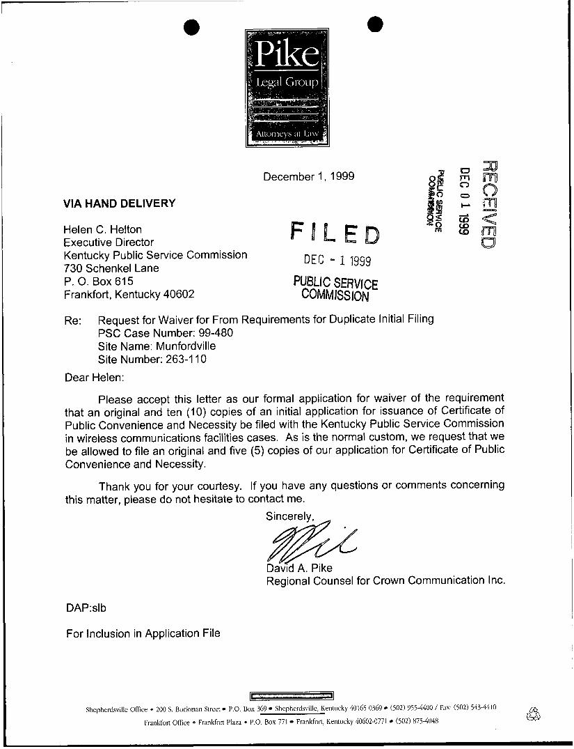
December 1, 1999
VIA HAND DELIVERY
Helen C. Helton Executive Director Kentucky Public Service Commission 730 Schenkel Lane DEC - 11999 P. 0. Box 615 PUBLIC SERVICE Frankfort, Kentucky 40602 COMMISSlON
Re: Request for Waiver for From Requirements for Duplicate Initial Filing PSC Case Number: 99-480 Site Name: Munfordville Site Number: 263-1 10
Dear Helen:
Please accept this letter as our formal application for waiver of the requirement that an original and ten ( I O ) copies of an initial application for issuance of Certificate of Public Convenience and Necessity be filed with the Kentucky Public Service Commission in wireless communications facilities cases. As is the normal custom, we request that we be allowed to file an original and five (5) copies of our application for Certificate of Public Convenience and Necessity.
Thank you for your courtesy. If you have any questions or comments concerning this matter, please do not hesitate to contact me.
Regional Counsel for Crown Communication Inc.
DAP:slb
For Inclusion in Application File
Shepherdsville Office 0 200 S Buckman Street 1’ 0 Box 369 Shepherdsvllle, Kentucky 40165-0369 (502) 955-4400 / Fax (502) 543-4410
Frankfort Office 0 Frankfort Plaza * P 0 Box 771 Frankfort, Kentucky 40602-0771 (502) 875-4048
ll COMMONWEALTH OF KENTUCKY
BEFORE THE PUBLIC SERVICE COMMISSION
In the Matter of: DEC - f 1999
APPLICATION OF CROWN COMMUNICATION INC., TRITEL COMMUNICATIONS, INC. AND TRITEL
) PUBLIC SERVICE CQMM ISS ION
FINANCE, INC. FOR lSSUANCE OF A CERTlFBCATE OF ) CASE NO.: 99480 PUBLIC CONVENIENCE AND NECESSITY TO ) CONSTRUCT A WIRELESS COMMUNICATIONS FACILITY AT ROWLETTES-CAVE SPRING ROAD ) MUNFORDVI LLE, KENTUCKY 42765 1 IN THE WIRELESS COMMUNICATIONS LICENSE AREA )
IN THE COUNTY OF HART 1
3 IN THE COMMONWEALTH OF KENTUCKY 1 % m
* E SITE NAME: MUNFORQVILLE - .< CQ
% m a
a
SITE NUMBER: 263-1 10
* * 4 4 4 * *
Crown Communication Inc. (“Crown”), as ultimate owner, and Britel
Communications, Inc. and Britel Finance, Inc. (both Trite1 entities jointly referred to as
“Provider“), as a licensed public utility in the Commonwealth of Kentucky, hereinafter jointly
referred to as “Applicants”, by counsel, pursuant to (i) KRS 278.020 and the rules and
regulations applicable thereto, and (ii) the Telecommunications Act of 1996, respectfully
submit their Application for a Certificate of Public Convenience and Necessity (“CPCN”)
from the Public Service Commission of Kentucky (“PSCm) to construct, maintain, and
operate a Wireless Communications Facility (“WCF”) to serve the customers of the
Provider with wireless telecommunications services, and other wireless service provider
collocations in the area described herein.
In support of this Application, the Applicants respectfully provide and state the
2

following information:
1. The complete names and addresses of the Applicants are:
Crown Communication Inc., a Delaware Corporation, 375 Southpointe Boulevard, Canonsburg, PA 15317, (724) 416-2000, having a local address of Commonwealth Business Center, 1 1001 Bluegrass Parkway, Suite 330, Louisville, Kentucky 40299, (502) 240-0044.
Tritel Communications, Inc., a Delaware Corporation, 141 0 Livingston Lane, Jackson, Mississippi 39213 (601) 362-2200, having a local address of 2351 Nelson Miller Parkway, Suite 103, Louisville, Kentucky 40223.
Tritel Finance, Inc., a Delaware Corporation, 141 0 Livingston Lane, Jackson, Mississippi 39213 (601) 362-2200, having a local address of 2351 Nelson Miller Parkway, Suite 103, Louisville, Kentucky 40223.
2. Crown constructs, owns, manages, maintains, and operates independent
communications networks. Crown owns and manages safe, clean, and well-maintained
facilities. Crown facilities do not generate smoke, odors, noise, noxious gases, vibrations,
or increase traffic. Studies show that Crown’s facilities will not pollute air, soil, or water,
nor will they adversely affect radio or television reception or transmission. A certified copy
of the Certificate of Authority issued by the Secretary of State of the Commonwealth of
Kentucky and a certified copy of the Articles of Incorporation issued by the Secretary of
State of Delaware for Crown are attached or described as part of Exhibit A.
3. After completion of the proposed WCF, Crown will lease or license space on
said tower and the surrounding site so that the Provider may locate and operate its facility
including all required antennas and appurtenances. The proposed WCF will serve an area
completely within the Provider’s Federal Communications Commission “FCC” licensed
3
r
service area in the Commonwealth of Kentucky. The Provider is authorized to provide
wireless services by the FCC and the PSC. In compliance with the PSC’s Order in
Administrative Case No. 370, Provider previously filed with the PSC its Notice of Intent to
Construct and Operate a Commercial Mobile Radio Service (“CMRS”) Transmission
System with the Commonwealth of Kentucky. Included with said Notice were copies of
Provider’s Articles of Incorporation and FCC license. Trite1 also has filed a Tariff with the
PSC (Tariff No. 60-0067). Crown has located the proposed site in a manner such that
other wireless communications service providers will desire to collocate on said tower, and
will endeavor to provide all necessary facilities to make collocation attractive to them.
4. The public convenience and necessity require the construction of the
proposed WCF. The construction of the WCF will bring the Provider’s services to an area
currently not served by the Provider and will thereby enhance the public’s access to
innovative and competitive wireless telecommunications services. The WCF will provide
a necessary link in the Provider’s telecommunications network that is designed to meet the
increasing demands for wireless services in Kentucky’s wireless communications licensed
area. The WCF is an integral link in the Provider’s network design that must be in place
to cover the proposed service area.
5. Crown’s construction of the described WCF is desirable because it allows
for the collocation of additional wireless service providers within this portion of the
Kentucky wireless communications licensed area. These services may include
telecommunications, wireless data transfer and Internet services, wireless cable, paging
systems, 91 I service, and other new products currently being developed in the wireless
4

industry. In addition, the WCF will be available for use by governmental agencies and
providers of emergency services. The WCF will provide a necessary link in Crown’s
wireless infrastructure network, and Crown, as part of its business structure, will diligently
pursue and encourage other wireless providers to collocate on the WCF. These services
will provide increased competition in the local Kentucky telecommunications market, which
will, in turn, promote competitive pricing, quality, and coverage options to users of
telecommunications services in this area. Crown’s vested interest in the collocation of
wireless service providers promotes the same goals for the local consumers.
6. The Applicants propose to construct a WCF at Rowtettes-Cave Spring Road,
Munfordville, Kentucky 42765 (37 14 49.41 North latitude, 85 55 13.34 West longitude),
in an area located entirely within the county referenced in the caption of this application.
The property on which the WCF will be located is owned by Mike K. Stinson. The
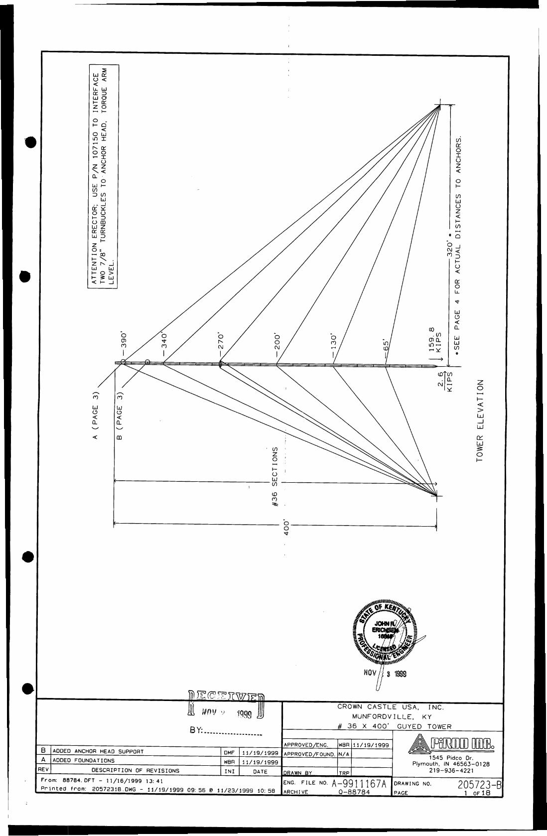
proposed WCF will consist of a 250-foot Guyed tower, with an approximately 20-foot
lightning arrestor attached at the top, for a total height of 270 feet. The WCF will also
include concrete foundations to accommodate the placement of the Provider’s proprietary
radio electronics equipment. The equipment will be housed in a prefabricated cabinet or
shelter that will contain: (i) the transmitting and receiving equipment required to connect
the WCF with the Provider’s users in Kentucky, (ii) telephone lines that will link the WCF
with the Provider’s other facilities, (iii) battery back-up that will allow the Provider to
operate even after a loss of outside power, and (iv) all other necessary appurtenances.
The Provider’s equipment cabinet or shelter will be approved for use in the
Commonwealth of Kentucky by the relevant building inspector. The WCF compound will
5

0 e be fenced and all access gate(s) will be secured. A description of the manner in which the
proposed WCF will be constructed is attached as Exhibit B and Exhibit C. Periodic
inspections will be performed on the WCF in accordance with the applicable regulations
or requirements of the PSC. The list of competing utilities, corporations, or persons is
attached as Exhibit D.
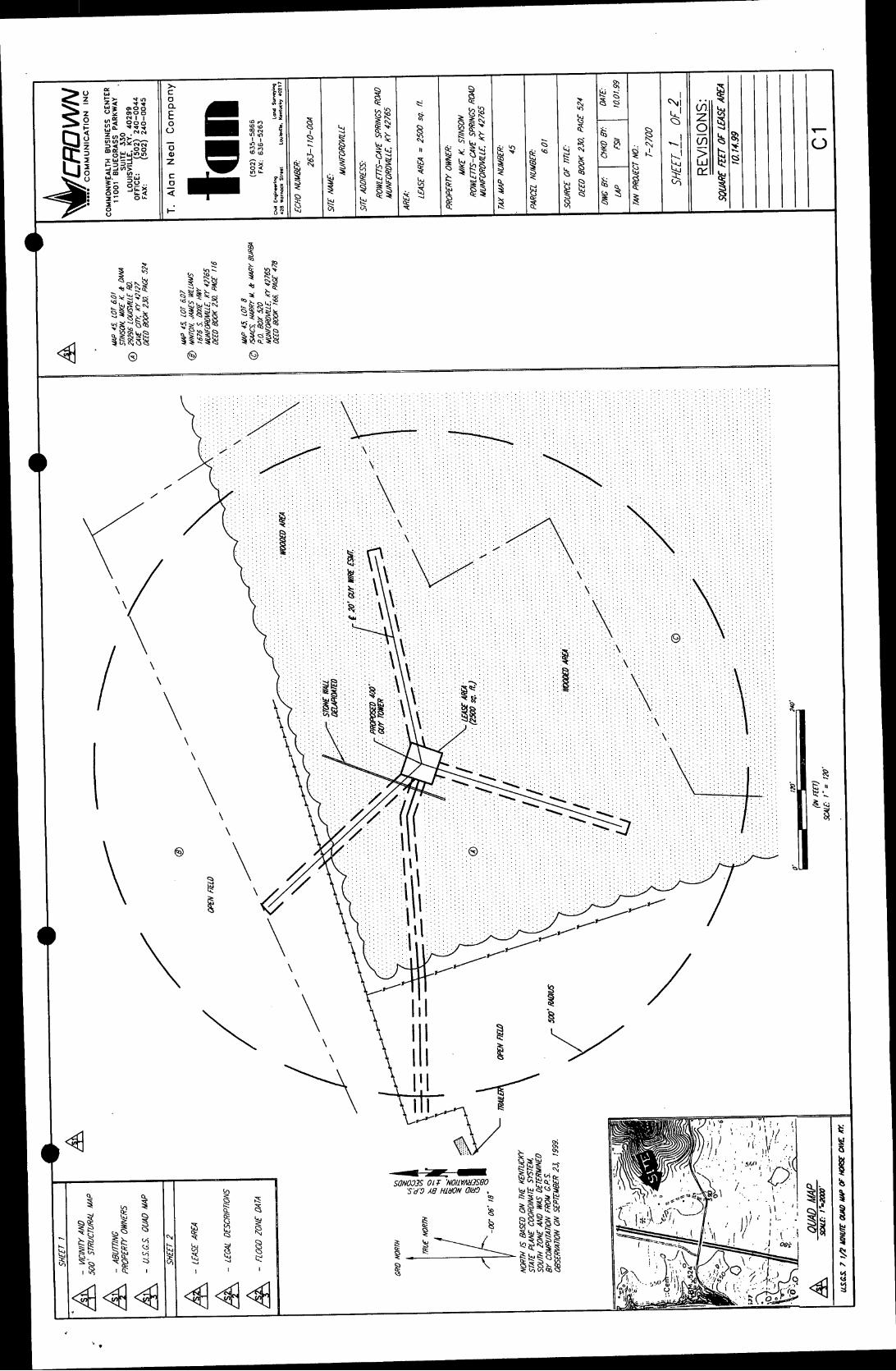
7. Reduced copies of the site development plan have been included as Exhibit
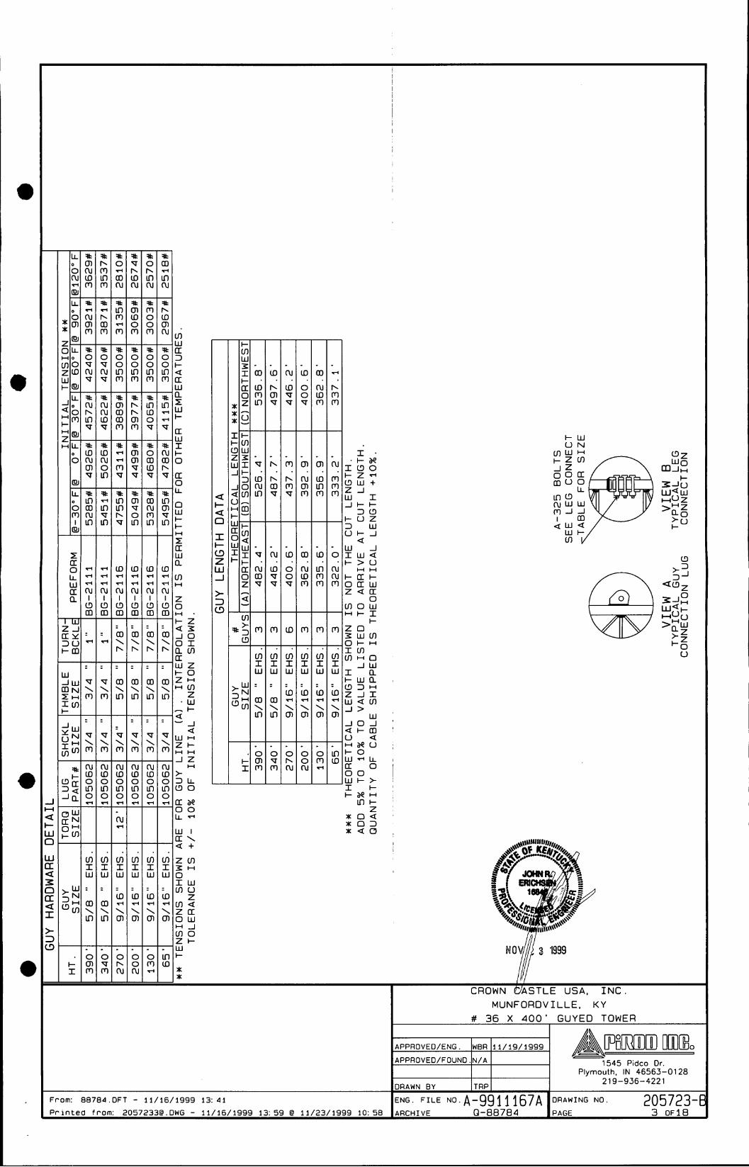
B and Exhibit C of this Application. A vertical profile sketch of the WCF signed and
sealed by a professional engineer registered in Kentucky depicting the tower height, as
well as a proposed configuration for the antennas of the Provider and future antenna
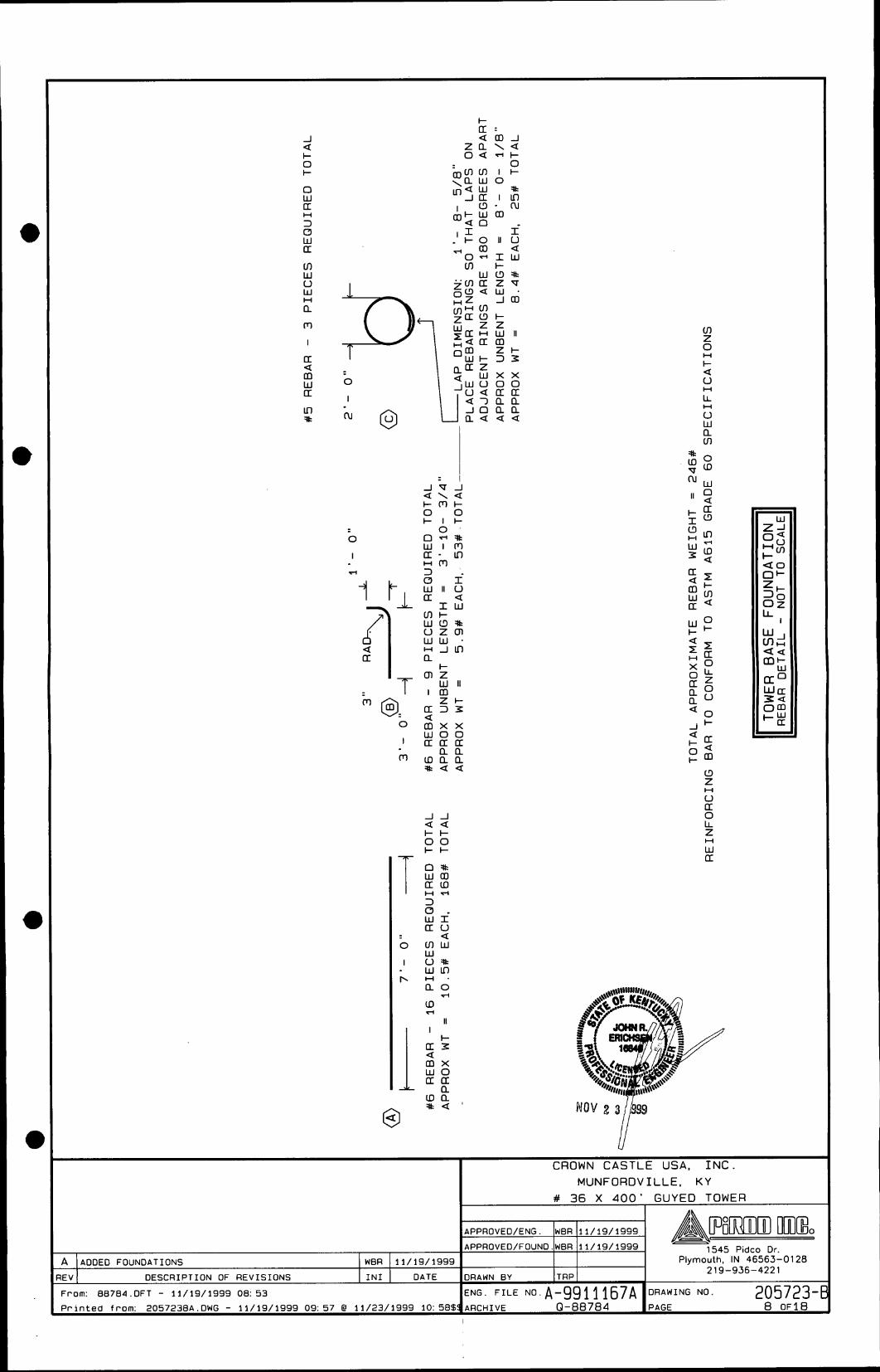
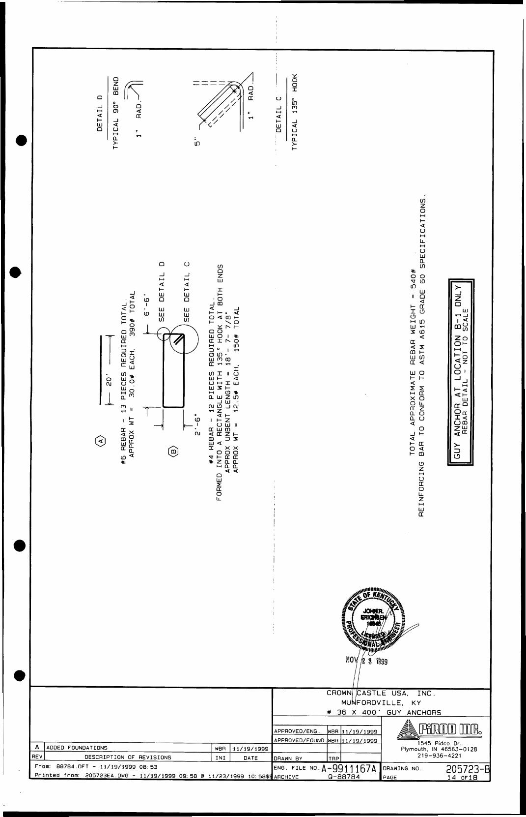
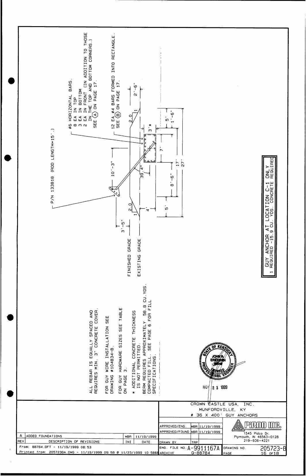
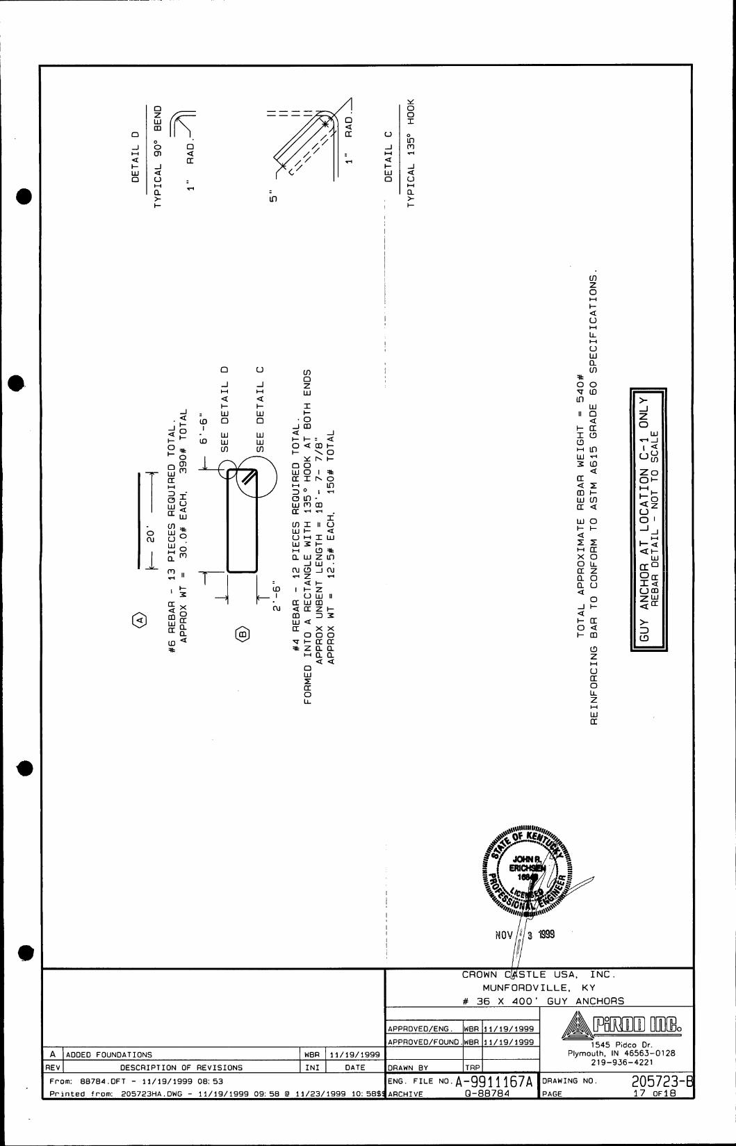
mounts, has also been included as part of Exhibit B. Foundation design plans and a
description of the standards according to which the tower was designed signed and sealed
by a professional engineer registered in Kentucky is included as part of Exhibit C.
8. The Applicants have considered the likely effects of the installation on
nearby land uses and values and have concluded that there is no more suitable location
reasonably available from which adequate services can be provided, and that there are
no reasonably available opportunities to collocate. The Applicants have attempted to
collocate on suitable existing structures such as a telecommunications towers or other
suitable structures capable of supporting the Provider’s facilities. No other suitable and
available collocation site was found to be located in the vicinity of the site. Information
regarding the Applicants’ efforts to achieve collocation in the vicinity are presented as
Exhibit E.
I
I
9. The Applicants have conducted a preliminary aeronautical evaluation for the
6
proposed WCF. The evaluation determined that the proposed structure height at this site
meets Federal Aviation Administration (‘‘FAA”) Regulation requirements. Furthermore,
FAA notice is required for the proposed construction, and lighting or marking requirements
may be applicable to this facility. A copy of the FAA Application is attached as Exhibit F.
Upon receiving authorization from the FAA, the Applicants will forward a copy of the
determination as a supplement to this Application proceeding.
I O . A copy of the Kentucky Airport Zoning Commission ( “ W C ” ) Application for
the proposed WCF is attached as Exhibit G. Upon receiving authorization from the KAZC,
the Applicants will forward a copy of the determination as a supplement to this Application
proceeding.
11. The WCF will be registered with the FCC pursuant to applicable federal
requirements. Appropriate required FCC signage will be posted on the site upon receipt
of the tower registration number.
12. A geotechnical-engineering firm has performed soil boring(s) and
subsequent geotechnical-engineering studies at the WCF site under the supervision of a
professional engineer registered in the Commonwealth of Kentucky who specializes in
geotechnical engineering, including subsurface exploration. The geotechnical-engineering
firm has performed many such studies for the communications industry. A copy of the
geotechnical-engineering report and evaluation signed and sealed by a professional
engineer registered in the Commonwealth of Kentucky who specializes in geotechnical
engineering, including subsurface exploration, is attached as Exhibit H. The name and
address of the geotechnical-engineering firm and the professional engineer registered in
7

r
the Commonwealth of Kentucky who supervised the examination of this WCF site are
included in Exhibit H.
13. Clear directions to the proposed WCF site from the County seat are attached
as Exhibit 1. The name and address of the preparer of Exhibit J is included in Exhibit J.
Crown, pursuant to a written agreement, has acquired the right to use the
WCF site and associated property rights. A copy of the abbreviated agreement recorded
with the County Clerk is attached as Exhibit J. Also included as part of Exhibit J is the
portion of the full agreement demonstrating that in the case of abandonment a method is
provided to dismantle and remove the cellular antenna tower, including a timetable for
removal.
14.
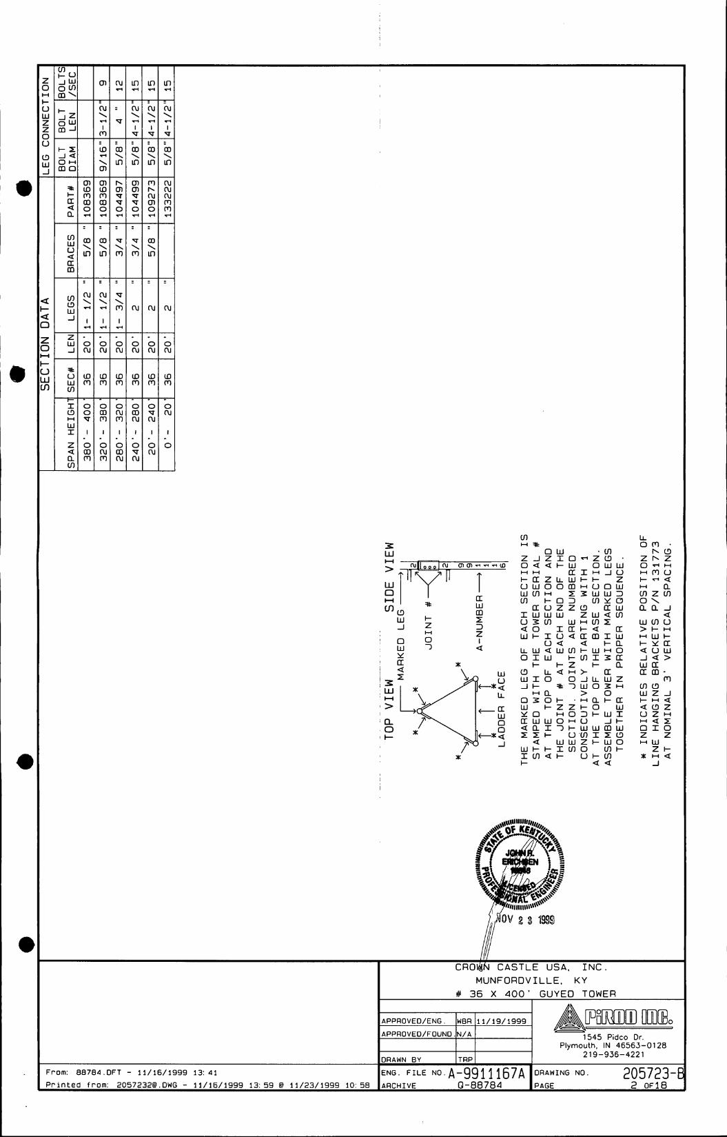
15. Personnel directly responsible for the design and construction of the
proposed WCF are well-qualified and experienced. Pirod (“the Tower Manufacturer”)
performed the tower and foundation design. The Tower Manufacturer is a nationally
recognized manufacturer and designer of communications towers. The Tower
Manufacturer has designed and installed communications towers throughout North
America. The Tower Manufacturer has assigned John Erichsen, a professional engineer
registered in the Commonwealth of Kentucky to design the WCF. This engineer
specializes in the design and engineering of guyed, self-support and monopole structures,
and has extensive experience in the design and construction of projects similar to the
Applicants’. These projects include the design of towers and the required foundations of
many other wireless facilities. All of the designs have been signed and sealed by John
Erichsen. The construction of the proposed WCF will be performed by Crown Network
a

Systems, an experienced, bonded, and insured erection company. The Tower Erection
Manager, Harold Harrington, will manage the tower erection. Harold Harrington is a tower
installation manager for Crown and has been erecting towers for the telecommunications
industry for over 8 years. All tower designs will meet or exceed applicable laws and
regulations.
16. Based on a review of Federal Emergency Management Agency Flood
Insurance Rate Maps, the registered land surveyor has noted in Exhibit B that the
proposed WCF is not located within any flood hazard area.
17. The possibility of high winds has been considered in the design of this tower.
The tower has been designed and engineered by professional engineers using computer
assistance and the same accepted codes and standards as are typically used for high-rise
building construction. The tower has been designed to withstand a wind loading of 70
m.p.h., using the Uniform Building Code of 1991 (“UBC-91”) and further modified by the
1993 Administrative Code. This tower has been designed in accordance with the
Electronic Industries Association (“EIA) 222-F Standards, which have been accepted and
approved by ANSI and is a nationally recognized tower design standard. Similarly, the
proposed WCF design has been developed with consideration of potential ground shaking
based on a negligible seismic zone of 1. Seismic loading is regarded as secondary to the
wind loading.
18. The site development plan signed and sealed by a professional engineer
registered in Kentucky was prepared by Charles E. Weiter, and was designed from a
survey performed by Jack L. Tarr. This site development plan is drawn to a scale of no
9
less than one (1) inch equals 200 feet, and identifies every owner of real estate within 500
feet of the proposed tower (according to the Property Valuation Administrator) and is
incorporated in the survey as part of Exhibit B. Every structure and every easement
within 500 feet of the proposed tower or within 200 feet of the access road including
intersection with the public street system is incorporated in the survey as part of Exhibit
B.
19. Crown, on behalf of itself and the Provider, has notified every person who
owns property within 500 feet of the proposed tower by certified mail, return receipt
requested, of the proposed construction, along with the possibility of a temporary site
being built while awaiting BSC approval. Each property owner has been given the docket
number under which the proposed Application will be processed and has been informed
of their right to request intervention. A list of the nearby property owners who received the
notices, together with copies of the certified letters, are attached as Exhibit K and Exhibit
L, respectively.
20. Crown, on behalf of itself and the Provider, has notified the Judge Executive
of the county where the WCF is located by certified mail, return receipt requested, of the
proposed construction. Crown included in said notice the PSC docket number under which
the application will be processed and informed said entity of its right to request
intervention. A copy of this notice is attached as Exhibit M. The county where the WCF
is located has not registered for the right to regulate cell sites with the PSC, and has not
adopted planning and zoning regulations in accordance with KRS Chapter 100.
21. Two appropriate notice signs measuring at least two (2) feet in height and
10

four (4) feet in width with all required language in letters of required height have been
posted in a visible location on the proposed site and on the nearest public road and shall
remain posted for at least two (2) weeks after filing of the Application. Copies of the
postings are attached as Exhibit N. The location of the proposed facility has been
published in a newspaper of general circulation in the county where the WCF is located.
There are no residences within 8 500-foot radius of the centerline of the
proposed tower location. The land surrounding the WCF site is presently being used for
agriculture with the balance of the remaining land consisting of raw acreage.
22.
23. The process that was used in selecting the site for the proposed WCF by the
Applicants’ radio frequency engineers was consistent with the process used for selecting
generally all other existing and proposed WCF facilities within the proposed network
design area. Before beginning the acquisition process, the Applicants carefully evaluated
the location of the required WCF for possible collocation opportunities on existing
structures. Radio frequency engineers used computer programs to evaluate the most
effective coverage design for facilitating collocation potential on the proposed tower.
Crown and the Provider’s radio frequency engineers have combined their efforts in order
to develop a highly efficient network that is designed to serve the FCC licensed territory
without extending beyond the Provider‘s approved boundary. The engineers selected the
optimum vicinity in terms of elevation and location to provide the best quality service to
customers in the service area. A proposed coverage area was considered by the
Applicants when searching for sites that would provide both (i) the coverage deemed
necessary by the Provider, and (ii) the coverage deemed necessary by Crown to permit
11
the integration of the proposed WCF into Crown’s overall network design. No suitable
towers or existing structures were found in the immediate area which would meet the
technical requirements for this element of the telecommunications network. A map of the
area in which the tower is proposed to be located which is drawn to scale and clearly
depicts the necessary search area within which the site should, pursuant to radio
frequency requirements, be located is attached as Exhibit 0.
24. A grid map showing the location of all existing cellular antenna towers that
includes the general position of proposed construction sites for new cellular antenna
towers within the planning commission’s jurisdiction and one-half mile outside the
boundary of the planning unit‘s jurisdiction if that area contains either existing or proposed
construction sites for cellular antenna towers is attached as Exhibit P.
25. All Exhibits to this Application are hereby incorporated by reference as ‘if fully
set out as part of the Application.
12
26.
I I to:
and
and
All responses and requests associated with this Application may be directed
Lloyd McCarthy Crown Communication Inc. Commonwealth Business Center 1 1001 Bluegrass Parkway, Suite 330 Louisville, Kentucky 40299 Telephone: (502) 240-0044
David A. Pike Pike Legal Group 200 S. Buckman Street P. 0. Box369 Shepherdsville, Kentucky 401 65-0369 (502) 955-4400 ATTORNEY FOR CROWN COMMUNICATION INC.
Mark W. Dobbins Sandra F. Keene Tilford, Dobbins, Alexander, Buckaway, & Black Suite 1400 One Riverfront Plaza Louisville, Kentucky 40202 (502) 584-61 37 ATTORNEYS FOR TRITEL COMMUNICATIONS, INC. & TRITEL FINANCE, INC.
13
WHEREFORE, the Applicants respectfully request that the PSC accept the
foregoing Application for filing, and having met the requirements of KRS 278.020 and all
applicable rules and regulations of the PSC, grant a Certificate of Public Convenience and
Necessity to construct and operate the WCF at the location set forth herein for the I
respective networks in the Commonwealth of Kentucky.
I Respectfully submitted,
Pike Legal Group 200 S. Buckman Street P. 0. Box369 Shepherdsville, Kentucky 401 65-0369 (502) 955-4400 ATTORNEY FOR CROWN COMMUNICAT ON, INC.
and
Mark W. Dobbins Sandra F. Keene Tilford, Dobbins, Alexander, Buckaway, & Black Suite 1400 One Riverfront Plaza Louisville, Kentucky 40202 (502) 584-6137 ATTORNEYS FOR TRITEL COMMUNICATIONS, INC. & TRITEL F NANCE, NC.
14

LIST OF EXHIBITS
A -
B -
Articles of Incorporation and Certificate of Authority
Site Development Plan:
Vicinity Map Property Owner Listing 500 Vicinity Map Legal Descriptions Flood Plain Certification Site Plan Vert i ca I Tower Prof i I e
C - Tower and Foundation Design
Competing Utilities, Corporations, or Persons List D -
Collocation Report E -
Application to FAA F -
Application to Kentucky Airport Zoning Commission G -
H - Geotechnical Report
Directions to WCF Site I -
Copy of Real Estate Agreement J -
Notification Listing K -
Copy of Property Owner Notification L -
Copy of Judge Executive Notice M -
Copy of Posting Notices N -
0 - Copy of Radio Frequency Design Search Area
Tower Map for Subject County P -
15

EXHIBIT A ARTICLES OF INCORPORATION AND CERTIFICATE OF
AUTHORITY
16
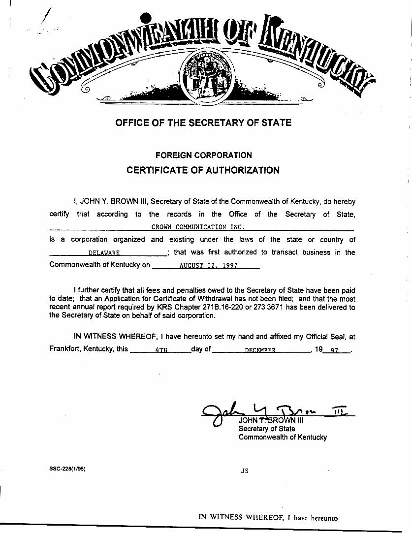
OFFICE OF THE SECRETARY OF STATE
FOREIGN CORPORATION
CERTIFICATE OF AUTHORIZATION
I, JOHN Y. BROWN Ill, Secretary of State of the Commonwealth of Kentucky, do hereby
certify that according to the records in the Office of the Secretary of State,
is a corporation organized and existing under the laws of the state or country of
CROWN COMMUNICATION INC.
D m ; that was first authorized to transact business in the
Commonwealth of Kentucky on AUGUST 12. 1997
I further cehfy that all fees and penalties owed to the Secretary of State have been paid to date; that an Application for Certificate of Withdrawal has not been filed; and that the most recent annual report required by KRS Chapter 2718.16-220 or 273.3671 has been delivered to the Secretary of State on behalf of said corporation.
IN WITNESS WHEREOF, I have hereunto set my hand and affixed my Official Seal, at Frankfort, Kentucky, this 4TH day of 1 1 9 . 9 7 .
" Secretary of State Commonwealth of Kentucky
SSC-228( 1 I961 JS
I
IN WITNESS WHEREOF, I have hereunto
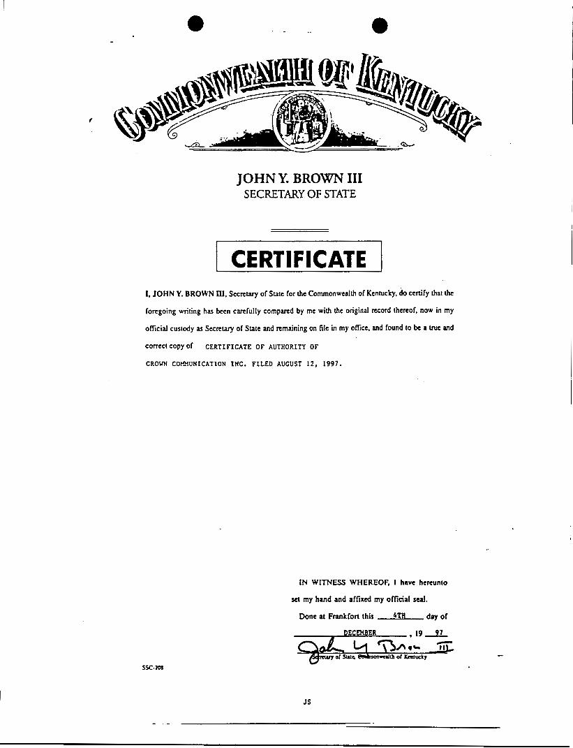
JOHN Y. BROWN 111 SECRETARY OF STATE
I CERTIFICATE I I, JOHN Y. BROWN Ill. Secretivy of State for the Commonwealth of Kentucky. do certify that the
forcgoing writing has bccn carefully compared by me with the original record thereof, now in my
official custody as Secretary of State and remaining on file in my ofice, and found to be a true and
COfRct COPY Of
CROWN C O ~ U N I C A T I O N I N C . FILED AUGUST 12, 1997.
C E R T I F I C A T E O F AUTHORITY OF
IN W I T " WHEREOF, I have hereunto
set my hand and affixed my official real.
Done at Frankfort this bTH day of
D E C M B E R , 1 9 9 1
JS
State of Delaware
Wice of the Secretuy of State
I, EDWARD 5. FREEL, SECRETARY OF STATE OF "€LE STXCR OF
DELAWARE, DO HEREBY CEZITIFY "TRITEL FINANCE, INC." IS DDLY
INCORRORATED UNDER THE LAWS OF llaE STATE OF DELAWAFS AND IS IN
GOOD STANDmG AND HAS A LEGAL CORPORATE EXISTENCE SO FAR AS THE
RECORDS OF TmS OFFICE SHOW, AS OF THE TWENTY-FIRST DAY OF
AUGUST, A.D. 1998.
AND I DO HEREBY FURTHER CERTIFY THAT THE FRANCHISE TAXES
HAVE NOT BEEN ASSESSED TO DATE.
Edward J . Freeel, Secretmy of State
A-CAnOM 2901520 8 3 0 0
981328729
9265495 DATE:
06-21-98
-. I

JacKun MS 392134003 I
- .
EXHIBIT B
SITE DEVELOPMENT PLAN: VICINITY MAP PROPERTY OWNER LISTING 500@ VICINITY MAP LEGAL DESCRIPTIONS FLOOD PLAIN CERTIFICATION SITE PLAN VERTICAL TOWER PROFILE
17

F
cy)
> 6
/ / . . -
r
\
\
,I I / '
/ '
J
II
u/ \
\ \
\
\
\ \
I I
. . . .

T II
P, B s I
8 4' h .
F .%
.

i
z b P
P a 0 \
\ \
/ \, \ \
W
.

I N3MOl A0 do1 P t131N33 VNN31NV a3SOdONd 01 "0-,OSZ I
. 831N33 VNN3lNV 03SOdOHd I
8 t131N33 VNN31NV a3SOdO8d I
k k , d 3 1 N 3 3 VNN31NV Q3SOdOtld
/ 1
EXHIBIT C TOWER AND FOUNDATION DESIGN
18
1
P w e
L W & 3 w o + I T 2 0 -I-
O
o w
u a a
I-d a t n r c
0 L l l -
>v , W
n
I- z > : - 0 0 - \ . Z b _ ] J W - o > - 3 w c + _ ]
/ n r3
w c3 < a
Q
W
Z 0
I- < > w -I W
e W 3 0 I-
U
7 g ? q v R = U
CROWN CASTLE USA, INC.
4w9 MUNFORDV I LLE, KY Wn!! ' I
'APPROVED/ENG. WBR 11/19/1999 )&pim~ O~~~JFJ~ - 1545 Pidco Dr.
21 9-936-4221
I ADDED ANCHOR HEAD SUPPORT DMF 11/19/1999 APPROVED/FOUND. N/A
REV DESCRIPTION OF REVISIONS I N 1 DATE DRAWN BY TRP
A ADDED FOUNDATIONS WBR 11/19/1999 Plymouth, IN 46563-01 28
ENG. FILE NO. A-991 1167A . From: 88784. OFT - 11/16/1999 13: 41 DRAWING NO. 205723-E ~ - 8 8 7 8 4 PAGE 1 0 ~ 1 8
Printed from: 2057231B.DWG - 11/19/1999 09:56 @ 11/23/1999 10:58 ARCHIVE
p$ m
From: 88784 .DFT - 11/16/1999 13: 41 P r i n t e d f rom: [email protected] - 11/16/1999 13: 59 @ 11/23/1999 10: 58
r cu \
I m
lo
\ m
lo m 0
d
-
r(
- m
m w -
a) \ In
- cu \ d
I d - 0 cu -
lo m - 0
m m
I
0 cu m
Plymouth, IN 46563-0128 21 9-936-4221
DRAWN BY TRP
ENG. FILE NO. A-991 1167A DRAWING NO. 205723-E ARCHIVE Q-88784 PAGE 2 OF18
E W
> w 0
cn
H
H
*
m
z J z I o - - z a *
H a o w
0 4 ~ 1 - w o w w H H [ I I H J O l - a z ~ ~ w l - t - z U W O O ~ H U O W
c r o z z a a w I W W W z w a m a 0 1 a 1 - a a w l - x u a a m ~ w
o a a + a L L W Q W ~ I - W H O OIW 1 - ~ n 1 3 a
I- I -z I- a a L Q H > a
w m n z 3 w w 3 Ln I - 0 3 L n Y O
U 3 m W H m x
W I O O J L W Z Jl- J t - ) W O E H
~n > o w I - Z Z I - 0 w [ I W W o H U A I -
1 1 F o ' m I 1 a a w w z l - w o
w l - I - I L n O m I -
0 3 0 1 - - H ~ I - E
Y O H O ~ I - W I
a n ~ ~ l - w w m w
x m a + o ~ - m I- a a
L L o m *
I - - -a H C L m z m O\
. . m a W Z J I - ~ a
CROh& C A S T L E U S A , I N C . M U N F O R D V I L L E . K Y
# 36 X 400' G U Y E D TOWER
1545 Pidco Dr.
I - w
z * O Q * O X m a o ,
MUNFORDVILLE. K Y
1545 Pidco Dr. Plymouth, IN 46563-01 28
2 19-936-422 1

-rl
I u
a w u ~ u a z u z r n c a z w u I - ~ E E L L
OIL LO^
r o w u
w o w m
m W W I H W L 3
W O I
I - I - W I Z I I - 4
m z I -
I -H I -0
I- J O W Z W Q Z J O I U 3 W N I - H O H I - a 0 Oczaaz o o w 3 I K > W O
LL I E w W I - L 3 I O 1 F W I - z w
. . 3 . w I - w m o 3 o w w w z
a WI
+ a a ~ - o 211rna
.A
I a i 1
I h a Y
I- cn W I I- Q: 0 Z
a
0
m r(
I \ + * \
0 * 0 (sr
n
m Y
m U 0 I 0 Z
I- m W 3
I- 3 0 m
a
r
I::
+ . A
I -0 I - C U I OI -LLUCUE
n a Y
m 0 I 0 Z
a
a
a r
I- m W
I- U 0 z
I::
+
.A
I m
TLE USA, I N C . OVILLE, KY
# 36 X 400 ' GUYEO TOWER
APPROVED/ENG. WBR 11/19/1999 p!gix\~ouwu UW&o - - 1545 Pidro Dr
I APPROVED/FOUND.WBR 11/19/1999 - - . . - - - - . .
4 lADDE0 FOUNDATIONS WBR 11/19/1999 Plymouth, IN 46563-0128 i V DESCRIPTION OF REVISIONS
'rom: 88784.DFT - 11/19/1999 08: 53
2 1 9 -936 - 422 1 I N 1 DATE DRAWN BY TRP
205723-E ENG. FILE NO. A-991 1167A DRAWING NO.
PAGE 4 O F 1 8 'rinted from: 2057234A.DWG - 11/19/1999 0 9 : 5 7 @ 11/23/1999 10:58$gARCHIVE Q-88784

W n u H H cn
Y A a cu H v 0 II a I a
11 i
e
0
0
0
-ram: 88784.DFT - 11/16/1999 13: 4 1
J r i n t e d f rom: [email protected] - 11/16/1999 13:59 @ 11/23/1999 10:58
I I 0 I - + J H H W 3 - 3 H
Plymouth, IN 46563-01 28 21 9-936-4221 DRAWN e y TRP
205723-E ENG. FILE NO. A-991 1167A 5 O F 1 8 ARCHIVE Q-88784
W > 000 W H W Z w w H
5 cnI-m a r a Y
H
0 3 0 z z 3 J E cn 0 3 u H O H cnwcn
I-
T I 5 o m 0 b b 0
L L W L L 0
L L H L L l u l l cuzcu cuocu cuucu I I
H W H I-II- \3\
"H W L D W
(u 0 0
0 0 z o z I- u c 03cn 0
o w 0
Lnocn T Z I
0 3 0 I L L 2 0 2 O I - 0 u u
W 2 3 2 a o a cnocn 0 0 0
J
W I W 3 I - 3
H > H
a z a m a m I A I n 3n
H
a w a o a o
a z a
a a
a > a a m a
a w a
+ a +
a ~a
H H
w a w
a a
. c n c n I - I - z z w w E * I wcn
3 W 3 O I 0 w w a H
0 . O m o w w
w at- a H Z
w a a m 3
k o a w z a o w n l o a x a m . a w I z a a . a o
~ O W I - a m w a c n u i a > a H a k a
lo o m z m m k a I - I L D LL m a I I a a a a 5 o w
O I - T I L I- I-cnI-z LL acno a a o 0 O I - o c n w LL I - W N z x I - H
H W H c u 3 II-
z a u
o a c n a z u o r ~ a ~ ~ a a >
O O L L J a a o w
H A W a -1c3a-1 a cnaaa o
cnzo -I
o u z w a m u I - 0
o w c n w
O Z H A H
.. -I a .. H I a cn W H I- Z a H
LL
m
I
I 1 I
I I
i
I I
i
. . . c n c n c n w w w z z z J J A H H H
cn W Z J H
3 m m c n cn w w w - w T I I N T
L L L L L L LL I I l u l l
I - I - I - - I -
a a a I a a a a a a
W W W L n W w w w w w I I I U J I a a a I a I - I - + = I -
U z z z z o o o w o
U c n c n c n z m a a a a a z z i r z z z z a z w w w o w
n m a . o 3 cn w u z
a o > o w a w w Z H .
I- a H I Q
z 0 LL Z 0 0
0 I-
a
a z 0 A W 3
J J
H
a
0 W
LL
u W
cn W cn 1
W I I- O
H
H
a
H
a
n cn Z 0
I- u W Ln
Y
H
a Z
z 0 7 0
W I I-
W
0 LL W
W u -I
Z
W
H
H
a
a
m
a a
H
m
LLU I w a b
a c u
o a a I - ~ H
0 0 0 -
cnI-m I -
z u H O Z
o a a z a a 0 0 o w > I
I - H O 11-a a a ~ ~ + a m
z a a
a > w
I - H ~
w a
H Z
w w L 3 I - 3 3 J A
c n > W
O I - O
I-0 O Z I -
z 3 w W O I I - I - I W
H O Z
cn
a a a
w a ~ I - I - I - L L I - m a a a w a cn cn o o w z z z a z cn I- . z
a m a w OD b b b I b w w w a w m m m ~ m O O O I O w w w - w > > > a > J A A J w w w o w 3 3 3 1 3
. . I - I - I - I - I - cn Z z - . . . . a i 1 1 1 1
wooolno
a I - O L D O b L D zvmmcucu
v
I
I ~
I ~
i I i I i
I
W A Z 3
lo
\ LD
Ln 0 J W 3
Z I
r,
H
3 T cn I- 3 Z 0 z
cn I- J 0
A -I
a
m
a
I - w F I-1
w o a a z ~ a t -
W cncno I -H I - J 3
I LDI-z cuoo I cnI-
w o J A Z A Z O
oacn m w ~
m H acnn
a 3 u . . . m a r \
cn I- W Y u a a m W Z
J
Z 0 cn cn z cn Z
I-
O W
J
3 cn 0 0
H
H
H
a a
H
a a
a a H
Z 0
0 W u -I a a
- w 0 O I - bcn
3 * I I
w - cn 3 - W o m z
J
O I - z L L H O
Y H a cn Z J C n
0 3 I z o c n 3 Z
- 0 0
a
k c H a
H Q H
o c u a a - a a m + a m A W L L Q
w o o
H I - J
. . . 4
MU~ORDVILLE. K Y # 36 400 ' G U Y E O TOWER
- 1545 Pidco Dr. APPROVED/FOUND.N/A

4 ADDED FOUNDATIONS WBR 11/19/1999
E V DESCRIPTION OF REVISIONS
-ram: 88784 .DFT - 11/19/1999 OB: 53 J r i n t e d f rom: 2057236A.OWG - 11/19/1999 0 9 : 5 7 @ 11/23/1999
I N 1 DATE
APPROVED/ENG. WBR 11/19/1999 h&!$mm o [ s i l ~ ~ APPROVEO/FOUND.WBR 11/19/1999 - 1545 Pidco Dr.
Plymouth, IN 46563-01 28 219-936-4221 DRAWN BY TRP
205723-f ENG. FILE NO. A-991 1167A DRAWING NO.
PAGE 6 O F 1 8 10:58$$ARCHIVE Q-88784
Z W J u W
0 J 3 0 I Ln
a
m
J -I
I Ln
cn I- Z H 0 7)
0 J 0 u -I J
a
a
0 0 a a H
I I- H E Z 0 I-
I- -1 3 m Z 0 u Z 0
3
H
a
a
>- * ~a
a
a z m o a w
z 3 0 0
W cno
0
wcn 3 0 0 I-I-
I O w a
a + a a
LLiZ
m a ~a
F H
cn I-
J W
Ln m a H Z Z H
w z
Ln H I
I- I -H 2 3 H 0 0 T W
!-
J O o u u W
a o n o
m
o a
a m v
U J J
H O a . cn
a
a
W z z I u I-
z 3 W Z
H
a
a
1 a w
o a H I- a a o w ~a
cn W I - z I - +
I T
u z a L L - I- H W m O u ! - l - z w w u a a w a m u ~ a
z m m 100 a
a u w aKcrc3
o o o w
W O a L z
O W H O
a o o z L L L L H
m z 0 “J-l L O W J W a a a x
c n m a m a W I I - + a m = P
J m
W z . o z I-0 m H W I - I < H >
u E X o w J J W
II- cn I
L O
LL w U - I
~a
a 1
o a
z a
- v
m M
.A
0 0 0 m
3t:
-3 0 a a -
z a o c n ~ a k
m a w
I - o z . a Z O F W I I - Z I - w
m m
W H W J L n
o o w a w z
z - 0
W H
w w
I W I W I - >
m a a + a a
\ m
m ‘ cu
2 2
o o w w u w w a
a a
z ~ a a w I - a o a a m l a w
z m o u
0 L L J I-a J
H W > a 3 0
U o w >
I-0 L O O H t 3
m z z
z ~ a
0 o r I - w W 3 0 OI -
a c
z a 0 0 I - a ~
LL - x H C E Q J O I
H W u m m ~ a - a - I o m 3 4 LL I F 1
w a o w a Z I -
+ a
> a z o a o ~ u O L L Q
a o a o
z H m ( n H U H
0 3 w * I -u
cnzcnz
zaLL
W O cnw ~a a~ a 3
a a 0
> w I
~ c n a W J O
u 0 cn cn a
W z m
a x a a
0 H >
> u z X H W I - cn 2-1 a a ~m a 3 a 0 0 ‘ cno w z I- J
~a
3cn u a H W L L Q LLa H H
o a
w o Z N Z
0 L L m
~ o a a + cuu e ocn
o w w H ! - U I cn a u a z l z
o n -
u !- a
m
a a a a a
a
>
I-
0
W
W
cn
J
0 cn H
W U O L L a z o ~a a x
o w O I - w w m J [I
J O I
cnwLL O Z I - 0
o a m w
W Q I - ! - m I -
u o W H O m z -
a - ~ a + o m 0 3 0 O J I L L J m O H
LL J W
I - H W a x J W I - ~ a u
(u m
!
m
CROWN C A S T L E U S A , I N C . M U N F O R D V I L L E , K Y
# 36 X 400’ GUYEO TOWER

0
0
a
0
A REV
W L3 Q 0
ADDED FOUNDATIONS WBR 1 1 / 1 9 / 1 9 9 9
DESCRIPTION OF REVISIONS I N 1 DATE
I-
DRAWN BY
z a W Q u A
3
- - _._ - Plymouth, IN 46563-01 28
21 9-936-422 1 TRP
u W H H O
c f a
a w
01
cu
- - - - - - - I I I I I I I I I
I I I I I I L--_I---L I I I I I I I I I + - - I I I I I I I I I
I I I I I I
i----t---r
- - - +
r--i---r
m I
m
2k
a W 3 0 I-
L3 Z H I- u W
W a
. w * w 0
w o w
o a a m LL
~n m a x
w w o - l a a - a W I I - h Z ( 3 z !\Z W L L ~ H u o A
, w w d l ' > LDUIQW
m W L3 Q a Z 0 .
@! >
1 - l J
cnQ w 3 H-0 I - w J . a . I--0 z w N HLI)
0 0 I W
o a
a w
m a a m
H
I
m W c3 Q
Z 0
a
@ . W O w w 00
W d L3 I c n a
m
m I
m I
0 .
Q W > 0 0 w u u a w Lnw > u J Z J O a 0 3 a:
c n . H Z
z a
a + a
w m
H a x men a a
a w w
J 3 J O a w
W I- O Z
H
a . .
I W 0
L3
O W I cn Z
LL
a a
H
H
W I - J c n J c n E W
Q P J W z 3 w - l ~ m z o >
3 0 1 m
CROWN C A S T L E U S A , I N C . M U N F O R D V I L L E . K Y
# 36 X 400 ' G U Y E D TOWER
APPROVEO/FOUNO.WBR 1 1 / 1 9 / 1 9 9 9 1545 Pidco Dr.
I- E : a m - 1 a \ a a - I -
0 O l I - w o w a a - cu w m 0
0 II u H I W
I-
a i m
I' m a
A ADDED FOUNDATIONS WBR 11/19/1999
7EV DESCRIPTION OF REVISIONS I N 1 DATE
From: 88784.DFT - 11/19/1999 O R 5 3
P r i n t e d from: 205723BA.OWG - 11/19/1999 0 9 : 5 7 @ 11/23/1999
-1
F 0 I-
O W
3 0 W
cn W 0 W
a
a H
a
H a m I
a a m a W
m *
CROWN C A S T L E U S A , I N C . M U N F O R D V I L L E . K Y
# 36 X 400' G U Y E D TOWER
APPROVED/ENG. WBR 11/19/1999 - om80 - APPROVEO/FOUND.WBR 11/19/1999 1545 Pidco Or.
Plymouth, IN 46563-01 28 2 1 9 -936 - 422 1
DRAWN BY TRP
ENG. FILE NO. A-991 1167A 205723-1 10:58$QARCHIVE Q-88784 8 O F 1 8
W b * a z v a w e
A m rn :o cn
Z 0
I-
u LL
u W
H
a H
H
I - 3 3 Z w x x
0
I
G o o a a a ~ a a o a a a a a " 0
a \ a I - m I - 0 0
0
I
d a a x m I -
J 0 I ' w II 0 a a
u z m
a
I W rnl- w * * w w *
H A m a a
@: d 0
I
m
T 0
I
I\
I
m x x a a a
a n m a n * a a
w o o
-1-1
I-I- 0 0 FI-
o * w w
a a
aco H d
LL Z
W H
a
3 0 W f a u
a c n w W 0 % w m H e
d n o ID d
II
I- I
a 3 a m x [ ~ a
a m a a a
w o

n m W
m J -I <
n -
v
W
0 -I m
a
- .. 0
ni I
6 ADDED ANCHOR HEAD SUPPORT DMF 11/19/1999 WBR 11/19/1999 A ADDED FOUNDATIONS
REV DESCRIPTION OF REVISIONS I N 1 DATE
From: 88784. DFT - 11/19/1999 08: 53 P r i n t e d f rom: 2057239B.OWG it 11/19/1999 12:01 @ 11/23/1999
I I
APPROVED/ENG. WBR 11/19/1999 )A?.!lpimD - - om@? APPROVED/FOUN~. WBR 11/19/1999 1545 Pidco Dr.
Plymouth, IN 46563-01 28 219-936-4221
DRAWN BY TRP
ENG. FILE NO. A-991 1167A DRAWING NO. 205723- ~ - 8 8 7 8 4 PAGE 9 0 ~ 1 8 io:58$$ARCHIVE
e e w w I - +
I W W 3 0 0
m z z
J a . I
3 l - - 0 r m J z < o w z W -J I I - w a e 3 O I I - w I m w o m 3 e
a m - J
m m w
z n z o a o w e m n
L L ~ oeocu oe\ W I - z o o - z z I A < < \ lY + - w e Z W I W w w o 3 o e z o a < +
I -v ioe
J W U O L L L L 0 0 0 - N l- w w e I Z Z w \ - - > + J J
A
3 I - w o m
a
< a m I - e 1 o e u L L W -
3 w 9 0 1
I- w w c 3 0 > <I - - a +
w a W U - I w z w m u e
I- + m o i t oa i t - Z
(D I
T 2 ?
n , i-aJ e - 0
vi n
5 >
o J -1
03- LL
o e 0 LL
> J(D W I - w < a I < - a X o w e w a m
oj
a < C n J Z w - 0 ELL-
i u i
6 -
e z w r a o w o n m o m
’:1 I
L
I / CROWN C-ASTLE USA, INC.
MUNFORDV I LLE, K Y # 36 X 400’ GUY ANCHORS

0
0
v
vi a E
W v, O n I
E O W I - z
E z o 0 0
I - 2 - 0
nI-
I - v i
.-(
nI- a o
m Z A -0, v z m r
E
I w w w o ~ a a
w
a
-I (3 Z
I- o W E
0 I- Z n
n
0 - L W (nu E a a n
W E A
5 N
0
c\i
I : * I
O
d I
m
I
b
II I I- (3 Z W -I
0 0 E
0
(r, N m
c
W
&
e
t a nor' a > n o
a +
Z W
0
W o w a w r n E
0 > z J O -10
3 - a 0 --I
r E Q v ,
W E m w E - 3
-10 J W < E
W W v,
z 0
I- a J -I a I - m v , I
n
2s cd
W d E O
n u W Z I - v , l - - v , z - - x L W
W -I m a i-
W W cn v, W N
v,
W E
3 n E
n
a
a I r j > w 3c3
E o z L O
c3a a
ui n
5 >
o-I -I
03- . L L
m a 3 v, L"E W 0 Z LL Y > o J r o - w I l - w I- 6 0
I - x w O W
s a w - a
E d E W o w av , Z I - a 0 1 - a . o - , v i
2 C n J Z -1E w - 0 a w E L - z a - I- o 3 n a
n a - nv, r a o a - u z w
m o m
-I- O W 0 I -0 W I - - - Z E O L L
w o a U CROWN CASTLE USA, INC.
MUNFORDV I LLE, K Y # 36 X 400' GUY ANCHORS
APPROVED/ENG. WBR 11/19/1999 ~ ~ p i m l m l - omml - 6 ADDED ANCHOR HEAD SUPPORT DMF 11/19/1999 APPROVED/FOUND. WBR 11/19/1999 1545 Pidco Dr. A ADDED FOUNDATIONS WBR 11/19/1999 Plymouth, IN 46563-01 28
21 9-936-4221 I I N 1 I DATE DRAWN BY ITRPI REV DESCRIPTION OF REVISIONS
From: 88784. DFT - 11/19/1999 08: 53 ENG. FILE NO. A-991 1167A DRAWING NO. 205723 P r i n t e d f r o m : 205723AB.DWG * 11/19/1999 11.51 @ 11/23/1999 l o : 5 8 $ i A R C H I V E ~ - 8 8 7 8 4 PAGE 10 O F 1 8
I

e a
0 J O 0 H O l a
[I
w a
a
+ - - I
o u e H
>. I-
CROWN C A S T L E U S A , I N C . M U N F O R D V I L L E . K Y
# 36 X 400 ' GUY ANCHORS i
a a x
@ a k
A ADDED FOUNDATIONS WBR
REV DESCRIPTION OF REVISIONS I N 1
L o a w
11/19/1999
DATE
0 u J -I H H a a I- t-
z w W L o o 0
- w W L o w W
tn tn
I
DRAWN BY
m
TRP
cu
Ln 0 Z W
I L
e o
~m +I-: a o a m k a -J
I- \o Y b +
0 0 w o I w K I b O H m 3 O I - o m - [I-- I
w m m
J H
I- a w 0 I
I c z u w II a w m
a a z I - m 2 s wa a x x v + a a w z a a
~ n n a a
000
0 W I: 0 a LL
Y 0 0 I
m m
--I
u
>. I-
0
e
a
a H
cn Z 0
t-
0
LL
u W
Ln 4t 0 0 - a m
W II 0
I - a I C Y c3 H m w - 3 l o [I:
w t n
w o + I -
E X H a x o OLL
H
a H
H
n
a
a a x m I - a a
a
a z n o n u a
a o a t - m
0 A I -
t - a
L3 Z
u 0 LL z W
H
H
Plymouth, IN 46563-0128 I I I
_ _ _ _ ~ ~ ARCHIVE Q-88784 I PAGE 1 1 OF18

0
0
lo
n z z z w w 3 o u -1 1 * I
a a m n J o w 2 W J I F W Z
m m a 1 o x ! - w I m w u m 3 a z o z a
a m 0 L O oaocu W I - z o o
a + w * a I - m o a Z W I W w w u 3 o a z o
a o w
o a \
~ a a \ H Z Z I
o a k J W a o k k 0 0 0 H&I !- w w a I z z W \ ” ~
> + J J
d .. 0
cu \
J J a
a
Y
W
0 J cn
J a 3 I - w o m a a .
m I - a 1 o a a L L W H
3 w v o x
I-
w w a o > a!--n n ! -
w a
m a a W O J w z w
!- * m n X H Z x n a
/
m 0 > 1 U J
J O D H
‘ L L
0
m m a
LL > J u 3 W I - w a m z a HQ.
a m
X o w a w
5 . .
I + ! - x o a
a o k a H
r a o a x w w o n m o m
o w o W ! - H
Ill CROWN CASTLE USA, I N C .
MUNFORDVILLE, KY # 36 X 400 ’ GUY ANCHORS
APPROVED/ENG. WBR 11/19/1999 jlkpmrn - omli - APPROVEO/FOUNO.WBR 11/19/1999 1545 Pidco Dr.
WBR 11/19/1999 Plymouth, IN 46563-01 2 8
I 219-936-4221
ENG. FILE NO. A-991 1167A DRAWING NO.
A ADDED FOUNDATIONS TRP REV DESCRIPTION OF REVISIONS I N 1 DATE DRAWN BY
From: 88784.DFT - 11/19/1999 08:53 205723 PAGE 12 O F 1 8 P r i n t e d f rom: 205723CA.DWG - 11/19/1999 09:58 @ 11/23/1999 lO:58$$ARCHIVE Q-88784

OD OD m m
H
W cn W 0 - -I I . L3 I - c n Z
a a o w l- I - 2 u
U W 2 0 U o u H 0 I - I I- H O z ol- n ol- a 0 0
CDODmCU ; Jt:
* m
l- Lo
I
0 /
T = lD
. I
/ " '
- v
w w 0 0
a L 3
a a a u
L W
cn 0 t
3 U J
J r n ~ -
W ' L n u 1 c n m z w m cn m u a > w a W 0 o w I- Z L n u cn Y > W u w
m u u > z -10 -10
3 5
o m W
cnz I
U a m w u
3 J o J W
a + a w
a
H H
m w U H
a a
z 0 H t-
J J a . c n l z v H m
OD w v
P * t c 3 3 2 a H E
o n L O
a
l - m
a 0 H M
u a
W W cn cn W N
cn W U a P 0 U 4 .
t W 3 L 3
H
r m
a a n
a 0 2 L O
- u 1 i o
I
io I
OD
In
I
1
TLE USA, I N C . D V I L L E , KY
# 36 X 400' GUY ANCHORS
APPROVED/ENG. WER 11/19/1999 ,
APPROVEO/FOUNO.WER 11/19/1999 A/pimm om&
1545 Pidco Dr. -
4 AODED FOUNDATIONS WER 11/19/1999 Plymouth, IN 46563-01 28 i V DESCRIPTION OF REVISIONS 219-936-4221 I N 1 DATE DRAWN B Y TRP
ENG. FILE NO. A-991 1167A 'rom: 88784 .DFT - 11/19/1999 08: 53 DRAWING NO.
' r i n t e d f r o m : 205723DA.DWG - 11/19/1999 09:58 @ 11/23/1999 10:58$\ARCHIVE Q-88784 PAGE 13 O F 1 8 205723-E
APPROVED/ENG. WBR 1 1 / 1 9 / 1 9 9 9 &?imm om[xo APPROVEO/FOUNO.WBR 1 1 / 1 9 / 1 9 9 9 - 1545 Pidco Dr.
21 9-936-4221 A ADDED FOUNDATIONS WBR 1 1 / 1 9 / 1 9 9 9 Plymouth, IN 46563-01 28
I N 1 DATE DRAWN BY TRP ?EV DESCRIPTION OF REVISIONS
205723-E From: 8 8 7 8 4 . D F T - 1 1 / 1 9 / 1 9 9 9 08:53 ENG. FILE NO. A-991 1167A DRAWING NO.
Q-88784 PAGE 14 O F 1 8 P r i n t e d from: 205723EA.DWG - 1 1 / 1 9 / 1 9 9 9 0 9 : 5 8 @ 1 1 / 2 3 / 1 9 9 9 10:58$QARCHIVE
A / 0
a
Y 0 0 r 0 m m
J
u a > I-
d
a H
O
0 -1 H
I- W 0
a
a u J H
I- W 0
d a
0 0 0 m a
a 2 0 a d H
> In I-
Ln Z 0
I-
u LL
0 W
Ln ?t 0 0 v u ) In
W II 0
I L 3 L3 HIn w e 3u)
H
a H
H
n
a ~ - a
a a a r m t - w m a a w o I -+ a
Ln 0
W
0 u -I -I z a a H H
0 -1 a
I- I- . w W u ) o 0
- w w a w w
Ln Ln
I
I c -0
- lm a 1 I -+ : a oa001- I- \o
Y h I - 0 0 w o I ?t a r k 0
c
0, I-0 o m w " a Y T
0 cu
a
H Ln 3 0 I - o m -
r r ~a
a z n o n o
x o ob- a +
a w m a E z I - m 3 5
I I - z u w II a
a + a o a ~ - m
0 A I -
L3 Z
u 0 LL z W
H
a
H
a
cu w a a x x v + a a
w a n
0 0 0
a z a a a a
0 W I 0 LL
a
I I
ASTLE USA, I N C . ORDVILLE, K Y
# 36 X 4 0 0 ' GUY ANCHORS

0
- m W 0
m J 1
H
a Y
W
0 1 m
a
.74 . . 0
cu
I I
w w I-!-
T W W 3 0 0
a n
m z z
a a m - 1 I I - W Z
m m
~ m z a a 0 w
a m o
3 w z JJ -I
1 3 > T I - w 1 cnw z o z a
L O 3 c r o c u
o n \ J J I z u o + z z I r + Z W I W L l w u 3
J W Q O L L L L J 0 0. I c u
~ a ” a \ LI . a - m o a
azo sat-
- w w 1 I 2 2
J
3 I - w u m
a
a a . m I -
a 1 ocra
3 w V O I
I-
L L W H
w w c 3 0 > a t - u & I -
w u - l w z w
I-
w a
m a n * m o * H Z x o a
= i c o I
m i I
y
\
/
‘ L L a3 Inn 0 LL
Ace W
O W a w Q U I a
H I -
o w u 2 0 4
W I - H E O L L
n r w a u
r a u w o n m u m
T 1
STLE USA, I N C . RDVILLE. KY
# 36 X 400 ’ GUY ANCHORS
4 ADDED FOUNDATIONS WBR 11/19/1999 IV DESCRIPTION OF REVISIONS IN1 DATE DRAWN BY TRP
Plymouth, IN 46563-0128 219-936-4221
ENG. FILE NO. A-991 1167A ’rom: 88784.0FT - 11/19/1999 08: 53 DRAWING NO. 205723-E ’ r i n t e d f rom: 205723FA.DWG - 11/19/1999 09:58 @ 11/23/1999 10:5B$ Q-88784 PAGE 15 O F 1 8
W m 0 -
I - c n a: o w I-z z o o u I - z H O OI- O I -
r -
a
H
a 0
9 ADDED FOUNDATIONS WBR 11/19/1999
EV DESCRIPTION OF REVISIONS
-ram: 88784.DFT - 11/19/1999 00: 53
' r i n t e d from: 205723GA.DWG - 11/19/1999 09:58 @ 11/23/1999
I N 1 DATE
W -1 m z I- u W [I
0 I- z H
0
a
APPROVED/ENG. WBR 11/19/1999 IAPi rnB om@, - - 1545 Pidco Dr.
Plymouth, IN 46563-0128 2 1 9 -936 - 422 1
APPROVED/FOUND.WBR 11/19/1999
DRAWN BY TRP
205723-E ENG. FILE NO. A-991 1 167A 1 0 : 5 8 $ ~ A R C H I V E Q-88784 16 0 ~ 1 8
o a a > z w
0 o u W u w
m a u > z -10 -10
13. o m W
cnz I
a + a w
a
H H
a a m m w w a a H
a a
3 -10 -1w
w W cn z 0 H I-
-1 A
c n l z v H m
OD w v
3 *
t m 3 2 U H 3
L O
a
a . ~ - m
a 0 H H
a a o a
W J m a I-
W W cn cn W N
cn W a 3 0
H
a
a a . ~m
m a t W 3 m
Q a o z L O
' L L c n a m m a W 0 z LL
CROWN EASTLE USA, I N C . MUNFORDVILLE. K Y
# 36 X 400 ' GUY ANCHORS
4
DRAWN B Y
Y 0 0 I
Ln m
-1
u
0
r(
a
n H
>- I-
TRP REV DESCRIPTION OF REVISIONS I N 1 DATE
0
a u a
n
a
n
-J
I- W
H
0 0 0 m 4
[I -1
0
>-
a
n e H
-I H
d a
n I- W
e I-
Ln z 0
I- 4 0
LL
u W
Ln * 0 0 vu) LD
W II 0
4
I C 3 C3 H m w - 3u)
4
4 z W L n
w o I-I- a
H
H
H
a
+ a
a m I - a <
0 u cn 0 z W
-1 1
4 4 I- I-
. w W l D 0 0 - w W L o w W
Ln Ln
H H
I
O # I-0 o m w m a T
0 cu
k
H
c n I II t WI- a
a w z m
aI-
a w m a a z t - m 3 3 w a a x x v + a a a z n n ~ n n
a a n
a
U H I W w 3 I - H a #
- I w c u C 3 - 1 c u - z - u w II
I I -2
0 0 0
W I 0
4 0
A I - 4
0 4
C3 Z u 0 LL Z W
+ a + m
!-I
a
H
a
cu
CROWN C U S T L E U S A , I N C . M U N F O R D V I L L E . K Y
# 36 X 400 ' GUY ANCHORS
1545 Pidco Dr. A I ADDED FOUNDATIONS I WBR I l l /19/1999 I I I Plymouth, IN 46563-0128
ARCHIVE Q-88784 I PAGE 17 0 ~ 1 8

\
n L
Z W
Z 3
m
W Y V
X O n V J J a m a W I -
Y E O 0 mc3wI- o w z a J -0 n a c - - l n w
I- a o - 3 w a 3 0
0 m-- (r,
W E w E: E -
E W l U W 0 E W E Z rr 0 *em,
W
-I
4 I- W
( D o W
N W cn
Y
I
LL
-I Y
a I- W 0
W W cn
Y 0 O n J-l
o I - W W I -
I m a a E o
n c 3 n z n w
a: =IU m a o w
O W E -lE-
E - 3
w W E E I E
(D b. N O *N -u
3 W
>
0 I-
Y
a
0
I- C-
m
N
cn w
cn Z W
I
n
t- . o ~m a I-+ -I < z a I-
' Y o n o I- w o : E X O * - b 3 0 I C ) ULn. w m - r r e - *
- I w U - I +
(3,z aI-
I I -z o w 11
r r w m ar rz I - m 3 3 w a rr x x
0 0 0 m I - r r r r * z a a
- a n 6 <
n W 2 LT 0 LL
n Y 0
a > - : I - L n
0 0 d (3, <
I LT J
0
>
a
a e Y
I-
O '
0
Q E O c3 a- a mcn
o w z x a ~ w o w I- 01: x J CDW m e
0 I-I cno a z o a
0 W a I/,
" Z
0 LT 0 LL Z Y
W LT
I I
I I r
CROWNU CASTLE USA, I NC. MUNFORDV I LLE, K Y
# 36 X 400' I GUY ANCHORS
APPROVED/ENG. WBR 1 1 / 1 9 / 1 9 9 9 jhpimrn - - ommi APPROVED/FOUND. 1545 Pidco Dr. WBR 1 1 / 1 9 / 1 9 9 9
Plymouth, IN 46563-01 28 B ADDED ANCHOR HEAD SUPPORT DMF 1 1 / 1 9 / 1 9 9 9 219-936-4221
DESCRIPTION OF REVISIONS I N 1 DATE DRAWN BY TRP REV
From: 88784 . DFT - 11/19/1999 08: 53 ENG. FILE NO. A-991 1167A DRAWING NO. 205723 P r i n t e d f rom: 205723IB.DWG * 1 1 / 1 9 / 1 9 9 9 12: 03 @ 1 1 / 2 3 / 1 9 9 9 10: 58$QARCHIVE ~ - 8 8 7 8 4 PAGE 18 0~18
EXHIBIT D COMPETING UTILITIES, CORPORATIONS, OR PERSONS LIST
19

Collocation Statement 263-1 10-OOA - Munfordville
TriTel Communications Inc. has stated their need to install antenna’s at 400’ above ground level in the vicinity of 1-65 and Rowletts-Caves Spring Road. The proposed site will improve the digital/portable usage in that area.
There are no current towers within a 2 mile radius of the TriTel search area, according to the data available through the PSC and through our own observation.

EXHIBIT E COLLOCATION REPORT
20
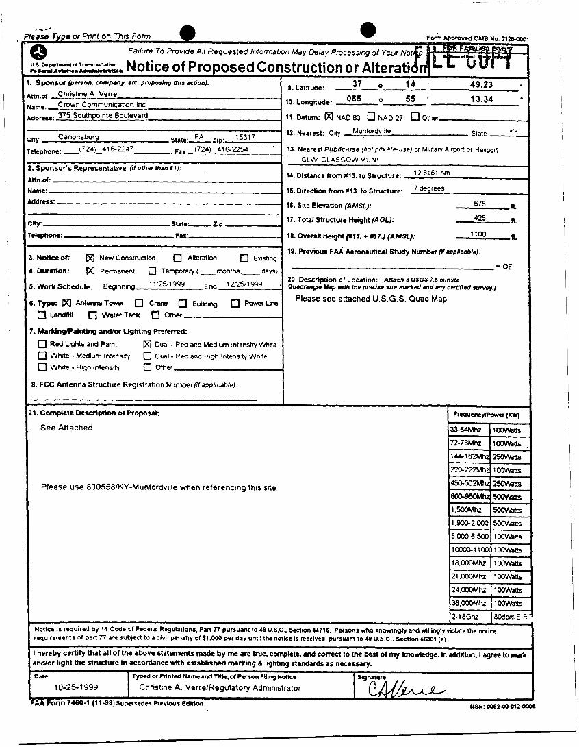
..\.-' ,as8 Type or Pnnt on Thrs Form
Date
10-25.1999
LS bpumurn d 7 rnmponrbn l...,..,A...(fi...-,,,-t.. Notice of Proposed Cor
Typed or Printed Nune and TI&. d P a w n Filing Nakt
Christine A VerrelRegulatory Administrator
Sponsor (petson. company. .IC. pruposlng mts action):
tn,ol: Chnstine A Vene Crown Communicahan Inc- rme. ___ _ _ -375 Southpointe Boulevard
ty: Canonsburg State.- PA Zip 15317 rltphont: -(!..?!&?s F~~ 1724) 4162254
, Sponsor's Representative fif Other u m t V Rn d:
a m .
¶dress:
. N d k e o t New Construdm 0 Afteratm 0 Eashng
. Dumbon: Permanent 0 Temporary ( -mnths-mci
. Work Schedule Beginnng 999 End 999
.Type: AntennaTowr 0 Crane 0 BwWtng 0 Powerbe 0 Landfill 0 WaterTank 0 otkr . MarklnglPalnting andlor Lighting Preferred:
0 Red Ltghts and Pamt 0 White - M e d i m Inters*{ 0 Whne - Hgh Intensdy
Dual - Red ard Medium ntensw W - d e
0 Oval - Red and High htensty Whne 0 m e r
3 . FCC Antenna Structure Registrabon Nwnbei applicable)
1, Complete Desrxiption ot Proposal:
See Attached
WBNo 27-
;truction or AltetatiJn! L. 8 . Latnuee: 37 0 14 ' 49.23
085 0 5s ' 13.34 0. Longitude:
1.Datum: W N A D 8 3 QrYAD27 nother
12. Nearest: Cty Munfordvll'e State -- - 13. Neared Publk-use (nor p r r a - w s e ) or Mllnary A.por? or qeiiwrt
14. Dlstancc from $13.10 Structure: l 2 nrn
IS. bredion from bl3. to Structure:
d e
GLW SL4SrJOW MUNl
degrees
16. Site Ekvation (AMSL): 675 a 17. Total Stmcturc Hught (AGL): 42s R
18. ovmg Height lpru. + H74 (n4J.X): 1100 h 19. Previous FAA Aeronautical Study Nwnber (Rwficable) .
__
20. Descrtption of Location: i n r a C k d USGS 7.5 minute Ou.dnn#e Uop Wmr me preute ~e M e d und m y cemffed wrvey.)
Please see attached U.S.G S. Quad Map
Please use 800558/KY-Munfordville m e n referencing this sne.

EXHIBIT G APPLICATION TO KENTUCKY AIRPORT ZONING COMMISSION
22

1. NATURE( I A TYPE i B I
i (YEAREST SECOSD, Munfordville ' j ( I ) DIST.4SCE TO 4B
, 3 7 O 11' 49.23' I
I (2) DIRECTIOS TO 4B I
I 8 5 O 55' 13.34" I
U m D E
I
L O X W D E i
I i See attached.
I GLU': G l a s g o ~ Jlunicipai j (1) DIST.LWE TO R 1 3 X A Y B. HEIGHT OF S I R U C l l R E . ISCLl.DISG 4256 4
.4PPlRTES.LYCES .OD LIGHTS (ABOVE !
12.8161 SM CROLTD LEVEL) i
7 degrees !
(2) DlRECTlOS TO AIRPORT C. O\TRILL HEIGHT (AMSL) (.\+B)
3
! I i n I \LTEMTIO\ TE\IPOR+RI' j E \ D I ? 2 5 99
[ 3.4. APPLICANT - NAME, ADDRESS & TELEPHONE I Please use 800558'KY-Munfordville when
j .A. N U K E D FOR THE PROTECTION OF AIR NAVIGATION (FLAGS. SPHERES. ETC.)
B OBSTRUCnOh',MARUD IN ACCORDAVCE WITH 601,KAR 50100 (FA4 AC 70nJ60-11)
1 referencing this proposed site.
I !
I Christine A. \ ' m e . Regulatop Administrator C ro un C o m m u n i c ;1 t i on s 375 Southpoints Blvd. Canonsburg. PA 153 17 724-4 16-2247t2258
I
B. REPRESE.\TATI\+ OF APPLICAW - SAhIE. ADDRESS & TELEPHOSE
1
1. LOCATION OF STRUCTURE 5. HEIGHT & ELEVATION
1 j APPROVED
j DlS.4PPRO\ZD - - I I D.%TE
~D I B (E
I I I
I I I I I 1 6
m
a
CmTE A S S O C I A T E S I N C .
GEO TECHNICAL ENGINEERING STUDY CROWN COMMUNICA TIONS
PROPOSED TOWER KY 263- 7 70-OOA RO WLETTS-CA VE SPRINGS ROAD
MUNFORDVILLE, KENTUCKY A TC PROJECT NO. 73000.9 7 74
Prepared For:
Crown Cornrnunica tions. 1 IO0 1 Bluegrass Parkway, Suite 330
Louisville, Kentucky 40299
A tten tion: Mr. George Zaharis

A S S O C I A T E S I N C . 1 1 I I 1 1 I I I I ~1
I 1 I I 11 11
October 29, 1999
Crown Communications 11001 Bluegrass Parkway, Suite 330 Louisville, Kentucky 40299
Attention: Mr. George Zaharis
Re: Geotechnical Engineering Study Proposed Munfordville Communications Tower Rowletts-Cave Springs Road Munfordville, Kentucky ATC Project No. 13800.91 13
Gentlemen:
Transmitted herewith is our geotechnical engineering report for the referenced project as authorized in accordance with our January 15, 1998 proposal for environmental and geotechnical support services. This report contains our findings, an engineering interpretation of these findings with respect to the available project characteristics, and recommendations to aid design and construction of the tower foundations. We appreciate the opportunity to be of service to you on this project. If you have any questions regarding this report, please contact our office.
Cordially,
ATC Associates Inc.
Michael A. Highkhew, EIT Staff Engineer
2815 Watterson Trail Louisville, Kentucky 40299
502.267.8355 Fax 502.267.8528
David L. Warder, PE Regional Geotechnical Engineer
Copies submitted: (4) Mr. George Zaharis; Crown Communications
LETTER OF TRANSMITTAL
TABLE OF CONTENTS
1. PURPOSE AND SCOPE ........................................................................................................... 4
2. PROJECT CHARACTERISTICS ........................................................................................... 4
3. SUBSURFACE CONDITIONS ................................................................................................ 5
4. FOUNDATION DESIGN RECOMMENDATIONS .............................................................. 6
4.1. TOWER FOUNDATION ............................................................................................................. 7
4.2. GUY ANCHORS ....................................................................................................................... 8
4.3. EQUIPMENT BUILDING ........................................................................................................... 8
5. GENERAL CONSTRUCTION PROCEDURES AND RECOMMENDATIONS ............ 10
5.1. TOWER FOUNDATION EXCAVATION ..................................................................................... 10
5.2. FILL COMPACTION ............................................................................................................... 11
5.3. CONSTRUCTION DEWATERING ............................................................................................. 12
6. FIELD INVESTIGATION ...................................................................................................... 12
7. LABORATORY INVESTIGATION ..................................................................................... 13
8. WARRANTY AND LIMITATIONS OF STUDY ................................................................ 13
APPENDIX
SITE VICINITY MAP GEOTECHNICAL BORING LOG SOIL SAMPLE CLASSIFICATION
I I u I 1 I I I I

Geotechnical Engineering Investigation Proposed Communications Transmission Tower
KY 263-1 10-OOA Munfordville, Kentucky Project No. 13000.9114
GEOTECHNICAL ENGINEERING INVESTIGATION
Proposed Communications Transmission Tower
Rowletts-Cave Springs Road Munfordville, Kentucky
ATC Project No. 13000.91 14
KY 263- 1 1 0-OOA
1. PURPOSE AND SCOPE
The purpose of this study was to determine the general subsurface conditions at the location of
the proposed tower by drilling four test borings and to evaluate this data with respect to
foundation concept and design for the proposed tower and guy anchors. Also included is an
evaluation of the site with respect to potential construction problems and recommendations
dealing with quality control during construction.
2. PROJECT CHARACTERISTICS
Crown Communications is planning to construct a guyed communications tower within the Stinson
property on Rowletts-Cave Springs Road in Munfordville, Hart County, Kentucky. The proposed
tower location is shown on the Boring Location Plan in the Appendix. At the time of our field
exploration, the site was partially wooded.
The tower will reportedly be about 400 feet in height and will be supported on a concrete
foundation with guy anchors radiating from the tower 120 degrees apart. The guy cables will be
secured by concrete dead-weight anchors located approximately 250 feet from the tower center.
No foundation design loads have been provided. We assume that the maximum downward load
on the tower will not exceed about 200 kips and that the maximum uplift and lateral forces in the

I I I I I I I I I 1 U I I 0 1 i I I
Geotechnical Engineering Investigation Proposed Communications Transmission Tower
Munforhtille, Kentucky Project No. 13000.9114
KY 263-110-OOA
guy anchors will be in the range of 75 to 100 kips/anchor. The development will also include a
small equipment building near the base of the tower.
3. SUBSURFACE CONDITIONS
The subsurface conditions were explored by drilling test borings at the proposed tower location and
three proposed anchor locations, which were staked in the field by the project surveyor. The
Geotechnical Soil Test Boring Logs, which are included in the Appendix, describe the materials
and conditions encountered. A sheet defining the terms and symbols used on the boring logs and
explaining the Standard Penetration Test (SPT) procedure can also be found in the Appendix. The
general subsurface conditions disclosed by the test borings are discussed in the following
paragraphs.
According to the United States Geological Survey, Horse Cave, Kentucky geologic quadrangle
map, the site is underlain by the St. Genevieve Mississippian age limestone bedrock formations.
The soilhedrock interface associated with these formations tends to be highly irregular and the
depth to rock can vary abruptly over short horizontal distances. This formation is prone to
dissolution and the subsequent development of karst features such as sinkholes, widened vertical
joints and horizontal bedding planes.
About 4 inches of topsoil were encountered at the ground surface at each boring location. The
borings then encountered apparently natural clay (CH) of relatively high plasticity to the depths of
3.0 to 4.0 feet. The SPT N-values in the clayey soils ranged from 16 to 47 blows per foot,
indicating a very stiff to hard consistency. Pocket penetrometer values used to estimate the
unconfined compressive strength of cohesive soil ranged from 3.5 to 6.0 tons per square foot. The
anchor borings were terminated at the auger refusal depth of 4.0 feet below ground surface. The
tower boring encountered auger refusal at 3 feet below the existing ground surface. A ten foot core

Geotechnical Engineering Investigation Proposed Communications Transmission Tower
Munfordville, Kentucky Project No. 13000.91 I4
KY 263-11 0-OOA
run was made in boring B-1 from 3 to 13 feet below the ground surface and revealed gray
weathered limestone that contained clay seams. The recovery ratio on the core run was 45 percent
and RQD value was 15 percent.
Groundwater observations made at completion of the soil drilling operations indicated the borings
to be dry. It must be noted, however, that short term water readings in clayey soils are not
necessarily a reliable indication of the actual groundwater level. Furthermore, it must be
emphasized that the groundwater level is generally not stationary, but will fluctuate seasonally.
According to the Seismic Zone Map of the United States, Munfordville, Kentucky is within Zone
1. In this system, Zone 3 is the most seismically active while Zone 0 has the lowest earthquake
potential. Considering the subsurface conditions encountered at the site as they relate to Table
16-J in the 1997 Uniform Building Code, the soil-profile type is S,.
4. FOUNDATION DESIGN RECOMMENDATIONS
The following design recommendations have been developed on the basis of the previously
described project characteristics (Section 2.0) and subsurface conditions (Section 3.0). Particular
care should be taken during construction to identify any conditions that vary from those described
in Section 3.0. This office should be notified if variable conditions are noted, the project
description included herein is incorrect, or if the proposed structure location is changed to establish
whether revisions to the following recommendations are necessary.

'. Geotechnical Engineering Investigation
Proposed Communications Transmission Tower
Munfordville, Kentucky Project No. 13000.91 I4
KY 263-1 IO-OOA
4.1. Tower Foundation
Our findings indicate that the proposed tower can be supported on a spread footing bearing in the
hard clay or underlying limestone at or below a depth of 2.5 feet below the existing ground
surface. The footing can be designed for a net allowable soil pressure of 5,000 lbs/sq.ft. It is
important that the foundation excavation be carefully inspected as described in Section 5.1 to
insure that the foundation will bear on suitable material. While foundations bearing on limestone
are often designed for a much higher allowable pressure, it would be necessary to remove the
portion of the rock that contains clay seams in order to use the higher pressure.
The site is underlain by limestone bedrock that is susceptible to dissolution and the subsequent
development of karst features such as voids and sinkholes in the natural soil overburden.
Construction in a sinkhole prone area is accompanied by some risk of internal soil erosion and
ground subsidence. While it is not possible to investigate or design to completely eliminate the
possibility of future sinkhole related problems, compliance with the recommendations set forth in
this report can help to reduce this risk. In any event, it is important that the owner understand and
accept this risk.
In using net pressures, the weight of the foundation and backfill over the foundation need not be
considered; hence, only loads applied at or above the existing ground surface elevation need to
be used for dimensioning the foundation. The bottom of the tower foundation should bear at a
depth of at least 2.5 feet below the final exterior grade for frost protection.
It is estimated that resulting foundation settlement should not exceed about 0.75 inches. Careful
field control will contribute substantially to minimizing the settlements.
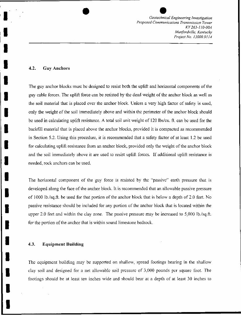
Geotechnical Engineering Investigation Proposed Communications Transtnission Tower
Munfordville, Kentucky Project No. 13000.9114
KY 263-1 IO-OOA
I 4.2. Guy Anchors
The guy anchor blocks must be designed to resist both the uplift and horizontal components of the
guy cable forces. The uplift force can be resisted by the dead weight of the anchor block as well as
the soil material that is placed over the anchor block. Unless a very high factor of safety is used,
only the weight of the soil immediately above and within the perimeter of the anchor block should
be used in calculating uplift resistance. A total soil unit weight of 120 lbs/cu. ft. can be used for the
backfill material that is placed above the anchor blocks, provided it is compacted as recommended
in Section 5.2. Using this procedure, it is recommended that a safety factor of at least 1.2 be used
for calculating uplift resistance from an anchor block, provided only the weight of the anchor block
and the soil immediately above it are used to resist uplift forces. If additional uplift resistance is
needed, rock anchors can be used.
The horizontal component of the guy force is resisted by the “passive” earth pressure that is
developed along the face of the anchor block. It is recommended that an allowable passive pressure
of 1000 lb./sq.ft. be used for that portion of the anchor block that is below a depth of 2.0 feet. No
passive resistance should be included for any portion of the anchor block that is located within the
upper 2.0 feet and within the clay zone. The passive pressure may be increased to 5,000 lb./sq.ft.
for the portion of the anchor that is within sound limestone bedrock.
4.3. Equipment Building
The equipment building may be supported on shallow, spread footings bearing in the shallow
clay soil and designed for a net allowable soil pressure of 3,000 pounds per square foot. The
footings should be at least ten inches wide and should bear at a depth of at least 30 inches to
Geotechnical Engineering tnvestigation Proposed Communications Transmission Tower
Munfordville, Kentucky Project No. 13000.91 14
KY 263-1 IO-OOA
minimize the effects of frost action. Any topsoil, frozen or excessively soft material must be
removed beneath footings.
The floor slab for the new equipment building may be subgrade supported on a properly prepared
subgrade. The slab should be designed and adequately reinforced to resist the loads proposed.
The exposed subgrade should be carefully inspected by probing and testing as needed. Any
organic material (topsoil) still in place, frozen or excessively soft soil and other undesirable
materials should be removed.
Once the subgrade has been properly prepared and evaluated, fill may be placed to attain desired
final grades. Any non-organic, naturally occurring, non-expansive soils can be used for structural
fill, including those encountered on this site, pending evaluation by the geotechnical engineer.
All engineered fill should be compacted to a dry density of at least 100 percent of the standard
Proctor maximum dry density (ASTM D698). The compaction should be accomplished by
placing the fill in about eight inch loose lifts and mechanically compacting each lift to at least the
specified density. Field tests should be performed on each lift as necessary to insure that
adequate compaction is being achieved.
1 8 1 8 E 1
Surface run-off water should be drained away from the foundation excavations and not allowed
to pond. It is recommended that all foundation concrete be placed the same day the excavation is
made.
I ' . -
I I I 1 I 1 1
i
Geotechnical Engineering tnvestigation Proposed Communications Transmission Tower
Munfordville, Kentucky Project No. 13000.91 I4
KY 263-1 IO-00A
5. GENERAL CONSTRUCTION PROCEDURES AND RECOMMENDATIONS
It is possible that variations in subsurface conditions will be encountered during construction. It
is recommended that the geotechnical engineer or a representative be retained to perform
continuous inspection and review during construction of the soils-related phases of the work.
This will permit correlation between the test boring data and the actual soil conditions
encountered during construction.
5.1. Tower Foundation Excavation
The tower foundation excavation should be inspected by the geotechnical engineer or a qualified
soils technician to insure that all undesirable material is removed and that the foundation will
bear on satisfactory material as decried in Section 4.1. At the time of such inspection, it will be
necessary to make hand auger borings or use a hand penetration device in the base of the
foundation excavation to insure that the soils below the base are satisfactory for foundation
support. The necessary depth of penetration will be established during inspection.
If undercutting is required in order to remove unsuitable materials at the tower foundation
location, the foundation bearing elevation may be re-established by backfilling after all
undesirable materials have been removed or the foundation can be placed at the lower depth. The
undercut excavation beneath the foundation should extend to suitable bearing soils and the
dimensions of the excavation base should be determined by imaginary planes extending outward
and down on a 2 (vertical) to 1 (horizontal) slope from the base perimeter of the foundation. The
entire excavation should than be refilled with a well-compacted granular fill as described in
Section 5.2 or lean concrete may be used. Special care should be exercised to remove any

1 I 1 1
‘I 1 t 8
Geotechnical Engineering Investigation Proposed Communications Transmission Tower
Munfordville, Kentucky Project No. 13000.91 14
KY 263-1 IO-OOA
sloughed, loose or soft materials near the base of the excavation slopes with benches as
necessary, to insure that no pockets of loose or soft materials will be left in place along the
excavation slopes below the foundation bearing level.
Soils exposed in the base of the foundation excavation should be protected against any
detrimental changes in conditions such as from disturbance, rain and freezing. Surface run-off
water should be drained away from the excavation and not allowed to pond. If possible, all
concrete should be placed that same day the excavation is made. If this is not practical, the
excavation should be adequately protect.
5.2. Fill Compaction
All engineered fil l placed adjacent to and above the tower foundation and guy anchor blocks
should be compacted to a dry density of at least 95 percent of the standard Proctor maximum dry
density (ASTM D-698). This minimum compaction requirement should be increased to 100
percent for any fill placed below the tower foundation bearing elevation. Any fill placed beneath
the tower foundation should be limited to well-graded sand and gravel or crushed stone. The
compaction should be accomplished by placing the fill in about 8 inch (or less) loose lifts and
mechanically compacting each lift to at least the specified minimum dry density. Field density
tests should be performed on each lift as necessary to insure that adequate moisture conditioning
and compaction is being achieved.
Compaction by flooding is not considered acceptable. This method will generally not achieve the
desired compaction and the large quantities of water will tend to soften the foundation soils.
I 1

Geotechnical Engineering fnvestigation Proposed Communications Transmission Tower
Munfordville, Kentucky Project No. 13000.91 1.1
KY 263-110-OOA
5.3. Construction Dewatering
No serious dewatering problems are anticipated. At the time of our investigation, the ground
water level appeared to be below the anticipated excavation depths. However, depending upon
seasonal conditions, some minor seepage into excavations may be experienced. It is anticipated
that any such seepage can be handled by conventional dewatering methods such as pumping
from sumps.
6. FIELD INVESTIGATION
One boring was drilled at the proposed tower center and one was drilled at each of the three anchor
locations, all of which were established in the field by the project surveyor. Split-spoon samples
were obtained by the Standard Penetration Test (SPT) procedure (ASTM D1586) in the overburden
portion of the test borings. The borings were terminated at auger refusal depths 3.0 to 4.0 feet. The
bedrock was cored between depths of 3 and 13 feet in Boring B- 1. Representative portions of the
soil samples were sealed in glass jars and returned to our laboratory.
The boring logs are included in the Appendix along with a sheet defining the terms and symbols
used on the logs and an explanation of the Standard Penetration Test (SPT) procedure. The logs
present visual descriptions of the soil strata encountered, Unified System soil classifications,
groundwater observations, sampling information, laboratory test results, and other pertinent field
data and observations.
Geotechnical Engineering Investigation Proposed Communications Transmission Tower
Miinfordville, Kentucky Project No. 13000.9114
KY 263-1 IO-00A
7. LABORATORY INVESTIGATION
The split-spoon samples were inspected and visually classified by a geotechnical engineer in
general accordance with the Unified Soil Classification System and the field boring log was edited
as necessary. To aid in classifying the soil samples and to check the general soil characteristics,
pocket penetrometer tests were performed on selected samples. The results of these tests are
included on the boring logs.
8. WARRANTY AND LIMITATIONS OF STUDY
Our professional services have been performed, our findings obtained, and our recommendations
prepared in accordance with generally accepted geotechnical engineering principles and practices.
This warranty is in lieu of all other warranties, either express or implied. ATC Associates Inc. is
not responsible for the independent conclusions, opinions or recommendations made by others
based on the field exploration and laboratory test data presented in this report.
A geotechnical study is inherently limited since the engineering recommendations are developed
from information obtained from a test boring that only depicts subsurface conditions at the specific
location, time and depth shown on the log. Soil conditions at other locations may differ from those
encountered in the test boring, and the passage of time may cause the soil conditions to change
from those described in this report.
The nature and extent of variation and change in the subsurface conditions at the site may not
become evident until the course of construction. Construction monitoring by the geotechnical
engineer or a representative is therefore considered necessary to verify the subsurface conditions
and to check that the soils connected construction phases are properly completed. If significant
variations or changes are in evidence, it may then be necessary to reevaluate the recommendations
1
Geotechnical Engineering Investigation Proposed Communications Transmission Tower
Munfordville, Kentucky Project No. 13000.9l14
KY 263- I IO-OOA
of this report.. Furthermore, if the project characteristics are altered significantly from those
discussed in this report, if the project information contained in this report is incorrect, or if
additional information becomes available, a review must be made by this office to determine if any
modification in the recommendations will be required.

APPENDIX
BORING LOCATION PLAN
GEOTECHNICAL BORING LOG
SOIL SAMPLE CLASSIFICATION
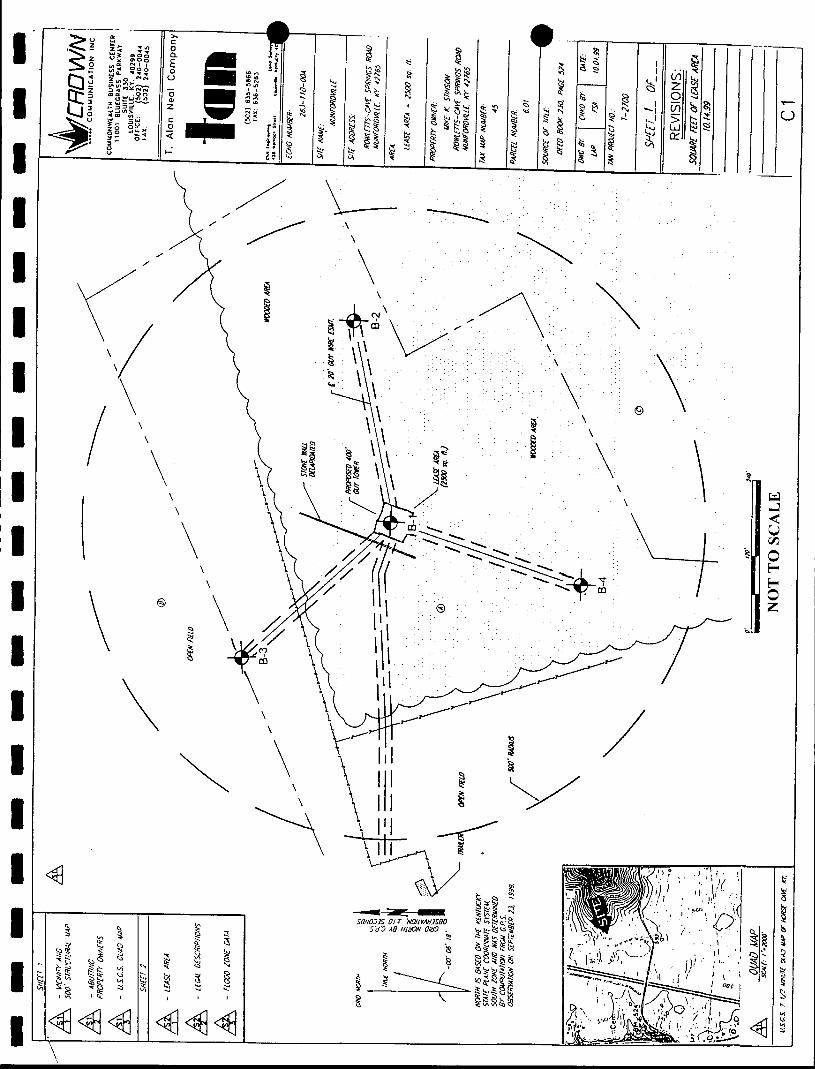
/
\
\ \
\
8
\ \ \
\ '\

’ m T C Associates Inc. 28 15 Watterson Trail Louisville, KY 40299 0
GEOTECHNICAL BORING LOG
CLIENT: Crown Communications BORING NUMBER: B-1 PROJECT: Proposed Tower KY 263-1 10-00A PROJECT NUMBER: 13000.91 14
LOCATION: Rowletts-Cave Springs Road, Munfordville, Kentucky PROJECT MANAGER: Mike Hightchew
-
ELE‘
-
Surface Elevation: Date Started: 10/28/99
Date Completed: 10/28/99
MATERIAL
DESCRIPTION
W C H ) - red, hard, rock fragments
Limestone - gray, hard, moderately weathered with clay seams
- - - - - - - - - - - Limestone - gray, hard, slightly
weathered with clay seams
TERMINATED
Hammer Weight: 140 Ibs. Hammer Drop: 30 in. Drill Foreman: Jim Wharton
Hole Dia.: 6.5 in. Boring Method: HSA
Supervisor: Beth Stuber
LAYER
DEPTH
& TYPE -
0.4
3.c
8.0
13.0
2
BLOW - 12-1 7-:
5016
SAMPLE DATA -
I-YF - SP’
S P
RC
PP,ts
4.5
5.5
NOTES
Approximately 4 inches of topsoil
Auger Refusal at 3 feet below ground surface
Rock cored from 3 to I3 feet
RQD= 15%
3orehole was dry prior to leginning coring operations
Page 1 of I

. .
PP,tsf
I 1
I I
W T C Associates Inc. 28 15 Watterson Trail
GEOTECHNICAL BORING LOG
Louisville, KY 40299
CLIENT: Crown Communications BORING NUMBER: B-2 PROJECT: Proposed Tower KY 263-1 10-00A PROJECT NUMBER: 13000.91 14
LOCATION: Rowletts-Cave Springs Road, Munfordville, Kentucky PROJECT MANAGER: Mike Hightchew
Surface Elevation: Date Started: 10/28/99
Date Completed: 10/28/99
Hammer Weight: 140 Ibs. Hole Dia.: 6.5 in. Hammer Drop: 30 in. Boring Method: HSA Drill Foreman: Jim Wharton Supervisor: Beth Stuber
ELEV MATERIAL
DESCRIPTION
1 =CHI - red, very stiff
AUGER REFUSAL
LAYER
DEPTH
& TYPE
T W I SAMPLE DATA
BLOW!
12-13-1
50/3
50/3
- TYI -
SP
SP
SP'
3.5
6.0
_--
NOTES
Approximately 4 inches of topsoil
Borehole was dry at the completion of boring activities
Page I of I

e 1.. * a T C Associates Inc.
ELEV
1 I I I I i I I 1 I I I I I I I I I
MATERIAL
DESCRIPTION
%y (CH) - red, very stiff, with chert SOll
fragments
-
28 15 Watterson Trail GEOTECHNICAL
BORING LOG Louisville, KY 40299
CLIENT: Crown Communications BORING NUMBER: B-3 PROJECT: Proposed Tower KY 263-1 10-00A PROJECT NUMBER: 13000.9 1 14
LOCATION: Rowletts-Cave Springs Road, Munfordville, Kentucky PROJECT MANAGER: Mike Hightchew
Surface Elevation: Date Started: 10128199
Date Completed: 10/28/99
AUGER REFUSAL
Hammer Weight: 140 Ibs. Hole Dia.: 6.5 in. Boring Method: HSA Hammer Drop: 30 in.
Drill Foreman: Jim Wharton Supervisor: Beth Stuber
LAYER
DEPTH
& TYPE -
0.4
4.0
BLOW:
9-1 1- I (
5016
SAMPLE DATA
PP,tsf
6.0
6.0
NOTES
Approximately 4 inches of topsoil
Borehole was dry at the completion of boring activities
Page I of I
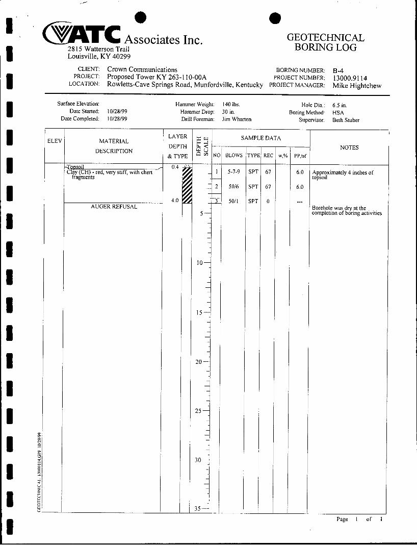
I I I 1 I I 1 I I I I I I 1 B I
ELEV
m T C Associates Inc.
- PP,tsf
28 15 Watterson Trail GEOTECHNICAL
BORING LOG Louisville, KY 40299
CLIENT: Crown Communications BORING NUMBER: B-4 PROJECT: Proposed Tower KY 263- 1 1 0-OOA PROJECT NUMBER: 13000.91 14
LOCATION: Rowletts-Cave Springs Road, Munfordville, Kentucky PROJECT MANAGER: Mike Hightchew
Surface Elevation: Date Started: 10128199
Date Completed: 10128199
Hole Dia.: 6.5 in, Hammer Weight: 140 Ibs. Hammer Drop: 30 in. Boring Method: HSA Drill Foreman: Jim Wharton Supervisor: Beth Stuber
MATERIAL
DESCRIPTION
a C S ] - red, very stiff, with chert II
fragments
AUGER REFUSAL
LAYER
DEPTH
& TYPE BLOW:
5-7-9
5016
5011
SAMPLE DATA
6.0
6.0
--_
NOTES
Approximately 4 inches of topsoil
Borehole was dry at the completion of boring activities
Page 1 of 1

i* ,I I I I
I
I
I I I I I I J I I I 1 1
SOIL SAMPLE CLASSIFICATION
GRANULAR S O L S (Silt, Sand, Gravel and Combinations)
Densitv Very Loose - 5 blows/ft. or less
Medun Dense - 11 to 30 blowdft. Dense - 3 1 to 50 blows/ft. Very Dense - 51 blows/ft. or more
Loose - 6 to 10 blowS/ft.
Relative Proportions Percent Trace 1 - 10 Little 11 -20 Some 21 -35 And 36 - 50
Particle Size Identification Boulders Cobbles Gravel - Coarse - 1 to 3 inch
- % to 1 inch - % to % inch
- 0.42 to 2.00 mm
- 8 inch diameter or more - 3 to 8 inch diameter
Medium Fine
- Medium Sand - Coarse - 2.00 mm to % inch
- Fine - Silt
- 0.073 to 0.42 IIUTI - 0.002 to 0.074 ~IUII Clay - less than 0.002 mm
COHESIVE SOILS (Clay, Silt and Combinations)
Consistencv Plasticiw Very Soli - 3 blows/ft. or less Degree of Plasticity Plasticity Index Soli - 4 to 5 biowdft. None to Slight 0 - 4
Slight 5 - 7
High to Very High
Medium St t f f Stiff - 1 1 to 15 blowslft. Very S t B - 16 to 30 blo\vS/ft.
- 6 to 10 blows/ft. Medium 8 - 22
over 22 Hard - 3 1 blows/ft. or more
Classfication on logs are made by visual inspection of samples unless otherwise undicated.
Standard Penetration Test - Driving a 2.0'' O.D., 1-3/8" I.D. split-spoon sampler a &stance of 12 inches into undisturbed soil with a 140 pound hammer free falling ;1 distance of 30 inches. The sample is initially dnven 6 inches to penetrate into unlstubed soil. then the test is performed. The number of hammer blows for seating the spoon and malung the test are recorded for each 6 inches of penetration on the boring log (Example: 6-84). The standard penetration test N-value can be obtained by adding the last two figures (Le. 8+9=17 blows/ft.). (ASTM D-1586)
Strata Changes - In the column "Material Description" on the boring log, the horizontal lines represent strata changes. A solid line ( - ) represents an actually observed change. a dashed line (- - - -) represents an estimated change.
Ground Water observations were made st the times indicated. Porosity of soil s t ra ta weather conditions. site topography. etc. may cause changes in the water levels indicated on the logs.
m T C

1 ' . I I I I I I 1 I I I I 'I I I I I I I
ROCK CORE CLASSIFICATION
CONTINUITY
Description Incompetent Competent Fairly Continuous Continuous
HARDNESS
Descriution VeIy Soft soft
Moderately Hard
Hard
Very Hard
WEATHERING
Description Completely
Hi g 11 1:
Modera tei!.
SI ightly
Fresh
BEDDING
Description Parting Band Thin Bed blediuni Bed Tliicli Bed MassI\ e
ROCK OUALITY (ROD)
Core Recoveni. Yo Description ROD. % 0 - 40 Very Poor 0 - 25
25 - 50 -10 - 70 Poor 70 - YO Fair 50- 75 90 - 100 Good 75 - 90
Excellent 90 - 100
Definition Can be broken with fingers Can be scratched with fingernail Only edges can be broken with fingers Can be easily scratched with krufe Cannot be scratched with fingernail Difficult to scratch with knde Hard hammer blow to break specimen Cannot be scratched with knife Several hard hammer blows to break specimen
Definition Rock decomposed to soil Rock fabric &L structiire completely destroyed Most minerals are dcconiposed Texture indistinct but fabric preserved Strength grciitly reduced Discoloration througbout and weaker minerals decoriiposed Texture presen.ed but strength less than fresh rock Discoloration around open fractures Strength presen,ed No sign of decomposition or discoloration
Thickness. inclics less than 0.3
0 . 3 - 2 . 5 2 . 5 - 0 0 6.0 - I l . ( I
12.0 - 36.0 grcater than 36
m T C

EXHIBIT I DIRECTIONS TO WCF SITE
24

Direction: 1-65 South. Get off of Exit 65 (Munfordville Exit). Make a left onto HWY 31 W South. Follow 31 W South for 4.2 miles. You’ll see a red sign that’s says “Mamouth Onyx Cave”. Take a right at that sign. That Nil1 be Hwy 335. Go .02 mile on Hwy. 335 and make a right onto Rowletts-Cave Springs Road. Follow qowletts-Cave Springs Road (winding road and stay on blacktop) for 2 miles. At the 2 mile point make a right nto small gravel road. Follow gravel road to the end. The site is up on Summer Seat Knob on the east side ol :he trailer home.
Prepared by: George Zaharis - (502) 494-6543
Pursuant to Company instructions Rev. 3 10120l97 Candidate Location Map

ECHO # 263-1 IO-OOA - Munfordville
LEASE AGISEEPIENT
THIS LEASE AGREEMENT ("Lease") is made this day of
, 1999, by and behveen Mike K. Stinson, Owner, having a mailing address of P.O.
Box 2043, Cave City, KY 42127 (heieinafte? "Lessor") and CROWN COP~IUNICATION
INC., a Delaware corporation, doing :business in Kentucky as CROWN COPJBIUNICATIONS,
* . e s I . '
B z ? .* l
1 - 2 o b
with an oflice address of 375 Southpointe Boulevard, Canonsburg, Pennsylvania, 153 17
(hereinafter "Lessee"). -- -
WITNESSETH
WHEREAS, Lessor is the owner of certain real property located at Rowletts Cave Springs
Road, in Hart County, Kentucky, which Lessor acquired by Deed dated 11/14/96, of record in
Deed Book Volume 230, Page 524, in the Office of the Clerk of Hart County, Kentucky
(I'Propertv'l), which real property is 'more particularly described on Exhibit "A" attached hereto;
and Lessor and Lessee desire to enter into this Lease of a portion thereof.
The terms, covenants &d conditions of this Lease are as follows:
1.
. : 7 .-'
"
L.'
.. I .
t,:.:
. ') I. .
Description of Leased%-opertv. Lessor does hereby lease to Lessee a portion of
the Property described as a 50' X 50' parcel of land [and 10' around all guy anchors] together
with a non-exclusive right for ingress and egress seven days per week, twenty-four (24) hours per
day, on foot or motor vehicle, including trucks, along a thirty (30) feet wide right-of-way extending
from the nearest public right-of-way, together with the right to install, replace and maintain utility
wires, poles, cables, conduits and pipes, all of which are generally described in Exhibit "B" which
is attached hereto and incorporated herein ("Leased Premises"). The Leased Premises also

includes: (a) Lessee's right to install, maintain and replace the towers guy wires; and, (b) aerial
rights over Lessor's property extended from the guy anchor points to the guy attachment points on
the tower. Lessor hereby grants to Lessee the right to survey the Leased Premises and said survey
may then be initialed by the parties to indicate acceptance thereof, which acceptance shall not be
unreasonably withheld, and said survey shall then be attached hereto and incorporated herein as a
new Exhibit "B", replacing the original Exhibit "By' and shall control in the event of discrepancies
between it and the original Exhibit "B". In the event any public utility is unable or unwilling to use
the described right-of-way, Lessor hereby agrees to grant an additional right-of-way either to the
Lessee or directly to the public utility at no cost and in a location acceptable to Lessee,
-- --
2. Lease Term. This Lease shall be for an initial term of twenty-five (25) years
beginning on the date of commencement of construction. This Lease shall automatically be
extended for three (3) subsequent twenty-five (25) year terms ("Renewal Terms") unless Lessee
terminates it pursuant to the terms set forth herein. The Initial Term and any Renewal Terms shall
be collectively referred to as the "Lease Term".
7 Due Dilipence Period. Lessee shall pay to Lessor 3 .
pon the complete execution of this Lease. Lessee shall have twelve (1 2) months from
the date of complete execution of this Lease within which to analyze the suitability of the Leased
Premises for its intended use (the "Due Diligence Period"). Lessee and its agents, engineers,
surveyors and other representatives shall have the right to enter upon the Property to inspect,
examine, conduct soil borings, drainage testing, material sampling, and other geological or
engineering tests or studies of the Property, to apply for and obtain all licenses and permits
required for Lessee's use of the Leased Premises from all applicable governmental or regulatory . I
--

entities, and otherwise to do those things on or off the Property that, in the sole opinion of
Lessee, are necessary to determine the physical condition of the Property, the environmental
history of the Property, Lessor’s title to the Property and the feasibility or suitability of the
Property for Lessee’s use of the property as defined within this Lease, all at Lessee’s expense.
Lessee shall not be liable to Lessor or any third party on account of any pre-existing
defect or condition on or with respect to the Property, whether or not such defect or condition is
disclosed by Lessee’s inspection.
If, upon the expirat& of the Due Diligence Period, Lessee has not obtained all the - certificates, permits, licenses and other approvals deemed necessary by Lessee within Lessee’s
sole discretion, including the successful conclusion of all appeals or the termination of any
I appeal periods (the “Approvals”), to utilize the Leased Premises for Lessee’s intended use,
Lessee may extend the Due Diligence Period for another Twelve (12) month period upon writ.3n
notice to Lessor. In consideration of the extension of the Due Diligence Period, Lessee shall pay
to Lessor an extension fee in the amount of
If, in the sole and absolute opinion of Lessee, the Leased Premises are not suitable f .
for Lessee‘s intended use, or Lessee determines that the operation of a communications facility
on or within the Leased Premises would not be in Lessee’s best interest, Lessee shall have the
right at any time prior to the expiration of the Due Diligence Period, or any extension thereof, to
terminate this Lease by sending written notice of termination to Lessor. Notwithstanding other
provisions in this Lease, this Lease shall automatically terminate upon the expiration of the Due
Diligence Period, or any extension thereof, if Lessee has not i) commenced the construction of
the proposed wireless communications facility, ii) given Lessor notice of extension of the Due

..
Diligence Period, or iii) given Lessor written notice of commencement of the Lease term
without commencement of construction.
4. - Rent. Lessee shall pay to Lessor, the total sum of
per year to be paid in equal installments of
:+- , per month as rent for the Leased Premises (“Base Rent”). Payment shall begin upon the
date of commencement of construction by Lessee of Lessee’s communications facility on the
.L &.
Leased Premises (“Rent Commencement Date”). Such payment shall be made in advance,
without demand therefor, within-fifteen (15) days of the Rent Commencement Date m d by the
tenth of each month thereafter. In the event the Rent Commencement Date starts or this Lease ends - -
on any day other than the first day of the month then the rent will be prorated for the partial months.
After the fifth full year from the date of this Lease the Base Rent shall be increased.by fifteen
percent (15%) over the Base Rent that was in efTect during the previous five (5) year period. For
every five (5) year period thereafter, the Base Rent shall be increased by fifteen percent (1 5%) over
the previous five (5) year period.
5. Lessee’s Right to Terminate. Lessee shall have the unilateral right to terminate
this Lease at any time by providing Lessor six (6) months prior written notice. Said termination
shall be effective immediately upon the expiration of said six (6) month period.
6 . Effect of Termination bv Lessee. Upon termination of this Lease by Lessee, this
Lease shall become null and void and all of the parties shall have no fiu-ther obligations except that
any monies owed up to date of termination shall be paid within thirty (30) days of the termination
date.
7. Surrender of Propertv. Upon expiration or termination of this Lease, Lessee
shall, within sixty (60) days, remove its building(s), tower, and all above ground fixtures and
restore the Leased Premises to its original condition, reasonable wear and tear excepted.
8. Use of Propertv and Maintenance. The Leased Premises and all easements,
rights and privileges herein granted shall be used only for the purpose of constructing, maintaining
and operating a wireless communications tower and all facilities and uses incidental thereto. It is
understood and agreed that Lessee intends to sublease the Leased Premises or license the use of its
wireless communications tower and facilities to any number of other parties engaged in the conduct
or provision of wireless communications services. Lessee shall place a security fence consisting of
chain link or comparable construction around the perimeter of the Leased Premises (excluding the
- -
right-of-way easement, although Lessee shall have the right to place a gate across the easement in
order to restrict vehicular access to the Lease Premises). All improvements shall be undertaken at
the Lessee's sole expense or the expense of its customers, clients or agents. Lessee will maintain
the Leased Premises in a reasonable and safe condition. Lessor will take no action that would
adversely affect the status of the Leased Premises with respect to the proposed use by Lessee.
9. Removal of Obstructions. Lessee has the right to remove obstructions, including
but not limited to vegetation, which may encroach upon, interfere with or present a hazard to
Lessee's use of the Leased Premises. Lessee shall be responsible for disposing of any materials
related to the removal of obstructions.
10. Hazardous Substances and Materials. Lessee shall not (either with or without
negligence) cause or permit the use, storage, generation, escape, disposal or release of any
Hazardous Substances in any manner not sanctioned by law. In all events, Lessee shall indemnify
and hold Lessor harmless from any and all claims, damages, fines, judgments, penalties, costs,
liabilities or losses (including, without limitation, any and all sums paid for settlement of claims,
attorneys', consultants' and experts' fees) from the presence or release of any Hazardous
Substances on the Leased Premises if caused by Lessee or persons acting under Lessee. Lessee
shall execute such affidavits, representations and the like from time to time as Lessor may
reasonably request concerning Lessee's best knowledge and belief as to the presence of Hazardous
Substances on the Leased Premises.
Lessor shall not (either with or without negligence) cause or permit the use, storage,
generation, escape, disposal or release of any Hazardous Substances or Hazardous Wastes in any
manner not sanctioned by law. In all events, Lessor shall indemnify and hold Lessee harmless from T -
any and all claims, damages, fines, judgments, penalties, costs, liabilities or losses (including,
without limitation, any and all sums paid for settlement of claims, attorneys', consultants' and
experts' fees) from the presence or release of any Hazardous Substances or Hazardous Wastes on
the Property unless caused by Lessee or persons acting under Lessee. Lessor shall execute such
affidavits, representations and the like from time to time as Lessee may reasonably request
concerning Lessor's best knowledge and belief as to the presence of Hazardous Substances or
Hazardous Wastes on the Property.
For purposes of this Lease, the term "Hazardous Substances'' shall be as defined in the
Comprehensive Environmental Response, Compensation and Liability Act, 42 U.S.C. Section
960 1, et seq. and any regulations promulgated pursuant thereto, and as used to define "Hazardous
Wastes'' in the Resource Conservation and Recovery Act, 42 U.S.C. Section 6901, et seq., and any
regulations promulgated thereto.
11. Insurance. At all times during the Lease Term, Lessee, at its sole expense, shall

obtain and keep in force insurance which may be required by any federal, state or local statute or
ordinance of any governmental body having jurisdiction in connection with the operation of
Lessee's business upon the Leased Premises.
I
12. Waiver of Subrogation. The parties hereby waive any and all rights of action for
negligence against the other which may hereafter arise on account of damage to the Leased
Premises resulting from any fire or other casualty of the kind covered by property insurance
policies with extended coverage regardless of whether or not, or in what amount, such insurance is
now or hereafter carried by the parties, or either of them, but only to the extent that policies
providing such insurance permit without prejudice thereto waiver of subrogation or release of
others.
-
13. Eminent Domain. If the whole or any part of the Leased Premises is taken by
eminent domain or any similar legal power or by purchase in lieu of such taking or condemnation,
and as a result thereof the use and enjoyment of the Leased Premises by Lessee is substantially
impaired, Lessee will have the option to: (a) declare this Lease null and void and there shall
thereafter be no hrther liability or obligation by either of the parties hereunder; or (b) remain in
possession of that portion of the Leased Premises not taken, in which event there shall be an
equitable adjustment in rent on account of the portion of the Leased Premises so taken. With either
option, Lessee hereby reserves the ability to contest the taking andor directly proceed to obtain an
award, or a portion of the award, allocated to Lessee's interest in the Leased Premises.
14. Sale of Prouertv. If, at any time during the Lease Term, Lessor decides to sell all
or part of the Property, of which the Leased Premises is a part, to a purchaser other than Lessee,
such sale shall be under and subject to this Lease and Lessee's rights hereunder and any sale by
Lessor of the portion of the Leased Premises underlying the right-of-way herein granted shall be
under and subject to the right of Lessee in and to said right-of-way.
15. Recording. Lessor acknowledges that Lessee intends to record a Memorandum of
this Lease with the appropriate recording officer and that Lessor shall execute same promptly upon
Lessee's request.
16. Indemnification and Hold Harmless. Each party shall indemnify and hold the
other harmless against any claim of liability or loss from personal injury or property damage arising
from the use and occupancy of the Leased Premises (or the parcel of which the Leased Premises is
a part) by the party, its servants er agents, excepting, however, such claims or damages as may be
due to or caused by the acts of the other party, or its servants or agents.
17. Lessor's Covenant of Title. Lessor covenants that Lessor is seized of good and
sufficient title and interest to the Property and has full authority to enter into and execute this Lease.
Lessor fiirther covenants that: (a) there are no aspects of title that might interfere with or be adverse
to Lessee's interests in and intended use of the Leased Premises; and (b) title shall be such that
Lessee will have the ability to obtain title insurance at regular rates.
Interference with Lessee's Business. Without the prior written consent of Lessee,
Lessor covenants to restrict, on the parcel of which the Leased Premises is now a part, the
18.
construction, installation or operation of any wireless communications facilities which emit radio
frequencies.
19. Lessor's Estoppel. Upon Lessee's request in writing, Lessor shall promptly
execute, acknowledge and deliver to Lessee an estoppel certificate certifying that (a) this Lease has
not been modified or, if modified, stating the nature of such modification and certifying that this
Lease, as so modified, is in full force and effect, (b) stating the date to which the Base Rent and
other charges are paid in advance, if at all, and (c) acknowledge that there are not, to Lessor's
knowledge, any uncured defaults on the part of either party hereunder, for the benefit of any
creditors of Lessee.
20. Ouiet Eniovment. Lessor covenants that Lessee, on paying the Base Rent and
performing covenants, shall peaceably and quietly have, hold and enjoy the Leased Premises.
21. Mortgwes. At Lessor's option, this Lease shall be subordinate to any mortgage by
Lessor which may now or hereafter affect all of the Property including the Leased Premises,
provided that any such mortgage shall recognize the validity of this Lease in the event of
foreclosure of Lessor's interest and also recognize Lessee's right to remain in possession and have
access to the Leased Premises. IR-the event that the Leased Premises is encumbered by a mortgage,
Lessor shall obtain and furnish to Lessee a nondisturbance agreement for each such mortgage in
recordable form. Lessee shall execute whatever instruments may reasonably be required to
evidence this subordination clause.
22. Default. In the event there is a default by Lessee with respect to any of the
provisions of this Lease or its obligations under it, including the payment of the Base Rent, Lessor
shall give Lessee written notice of such default. After receipt of such written notice, Lessee shall
have fifteen (15) days in which to cure any monetary default and thirty (30) days in which to cure
any non-monetary default, provided Lessee shall have such extended period as may be required
beyond the thirty (30) days if the nature of the cure is such that it reasonably requires more than
thirty (30) days to cure and Lessee commences the cure within the thirty (30) day period and
thereafter continuously and diligently pursues the cure to completion. Lessor may not maintain any
action or effect any remedies for default against Lessee unless and until Lessee has failed to cure
the same within the time periods provided in this paragraph.
23. Entire Aareement. It is agreed and understood that this Lease contains all of the
agreements, promises and understandings between Lessor and Lessee and that no verbal or oral

agreements, promises or understandings shall be binding upon either Lessor or Lessee in any
dispute, controversy or proceeding at law and any addition, variation or modification to this Lease
shall be void and ineffective unless made in writing and signed by the parties hereto.
24. Construction of Document. Lessor and Lessee acknowledge that this document
shall not be construed in favor of or against the drafter and that this document shall not be
construed as an offer until such time as it is executed by one of the parties and then tendered to the
other party.
25. Applicable Law. This Lease and the performance thereof shall be governed,
interpreted, construed and regulated by the laws of the Commonwealth of Kentucky. -
26. Notices. All notices hereunder shall be in writing and shall be given by (a)
established express delivery service which maintains delivery records, (b) hand delivery, or (c)
certified or registered mail, postage prepaid, return receipt requested. Notices may also be given
by facsimile transmission, provided that the notice is concurrently given by one of the above
methods. Notices are effective upon receipt, or upon attempted delivery if delivery is refiised or
if delivery is impossible because of failure to provide reasonable means for accomplishing
delivery. The notices shall be sent to the parties at the following addresses:
Mike K. Stinson P.O. Box 2043 Cave City, KY 42127
Crown Communication Inc. 375 Southpointe Blvd. Canonsburg, PA 153 17 - Attn: Legal Department Fax: (724) 4 16 - 2200
With a copy to: Crown Communication Inc. 11001 Bluegrass Parkway, Suite 330 Louisville, KY 40299 - Attn: Property Management
27. Assignment and Sublease. Lessee has the right, within its sole discretion, to assign and
sublease this Lease and any assignment or sublease of said Lease shall be binding upon the
successors, assigns, heirs and legal representatives of the respective parties hereto. Assignment of
this Lease shall be effective 'upon Lessee sending written notice to Lessor at Lessor's mailing
address stated above and shall relieve Lessee from any further liability or obligation accruing
hereunder.
Additionally, Lessee may, upon notice to Lessor, mortgage or grant a security
interest in this Lease and Lessee's equipment, and may assign this Lease and such equipment to any
such mortgagees or holders of security interests including their successors or assigns (hereinafter
collectively referred to as "MortPagees"). In such event, Lessor shall execute such consent to
leasehold financing as may reasonably be required by Mortgagees. Lessor agrees to notify Lessee
and Lessee's Mortgagees simultaneously of any default by Lessee and to give Mortgagees the same
right to cure any default as Lessee except that the cure period for any Mortgagee shall not be less
than ten (10) days after receipt of the default notice.
Partial Invaliditv. If any provision of this Lease is found to be void or invalid,
then such invalidity shall not affect the remaining provisions of this Lease, which shall continue in
full force and effect.
28.
29. Successors and Assigns. Except as otherwise provided herein, this Lease shall
extend to and bind the heirs, personal representatives, successors and assigns of the parties hereto.
30. Taxes. Any taxes, including, but not limited to, real estate and personal property
tzxes, assessed on the Leased Premises shall be paid by the Lessor, provided that Lessee shall pay
any taxes levied on Lessee's personal property located or installed on the Leased Premises and
hrther provided that Lessee shall pay that portion of any real property taxes directly attributable to
the improvements constructed by Lessee. Lessee reserves the right to challenge any such

assessment at Lessee’s expense and Lessor agrees to cooperate with Lessee in connection with any
such challenge.
31.
Leased Premises. Prior to offering the Leased Premises for sale to a third party, Lessor shall give
to Lessee the ROFO by written notice to purchase said Leased Premises. Lessee shall have thirty
(30) business days upon receipt of Lessor’s notice to accept or waive the ROFO. In the event the
Lessor declines or fails to accept the ROFO, Lessor may offer the property for sale to any third
Party, provided that in the event a sale of such property is not closed within six (6) months of the
date of written notice of the ROED, (or any subsequent ROFO) the ROFO shall be revived and
Lessee shall have continuing ROFO rights for the remaining portion of the Lease term, or until
the ROFO is thereafter accepted or waived as provided herein. In the event Lessee accepts the
ROFO, the property shall be sold pursuant to the following terms and conditions:
Right of First Offer. Lessee Shall have k g h t of First Offer (ROFO) to purchase the
a. The purchase price for the Leased Premises shall bel-1
-less the total sum of any taxes, assessments or other amounts to be paid by Lessor,
to be paid upon the execution and delivery of the Deed for the Leased Premises as provided
hereafter.
b.
and marketable title in fee simple such as any title company selected by Lessee will insure at
regular rates and be free and clear of all tenancies, liens, encroachments or encumbrances
whatsoever.
c. Within sixty (60) days after the exercise of the ROFO by Lessee, the purchase and sale
contemplated herein shall be closed by Lessee paying to Lessor the amount set forth above and
by Lessor executing and delivering to Lessee a General Warranty Deed.
The title to the Leased Premises to be transferred and conveyed to Lessee shall be a good

IN WITNESS WHEREOF, Lessor and Lessee having read the foregoing and intending to
be legally bound hereby, have executed this Lease as of the day and year first witten above.
"LESSOR"
Social SecurityRa.. ID No.: r j 'O7-OB-1T'7~
"LESSEE" CROWN COMMUNICATION INC., a Delaware corporation
By: John Binkley Vice President and General Manager
COiMiMON\;VEALTH OF KENTUCKY ) 1
COUNTY OF \\I,-+ 1
The foregoing instrument was subscribed to, sworn before me, and acknowledged beforeme by m,,k,(\ < >\ -,5Lfin on this the 3\ day of S e n h ml,c r ,1999.
i
COMMONWEALTH OF KEIYTUCKY 1 )
COUNTY OF JEFFERSON 1
CORPORATE ACKNOWLEDGMENT
On this - day of 1999, before me, the subscriber, a Notary Public,
in and for the Commonwealth of Pennsylvania, personally appeared John Binkley, Vice President
and General Manager of CROWN COMMUNICATION INC., a Delaware corporation, and in
due form of law acknowledged that he is authorized on behalf of said corporation to execute all
documents pertaining hereto and acknowledged to me that he executed the same as his voluntary
act and deed on behalf of said corporation.
IN TESTIMONY WHEREOF, I have hereunto set my hand and affixed my seal
in said County and Commonwealth of the day and year last above written.
Notary Public My Commission Expires:
15

EXHIBIT ”A” TO
LEASE AGREEMENT
FULL LEGAL DESCRIPTION OF “PROPERTY”

EXHIBIT "B" to
LEASE AGREEMENT
SITE SKETCH OF "LEASED PREMISES"
r -
1 . 4
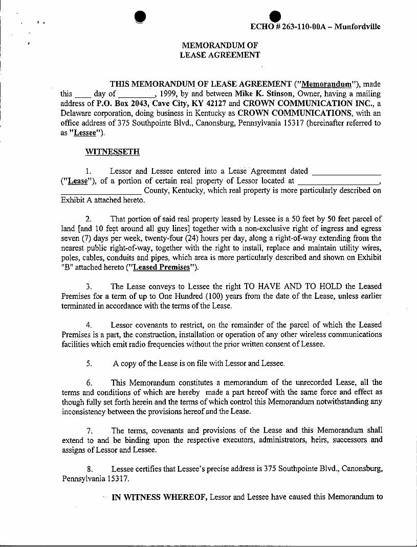
? r
c
0 ECHO ## 263-110-00A - Munfordville
MEMORANDUM OF LEASE AGREEMENT
THIS MEMORANDUM OF LEASE AGREEMENT ("Memorandum"), made this day of , 1999, by and between Mike K. Stinson, Owner, having a mailing address of P.O. Box 2043, Cave City, KY 42127 and CROWN COMMUNICATION INC., a Delaware corporation, doing business in Kentucky as CROWN COMMUNICATIONS, with an office address of 375 Southpointe Blvd., Canonsburg, Pennsylvania 153 17 (hereinafter referred to as "Lessee").
WITNESSETH
1. Lessor and Lessee entered into a Lease 'Agreement dated ("Lease"), of a portion of certain real property of Lessor located at
Exhibit A attached hereto.
Y
County, Kentucky, which real property is more particularly described on
2. That portion of said real property leased by Lessee is a 50 feet by 50 feet parcel of land [and 10 feet around all guy lines] together with a non-exclusive right of ingress and egress seven (7) days p'er week, twenty-four (24) hours per day, along a right-of-way extending from the nearest public right-of-way, together with the right to install, replace and maintain utility wires, poles, cables, conduits and pipes, which area is more particularly described and shown on Exhibit "B'l attached hereto ("Leased Premises").
3. The Lease conveys to Lessee the right TO HAVE AND TO HOLD the Leased Premises for a term of up to One Hundred (100) years from the date of the Lease, unless earlier terminated in accordance with the terms of the Lease.
4. Lessor covenants to restrict, on the remainder of the parcel of which the Leased Premises is a part, the construction, installation or operation of any other wireless communications facilities which emit radio frequencies without the prior written consent of Lessee.
5 . A copy of the Lease is on file with Lessor and Lessee.
6. This Memorandum constitutes a memorandum of the unrecorded Lease, all the terms and conditions of which are hereby made a part hereof with the same force and effect as though fully set forth herein and the terms of which control this Memorandum notwithstanding any inconsistency between the provisions hereof and the Lease.
7. The terms, covenants and provisions of the Lease and this Memorandum shall extend to and be binding upon the respective executors, administrators, heirs, successors and assigns of Lessor and Lessee.
8. Lessee certifies that Lessee's precise address is 375 Southpointe Blvd., Canonsburg, Pennsylvania 153 17.
- . IN WITNESS WHEREOF, Lessor and Lessee have caused this Memorandum to

be duly executed on the day and year first written above.
"LESSOR"
&?La+& 5z-L-L fiike K. Stinson
"LESSEE 'I CROWN COMMUNICATION INC., a Delaware corporation
By: John Binkley Vice President and General Manager
:- 2
L

P .. 0 I
COMMONWEALTH OF KENTUCKY )
COUNTY OF JEFFERSON) ) ss:
The foregoing instrument was subscribed, sworn to and acknowledged before me by 1 onthis >\ day of c t . b M - b < \ r ,1999.
u
1 r k u/ 3 Notary Public ’ \ -
My Commission expires: 03- \o ~ o 1
COMMONWEALTH OF Kentuclq 1
COUNTY OF Jefferson ) ) ss:
CORPORATE ACKNOWLEDGMENT
On this day of , 1999, before me, the subscriber, a Notary Public, in and for the Commonwealth of Pennsylvania, personally appeared John Binkley, Vice President and General Manager of Crown Communication Inc., a Delaware corporation, and in due form of law acknowledged that he is authorized on behalf of said corporation to execute all documents pertaining hereto and acknowledged to me that he executed the same as his voluntary act and deed on behalf of said corporation.
IN TESTIMONY WHERE, I have hereunto set my hand and affixed my seal in said County and Commonwealth as of the day and year last above written.
Notary Public
My Commission expires: PREPARED BY:
Norman W. Graham WYATT, TARRANT & COMBS 500 West Jefferson Street Louisville, KY 40202 (502) 589-5235
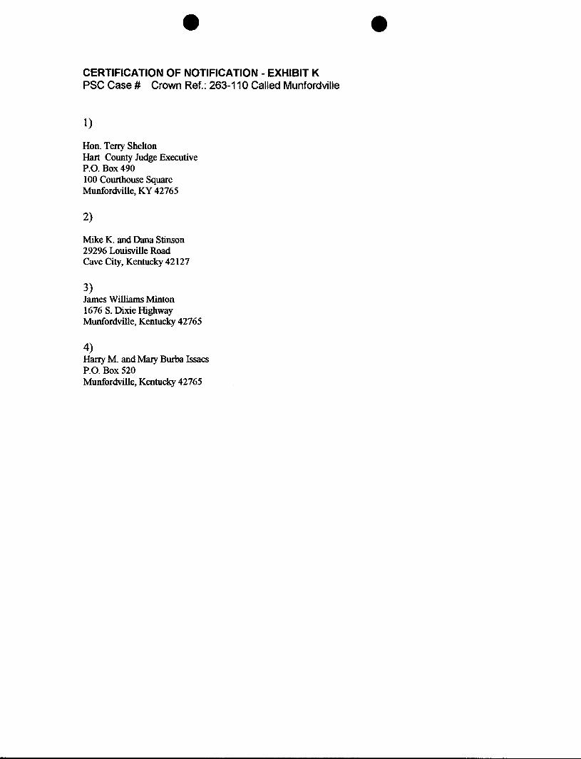
CERTIFICATION OF NOTIFICATION - EXHIBIT K PSC Case # Crown Ref.: 263-1 10 Called Munfordville
Hon. Terry Shelton Hart County Judge Executive P.O. Box 490 100 Courthouse Square Munfordville, KY 42765
Mike K. and Dana Stinson 29296 Louisville Road Cave City, Kentucky 42127
3) James Williams Minton 1676 S. Dixie Highway Mnfordville, Kentucky 42765
4) Harry M. and Mary Burba Issacs P.O. Box 520 Munfordville, Kentucky 42765
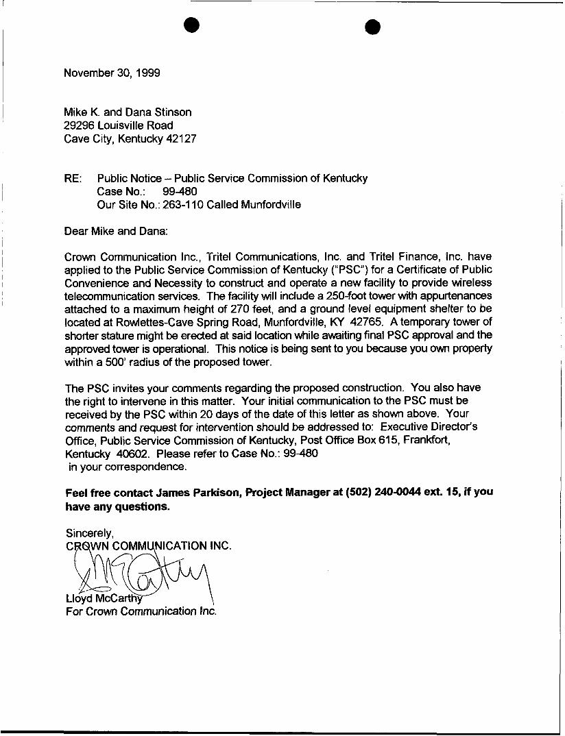
November 30, 1999
i Mike K. and Dana Stinson 29296 Louisville Road
I
I Cave City, Kentucky 42127
I RE: Public Notice - Public Service Commission of Kentucky ~
Case No.: 99480 Our Site No.: 263-1 10 Called Munfordville
Dear Mike and Dana:
Crown Communication Inc., Tritel Communications, Bnc. and Tritel Finance, Inc. have applied to the Public Service Commission of Kentucky (“PSC’I) for a Certificate of Public Convenience and Necessity to construct and operate a new facility to provide wireless telecommunication services. The facility will include a 250-foot tower with appurtenances attached to a maximum height of 270 feet, and a ground level equipment shelter to be located at Rowlettes-Cave Spring Road, Munfordville, KY 42765. A temporary tower of shorter stature might be erect4 at said location while awaiting final PSC approval and the approved tower is operational. This notice is being sent to you because you own property within a 500 radius of the proposed tower.
The PSC invites your comments regarding the proposed construction. You also have the right to intervene in this matter. Your initial communication to the PSC must be received by the PSC within 20 days of the date of this letter as shown above. Your comments and request for intervention should be addressed to: Executive Director‘s Office, Public Service Commission of Kentucky, Post Office Box 61 5, Frankfort, Kentucky 40602. Please refer to Case No.: 99480 in your correspondence.
Feel free contact James Parkison, Project Manager at (502) 240-0044 ext. 15, if you have any questions.
Sincerely, CRQWN COMMUNICATION INC.
Lloyd & 4 f McCarth
F O ~ Crown Communication inc.
November 30, 1999
James Williams Mint n 1676 S. Dixie Highway Munfordville, Kentucky 42765
RE: Public Notice - Public Service Commission of Kentucky Case No.: 99-480 Our Site No.: 263-1 10 Called Munfordville
Dear James:
Crown Communication Inc., Tritel Communications, Inc. and Tritel Finance, Inc. have applied to the Public Service Commission of Kentucky ("PSC") for a Certificate of Public Convenience and Necessity to construct and operate a new facility to provide wireless telecommunication services. The facility will include a 250-foot tower with appurtenances attached to a maximum height of 270 feet, and a ground level equipment shelter to be located at Rowlettes-Cave Spring Road, Munfordville, KY 42765. A temporary tower of shorter stature might be erected at said location while awaiting final PSC approval and the approved tower is operational. This notice is being sent to you because you own property within a 500 radius of the proposed tower.
The PSC invites your comments regarding the proposed construction. You also have the right to intervene in this matter. Your initial communication to the PSC must be received by the PSC within 20 days of the date of this letter as shown above. Your comments and request for intervention should be addressed to: Executive Director's Office, Public Service Commission of Kentucky, Post Office Box 61 5, Frankfort, Kentucky 40602. Please refer to Case No.: 99-480 in your correspondence.
Feel free contact James Parkison, Project Manager at (502) 240-0044 ext. 15, if you have any questions.
Sincerely, C WN COMMUNI ATION INC. b e
J Lldyd McCarthy L
For Crown Communication Inc.

November 30, 1999
Harry M. and Mary Bul‘ba lssacs P.O. Box520 Munfordvi I le, Kentucky 42765
RE: Public Notice - Public Service Commission of Kentucky Case No.: 99-480 Our Site No.: 263-1 10 Called Munfordville
Dear Harry and Mary:
Crown Communication Inc., Tritel Communications, Inc. and Tritel Finance, Inc. have applied to the Public Service Commission of Kentucky (“PSC”) for a Certificate of Public Convenience and Necessity to construct and operate a new facility to provide wireless telecommunication services. The facility will include a 250-foot tower with appurtenances attached to a maximum height of 270 feet, and a ground level equipment shelter to be located at Rowfettes-Cave Spring Road, Munfordville, KY 42765. A temporary tower of shorter stature might be erected at said location while awaiting final PSC approval and the approved tower is operational. This notice is being sent to you because you own property within a 500’ radius of the proposed tower.
The PSC invites your comments regarding the proposed construction. You also have the right to intervene in this matter. Your initial communication to the PSC must be received by the PSC within 20 days of the date of this letter as shown above. Your comments and request for intervention should be addressed to: Executive Director‘s Office, Public Service Commission of Kentucky, Post Office Box 61 5, Frankfort, Kentucky 40602. Please refer to Case No.: 99480 in your correspondence.
Feel free contact James Parkison, Project Manager at (502) 240-0044 ext. 15, if you have any questions.
Sincerely,

November 30, 1999
Hon. Terry Shelton Hart County Judge Executive P.O. Box490 100 Courthouse Square Munfordville, KY 42765
RE: Public Notice - Public Service Commission of Kentucky Case No.: 99-480 Our Site No.: 263-1 10 Called Munfordville
Honorable Judge Shelton:
Crown Communication Inc., Tritel Communications, Inc. and Tritel Finance, Inc. have applied to the Public Service Commission of Kentucky (“PSC”) for a Certificate of Public Convenience and Necessity to construct and operate a new facility to provide wireless telecommunication services. The facility will include a 250-foot tower with appurtenances attached to a maximum height of 270 feet, and a ground level equipment shelter to be located at Rowlettes-Cave Spring Road, Munfordville, KY 42765. A temporary tower of shorter stature might be erected at said location while awaiting final PSC approval and the approved tower is operational. This notice is being sent to you because you are the Judge Executive of Hart County.
The PSC invites your comments regarding the proposed construction. You also have the right to intervene in this matter. Your initial communication to the PSC must be received by the PSC within 20 days of the date of this letter as shown above. Your comments and request for intervention should be addressed to: Executive Director‘s Office, Public Service Commission of Kentucky, Post Office Box 615, Frankfort, Kentucky 40602. Please refer to Case No.: 99-480 in your correspondence.
Feel free contact James Parkison, Project Manager at (502) 2404044 ext. 15, if you have any questions.
Sincerely, C
Ll For Crown Communicatjon Inc. ’

EXHIBIT N COPY OF POSTING NOTICES
29
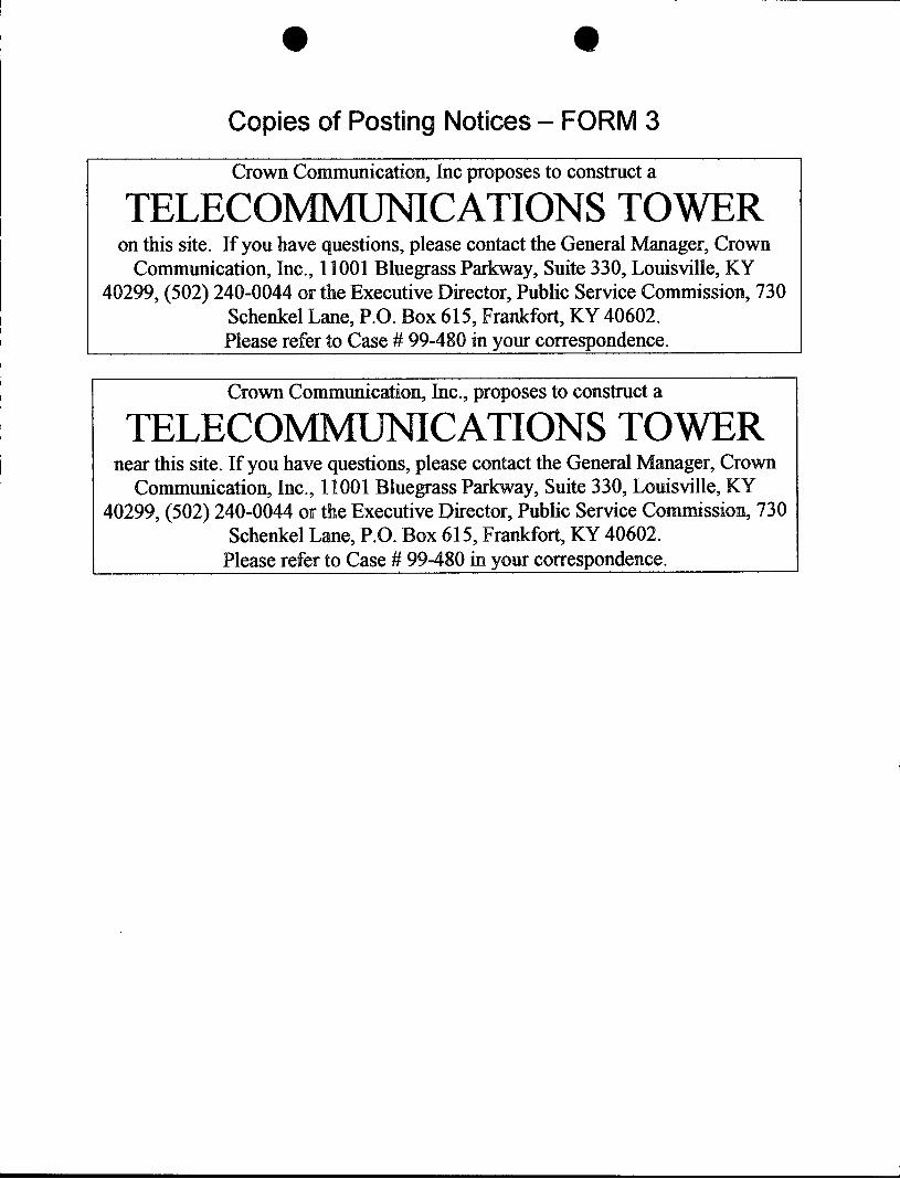
e 8
Copies of Posting Notices - FORM 3
I I
I Crown Communication, Inc proposes to construct a
Schenkel Lane, P.O. Box 615, FrMort , MY 40602. Please refer to Case # 99-480 in your correspondence.
1 TELECOMMUNI CATIONS TOWER
I
I
on this site. If you have questions, please contact the General Manager, Crown Communication, Inc., 11001 Bluegrass Parkway, Suite 330, Louisville, KY
40299, (502) 240-0044 or the Executive Director, Public Service Commission, 730
Crown Communication, Inc., proposes to construct a
near this site. If you have questions, please contact the General Manager, Crown TELECO CATIONS TOWER Communication, Inc., 1 BOO1 Bluegrass Parkway, Suite 330, Louisville, KY
40299, (502) 240-0044 or the Executive Director, Public Service C O ~ S S ~ O D , 730 Schenkel Lane, P.O. Box 615, Frankfort, KY 40602.
Please refer to Case # 99-480 in your correspondence.
EXHIBIT 0 COPY OF RADIO FREQUENCY DESIGN SEARCH AREA
30

Coverage Objectives
FAA Height Restriction NIA AM Tower Concern? No
M5 and US31 between Munfordville and Horse Cave
A B. C. ,o.
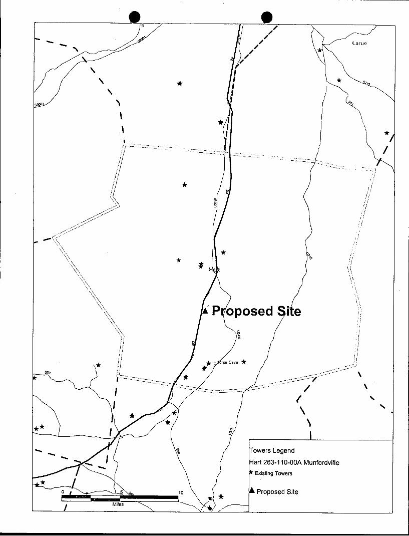
b 4
\ f
I
\ \
art 263-1 IO-OOA Munfordville
EXHIBIT P TOWER MAP FOR SUBJECT COUNTY
31


