BULETINUL INSTITUTULUI POLITEHNIC DIN IAŞI Publicat de Universitatea Tehnică „Gheorghe Asachi” din Iaşi Tomul LXI (LXV), Fasc. 3, 2015 Secţia CONSTRUCŢII. ARHITECTURĂ NUMERICAL ANALYSIS OF A STEEL WIRE MESH SEISMIC RETROFITTING TECHNIQUES FOR MASONRY STRUCTURES BY ADRIAN IOAN DOGARIU * Politehica University Timişoara Civil Engineering Faculty Received: July 17, 2015 Accepted for publication: July 31, 2015 Abstract. This article will present the experimental activities and numerical analysis of an intervention technique efficiency. This technique applies a stainless or zinc coated steel wire mesh (SWM) bonded with epoxy resin to the masonry walls, on one or both sides. Important advantage of this technique may be related to its reversibility - wire mesh fixed with epoxy resin can be removed from the masonry wall by heating the resin layer. Steel wire mesh reinforced masonry walls have a complex behaviour and no analytic procedures for design are available; therefore, advanced numerical models confirmed by extended experimental tests are need. The experimental program is presented together with the finite element model adopted for retrofitted masonry specimens. The numerical model is calibrated according to the contact-less and full-field measurements. The experimental tests, carried-out within the framework of a European research project, have included tests on steel wires, on steel meshes, on 500 by 500 mm retrofitted masonry elements (diagonal tensile tests) and 1500 by 1500 mm masonry walls. The numerical calibration have been made using ABAQUS finite element software. The replacing of simple masonry with an equivalent material with improved behaviour, can be done following the experimental testing results. This kind of approach that considers the retrofitting steel wire mesh as an external reinforcing can really simplify the numerical effort. * Corresponding author: e-mail: [email protected]
Transcript
BULETINUL INSTITUTULUI POLITEHNIC DIN IAŞI Publicat de
Universitatea Tehnică „Gheorghe Asachi” din Iaşi Tomul LXI (LXV), Fasc. 3, 2015
Secţia CONSTRUCŢII. ARHITECTURĂ
NUMERICAL ANALYSIS OF A STEEL WIRE MESH SEISMIC RETROFITTING TECHNIQUES FOR MASONRY STRUCTURES
BY
ADRIAN IOAN DOGARIU*
Politehica University Timişoara
Civil Engineering Faculty
Received: July 17, 2015 Accepted for publication: July 31, 2015
Abstract. This article will present the experimental activities and numerical
analysis of an intervention technique efficiency. This technique applies a stainless or zinc coated steel wire mesh (SWM) bonded with epoxy resin to the masonry walls, on one or both sides. Important advantage of this technique may be related to its reversibility - wire mesh fixed with epoxy resin can be removed from the masonry wall by heating the resin layer. Steel wire mesh reinforced masonry walls have a complex behaviour and no analytic procedures for design are available; therefore, advanced numerical models confirmed by extended experimental tests are need. The experimental program is presented together with the finite element model adopted for retrofitted masonry specimens. The numerical model is calibrated according to the contact-less and full-field measurements. The experimental tests, carried-out within the framework of a European research project, have included tests on steel wires, on steel meshes, on 500 by 500 mm retrofitted masonry elements (diagonal tensile tests) and 1500 by 1500 mm masonry walls. The numerical calibration have been made using ABAQUS finite element software. The replacing of simple masonry with an equivalent material with improved behaviour, can be done following the experimental testing results. This kind of approach that considers the retrofitting steel wire mesh as an external reinforcing can really simplify the numerical effort.
1.1. Masonry Behaviour and Anti-Seismic Retrofitting Technique
Masonry material is one of the most wildly use material for construction of buildings in most part of the world. Brick masonry structures employing solid clay units and cement-mortar can be found in many urban and rural areas of Romania. Romanian territory is subjected to frequent earthquakes that induce shear stresses in the structural walls.
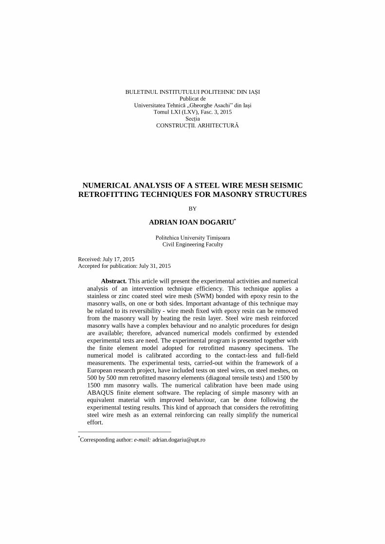
Many masonry buildings, located in prone seismic areas, present a high seismic vulnerability and require structural interventions. Retrofitting solutions which will increase capacity and ductility of the elements, without a major influence on its stiffness is valuable. Such a technique (Dogariu, 2009), investigated within the framework of FP6 EU PROHITECH, applies a stainless or zinc coated steel wire mesh bonded with epoxy resin to the masonry walls (Fig. 1), on one or both sides.
Fig. 1 – Retrofitting solution based on epoxy-glued steel wire
mesh (SWM).
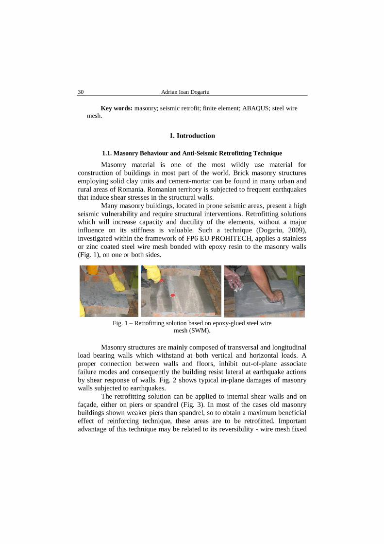
Masonry structures are mainly composed of transversal and longitudinal load bearing walls which withstand at both vertical and horizontal loads. A proper connection between walls and floors, inhibit out-of-plane associate failure modes and consequently the building resist lateral at earthquake actions by shear response of walls. Fig. 2 shows typical in-plane damages of masonry walls subjected to earthquakes.
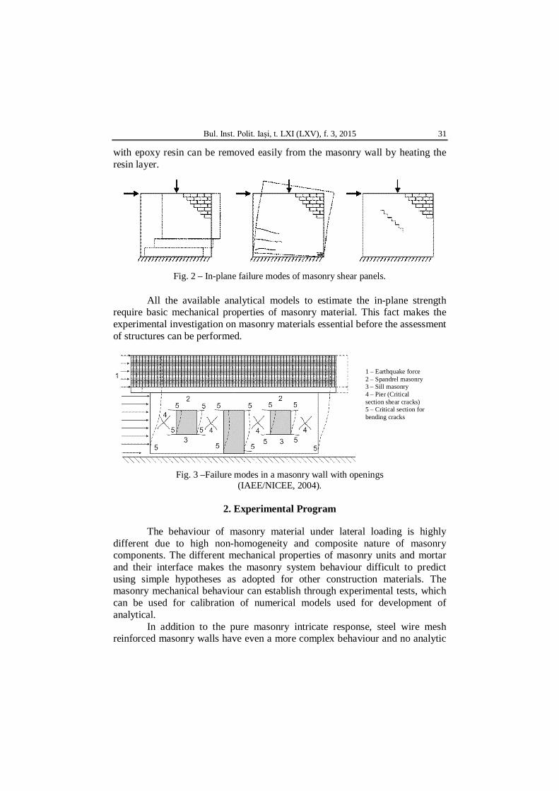
The retrofitting solution can be applied to internal shear walls and on façade, either on piers or spandrel (Fig. 3). In most of the cases old masonry buildings shown weaker piers than spandrel, so to obtain a maximum beneficial effect of reinforcing technique, these areas are to be retrofitted. Important advantage of this technique may be related to its reversibility - wire mesh fixed
Bul. Inst. Polit. Iaşi, t. LXI (LXV), f. 3, 2015 31
with epoxy resin can be removed easily from the masonry wall by heating the resin layer.
Fig. 2 – In-plane failure modes of masonry shear panels.
All the available analytical models to estimate the in-plane strength
require basic mechanical properties of masonry material. This fact makes the experimental investigation on masonry materials essential before the assessment of structures can be performed.
Fig. 3 –Failure modes in a masonry wall with openings (IAEE/NICEE, 2004).
2. Experimental Program
The behaviour of masonry material under lateral loading is highly
different due to high non-homogeneity and composite nature of masonry components. The different mechanical properties of masonry units and mortar and their interface makes the masonry system behaviour difficult to predict using simple hypotheses as adopted for other construction materials. The masonry mechanical behaviour can establish through experimental tests, which can be used for calibration of numerical models used for development of analytical.
In addition to the pure masonry intricate response, steel wire mesh reinforced masonry walls have even a more complex behaviour and no analytic
32 Adrian Ioan Dogariu
procedures for design are available; therefore, advanced numerical models confirmed by extended experimental tests are need. Is briefly presented the experimental program, carried out at Politehnica University Timisoara in the CESMAST laboratory. Mechanical characterization of a highly inhomogeneous material composed by solid clay-brick masonry glued by means of epoxy resin with steel wire layer material was aimed.
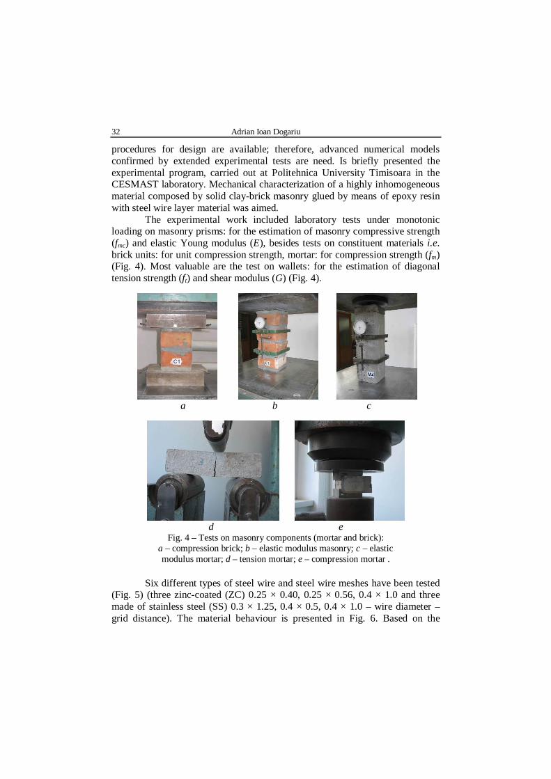
The experimental work included laboratory tests under monotonic loading on masonry prisms: for the estimation of masonry compressive strength (fmc) and elastic Young modulus (E), besides tests on constituent materials i.e. brick units: for unit compression strength, mortar: for compression strength (fm) (Fig. 4). Most valuable are the test on wallets: for the estimation of diagonal tension strength (ft) and shear modulus (G) (Fig. 4).
a b c
d e
Fig. 4 – Tests on masonry components (mortar and brick): a – compression brick; b – elastic modulus masonry; c – elastic modulus mortar; d – tension mortar; e – compression mortar .
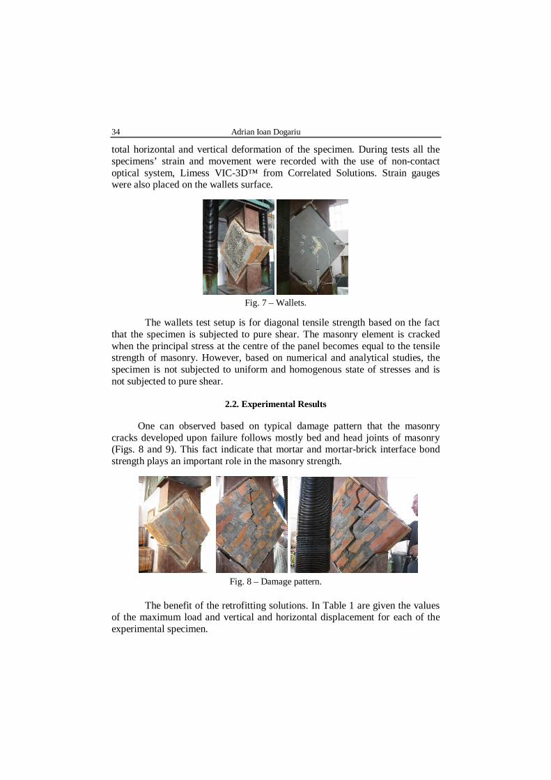
Six different types of steel wire and steel wire meshes have been tested
(Fig. 5) (three zinc-coated (ZC) 0.25 × 0.40, 0.25 × 0.56, 0.4 × 1.0 and three made of stainless steel (SS) 0.3 × 1.25, 0.4 × 0.5, 0.4 × 1.0 – wire diameter – grid distance). The material behaviour is presented in Fig. 6. Based on the
Bul. Inst. Polit. Iaşi, t. LXI (LXV), f. 3, 2015 33
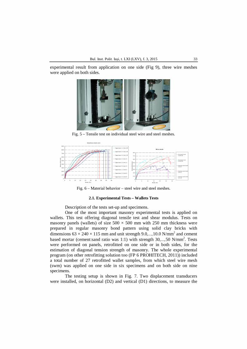
experimental result from application on one side (Fig 9), three wire meshes were applied on both sides.
Fig. 5 – Tensile test on individual steel wire and steel meshes.
Stainless steel wire
0
100
200
300
400
500
600
700
800
900
0 5 10 15 20 25 30 35 40 45
Strain (%)
Str
ess
(N/m
m2)
Specimen 1 0.3x1.25
Specimen 2 0.3x1.25
Specimen 3 0.3x1.25
Specimen 1 0.4x1.0
Specimen 2 0.4x1.0
Specimen 3 0.4x1.0
Specimen 1 0.4x0.5
Specimen 2 0.4x0.5
Specimen 3 0.4x0.5
Wire mesh
0
100
200
300
400
500
600
700
800
0 5 10 15 20 25 30
Strain (%)
Str
ess
(N
/mm
2)
Zincoated mesh0.25x0.40
Zincoated mesh0.25x0.56
Stainless steel mesh0.4x0.5
Stainless steel mesh0.4x1.0
Stainless steel mesh0.x1.25
Fig. 6 – Material behavior – steel wire and steel meshes.
2.1. Experimental Tests – Wallets Tests
Description of the tests set-up and specimens. One of the most important masonry experimental tests is applied on
wallets. This test offering diagonal tensile test and shear modulus. Tests on masonry panels (wallets) of size 500 × 500 mm with 250 mm thickness were prepared in regular masonry bond pattern using solid clay bricks with dimensions 63 × 240 × 115 mm and unit strength 9.010.0 N/mm2 and cement based mortar (cement:sand ratio was 1:1) with strength 3050 N/mm2. Tests were performed on panels, retrofitted on one side or in both sides, for the estimation of diagonal tension strength of masonry. The whole experimental program (on other retrofitting solution too (FP 6 PROHITECH, 2011)) included a total number of 27 retrofitted wallet samples, from which steel wire mesh (swm) was applied on one side in six specimens and on both side on nine specimens.
The testing setup is shown in Fig. 7. Two displacement transducers were installed, on horizontal (D2) and vertical (D1) directions, to measure the
34 Adrian Ioan Dogariu
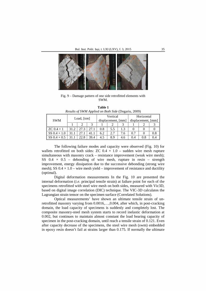
total horizontal and vertical deformation of the specimen. During tests all the specimens’ strain and movement were recorded with the use of non-contact optical system, Limess VIC-3D™ from Correlated Solutions. Strain gauges were also placed on the wallets surface.
Fig. 7 – Wallets.
The wallets test setup is for diagonal tensile strength based on the fact
that the specimen is subjected to pure shear. The masonry element is cracked when the principal stress at the centre of the panel becomes equal to the tensile strength of masonry. However, based on numerical and analytical studies, the specimen is not subjected to uniform and homogenous state of stresses and is not subjected to pure shear.
2.2. Experimental Results
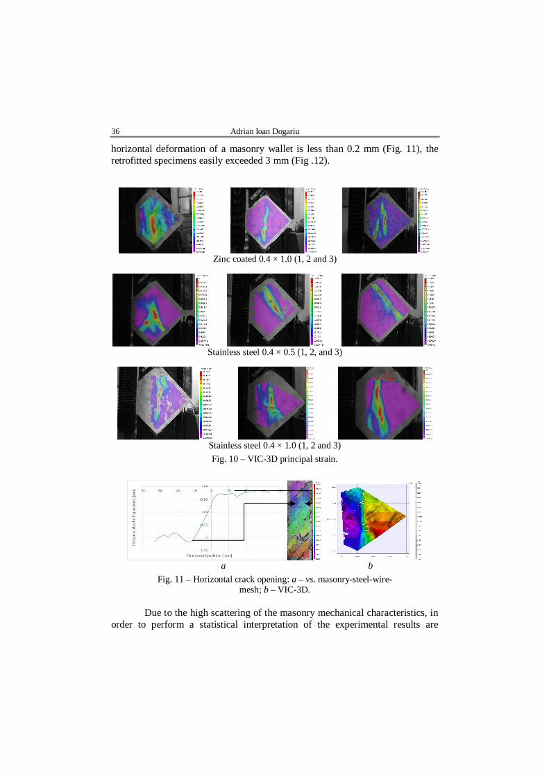
One can observed based on typical damage pattern that the masonry
cracks developed upon failure follows mostly bed and head joints of masonry (Figs. 8 and 9). This fact indicate that mortar and mortar-brick interface bond strength plays an important role in the masonry strength.
Fig. 8 – Damage pattern.
The benefit of the retrofitting solutions. In Table 1 are given the values
of the maximum load and vertical and horizontal displacement for each of the experimental specimen.
Bul. Inst. Polit. Iaşi, t. LXI (LXV), f. 3, 2015 35
Fig. 9 – Damage pattern of one side retrofitted elements with SWM.
Table 1 Results of SWM Applied on Both Side (Dogariu, 2009)
The following failure modes and capacity were observed (Fig. 10) for
wallets retrofitted on both sides: ZC 0.4 × 1.0 – sudden wire mesh rupture simultaneous with masonry crack – resistance improvement (weak wire mesh); SS 0.4 × 0.5 – debonding of wire mesh, rupture in resin – strength improvement, energy dissipation due to the successive debonding (strong wire mesh); SS 0.4 × 1.0 – wire mesh yield – improvement of resistance and ductility (optimal).
Digital deformation measurements In the Fig. 10 are presented the internal deformation (i.e. principal tensile strain) at failure point for each of the specimens retrofitted with steel wire mesh on both sides, measured with Vic3D, based on digital image correlation (DIC) technique. The VIC-3D calculates the Lagrangian strain tensor on the specimen surface (Correlated Solutions).
Optical measurements’ have shown an ultimate tensile strain of un-retrofitted masonry varying from 0.0016,…,0.004, after which, in post-cracking domain, the load capacity of specimens is suddenly and completely lost. The composite masonry-steel mesh system starts to record inelastic deformation at 0.002, but continues to maintain almost constant the load bearing capacity of specimen in the post-cracking domain, until reach a tensile strain of 0.121. Even after capacity decrease of the specimens, the steel wire mesh (swm) embedded in epoxy resin doesn’t fail at strains larger than 0.175. If normally the ultimate
36 Adrian Ioan Dogariu
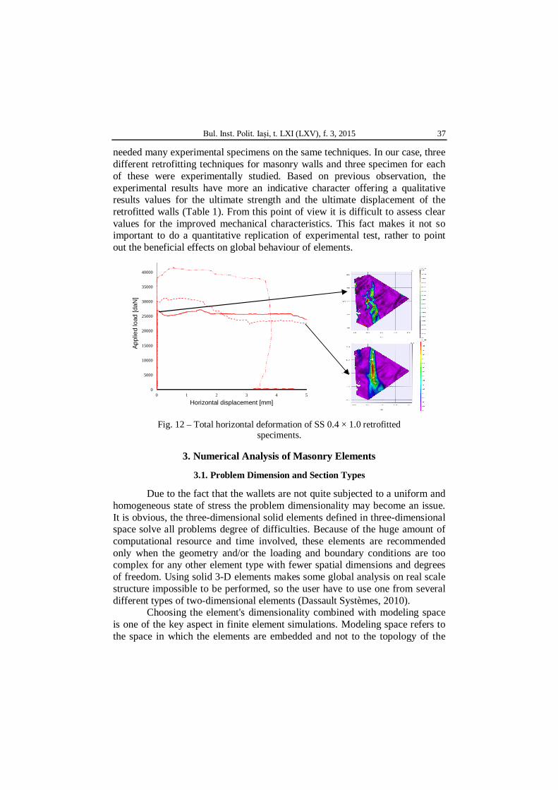
horizontal deformation of a masonry wallet is less than 0.2 mm (Fig. 11), the retrofitted specimens easily exceeded 3 mm (Fig .12).
Zinc coated 0.4 × 1.0 (1, 2 and 3)
Stainless steel 0.4 × 0.5 (1, 2, and 3)
Stainless steel 0.4 × 1.0 (1, 2 and 3) Fig. 10 – VIC-3D principal strain.
a b
Fig. 11 – Horizontal crack opening: a – vs. masonry-steel-wire-mesh; b – VIC-3D.
Due to the high scattering of the masonry mechanical characteristics, in
order to perform a statistical interpretation of the experimental results are
Bul. Inst. Polit. Iaşi, t. LXI (LXV), f. 3, 2015 37
needed many experimental specimens on the same techniques. In our case, three different retrofitting techniques for masonry walls and three specimen for each of these were experimentally studied. Based on previous observation, the experimental results have more an indicative character offering a qualitative results values for the ultimate strength and the ultimate displacement of the retrofitted walls (Table 1). From this point of view it is difficult to assess clear values for the improved mechanical characteristics. This fact makes it not so important to do a quantitative replication of experimental test, rather to point out the beneficial effects on global behaviour of elements.
0
5000
10000
15000
20000
25000
30000
35000
40000
0 1 2 3 4 5
Appl
ied
load
[daN
]
Horizontal displacement [mm]
Fig. 12 – Total horizontal deformation of SS 0.4 × 1.0 retrofitted
speciments.
3. Numerical Analysis of Masonry Elements
3.1. Problem Dimension and Section Types
Due to the fact that the wallets are not quite subjected to a uniform and homogeneous state of stress the problem dimensionality may become an issue. It is obvious, the three-dimensional solid elements defined in three-dimensional space solve all problems degree of difficulties. Because of the huge amount of computational resource and time involved, these elements are recommended only when the geometry and/or the loading and boundary conditions are too complex for any other element type with fewer spatial dimensions and degrees of freedom. Using solid 3-D elements makes some global analysis on real scale structure impossible to be performed, so the user have to use one from several different types of two-dimensional elements (Dassault Systèmes, 2010).
Choosing the element's dimensionality combined with modeling space is one of the key aspect in finite element simulations. Modeling space refers to the space in which the elements are embedded and not to the topology of the
38 Adrian Ioan Dogariu
element. For entire structures with transversal and longitudinal walls a three-dimensional element must be used. In many cases, similar to the hand calculation approaches, the masonry buildings can be divided in planar shear walls and only a façade or internal wall could be model with a two-dimensional planar part using two-dimensional solid continuum elements. Are included plane stress elements and plane strain elements.
Material properties for masonry elements are obtained on solid elements with comparable size on all directions. The transition from 3d calibrated models to 2d models could introduce inherent differences due to the change in states of stress. For this reason 3-D Shell elements are preferred for this study.
Solid sections includes the material type and, if the section is to be associated to a two-dimensional region, the section thickness must be specified by a plane stress or plane strain thickness. For a shell sections one must define the thickness, material type. Many commercial finite elements software (Dassault Systèmes, 2010) includes a special type of shell section, i.e. the composite shell sections. Composite shell sections consist of layers of materials, a section Poisson's ratio, and optional rebar layers.
3.2. Modeling Issues
Few commercial finite element software have in their material library defined masonry materials behaviour laws. During the last forty years, an enormous growth in the development of numerical tools for structural analysis has been achieved. Nowadays, the finite element method is usually adopted in order to achieve sophisticated simulations of the structural behaviour. A description of the material behaviour, which yields the relation between the stress and strain tensor in a material point of the body, is necessary for this purpose. This mathematical description is commonly named a constitutive model and an important objective of today’s research is to obtain robust numerical tools, capable of predicting the behaviour of the structure from the elastic domain until total failure, due to excessive cracking and rigidity degradation.
Discontinuous modeling of masonry - Lately, a considerable attention has been given to rational assessment methodologies, to be directly consistent with the discontinuous nature of structural masonry.
The discontinuities in continuous systems are in fact interfaces between dissimilar materials and joints or fractures in the material. A survey of the literature (Tzamtzis, 2003) on finite element modeling of cracks and joints shows that three main approaches are common for a representative analysis: the discrete crack and the smeared crack approach or the use of joint or interface elements.
Bul. Inst. Polit. Iaşi, t. LXI (LXV), f. 3, 2015 39
Discrete crack approach represents the crack as a separation of nodes. When the stress or strain at a node, or the average in adjacent elements, exceeds a given value, the node is redefined as two nodes and the elements on either side are allowed to separate increasing the number of equations to be solved and extends the bandwidth of the stiffness matrix.
In the smeared crack approach, cracks and joints are modeled in an average sense by an appropriate modification of the material properties at the integration points of regular finite elements.
Smeared cracks are convenient when the crack orientations are not known beforehand, because the formation of a crack involves no re-meshing or new degrees of freedom. However, they have only limited ability to model sharp discontinuities and represent the topology or material behaviour in the vicinity of the crack.
The method is attractive if global analysis of large-scale masonry structures is required. It does not make a distinction between individual bricks and joints, but treats masonry as an anisotropic composite such that joints and cracks are smeared out. An inherent limitation of the smeared crack approach is that discrete cracks are smeared out over an entire element and the crack opening is modeled by the continuous displacement approximation functions of the conventional finite element approach. In view of this limitation, as well as other problems such as mesh-dependency due to tensile and compressive softening and difficulties of model calibration, smeared crack models should only be used with caution for the analysis of discontinuous structures.
The Interface smeared crack approach combines the advantages of the discrete and smeared approaches described above, treating cracks discretely like joint elements, but, like smeared crack elements.
Most of the crack models available have only limited ability to model sharp discontinuities present in many structural systems.
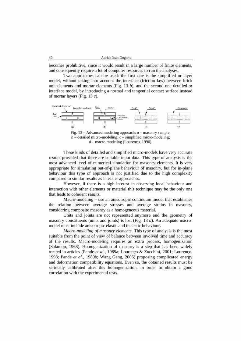
Continuous modeling of masonry. The first step toward carrying out such analyses is to develop adequate constitutive models. In the case of masonry (Fig. 13 a), when using the continuum model approach, three levels of approximation might be applied: micro-models, simplified or detailed, and macro-models (Rots, 1991):
Micro-modeling – when units are represented by continuum elements whereas the behaviour of the mortar joints and unit-mortar interface is lumped in discontinuous or interface elements. A complete micro-model must include all the failure mechanisms of masonry, namely, cracking of joints, sliding over one head or bed joint, cracking of the units and crushing of masonry.
In the micro-model, each component of masonry – unit, mortar (simplified), and unit/mortar joint (detailed) – must be represented by different finite elements. The employment of a micro-model to analyse an entire building
40 Adrian Ioan Dogariu
becomes prohibitive, since it would result in a large number of finite elements, and consequently require a lot of computer resources to run the analyses.
Two approaches can be used: the first one is the simplified or layer model, without taking into account the interface (friction law) between brick unit elements and mortar elements (Fig. 13 b), and the second one detailed or interface model, by introducing a normal and tangential contact surface instead of mortar layers (Fig. 13 c).
Fig. 13 – Advanced modeling approach: a – masonry sample; b – detailed micro-modeling; c – simplified micro-modeling;
d – macro-modeling (Lourenço, 1996).
These kinds of detailed and simplified micro-models have very accurate results provided that there are suitable input data. This type of analysis is the most advanced level of numerical simulation for masonry elements. It is very appropriate for simulating out-of-plane behaviour of masonry, but for in-plane behaviour this type of approach is not justified due to the high complexity compared to similar results as in easier approaches.
However, if there is a high interest in observing local behaviour and interaction with other elements or material this technique may be the only one that leads to coherent results.
Macro-modeling – use an anisotropic continuum model that establishes the relation between average stresses and average strains in masonry, considering composite masonry as a homogeneous material.
Units and joints are not represented anymore and the geometry of masonry constituents (units and joints) is lost (Fig. 13 d). An adequate macro-model must include anisotropic elastic and inelastic behaviour.
Macro-modeling of masonry elements. This type of analysis is the most suitable from the point of view of balance between involved time and accuracy of the results. Macro-modeling requires an extra process, homogenization (Salamon, 1968). Homogenization of masonry is a step that has been widely treated in articles (Pande et al., 1989a; Lourenço & Zucchini, 2001; Lourenço, 1998; Pande et al., 1989b; Wang Gang, 2006) proposing complicated energy and deformation compatibility equations. Even so, the obtained results must be seriously calibrated after this homogenization, in order to obtain a good correlation with the experimental tests.
Bul. Inst. Polit. Iaşi, t. LXI (LXV), f. 3, 2015 41
The most convenient approach is to use o macro-model in which the material behaviour characteristic parameters to be borrowed from concrete models.
Because of the non-symmetrical behaviour in tension and compression, typically for a concrete material calibration at least uniaxial compression and uniaxial tension experimental tests are needed. Default values which consider the bi-axial behaviour of concrete are available in the scientific literature (Dassault Systèmes, 2010) based on large experimental campaigns. If an accurate post-failure/cracking behaviour is desired than other experiments may be required. Unlike concrete elements, due to their inherent inhomogeneous character masonry pose an anisotropic behaviour. At least theoretically the material mechanical properties should be defined taking into account their directionally dependent character.
The uniaxial compression test consist in compressing the material specimen. By recording the load and displacement, applying simple formulas one can extract the stress-strain curve. Uniaxial tension test is much more difficult to perform and only the pre-failure response can be obtain with enough confidence even for mortar specimens. In case of masonry specimens this kind of test is not available, and one can make only assumption about the tensile failure strength of the masonry material. The scientific literature recommends a value of 7%,…,10% of the compressive strength. The choice of tensile cracking stress is very important, because in almost all cases the failure mode is govern by tensile behaviour. Use of low cracking stresses will cause numerical problems.
In case of brittle material, calibration of the post-cracking behaviour depend on the reinforcement present. For masonry behaviour law, a stress-displacement tension stiffening model is recommended with typical values less than 0.05 mm. In case of reinforced masonry, if the reinforcing layer is strong enough, the stress-strain tension stiffening model is more appropriate. For numerical models with an acceptable mesh network could be assumed that the strain softening after cracking brings the stress to zero at a total strain 10 times the strain at failure. This results a zero stress at a total strain of about 0,001 or less (Dassault Systèmes, 2010).
To understand the post-cracking shear behaviour combined tension and shear experiments are used. Unfortunately these experiments are quite difficult to perform. Without experimental results one may assume with a good confidence that the shear retention factor goes linearly to zero at the same crack opening strain used for the tension stiffening model.
For defining the failure ratios which gives the biaxial yield and flow parameters biaxial experiments are required to calibrate (Dhanasekar, 1985; Page, 1981).
42 Adrian Ioan Dogariu
High scattering of the masonry mechanical characteristics, impose for the statistical interpretation of the experimental results many experimental specimens on the same techniques. In our case were experimentally study three different techniques for masonry walls retrofitting and only three specimen for each of these. On this observation, the experimental results have more a qualitative values offering an indicative results values for the strength and displacement characteristics of the retrofitted walls.
Concrete smeared cracking model. This materials uses oriented damaged elasticity concepts (smeared cracking) to describe the reversible part of the material's response after cracking failure (Dassault Systèmes, 2010).
The concrete smeared cracking model was made for defining plain concrete elements (beams, trusses, shells, and solids) behaviour for monotonic loadings under low confining pressures with small consideration of the confining effect. The material use an isotropic hardening yield surface active when the stress is mainly compressive.
This material law assumes that cracking is the most important aspect of the behaviour of such a relatively brittle material, and representation of cracking and post-cracking behaviour prevail the model. An independent “crack detection surface” that determines if a point fails by cracking.
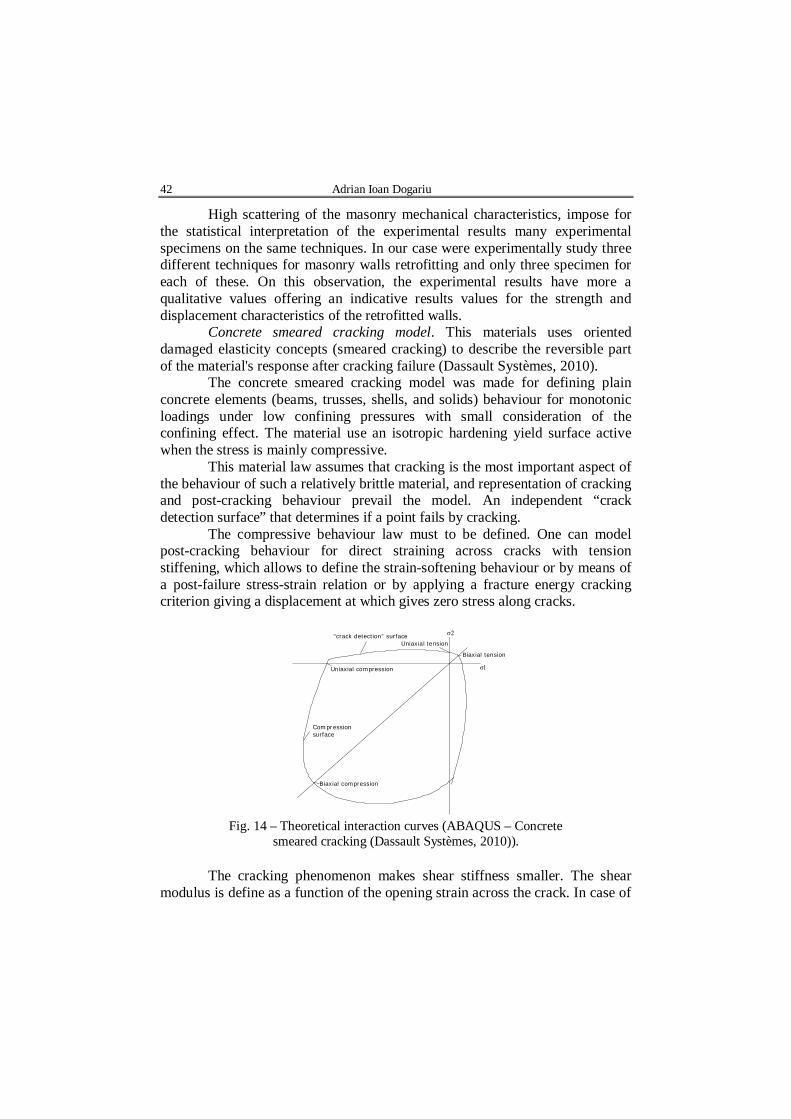
The compressive behaviour law must to be defined. One can model post-cracking behaviour for direct straining across cracks with tension stiffening, which allows to define the strain-softening behaviour or by means of a post-failure stress-strain relation or by applying a fracture energy cracking criterion giving a displacement at which gives zero stress along cracks.
The cracking phenomenon makes shear stiffness smaller. The shear modulus is define as a function of the opening strain across the crack. In case of
Bul. Inst. Polit. Iaşi, t. LXI (LXV), f. 3, 2015 43
wallets specimens the overall response is not strongly dependent on the amount of shear retention.
The shape of the failure surface (Fig. 14) is defined by means of four values (Dassault Systèmes, 2010): Ratio of the ultimate biaxial compressive stress to the uniaxial compressive ultimate stress – 1.16; Absolute value of the ratio of uniaxial tensile stress at failure to the uniaxial compressive stress at failure – 0.625; Ratio of the magnitude of a principal component of plastic strain at ultimate stress in biaxial compression to the plastic strain at ultimate stress in uniaxial compression – 1.28; Ratio of the tensile principal stress value at cracking in plane stress, when the other nonzero principal stress component is at the ultimate compressive stress value, to the tensile cracking stress under uniaxial tension – 0.33.
3. Numerical Results and Conclusions In present study a macro-model approach was adopted. Due to very
complex mathematical procedure and experimental results need for the homogenisation process, the finite element model from this article used the masonry material properties, i.e. tensile strength (ftm = 0.45 MPa) and compressive strength (fcm = 7.5 MPa), taken from the wallets tests.
A 3-D Shell element was chosen in order to reduce the computational effort and time and, more important, to be adequate for large models resulting in modeling real structures. Also a 3-D Solid based model was built for validate the shell finite element model.
The concrete smeared cracking was used for both masonry (mas) and complex masonry-steel wire mesh (mas-swm) materials. Many empirical equations are suggested in scientific literature and design standards as constitutive laws for masonry elements as a homogenous material, subjected to compressive loading normal to the bed joints. Due to the fact that principal tensile stresses cause cracking and failure of the specimens, a very simple rectangular law was used for uniaxial compression behaviour (elastic – perfect plastic). The following properties have been defined k = 7.5 MPa maximum allowable compression strength.
The only difference introduce at the definition of the two materials (i.e. mas and mas-swm) is the value for the tension stiffening. Even if for the complex mas-swm material a strain type definition could be more appropriate, for the sake of simplicity, for both cases the tension stiffening was define in terms of displacement, i.e. 0.2 mm for masonry and 3 mm for complex masonry-steel mesh material.
The mesh technique was structured, consisting in an 8 by 8 finite element square network, using 64 linear quadrilateral elements of type S4R (Dassault Systèmes, 2010).
44 Adrian Ioan Dogariu
In terms of global behaviour the masonry elements shown a sudden failure after reaching the maximum crack width. In case of retrofitted elements an important increase of capacity from approximate 16 t around 30 t. For retrofitted element after reaching the maximum force and important “inelastic plateaux” was observed and a major increase of crack opening have been obtained.
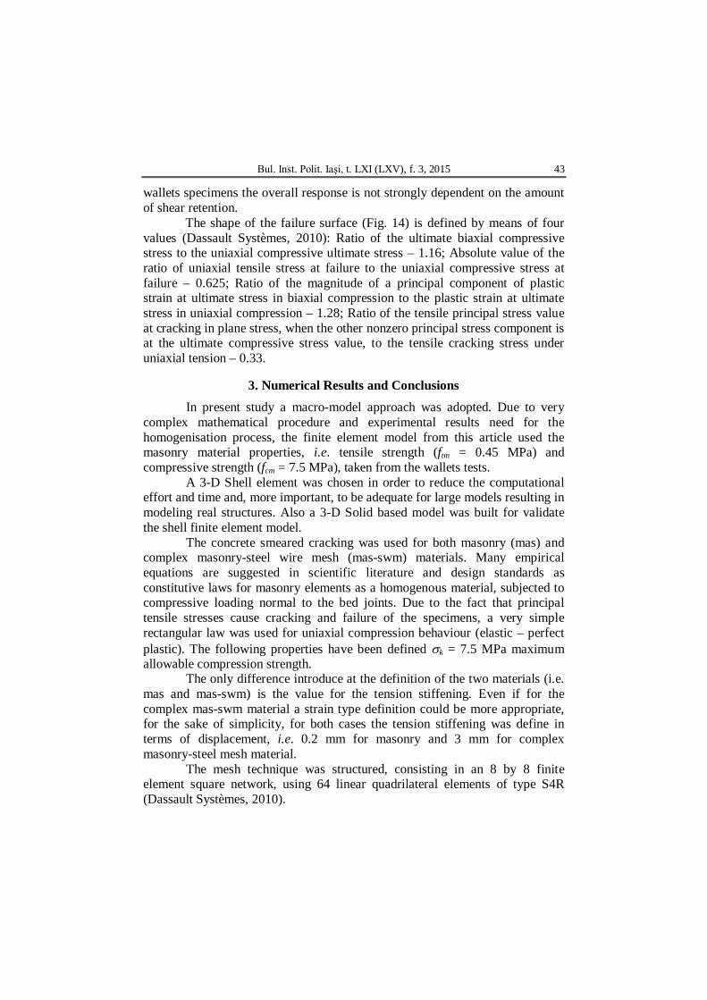
Unfortunately it is most difficult to obtain an almost rigid behaviour until crack and such a “yielding plateaux” behaviour for brittle material laws, therefore a compromise between the numerical and experimental results have to be accepted. Taking into account that this material calibration is intended to be used for global seismic retrofitting analysis of structures, the most important aspects are the energy dissipation, yield-point, ultimate displacement and stiffness. Complex nonlinear behaviour are subject to a linearization process. A bilinear idealization of the behaviour curve it is common practice in performance based evaluation in seismic engineering. In Fig. 15 are shown the numerical results on the retrofitted material. The numerical model stops at 2 mm horizontal displacement. After this point the integrity of the element is compromised.
0
5000
10000
15000
20000
25000
30000
35000
40000
45000
0 0.5 1 1.5 2
App
lied
load
[daN
]
Horizontal opening of the cracks [mm]
Numeric vs. experimental results
Experimental specimen 1
Experimental specimen 2
Experimental specimen 3
Numerical simulationresults
Fig. 15 – Horizontal deformation of masonry (MAS) and (MAS-SWM).
One may notice that the experimental results may be consider as bi-linear simplified behavior of the numerical behavioral curve, keeping unaltered the energy dissipation and yield point.
The numerical simulation have proved that by modifying only one parameter from the material definition (i.e. the displacement in the tension stiffening definition), the numerical model is able to replicate the important increase of strength and deformation capacity. As was before mention, because of the high degree of experimental result scatter (Table 1), is was not the aim of this study to calibrate in detail the material behavior, but only to propose an
Bul. Inst. Polit. Iaşi, t. LXI (LXV), f. 3, 2015 45
equivalent material that easy to be apply in case of an performance based seismic assessment of an existing masonry wall bearing structure. If the energy dissipation, overall capacity and ultimate deformation are almost the same for the elements composed by complex material and the numerical model, then the global assessment is quite fair. It is true that because of the different rigidity of the real element and numerical model, the evaluation of the neighboring elements, such as floors and foundations, should be perform applying other hypothesis.
In conclusion a simple material model assigned to 3-D deformable shell elements could offer a reasonable preliminary estimation of overall benefits of such very complex anti-seismic retrofitting technique. But even so further detailed numerical investigation by means of either 2-D composite shells or 3d solid elements used in a macro or micro-model taking into account the real interaction laws between its components it will be necessary to fully describe the real behavior of the retrofitting solution.
Acknowledgements. This work was partially supported by the strategic grant POSDRU/159/1.5/S/137070 (2014) of the Ministry of National Education, Romania, co-financed by the European Social Fund – Investing in People, within the Sectoral Operational Programme Human Resources Development 2007-2013.
REFERENCES Dogariu A., Seismic Retrofitting Techniques Based on Metallic Materials of RC and/or
Masonry Buildings. Ph. D. Diss., Ed. Politehnica, ISBN 978-973-625-846-7, 2009.
Dhanasekar M, Page A.W., Kleeman P.W., The Failure of Brick Masonry under Biaxial Stresses. Proc. Intsn. Civ. Engrs., Part 2, 79, 295-313 (1985).
Lourenço P.B., Computational Strategies for Masonry Structures. Delft Univ. Press, Stevinweg 1, 2628 CN Delft, The Netherlands, 1996.
Lourenço P.B., Zucchini A., A Homogenization Model for Stretcher Bond Masonry. Computer Methods in Structural Masonry - 5, Eds. T.G. Hughes and G.N. Pande, Computers & Geothecnics, UK, 60-67, 2001.
Lourenço P.B, Experimental and Numerical Issues in the Modelling of the Mechanical Behaviour of Masonry. Structural Analysis of historical constructions II - P. Roca, J.L. González, E. Oñate and P.B. Lourenço (Eds.) CIMNE, Barcelona, 1998.
Page A.W.. The Biaxial Compressive Strength of Brick Masonry. Proc. Intsn. Civ. Engrs., Part 2, 71, pp. 893-906 (1981).
Pande G.N., Liang J.X., Middleton J., Equivalent Elastic Moduli for Brick Masonry. Computers and Geotechnics, 8, 243-265 (1989a).
Pande G.N., Liang J.X.. Middleton J., Equivalent Elastic Moduli for Brick Masonry. Computers and Geotechnics, 8, 243-265 (1989b).
46 Adrian Ioan Dogariu
Rots J.G., Numerical Simulation of Cracking in Structural Masonry. Heron, 36, 2, 49-63 (1991).
Salamon M.D.G., Elastic Moduli of Stratified Rock Mass. Int. J. Rock. Mech. Min. Sci., 5, 519-527 (1968).
Tzamtzis A.D., Finite Element Modeling of Cracks and Joints in Discontinuous Structural Systems. 16th ASCE Engng. Mechan. Conf., July 16-18. 2003, Univ. of Washington, Seattle.
Wang Gang, Li Shaofan, Nguyen Hoang-Nam, Sita Nichloas, Effective Elastic Stiffness for Periodic Masonry Structures via Eigenstrain Homogenization. ASCE J. of Mater. in Civil Engng., 2006.
PROHITECH, Ed. Polimerica, ISBN 978-88-7699-173-8, 2011. * * * Guidelines for Earthquake Resistant Non-Engineered Construction. First printed by
International Association for Earthquake Engineering. IAEE/NICEE, Tokyo, Japan. Reprinted by the National Information Center of Earthquake Engineering, IIT Kanpur, India, 2004.
* * * Earthquake Protection of Historical Buildings by Reversible Mixed Technologies. PROHITECH FP6 INCO-CT-2004-509119/2004
ANALIZA NUMERICĂ A ELEMENTELOR DE ZIDĂRIE CONSOLIDATE CU AJUTORUL ŢESĂTURILOR METALICE
(Rezumat)
Se prezentă programul experimental şi analiza numerică a unei soluţii inovative
de consolidare. Această soluţie se bazează pe lipirea pe suprafaţa pereţilor din zidărie a unei tesături de sârmă din oţel inoxidabil sau zincat (SWM) prin intermediul răşinii epoxidice. Un avantaj important al acestei tehnici îl constituie reversibilitatea acesteia, plasa de sârmă putînd fi îndepărtată prin încălzirea stratului de răşină. Elementele de zidărie consolidate cu plasă de sârmă au un comportament complex şi nu există proceduri analitice pentru proiectarea acestora. Prin urmare, sunt necesare modele numerice avansate calibrate pe baza încercărilor experimentale. Este prezentat în detaliu programul experimental şi modelul cu element finit adoptat pentru elementele de zidărie consolidate. Modelul numeric este calibrat cu ajutorul unor măsurători optice. Programul experimental, parte a unui proiectului european de cercetare PROHITECH, au inclus teste pe sîrme şi ţesături de oţel, pe elemente mici de zidărie consolidate (500 × 500 mm) şi pereţi de zidărie la scară reala (1500 × 1500 mm). Calibrarea numerică a fost făcută cu ajutorul programului de element finit ABAQUS. Înlocuirea zidăriei consolidate cu un material echivalent cu comportament îmbunătăţit, calibrat în urma rezultatelor experimentale, poate simplifica considerabil efortul numeric.