Vol. 5, No. 2/February 1988/J. Opt. Soc. Am. B 467 Numerical analysis of nonlinear coherent couplers exhibiting saturable index changes L. Thylen Ericsson Telecom, S12525 Stockholm, Sweden E. M. Wright and G. I. Stegeman Optical Sciences Center, University of Arizona, Tucson, Arizona 85721 Received July 23, 1987; accepted September 25, 1987 Nonlinear directional coherent couplers are analyzed by using the beam-propagation method. The nonlinear media are modeled by using a saturable two-level system response. Coupler structures and excitation conditions to which the coupled-mode approach is not readily applicable are treated. 1. INTRODUCTION The area of all-optical signal processing has attracted con- siderable interest. Some of the reasons for this are the poten- tial for extreme (picosecond) processing speed, parallelism in computing, and compatibility with optical fibers. One of the elements studied theoretically,'-"1 and to a lesser degree experimentally,' 2 -' 4 is the nonlinear directional coupler for which the transfer characteristics between two waveguides are controlled by the launched optical power. Previous models of the coherent coupler in planar and channel-wave- guide geometries have been based primarily on coupled- mode theory,1- 8 "'1 whereas the more general beam-propaga- tion method (BPM) has been used to confirm qualitatively the predictions of the coupled-mode approach and to ana- lyze situations in which the coupled-mode approach is not readily applicable. 9 1 0 Also, most previous models of the nonlinear coherent coupler (NLCC) have assumed a Kerr- type nonlinearity without loss.14,7,9,10 Because reasonable all-optical switching power levels are highly desirable, mate- rials with large nonlinearities are needed. Such large non- linearities can generally be found only in resonant systems, in which the refractive-index changes are associated with changes in the absorption, both of which saturate at high intensities. It is thus of some interest to analyze NLCC's based on such materials. A coupled-mode analysis of an NLCC incorporating a homogeneous medium with a two- level saturable nonlinearity has been presented, and criteria for switching have been given." The purpose of this paper is to use the BPM to confirm these switching criteria and to further analyze situations where the coupled-mode ap- proach is not readily applicable. These situations include weakly guiding structures, such that the index profiles are appreciably perturbed by the nonlinearity, as well as cases in which the incident beam is misaligned relative to optimal excitation of the waveguide modes. The latter investigation is important for analyzing the stability of the switched state. 2. DEVICE PHYSICS The structure analyzed, shown in Fig. 1, consists of two coupled integrated-optics waveguides with a cosh- 2 -type profile, 1516 the eigenmodes of which are known in closed form. The background refractive index is nb + 6n(lE2), and 3n(lE2) is the field-dependent refractive index whose form will be specified later in this section. Superimposed upon this background index is the cosh- 2 -type profile. The non- linearity in our case is included only through the background index. Both waveguides are identical for low incident pow- ers and are assumed to be terminated at the shortest low- power length l, which corresponds to total transfer from the input to the output channel. The resonant contribution to the susceptibility is modeled as a saturable two-level system.' 7 The real (6x,) and imagi- nary (bxi) parts of the susceptibility are given as Xr 1q 1 + bt2 + q 2 E 2 1 + t 2 + q 2 E2 (1) (2) where the parameters q, and q2 are related to the maximum index change and strength of nonlinearity, respectively, and bt is the normalized detuning. In both cases, as IE -p both 5 X, and 5Xi decay to zero and the background refractive index asymptotically approaches nb. From Eq. (1), the maximum resonant contribution to the susceptibility occurs at bt = ±1. Noting that n 2 = (nb + Mn-ax) 2 = nb 2 + 6 X, ( 6 t +1, IEI - 0), where nb is the low-power background refrac- tive index, the parameter q, can be defined as q = 4 nb 3 nmax' (3) 0740-3224/88/020467-05$2.00 Oc 1988 Optical Society of America Thylen t al.
Transcript
Vol. 5, No. 2/February 1988/J. Opt. Soc. Am. B 467
Numerical analysis of nonlinear coherent couplersexhibiting saturable index changes
L. Thylen
Ericsson Telecom, S12525 Stockholm, Sweden
E. M. Wright and G. I. Stegeman
Optical Sciences Center, University of Arizona, Tucson, Arizona 85721
Received July 23, 1987; accepted September 25, 1987
Nonlinear directional coherent couplers are analyzed by using the beam-propagation method. The nonlinearmedia are modeled by using a saturable two-level system response. Coupler structures and excitation conditions towhich the coupled-mode approach is not readily applicable are treated.
1. INTRODUCTION
The area of all-optical signal processing has attracted con-siderable interest. Some of the reasons for this are the poten-tial for extreme (picosecond) processing speed, parallelismin computing, and compatibility with optical fibers. One ofthe elements studied theoretically,'-"1 and to a lesser degreeexperimentally,' 2 -'4 is the nonlinear directional coupler forwhich the transfer characteristics between two waveguidesare controlled by the launched optical power. Previousmodels of the coherent coupler in planar and channel-wave-guide geometries have been based primarily on coupled-mode theory,1- 8 "'1 whereas the more general beam-propaga-tion method (BPM) has been used to confirm qualitativelythe predictions of the coupled-mode approach and to ana-lyze situations in which the coupled-mode approach is notreadily applicable.9 10 Also, most previous models of thenonlinear coherent coupler (NLCC) have assumed a Kerr-type nonlinearity without loss.14,7,9,10 Because reasonableall-optical switching power levels are highly desirable, mate-rials with large nonlinearities are needed. Such large non-linearities can generally be found only in resonant systems,in which the refractive-index changes are associated withchanges in the absorption, both of which saturate at highintensities. It is thus of some interest to analyze NLCC'sbased on such materials. A coupled-mode analysis of anNLCC incorporating a homogeneous medium with a two-level saturable nonlinearity has been presented, and criteriafor switching have been given." The purpose of this paperis to use the BPM to confirm these switching criteria and tofurther analyze situations where the coupled-mode ap-proach is not readily applicable. These situations includeweakly guiding structures, such that the index profiles areappreciably perturbed by the nonlinearity, as well as cases inwhich the incident beam is misaligned relative to optimalexcitation of the waveguide modes. The latter investigationis important for analyzing the stability of the switched state.
2. DEVICE PHYSICS
The structure analyzed, shown in Fig. 1, consists of twocoupled integrated-optics waveguides with a cosh- 2-typeprofile,1516 the eigenmodes of which are known in closedform. The background refractive index is nb + 6n(lE2), and3n(lE2) is the field-dependent refractive index whose formwill be specified later in this section. Superimposed uponthis background index is the cosh- 2-type profile. The non-linearity in our case is included only through the backgroundindex. Both waveguides are identical for low incident pow-ers and are assumed to be terminated at the shortest low-power length l, which corresponds to total transfer from theinput to the output channel.
The resonant contribution to the susceptibility is modeledas a saturable two-level system.' 7 The real (6x,) and imagi-nary (bxi) parts of the susceptibility are given as
Xr 1q 1 + bt2 + q2E2
1 + t 2 + q2 E2
(1)
(2)
where the parameters q, and q2 are related to the maximumindex change and strength of nonlinearity, respectively, andbt is the normalized detuning. In both cases, as IE -p
both 5X, and 5Xi decay to zero and the background refractiveindex asymptotically approaches nb. From Eq. (1), themaximum resonant contribution to the susceptibility occursat bt = ±1. Noting that n2
= (nb + Mn-ax)2 = nb2 + 6X, (
6t
+1, IEI - 0), where nb is the low-power background refrac-tive index, the parameter q, can be defined as
q = 4
nb3
nmax' (3)
0740-3224/88/020467-05$2.00 Oc 1988 Optical Society of America
Thylen t al.
468 J. Opt. Soc. Ail. B/Vol. 5, No. 2/Fehruary 1988
2k= D
Gt ln(10O0lD) sa
2 x
(b)
An, tn h
I ,
D DFig. 1. Nonlinear directional coupler with cosh-2 waveguide pro-files superimposed upon a background homogeneous medium: (a)layout, (b) index profile.
For at = +1, 6nmax > 0, and for t = -1, 6nmax < 0. For other
values of the detuning, the maximum (saturation) indexchange, IJNsatl, is less than 16nmaxJ, that is,
Nsat =1 +12 nmax (4)
Since q2 essentially normalizes the field to the saturationfield, we set it to unity for convenience. Assuming that t >0, when the optical field is increased, Xr -E2 , which isusually called a self-defocusing nonlinearity. Conversely, aself-focusing nonlinearity is obtained for t < 0.
Before discussing the detailed calculations, it is useful togain some insight into the general implications of the two-level model to switching in a coherent directional coupler.The all-optical switching criterion for a NLCC one couplinglength () long has been found to bell
lckoIANsat > 4, (5)
where ANsat is the saturated effective index change of theguided mode at the specified detuning. Because the wave-guide effective index is essentially the position-dependentrefractive index averaged over the guided-wave-field distri-bution, the power-dependent changes in the material prop-erties also vary over the guided-wave-field distribution.Hence it is necessary to separate changes in the mediumrefractive index (and loss), defined as n(6a), from changesin the waveguide effective index (attenuation), defined asAN(Aat). (See Ref. 18 for a more complete discussion.) Ingeneral Ienmaxj > IANmaxl and, for the case considered here,I6nmax = IANmaxl. Equation (4) is also valid for waveguideeffective indices.
There is also a power-dependent change in the materialand waveguide absorption, as defined by Eq. (2). Further-more, assuming that the only loss arises from the resonantcontribution to the susceptibility, we obtain
ACsatlc = n(1OD/1), (6)
where Act 55t is the maximum waveguide absorption changeassociated with the maximum change in effective indexANsat and D is the corresponding low-power attenuation indecibels. Using the relation between A and AN for a two-level system, one obtains a relation among the device length,the detuning, the loss, and Nsat of the form
This last relation allows one to calculate the required cou-pler length for a specified low power loss and ANsat(bt). Inthe two-level model the absorption decreases more rapidlywith detuning than does the index change, eventually lead-ing to some device length that permits switching for a pre-scribed attenuation. By combining expressions (5) and (7),we obtain the expression
(8)at n( ID)
which gives the minimum detuning required for completeswitching to take place with a loss of D (in decibels). Forexample, specifying D as 3 (10) dB implies that at > 36 (10.9).Performance of real devices will be critically dependent onthe magnitude of the achievable index change and the way inwhich the real and imaginary parts of the nonlinear suscepti-bility vary with wavelength.
3. NUMERICAL RESULTS
The directional coupler is assumed to be excited in one port(waveguide) by the field distribution associated with thelow-power eigenmode of the corresponding guide. In ourBPM treatment the guided-wave-field distributions can anddo change with power. For consistency with the excitationconditions, we evaluate the power in the individual outputchannels by projecting the output fields onto the linear ei-genmodes of the respective waveguides. This correlation isimplemented in order to model an actual application of thedevice, where, in addition to the peak guide intensity or totalpower (defined in some way), the actual field shape is alsoimportant. Using the methods of Ref. 11, we study theproperties of a directional coupler terminated at one cou-pling length, as defined in the linear case. That is, thelaunched power (for the linear case) transfers over (ideally)completely from the launch to the parallel waveguide at theend of the coupler, defined as the cross state. Increasing theoptical launch power causes the two waveguides to becomephase mismatched because of power-dependent refractive-index changes, which inhibit total power crossover. In theideal case there is a characteristic input power for which allthe output power appears in the launch waveguide, whichcorresponds to the bar state.
Two useful figures of merit for a directional coupler arethe cross talk and the insertion loss. These quantities aredefined here as follows: If Pin is the power in the launchwaveguide and P and P2 are the (correlated) output powersin the launch and cross waveguides, respectively, then thecross talk is defined as
cross talk = 10 log[p +2
and the loss is defined as
(dB), (9)
(10)loss = -10 log LPi;P2 ] (dB).
This means that in the low-power, lossless case, the crosstalk is 0 dB (no all-optical switching has occurred); for full
=
(a)I
Thylen et al.
(7)
Vol. 5, No. 2/February 1988/.J. Opt. Soc. Am. B 469
BC
dB
(a)
---- LOSS- X-TALK
it I
0- I
0 - , /
I, .I ,
4 a/w= 8n, L/A
w =Sn, 0 L/X Ep/8t
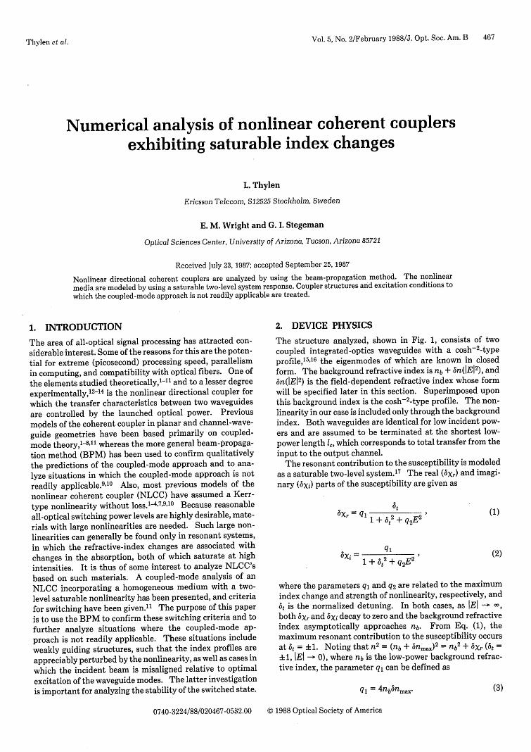
Fig. 2. Cross talk (labeled X-TALK) and attenuation (labeledLOSS) in decibels versus wl, = L = 6250 wavelengths; the 'in.5tvalues used are 0.0005,0.002, and 0.008. The ft values are 5,10, and20 in (a), (b), and (c), respectively. In (d) we plot the cross talk andattenuation versus the quotient of peak normalized electric fieldand normalized detuning (Ep/6t), for w = 2.4, at = 5, and nsat -0.001. The waveguide-profile data are given in the text.
switching from the cross channel to the launch channel, thecross talk is infinity.
The specific numerical parameters used in the calcula-
tions are as follows. The background index was nb = 1.5,
and the maximum index change associated with the cosh- 2 -
type index profile was 0.002-33, with h = 3 pm and a wave-
guide center-to-center separation of 7.64,pm. The low-pow-
er coupling length I, was 3.75 mm (or 6250 vacuum wave-lengths at the 0.6-,4m wavelength, which is assumed
throughout this paper). In all the calculations the trans-
verse window for the BPM was 500 XA/(27r) (or 47.7 Mm),sampled by a 512-point grid. The propagation step is gener-
ally 12 pm.Figures 2-4 show BPM-calculated cross talk and attenua-
tion for the directional coupler depicted in Fig. 1. Theabscissa of Figs. 2(a)-2(c) is the dimensionless parameters
6nsat cW=- X X (11)
where bnsat is the saturated index change for the detuningparameter 6t. From Fig. 2(a) (t = 5), it can be seen that
there is a window 4 > w > 2 in which reasonable switchingperformance is obtained. This fact is not surprising becausean increase in w means an increase in 6n8 at, which, accordingto Eqs. (2) and (3), also increases the absorption, henceimpairing the switching performance for values of w that aretoo large. The higher cross talk can also be seen to becoupled with an increase in loss. In linear directional cou-plers it was previously shown' 6 that combining phase mis-match with absorption precludes achieving perfect switch-ing. For the nonlinear case, increasing at should lead to adecrease in the cross talk as well as in the loss and hence tobetter switching. As shown in Fig. 2(b) for at = 10, w should
be in approximately the same range as for at = 5. However,when at [Fig. 2(c)] reaches 20, the best performance is ob-tained for w > 2.5, with decreased loss as w is increasedfurther up to 5, meaning that larger w values would beallowed in this case. Eventually, when at reaches infinity, aKerr medium results, and good switching performance isobtained for all values of w greater than a certain value. 5 InFigs. 2(a)-2(c), the values of 6nmax are 0.0005, 0.002, and0.008, respectively, and the peak value of the normalized
(o)
dB
O I-200 0
X(C) ---- LOSS
- X-TALK
7500
-200 PROPAGATION DISTANCE (pm)
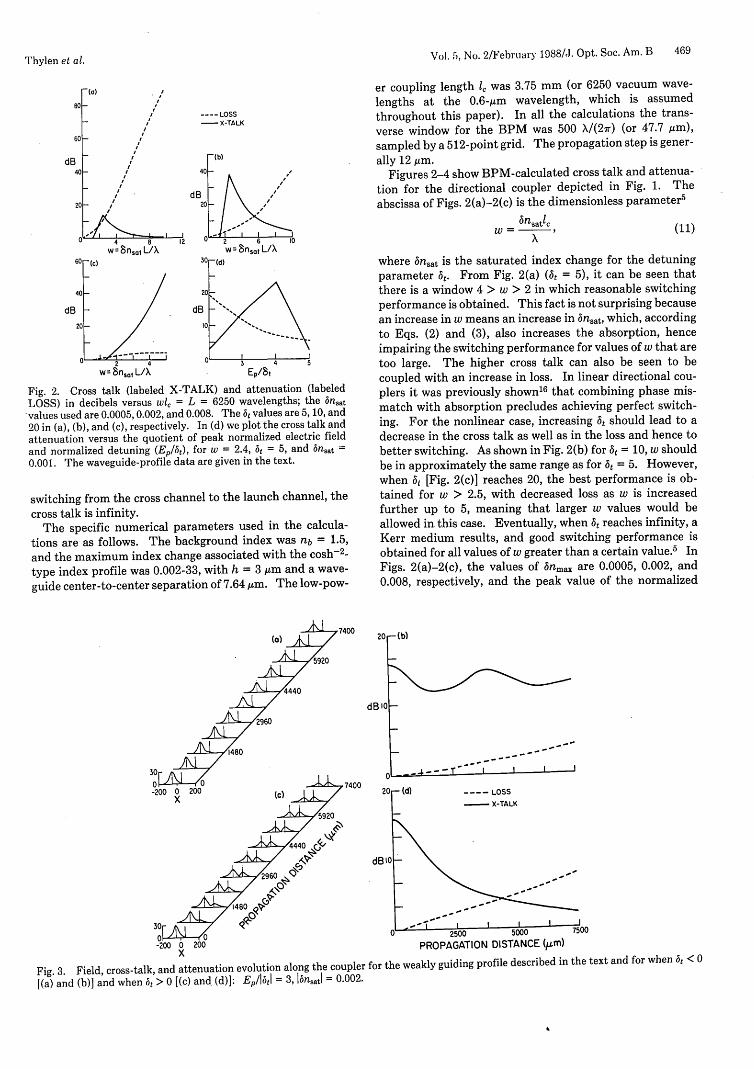
Fig. 3. Field, cross-talk, and attenuation evolution along the coupler for the weakly guiding profile described in the text and for when at <0
[(a) and (b)] and when at > 0 [(c) and (d)]: E,/I1tI = 3, lbnsatl = 0.002.
lThylen et al.
II I
I
II
I
2
,2
11
47() J. Opt. Soc. Am. B/Vol. 5, No. 2/February 1988 'Phylen et al.
(a)
dB 5°~ M
-LOSSX-TALK
25 -
L_------ I I I I2500 5000 7500
PROPAGATION DISTANCE (QLm)Fig. 4. Cross-talk and attenuation evolution along the coupler forthe same profile as treated in Fig. 2, but with an offset of about onethird of the h parameter (or waveguide width): n, 8t = 0.002, E/6t= 3. (a) Outward offset, (b) inward offset.
electric field launched is taken as Ep = 3 6t. (Ep corresponds
to the peak value of the E field at the input of the incidencewaveguide.) Figure 2(d) shows the influence of a varyingelectric field for a fixed detuning of t = 5 and with nsat =0.001. E = 4
t gives better performance than 3 6t, which is
the value used in all of the other figures. However, this isnot expected to change the general results described.
In Fig. 2 we used a profile for which the field-dependentnonlinear index perturbations were small (except for thehighest values of nsat corresponding to t = 5, where thelosses are extremely high), and the predictions of coupled-mode theory generally were confirmed.11 However, in thispaper we also include the case of small detuning and large wvalues, which corresponds to large index perturbations,showing the existence of an optimum range of w values fordetunings of 5-10.
Figure 3 demonstrates the influence of using a weakerguide, such that the power-dependent perturbations of theindex profile significantly affect the guided-wave-field pro-files. The waveguides for this case have a maximum refrac-tive-index step of 0.001 for the cosh- 2 profile, and the widthof the index profile (h parameter referred to above) is 4.56,m, giving the same V value'5 for the waveguide as in Fig. 2.For nma = 0.002 and I1t = 10, w = 2.5 and nsat = 0.0004,which is half of the magnitude of the index step. For thecase of a positive nonlinearity (6t < 0), the index perturba-tion now increases the mode confinement. However, becauseof the index and ensuing field perturbation, the cross-talkvalues increase [relative to the case in Fig. 2(b)] from ap-proximately -40 to -12 dB. For the case of a negativenonlinearity (6t > 0), however, the cross talk increases all theway to -3 dB (and even higher for Ep = 4 t). This increasecan be attributed to the negative index perturbation, whichboth increases the coupling coefficient, and hence affects thepower distribution at the coupler end, and also makes theavailable index changes less efficient for all-optical switch-
ing. This type of behavior can be seen in Fig. 3. The resultsof Fig. 3 could not have been predicted by coupled-modetheory on the basis of the low-power values for the couplingcoefficients.
Another case of interest, in which the coupled-mode ap-proach would be difficult to apply, concerns the properties ofthe coupler when the incident fields do not correspond toeigenmode excitation. The BPM approach is useful forsimulating real experimental situations, in which beam mis-alignments as well as angular and focusing errors occur. Wehave investigated the influence of lateral offsetting, tilting,and adding wave-front curvature to the incident beam at theinput waveguide face. For these investigations 6nmax =0.002, t = 10, and E = 3. The general conclusions arethat wave-front tilts of 10 mrad have only a small influenceon cross talk and loss, whereas increasing the wave-front tiltto 30 mrad increases the cross talk from -40 to -20 dB,irrespective of the sign of the tilt, with an accompanyingincrease in the loss. However, in all cases stable switchingoccurred. The influence of beam curvature was similarlyinvestigated and was found to be roughly independent of thesign of the detuning. We found that wave-front curvatureswith a radius of 700 m can be accommodated with the crosstalk increasing from -40 to approximately -20 dB. Howev-er, an increase in curvature by an additional factor of 2(radius equal to 350,Mm) leads from 0- to -2-dB cross talk,again with stable switching.
Figure 4 shows the influence of an excitation beam offsetof 0.86 ,m, which is approximately one third of the wave-guide width. For an outward offset the cross talk decreasesfrom -40 to -26 dB, and for an inward offset the corre-sponding numbers are -40 to -6 dB, showing a sensitivity tothe sign of the mode displacement, again with stable switch-ing. Figure 4 shows the evolution of cross talk and attenua-tion along the coupler; the abscissa is the propagation dis-tance in units of vacuum wavelength. The low-power cou-pling length is, as before, 6250 wavelengths.
4. DISCUSSION AND SUMMARY
The results presented in Section 3 generally confirm theresults of Ref. 11 for the cases when coupled-mode theory isexpected to apply. However, we found that there is a limit-ed, detuning-dependent range of w parameters that can beused for good cross-talk and attenuation performance; thisfeature was not explicitly shown in Ref. 11. Another differ-ence between the results of Ref. 11 and this paper concernsthe switching versus power characteristics; the xistence of alimited range of Ep/8t for switching to occur shown in Fig.2(d) (t = 5) is not reproduced in Fig.1 of Ref.11. However,in that figure," t = 100, making the situation more Kerr-like than the situation examined here.
Another interesting and not obvious result of the presentwork is that the w parameter of Ref. 11 was calculated byusing the saturated change in effective index (ANsat), where-as the w parameter above is calculated by using the saturat-ed material index change, n.sat. The w-parameter valuesrequired for switching were the same. By varying the exci-tation conditions (offset, tilt, and curvature), we found thatthe switched state was stable with respect to the range ofchanges analyzed here. This result was expected becausethe index perturbation used is significantly smaller than the
'Vol. 5, No. 2/February 19881./. Opt. Soc. Am. B 471Thylen et al.
linear refractive-index step associated with the waveguide.The index steps used in this paper are fairly small (1 X 10⁻³-
2 X 10⁻³). These should, however, be thought of as effective
index steps, since a two-dimensional structure is analyzed.' 5
Good switching performance is obtained even for these com-
paratively weakly guiding structures, provided that the non-
linear index change is small compared with the index step
(see Fig. 3).
ACKNOWLEDGMENTS
This research was sponsored by the National Science Foun-
dation (ECS-8501249), the U.S. Army Research Office
(DAAG29-85-K-0173), and the National Security Adminis-
tration. CPU time from the John Von Neumann Computer
Center is gratefully acknowledged.
REFERENCES
1. S. M. Jensen, IEEE J. Quantum Electron. QE-18, 1580 (1982).2. B. Daino, G. Gregori, and S. Wabnitz, J. Appl. Phys. 58, 4512
(1985).3. S. Trillo and S. Wabnitz, Appl. Phys. Lett. 49, 752 (1986).4. R. Hoffe and J. Chrostowski, Opt. Commun. 57, 34 (1986).5. G. I. Stegeman, C. T. Seaton, C. N. Ironside, T. J. Cullen, and
A. C. Walker, Appl. Phys. Lett. 50, 1035 (1987).
6. G. I. Stegeman, C. T. Seaton, A. C. Walker, C. N. Ironside, andT. J. Cullen, Opt. Commun. 61, 277 (1987).
7. M. Cada, R. C. Gauthier, B. E. Paton, and J. Chrostowski, Appl.Phys. Lett. 49,755 (1986).
8. E. Gaglioti, S. Trillo, S. Wabnitz, B. Daino, and G. I. Stegeman,Appl. Phys. Lett. 51, 293 (1987).
9. L. Thylen, E. M. Wright, G. I. Stegeman, C. T. Seaton, and J. V.Moloney, Opt. Lett. 11, 739 (19.86).
10. S. Wabnitz, E. M. Wright, C. T. Seaton, and G. I. Stegeman,Appl. Phys. Lett. 49, 838 (1986).
11. S. Trillo, S. Wabnitz, E. Caglioti, and G. I. Stegeman, Opt.Commun. 63, 281 (1987).
12. P. Li Kam Wa, J. H. Marsh, and P. N. Robson, Electron. Lett.21, 26 (1985).
13. D. D. Gusovskii, E. M. Dianov, A. M. Maier, V. B. Neustreuev,E. I. Shklovsii, and I. A. Shcherbakov, Sov. J. Quantum Elec-tron. 15, 1523 (1985).
14. S. R. Friberg, Y. Silberberg, M. K. Oliver, M. J. Andrejco, andM. A. Saifi, in Digest of Conference on Lasers and Electro-Optics (Optical Society of America, Washington, D.C., 1987),postdeadline paper.
15. T. Tamir, ed., Integrated Optics (Springer-Verlag, New York,1975), p. 55.
16. C. J. Seterlind and L. Thylen, IEEE J. Quantum Electron. QE-22, 595 (1986).
17. T. Y. Chang, Opt. Eng. 20, 220 (1981).18. M. Romanogli and G. I. Stegeman, "Saturation of guided wave
index with power in nonlinear planar waveguides," Opt. Com-mun. (to be published).