FRASER, R. A. & WARDLE, L. J. (1976). Ghtechnique 26, No. 4, 613-630. Numerical analysis of rectangular rafts on layered foundations R. A. FRASER* and L. J. WARDLE* The behaviour of perfectly smooth, uniformly loaded rectangular rafts of any rigidity resting on a homo- geneous elastic layer which is underlain by a rough rigid base is analysed. Graphical solutions are presented which enable the determination of vertical displacement at the centre, mid-edges and corner of the raft, and the maximum bending moment in the raft. The solutions have been obtained by the finite element method with the interaction between raft and finite soil layer being incorporated through the use of surface elements. A weighting method is presented which allows an approximate isotropic modulus to be derived for a multi-layered soil permitting the solu- tions to be applied to multi-layered foundations. Variations in raft rigidity and length/breadth ratio and soil layer depth and Poisson’s ratio can markedly effect both displacements and bending moments in raft foundations. On analyse le comportement de radiers rectangulaires parfaitement lisses, charges uniformement, de n’im- Porte quelle rigidite, reposant sur une couche elastique homogene sit&e au-dessus d’une base rugueuse, rigide. Des solutions graphiques sont present&es qui permettent la determination du deplacement vertical au centre, au milieu des bords et aux coins du radier, et du moment de flexion maximum dans le radier. Les solutions ont et& obtenues par la methode des 6lCments finis, l’interaction entre radier et la couche de sol d’epaisseur finie &ant prise en compte en utilisant des elements de surface. Une methode de pesanteur est prbent&e, qui permet d’obtenir un module isotrope approximatif pour un sol a couches multiples per- mettant aux solutions d’&tre appliquees aux fonda- tions sur couches multiples. Les variations de la rigidite des radiers, du rapport longueur/largeur, de la profondeur de la couche du sol et du coefficient de Poisson peuvent affecter dune facon marquee aussi bien les dtplacements que les moments de flexion dans les radiers. The designer of rectangular raft foundations has very little information readily available for the estimation of both total and differential settlements and maximum bending moments in the preliminary design phase. Computer programs, e.g. FOCALS (Wardle and Fraser, 1975) are now available which will consider superstructure/raft/soil interaction, but these require the input of raft thickness from a preliminary design for the final detailed design. A crude estimate of maximum differential settlement across a raft and total settlement of the raft can be made using available solutions for uniformly loaded rectangular areas on finite elastic layers. At one extreme full flexibility can be assumed. In this case Ueshita and Meyerhof (1968) and Milovic and Tournier (1971) have presented information on the displacement at the corner of a uniform rectangular load on an elastic layer of finite thickness overlying a rough rigid base. Thus central and differential settlements can be conservatively estimated. At the other extreme of a rigid raft, Giroud (1972) proposed that the average settlement over a uniformly loaded rectangular area on an elastic layer represented the settlement of a rigid rectangular load, and presented appropriate tables of average settlements. However, this technique gives no information about raft thickness for detailed design of a raft of intermediate flexibility. Discussion on this Paper closes 1 March, 1977. For further details see page 648. * CSIRO, Division of Applied Geomechanics, Melbourne, Australia.
Transcript
FRASER, R. A. & WARDLE, L. J. (1976). Ghtechnique 26, No. 4, 613-630.
Numerical analysis of rectangular rafts on layered foundations
R. A. FRASER* and L. J. WARDLE*
The behaviour of perfectly smooth, uniformly loaded rectangular rafts of any rigidity resting on a homo- geneous elastic layer which is underlain by a rough rigid base is analysed. Graphical solutions are presented which enable the determination of vertical displacement at the centre, mid-edges and corner of the raft, and the maximum bending moment in the raft. The solutions have been obtained by the finite element method with the interaction between raft and finite soil layer being incorporated through the use of surface elements. A weighting method is presented which allows an approximate isotropic modulus to be derived for a multi-layered soil permitting the solu- tions to be applied to multi-layered foundations. Variations in raft rigidity and length/breadth ratio and soil layer depth and Poisson’s ratio can markedly effect both displacements and bending moments in raft foundations.
On analyse le comportement de radiers rectangulaires parfaitement lisses, charges uniformement, de n’im- Porte quelle rigidite, reposant sur une couche elastique homogene sit&e au-dessus d’une base rugueuse, rigide. Des solutions graphiques sont present&es qui permettent la determination du deplacement vertical au centre, au milieu des bords et aux coins du radier, et du moment de flexion maximum dans le radier. Les solutions ont et& obtenues par la methode des 6lCments finis, l’interaction entre radier et la couche de sol d’epaisseur finie &ant prise en compte en utilisant des elements de surface. Une methode de pesanteur est prbent&e, qui permet d’obtenir un module isotrope approximatif pour un sol a couches multiples per- mettant aux solutions d’&tre appliquees aux fonda- tions sur couches multiples. Les variations de la rigidite des radiers, du rapport longueur/largeur, de la profondeur de la couche du sol et du coefficient de Poisson peuvent affecter dune facon marquee aussi bien les dtplacements que les moments de flexion dans les radiers.
The designer of rectangular raft foundations has very little information readily available for the estimation of both total and differential settlements and maximum bending moments in the preliminary design phase. Computer programs, e.g. FOCALS (Wardle and Fraser, 1975) are now available which will consider superstructure/raft/soil interaction, but these require the input of raft thickness from a preliminary design for the final detailed design.
A crude estimate of maximum differential settlement across a raft and total settlement of the raft can be made using available solutions for uniformly loaded rectangular areas on finite elastic layers.
At one extreme full flexibility can be assumed. In this case Ueshita and Meyerhof (1968) and Milovic and Tournier (1971) have presented information on the displacement at the corner of a uniform rectangular load on an elastic layer of finite thickness overlying a rough rigid base. Thus central and differential settlements can be conservatively estimated. At the other extreme of a rigid raft, Giroud (1972) proposed that the average settlement over a uniformly loaded rectangular area on an elastic layer represented the settlement of a rigid rectangular load, and presented appropriate tables of average settlements. However, this technique gives no information about raft thickness for detailed design of a raft of intermediate flexibility.
Discussion on this Paper closes 1 March, 1977. For further details see page 648. * CSIRO, Division of Applied Geomechanics, Melbourne, Australia.
614
NOTATION
:, raft thickness raft breadth
1 raft length (12 b)
: raft stiffness factor soil layer depth
VP Poisson’s ratio of raft vs Poisson’s ratio of soil E, modulus of elasticity of raft E, modulus of elasticity of soil E* =E/(l-v”)
P applied uniform load
Ip settlement settlement influence factor
S settlement correction factor for finite layer thickness
E bending moment per unit width bending moment influence factor
R
%v, v-h. h
f
Exe Y, z
Yxv. x=, vz
u’x. Y, z
TXY, x.2, %I+
all, 33, 13
a
R. A. FRASER AND L. J. WARDLE
bending moment correction fac- tor for finite layer thickness
number of plate finite elements cross-anisotropic elastic moduli
(eqns 9) cross-anisotropic Poisson’s ratios
(eqns 9) cross-anisotropic shear modulus (eqns 9)
direct strain components shear strain components direct stress components shear stress components cross-anisotropic elastic con-
For rigid raft foundations on a semi-infinite elastic soil layer there are solutions available for contact stress, bending moment and shear force. Gorbunov-Possadov and Serebrjanyi (1961) have presented solutions for contact pressure and bending moment for a square slab subject to a central concentrated load. Butterfield and Banerjee (1971) have given solutions for settlement and contact pressure for rigid rectangular rafts. Brown (1972) obtained solu- tions for contact pressure and bending moment in rigid, square and rectangular rafts subject to various combinations of concentrated loads. Chan and Cheung (1974) have given values of contact pressure for rectangular and circular rigid footings due to concentric and eccentric loading. These solutions enable an estimate to be made of the bending moment in a rigid footing.
In this Paper, numerical solutions are presented for the displacements and maximum bend- ing moments for uniformly loaded raft foundations of arbitrary flexibility on a homogeneous isotropic elastic layer of finite thickness overlying a rough rigid base. The Appendix shows how the results for the isotropic semi-infinite medium can be applied to a cross-anisotropic semi-infinite medium.
Details of how the graphical solutions presented can provide approximate solutions for multi-layered media are also given.
METHOD
The first satisfactory solutions for square rafts of arbitrary flexibility were obtained by Cheung and Zienkiewicz (1965). The stiffness of the soil was derived from the Boussinesq equation and combined with plate bending finite elements to form a stiffness matrix for the whole system. The displacements were solved using the finite element method. Cheung and Nag (1968) used a similar technique to allow for horizontal contact pressures beneath the raft, and for uplift between the plate and soil. Svec and Gladwell (1973) improved the method of Cheung and Zienkiewicz by assuming a continuous contact pressure distribution, described by a third degree polynomial, under each plate finite element. They also developed a IO-node triangular plate bending element specifically for contact problems.
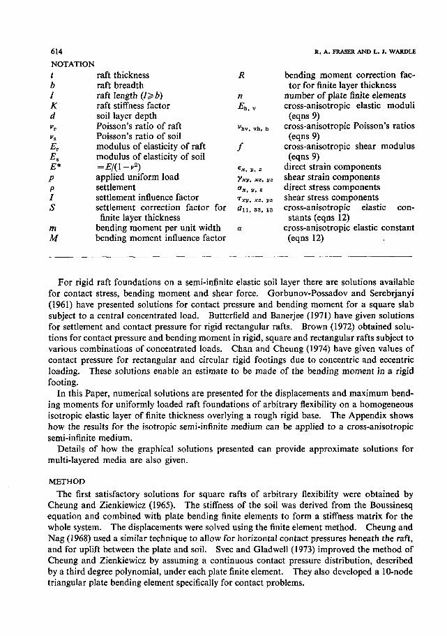
Fig. 1. Convergence of solutions for rigid square raft: (a) settlement; (b) maximum bending moment
Wardle and Fraser (1974) extended the approach of Cheung and Zienkiewicz to ,a multi- layered soil system, investigating the effects of a finite homogeneous soil layer and a soil modulus that increased linearly with depth. The results presented in this Paper have been derived using the computer program FOCALS (Wardle and Fraser, 1975). The computer pro-
gram performs a static elastic analysis of rafts of arbitrary rigidity and variable thickness resting on a layered soil mass. The response of the loaded area of the soil system is modelled using surface elements (Wardle and Fraser, 1975). The surface element stiffness matrix is derived from the surface settlements due to uniformly loaded rectangular areas, obtained using integral transform techniques (Gerrard and Harrison, 1971). The layered soil mass consists of any number of horizontal layers of uniform thickness, with infinite lateral extent. The
bottom layer may rest on a rigid base or extend to infinite depth. The surface element approach offers many advantages over conventional three-dimensional
finite elements. Only the portion of the surface of the soil mass that is loaded needs to be discretized; for conventional finite elements the whole volume of soil needs to be discretized, leading to many degrees of freedom and the imposition of artificial boundary conditions. A comparison between both methods applied to a square raft on a finite layer indicated that the degrees of freedom and band width modelled using surface elements were much smaller than for brick elements and the total solution time was smaller by a factor of 20 (Wardle and Fraser, 1974).
The raft (and any superstructure) is modelled using conventional finite elements. The computer program can also consider rafts that are not rectangular in plan or which contain cut-outs. In addition, cross-anisotropic soil properties can be used. Consideration of anisotropy is particularly important for overconsolidated soils where the deformation moduli in the vertical and horizontal directions are different and the independent shear modulus is lower than expected from isotropic theory (Gerrard et al., 1972).
For simplicity of analysis the contact between the raft and the soil is assumed to be fric- tionless. Hooper (1974) indicated that the presence of an adhesive interface between the raft and the soil can significantly reduce differential raft displacements. For a uniformly loaded
616 R. A. FRASER AND L. J. WARDLE
Fig. 2. raft on homogeneous layer
fully flexible circular raft resting on a semi-infinite soil mass with Poisson’s ratio, Y,, equal to 0, central settlement is reduced by 16% and differential settlement by 44% when full adhesion is considered. For a completely rigid circular raft full adhesion leads to a 9% reduction in settlement for v,=O. When vQ =0*5, no lateral surface displacements occur under the raft
and the adhesive and frictionless cases give identical results. Hooper (1975) demonstrated
similar behaviour for a cross-anisotropic half-space. In practice, interfacial slip will limit
the extent of these reductions.
ACCURACY OF ANALYSIS
The accuracy of the solutions was found to depend markedly on the degree of discretization used. The effect which varying the number of plate elements has on the convergence of the displacements and bending moments is illustrated in Fig. 1, for a rigid square raft on a semi- infinite soil mass. The results for a range of meshes are plotted against .-liz, where n is the
number of plate elements for the whole raft. (Only one quarter of the raft was used in the
computer analysis.) For n > 36, the results fall on a straight line. The correct solution is
assumed to be given by extrapolation of the straight line to the limit r~-l’~ =O. All of the
problems examined in this Paper exhibited similar behaviour. To maximize the accuracy of
the solutions, this extrapolation technique has been used throughout. Confirmation of the likely accuracy of the extrapolated solutions is given by comparison
with other published solutions for the settlement of a uniformly loaded square rigid raft on a
semi-infinite soil mass. The extrapolated solution obtained from Fig. 1 is 1=0.87. By com-
parison, Gorbunov-Possadov and Serebrjanyi (1961) give 1=0.88 and Absi (1970) gives 1=0.87.
INFLUENCE CHARTS
Graphical solutions for the settlements and bending moments in a uniformly loaded rect- angular raft are presented in this section. The supporting soil system consists of a homo-
geneous isotropic layer of thickness d resting on a rigid base (Fig. 2). The stiffness factor for the system is defined by:
. . . . . (1)
where E, is the modulus of elasticity of the raft, vp is the raft Poisson’s ratio, ES is the modulus of elasticity of the soil, Ye is the soil Poisson’s ratio, t is the raft thickness and b is the raft width.
NUMERICAL ANALYSIS OF RECTANGULAR RAFTS ON LAYERED FOUNDATIONS 617
Fig. 3. Settlement influence factor I for d/b=a, (I/b= 1)
The settlements are given by:
where p is the applied uniform pressure and I is the influence factor for the settlement of the raft
p and Z can have the following typical subscripts: A, associated with central settlement (point A, Fig. 2) and AB, associated with differential settlement between centre (point A) and mid-edge (point B) (Fig. 2).
The maximum bending moment per unit width is given by
m =plbM . . . . . . . . . . (3)
where I is the raft length (I> b) and M is the influence factor for the maximum bending moment in a raft. M has the following typical subscript: AB, denoting bending about axis AB.
Because of the concave shape of the displacement profile, caused by the assumption of uniform loading, the maximum bending moments are always positive, i.e. tension at the base
of the raft. In general the maximum bending moment occurs at the centre of the raft, but as the raft stiffness approaches fully flexible, the maximum bending moment moves towards the edge of the raft.
Displacement, differential displacement and bending moment influence factor values for a semi-infinite layer may be read directly from the charts and used in eqns (2) and (3).
For raft foundations with I/b ratios of 1 and 2 correction factors are also provided to correct for the effect of a finite layer depth.
In this case the displacement is given by:
p = SpS’ . . . . . . . . . . (4)
where psi is the displacement for a semi-infinite soil mass and S is a correction factor for the effect of the finite layer depth d. (For a semi-infinite soil mass S equals unity.)
Similarly the maximum bending moment is given by:
m = Rmsi . . . . . . . . . . (5)
where msi is the maximum bending moment for a semi-infinite soil mass and R is a correction factor for the effect of the finite layer depth d.
NUMERICAL ANALYSIS OF RECTANGULAR RAFTS ON LAYERED FOUNDATIONS 619
Fig. 5. Bending moment influence factor M for d/b=oo, (f/b=l)
Charts for I/b = 1
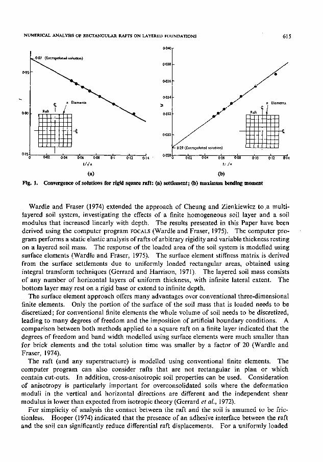
Values of settlement influence factor Z are given in Fig. 3 and correction factors, S, for finite layer depth in Fig. 4. The corresponding bending moment influence factor M and correction factors, R, are given in Figs 5 and 6.
The effects on the finite layer depth are clearly demonstrated by Figs 4 and 6. For a layer thickness equal to the raft width, predictions of total settlement differ by as much as 55x, differential settlement by 18% and maximum bending moment by 15% when compared with a semi-infinite soil mass. In general, the effect of finite layer depth becomes greater as
Poisson’s ratio approaches 0.5. The relative stiffness factor K of the raft-soil system is a major factor in determining its performance. Note that from eqn (l), with other factors kept constant, K is proportional to the ratio of the raft modulus to the soil modulus. Therefore while a raft founded on rock may behave flexibly, the same raft founded on soft clay would behave rigidly.
From Figs 3 and 5 it can be seen that the most rapid change in performance is the range
0.05 < K< 0.5. A system with K less than 0.01 can be considered fully flexible. That is, decreasing the raft
thickness below the value associated with K equal to 0.01 produces only a very small difference in the overall performance of the system. Similarly, a system with K greater than unity can be considered fully rigid, and increasing raft thickness will have little effect on performance.
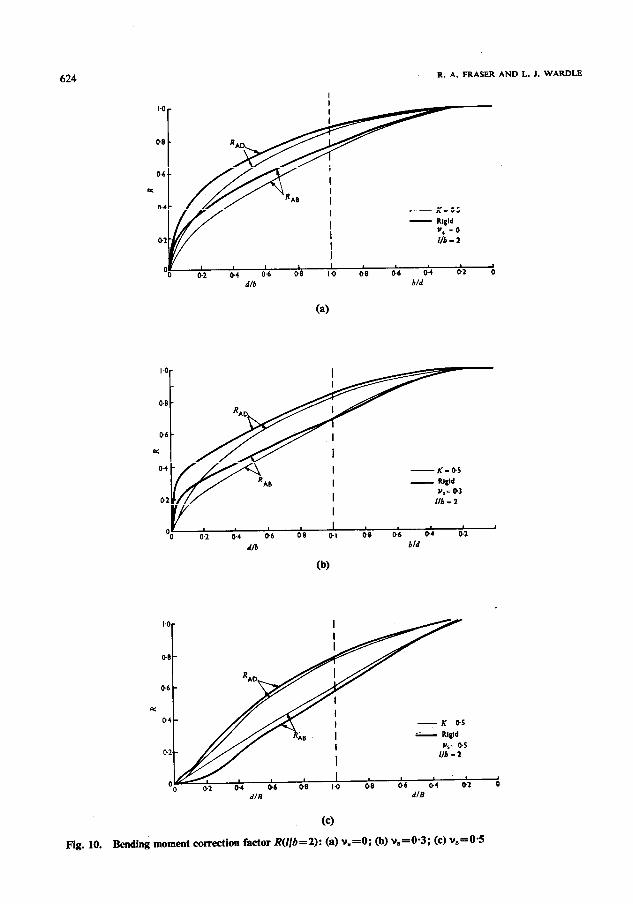
Charts for I/b = 2
The influence charts for I/b = 2 (Figs 7-10) are similar to those for I/b = 1 (Figs 3-6). Again the most rapid change in performance is in the range 0.05 <Kc 0.5, and the effect of finite layer depth becomes greatest as Poisson’s ratio approaches 0.5.
The effect of finite layer thickness is greater than for the case l/b = 1. Considering the effect of a finite layer of thickness b beneath such a raft, it is found that central settlement can be decreased by 63x, differential displacement by 50% and bending moment by 20% in the short direction and by 45% in the long direction from the values for a semi-infinite soil mass.
Charts for 3 c I/b -c 5
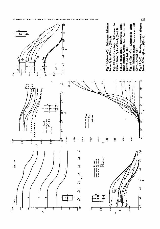
In situations where the l/b value exceeds 2 and consequently falls outside the range of the influence charts in Figs 3 to 10, the charts in Figs 11-16 can be used to provide an estimate of settlement, differential settlement and bending moment.
NUMERICAL ANALYSIS OF RECTANGULAR RAFTS ON LAYERED FOUNDATIONS 621
Fig. 7. Settlement influence factor I for d/h=z , (//h=2)
Figure 11 gives influence coefficients for central displacement for I/b values in the range 1 to 5 for a semi-infinite medium (d/b = a) and Fig. 12 gives similar curves for d/b = 1. Although the actual curves for 3 <I/b < 5 do not actually coincide, the line drawn is accurate to within
+ 5%. Figs 13 and 14 give similar influence coefficients for differential displacement. Fig. 14 provides values of ZAB, ZAG, ZAD directly for 3 <I/b < 5. The curves for these values of l/b do not coincide exactly but are accurate within + 5%. Figs 15 and 16 provide values of maximum bending moment M for d/b equal to infinity and 1 respectively. In Fig. 16 values for v,=O-3 only are given. For K values ranging from flexible to K= 1 they are accurate for all positive values of Poisson’s ratio to within f 10% and for 1 <<KG 10 to within + 30%. For v,=O the value indicated increases, and for vS = 0.5 it decreases.
For values of d/b not equal to 1 or co, the influence coefficients can be obtained by interpola- tion. Charts similar to those in Figs 4,6,8 and 10 should be constructed by drawing a smooth
curve of similar shape through the influence coefficient points for d/b = 0, 1 and co.
NUMERICAL EXAMPLE
Consider a square raft foundation of dimensions 10 m by 10 m and O-5 m thick, subject to a uniform load of 0.1 MPa resting on a soil layer of thickness d=40 m. The raft Young’s modulus, E,, is 15 000 MPa and Poisson’s ratio vr=O*2, and for the soil the values are ES= 83.2 MPa and vS =0=3. Using E,= 15 000 MPa, v,=O*2, t=0*5 m, b=lO-0 m, E,=81*9 MPa, vS =0*3, eqn (1) gives K=O-0289.
Central settlement
For a semi-infinite soil mass, Fig. 3 gives IAs’= 1.10. Eqn (2) then gives:
NUMERICAL ANALYSIS OF RECTANGULAR RAFTS ON LAYERED FOUNDATIONS 623
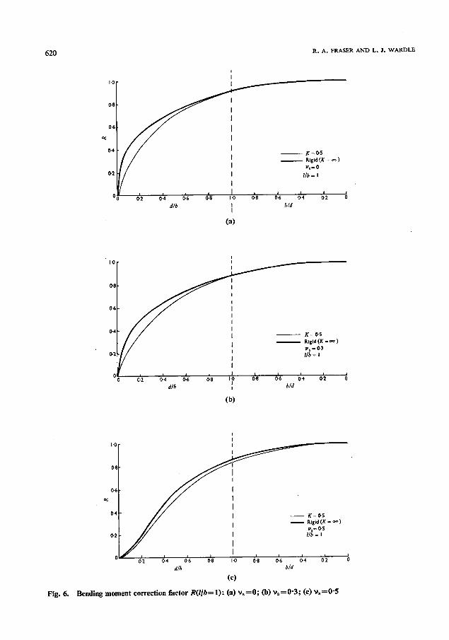
Fig. 9. influence factor M for d/b==, (//h=2)
= 0.1 x 10.0 x 0.91 x l-10 81.9
= 0.0122 m
The correction factor S for the effect of the finite layer depth is obtained from Fig. 4(b). Since K= O-0289 represents a very flexible raft, S, = 0.88 for d/b =4-O. Eqn (4) then gives :
PA = &PASi
= 0.88 x 0.0122 = O-0107 m
Diferential settlement
From Fig. 3, Z,,=O*26, giving p ABsl =O-0029. Multiplying by the correction factor, SA, = l-00 gives :
pAB = @~29 m
Maximum bending moment
For a semi-infinite soil mass, Fig. 5 gives Ms’ =0X105, and from eqn (3)
rnol = O-1 x 10.0 x IO.0 x O-005 = 0.05 MN m/m
From Fig. 6(b), the correction factor R for the effect of the finite layer thickness is l-00. Eqn. (5) then gives
m = l+WxO~O5 = 0.05 MN m/m
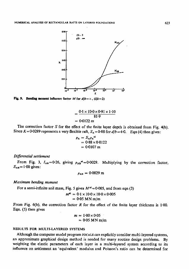
RESULTS FOR MULTI-LAYERED SYSTEMS
Although the computer model program FOCALS can explicitly consider multi-layered systems, an approximate graphical design method is needed for many routine design problems. By weighting the elastic parameters of each layer in a multi-layered system according to its influence on settlement an ‘equivalent’ modulus and Poisson’s ratio can be determined for
NUMERICAL ANALYSIS OF RECTANGULAR RAFTS ON LAYERED FOUNDATIONS 625
a.7
/I
c
4
626
----M AB
- MAD d/b= I
y. = 0.3
R. A. FRASER AND L. J. WARDLE
01 I
104 lo.3 104 10-l I00 IO' IO2 K
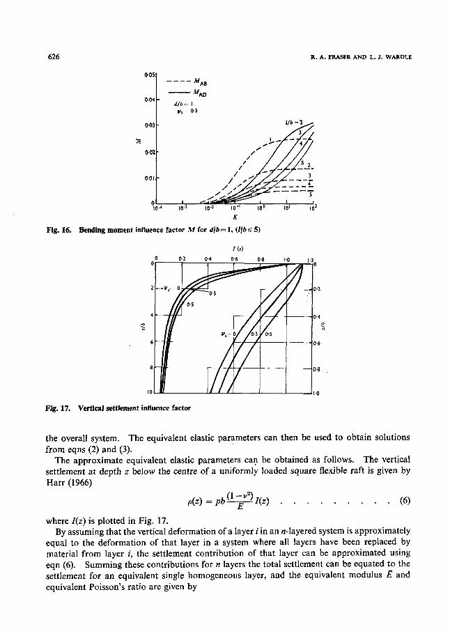
Fig. 16. Bending moment influence factor M for d/b = 1, (I/h < 5)
I Cd
Fig. 17. Vertical settlement influence factor
the overall system. The equivalent elastic parameters can then be used to obtain solutions from eqns (2) and (3).
The approximate equivalent elastic parameters can be obtained as follows. The vertical settlement at depth z below the centre of a uniformly loaded square flexible raft is given by Harr (1966)
p(z) = p6qZ(z) . . . . . . . . . (6)
where Z(z) is plotted in Fig. 17. By assuming that the vertical deformation of a layer i in an n-layered system is approximately
equal to the deformation of that layer in a system where all layers have been replaced by material from layer i, the settlement contribution of that layer can be approximated using eqn (6). Summing these contributions for n layers the total settlement can be equated to the settlement for an equivalent single homogeneous layer, and the equivalent modulus Z? and equivalent Poisson’s ratio are given by
NUMERICAL ANALYSIS OF RECTANGULAR RAFTS ON LAYERED FOUNDATIONS 627
@Oklo 02 I o-4 z/b
0.6 0.8 I 0 2 3 45 10 1 m
1 0.016 -
0014 -
0.012 -
0.010 * 4 2
0008 -
0.006 -
om4 -
om2 -
0 ’ I I I 5 I
1.1 I.0 0.9 0.8 0.7 0.6 05 0.4 0.3 0.2 0-I I(z)
Fig. 18. Variation of l/E* with depth t/b
and
1 B* = j, & AZ’/AZtita’
B = 2 viAZ’/AZsta’ i=l
where E* = E/(1 -2).
. * . . . . . (74
. . . . . . . (7’4
E*i, vi are the elastic parameters for layer number i in the n-layered system, and AZ1=
Z(zL,) - Z(zL,,) where zL zkttom are the depths below the surface of the top and bottom of
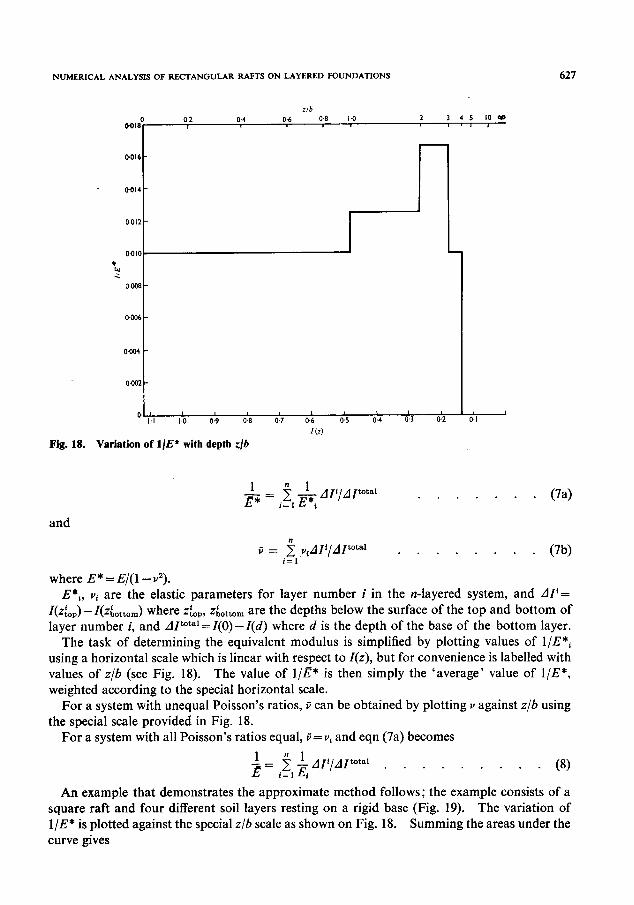
layer number i, and AZ total=Z(0)-Z(d) where d is the depth of the base of the bottom layer. The task of determining the equivalent modulus is simplified by plotting values of l/E*l
using a horizontal scale which is linear with respect to Z(z), but for convenience is labelled with values of z/b (see Fig. 18). The value of l/Z?* is then simply the ‘average’ value of l/E*, weighted according to the special horizontal scale.
For a system with unequal Poisson’s ratios, B can be obtained by plotting v against z/b using the special scale provided in Fig. 18.
For a system with all Poisson’s ratios equal, ij= vi and eqn (7a) becomes
i = $, ; AZ’/AZtotal . . . . . . . . . 1
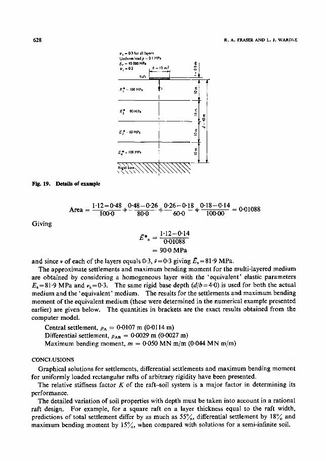
An example that demonstrates the approximate method follows; the exam.ple consists of a square raft and four different soil layers resting on a rigid base (Fig. 19). The variation of l/E* is plotted against the special z/b scale as shown on Fig. 18. Summing the areas under the curve gives
and since v of each of the layers equals 0.3, ij= 0.3 giving $ = 81.9 MPa. The approximate settlements and maximum bending moment for the multi-layered medium
are obtained by considering a homogeneous layer with the ‘equivalent’ elastic parameters I&=81*9 MPa and v,=O*3. The same rigid base depth (d/b=4*0) is used for both the actual medium and the ‘equivalent’ medium. The results for the settlements and maximum bending moment of the equivalent medium (these were determined in the numerical example presented earlier) are given below. The quantities in brackets are the exact results obtained from the computer model.
Central settlement, pA = 0.0107 m (O-01 14 m) Differential settlement, paB = 0.0029 m (0.0027 m) Maximum bending moment, m = 0.050 MN m/m (O-044 MN m/m)
CONCLUSIONS
Graphical solutions for settlements, differential settlements and maximum bending moment for uniformly loaded rectangular rafts of arbitrary rigidity have been presented.
The relative stiffness factor K of the raft-soil system is a major factor in determining its performance.
The detailed variation of soil properties with depth must be taken into account in a rational raft design. For example, for a square raft on a layer thickness equal to the raft width, predictions of total settlement differ by as much as 55x, differential settlement by 18% and maximum bending moment by 15%, when compared with solutions for a semi-infinite soil.
NUMERICAL ANALYSIS OF RECTANGULAR RAFTS ON LAYERED FOUNDATIONS 629
By weighting the elastic parameters of a multi-layered soil system according to their approxi- mate contribution to vertical settlement, an approximate ‘equivalent’ modulus can be obtained. Hence the solutions for a single soil layer can be used for multi-layer systems.
The solutions for uniformly loaded rafts presented should be adequate for preliminary design purposes. However, for a complete analysis, taking into account actual column loads and superstructure rigidity, a computer program such as FOCALS must be used.
ACKNOWLEDGEMENT
Thanks are due to Mr G. Bonner for assistance with the computational work.
APPENDIX: CROSS-ANISOTROPIC SEMI-INFINITE MEDIUM
The results presented for the isotropic semi-infinite medium can also be applied to a cross-anisotropic semi- infinite medium. The stress-strain relationships for a cross-anisotropic material whose axis of elastic sym- metry (z) is vertical can be written
0.x Ez = -“h,--“h,%+~
‘57 h ”
. . . . . . . . . . .
Yxv = (l+v,)Z
TX. Yx. = -
f
YY2 = k
f
The two Poisson’s ratios vhV and yllV are related by
v,,/E, = v,,,/E,, . . . . . . . . . . . . (10)
The vertical settlement p(r) at the surface of a cross-anisotropic semi-infinite medium loaded by a concentrated vertical force P is given by Gerrard and Wardle (1973) as
p(r) = 4a11u33Y2 p - allu33-ua132 nr
. . . . . . . . . . (11)
where r is the distance from the load to the point of interest, and
For an isotropic semi-infinite medium, eqn (11) becomes
p(r)=+-& . . . . . . . . . . . . Comparison of eqns (11) and (13) shows that the vertical load/surface vertical settlement response of a given
cross-anisotropic semi-infinite medium will be the same as that of an isotropic medium for which
ES &1u3P I-v,a= ~11~33-&
. . . . . . . . . . (14)
Using eqn (14), the results for the isotropic semi-infinite medium can be applied to cross-anisotropic semi- infinite media. Note that only the constant E,/(l -v,“) needs to be determined; actual values of E, and yg are not required.
630 R. A. FRASER AND L. J. WARDLE
REFERENCES
Absi, E. (1970). Etude de problbmes particuliers. Annls Inst. Tech. Britim., No. 265, 173-188. Brown, P. T. (1972). Analysis of rafts on clay. PhD thesis, University of Sydney, Australia. Butterfield, R. & Banerjee, P. K. (1971). A rigid disc embedded in an elastic half space. Geotech. Engng 2,
No. 1, 35-52. Chan, H. C. & Cheung, Y. K. (1974). Contact pressure of rigid footings on elastic foundations. Ciu. Engng,
April, 51-59. Cheung, Y. K. & Zienkiewicz, 0. C. (1965). Plates and tanks on elastic foundations-an application of finite
element method. Znt. Jnl Solids Structures 1, No. 4,451461. Cheung, Y. K. &Nag, D. K. (1968). Plates and beams on elastic foundations-linear and non-linear behaviour.
Geotechnique 18, No. 2, 250-260. Gerrard, C. M., Davis, E. H. & Wardle, L. J. (1972). Estimation of the settlements ofcross-anisotropic deposits
using isotropic theory. Aust. Geomech. Jnl G2, No. 1, l-10. Gerrard, C. M. & Harrison, W. J. (1971). The analysis of a loaded half-space comprisedof anisotropic layers.
Technical Paper No. 10. Melbourne: CSIRO Division of Applied Geomechanics. Gerrard, C. M. & Wardle, L. J. (1973). Solutions forpoint loads andgeneralized circular loads applied to a cross-
anisotropic half-space. Technical Paper No. 13. Melbourne: CSIRO Division of Applied Geomechanics. Giroud, J. P. (1972). Settlement of rectangular foundation on soil layer. Jnl Soil Mech. Fdn Dia. Am. Sot.
Civ. Engrs 98, SMI, 149-154. Gorbunov-Possadov, M. I. & Serebrjanyi, R. V. (1961). Design of structures on elastic foundations. Proc.
Fifth Znt. Co& Soil Mech. Fdn Engng, Paris 1,643-648. Harr, M. E. (1966). Foundations of theoretical soil mechanics. New York: McGraw-Hill. Hooper, J. A. (1974). Analysis of a circular raft in adhesive contact with a thick elastic layer. Geotechnique
24, No. 4, 561-580. Hooper, J. A. (1975). Elastic settlement of a circular raft in adhesive contact with a transversely isotropic
medium. Geotechnique 25, No. 4, 691-711. Milovic. D. M. & Tournier, J. P. (1971). Stresses and displacements due to rectangular load on a layer of
finite thickness. Soils Fdns 11, No. 1, l-27. Svec. 0. J. & Gladwell. G. M. L. (1973). A triangular plate bending element for contact problems. Znt. Jnl
Solids Structures 9, 433-446. - _
Ueshita, K. & Meyerhof, G. G. (1968). Surface displacements of an elastic layer under uniformly distributed loads. Highw. Res. Record, No. 288, l-10.
Wardle, L. J. & Fraser, R. A. (1974). Finite element analysis of a plate on a layered cross-anisotropic founda- tion. Proc. First Znt. Conf Finite Element Methods Engng, University of NS W, 565-578.
Wardle, L. J. & Fraser, R. A. (1975). Program FOCAL+foundation on cross anisotropic layered system- user’s manual. Geomechanics Computer Program No. 4. Melbourne: CSIRO Division of Applied Geomechanics.