HAL Id: hal-01184733 https://hal.archives-ouvertes.fr/hal-01184733 Submitted on 17 Aug 2015 HAL is a multi-disciplinary open access archive for the deposit and dissemination of sci- entific research documents, whether they are pub- lished or not. The documents may come from teaching and research institutions in France or abroad, or from public or private research centers. L’archive ouverte pluridisciplinaire HAL, est destinée au dépôt et à la diffusion de documents scientifiques de niveau recherche, publiés ou non, émanant des établissements d’enseignement et de recherche français ou étrangers, des laboratoires publics ou privés. Numerical and experimental characterization of fan noise installation effects. D.C. Mincu, E. Manoha To cite this version: D.C. Mincu, E. Manoha. Numerical and experimental characterization of fan noise installation effects.. AerospaceLab, 2014, p. 1-11. <10.12762/2014.AL07-08>. <hal-01184733>
Transcript
HAL Id: hal-01184733https://hal.archives-ouvertes.fr/hal-01184733
Submitted on 17 Aug 2015
HAL is a multi-disciplinary open accessarchive for the deposit and dissemination of sci-entific research documents, whether they are pub-lished or not. The documents may come fromteaching and research institutions in France orabroad, or from public or private research centers.
L’archive ouverte pluridisciplinaire HAL, estdestinée au dépôt et à la diffusion de documentsscientifiques de niveau recherche, publiés ou non,émanant des établissements d’enseignement et derecherche français ou étrangers, des laboratoirespublics ou privés.
Numerical and experimental characterization of fannoise installation effects.
D.C. Mincu, E. Manoha
To cite this version:D.C. Mincu, E. Manoha. Numerical and experimental characterization of fan noise installation effects..AerospaceLab, 2014, p. 1-11. <10.12762/2014.AL07-08>. <hal-01184733>
Within the context of the two major European Research Projects, NACRE and OPENAIR, the potential of acoustic installation effects on the aft fan noise radiated
by innovative installations of coaxial turbofans are evaluated. Three different installation concepts are considered: a semi-buried engine, a rear-fuselage nacelle and, finally, a scarfed nozzle. The main objective of these concepts is to reduce the acoustic radia-tion of fan noise through the engine nozzle towards the ground, without significant losses in the aerodynamic performance. This evaluation relies on numerical simula-tions achieved with Onera’s solvers, namely sAbrinA-V0 (CAA) and BEMUSE (BEM). The nozzle configurations are typical of coaxial turbofans with a large bypass ratio, including 3D effects from the internal bifurcation and, possibly, the external pylon or fuselage. To obtain a representative fan noise effect, several levels of complexity are used to numerically model the fan noise sources. The most advanced acoustic com-putations rely on Random Phase Multi-modal Injection (RPMI), an innovative technique based on the optimization of the modal phases, in order to obtain, with a minimum number of CAA computations, the contribution of all cut-on modes with evenly dis-tributed acoustic power, summed in an un-correlated way. Noise propagation also accounts for the refraction effects, due to the large velocity gradients in the coaxial flow. For this purpose, non-homogeneous RANS mean flows were computed by Onera, AIRBUS and SNECMA respectively, for the reference (isolated) and the installed confi-gurations, allowing their respective aerodynamic performances to be checked. For all three configurations, the installation effect is evaluated as a combination of the result of the CAA computation in the near-field and an extrapolation in the far-field, using the BEM or Kirchhoff integral methods to take into account the acoustic scattering on dif-ferent fuselage parts. Undeniable benefits in noise reduction by the use of such instal-lations are demonstrated. However, additional studies are still required to confirm these benefits, especially by improving the modeling of the fan noise sources and optimizing the acoustic shielding process.
Introduction
After decades of continuous reduction of the noise radiated by aero-nautic powerplant systems, and especially by modern turbofans with high by-pass ratio, further improvements are now expected from engine installation effects, which means by using the airframe (fuse-lage, wing, empennage), or even the nacelle itself, as noise shielding surfaces through innovative engine integrations.
Current acoustic studies of innovative engine installations rely on combining numerical predictions and experiments, mostly at model
scale. Moreover, the development of innovative numerical methods must rely on a dedicated experimental database, achieved on aca-demic configurations for validation. This was the case, for example, in the European project NACRE (New Aircraft Concepts Research in Europe, 2005-2010) where Airbus recently led studies relating to the RFN concept [1, 2, 3] (Task 3.1 “Rear Fuselage Nacelle”, see figure 1b) combining experiments performed in Onera’s CEPRA19 aeroacoustic open-jet windtunnel and several up-to-date numerical prediction methods for isolated/installed jet and fan noise from a turbofan engine. In the case of the Payload Driven Aircraft (PDA) or “flying wing” configuration [4, 5, 6] (figure 1a), also studied in NACRE
Issue 7 - June 2014 - Numerical and Experimental Characterization of Fan Noise Installation Effects AL07-08 2
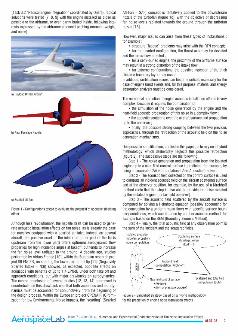
(Task 3.2 “Radical Engine Integration” coordinated by Onera), radical solutions were tested [7, 8, 9] with the engine installed as close as possible to the airframe, or even partly buried inside, following inte-rests expressed by the airframer (reduced pitching moment, weight, and noise).
a) Payload Driven Aircraft
b) Rear Fuselage Nacelle
c) Scarfed aft-fan
Figure 1 - Configurations tested to evaluate the potential of acoustic shielding effect
Although less revolutionary, the nacelle itself can be used to gene-rate acoustic installation effects on fan noise, as is already the case for nacelles equipped with a scarfed air inlet. Indeed, on several aircraft, the positive scarf of the inlet (the upper part of the lip is upstream from the lower part) offers optimum aerodynamic flow properties for high incidence angles at takeoff, but tends to increase the fan noise level radiated to the ground. A decade ago, studies performed by Airbus France [10], within the European research pro-ject SILENCER, on scarfing the lower part of the lip [11] (Negatively Scarfed Intake – NSI) showed, as expected, opposite effects on acoustics with benefits of up to 1.4 EPNdB under both take off and approach conditions, but with major drawbacks on aerodynamics. The central conclusion of several studies [12, 13, 14] addressed to counterbalance this drawback was that both acoustics and aerody-namics must be accounted for conjunctively, from the beginning of the design process. Within the European project OPENAIR (OPtimi-zation for low Environmental Noise impact), the “scarfing” (Scarfed
Aft-Fan – SAF) concept is tentatively applied to the downstream nozzle of the turbofan (figure 1c), with the objective of decreasing fan noise levels radiated towards the ground through the turbofan nozzle [15].
However, major issues can arise from these types of installations ; for example : • structure “fatigue” problems may arise with the RFN concept; • for the scarfed configuration, the thrust axis may be deviated and the mass-flow affected ; • for a semi-buried engine, the proximity of the airframe surface may result in a strong distortion of the intake flow ; • for extreme configurations, the possible ingestion of the thick airframe boundary layer may occur. In addition, certification issues can become critical, especially for the case of engine burst events and, for this purpose, material and energy absorption analysis must be considered.
The numerical prediction of engine acoustic installation effects is very complex, because it requires the combination of: • the simulation of the noise generation by the engine and the near-field acoustic propagation of this noise in a complex flow ; • the acoustic scattering over the aircraft surface and propagation up to the observer ; • finally, the possible strong coupling between the two previous approaches, through the retroaction of the acoustic field on the noise generation mechanisms.
One possible simplification, applied in this paper, is to rely on a hybrid methodology, which deliberately neglects this possible retroaction (figure 2). The successive steps are the following: Step 1 - The noise generation and propagation from the isolated engine up to a near-field control surface is predicted, for example, by using an accurate CAA (Computational AeroAcoustics) solver. Step 2 - The acoustic field collected on the control surface is used to compute an incident acoustic field on the aircraft scattering surface and at the observer position, for example, by the use of a Kirchhoff method (note that this step is also able to provide the noise radiated by the isolated engine to a far-field observer). Step 3 - The acoustic field scattered by the aircraft surface is computed by solving a Helmholtz equation (possibly accounting for the convection by a uniform mean flow) with specific surface boun-dary conditions, which can be done by another acoustic method, for example based on the BEM (Boundary Element Method). Step 4 - Finally, the total acoustic field at any observation point is the sum of the incident and the scattered fields.
Figure 2 - Simplified strategy based on a hybrid methodology for the prediction of engine noise installation effects
Nearfield control surface •Pressure •Normal pressure gradient
Incident fieldcomputation (Kirchhoff)
Engi
ne
Issue 7 - June 2014 - Numerical and Experimental Characterization of Fan Noise Installation Effects AL07-08 3
For several years, Airbus, SNECMA and Onera have collaborated on the development of such hybrid methodology for the prediction of isolated/installed fan noise propagating in the aft direction [16, 17].
This collaboration recently continued within the framework of the NACRE and OPENAIR programs, with the objective of validating this hybrid methodology against available fan noise experimental data-bases. In NACRE, the acoustical measurements were collected during Onera’s above-mentioned CEPRA19 campaign, in which a turbofan nacelle equipped with a TPS (Turbine Powered Simulator) was tested in RFN configuration, with an Airbus model at scale 1/11 (figure 3). The NACRE program ended in early 2010, but the collaboration on this approach between Airbus and Onera continued using their own funding. Regarding the OPENAIR program, an experimental campaign took place in 2012, at QinetiQ, in the NTF open-jet acoustic wind tun-nel. In this campaign, fan noise was simulated with in-duct loudspea-kers rings, instead of the TPS used in NACRE.
NACRE fan noise experiment
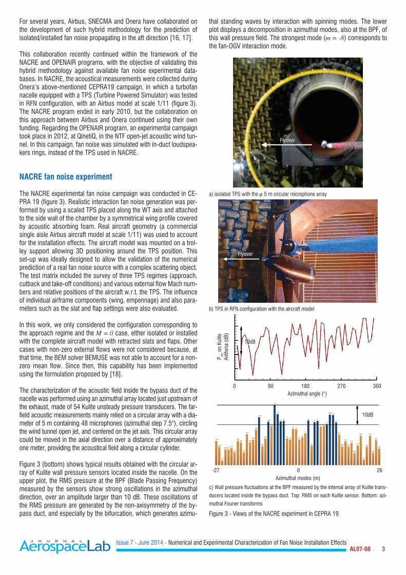
The NACRE experimental fan noise campaign was conducted in CE-PRA 19 (figure 3). Realistic interaction fan noise generation was per-formed by using a scaled TPS placed along the WT axis and attached to the side wall of the chamber by a symmetrical wing profile covered by acoustic absorbing foam. Real aircraft geometry (a commercial single aisle Airbus aircraft model at scale 1/11) was used to account for the installation effects. The aircraft model was mounted on a trol-ley support allowing 3D positioning around the TPS position. This set-up was ideally designed to allow the validation of the numerical prediction of a real fan noise source with a complex scattering object. The test matrix included the survey of three TPS regimes (approach, cutback and take-off conditions) and various external flow Mach num-bers and relative positions of the aircraft w.r.t. the TPS. The influence of individual airframe components (wing, empennage) and also para-meters such as the slat and flap settings were also evaluated.
In this work, we only considered the configuration corresponding to the approach regime and the M = 0 case, either isolated or installed with the complete aircraft model with retracted slats and flaps. Other cases with non-zero external flows were not considered because, at that time, the BEM solver BEMUSE was not able to account for a non-zero mean flow. Since then, this capability has been implemented using the formulation proposed by [18].
The characterization of the acoustic field inside the bypass duct of the nacelle was performed using an azimuthal array located just upstream of the exhaust, made of 54 Kulite unsteady pressure transducers. The far-field acoustic measurements mainly relied on a circular array with a dia-meter of 5 m containing 48 microphones (azimuthal step 7.5°), circling the wind tunnel open jet, and centered on the jet axis. This circular array could be moved in the axial direction over a distance of approximately one meter, providing the acoustical field along a circular cylinder.
Figure 3 (bottom) shows typical results obtained with the circular ar-ray of Kulite wall pressure sensors located inside the nacelle. On the upper plot, the RMS pressure at the BPF (Blade Passing Frequency) measured by the sensors show strong oscillations in the azimuthal direction, over an amplitude larger than 10 dB. These oscillations of the RMS pressure are generated by the non-axisymmetry of the by-pass duct, and especially by the bifurcation, which generates azimu-
thal standing waves by interaction with spinning modes. The lower plot displays a decomposition in azimuthal modes, also at the BPF, of this wall pressure field. The strongest mode (m = -8) corresponds to the fan-OGV interaction mode.
a) isolated TPS with the 5 m circular microphone array
b) TPS in RFN configuration with the aircraft model
c) Wall pressure fluctuations at the BPF measured by the internal array of Kulite trans-
ducers located inside the bypass duct. Top: RMS on each Kulite sensor. Bottom: azi-
muthal Fourier transforms
Figure 3 - Views of the NACRE experiment in CEPRA 19
Azimuthal modes (m)
Azimuthal angle (°)
10dB
10dB
P ms o
n Ku
lite
Anth
ena
(dB)
-27 0 26
0 90 180 270 360
Flyover
Flyover
Issue 7 - June 2014 - Numerical and Experimental Characterization of Fan Noise Installation Effects AL07-08 4
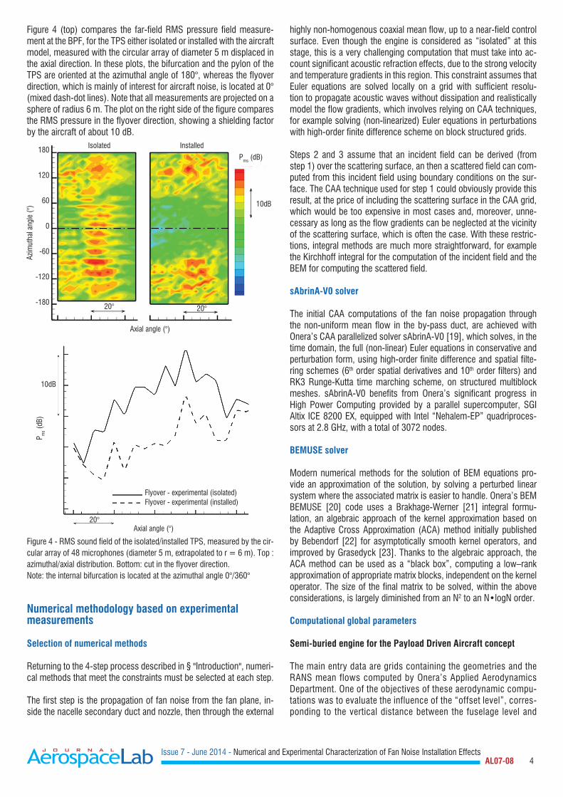
Figure 4 (top) compares the far-field RMS pressure field measure-ment at the BPF, for the TPS either isolated or installed with the aircraft model, measured with the circular array of diameter 5 m displaced in the axial direction. In these plots, the bifurcation and the pylon of the TPS are oriented at the azimuthal angle of 180°, whereas the flyover direction, which is mainly of interest for aircraft noise, is located at 0° (mixed dash-dot lines). Note that all measurements are projected on a sphere of radius 6 m. The plot on the right side of the figure compares the RMS pressure in the flyover direction, showing a shielding factor by the aircraft of about 10 dB.
Figure 4 - RMS sound field of the isolated/installed TPS, measured by the cir-cular array of 48 microphones (diameter 5 m, extrapolated to r = 6 m). Top : azimuthal/axial distribution. Bottom: cut in the flyover direction.Note: the internal bifurcation is located at the azimuthal angle 0°/360°
Numerical methodology based on experimental measurements
Selection of numerical methods
Returning to the 4-step process described in § "Introduction", numeri-cal methods that meet the constraints must be selected at each step.
The first step is the propagation of fan noise from the fan plane, in-side the nacelle secondary duct and nozzle, then through the external
highly non-homogenous coaxial mean flow, up to a near-field control surface. Even though the engine is considered as “isolated” at this stage, this is a very challenging computation that must take into ac-count significant acoustic refraction effects, due to the strong velocity and temperature gradients in this region. This constraint assumes that Euler equations are solved locally on a grid with sufficient resolu-tion to propagate acoustic waves without dissipation and realistically model the flow gradients, which involves relying on CAA techniques, for example solving (non-linearized) Euler equations in perturbations with high-order finite difference scheme on block structured grids.
Steps 2 and 3 assume that an incident field can be derived (from step 1) over the scattering surface, an then a scattered field can com-puted from this incident field using boundary conditions on the sur-face. The CAA technique used for step 1 could obviously provide this result, at the price of including the scattering surface in the CAA grid, which would be too expensive in most cases and, moreover, unne-cessary as long as the flow gradients can be neglected at the vicinity of the scattering surface, which is often the case. With these restric-tions, integral methods are much more straightforward, for example the Kirchhoff integral for the computation of the incident field and the BEM for computing the scattered field.
sAbrinA-V0 solver
The initial CAA computations of the fan noise propagation through the non-uniform mean flow in the by-pass duct, are achieved with Onera’s CAA parallelized solver sAbrinA-V0 [19], which solves, in the time domain, the full (non-linear) Euler equations in conservative and perturbation form, using high-order finite difference and spatial filte-ring schemes (6th order spatial derivatives and 10th order filters) and RK3 Runge-Kutta time marching scheme, on structured multiblock meshes. sAbrinA-V0 benefits from Onera’s significant progress in High Power Computing provided by a parallel supercomputer, SGI Altix ICE 8200 EX, equipped with Intel “Nehalem-EP” quadriproces-sors at 2.8 GHz, with a total of 3072 nodes.
BEMUSE solver
Modern numerical methods for the solution of BEM equations pro-vide an approximation of the solution, by solving a perturbed linear system where the associated matrix is easier to handle. Onera’s BEM BEMUSE [20] code uses a Brakhage-Werner [21] integral formu-lation, an algebraic approach of the kernel approximation based on the Adaptive Cross Approximation (ACA) method initially published by Bebendorf [22] for asymptotically smooth kernel operators, and improved by Grasedyck [23]. Thanks to the algebraic approach, the ACA method can be used as a “black box”, computing a low–rank approximation of appropriate matrix blocks, independent on the kernel operator. The size of the final matrix to be solved, within the above considerations, is largely diminished from an N2 to an N•logN order.
Computational global parameters
Semi-buried engine for the Payload Driven Aircraft concept
The main entry data are grids containing the geometries and the RANS mean flows computed by Onera’s Applied Aerodynamics Department. One of the objectives of these aerodynamic compu-tations was to evaluate the influence of the “offset level”, corres-ponding to the vertical distance between the fuselage level and
Issue 7 - June 2014 - Numerical and Experimental Characterization of Fan Noise Installation Effects AL07-08 5
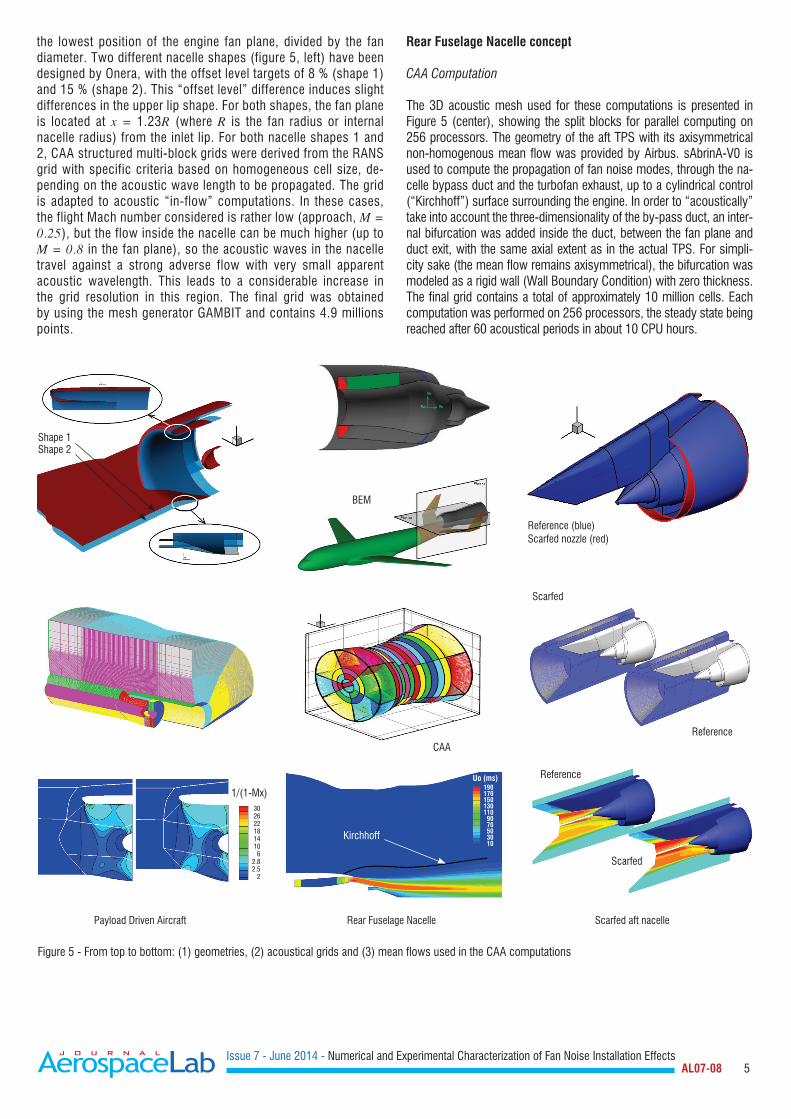
the lowest position of the engine fan plane, divided by the fan diameter. Two different nacelle shapes (figure 5, left) have been designed by Onera, with the offset level targets of 8 % (shape 1) and 15 % (shape 2). This “offset level” difference induces slight differences in the upper lip shape. For both shapes, the fan plane is located at x = 1.23R (where R is the fan radius or internal nacelle radius) from the inlet lip. For both nacelle shapes 1 and 2, CAA structured multi-block grids were derived from the RANS grid with specific criteria based on homogeneous cell size, de-pending on the acoustic wave length to be propagated. The grid is adapted to acoustic “in-flow” computations. In these cases, the flight Mach number considered is rather low (approach, M = 0.25), but the flow inside the nacelle can be much higher (up to M = 0.8 in the fan plane), so the acoustic waves in the nacelle travel against a strong adverse flow with very small apparent acoustic wavelength. This leads to a considerable increase in the grid resolution in this region. The final grid was obtained by using the mesh generator GAMBIT and contains 4.9 millions points.
Rear Fuselage Nacelle concept
CAA Computation
The 3D acoustic mesh used for these computations is presented in Figure 5 (center), showing the split blocks for parallel computing on 256 processors. The geometry of the aft TPS with its axisymmetrical non-homogenous mean flow was provided by Airbus. sAbrinA-V0 is used to compute the propagation of fan noise modes, through the na-celle bypass duct and the turbofan exhaust, up to a cylindrical control (“Kirchhoff”) surface surrounding the engine. In order to “acoustically” take into account the three-dimensionality of the by-pass duct, an inter-nal bifurcation was added inside the duct, between the fan plane and duct exit, with the same axial extent as in the actual TPS. For simpli-city sake (the mean flow remains axisymmetrical), the bifurcation was modeled as a rigid wall (Wall Boundary Condition) with zero thickness. The final grid contains a total of approximately 10 million cells. Each computation was performed on 256 processors, the steady state being reached after 60 acoustical periods in about 10 CPU hours.
Figure 5 - From top to bottom: (1) geometries, (2) acoustical grids and (3) mean flows used in the CAA computations
Shape 1
Scarfed
CAA
Uo (ms)
1/(1-Mx)1901701501301109070503010
302622181410
62.82.5
2
Kirchhoff
Scarfed
Reference
Reference
BEM
Reference (blue)Scarfed nozzle (red)
Shape 2
Issue 7 - June 2014 - Numerical and Experimental Characterization of Fan Noise Installation Effects AL07-08 6
BEM Computation
The final objective is to use Onera’s BEM solver BEMUSE to compute acoustic installation effects from the acoustic fields collected on the Kirchhoff surface. The position of the control surface is critical. It must be close enough to the nozzle so that the grid stretching in the radial direction does not induce significant numerical dissipation, but not too close, in order to avoid mean flow gradients on the surface. This optimal position was generated with GAMBIT and the acoustic field for each computation was simply interpolated using the graphic sol-ver TECPLOT. The radiation surface was discretized, within classical BEM constraints (6 p.p.w.), with an unstructured grid of about 135000 points. The objective of this work is to simulate the acoustic installation effects of the TPS in the presence of the aircraft model. Figure 5 (top, center) shows the configuration that is targeted to investigate this pro-blem. The complete aircraft geometry is drawn in green and the control (“Kirchhoff”) surface, which is used to compute the incident field, is shown in grey (corresponding to the black line in the respective CFD plot). Considering the TPS aft fan noise directivity, with a main lobe directed in the downstream direction, and with a view to considerably lighten the BEM computation, only the rear part of the aircraft (shown in green/red in figure 5, top-center) will be considered in the simulations of installation effects (note that this part contains about 25% of the elements of the entire aircraft, about 118 000 points).
Scarfed aft-fan (SAF)
The acoustical grid of the reference case for the CAA computation was designed by scaling the one described in references [24, 25] and modifying it to propagate all cut-on helicoidal modes in the outer field with at least 16 ppw (points per wavelength). The aerodynamic optimization process of the scarfed nacelle geometry was perfor-med by SNECMA and the final configuration was proposed for the acoustical numerical computation. The scarfing of the nozzle was performed by distorting the reference CAA grid into the prescribed shape, keeping the same grid topology. The final CAA computational mesh is composed of about 24 million cells. The RANS stationary mean flow (Figure 3, right, bottom) for both configurations was also performed by SNECMA (using Onera’s Navier-Stokes code elsA), using the same inflow conditions as for the reference case. As was expected, preserving the mass flow rate through a smaller section involves flow acceleration in the axial direction, as can be observed in figure 5 (right, bottom), where the longitudinal velocity component is
presented in the symmetry plane. One interesting point is that the flow is highly accelerated in the engine axis vicinity and in the downstream part of the pylone, where the acoustical waves generated by the fan are less energetical.
Fan noise sources
In an infinite annular duct with uniform flow, any acoustic field can be decomposed as a sum of rotating mode patterns with circumfe-rential and radial (order m and n) pressure distributions, which are the elementary solutions of the convected Helmholtz equation with rigid wall boundary conditions. For real wave numbers, the modes are “cut-on”, which means that they propagate in the upstream and/or the downstream directions. Fan tonal noise is generated by rota-ting forces on blades and periodic load fluctuations due to the wake interaction between the fan rotor and stator and the interaction of the fan with the ingested part of the stationary non-uniform mean flow. Note that fan noise also includes a broadband noise with two main components; firstly, the interaction noise [26] due to the turbulence ingested by the rotating fan (low frequency) and secondly the trailing edge noise (or self-noise) [27] generated by the turbulent boundary layer developed on the blade (and vane) surface (high frequency). However, this broadband noise is beyond the scope of this work. In sAbrinA-v0, the modes are injected, in terms of the usual boundary condition (BC), by imposing the downstream analytical solution in fictitious cells at each time step and taking into account the phase dependency.
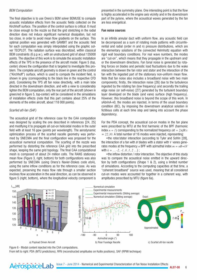
For the PDA concept, the acoustical cut-on modes in the fan plane were prescribed by MTU at the first harmonic of the BPF (harmonic index n = 1) corresponding to the normalized frequency kR = 2fR/c = 22.30. A total number of 16 modes were injected, representing: •the rotor/stator interaction (according to Tyler and Sofrin [28], the interaction of a fan with B blades with a stator with V vanes gene-rates modes at the frequency n BPF with azimuthal index m = nB+kV with k = … -2, -1, 0, 1, 2 …) ; •the inflow distortion / rotor interaction. The objective of this study was to compare the acoustical noise emitted in the upward direc-tion by both configurations (Shape 1 & 2), using a limited number of simulations. According to the computing capacities at that time, a “coherent broadband” source was used, meaning that all considered cut-on modes were accounted for together in a coherent way, with amplitudes prescribed by MTU (figure 6a).
a) Payload Driven Aircraft b) Rear Fuselage Nacelle c) Scarfed aft-fan nacelle
Figure 6 - Modal content injected into the CAA computations. From left to right: PDA (MTU predictions), RFN (reconstructed amplitudes on Kulite positions), SAF (RPMI technique)
Issue 7 - June 2014 - Numerical and Experimental Characterization of Fan Noise Installation Effects AL07-08 7
Lately, within the RFN program, this assumption has been revisited. The acoustic radiation resulted from the un-correlated sum of “cut-on” modes and the Kulite circular array was assumed to provide a good approximation of this modal distribution. From the experimen-tal mode detection shown in figure 2, we only retained 13 azimu-thal modes within a dynamics (or level range) of 10 dB below the maximum (shown in blue in figure 3), each contributing with one or two “cut-on” radial modes (n = 1 and n = 2). Finally, 23 different computations were performed for individual modes with an arbitrary amplitude of unity. Then, for each mode, a Kirchhoff integral method was used to derive the far-field noise from the control (“Kirchhoff”) double layer surface, with a section as indicated with a black line in figure 5.
The experimental in-duct detection does not provide any information on the relative power of two different radial modes having the same azimuthal order, as was the case with the MTU prescriptions. For this reason, in the final summation, the amplitudes of the (m, 1) and (m, 2) modes were arbitrarily adjusted to have the same acoustic power. In the process of summing the contributions of all 23 modes, each injected mode distributes its own energy to many other azimu-thal (and probably radial) modes, due to the presence of the bifur-cation. In order to solve this amplitude problem, the assumption of acoustic linearity was considered. The modal detection process was applied to the acoustic field radiated by all 23 individual modes and these results contributed to building a matrix problem that is used to find the source modal distribution (again, assuming that radial modes n = 1 and n = 2 have identical power) generating the experimental modal detection. These amplitudes were finally used to combine all modes and obtain estimations of the acoustic near-field and far-field. The near-field results are presented in figure 6b, in the form of the distribution of the RMS pressure at the positions of the Kulite sensors, compared to corresponding experimental data. The raw data (in thin lines) shows that there is a fair qualitative and quantitative agreement between the simulation and the mea-surement, although the amplitude of the oscillations is larger for the measurements. The same results are shown after applying a sliding average (thick lines), showing a good agreement (maximum difference inferior to 4 dB) between the numerical fitting and the experimental measurements.
The approach used to simulate the source in the RFN configuration was possible because the acoustical modal content was well known and the number and acoustical properties of modes were available. When experimental data on the in-duct modal content does not exist, which is the case in the scarfed nozzle configuration studied in OPENAIR, all cut-on modes must be considered, generally with amplitudes that are scaled with the assumption of evenly distri-buted acoustic power. This approach is often denoted as “broad-band sum”, although the context remains in the “tonal noise”, at frequencies harmonics of the BPF. Using this approach involves an important number of numerical simulations. On the other hand, if all modes are injected simultaneously (coherent sum), strong interac-tions will occur between modes and the final solution may not be representative of the physics.
In this context, the RPMI (Random Phase Multi-modal Injection) method was developed [29, 30] to associate a random phase to each duct mode and to launch a limited number of independent simulations, or “RPMI events”, much smaller than the original num-ber ”n” of modes, preserving the non-interaction effects. Finally, a
hundred azimuthal/radial cut-on modes are injected simultaneously, their amplitude being set to obtain the same acoustic power for each mode. Using this RPMI technique, only 10 different simula-tions were needed to achieve duct convergence.
Results
Payload Driven Aircraft concept
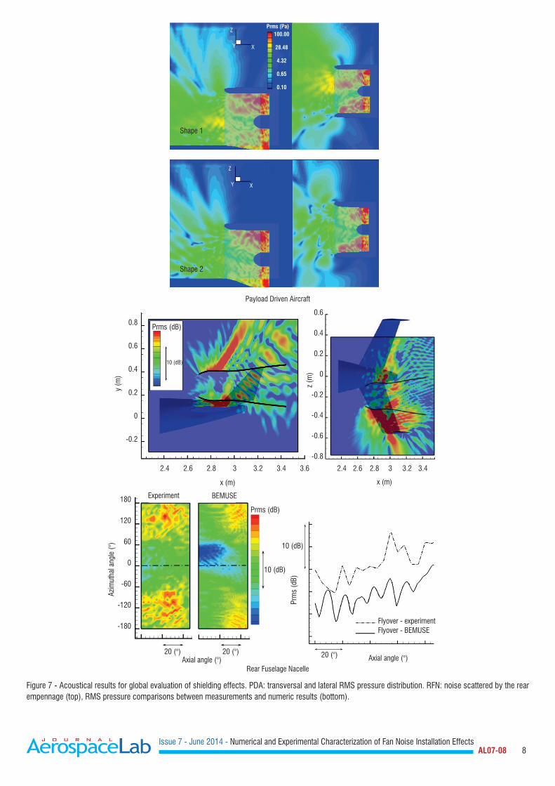
For the “coherent broadband” case (figure 7, top), there is an inte-gration (or averaging) of the effects by all superimposed modes and the level difference between both shapes is less pronounced, although in favor of shape 2. For this case, it is interesting to notice that, whatever the nacelle shape, either n° 1 or n° 2, the radiated noise field is not symmetrical with respect to the nacelle median plane (y = 0). In these figures, we compare iso-contours of the RMS pressure, in horizontal and vertical planes. This very different acoustic behavior for shape 1 and shape 2 is not easily explained. It makes sense that, in the case of shape 2, the steeper slope at the lower part of the nacelle increases the proportion of acoustic energy that is reflected back, in the inward direction. These reflected waves should combine with the incident waves and produce some weak “standing waves” and a close examination of the RMS field inside the nacelles actually shows slight oscillations, which are more pro-nounced for shape 2 than for shape 1. However, those reflected waves are rapidly convected downstream and should fully reflect on the fan plane, where the acoustic mode is injected (a surface that acts as a rigid boundary for the waves coming from within the com-putational domain). One last unknown point is how much acoustic energy can be dissipated through the acoustic propagation in strong mean flow gradients. Rear Fuselage Nacelle concept
In this part, installation effects have been computed with BEMUSE for all individual modes, from their own surface pressure fields indi-vidually computed with sAbrinA-V0 on the control surface. Then, the total (scattered + direct) acoustic field was computed as an uncor-related sum of all mode contributions. The results are presented in Figure 7 (bottom). On the left side (bottom), we compare the experimental result to the numerical result obtained with BEMUSE. From a qualitative point of view, the comparison is satisfying, espe-cially with a shadow zone that is shifted towards the positive azi-muthal angles, due to the relative engine aircraft position. However, a detailed comparison of the levels, either observed or computed, in the flyover direction (right-side plot) shows that the computation underestimates the experimental level by 7-8 dB. Two points are still very encouraging. It can be observed that the same modulation is preserved between the simulation and the experiments, and also the same slope of directivity. Within these considerations, the engine can be now moved in its axial direction to find the optimum posi-tion. In the future, the differences between the prediction and the measurement for this axial position may be reduced by increasing the amount of cut-on modes, which is limited in this simulation, and propagating them over a more realistic internal mean flow (the bifurcation thickness is not taken into account in the CFD). The re-cent implementation of the mean flow in the BEM solver now allows some flow gradients to be taken into account. Finally, a supplemen-tary effect could be added, by also taking into account the inlet fan propagation, as shown in [31].
Issue 7 - June 2014 - Numerical and Experimental Characterization of Fan Noise Installation Effects AL07-08 8
Payload Driven Aircraft
Rear Fuselage Nacelle
Figure 7 - Acoustical results for global evaluation of shielding effects. PDA: transversal and lateral RMS pressure distribution. RFN: noise scattered by the rear empennage (top), RMS pressure comparisons between measurements and numeric results (bottom).
Shape 1
Prms (Pa)
Prms (dB)
Prms (dB)
Experiment BEMUSE
Prm
s (d
B)
y (m
)
z (m
)
x (m) x (m)
Azim
utha
l ang
le (°
)
20 (°)20 (°)20 (°)
10 (dB)
10 (dB)
10 (dB)
Z
Z
Y
Y
X
X
100.00
28.48
4.32
0.65
0.10
Shape 2
0.8
0.6
0.4
0.2
0
-0.2
180
120
60
0
-60
-120
-180
0.6
0.4
0.2
0
-0.2
-0.4
-0.6
-0.8
2.4 2.6 2.8 3 3.2 3.4 3.6 2.4 2.6 2.8 3 3.2 3.4
Axial angle (°) Axial angle (°)
Flyover - experimentFlyover - BEMUSE
Issue 7 - June 2014 - Numerical and Experimental Characterization of Fan Noise Installation Effects AL07-08 9
Scarfed aft-fan concept
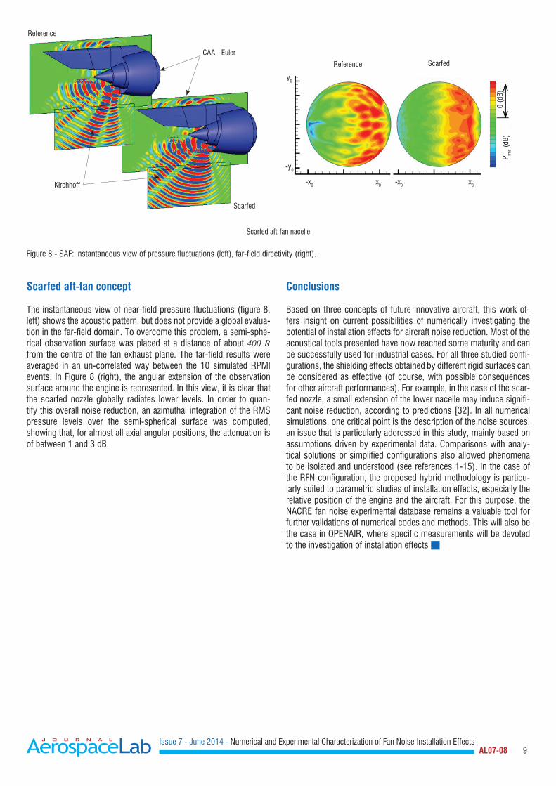
The instantaneous view of near-field pressure fluctuations (figure 8, left) shows the acoustic pattern, but does not provide a global evalua-tion in the far-field domain. To overcome this problem, a semi-sphe-rical observation surface was placed at a distance of about 400 R from the centre of the fan exhaust plane. The far-field results were averaged in an un-correlated way between the 10 simulated RPMI events. In Figure 8 (right), the angular extension of the observation surface around the engine is represented. In this view, it is clear that the scarfed nozzle globally radiates lower levels. In order to quan-tify this overall noise reduction, an azimuthal integration of the RMS pressure levels over the semi-spherical surface was computed, showing that, for almost all axial angular positions, the attenuation is of between 1 and 3 dB.
Conclusions
Based on three concepts of future innovative aircraft, this work of-fers insight on current possibilities of numerically investigating the potential of installation effects for aircraft noise reduction. Most of the acoustical tools presented have now reached some maturity and can be successfully used for industrial cases. For all three studied confi-gurations, the shielding effects obtained by different rigid surfaces can be considered as effective (of course, with possible consequences for other aircraft performances). For example, in the case of the scar-fed nozzle, a small extension of the lower nacelle may induce signifi-cant noise reduction, according to predictions [32]. In all numerical simulations, one critical point is the description of the noise sources, an issue that is particularly addressed in this study, mainly based on assumptions driven by experimental data. Comparisons with analy-tical solutions or simplified configurations also allowed phenomena to be isolated and understood (see references 1-15). In the case of the RFN configuration, the proposed hybrid methodology is particu-larly suited to parametric studies of installation effects, especially the relative position of the engine and the aircraft. For this purpose, the NACRE fan noise experimental database remains a valuable tool for further validations of numerical codes and methods. This will also be the case in OPENAIR, where specific measurements will be devoted to the investigation of installation effects
Issue 7 - June 2014 - Numerical and Experimental Characterization of Fan Noise Installation Effects AL07-08 10
Acknowledgements
The authors deeply acknowledge the helpful contributions from their colleagues at Onera, Cyril Polacsek, Thomas le Garrec and Gabriel Reboul (Aeroa-coustics Team) and Xavier Juvigny (High Performance Computing Team), for fruitful discussions about the modal description of sound fields in nacelles and the computational process.
The research presented in this paper has received funding from the European Commission under OPENAIR Grant Agreement No. 234313 (FP7) and NACRE Grant Agreement No. 516068 (FP6). The authors are grateful to Onera's focal points Franck Cléro for the OPENAIR project, Alain Julienne for NACRE Task 3.1 on the Rear Fuselage Nacelle and Jean-Luc Godard for NACRE Task 3.2 on Payload Driven Aircraft).
References
[1] D.C. MINCU, E. MANOHA, C. PARZANI, J. CHAPPUIS, S. REDONNET, R. DAVY, M. ESCOUFLAIRE - Numerical and Experimental Characterization of Aft - Fan Noise for Isolated and Installed Configurations. AIAA-2010-3918, 16th AIAA/CEAS Aeroacoustics Conference, Stockholm, Sweden, June 2010.[2] S. BARRÉ, S. LEMAIRE, L. DAUMAS, V. LEVASSEUR - Prédiction des effets de l'installation motrice sur le bruit généré par un avion d'affaire. 43rd 3AF Applied Aerodynamics Conference, 10, 11 and 12 March 2008, Poitiers (France).[3] J. DIERKE, R. EWERT, J. CHAPPUIS, S. LIDOINE, J. RICOUARD - The Influence of Realistic 3-D Viscous Mean Flow on Shielding of Engine-Fan Noise by a 3-Element High-Lift Wing. AIAA-2010-3917, 16th AIAA/CEAS Aeroacoustics Conference, Stockholm, Sweden, June 2010.[4] E. MANOHA, D.C. MINCU - Numerical Simulation of the Fan Noise Radiated Through a Semi-Buried Air Inlet. AIAA Paper No. AIAA-2009-3293, AIAA/CEAS Aeroacoustics Conference, Miami, June, 2009.[5] G. EFRAIMSSON, N. FORSBERG, J. JAN NORDSTROM - Simulations of Acoustic Waves in a Turbo-Fan Engine Air Intake. AIAA-2010-3717, 16th AIAA/CEAS Aeroacoustics Conference, Stockholm, Sweden, June 2010.[6] R.H. LIEBECK, M.A. PAGE, B.K. RAWDON - Blended Wing Body Subsonic Commercial Transport. 36th AIAA Aerospace Sciences Meeting & Exhibit, January 12-15, 1998, Reno (NV), USA, AIAA 98-0438. [7] B. MIALON, T. FOL, C.BONNAUD - Aerodynamic Optimization of Subsonic Flying Wing Configurations. 20th AIAA Applied Aerodynamics Conference, June 24-26, 2002, Saint Louis (TN), USA, AIAA 2002-2931. [8] J. FROTA - Novel Concepts for Aircraft Component Technologies: The NACRE European Integrated Project. 25th ICAS Congress, September 3-8, 2006, Hamburg, Germany, ICAS 2006-1.6-1. [9] A.P. PLAS, M.A. SARGEANT, V. MADANI, D. CRICHTON, E.M. GREITZER, T.P. HYNES, C.A. HALL - Performance of a Boundary Layer Ingesting (BLI) Propulsion System. 45th AIAA Aerospace Sciences Meeting & Exhibit, January 8-11, 2007, Reno (NV), USA, AIAA-2007-450.[10] F. MONTÉTAGAUD. S. MONTOUX - Negatively Scarfed Intake: Design and Acoustic Performance” AIAA Paper No. AIAA-2005-2944, AIAA/CEAS Aeroacoustics Conference, Monterey, May, 2005.[11] L.R. CLARK, R.H. THOMAS, R.P. DOUGHERTY, F. FARASSAT, C.H. GERHOLD - Inlet Shape Effects on the Far-Field Sound of a Model Fan. AIAA-97-1589, 1997.[12] M.M. CURTIN M, R.P. DOUGHERTY, J.M. MCCONACHIE, M.L. SANGWIN - WO Patent 99/61316: Biplanar Scarfed Nacelle Inlet. 1999.[13] J.M. ABBOTT, J.W. SLATER - Computational Study of the Aerodynamic Performance of Three-Dimensional Subsonic Inlets. AIAA-2001-3886, 2001.[14] C.H. GERHOLD, L.R. CLARK, R.T. BIEDRON - Control of inflow distortion in a scarf inlet. AIAA-2002-2432, 2002.[15] D.C. MINCU, E. MANOHA, G. REBOUL, S. REDONNET, S. PASCAL - Numerical Simulation of Broadband Aft Fan Noise Radiation for Turbofan with Scarfed Nozzle. AIAA-2011-2941, 17th AIAA/CEAS Aeroacoustics Conference, Portland, USA, June 2011.[16] S. REDONNET, G. DESQUESNES, E. MANOHA, E. MANOHA, C. PARZANI - Numerical Study of Acoustic Installation Effects with a CAA Method. AIAA-Journal Vol. 48, n°5, May 2010.[17] C. POLACSEK, S. BURGUBURU, S. REDONNET, M. TERRACOL - Numerical Simulations of Fan Interaction Noise using a Hybrid Approach. AIAA Journal Vol. 44, No.6, June 2006.[18] A. AGARWAL, A. DOWLING - The Calculation of Acoustic Shielding of Engine Noise by the Silent Aircraft Airframe. AIAA-2005-2996, 17th AIAA/CEAS Aeroacoustics Conference, Monterey, USA, May 2005.[19] S. REDONNET, E. MANOHA, P. SAGAUT - Numerical Simulation of Propagation of Small Perturbation Interacting with Flows and Solid Bodies. AIAA-Paper 2007-3493, 7th AIAA/CEAS Aeroacoustics Conference, May 2001, Maastricht (Netherlands)[20] X. JUVIGNY - A Fast Algebraic Boundary Integral Solver. Eccomas Paper, Venise, 1998.[21] V. ROKHLIN - Rapid Solution of Integral Equations of Classical Potential Theory. Journal of Computational Physics, 60, 187–207 (1985)[22] M. BEBENDORF - Approximation of Boundary Element Matrices. Numer. Math. 86, 565-589 (2000).[23] L. GRASEDYCK - Adaptive Recompression of H-matrix for BEM. Technical Report 17, Max-Planck- Institut fur Mathematik in den Naturwissenschaften, Leipzig (2004)[24] S. REDONNET, D.C. MINCU, G. DELATTRE - Computational AeroAcoustics of a Realistic Co-Axial Engine, Possibly Equipped with Acoustic Liners. AIAA-2010-3717, 16th AIAA/CEAS Aeroacoustics Conference, Stockholm, Sweden, June 2010.[25] S. REDONNET, Y. DROUN - Computational Aeroacoustics of Aft Fan Noises Characterizing a Realistic Coaxial Engine. AIAA Journal, Vol. 50, Issue 5, pp. 1029-1046, 2012[26] V. CLAIR, C. POLACSEK, T. LE GARREC, G. REBOUL, M. GRUBER, P.JOSEPH - Experimental and Numerical Investigation of Turbulence-Airfoil Noise Reduction Using Wavy Edges. AIAA Journal, Vol. 51, No. 11, November 2013[27] Y. ROZENBERG, M. ROGER, S. MOREAU - Rotating Blade Trailing-Edge Noise: Experimental Validation of Analytical Model. AIAA Journal, Vol. 48, 951-962, 2010.
Issue 7 - June 2014 - Numerical and Experimental Characterization of Fan Noise Installation Effects AL07-08 11
[28] J.M. TYLER, T.G. SOFRIN - Axial Flow Compressor Noise Studies. Trans. SAE, No. 70, pp. 309-332, 1962.[29] C. POLACSEK, G. DESQUESNES, G. REBOUL - An Equivalent-Source Model for Simulating Noise Generation in Turbofan Engines. J. Sound Vib., Vol. 323, Issues 3-5, pp 697-717 (2009).[30] G. REBOUL, C. POLACSEK - Towards Numerical Simulation of Fan Broadband Noise Aft Radiation from Aero-engines. AIAA Journal, 2010, Vol. 48, No. 9, pp. 2038-2048.[31] C. POLACSEK, R. BARRIER - Numerical simulation of counter-rotating fan aeroacoustics. 13th AIAA/CEAS Aeroacoustics Conference, Rome (Italy), 21-23, May 2007.[32] Scarf nozzle for a jet engine and method of using the same. US Patent Application No. 2004/0140,397
AUTHORS
Daniel-Ciprian Mincu has been working as a research engi-neer at Onera (the French Aerospace Lab) since 2009, in the Aeroacoustics Research Unit of the Computational Fluid Dyna-mics and Aeroacoustics Department, on activities such as the aerodynamics, the airframe noise or the acoustic installation
effects of civil aircraft. He obtained his PhD in Aeroacoustics in 2010 at Pro-vence University (Marseilles, France). Before joining Onera, he worked as a Helicopter Operation and Maintenance Ground Technical Officer for the Ro-manian Air Force.
Eric Manoha obtained his PhD in Fluid Mechanics at University Pierre et Marie Curie (Paris, France) in 1993. Since 1989, he has been working as a research engineer at Onera (the French Aerospace Lab), initially in the Hydro-Acoustics Division, where he contributed to understanding and reducing subma-
rine self-noise and propeller noise. Since 1997, he has been working on aero-nautical applications in the Flow Noise Research Unit (which was included in the Aeroacoustics Research Unit in 2007), his main domain of interest being the numerical simulation of airframe noise and engine acoustic installation effects.
Acronyms
ACA (Adaptive Cross Approximation)BC (Boundary Condition)BEM (Boundary Element Method)BPF (Blade Passing Frequency) CAA (Computational AeroAcoustics)CFD (Computational Fluid Dynamics)MTU (Michigan Technological University)NACRE (New Aircraft Concepts Research in Europe)