Plasma and Fusion Research: Regular Articles Volume 8, 2405077 (2013) Numerical Estimation of Ohmic Loss of High Power Wideband Diplexer for ECCD System ∗) Kohei ATSUMI, Tomoki YAMAGUCHI, Koji NAGASHIMA, Mikio SAIGUSA, Masafumi FUKUNARI 1) , Yasuhisa ODA 1) and Keishi SAKAMOTO 1) College of Engineering, Ibaraki University, Hitachi, Ibaraki 316-8511, Japan 1) Japan Atomic Energy Agency, Naka, Ibaraki 311-0193, Japan (Received 28 November 2012 / Accepted 2 May 2013) A diplexer for high power millimeter wave has been developed as a fast switching device in ECCD system for improving a stabilizing efficiency of neoclassical tearing modes. The switching operation of diplexer was confirmed with the FDTD code developed in our laboratory and low power tests using a mock-up diplexer. The cooling design of half mirror will be a key issue of this development, so that the Ohmic loss of a miter bend and a half mirror of the ring resonator was estimated by the numerical simulations. c 2013 The Japan Society of Plasma Science and Nuclear Fusion Research Keywords: diplexer, NTM, ECCD, fast switching device, half mirror DOI: 10.1585/pfr.8.2405077 1. Introduction Neo-classical tearing modes (NTMs) with rotate at 5 - 10 kHz deteriorate energy confinement of fusion plasma in tokamaks [1]. Electron cyclotron current drive (ECCD) using high power millimeter wave could suppress NTMs [2]. Local current drive into O-point of a magnetic is- land of NTM is useful for NTM stabilization. Especially, a fast directional switch makes the duty of ECCD system to 100% by switching beam direction for tracking the rotating O-point of a magnetic island of NTM [3]. For a frequency tunable ECCD system, the new wide band diplexer as a fast switching device was proposed [4]. The switching opera- tion of a wideband diplexer was confirmed by numerical simulations and by low power tests [5, 6]. In this paper, the preliminary results of numerical sim- ulations and low power tests of diplexer with new metal half mirrors are reported. At first, the principle of diplexer is explained in Sec. 2. Low power tests of a designed diplexer are described in Sec. 3. The numerical simulation results of a electromagnetic field and the preliminary re- sults of numerical simulations of Ohmic loss are described in Sec. 4. Finally, the study is summarized in Sec. 5. 2. Principle of Diplexer The proposed diplexer consists of a circular corru- gated waveguides, two miter bends and two half mirrors as shown in Fig. 1. A propagating mode is HE 11 mode of which transmission loss is very low. The incident wave is divided into the reflected wave and the transmitted wave by the half mirror 1 as shown in Fig. 2. The transmitted author’s e-mail: [email protected]∗) This article is based on the presentation at the 22nd International Toki Conference (ITC22). Fig. 1 Principle of fast switching using a diplexer with shifting a frequency. Fig. 2 Schematic view of a slotted metal half mirror. electromagnetic wave is entered in a ring resonator. If it is a resonance frequency of a ring resonator, rf power are accumulated in a resonant ring and the output power from P4 increases. On the other hand, in the case of no reso- c 2013 The Japan Society of Plasma Science and Nuclear Fusion Research 2405077-1
Transcript
Plasma and Fusion Research: Regular Articles Volume 8, 2405077 (2013)
Numerical Estimation of Ohmic Loss of High Power WidebandDiplexer for ECCD System∗)
Kohei ATSUMI, Tomoki YAMAGUCHI, Koji NAGASHIMA, Mikio SAIGUSA,Masafumi FUKUNARI1), Yasuhisa ODA1) and Keishi SAKAMOTO1)
College of Engineering, Ibaraki University, Hitachi, Ibaraki 316-8511, Japan1)Japan Atomic Energy Agency, Naka, Ibaraki 311-0193, Japan
(Received 28 November 2012 / Accepted 2 May 2013)
A diplexer for high power millimeter wave has been developed as a fast switching device in ECCD systemfor improving a stabilizing efficiency of neoclassical tearing modes. The switching operation of diplexer wasconfirmed with the FDTD code developed in our laboratory and low power tests using a mock-up diplexer. Thecooling design of half mirror will be a key issue of this development, so that the Ohmic loss of a miter bend anda half mirror of the ring resonator was estimated by the numerical simulations.
Keywords: diplexer, NTM, ECCD, fast switching device, half mirror
DOI: 10.1585/pfr.8.2405077
1. IntroductionNeo-classical tearing modes (NTMs) with rotate at
5 - 10 kHz deteriorate energy confinement of fusion plasmain tokamaks [1]. Electron cyclotron current drive (ECCD)using high power millimeter wave could suppress NTMs[2]. Local current drive into O-point of a magnetic is-land of NTM is useful for NTM stabilization. Especially, afast directional switch makes the duty of ECCD system to100% by switching beam direction for tracking the rotatingO-point of a magnetic island of NTM [3]. For a frequencytunable ECCD system, the new wide band diplexer as a fastswitching device was proposed [4]. The switching opera-tion of a wideband diplexer was confirmed by numericalsimulations and by low power tests [5, 6].
In this paper, the preliminary results of numerical sim-ulations and low power tests of diplexer with new metalhalf mirrors are reported. At first, the principle of diplexeris explained in Sec. 2. Low power tests of a designeddiplexer are described in Sec. 3. The numerical simulationresults of a electromagnetic field and the preliminary re-sults of numerical simulations of Ohmic loss are describedin Sec. 4. Finally, the study is summarized in Sec. 5.
2. Principle of DiplexerThe proposed diplexer consists of a circular corru-
gated waveguides, two miter bends and two half mirrorsas shown in Fig. 1. A propagating mode is HE11 mode ofwhich transmission loss is very low. The incident wave isdivided into the reflected wave and the transmitted waveby the half mirror 1 as shown in Fig. 2. The transmitted
author’s e-mail: [email protected]∗) This article is based on the presentation at the 22nd International TokiConference (ITC22).
Fig. 1 Principle of fast switching using a diplexer with shiftinga frequency.
Fig. 2 Schematic view of a slotted metal half mirror.
electromagnetic wave is entered in a ring resonator. If itis a resonance frequency of a ring resonator, rf power areaccumulated in a resonant ring and the output power fromP4 increases. On the other hand, in the case of no reso-
Plasma and Fusion Research: Regular Articles Volume 8, 2405077 (2013)
nance, most power goes to P2. So, the output power can beswitched by shifting a frequency.
When P and a are the input power of P1 and the powerreflection coefficient of the half mirror 1 and 2, the outputpowers of P2 and P4 can be obtained as follows, whereθ is the delayed phase in the round trip length of the ringresonator.
P4 =(1 − a)2
1 + a2 − 2a cos θ, (1)
P2 = 1 − P4 = 1 − (1 − a)2
1 + a2 − 2a cos θ. (2)
3. Low Power TestsThe designed diplexer using slotted metal half mirror
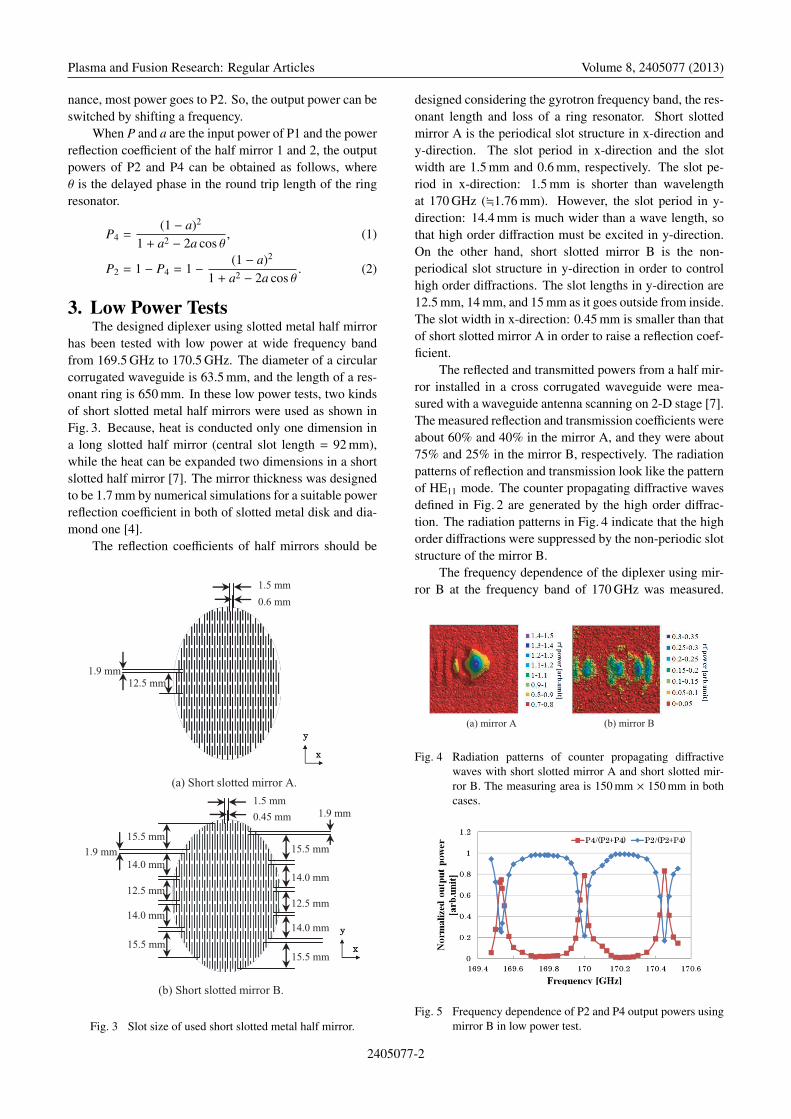
has been tested with low power at wide frequency bandfrom 169.5 GHz to 170.5 GHz. The diameter of a circularcorrugated waveguide is 63.5 mm, and the length of a res-onant ring is 650 mm. In these low power tests, two kindsof short slotted metal half mirrors were used as shown inFig. 3. Because, heat is conducted only one dimension ina long slotted half mirror (central slot length = 92 mm),while the heat can be expanded two dimensions in a shortslotted half mirror [7]. The mirror thickness was designedto be 1.7 mm by numerical simulations for a suitable powerreflection coefficient in both of slotted metal disk and dia-mond one [4].
The reflection coefficients of half mirrors should be
Fig. 3 Slot size of used short slotted metal half mirror.
designed considering the gyrotron frequency band, the res-onant length and loss of a ring resonator. Short slottedmirror A is the periodical slot structure in x-direction andy-direction. The slot period in x-direction and the slotwidth are 1.5 mm and 0.6 mm, respectively. The slot pe-riod in x-direction: 1.5 mm is shorter than wavelengthat 170 GHz (�1.76 mm). However, the slot period in y-direction: 14.4 mm is much wider than a wave length, sothat high order diffraction must be excited in y-direction.On the other hand, short slotted mirror B is the non-periodical slot structure in y-direction in order to controlhigh order diffractions. The slot lengths in y-direction are12.5 mm, 14 mm, and 15 mm as it goes outside from inside.The slot width in x-direction: 0.45 mm is smaller than thatof short slotted mirror A in order to raise a reflection coef-ficient.
The reflected and transmitted powers from a half mir-ror installed in a cross corrugated waveguide were mea-sured with a waveguide antenna scanning on 2-D stage [7].The measured reflection and transmission coefficients wereabout 60% and 40% in the mirror A, and they were about75% and 25% in the mirror B, respectively. The radiationpatterns of reflection and transmission look like the patternof HE11 mode. The counter propagating diffractive wavesdefined in Fig. 2 are generated by the high order diffrac-tion. The radiation patterns in Fig. 4 indicate that the highorder diffractions were suppressed by the non-periodic slotstructure of the mirror B.
The frequency dependence of the diplexer using mir-ror B at the frequency band of 170 GHz was measured.
Fig. 4 Radiation patterns of counter propagating diffractivewaves with short slotted mirror A and short slotted mir-ror B. The measuring area is 150 mm × 150 mm in bothcases.
Fig. 5 Frequency dependence of P2 and P4 output powers usingmirror B in low power test.
2405077-2
Plasma and Fusion Research: Regular Articles Volume 8, 2405077 (2013)
Table 1 The parameter of numerical simulations.
Fig. 6 Slot size of used long slotted metal half mirror.
Switching properties were clearly observed as shown inFig. 5.
4. Numerical SimulationsThe electromagnetic field in the diplexer has been
simulated with our developed code using FDTD method.The slotted metal plates are used as the half mirrors in-stalled in the ring resonator. Long slotted metal half mir-ror made of aluminum alloy is assumed in this simulation.The slot period is 1.5 mm (Air: Metal = 0.6 mm: 0.9 mm)as show in Fig. 6, which is smaller than a wavelength:1.76 mm at an input frequency of 170 GHz. The diame-ter of corrugated waveguides and the one turn length of aring resonator are assumed to be 21.0 mm, and 135 mm,respectively, due to the memory limitation (12 GB). Theused cell size is smaller than one tenth of a wavelength ofan input frequency.
The simulation results at the resonant frequency areshown in Fig. 7. It was confirmed that the output powerfrom P4 increases with decreasing the output power fromP2, at a resonant condition. The power loss of a metal sur-face can be calculated as the follows, where Ht is a tangen-tial component of magnetic field, Rs is a rf sheet resistance,σ is an electrical conductivity, and δ is a skin depth.
Ploss =12|Ht|2 Rs =
12|Ht|2 1
δσ. (3)
Since a magnetic field component is not given to a metalsurface of miter bend, the magnetic field component ofthe metal surface is interpolated by adjacent point’s dataas show in Fig. 8.
The tangential component of a magnetic field Ht iscomputed by a vector calculation using the magnetic fieldcomponent of the metal surface as follows.
Ht =
√√⎛⎜⎜⎜⎜⎝H2y + H2
z√2
⎞⎟⎟⎟⎟⎠2 + H2x . (4)
Fig. 7 Time evolution of normalized rf power of diplexer usingslotted metal half mirrors simulated by FDTD code at aresonant condition of ring resonator.
Fig. 8 Schema of the tangential component of a magnetic fieldHt using FDTD method.
Fig. 9 Profile of Ohmic loss on the reflected surface of the miterbend 1 installed in the ring resonator simulated by FDTDcode.
Ohmic loss at a miter bend and a slotted half mirrorinstalled in a ring resonator was simulated. It will becomeimportant to design the slotted half mirror considering heatload in high power operation. The heat load was estimatedby the numerical simulations of Ohmic loss. Since thepower loss in a ring resonator is also calculable by these
2405077-3
Plasma and Fusion Research: Regular Articles Volume 8, 2405077 (2013)
Fig. 10 Profiles of Ohmic loss on the surface of the miter bend2 in Fig. 1.
numerical simulations, it can be used also for evaluation ofthe switching operation.
The results of Ohmic loss at miter bend 1 installed inring resonator are shown in Fig. 9. The solid line indicatesthe simulation result, while the dotted line shows the the-oretical prediction without higher modes. The differencebetween both lines suggests the existence of higher modesin an oversized corrugated waveguide ring.
The simulated results of 3D Ohmic loss profile ata miter bend 2 installed in ring resonator are shown inFig. 10. It was confirmed that there was a peak value ofOhmic loss in the center of miter bend 2.
The profiles of Ohmic loss on the input-side surfaceof the half mirror 2 are shown in Fig. 11. There is a peakvalue of Ohmic loss in the center of slotted half mirror 2like HE11 mode.
The Ohmic loss on the surfaces of the miter bend 1and the miter bend 2, the inner surfaces of the half mirror1 and the half mirror 2 were estimated numerically to be0.35%, 0.26%, 0.25%, and 0.18%, respectively. Therefore,the total Ohmic loss in a ring resonator is estimated to be1.05%.
5. SummaryThe high power wide band diplexer was designed and
fabricated as a fast switching device for ECCD system.
Fig. 11 3D-Ohmic loss profile on the half mirror 2 surface in-stalled in the ring resonator.
The switching operation was confirmed by numerical sim-ulations and by low power tests. Ohmic loss at a miterbend and metal slotted half mirror installed in a ring res-onator was simulated. In the both cases, Ohmic loss wasconfirmed. There are two ideas for cooling mirrors. Oneis the thick half mirror made of OFHC with inside coolingchannels. The other is the thin half mirror made of Glidcopwith edge cooling. The heat conduction and thermal stressanalyses of the half mirror are planed in near future.
AcknowledgmentsThis work has been supported by the Grants-in-aid for
Scientific Research (c) of 22560818.
[1] Z. Chang et al., Phys. Rev. Let. 74, 4663 (1995).[2] H. Zohm, Phys. Plasmas 4, 3433 (1997).[3] W. Kasparek et al., Fusion Eng. Des. 84, 1002 (2009).[4] M. Saigusa et al., Proc. of 13th AMPERE Toulouse (2011)
p.285.[5] K. Atsumi et al., “Research and Development of High
Power Wideband Diplexer for ECCD System” Plasma Con-ference 2011, Kanazawa, 23P099-P (2011).
[6] M. Saigusa et al., Plasma Fusion Res. 7, 2405099 (2012).[7] M. Saigusa et al., /10.1016/j.fusengdes.2013.02.163, Fu-