Heriot-Watt University Research Gateway Heriot-Watt University Numerical modelling of ground borne vibrations from high speed rail lines on embankments Connolly, D.; Giannopoulos, A.; Forde, M. C. Published in: Soil Dynamics and Earthquake Engineering DOI: 10.1016/j.soildyn.2012.12.003 Publication date: 2013 Document Version Early version, also known as pre-print Link to publication in Heriot-Watt University Research Portal Citation for published version (APA): Connolly, D., Giannopoulos, A., & Forde, M. C. (2013). Numerical modelling of ground borne vibrations from high speed rail lines on embankments. Soil Dynamics and Earthquake Engineering, 46, 13-19. DOI: 10.1016/j.soildyn.2012.12.003 General rights Copyright and moral rights for the publications made accessible in the public portal are retained by the authors and/or other copyright owners and it is a condition of accessing publications that users recognise and abide by the legal requirements associated with these rights. If you believe that this document breaches copyright please contact us providing details, and we will remove access to the work immediately and investigate your claim.
Transcript
Heriot-Watt University Research Gateway
Heriot-Watt University
Numerical modelling of ground borne vibrations from high speed rail lines on embankmentsConnolly, D.; Giannopoulos, A.; Forde, M. C.
Published in:Soil Dynamics and Earthquake Engineering
DOI:10.1016/j.soildyn.2012.12.003
Publication date:2013
Document VersionEarly version, also known as pre-print
Link to publication in Heriot-Watt University Research Portal
Citation for published version (APA):Connolly, D., Giannopoulos, A., & Forde, M. C. (2013). Numerical modelling of ground borne vibrations fromhigh speed rail lines on embankments. Soil Dynamics and Earthquake Engineering, 46, 13-19. DOI:10.1016/j.soildyn.2012.12.003
General rightsCopyright and moral rights for the publications made accessible in the public portal are retained by the authors and/or other copyright ownersand it is a condition of accessing publications that users recognise and abide by the legal requirements associated with these rights.
If you believe that this document breaches copyright please contact us providing details, and we will remove access to the work immediatelyand investigate your claim.
Numerical modelling of ground borne vibrations from
high speed rail lines on embankments
*D. Connolly¹, A. Giannopoulos1 and M.C. Forde1
Abstract A three dimensional numerical model is presented capable of modelling
the propagation and transmission of ground vibration in the vicinity of high speed railways. It is used to investigate the effect of embankment constituent material on ground borne vibration levels at various distances from the track.
The model is a time domain explicit, dynamic finite element model capable of simulating non-linear excitation mechanisms. The entire model, including the wheel/rail interface is fully coupled. To account for the unbounded nature of the soil structure an absorbing boundary condition (infinite element) is placed at the truncated interfaces. To increase boundary absorption performance, the soil structure is modelled using an elongated spherical geometry.
The complex geometries associated with the track components are modelled in detail thus allowing a highly realistic simulation of force transmission from vehicle to embankment. Lastly, quasi-static and dynamic excitation mechanisms of the vehicle locomotives are described using a multi-body approach which is fully coupled to the track using non-linear Hertzian contact theory. The resulting model is verified using experimental ground borne vibration data from high speed trains, gathered through field trials. It is then used to investigate the role of embankments in the transmission of vibration. It is found that soft embankments exhibit large deflections and act as a waveguide for railway vibrations which are trapped within the structure. This results in increased vibration levels both inside the embankment and in the surrounding soil. In contrast it is found that embankments formed from stiffer material reduce vibrations in the near and far fields. 1 University of Edinburgh, School of Engineering, AGB building, Kings Buildings, Edinburgh, EH9 3JL, UK
dynamics; ABAQUS;VDLOAD; absorbing boundary condition; finite element method (FEM)
Research highlights
(a) A new 3D FE program to simulate near and far field vibration from high speed trains (b) FE Model calibrated using published high speed train experimental data (c) Train passage on soft embankments over stiff foundations generates guided waves (d) In near and far fields, soft embankments generate greater vibration than stiff ones
1. Introduction
Recent advances in mechanical, electrical and aeronautical engineering have facilitated rapid growth in railway vehicle velocities. Ground waves as generated by axle loads moving at these higher velocities have different propagation characteristics in comparison to traditional trains. The resulting vibration can travel large distances from the track causing stress to residents and possibly even structural damage [1]. To prevent civil engineering challenges prevailing as the limiting factor in the development of high speed rail transportation it is imperative to continually push the boundaries of understanding of track structural design and soil mechanics disciplines. To do so requires an in-depth knowledge of track behaviour and soil response under varying train speeds. To facilitate this Kenny [2] and Fryba [3] developed closed-form analytical solutions for ground response from moving loads. This area of research was expanded upon by Krylov et al. [4], Cai et al. [5] and more recently by Salvador et al. [6] to focus specifically on high speed train problems. One such approach was attempted by Ditzel et al. [7] where an embankment is modelled, but restrictions require that the embankment is embedded inside the soil and has perfectly vertical sides. An additional restriction is that only quasi-static excitation mechanisms can be simulated.
Although such an analytical modelling approach can be performed at relatively low computational expense, it is only valid for a narrow range of track conditions and unrealistic assumptions relating to the excitation source are often made. Therefore for high accuracy estimates such as those required for engineering design purposes, numerical modelling techniques are required. Although recent advancements in computing technology are beginning to allow larger simulations to be undertaken in shorter time periods, such technology was not available for early numerical researchers. Therefore, authors such as [8] used two dimensional finite element method (FEM) models to investigate vibration from subways. Other researchers such as Hanazato et al. [9] and Francois et al. [10] attempted to combine the advantages of 2D and 3D models through the use of 2.5D models. This thinking was extended and coupled with an infinite element absorbing boundary condition by Yang et al. [11]. Infinite elements serve to dampen outgoing waves, thus preventing their reflection against the domain boundary and resulting in a reduced
3
contamination of the domain space. Despite this, all 2D and 2.5D models models are limited in scope due to the plane stress/strain assumption. 3D models overcome these plane stress/strain limitations by explicitly modelling the third dimension. Galvin et al. [12] uses a coupled FEM/BEM (boundary element method) approach where the track is modelled using FEM and the unbounded domain is accounted for by BEM. The FEM sub-model allows for highly accurate modelling of the track and can account for changes in track geometry and dynamic excitation. Despite this, the BEM sub-model is dependant on the Green’s function of the medium. As the Green’s function is used to determine the fundamental solution of the differential equations used to describe wave propagation in the medium, only a narrow range of soil characteristics can be modelled. Similar challenges face methods proposed by O’Brien et al. [13] and Chebli et al. [14]. A pure FEM solution is utilised by Banimahd et al. [15] and Kouroussis et al. [16]. A challenge presented by this approach is that absorbing boundary conditions must be implemented at model boundaries to prevent spurious waves contaminating the solution. Kouroussis employed ABAQUS’s infinite element library to absorb such waves. Absorption performance is enhanced for excitations at the centre of the sphere by modelling the soil as a spherical domain. Despite this, the performance of absorbing boundary conditions decreases as the distance between excitation and boundary is reduced. Therefore when the excitation location deviates from the central position, performance degrades. A disadvantage of ABAQUS’s modelling capabilities is that it is difficult to simulate displacement defined loads, which are pivotal in modelling a realistic contact condition between wheel and rail. Powrie et al. [17] and Hall et al. [18] employ static and moving point loads respectively but the weakness of these techniques is that they are unable to simulate dynamic excitation effects. Kouroussis et al. [19] proposes an alternative solution by separating the modelling approach into two sub-models, one for the multibody vehicle simulation and one for soil modelling. Although this approach is capable of simulating quasi-static and dynamic excitation mechanisms, the models are solved independently meaning that only first order interaction effects are accounted for.
Excluding analytical and 2D FEM approaches, literature relating to 3D numerical modelling of railway embankment structures is scarce. Therefore this paper outlines the development of a railway vibration prediction model. This model is an explicit time domain, 3D, dynamic FEM model capable of simulating non-linearities at the wheel/rail interface. All model components are fully coupled including the wheel and rail. This allows both quasi-static and dynamic excitations to be modelled. Absorbing boundary performance is increased through the use of an elongated spherical domain. Experimental data used for model validation and parameter selection is taken from [19]. The resulting model is then used to analyse the role of embankment stiffness in the propagation and transmission of railway vibrations.
2. Modelling approach 2.1 Track modelling
4
Track geometry and material properties were modelled in accordance
with the UK Channel Tunnel Rail Link [20] and International union of Railways [21] specification. Fifty metres of track was modelled using 77 sleepers placed at 0.65m centres. The model was symmetrical in the track direction, so only half of all track components and half of the supporting soil was modelled.
The rail was modelled as a continuously welded solid rectangular section with dimensions 0.153m x 0.078m, laid at 1.435m gauge. Timoshenko beam elements 0.1m in length were used in preference to Euler-Bernoulli due to their additional degrees of freedom. This approach allowed shear forces to be modelled, thus providing a more accurate transmission of high frequency forces into the track structure.
Each sleeper was formed from reinforced concrete with dimensions 0.242m x 0.2m x 2.42m. The sleeper sections were supported by a ballast layer, a subballast layer and a subgrade layer as shown in Figure 1. Track material properties are provided in Table 1.
All track components (excluding the rail) were modelled using 8 noded solid cuboid elements, approximately 0.2m in length along each axis. The edges of the ballast, subballast and subgrade layers located at the ends of the track were terminated with a layer of infinite elements. This prevented reflections occurring inside the track structure due to the truncation of components. 2.2 Soil modelling
2.2.1 Soil material properties
Soil properties of the test site were found using a spectral analysis of surface waves (SASW) technique by Kouroussis et al. [19]. This involved exciting the ground using a 50kg weight and recording the seismic response using low frequency (4.5Hz) geophones. Then a dispersion curve was constructed and the resulting wave speeds and layer thicknesses determined using a Haskell-Thomson approach [22], [23].
The soil was modelled as a stratified linear elastic material consisting of three layers with varying material properties as defined in Kouroussis et al. [19]. The uppermost layer consisted of 2.7m of silt and the second layer consisted of 3.9m of clay. The third layer consisted of an 8.4m layer of sand, the bottom of which was bounded by an absorbing boundary condition to simulate an unbounded domain. A summary of soil material properties is found in Table 1. A uniform stiffness proportional Rayleigh damping value of β=0.0004s was assumed for all layers in accordance with Kouroussis et al. [19]. Although this implementation imposed a reduced simulation timestep criterion, its inclusion was essential to accurately model energy dissipation in the soil layers.
5
Figure. 1. Track material properties
2.2.2 Absorbing boundary solution
The soil structure was modelled as a 60m x 25m x 15m solid section. To
prevent reflections from the edge of the truncated domain, absorbing boundaries [24], [25] were implemented using the equations:
ωρσ &pca= (1)
υρτ &scb= (2)
Where σ represents normal stresses, τ is shear stresses, ω is the normal velocity at the boundary and υ is the tangential velocity at the boundary. The dimensionless absorption parameters, a and b were set equal to 1 thus maximising body wave absorption.
These boundaries are also known as one wave equations and act to damp the amplitude of outgoing waves using decay functions. Therefore by the time the outgoing wave impinges on the extremity of the infinite element layer it has reduced amplitude, thus simulating an infinitely long medium.
Although such boundaries offer high absorption for waves impacting the boundary at high incidence angles, performance is reduced for highly non-incident waves. Due to the complexity of seismic wave propagation, depending on boundary geometry, a high percentage of waves can impinge at non-incident angles to the boundary. This is because the primary seismic waves (compressional, shear and Rayleigh) propagate with different characteristics. Rayleigh waves differ because their energy decreases rapidly with depth and is dependant upon excitation frequency. Figure 2 shows a typical compressional, shear and Rayleigh wave distribution.
50mSubgrade
Subballast
Ballast
E = 1
2e7 (Pa)
v = 0
.35
p = 2
100 (kg/m
3)
E = 3e8 (P
a)
v = 0.35
p = 2200 (k
g/m3)
E = 1e8 (Pa)
v = 0.35
p = 1800 (kg/m
3)
Sleepers
E = 3e10 (Pa)
v = 0.25
p = 2400 (kg/m3)
Rails
E = 2.1e11 (Pa)
v = 0.25
p = 7900 (kg/m3)
6
Figure 2. Seismic wave distribution (redrawn from [26])
In an attempt to overcome this limitation, Kouroussis et al. [16]
developed a boundary with spherical geometry, which was shown to have greater absorption properties. Increased absorption is achieved because the wave patterns of the propagating waves more closely match the domain geometry. Therefore a higher percentage of waves arrive incident to the boundary. Some small reflections still persist and are caused by Rayleigh waves because the viscous boundary performs less efficiently in comparison to body waves. Although greater absorption is found for excitations at the centre of such a model, performance drops with increasing deviation from this central location. As the distance between source and boundary decreases, fewer waves arrive at an incident angle to the boundary and thus absorption is less efficient. This is undesirable for moving load problems where the source location changes rapidly. Therefore the domain geometry was modified and an elongated spherical domain was developed (Figure 3). This creates a scenario where, for a moving load travelling in a straight line such as for the case of a train, improved absorption performance is achieved for a greater combination of spatial locations. This is because for the entire length of track, the viscous boundary geometry closely matches the shape of wave propagation. Also, at the start and end of the track, the boundary closely matches the wave propagation. Therefore, overall a higher percentage of wave arrivals will be incident to the finite/infinite element boundary. To implement this boundary condition ABAQUS’s infinite element library was utilised. Infinite elements require an alternative node numbering notation in comparison to regular elements. Therefore three individual MATLAB scripts were developed capable of directly editing the ABAQUS input file. These scripts were used to redefine the nodal numbering system, project the outer infinite nodes to their required positions and to align the elements of each particular sub-section of the overall geometry.
Shear wave
Compressional wave
Rayleigh
wave
Damping
Horiz
compVert
comp
Excitation
-- + +
++
7
Figure 3. Symmetrical soil finite/infinite element solution
2.3 Vehicle modelling
The articulated vehicle was based upon a Thalys high speed train as commonly found operating in Germany, France and Belgium. The train length was 200m and consisted of 11 carriages (two traction cars and nine passenger cars).
Figure 4. Vehicle modelling - Typical ½ Thalys car (left), simplified Thalys model
(right)
In a similar manner to the track components, the vehicle was symmetrical in the longitudinal direction. In addition, it was assumed that each car was also symmetrical in the direction of vehicle movement meaning each car could be divided into two separate spring-damper systems. This approach reduces computational demands and has been shown to produce similar results to modelling the carriages as a single body [12]. Each quarter carriage was thus modelled using a multi-body spring-damper system where the carriage mass,
8/cc mm = and the bogie mass, 4/bb mm = . The cars and bogies were modelled
as rigid bodies and were connected via a primary and secondary suspension system (Figure 4). This resulted in the following equations of motion:
Car (mw)
Bogie (mb)
Wheel
(mw)
K2
K1
C2
C1
KH
8
+=
+
−−+−
−+
−−+−
−
wrw
b
c
w
b
c
w
b
c
w
b
c
w
b
c
Fgm
gm
gm
u
u
u
m
m
m
u
u
u
cc
cccc
cc
u
u
u
kk
kkkk
kk
&&&&&&
&&&
00
00
00
0
0
0
0
11
1212
22
11
1212
22
(3) For a typical Thalys high speed train passenger car: =cm 57,000 kg, =bm 11,200
The wheel and the rail were coupled using a non-linear Hertzian contact spring [27]. This allowed the force exerted from the train wheels at a given timestep to be a function of the wheel displacement and rail displacement. If the wheel was not touching the rail then no force was exerted:
( ) ( )( ) 00
0,5.1
>+−=<+−−−=
ruuF
ruuruukF
rwwr
rwrwHwr (4)
=wrF represents the wheel/rail interaction force and =wrK is the Hertzian
constant which is related to the geometry and material properties of the wheel and rail. A value of HK = 9.4e10 N/m1.5 was assumed.
r represents the rail surface irregularity. This accounts for geometric defects caused by train operational effects such as train braking and track debris. Irregularities introduce high frequency excitation into the system in addition to the low frequency content generated due to the sleeper spacing excitation frequencies. This combination of quasi-static and dynamic excitation has been shown to play an important role in the propagation of railway vibration [28], [29], [30].
The irregularity was considered to be periodic in nature and to follow the form:
( ) ( )xwAxr rsin= (5)
Where x is distance from the initial position, A is the amplitude of the irregularity and rw is the circular spatial frequency of the irregularity ( rw = 62.8
rad/s, A = 0.005m, [31]). 2.4 Commercial FEM software implementation
ABAQUS moving loads are typically defined using the VDLOAD FORTRAN subroutine. This subroutine defines the distribution of non-uniform load magnitudes as a function of time and position, at a set of predefined integration points. Despite this, it is not possible to directly implement a displacement
9
defined load in this manner because VDLOAD prohibits access to the real time displacement values of the loading surface.
To overcome this, an additional subroutine (VUFIELD) was used to provide VDLOAD with these displacement values. Typically VUFIELD is used to define predefined field variables (e.g. accelerations, velocities or displacements) at model nodes but in this case it was used to record these values for use within the VDLOAD subroutine. This facilitated coupling between the wheel and rail, an essential requirement for defining the non-Hertzian contact condition. Once the rail displacement was obtained, the equations of motion for the cars, bogies and wheels were computed within the VDLOAD subroutine in a staggered manner with respect to the ABAQUS solver. An explicit central difference integration scheme [32] was used:
( )( )11
11
1
1
5.0
5.0
++
+−
+
+
+∆+=−−=
∆+∆+=
tttt
ttextt
tttt
t
tt
AAVV
KXCXFMA
XVXX
(6)
Where X, A and V are displacement, acceleration and velocity vectors respectively. Fext is the external force vector and ∆t is the timestep. The mass matrix was lumped, meaning the system of equations was solved without matrix inversion, thus reducing the computational requirements. The integration scheme closely followed that used within the ABAQUS solver thus making it trivial to ensure that the minimum timestep threshold was met simultaneously for both staggered schemes.
3. Validation with experimental data
Model performance was analysed by comparing vibration results to field trails collected in Belgium on the Brussels to Paris high speed line [19]. The timestep was fixed at 1.6x10⁻⁵s and a single passage of a 200m long, 265km/h Thalys high speed train over the 50m track length was approximately 2.8s. Material properties are summarised in Table 1.
Due to the large computational effort required to compute such simulations, ABAQUS’s native MPI libraries were utilised and processing was executed in parallel using two Intel Xeon E5645 six-core processors [33].
Figure 5 shows a comparison between simulation results and field experiments. Predicted soil response has a high correlation of peak particle velocity (PPV) with the experimental result. The response to the passage of each wheel-set is visible and similar in timing, shape and magnitude. Similarly, ground response to the heavier traction cars at the front and rear ends of the Thalys train has been simulated effectively. Despite this, while accurately modelling the magnitude of the positive velocities, the model appears to slightly overestimate the downward velocities.
0 0.5 1 1.5 2 2.5 3−0.4
−0.3
−0.2
−0.1
0
0.1
0.2
0.3
0.4
Time (s)
Vel
ocity
(m
m/s
)
Field experimentNumerically predicted
11
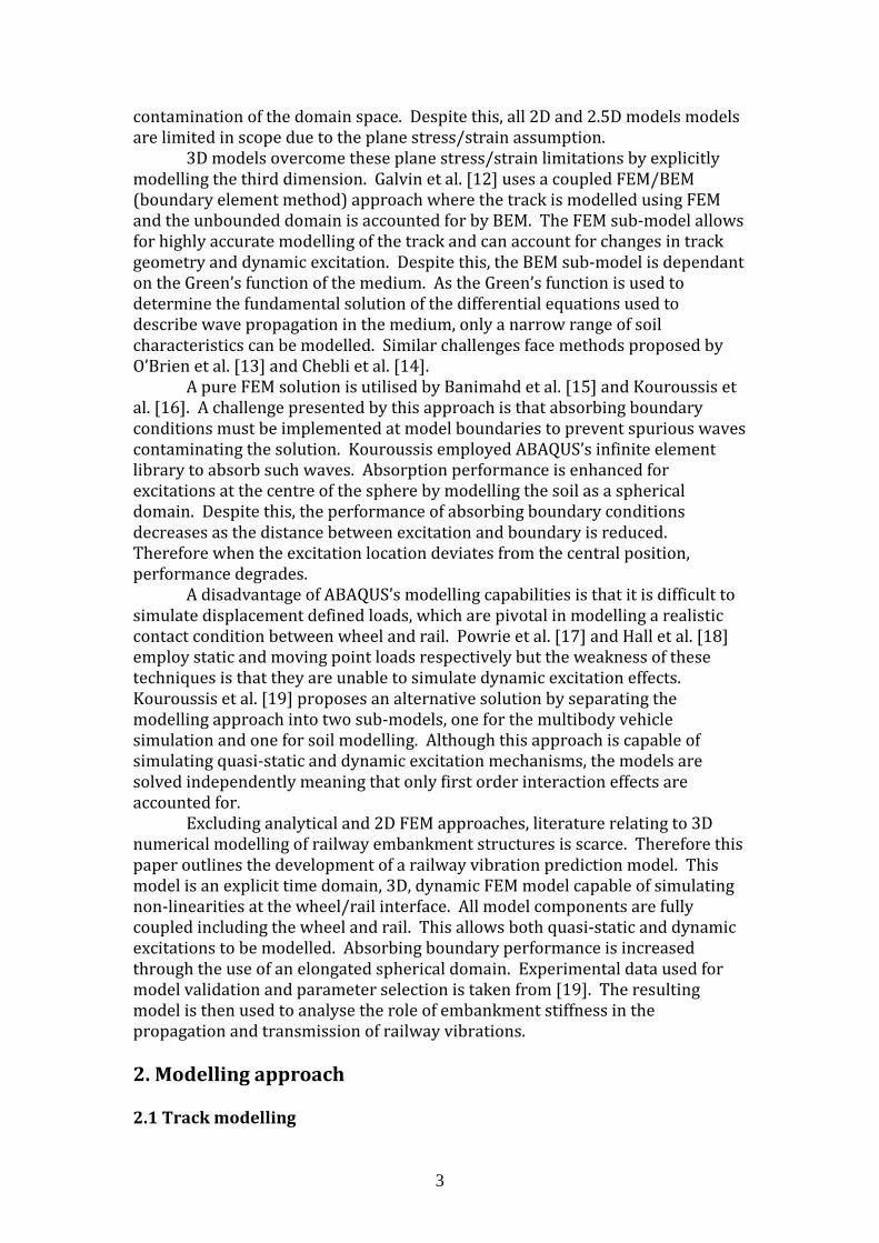
Figure 6. Attenuation of PPV
Figure 6 shows the attenuation of PPV with increasing distance from the
track. There are strong similarities between the magnitudes and gradients of both lines and the correlation between results is 0.8. Therefore the numerical model is capable of effectively simulating PPV at both near and far distances from the track.
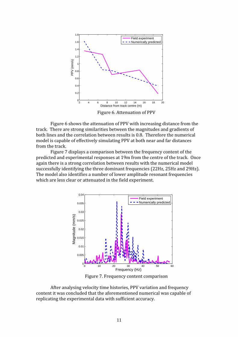
Figure 7 displays a comparison between the frequency content of the predicted and experimental responses at 19m from the centre of the track. Once again there is a strong correlation between results with the numerical model successfully identifying the three dominant frequencies (22Hz, 25Hz and 29Hz). The model also identifies a number of lower amplitude resonant frequencies which are less clear or attenuated in the field experiment.
Figure 7. Frequency content comparison
After analysing velocity time histories, PPV variation and frequency
content it was concluded that the aforementioned numerical was capable of replicating the experimental data with sufficient accuracy.
2 4 6 8 10 12 14 16 18 200
0.2
0.4
0.6
0.8
1
1.2
1.4
1.6
1.8
Distance from track centre (m)
PP
V (
mm
/s)
Field experimentNumerically predicted
0 10 20 30 40 50 600
0.005
0.01
0.015
0.02
0.025
0.03
0.035
0.04
Frequency (Hz)
Mag
nitu
de (
mm
/s)
Field experimentNumerically predicted
12
4. Numerical results
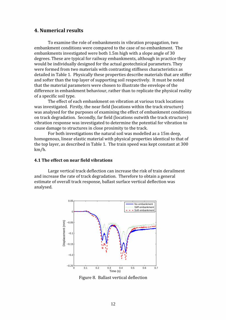
To examine the role of embankments in vibration propagation, two embankment conditions were compared to the case of no embankment. The embankments investigated were both 1.5m high with a slope angle of 30 degrees. These are typical for railway embankments, although in practice they would be individually designed for the actual geotechnical parameters. They were formed from two materials with contrasting stiffness characteristics as detailed in Table 1. Physically these properties describe materials that are stiffer and softer than the top layer of supporting soil respectively. It must be noted that the material parameters were chosen to illustrate the envelope of the difference in embankment behaviour, rather than to replicate the physical reality of a specific soil type. The effect of each embankment on vibration at various track locations was investigated. Firstly, the near field (locations within the track structure) was analysed for the purposes of examining the effect of embankment conditions on track degradation. Secondly, far field (locations outwith the track structure) vibration response was investigated to determine the potential for vibration to cause damage to structures in close proximity to the track. For both investigations the natural soil was modelled as a 15m deep, homogenous, linear elastic material with physical properties identical to that of the top layer, as described in Table 1. The train speed was kept constant at 300 km/h. 4.1 The effect on near field vibrations
Large vertical track deflection can increase the risk of train derailment and increase the rate of track degradation. Therefore to obtain a general estimate of overall track response, ballast surface vertical deflection was analysed.
Figure 8. Ballast vertical deflection
0 0.1 0.2 0.3 0.4 0.5 0.6 0.7−0.25
−0.2
−0.15
−0.1
−0.05
0
0.05
Time (s)
Dis
plac
emen
t (m
m)
No embankmentStiff embankmentSoft embankment
13
The passage of each individual wheel is clearly visible in Figure 8. Vertical deflection for the case of no embankment is less than the soft embankment but greater than the case of the stiff embankment. Similarly, there is a strong contrast in maximum deflection levels between the stiff and soft cases, with the peak displacement for the soft embankment being 63% greater. This increased deflection has two primary causes. Firstly the softer embankment has less compressional strength thus allowing the same load to penetrate further into the material. Secondly, the embankment to soil material interface has a seismic reflection coefficient (Rc) (Equation 5) of 0.28 thus causing wave energy to be reflected from the natural soil surface back into the embankment, thus trapping energy within its structure. This causes a waveguide effect. The opposite is observed for the stiff case because the embankment-soil interface has a reflection coefficient of -0.55, thus encouraging high levels of energy transmission from embankment to soil.
Figure 9. Seismic reflection/transmission
2211
2211
υρυρυρυρ
+−
=cR (7)
Where: =1ρ density of upper material
=1υ wave velocity in upper material
=2ρ density of lower material
=2υ wave velocity in lower material
4.2 The effect on far field vibrations
Far field vibrations are important for determining the probability of structural damage to nearby buildings. Therefore in accordance with DIN 4150 [34], PPV criteria were used to analyse vibration intensity at varying distances from the embankment.
Material 1
Material 2
Re!ected
wave
Transmitted
wave
Wave
arrival
14
Figure 10. The effect of embankment material on far field response
Figure 10 shows vibration levels at seven equally spaced receivers,
ranging between 2-14m from the embankment footing. As expected, PPV decreases with distance from the embankment. Despite this, when embankment stiffness is increased from soft to stiff, an average decrease in PPV of 72% in the surrounding soil is observed. Furthermore, a stiff embankment causes a significant decrease in vibration propagation while the soft embankment causes an increase of similar magnitude. Therefore it can be concluded that the addition of an embankment formed from a stiffer material than the underlying soil reduces far field vibration. Similarly, an embankment that is soft in comparison to the surrounding soil increases far field vibrations.
5 Conclusions
A 3D finite element model has been developed capable of predicting railway vibrations in the presence of an embankment. This model utilises a modified spherical absorbing boundary condition for enhanced performance and a staggered integration scheme to couple track and train models. It has been verified using experimental data collected on a high speed line between Paris-Brussels. It was subsequently used to investigate the effect of embankment stiffness on vibration propagation at various distances from the track. It was found that depending on the softness of the embankment constituent material, the embankment may act as a waveguide thus trapping energy within it. This can result in a large amplification of vibrations within the track structure and in the surrounding soil. Conversely, it is found that increasing embankment stiffness results in a decrease in vibration at all distances from the track.
Acknowledgements
The authors acknowledge the provision of facilities by the University of
Edinburgh. Valuable discussions with Professor Ian Main, Geosciences, University of Edinburgh and Professor Peter Woodward, Heriot-Watt University
2 4 6 8 10 12 140.1
0.2
0.3
0.4
0.5
0.6
0.7
0.8
Distance from embankment (m)
Pea
k pa
rtic
le v
eloc
ity (
mm
/s)
No embankmentStiff embankmentSoft embankment
15
are acknowledged. Financial support was provided by EPSRC grant EP/H029397/1.
References
[1] J. Rainer and G. Pernica, Effect of train-induced vibrations on houses - a case study, in Symposium/workshop on serviceability of buildings
(movements, deformations, vibrations), 1988, pp. 603–614.
[2] J. Kenny, Steady-state vibrations of beam on elastic foundation for moving load, Journal of Applied Mechanics1, vol. 76, pp. 359–364, 1954.
[3] L. Fryba, Vibration of Solids and Structures Under Moving Loads. Groningen, The Netherlands: Noordhoff International Publishing, 1972.
[4] V. Krylov, A. Dawson, M. Heelis, and A. Collop, Rail movement and ground waves caused by high-speed trains approaching track-soil critical velocities, Proceedings of the Institution of Mechanical Engineers, Part F:
Journal of Rail and Rapid Transit, vol. 214, no. 2, pp. 107–116, Jan. 2000.
[5] Y. Cai, Z. Cao, H. Sun, and C. Xu, Effects of the dynamic wheel–rail interaction on the ground vibration generated by a moving train, International Journal of Solids and Structures, vol. 47, no. 17, pp. 2246–2259, Aug. 2010.
[6] P. Salvador, J. Real, C. Zamorano, and A. Villanueva, A procedure for the evaluation of vibrations induced by the passing of a train and its application to real railway traffic, Mathematical and Computer Modelling, vol. 53, no. 1–2, pp. 42–54, Jan. 2011.
[7] A. Ditzel and G. Herman, The influence of a rail embankment on the vibrations generated by moving trains, Journal of Sound and Vibration, vol. 271, no. 3–5, pp. 937–957, Apr. 2004.
[8] T. Balendra, K. H. Chua, K. W. Lo, and S. Lee, Steady-state vibration of subway-soil-building system, J. Eng. Mech., ASCE, vol. 115, no. 1, pp. 145–162, 1989.
[9] Hanazato, T, K. Ugai, M. Mori, and R. Sakaguchi, Three-dimensional analysis of traffic-induced ground vibrations, Journal of Geotechnical and
Geoenvironmental Engineering, vol. 117, no. 8, pp. 1133–1151, 1991.
[10] S. François, M. Schevenels, P. Galvin, G. Lombaert, and G. Degrande, A 2.5D coupled FE–BE methodology for the dynamic interaction between longitudinally invariant structures and a layered halfspace, Computer
Methods in Applied Mechanics and Engineering, vol. 199, no. 23–24, pp. 1536–1548, Apr. 2010.
16
[11] Y. Yang, Train-induced wave propagation in layered soils using finite/infinite element simulation, Soil Dynamics and Earthquake
Engineering, vol. 23, no. 4, pp. 263–278, Jun. 2003.
[12] P. Galvin, A. Romero, and J. Domínguez, Fully three-dimensional analysis of high-speed train–track–soil-structure dynamic interaction, Journal of
Sound and Vibration, vol. 329, no. 24, pp. 5147–5163, Nov. 2010.
[13] J. O’Brien and D. Rizos, A 3D BEM-FEM methodology for simulation of high speed train induced vibrations, Soil Dynamics and Earthquake Engineering, vol. 25, pp. 289–301, Apr. 2005.
[14] H. Chebli, R. Othman, D. Clouteau, M. Arnst, and G. Degrande, 3D periodic BE–FE model for various transportation structures interacting with soil, Computers and Geotechnics, vol. 35, no. 1, pp. 22–32, Jan. 2008.
[15] M. Banimahd, J. Kennedy, P. Woodward, and G. Medero, Behaviour of train – track interaction in stiffness transitions, Proceedings of the Institution of
Civil Engineers, vol. 1, no. 2006, pp. 1–10, 2010.
[16] G. Kouroussis, O. Verlinden, and C. Conti, Ground propagation of vibrations from railway vehicles using a finite/infinite-element model of the soil, Proceedings of the Institution of Mechanical Engineers, Part F: Journal of
Rail and Rapid Transit, vol. 223, no. 4, pp. 405–413, Jul. 2009.
[17] W. Powrie, L. Yang, and C. Clayton, Stress changes in the ground below ballasted railway track during train passage, Proceedings of the Institution
of Mechanical Engineers, Part F: Journal of Rail and Rapid Transit, vol. 221, no. 2, pp. 247–262, Jan. 2007.
[18] L. Hall, Simulations and analyses of train-induced ground vibrations in finite element models, Soil Dynamics and Earthquake Engineering, vol. 23, pp. 403–413, Apr. 2003.
[19] G. Kouroussis, O. Verlinden, and C. Conti, Free field vibrations caused by high-speed lines: Measurement and time domain simulation, Soil Dynamics
and Earthquake Engineering, vol. 31, no. 4, pp. 692–707, Apr. 2011.
[20] N. O’Riordan and A. Phear, Design and construction of ballasted track formation and subgrade for high speed lines, in Proceedings of the
International Conference of “Railway Engineering-2001,” Proc 4th Int Conf., Commonwealth Institute, London, Engineering Technics Press, UK, CD-Rom, ISBN 0-947644-45-8.
[21] International union of Railways, UIC code 719R: Earthworks and trackbed layers for railway lines, UIC, Paris, France, 1994.
[22] S. Nazarian and D. Milind, Automated surface wave method: Field testing, journal of Geotechnical Engineering, vol. 119, no. 7, pp. 1094–1111, 1993.
17
[23] D. Yuan and S. Nazarian, Automated surface wave method: Inversion technique, journal of Geotechnical Engineering, vol. 119, no. 7, pp. 1112–1126, 1993.
[24] J. Lysmer and R. Kuhlemeyer, Finite dynamic model for infinite media, Journal of the Engineering Mechanics, no. 95(EM4), pp. 859–877, 1969.
[25] G. Kouroussis, O. Verlinden, and C. Conti, Finite-Dynamic Model for Infinite Media: Corrected Solution of Viscous Boundary Efficiency, Journal of
Engineering Mechanics, no. July, pp. 509–511, 2011.
[26] C. Haosheng and L. Shihan, “Inelastic damages by stress wave on steel surface at the incubation stage of vibration cavitation erosion,” Wear, vol. 266, no. 1–2, pp. 69–75, Jan. 2009.
[27] K. Johnson, Contact mechanics. Cambridge, UK: Cambridge University Press, 1985.
[28] X. Sheng, C. J. C. Jones, and D. J. Thompson, A comparison of a theoretical model for quasi-statically and dynamically induced environmental vibration from trains with measurements, Journal of Sound and Vibration, vol. 267, pp. 621–635, 2003.
[29] G. Lombaert and G. Degrande, Ground-borne vibration due to static and dynamic axle loads of InterCity and high-speed trains, Journal of Sound and
Vibration, vol. 319, no. 3–5, pp. 1036–1066, Jan. 2009.
[30] L. Auersch, The excitation of ground vibration by rail traffic: theory of vehicle-track-soil interaction and measurements on high-speed lines, Journal of Sound and Vibration, vol. 284, no. 1–2, pp. 103–132, Jun. 2005.
[31] M. Banimahd, Train-track systems: A geotechnical perspective, PhD thesis, Heriot-Watt University, 2008.
[32] I.M. Smith and D.V. Griffiths, Programming the finite element method. 4th edition, John Wiley & Sons, Chichester, New York, (2004)
[33] O. Richards and M. Baker, GridPP and the Edinburgh Compute and Data Facility, in UK All Hands Meeting, 2008.
[34] Deutsches Institut fur Normung, DIN 4150-3: Structural vibrations—part 3: effects of vibration on structures, 1999.