Abstract Landmine threats play a crucial role in the designof armored personnel carriers. Therefore, a reliable blastsimulation methodology is valuable to the vehicle designdevelopment process. The first part of this study presentsa parametric approach for the quantification of the importantfactors such as the incident overpressure, the reflected over-pressure, the incident impulse, and the reflected impulse forthe blast simulations that employ the Arbitrary Lagrangian-Eulerian formulation. The effects of mesh resolution, meshtopology, and fluid-structure interaction (FSI) parameters arediscussed. The simulation results are compared with the cal-culations of the more established CONventional WEaPons(CONWEP) approach based on the available experimentaldata. The initial findings show that the spherical topologyprovides advantages over the Cartesian mesh domains. Fur-thermore, the FSI parameters play an important role whencoarse Lagrangian finite elements are coupled with fineEulerian elements at the interface. The optimummesh topol-ogy and the mesh resolution of the parametric study are thenused in the landmine blast simulation. The second part of thestudy presents the experimental blast response of an armoredvehicle subjected to a landmine explosion under the frontleft wheel in accordance with the NATO AEP-55 Standard.The results of the simulations show good agreement with theexperimental measurements.
Undercarriage landmine blasts cause a significant threat tooccupant safety in armoredpersonnel carriers. Theblastwaveinteraction with armored plates in the undercarriage is animportant factor in the design process.
Experimental studies provide valuable insight to the per-formance of armored vehicles subjected to landmine blast.Some measures of performance include the resistance ofthe undercarriage against tearing of the armor plates, fail-ure of the structural welds, and high accelerations of thefootrest plate used by the occupants. Landmine blast exper-iments that involve the testing of the full vehicle are costlyand time consuming, while numerical simulations provide afaster alternative to measure the vehicle performance underblast loads. The blast resistant undercarriage armor design isan iterative process that is shaped by the successive use ofnumerical simulations.
There are two major approaches for modeling blast loads.The first approach involves the use of empirical equationsobtained from blast experiments. This is referred to as theCONWEP method (CONventional WEaPons). This tech-nique is suitable for simulating structural members directlyexposed to the blast wave, without any obstructions orshadowing effects. The second approach is the ArbitraryLagrangian-Eulerian (ALE) technique that requires themod-eling of the surrounding air with a volumetric mesh aroundthe target structure. It allows the application of the Navier-Stokes fluid dynamics equations for simulating the blastwave
propagation. The coupling algorithm provides the interactionof the blast wave with the target structure. However, the ALEsimulations lead to an increase in computational cost whencompared with the CONWEPmethod. Furthermore, calibra-tion of the ALE parameters is a time consuming process.
The first part of the study presents the calibration of theALE approach by comparing the overpressure and impulseresults with the CONWEP method for a target flat platedirectly facing an explosive charge. The topology of the sur-rounding air is modeled using a uniform Cartesian mesh aswell as a spherical mesh.
The advantage of the spherical topology is that the flowof the mesh lines is perpendicular to the direction of theblast wave propagation for a spherical charge. This type ofmesh topology yields a higher level of accuracy for the ALEadvection algorithm because the close-in shape of the blastwave is similar to the geometry of the charge. However, itshould be noted that the blast wave formation will not bebest represented with a spherical mesh topology for non-spherical shaped charges in the close-in range. The increasein simulation accuracy due to the employment of highermeshresolutions is illustrated for both the Cartesian and the spher-ical topologies.
The second part of the study presents the experimentalresults for a full-scale blast test of an armored personnelcarrier subjected to undercarriage landmine explosion. Alandmine with a cylindrical geometry is encased in a rec-tangular steel pot planted under the front left wheel of thevehicle in accordance with the NATO AEP-55 Standard [1].Displacement, velocity and acceleration data on the crewcompartment are collected. The experimental results arecompared with the numerical LS-Dyna simulation employ-ing the ALE method. The optimum simulation parametersobtained from the flat plate study are used in the ALE simula-tion of the landmine explosion. The spherical mesh topologyis employed for the air surrounding the vehicle. It is evi-dent that the cylindrical shape of the charge and the blastwave reflections from the vehicle undercarriage result in anon-spherical blast wave formation for the close-in range inthe vicinity of the front wheel where the detonation takesplace. However, for the spherical mesh resolution used in thenumerical study the computed displacements in the cabinnearest to the blast location are in good agreement with theexperimental measurements.
2 Literature review
The most common mesh topology used in ALE type of blastsimulations is the Cartesian geometry in which the Euleriandomain for the surrounding air is modeled with hexahedralelements with orthogonal mesh lines. However, there area limited number of studies in the literature with spheri-
cal Eulerian mesh topologies. Chafi et al. [2] investigatedthe incident overpressure and the reflected overpressure ona circular armor plate for C-4 and TNT types of explo-sives by utilizing the ALE formulation of the LS-Dyna code.Their model reflects a spherical mesh topology. Slavik [3]employed amapping technique to couple the CONWEP blastloads to the ALE domain that utilizes various mesh resolu-tions. Kwasniewski et al. [4] examined the effects of differentmesh resolutions and standoff distances on the reflectedoverpressure, and compared results with the available exper-iments. They concluded that the ALE simulation is highlysensitive to the mesh resolution used. Kilic [5] investigatedthe effect of the mesh resolution on the blast simulations ofprotective perimeter walls using the ALE approach of theLS-Dyna code. Kilic and Smith [6,7] investigated the blastresponse of deformable and rigid structural walls for the pro-tection of critical buildings by employing the CONWEP andthe ALE approaches of the LS-Dyna code. They used theCONWEP approach to investigate the response of an indi-vidual blast wall, and used the ALE approach to simulatethe shadowing effects of blast walls placed between the highexplosive and the target structure for various standoff dis-tances.
Erdik et al. [8] examined the effects of landmine explo-sives detonated in a steel pot placed under the V-shapedhull of an armored vehicle using the ALE formulation. Theyreported that the numerical results were in agreement withthe experimental results.
Yin et al. [9] studied modeling the blast loads on build-ing structures. They employed the ALE approach with thespherical mesh topology to model the high explosive andthe surrounding air with one-to-one node transition at theboundary. They suggested that fine mesh resolutions shouldbe used in the ALE method to provide accurate results forthe incident and the reflected overpressures.
Zakrisson et al. [10] presented the numerical and experi-mental results of deformable steel plates subjected to explo-sives confined in a steel pot. They used the ALE formulationwith differentmesh resolutions and compared the resultswiththe CONWEP approach. They concluded that the CONWEPapproach was not suitable for representing the confinementeffects of the explosive placed in the pot. They concludedthat the CONWEP approach cannot accurately represent theblast wave formation for explosives with geometries otherthan the spherical or the hemispherical shapes.
TheCONWEPapproach requires the least amount of com-putational resources and includes the effects of the gaseousproducts of the explosion during the afterburning processafter detonation. The CONWEP approach provides moreaccurate results in the near field range compared to the ALEtechnique; however, it cannot accurately represent the blastwave formation for non-spherical high explosive geometries.The ALE approach is computationally intensive but can sim-
123
Numerical simulation of armored vehicles subjected to undercarriage landmine blasts 451
ulate the confinement effect for encased explosives, the effectof the shape of the high explosive, and can handle the blastwave reflections on complex target surfaces as well as blastshadowing effects when obstacles exist between the highexplosive and the target structure. This paper aims to presentthe effects of mesh resolution as well as mesh topology onthe blast simulation results using the ALE approach.
3 Methodology
There are twomain approaches to simulate the dynamic pres-sure loading on target structures in the commercial finiteelement code LS-Dyna. The first method is based on apply-ing a pre-defined pressure function directly on the nodes ofthe finite element model of the target structure. The pre-defined pressure-time history loading function is establishedupon the empirical equations obtained from experimentalblast studies. Such empirical equations are available in theU.S. ArmyManual TM 5-1300 [11]. A numerical standalonecomputer program, CONWEP was developed by the UnitedStates Army Corps of Engineers Protective Design Centerthat incorporates the empirical equations of the ArmyDesignManual TM 5-855-1 [12]. The same equations of the CON-WEP program were also implemented in the LS-Dyna codefor simulating blast loading of structures through the use ofthe *LOAD_BLAST keyword function [13,14].
The other alternative method available in the LS-Dynacode is the ALE approach. The medium between the highexplosive and the structure is explicitly modeled with a volu-metric mesh using the Eulerian approach. The Eulerian meshis divided into twoparts; the fluidmediumand the high explo-sive that share common nodes. The physical properties of airand the high explosive are assigned to the elements that repre-sent the fluid medium and the explosive device, respectively.When the detonation process takes place, the blast wavetravels at the user-input detonation velocity inside the meshdomain of the explosive material. The blast wave is inducedin the fluid medium when the wave reaches the shared nodesof the high explosive-fluid boundary. The blast wave thentravels in the fluid domain. The interaction between theblast wave and the target structure is provided using the*CONSTRAINED_LAGR_IN_SOLID keyword function inthe LS-Dyna code. The fluid-structure interaction method isbased on a penalty formulation [15]. The target structure ismodeled by a Lagrangian mesh that does not share nodeswith the Eulerian fluid domain. This allows the analyst toinsert any arbitrary Lagrangian mesh of the target structureinside the volumetric Eulerian fluid mesh.
The CONWEP method is used for the calibration of theblast load parameters of the ALE approach for the TNT typeof high explosive material investigated in this study. Whenexplosives of other types are employed, the approach relies on
Fig. 1 Blast wave pressure-time profile
an equivalent TNTmass.However, theTNTequivalencemaydepend on a number of parameters such as charge size, scaleddistance, detonation speed, Chapman-Jouguet pressure; andfor a given explosive the pressure and the impulse calcula-tions may require different TNT equivalence values [16–18].Therefore, it is difficult to handle non-TNT types of explo-sives with the CONWEP approach. In contrast, the ALEmethod allows the adjustment of material properties and theequation of state parameters for various non-TNT explosives.These parameters are given in the study ofDobratz andCraw-ford [19].
The incident and reflected blast overpressures of theCON-WEP loading in the absence of an obstacle or reflectionsprovide the more accurate solutions available for a TNT typeof high explosive with a spherical geometry. The afterburn-ing effects are included in the CONWEP calculations due tothe fact that the CONWEP approach utilizes the experimen-tal measurements through the use of empirical equations.A parametric validation study is often required in order tobenchmark the ALE results with the CONWEP solutions.Although the ALE approach allows more complex scenar-ios to be modeled, it requires more inputs from the analystsuch as fluid-structure interaction parameters, the physicalproperties of the high explosive and the fluid medium. Thedifference in the mesh resolutions of the Lagrangian and theEulerian domains as well as the mesh topologies plays animportant role on the fidelity of the results. In this study, theincident and reflected overpressure time histories of the ALEsolutions are compared with the CONWEP results.
3.1 Blast wave
Typical blast wave pressure variation with respect to timehas a steep rise followed by an exponential decay region asshown in Fig. 1. The rise of pressure to Py and its drop belowthe atmospheric pressure Px in a finite amount of time showthat this behavior cannot be expressed as a simple logarith-mic decay. The overpressure p0 is defined as the difference
123
452 A. Erdik et al.
Table 1 JWL equation of stateparameters for TNT
ρ0 (kg/m3) D (m/s) PCJ (GPa) E0/V (GPa) A (GPa) B (GPa) R1 R2 W
1630 6930 21.0 7.0 371.213 3.231 4.15 0.95 0.30
between the pressures Py and Px . An empirical correctionfactor is added to the logarithmic decay in order to ensure aquasi-exponential form as given in (1) [20]:
p = p0
(1 − t
td
)e−α
(ttd
)(1)
The decay parameter is represented by α, t is time, p is theinstantaneous overpressure at time t , p0 is the maximumoverpressure, td is the time duration, and e is the base of nat-ural logarithms. Kinney [20] provides the decay parametersfor different p
p0and t
tdvalues. The relationship between blast
impulse and decay parameter is then obtained by integrationof (2):
I =∫ td
0p dt = p0 td
[1
α− 1
α2
(1 − e−α
)]. (2)
3.2 High explosive
The NATO AEP-55 Vol. II [1] describes test conditions forNATOmember countries to determine the protection level oflogistic and light armored vehicles subjected to blast effectsarising from grenade and landmine threats. The analysis pro-cedure involves the detonation of the high explosive suchas C4 or TNT at the center of the landmine by the use ofapplicable material models. TNT is used in this study as thehigh explosive material. The detonation velocity in the highexplosive material determines the detonation time of a parti-cle [20].
The evaluation of the explosive after ignition is describedby the Jones-Wilkins-Lee (JWL) equation of state, definedwith the keyword *EOS_JWL in the LS-Dyna code [15]. TheJWL equation of state defines the pressure as a function ofthe relative volume V and initial internal energy per volumeE0 as given in (3) [15]:
p = A
[1 − W
R1V
]e−R1V +B
[1 − W
R2V
]e−R2V +W E0
V(3)
The input parameters are represented by A, B, R1, R2, W ,and E0. A and B have dimensions of pressure, while thedimensionless parameters are R1, R2, and W . E0 representsthe initial internal energy. The volumetric ratio is expressedby V = v
v0, where vo is the initial volume. The exponential
terms are the high-pressure small-volume terms, and usuallythe user chooses R1
R2∼= 4 to make the two terms important in
different regions.
The parameters of the JWL equation of state for the TNThigh explosive material provided by Dobratz and Craw-ford [19] are given in Table 1. The detonation velocity isgiven by D, PCJ is the Chapman-Jouguet detonation pres-sure, and ρ0 is the initial density. The detonation process ismodeled by the programmed burn approach available in theLS-Dyna code. Detonation is activated at the center of thehigh explosive at the beginning of the simulation. The reac-tive wave travels at a constant speed of D inside the domainof the high explosive material [21]. After the completion ofthe detonation process the interaction with the air domainbegins and the pressure wave is generated in the air medium.
When a high explosive has insufficient oxygen to reactwith the available carbon andhydrogen in its chemical forma-tion, the explosive is classified as oxygen deficient. Oxygendeficient explosives tend to react with the ambient oxygenin the surrounding air medium after the formation of theshockwave by the ignition process. The afterburning reactionand the subsequent release of its chemical energy depend onreaching a threshold pressure and a threshold temperature aswell as the availability of sufficient oxygen in the surroundingmedium. Afterburn is a difficult phenomenon to model dueto the fact that the initial detonation and the afterburn energyrelease on the timescale are in the order of microsecondsand milliseconds, respectively [22]. The afterburning effectin a blast simulation is a time-delayed release of energy thatcorresponds to a secondary shock. The afterburning effectmay increase the total impulse exerted on the target structurerather than increasing the peak overpressure [23,24]. There-fore, the exclusion of the afterburning effect may lead to anunderestimation of the total impulse in the blast simulation.Some computer codes allow the modeling of the afterburnprocess using a modified form of the JWL equation of state.However, this option is not currently available in theLS-Dynacode. In contrast with the ALE technique, the CONWEPapproach is based on experimental results. Therefore, theafterburning effect is included in the calculations carried outwith the empirical CONWEPequations. The results using theALE approach presented in this study for the flat plate simu-lations and the full-scale landmine blast simulation excludethe afterburning effect.
3.3 Calculation domain
The fluid-structure interaction (FSI) calculations are carriedout in the Eulerian domain, which consists of the high explo-sive and the surrounding volume of air. TheLagrangian targetstructure is inserted into the Eulerian domain. However, the
123
Numerical simulation of armored vehicles subjected to undercarriage landmine blasts 453
nodes of the Lagrangian mesh do not share common nodeswith the Eulerian domain. The movement of the Lagrangianfinite element mesh of the structure becomes independent ofthe movement of the material flow of fluids in the Euleriandomain when the ALE approach is used; thus, a greater flexi-bility is obtained inmodeling the blast scenario. The Euleriandomain of the high explosive and the air volume is meshedwith eight-node hexahedral elements.
The linear polynomial equation of state used for the airdomain is given in (4) [21]. The coefficients C0 through C6
are the parameters supplied by the analyst. The variable μ
depends on the volumetric ratio V as given in (5):
p = C0 + C1μ + C2μ2 + C3μ
3 +(C4 + C5μ + C6μ
2)E
(4)
μ = 1
V− 1 (5)
In expanded elements the coefficients of μ2 are set to zero;thus, the coefficients C2 and C6 in (4) vanish. The linearpolynomial equation of state may be used to model an idealgas by setting the coefficients C0, C1, and C3 to zero, andusing the value given in (6) for the coefficients C4 and C5.The ratio of specific heats is expressed by γ with a valueof 1.4 used for the air medium. Inserting the values of theparameters C0 through C6 into (4), the pressure is finallyobtained in (7). The internal energy per unit volume is givenby E . The initial and current densities of air are representedby ρ0 and ρ, respectively.
C4 = C5 = γ − 1 (6)
p = (γ − 1)ρ
ρ0E . (7)
4 Rigid reflecting surface study
Element size is a crucial factor that affects the results of blastsimulations. Therefore, mesh resolution and mesh topologyshould be given special care in constructing the finite ele-ment model. However, factors such as time step marchingalgorithm, fluid-structure coupling methods, and finite ele-ment code capabilities may limit the accuracy of the blastsimulations even when fine mesh resolutions are used.
The CONWEP calculations are well documented inthe available literature [11–13]. The empirical equationsemployed by the CONWEP program are based on the mea-surements obtained from various blast experiments. There-fore, it is essential to compare the CONWEP calculationswith the ALE simulation results in order to validate thenumerical studies. The peak incident overpressure and thepeak reflected overpressure of the ALE simulations con-verge to theCONWEPcalculations for finemesh resolutions.
However, ALE simulations with coarsemesh resolutions sig-nificantly underestimate the incident overpressure and thereflected overpressure of the CONWEP results. The compar-isons of the incident impulse and the reflected impulse showa similar trend.
The blast response of a rigid reflecting surface placedopposite to an explosive charge is investigated in order toassess the influence of mesh resolution and mesh topologyeffects on the ALE simulations. The parametric study uti-lizes Cartesian and spherical topologies with varying meshresolutions. The purpose of the parametric study is to builda basis for blast simulations that involve complex geometricconfigurations.
4.1 Mesh topologies: cartesian and spherical meshes
The parametric ALE studies are classified in accordancewith the ratio of the element sizes of the Eulerian and theLagrangian domains at the region of interest. Since the fluid-structure interaction plays a major role on the fidelity of theblast simulations, the region of interest is at the couplinginterface of the Eulerian and the Lagrangian domains.
For instance, the C6 simulation refers to the Cartesiantype Eulerian mesh with the C designation and it consistsof 6 Eulerian elements interfacing with a single Lagrangianshell element at the coupling region. The Cartesian meshesused in this study have a cubical mesh topology and the meshresolutions are C1, C2, C4, C6, C8, and C10.
Similarly, the S6 simulation utilizes the spherical topol-ogy (S designation) for the Eulerian domain with 6 elementsinterfacing with a single Lagrangian shell element at the cou-pling region. It should be noted that the size of the Eulerianelements increases in the radial direction for the sphericalmesh topology. The spherical mesh resolutions used in thisstudy are S1, S2, S4, S6, S8, and S10. The spherical meshdomain is in the shape of a complete sphere. Table 2 showsthe number of elements and the number of nodes for the rigidreflecting surface parametric study.
Figure 2a and b provides the setup of the Cartesianand spherical blast simulations. The target Lagrangian platestructure is placed at a distance of 500 mm to the highexplosive charge. The airburst of a TNT charge of 1 kg is
investigated for a scaled distance Z value of 0.5 m/kg13 .
The model consists of the high explosive, the surroundingvolume of air, and the rigid reflecting surface. The Cartesiantopology of the high explosive consists of cube elements withan edge length of 8.5mm. For the spherical topology, the highexplosive geometry is a sphere with a radius of 5.27mm. Thevolume of the mesh domain of the high explosive materialis 614 mm3 in both topologies in order to obtain a chargemass of 1 kg. The high explosive charge and the surroundingair are modeled with hexahedral Eulerian elements, whereas
123
454 A. Erdik et al.
Table 2 Parametric study mesh details for the Cartesian and sphericaltopologies
Model No. of elements (×106) No. of nodes (×106)
C1 0.005 0.006
C2 0.039 0.043
C4 0.314 0.329
C6 1.061 1.093
C8 2.515 2.571
C10 4.913 5.000
S1 0.007 0.007
S2 0.056 0.057
S4 0.451 0.454
S6 1.521 1.528
S8 3.604 3.617
S10 7.040 7.060
the target plate structure is modeled with a single four-nodeLagrangian shell element.
Figure 3 illustrates the finite element meshes for the C1and the S1 simulations, respectively. Close-up views of themesh region around the high explosive domains are alsoshown in Fig. 3. The size of the surrounding air elementsis constant in the entire Eulerian mesh for the C1 Cartesianmesh simulation. However, the size of the surrounding air
elements increases in the radial direction away from the highexplosive device for the S1 spherical mesh simulation. Thesize of the surrounding air and the high explosive elementsare the same at the coupling boundary for both simulations.
The detonation is initiated at the centroid of high explosivedomain in the Cartesian and the spherical mesh topologiesusing the programmed burn option in the LS-Dyna code.As the C1 simulation has a single hexahedral element usedto model the high explosive, the detonation takes place atthe centroid of the element shown in the close-up view inFig. 3(a). The S1 simulation has multiple hexahedral ele-ments to model the spherical shape of the high explosivedomain as illustrated in Fig. 3(b).
4.2 Incident and reflected overpressures
One of the crucial steps in measuring the reflected overpres-sure is to choose an appropriate number of integration pointsin the quadrature rule used in the ALE fluid-structure interac-tion algorithm of the LS-Dyna code. The NQUAD parameterrefers to the number of quadrature points for the fluid-structure interaction. In order to couple a single Lagrangianelement to multiple Eulerian elements, the NQUAD parame-ter defines a grid of n-by-n integration points at the fluid-structure coupling surface. If the Lagrangian and Eulerianelement edge lengths are similar, a value of 2 is sufficient for
Fig. 2 Schematic drawing
Fig. 3 Mesh discretization of(a) Cartesian (C1) and(b) spherical (S1) Eulerian meshtopologies consisting ofsurrounding air and highexplosive
123
Numerical simulation of armored vehicles subjected to undercarriage landmine blasts 455
Table 3 Spherical free-air burst CONWEP calculation of a 1 kg TNTcharge
theNQUADparameter. For the combination of finemesh res-olution in the Eulerian domain and coarse mesh resolution inthe Lagrangian domain, the value of the NQUAD parametershould be increased.
The body of armored vehicles ismodeledwith Lagrangianshell elements. Computational fluid dynamics equations gen-erally require fine mesh resolutions in the Eulerian domain.It is common practice that the blast simulation of an armoredvehicle involves coarse and fine mesh resolutions in theLagrangian domain and the Eulerian domain, respectively.In our study, we found out that the optimum value of theNQUAD parameter is the number of Eulerian elements thatshare a common interface edge with a Lagrangian element.For example, a single Lagrangian element that is coupledwith six Eulerian elements on the interface edge should uti-lize a value of 6 for the NQUAD parameter as in the case oftheC6Cartesianmesh and theS6 sphericalmesh simulations.
Table 3 shows the summary of the CONWEP calcula-tion results for the spherical airburst of a 1 kg TNT chargewith a standoff distance of 0.5 m. For the selected parame-ters, the peak normally reflected overpressure and the peakreflected impulse are an order of magnitude higher than thepeak incident overpressure and the peak incident impulse,respectively.
4.2.1 Comparison of incident overpressurewith the CONWEP calculations
Figure 4 presents the variation of the incident overpressureover time for the C1–C10 Cartesian simulations. The peakoverpressure is significantly underestimated for the C1, C2,and C4 mesh resolutions when compared with the CON-WEP calculation. The arrival times of the shock front forthe C1, C2, and C4 simulations do not match the CONWEPcalculations. For the higher mesh resolutions, the deviationpercentage for the peak overpressure becomes 42, 21, and 2for the C6, C8, and C10 simulations, respectively. The arrivaltime of the shock front also improves for the higher mesh res-olutions of C6, C8, and C10.
Fig. 4 Incident overpressure for the Cartesian topology
Fig. 5 Incident overpressure for the spherical topology
Figure 5 illustrates the variation of the incident overpres-sure over time for the S1–S10 spherical simulations. Thearrival time of the shock front is in close proximity withthe CONWEP calculations for all mesh resolutions whencompared with the Cartesian simulations. The deviation per-centage of the peak overpressure of the S6, S8, and S10simulations is 16, 11, and 10, respectively.
Table 4 provides the total number of elements, the peakincident overpressures, and the deviation percentages com-pared with the CONWEP calculations.
123
456 A. Erdik et al.
Table 4 Number of elements, peak incident overpressure, anddeviationpercentages compared with the CONWEP calculations
Model Number ofelements (×106)
Peak incidentoverpressure(×10−5Mbar)
Deviationpercentage (%)
C1 0.005 0.41 88
C2 0.039 0.50 86
C4 0.314 1.26 65
C6 1.061 2.07 42
C8 2.515 2.80 21
C10 4.913 3.49 2
S1 0.007 1.80 50
S2 0.056 2.20 38
S4 0.451 2.61 27
S6 1.521 2.99 16
S8 3.604 3.16 11
S10 7.040 3.19 10
4.2.2 Comparison of reflected overpressurewith the CONWEP calculations
The purpose of realistic blast simulations is to investigate theresponse of a structural entity when subjected to blast loads.Reflection of shock waves from structural surfaces requiresthe use of complex FSI algorithms. Therefore, simulationsinvolving the interaction of blast waves with structures aremore challenging than simulating the free expansion of blastwaves in air [20].
Figure 6 illustrates the variation of the reflected overpres-sure over time for the C1–C10Cartesian simulations. Similarto the observations obtained in the peak incident overpres-sures, the peak reflected overpressure is underestimated forthe C1, C2, and C4 mesh resolutions. There is a signifi-cant gap between the arrival times of the shock front for theC1, C2, and C4 simulations and the CONWEP calculations.The deviation percentage for the peak overpressure graduallyimproves to 48, 33, and 19 for the C6, C8, and C10 simu-lations, respectively. An improvement of the arrival time ofthe shock front is also observed for the C6, C8, and C10 sim-ulations. Table 4 shows 2 % deviation for the peak incidentoverpressure for the C10 simulation. However, the deviationfor the peak normally reflected overpressure is 19 % for theC10 simulation inTable 5. The contrast between the twodevi-ation margins illustrates the difficulty of simulating reflectedshock waves.
Figure 7 shows the variation of the reflected overpres-sure over time for the S1–S10 spherical simulations. Thearrival times of the shock front are generally in agreementwith the CONWEP calculations with the exception of the S1simulation. The deviation percentages of the peak reflectedoverpressure are in the high ranges for the S1, S2, and S4
Fig. 6 Reflected overpressure for the Cartesian topology
simulations with coarse mesh resolutions. The deviation per-centage is reduced to 24, 17, and 9 for the S6, S8, and S10simulations, respectively. The deviation percentage is halvedin the spherical topology when compared with the Cartesiantopology deviation percentages of 48, 33, and 19 of the C6,C8, and C10 simulations, respectively.
In order to compare the blast wave propagation at similarintervals for the C6 Cartesian and the S6 spherical simula-tions, contour plots of pressure are needed. Figures 8, 9,and 10 show the pressure contour plots of the C6 case forthe time instances of 49.9, 99.9, and 209.7 µsec, respec-tively. The square shape of the high explosive does not yielda perfectly spherical blast wave profile at any time instance.However, the CONWEP approach for the flat plate assumesthat the high explosive charge has a spherical shape. The dis-crepancies between the C6 ALE simulation results and theCONWEP calculations are expected for this reason. The flowof themesh lines of the C6Cartesian simulation is not alwaysperpendicular to the propagation direction of the blast wave.
Figures 11, 12, and 13 show the contour plots of thepressure of the S6 spherical simulation for the time instancesof 50.0, 110.0, and 209.9 µsec, respectively. Since the highexplosive charge has a spherical shape, the blast wave propa-gation is spherical as shown by the contour plots of pressure.Furthermore, theflowof themesh lines is perpendicular to thepropagation direction of the blast wave, creating an optimumsituation for the advection algorithm of the ALE technique.
Table 5 shows the total number of elements, the ratio ofthe Eulerian elements interfacing with a single Lagrangianshell element, the value used for the NQUAD parame-ter in the LS-Dyna code, the peak reflected overpressures,and the deviation percentages compared with the CONWEP
123
Numerical simulation of armored vehicles subjected to undercarriage landmine blasts 457
Table 5 Number of elements,Euler/Lagrange element ratio(E/L), value of the NQUADparameter, peak reflectedoverpressures, and deviationpercentages compared with theCONWEP calculations
Fig. 7 Reflected overpressure for the spherical topology
Fig. 8 Contours plots of pressure at t = 49.9 µsec for the C6 simula-tion
Fig. 9 Contours plots of pressure at t = 99.9 µsec for the C6 simula-tion
Fig. 10 Contours plots of pressure at t = 209.7 µsec for the C6 sim-ulation
calculations. The simulation run-times are also provided inTable 5. The simulations were carried out on the WindowsHPC Server 2008 computing cluster with 36 processors and216GB of RAM memory at the OTOKAR Otomotiv veSavunma Sanayi A.S. Corporation.
123
458 A. Erdik et al.
Fig. 11 Contours plots of pressure at t = 50.0 µsec for the S6 simu-lation
Fig. 12 Contours plots of pressure at t = 110.0 µsec for the S6 sim-ulation
Fig. 13 Contours plots of pressure at t = 209.9 µsec for the S6 sim-ulation
4.3 Incident and reflected impulses
The blast response of a structure is sensitive to the reflectedoverpressures applied on the surfaces exposed to the shockwave. However, the peak reflected overpressure is not suffi-cient to express the dynamic response of the structure. Theduration of the overpressure aswell as its time variation playsimportant roles in determining the structural response [25].The integration of the reflected overpressure variation withrespect to time yields the reflected impulse. In blast scenariosthat involve close proximity to the high explosive the struc-
Fig. 14 Incident impulse for the Cartesian topology
tural response is extremely sensitive to the impulse levels.Therefore, this section provides the results for the incidentimpulse and the reflected impulse for the rigid reflecting sur-face parametric study.
4.3.1 Comparison of incident impulsewith the CONWEP calculations
Figure 14 shows the time variation of the cumulative incidentimpulse for the C1–C10 Cartesian simulations. Only the C6,C8, and C10 simulations fall in the proximity of the CON-WEP calculations with deviation margins of 17, 11, and 8,respectively. Both the shock wave arrival time and the peakincident overpressure of the C6 simulation show significantvariation when compared with the CONWEP calculations.The peak incident overpressure is underestimated for the C8simulation. The positive phase duration of theC10 simulationis shorter when compared with the CONWEP calculations.Mesh resolution improves the incident impulse in the simu-lations.
Figure 15 shows the time variation of the cumulativeincident impulse for the spherical mesh topology. The S6simulation underestimates the CONWEP calculation with adeviation margin of 1 %. The S8 and S10 simulations over-estimate the CONWEP calculation by 1 % and 2 %, respec-tively. For lower mesh resolutions, there is a significant gapbetween the simulation results and theCONWEPcalculation.
Table 6 provides the cumulative incident impulse and thedeviation percentages compared with the CONWEP calcula-tions for theCartesian and spherical topologies. The sphericaltopology provides an advantage over the Cartesian topologyfor all mesh resolutions in the parametric study.
123
Numerical simulation of armored vehicles subjected to undercarriage landmine blasts 459
Fig. 15 Incident impulse for the spherical topology
4.3.2 Comparison of reflected impulsewith the CONWEP calculations
Figure 16 shows the comparison of the reflected impulse timevariation for theCartesianmesh topology. Themaximumandthe minimum deviation margins are 90 and 25 % for the C1and C10 simulations, respectively. It is clear from the resultsof the parametric study that the Cartesian topology has asignificant disadvantage for simulating the reflected impulse.
Figure 17 presents the time variation of the cumulativereflected impulse for the spherical mesh topology. The devi-ation margins of the S6, S8, and S10 simulations are 19, 20,and 15 %, respectively. Although the coarse resolution meshtopologies of S1 and S2 yield low deviations for the reflected
Fig. 16 Reflected impulse for the Cartesian topology
impulse, they have high deviations in terms of the reflectedoverpressure, and their pressure-time profiles do not reflectthe typical blast wave profile as illustrated in Fig. 1.
Table 7 shows the cumulative reflected impulse for theCartesian and spherical topologies and the deviation per-centages compared with the CONWEP calculations. TheCartesianmesh topology shows a consistent trend of decreas-ing deviation percentages for the reflected impulse andoverpressure as the mesh density increases. For a given meshresolution with matching pairs such as C4 and S4, the spher-ical mesh topology provides better results for both quantitiesfor the entire parametric study.
The total impulse achieved using the highest mesh resolu-tions in the C10 Cartesian and the S10 spherical simulations
Table 6 Cumulative incidentimpulse values of thesimulations and the deviationpercentages compared with theCONWEP calculations
Model Cumulative incidentimpulse (×104 N.µsec)
Deviation percentagefor incident impulse (%)
Deviation percentagefor incident overpressure(%)
C1 0.72 47 88
C2 0.75 45 86
C4 1.00 27 65
C6 1.13 17 42
C8 1.21 11 21
C10 1.25 8 2
S1 1.28 6 50
S2 1.21 11 38
S4 1.28 6 27
S6 1.35 1 16
S8 1.38 1 11
S10 1.39 2 10
123
460 A. Erdik et al.
Fig. 17 Reflected impulse for the spherical topology
Table 7 Cumulative reflected impulse values of the simulations andthe deviation percentages compared with the CONWEP calculations
Model Peak reflectedimpulse (×105
N.µsec)
Deviation percentage reflected forimpulse (%)
Deviation percentage for reflectedoverpressure (%)
C1 0.14 90 96
C2 0.47 65 83
C4 0.68 50 66
C6 0.80 41 48
C8 0.92 32 33
C10 1.01 26 19
S1 1.22 10 62
S2 1.17 14 40
S4 0.93 32 33
S6 1.10 19 24
S8 1.09 20 17
S10 1.15 15 9
still falls short of reaching the total impulse obtained by theCONWEP calculations. The ALE simulations do not includethe afterburning effect of the gaseous products released afterthe initial detonation process. Therefore, further mesh refine-ment above the levels used the C10 and the S10 simulationsmay not lead to a close match of the CONWEP calculations,which include the afterburning effects.
The lower mesh density ranges of C1–C4 and S1–S4 havedeviations in the reflected overpressure and impulse in excessof 30%. The higher mesh density ranges of C6–C10 and S6–S10 aremore suitable for blast simulations since the reflectedoverpressure and the reflected impulse are of main concernfor the response of the target structure. The excessive mesh
densities of the S8 and S10 simulations limit their practi-cal usage for blast scenarios. The total number of elementsin the S6 simulation is around 1.5 million in contrast to the3.6 million and 7.0 million elements used in the S8 and S10simulations, respectively. The C6 Cartesian simulation hasdeviations of 41 and 48 % for the reflected overpressure andthe reflected impulse, respectively. In contrast, the devia-tions for the S6 spherical simulation are 19 and 24 % forthe reflected overpressure and the reflected impulse, respec-tively. Therefore, it is concluded that the S6 spherical meshmodel provides a reasonable solution without an excessiveoverhead of a large mesh size for blast simulations withinthe framework of the mesh topologies investigated in the flatplate parametric study. The S6 mesh topology is adopted inthe next section for building the ALE mesh topology aroundthe armored vehicle in the landmine blast simulation.
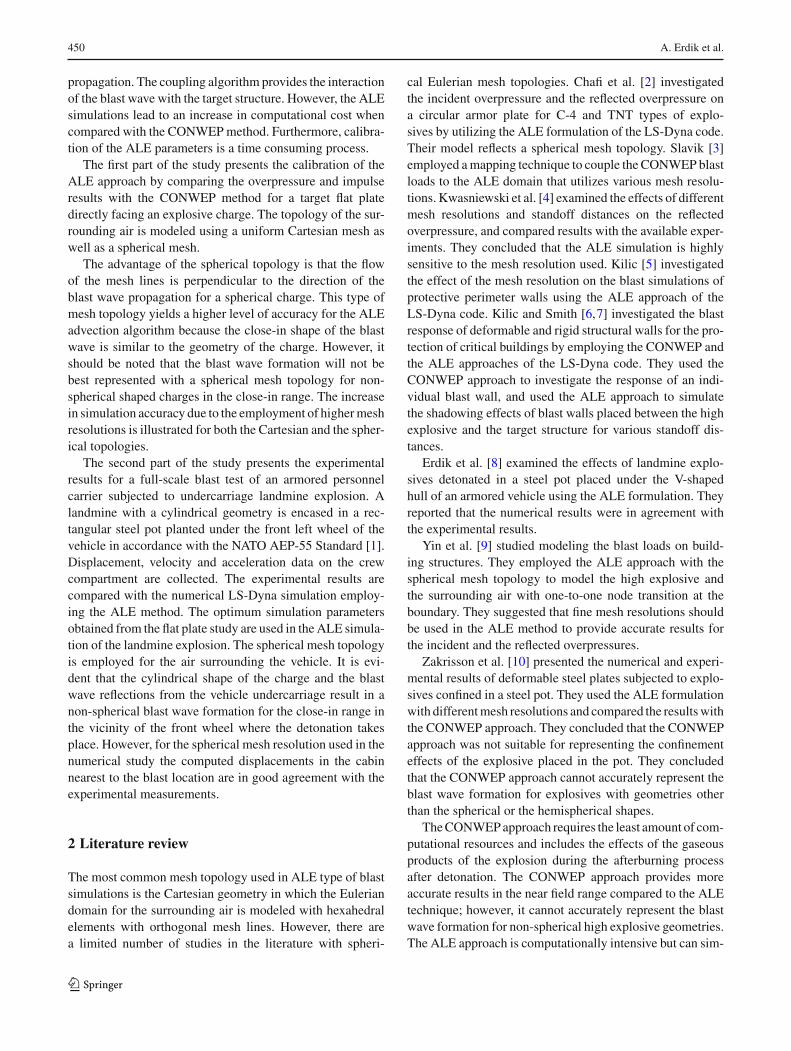
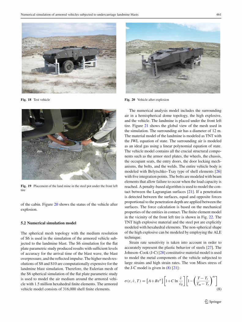
Afull-scale experimentwas conducted by theOtokarOtomo-tiv ve Savunma Sanayi A.S. Corporation in Turkey in 2010.The first author participated in the experiment as an observer.The purpose of the experiment was to assess the response of aMine Resistant and Ambush Protected (MRAP) vehicle sub-jected to landmine blast. Figure 18 shows the experimentalsetup. The NATO AEP-55 Standard Vol-II [1] describes thetest conditions in determining the protection level of logis-tic and light armored vehicles subject to grenade and blastmine threats defined by the NATO Standardization Agree-ment 4569. TNT is selected as the high explosive material.The landmine was placed in a steel pot buried in the groundbeneath the front left tire as illustrated in Fig. 19. The steelpot has a square footprint of 700 mm by 700 mm, and is350 mm in height. The material used for the steel pot isCrMo4. The disc-shaped TNT charge was inserted into thecircular hole in the center of the steel pot. The clearancebetween the TNT charge and the steel pot is 50 mm on thesides aswell as the bottom. The TNT charge is placed into thehole such that it is suspended with the given clearance dis-tances per the NATO AEP-55 Standard [1]. The TNT chargehas a diameter to height ratio of 3:1. The purpose of theplacement of the high explosive in the steel pot is to maxi-mize reflections as set forth by the provisions of the NATOAEP-55 Standard [1].
5.1 Experimental setup
The primary interest of the experiment is to measure the dis-placements around the footrest plate and the sidewall plates ofthe vehicle. Displacements are measured using strain insen-sitive and crushable lead tubes attached on the metal plates
123
Numerical simulation of armored vehicles subjected to undercarriage landmine blasts 461
Fig. 18 Test vehicle
Fig. 19 Placement of the land mine in the steel pot under the front lefttire
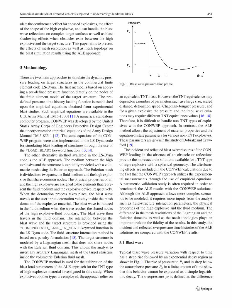
of the cabin. Figure 20 shows the status of the vehicle afterexplosion.
5.2 Numerical simulation model
The spherical mesh topology with the medium resolutionof S6 is used in the simulation of the armored vehicle sub-jected to the landmine blast. The S6 simulation for the flatplate parametric study produced results with sufficient levelsof accuracy for the arrival time of the blast wave, the blastoverpressure, and the reflected impulse. The highermesh res-olutions of S8 and S10 are computationally expensive for thelandmine blast simulation. Therefore, the Eulerian mesh ofthe S6 spherical simulation of the flat plate parametric studyis used to model the air medium around the armored vehi-cle with 1.5 million hexahedral finite elements. The armoredvehicle model consists of 316,000 shell finite elements.
Fig. 20 Vehicle after explosion
The numerical analysis model includes the surroundingair in a hemispherical dome topology, the high explosive,and the vehicle. The landmine is placed under the front lefttire. Figure 21 shows the global view of the mesh used inthe simulation. The surrounding air has a diameter of 12 m.The material model of the landmine is modeled as TNT withthe JWL equation of state. The surrounding air is modeledas an ideal gas using a linear polynomial equation of state.The vehicle model contains all the crucial structural compo-nents such as the armor steel plates, the wheels, the chassis,the occupant seats, the entry doors, the door locking mech-anisms, the bolts, and the welds. The entire vehicle body ismodeled with Belytschko–Tsay type of shell elements [26]with five integration points. The bolts aremodeledwith beamelements that allow failure to occur when the load capacity isreached. A penalty-based algorithm is used tomodel the con-tact between the Lagrangian surfaces [21]. If a penetrationis detected between the surfaces, equal and opposite forcesproportional to the penetration depth are applied between thesurfaces. The force calculation is based on the mechanicalproperties of the entities in contact. The finite element modelin the vicinity of the front left tire is shown in Fig. 22. TheTNT high explosive material and the steel pot are explicitlymodeled with hexahedral elements. The non-spherical shapeof the high explosive can be modeled by employing the ALEtechnique.
Strain rate sensitivity is taken into account in order toaccurately represent the plastic behavior of steels [27]. TheJohnson–Cook (J-C) [28] constitutive material model is usedto model the metal components of the vehicle subjected tolarge strains and high strain rates. The von Mises stress ofthe J-C model is given in (8) [21]:
σ(ε, ε̇, T ) = [A+Bεn
] [1+C ln
ε̇
ε̇0
] [1−
(T− TrTm− Tr
)m]
(8)
123
462 A. Erdik et al.
Fig. 21 Illustration of the numerical model involving the vehicle, thesurrounding air, and the high explosive
Fig. 22 Finite element mesh of the high explosive and the steel potcontainment under the front left tire
where ε is the equivalent strain, ε̇ε̇0
is the dimensionless plas-tic strain rate, Tr is the room temperature, and Tm is themelting temperature. A, B,C , n, andm are the material para-meters. The vehicle body is covered with the Armox500Ttype of armor steel and the J-C material model parametersare obtained from the technical report FOI–R–1068–SE [29].
5.3 Comparison between the experimental resultsand the simulation results
Figure 23 demonstrates the behavior of the vehicle and thepropagation of the blast waves during the 40, 200, 5500,and 7000 microseconds of the landmine blast simulation insequence.
Figure 23a shows the detonated landmine and the resultingshock wave progressing in a hemispherical volume. Fig-ure 23b illustrates the advance of the shock wave while itis beginning to engulf the front tire. The shock wave is re-directed because of the obstruction caused by the frontwheel.Figure 23c shows the flow of the blast wave between thetwo front tires. The coupling algorithm is able to capture thecomplex 3D flow phenomenon that occurs during the blastprocess. The blast wave progression in the Eulerian domainsuccessfully interacts with the Lagrangian elements of the
vehicle body. Figure 23d illustrates the blast waves engulf-ing the entire vehicle body. The regions outlined in red colorillustrate the higher concentrations of the reflected overpres-sures.
Figure 24a provides the sensor locations inside the vehi-cle body. Figure 24b demonstrates the comparison of theexperimentallymeasured displacements and the results of thenumerical simulation. Sensor #8 yields the largest displace-ment and is reported in Fig. 24b with a normalized valueof 100. Displacements at the other sensor locations are pro-vided as a fraction of the normalized value at sensor #8. Inthe post-test evaluation of the vehicle compartment, it wasobserved that the coupling links of the displacement sensorsat locations #1 and #10 slipped during the landmine blast.
Figure 24c shows the deviation percentages of the simu-lation results with respect to the experimental measurementsfor each displacement sensor. The largest discrepanciesoccurred at the sensor locations #1 and #10. The deviationin the blast simulation is less than 25 % for all other sen-sor locations. It was observed after the experiment that themeasurement tubes for monitoring the displacements sepa-rated from the sidewall during the blast process at the sensorlocations #1 and #10. This fact may have caused an impactof the measurement tubes with the sidewalls of the vehicle,resulting in inaccurate measurements of the displacements.The LS-Dyna simulation does not include the afterburningeffects in terms of the gaseous products of the detonationreacting with the ambient oxygen in the surrounding airmedium. As a consequence the release of the afterburningenergy is not modeled in the TNT type of high explosivelandmine simulation. However, the displacements calculatedin the LS-Dyna simulationmatchedwell with the experimen-tal measurements. The simulation run-time on the WindowsHPC Server 2008 computing cluster utilizing 36 processorsis 42,240 seconds.
6 Conclusions
Mesh topology and resolution significantly affect the resultsof a blast simulation. The use of a coarse mesh resolutionyields inaccurate results in the computational fluid dynamicscalculations of the blast wave in the Eulerian domain. Whenthe vehicle body is discretized using a fine mesh resolution,the shell finite elements of the Lagrangian domain governthe critical time step of the explicit time integration andsignificantly increase the computational expense. Therefore,a combination of fine Eulerian mesh resolution and coarseLagrangian mesh resolution is optimal for the ALE model-ing approach used in blast simulations. The main goal of theALE model is to obtain accurate solutions for the reflectedoverpressure and impulse.
123
Numerical simulation of armored vehicles subjected to undercarriage landmine blasts 463
Fig. 23 Illustration of theprogress of the blast wave atvarious instances of thenumerical simulation
Fig. 24 a Sensor locations inside the vehicle cabin (top view), b normalized displacement values, c deviation of the simulation results with respectto the experimental measurements
The Cartesian topology is commonly used in the Euleriandomain of blast simulations. The spherical topology providesan alternative solution and may provide better results for thereflected overpressure and impulse.
A parametric study of a rigid reflecting surface subjectedto a point charge is investigated in this study in order todetermine the effects of mesh resolution and topology forthe incident overpressure, the incident impulse, the reflectedoverpressure, and the reflected impulse. The results are
compared with the experimentally verified CONWEP cal-culations. The Cartesian topology underestimates both thereflected overpressure and impulse even when higher meshresolutions are used.However, the use of a spherical topologyleads to sufficient accuracy in terms of the reflected overpres-sure and impulse. The shock wave arrival time is also betterestimated in the simulations using the spherical topology.
An experimental study was conducted on an armored per-sonnel carrier in 2010.A landminewas placed under the front
123
464 A. Erdik et al.
left tire. The results of the experiment are compared with theblast simulation presented in this study. The rigid reflect-ing surface parametric study shows that accurate results canbe obtained for the S6 spherical topology simulation with alevel of medium-to-higher mesh resolution. Therefore, theLagrangian and Eulerian domains of the armored personnelcarrier are meshed with a spherical mesh topology similar tothe S6 case of the rigid reflecting surface parametric study.The comparison of the experimentally measured displace-ments at various locations around the region of interest showsgood agreement with the ALE blast simulation results.
Acknowledgments The authors would like to thank the Technol-ogy and Innovation Funding Programs Directorate (TEYDEB) ofTUBITAK (Turkish Scientific and Technological Research Council)for the major financial support of the research project provided throughgrant no. 3060493, and the OTOKAR Otomotiv ve Savunma SanayiA.S. Corporation. The second author gratefully acknowledges the fund-ing support provided by TUBITAK through Grant No. 107M002.
Open Access This article is distributed under the terms of the CreativeCommons Attribution 4.0 International License (http://creativecommons.org/licenses/by/4.0/), which permits unrestricted use, distribution,and reproduction in any medium, provided you give appropriate creditto the original author(s) and the source, provide a link to the CreativeCommons license, and indicate if changes were made.
References
1. N.A.T.O.: Procedures for evaluating the protection level of logisticand light armoured vehicles-Mine Threat, 1st edn. Report AEP-55,vol. 2. Allied Engineering Publication (2006)
2. Chafi, M.S., Karami, G., Ziejewski, M.: Numerical analysis ofblast-induced wave propagation using FSI and ALEmulti-materialformulations. Int. J. Impact Eng. 36(10–11), 1269–1275 (2009)
3. Slavik, T.P.: A coupling of empirical explosive blast loads to ALEair domains inLS-DYNA. In: 7thEuropeanLS-DYNAConference,Salzburg, pp. 1–10 (2009)
4. Kwasniewski, L., Balcerzak, M., Wojciechowski, J.: A feasibilitystudy on modeling blast loading using ALE formulation. In: CostAction C26: Urban habitat constructions under catastrophic events,Naples, pp. 127–132 (2010)
5. Kilic, S.A.: ALE mesh sensitivity simulations for blast perimeterwalls in protective structural engineering. In: CMM-2011: 19thInternational Conference on Computer Methods in Mechanics,Warsaw University of Technology, Poland, pp. 243–244 (2011)
6. Kilic, S.A., Smith, P.D.: Behaviour of deformable blast walls forprotective structural design. In: COST Action C-26: Urban habi-tat constructions under catastrophic events, Naples, pp. 477–480(2010)
8. Erdik, A., Kilic, N., Guden, M., Tasdemirci, A.: Numericalapproach to design process of armored vehicles. In: Proceedingsof the ASME: 10th Biennial Conference on Engineering SystemsDesign and Analysis, Istanbul, vol. 4, pp. 231–237, (2010)
9. Yin, X., Gu, X., Lin, F., Kuang, X.: Numerical analysis of blastloads inside buildings. In: Proceedings of the International Sym-posium on Computational Structural Engineering, Shanghai, pp.681–690 (2009)
10. Zakrisson, B., Wikman, B., Haggblad, H.A.: Numerical simula-tions of blast loads and structural deformation from near-fieldexplosions in air. Int. J. Impact Eng. 38(7), 597–612 (2011)
11. Departments of the Army, the Navy, and the Air Force, Struc-tures to resist the effects of accidental explosions. Report TM5-1300/NAVFAC P-397/AFR 88–22, Washington, DC (1990)
12. Hyde, D.W.: User’s guide for microcomputer programs CONWEPand FUNPRO, applications of TM 5–855-1, ’Fundamentals of pro-tective design for conventional weapons’. Report SL-88-1, U.S.Army Corps of Engineers Waterways Experiment Station, Vicks-burg, MS (1988)
13. Kingery,C., Bulmash,G.:Air-blast parameters fromTNTsphericalair burst and hemispherical surface burst. Report ARBRL-TR-02555, Ballistic Research Laboratory, Aberdeen Proving Ground,Aberdeen, MD (1984)
16. Formby, S.A.,Wharton, R.K.: Blast characteristics and TNT equiv-alence values for some commercial explosives detonated at groundlevel. J. Hazard. Mater. 50, 183–198 (1996)
17. Wharton, R.K., Formby, S.A., Merrifield, R.: Airblast TNT equiv-alence for a range of commercial blasting explosives. J. Hazard.Mater. A79, 31–39 (2000)
18. Alonso, F.D., Ferradas, E.G., Perez, J.F.S., Aznar, A.M., Gimeno,J.R., Alonso, J.M.: Characteristic overpressure-impulse-distancecurves for the detonation of explosives, pyrotechnics or unstablesubstances. J. Loss Prevent. Proc. 19, 724–728 (2006)
19. Dobratz, B.M., Crawford, P.C.: LLNL explosives handbook: Prop-erties of chemical explosives and explosive simulants. ReportUCRL-52997, Lawrence Livermore National Laboratory, Califor-nia (1981)
20. Kinney, G., Graham, K.: Explosive shocks in air, vol. 1. Springer,New York (1985)
22. Neuscamman, S., Pezzola, G., Alves, S., Glenn, L., Glascoe, L.:Incorporating afterburn effects into a fast-running tool for model-ing explosives in tunnels. Report UCRL-CONF-599056, LawrenceLivermore National Laboratory, California (2012)
23. Balakrishnan, K., Genin, F., Nance, D.V., Menon, S.: Numeri-cal study of blast characteristics from detonation of homogeneousexplosives. Shock Waves 20, 147–162 (2010)
24. Togashi, F., Baum, J.D., Mestreau, E., Löhner, R., Sunshine, D.:Numerical simulation of long-duration blast wave evolution in con-fined facilities. Shock Waves 20, 409–424 (2010)
25. Zukas, J.A., Walters, W.P.: Explosive effects and applications.Springer, New York (2003)
27. Jones, N.: Structural Impact. Cambridge University Press, GreatBritain (1989)
28. Johnson, G.R., Cook, W.H.: A constitutive model and data formetals subjected to large strains, high strain rates and high tem-peratures. In: Seventh International Symposium on Ballistics, TheHague, The Netherlands, pp. 541–547 (1983)
29. Nilsson, M.: Constitutive model for Armox 500T and Armox 600Tat low and medium strain rates. Report FOI-R-1068-SE, SwedishDefence Research Agency (2003)