Send Orders for Reprints to [email protected]440 The Open Petroleum Engineering Journal, 2015, 8, 440-450 1874-8341/15 2015 Bentham Open Open Access Numerical Simulation of Fracture Permeability Change in Production of Pressure-sensitive Reservoirs with In-situ Stress Field Shaohua Gu 1,* , Yunqing Shi 1 and Zhangxin Chen 2 1 Petroleum Exploration and Production Research Institute of Sinopec, Beijing 100083, China; 2 Department of Chemical and Petroleum Engineering, University of Calgary, Calgary, Alberta, T2N 1N4, Canada Abstract: In pressure sensitive reservoirs, interaction effects among the porous media flow field, the fracture field and the stress field can cause some specific flow characteristics entirely different from those in conventional reservoirs. Dynamic fracture behavior is one of them, which generates a change in the value of fracture aperture and even a variation in the anisotropy of permeability. In this paper, we focus on the dynamic behavior of fractures and some affecting factors, in- cluding driving pressure and in-situ stress. Numerical discrete fracture network (DFN) models are built and solved by the finite element method to investigate what the range-ability the fracture presents and what impact these affecting factors have. In these mathematical models, both dynamic fractures and the fluid-solid coupling are taken into account, and a stress-strain model, a flow field model and a fluid-solid coupling model are included. Based on the models, the variation of fracture aperture in pressure sensitive reservoirs is studied and the results show that a different direction and connectivity of fractures lead fracture dilation to varying degrees as pressure changes so that the idea of anisotropic frac- ture porosity is proposed for reservoir scale simulation. The study also indicates that the drop of formation pressure de- termines the conductivity of fractures and anisotropy of permeability but just has a slight impact on the direction of prin- cipal permeability. Finally, the study shows the interaction of the in-situ stress pressure and the fracture field. Keywords: Anisotropy, DFN model, fractured reservoir, in-situ stress, pressure sensitive. 1. INTRODUCTION Low permeable oil reservoirs represent more than 50% of newly discovered oil reservoirs around the globe, and a con- siderable number of them contain fractures. In this type of reservoirs, matrix blocks are tight and poorly permeable so they can only function as reservoir space. The fractures can serve as channels or baffles for fluids to flow, which is cru- cial for efficient and rational development of these reser- voirs. This type of reservoirs always presents two features: The first one is anisotropic permeability, especially common in fractured reservoirs. These reservoirs have been found in abundance, including the Spraberry Frend oil reservoir in Texas [1] and the Lisburne reservoir in Alaska [2], and the Jingan oil reservoirs [3] in Ordos Basin. In particular, China is a good representative in possessing anisotropic oil reser- voirs. The main difficulty in such reservoirs is gathering in- situ fracture attributes from limited information and assess- ing what the permeability is in these reservoirs [4]. The study in this area has been performed by many researchers in recent years. Guo et al. [5] proposed a method for estimating directional fracture permeability from pressure data recorded during single well tests. Khamis et al. [6] and Chen et al. [7] both used interference and pulse well testing to analyze ani- sotropic permeability in full tensor. Liu et al. [8] proposed a *Address correspondence to this author at the Petroleum Exploration and Production Research Institute of Sinopec, Beijing 100083, China; Tel: +86 010 82312121; Fax: 010-82312751; E-mail: [email protected]comprehensive method to measure the anisotropic perme- ability of a core sample from formation. Graziano et al. [9] used a combination of image logs, WFTs and Mini DSTs for integrated formation evaluation in an anisotropic reservoir located in Indonesia. Kadet et al. [10] proposed a laboratory method for anisotropic reservoir properties determination. The other feature is a fluid-solid coupling effect in pres- sure sensitive formation. This feature brings more challenges to reservoir engineers, and some researchers have also con- tributed in this area. Wang et al. [11] using an experimental method found that reservoir pore pressure fluctuates to some extent during a CO 2 flood, causing a change in effective con- fining pressure. The result is rock deformation and a reduc- tion in permeability (particularly, with a reduction in fracture permeability), causing increased flow resistance in the frac- ture space. Dunayevsky et al. [12] used a numerical method to investigate the effect of water flooding to a stress field. Other researchers showed that fracture aperture and fracture permeability are not only related to flow pressure [13, 14] but also are influenced by the in-situ stress field [15-17], even by temperature in non-isothermal reservoirs [18]. From the above analysis, a low permeable fractured res- ervoir is a complex system affected by flow in porous media, fracture shape and distribution, in situ stress field, and even a production approach, such as injection pressure and thermal production. To solve this multi-physics field coupled prob- lem, it is necessary to include as many factors as possible. Only in this way can research be consistent essentially with the reservoir prototype in nature. Even faced with lots of hardship, researchers have made some progress. Min et al.
Low permeable oil reservoirs represent more than 50% of newly discovered oil reservoirs around the globe, and a con-siderable number of them contain fractures. In this type of reservoirs, matrix blocks are tight and poorly permeable so they can only function as reservoir space. The fractures can serve as channels or baffles for fluids to flow, which is cru-cial for efficient and rational development of these reser-voirs.
This type of reservoirs always presents two features: The first one is anisotropic permeability, especially common in fractured reservoirs. These reservoirs have been found in abundance, including the Spraberry Frend oil reservoir in Texas [1] and the Lisburne reservoir in Alaska [2], and the Jingan oil reservoirs [3] in Ordos Basin. In particular, China is a good representative in possessing anisotropic oil reser-voirs. The main difficulty in such reservoirs is gathering in-situ fracture attributes from limited information and assess-ing what the permeability is in these reservoirs [4]. The study in this area has been performed by many researchers in recent years. Guo et al. [5] proposed a method for estimating directional fracture permeability from pressure data recorded during single well tests. Khamis et al. [6] and Chen et al. [7] both used interference and pulse well testing to analyze ani-sotropic permeability in full tensor. Liu et al. [8] proposed a
*Address correspondence to this author at the Petroleum Exploration and
Production Research Institute of Sinopec, Beijing 100083, China;
comprehensive method to measure the anisotropic perme-ability of a core sample from formation. Graziano et al. [9] used a combination of image logs, WFTs and Mini DSTs for integrated formation evaluation in an anisotropic reservoir located in Indonesia. Kadet et al. [10] proposed a laboratory method for anisotropic reservoir properties determination.
The other feature is a fluid-solid coupling effect in pres-sure sensitive formation. This feature brings more challenges to reservoir engineers, and some researchers have also con-tributed in this area. Wang et al. [11] using an experimental method found that reservoir pore pressure fluctuates to some extent during a CO2 flood, causing a change in effective con-fining pressure. The result is rock deformation and a reduc-tion in permeability (particularly, with a reduction in fracture permeability), causing increased flow resistance in the frac-ture space. Dunayevsky et al. [12] used a numerical method to investigate the effect of water flooding to a stress field. Other researchers showed that fracture aperture and fracture permeability are not only related to flow pressure [13, 14] but also are influenced by the in-situ stress field [15-17], even by temperature in non-isothermal reservoirs [18].
From the above analysis, a low permeable fractured res-ervoir is a complex system affected by flow in porous media, fracture shape and distribution, in situ stress field, and even a production approach, such as injection pressure and thermal production. To solve this multi-physics field coupled prob-lem, it is necessary to include as many factors as possible. Only in this way can research be consistent essentially with the reservoir prototype in nature. Even faced with lots of hardship, researchers have made some progress. Min et al.
Numerical Simulation of Fracture Permeability Change in Production The Open Petroleum Engineering Journal, 2015, Volume 8 441
[19] used a numerical method to study the stress-dependent permeability of fractured rock in consideration of stress fields and fracture networks. Wong et al. [20, 21] used a simulator to investigate the behavior of dynamic permeabil-ity in reservoirs.
In this paper, we focus on understanding the impact of far-field stress and injection pressure on the dynamic anisot-ropic permeability behavior. In order to investigate this prob-lem, we build numerical DFN (discrete fracture network) models by using the finite element method to solve multi-physics coupled problems and simulate the behavior of dy-namic anisotropic permeability in anisotropic fractured res-ervoirs. A tensor theory is applied to analyze the results, with some discussions followed.
2. MODELING OF FRACTURE RESERVOIRS
2.1. Solid Modeling
Here we have a 2D plane model. Displacement of the solid matrix is designated by the components ux, uy. The stress component in each direction satisfies
xx+
yx+ f
x= 0
yy+
xy+ f
y= 0
(1)
According to constitutive equation, the normal strain is
xx=
xx
E E yy
yy=
xx
E E yy
xy= G
xy
(2)
In the above model, the shear modulus is
G =E
2 1+ v( ) (3)
With no respect to body force, the constitutive equation set can be written as
xx
yy
xy
=1
1 2
E 0E 0
0 0 2G(1- 2 )
xx
yy
xy
(4)
According to geometric equation, the normal strain rela-tionship function is
xx=uxx
x
yy=
uyy
y
(5)
According to geometric equation, the shear displacement function is
xy=
1
2xx+
yy( ) (6)
Navier-Stokes equation in porous media is
= (l+
s(1 ))g (7)
According to the Biot’s theory [22], then we have a 2D
stress field model from the above equations
G2uxx+G
1
xy
x B
p
x= 0
G2uyy+G
1
xy
y B
p
y= 0
(8)
2.2. Fluid Flow Modeling
In matrix, the fluid equation from conservation of mass is
t(
l m) + (
lu
m) = Q
m (9)
In fractures, it is
d
f t(
l f) + (
lu
fd
f) = Q
fd
f (10)
The velocity from Darcy’s law in matrix is
um=
Km
μ( P
l lg D) (11)
In fractures, it is
uf=
Kf
μ( P
l lg D) (12)
Furthermore, the storage model is
t( p
l m) =
fS
m
pf
t (13)
Thus the pressure formulation in matrix is
lS
m
pl
t+
l[
km
μ( p
l+
lg D)] = Q
m (14)
In fractures, it is
lS
fb
f
pl
t+
lq
f= Q
fb
f (15)
2.3. Fluid-solid Coupling Model
From the fluid pressure, the stress-strain equation is
xx
yy
xy
=1
1 2
E 0E 0
0 0 2G(1- 2 )
xx
yy
xy
B
px
py
0
(16)
According to the Biot’s theory [22], the fluid pore pres-
sure is:
p
f=
(B
)
S (17)
In a matrix-fracture system, fractures and matrix have different flow characteristics. The storage coefficient in ma-trix is
442 The Open Petroleum Engineering Journal, 2015, Volume 8 Gu et al.
S
m= C
l m+ C
p(1
m) (18)
But in fractures, according to the data of experiments in [23], we know that a nonlinear relationship exists between permeability and the fluid pressure. Using the concept of a DFN model, fluid is full of the fracture space so the storage coefficient in fractures is
S
f= C
l (19)
The aperture of fractures is [24, 25]
bf=
bo
1+ 9
nref
+ bres
(20)
The effective stress is
=
nP
lf (21)
Finally, the fracture flow is
qf=
bf
μ
1
12
bf
2
i=1
n
P
x (22)
2.4. Initial and Boundary Conditions
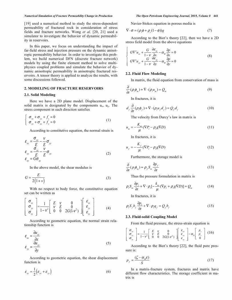
The solution of the governing equations for the above model requires a description of the initial state of the reser-voir and appropriate far-field boundary conditions. The model can be depicted as in Fig. (1).
2.5. Procedure of Computing
The above model of full partial differential equations de-scribing the reservoir behavior is solved using the finite ele-ment method, and the calculation process is described as in
Fig. (2). (1) The flow equation, including the matrix flow and fracture flow, is firstly solved to find the velocity and pressure fields; (2) then the stress-strain equation is solved to obtain the variation of stresses field; (3) new deformation of rock is next updated through solving the fluid-solid coupled model; (4) reservoir properties, including facture aperture and average permeability, can be calculated; (5) the flow model is solved to get the new pressure distribution accord-ing to new fracture permeability; (6) finally, the whole proc-ess of permeability variation can be realized. The parameters used for solution are listed in Table 1, and all values are fixed unless otherwise stated.
3. NUMERICAL INVESTIGATION AND DISCUS-SIONS
3.1. Variation of Fracture Aperture and Porosity
The geometry of the simulated fractures is built up in a model as in Fig. (3). In this model, four numbered fractures form a radicalized pattern with one cross-point and each of them is placed every 45 degrees. The rock with a surrounding rock pressure is drained from the left side to the right side so the variation of fracture permeability can be detected through numerical modeling. The model is calculated five times, and the calculation time is 360 days till the state stage reached. The inlet pressure is set as 12, 14, 16, 18, and 20 MPa, respec-tively. The outlet pressure is 10Mpa and the in-situ stress is 10MPa; other parameters are given in Table 1. After calcula-tion, the pressure distribution is shown in Fig. (4), and the fracture aperture with different directions is displayed in Fig. (5).
From the calculations, the aperture of every fracture in-creases with the pressure rising on the same tendency, and the more the pressure rises, the more the fractures open, which can be seen from Fig. (5). However, the change of average aperture of each fracture is to an apparently varying
Fig. (1). A schematic representation of initial and boundary conditions of dynamic flow in matrix-fracture media.
Numerical Simulation of Fracture Permeability Change in Production The Open Petroleum Engineering Journal, 2015, Volume 8 443
Fig. (2). A schematic representation of the calculation process.
Table 1. Model parameters and corresponding values.
Pa s -- μm2 MPa-1 MPa-1 μm μm μm MPa -- -- MPa Kg m-3 Kg m-3
Fig. (3). A sketch map of (a) fracture distribution and (b) FEM mesh generation.
Fig. (4). A distribution map of pressure fields in (a) 2D and (b) 2D field elevation when the inlet pressure is 20MP and the outlet pressure is
10MP.
444 The Open Petroleum Engineering Journal, 2015, Volume 8 Gu et al.
Fig. (5). Effect of different fracture direction on the extent of fracture aperture vs. pressure difference, (a) fracture 1 (b) fracture 2 (c) fracture
3 and (d) fracture 4.
degree. As for Fracture 1, the aperture of the head end (the end of this fracture close to inlet) opens in the maximum
level, and the tail end (the end of this fracture close to outlet)
presents little difference with the initial condition. The drop of fracture aperture from the head end to the tail end keeps a
near-linear relationship. It is because Fracture 1 links inlet
with outlet directly so its pressure gradient is maximum among all fractures, which can be seen from Fig. (5). Frac-
ture 2 presents the same linear variation trend, but to a lesser
extent. It is because Fracture 2 is not connected to both inlet and outlet. Compared with the matrix, opening fractures
have more conductivity so the pressure consumes more in
matrix from inlet to the head end and from the tail end to outlet than in the fracture, as Fig. (5) shows. Different from
the above two examples, Fracture 3 shows a nonlinear varia-
tion trend; it can be divided into two parts, where the first part from the head end to the cross-point has a relatively
small pressure gradient and the second part from the cross-
point to the tail end has a relatively large pressure gradient. From the analysis of Fracture 1 and Fracture 2, this phe-
nomenon is not hard to understand. The first part has one
side (inlet of Fracture 3) to link with the matrix so the pres-sure consumes less in this fracture but more in matrix. The
second part has one side to link with the connected fracture
network, and the other side link with outlet so the pressure has no matrix to consume and the pressure gradient is natu-
rally larger. Fracture 4 parallels to inlet and outlet and no
pressure gradient exits so the aperture along this fracture increases on the same level as the pressure rises.
Through the above analysis, we know that not just pres-sure can influence the fracture aperture in pressure sensitive formation; the distribution of a fracture plays a significant role in this area as well. Depending on the fractures in pres-sure sensitive formation with a different direction or conduc-tivity, the performance of aperture change can be wholly different. Because of the aperture linear correlation with fracture porosity [26], the direction and conductivity of a fracture is different so the change of fracture porosity is no longer in the same way. The variation of porosity of an ani-sotropic fracture can be investigated from a DFN model. Yet, due to the lack of precise fracture data and huge amount of computation, the DFN model cannot support a wide range of applications for large-scale reservoir simulation; therefore, a fracture network model from seismic interpretation and geo-statistical analysis still needs to be transformed to a dual-pore or dual-perm model for simulation. Some re-searchers used Eq. 23 to establish the relationship between fracture permeability and porosity [27]
Numerical Simulation of Fracture Permeability Change in Production The Open Petroleum Engineering Journal, 2015, Volume 8 445
k
f= C
fμ
f (23)
If we want to use the above model to simulate an anisot-ropic permeability reservoir and take this relationship be-tween the permeability and porosity into consideration, then Eq. 23 can be written in a nine-point scheme of a 2D grid with three sets of fractures (as Fig. 6 shows) as follows:
kfxx
kfxy
kfyx
kfyy
= Cfμ f f
f f
(24)
But if the formation is pressure-sensitive, Eq. 24 with a bulk fracture volume is no longer suitable. Because the pre-vious studies have already illustrated that a different location of a fracture leads to different performance in an anisotropic reservoir. The technically available way is using a stress-porosity coupling method, rather than a stress-aperture cou-pling model, to simulate a pressure-sensitive fractured reser-voir. However, using the bulk fracture porosity for simula-tion cannot characterize this kind of performance. Therefore, it is necessary to introduce a new concept, anisotropic frac-ture porosity, for simulation of this type of reservoirs. The permeability in an anisotropic reservoir is in tensor form, while the fracture porosity in the same reservoir should be in tensor form as well. This means that every fracture in a dif-ferent direction in Fig. (6) has its own porosity so the equa-tion can be written as
kfxx
kfxy
kfyx
kfyy
= Cfμ fxx fxy
fyx fyy
(25)
In recent years, porous media with anisotropic porosity have already become a hot area of research [28-30]. As for the fractured porous media, the fracture porosity plays a more important role in seepage flow compared with matrix porosity, and even sometimes the anisotropy of the matrix porosity can be ignored in highly fractured media, e.g., in a dual-porosity and single-permeability model. Therefore, in a process of simulating a pressure sensitive fractured reservoir, using an anisotropic fracture porosity model would obtain more reliable results.
Fig. (6). A schematic representation of fracture in formation of a
nine-point scheme grid.
3.2. Effect of Production Process
During practical production of a really low permeable reservoir with fractures, some variation of fracture perme-ability can be detected through a well logging analysis, e.g.,
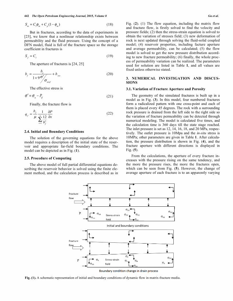
in a geothermal field in Dixie Valley, Nevada, US [31]. It is evident that a production process has an effect on formation productivity so the effect of the development process needs to be discussed. Another model is used here as in Fig. (7).
The model in Fig. (7) is different from the early model: Fracture 4 is deleted so the permeability can be more anisot-ropic. Here we use different inlet and outlet pressures to simulate the two different production methods in a low per-meable reservoir: inlet with 20MPa and outlet with 10MPa (20-10MPa drain) to simulate leading water injection; inlet with 10MPa and outlet with 0MPa (10-0MPa drain) for de-layed water injection. The main distinction of these two methods is the formation pressure difference, which can be realized by adjusting the inlet pressure and outlet pressure of the model. All other parameters are constant, and the calcula-tion results are shown in Fig. (8 and 9).
From the calculation results, we can clearly see that as the field pressure drops, the aperture of fractures decreases simultaneously. In addition, the two obvious distinctions can be detected: one difference between 10-0MPa drain and 20-10MPa drain is that all fractures have a linear pressure varia-tion along the fracture, and the pressure gradient in the frac-tures is nearly the same as that in matrix, as Fig. (8) shows; the other difference is that the aperture of all parts of all frac-tures decreases to a nearly same value in the 10-0MPa drain process, as Fig. (9) shows. The reason is that as the pressure drops fractures closes more with less aperture and lose their conductivity, and permeability of the closed fractures approaches the permeability of matrix so the pressure gradi-ent in both fractures and matrix are nearly the same.
It is also at the point where the anisotropy of permeabil-ity changes as the fracture closes and permeability declines. Here we use the method of fracture permeability in tensor form by Cartesian coordinates [32] to calculate the perme-ability, which is
K =
kfi+ 2k
m
2+
kfi
2cos 2
i
kfi
2sin 2
i
kfi
2sin 2
i
kfi+ 2k
m
2
kfi
2cos 2
i
i=1
N (26)
By ignorance of matrix permeability, Eq. 26 can be writ-ten in short form as follows:
K = kf
cos2
sin cos
s in cos sin2
(27)
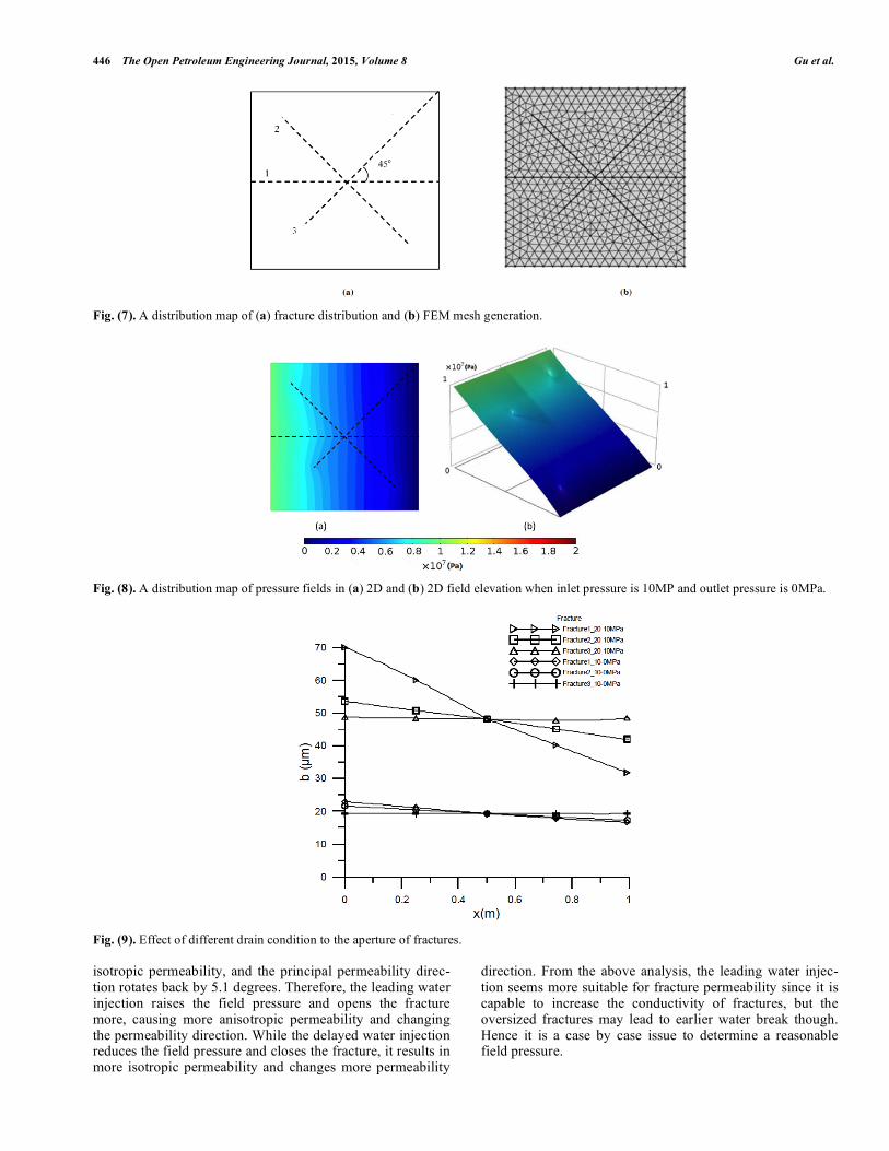
Then the principal permeability value and the principal permeability direction can be calculated, and the calculation results are given in Fig. (10).
Fig. (10) shows that the principal permeability propa-gates some distance in the 20-10MPa drain process and the first principal propagates more compared with other slightly changed ones so the permeability of formation becomes more anisotropic, and the principal permeability directions rotates 8.4 degrees in the clockwise direction. Moreover, the first principal permeability is nearly twice as the secondary principal permeability in the 20-10MPa drain process, and, as a result, the formation presents a strong anisotropy. How-ever, as the field pressure drops, both values of the first and second principal permeability decline to a nearly same value so the anisotropic permeability becomes approximately
446 The Open Petroleum Engineering Journal, 2015, Volume 8 Gu et al.
Fig. (7). A distribution map of (a) fracture distribution and (b) FEM mesh generation.
Fig. (8). A distribution map of pressure fields in (a) 2D and (b) 2D field elevation when inlet pressure is 10MP and outlet pressure is 0MPa.
Fig. (9). Effect of different drain condition to the aperture of fractures.
isotropic permeability, and the principal permeability direc-tion rotates back by 5.1 degrees. Therefore, the leading water injection raises the field pressure and opens the fracture more, causing more anisotropic permeability and changing the permeability direction. While the delayed water injection reduces the field pressure and closes the fracture, it results in more isotropic permeability and changes more permeability
direction. From the above analysis, the leading water injec-tion seems more suitable for fracture permeability since it is capable to increase the conductivity of fractures, but the oversized fractures may lead to earlier water break though. Hence it is a case by case issue to determine a reasonable field pressure.
Numerical Simulation of Fracture Permeability Change in Production The Open Petroleum Engineering Journal, 2015, Volume 8 447
Fig. (10). A diagrammatic drawing of change of principle permeability direction in polar coordinates with different drained condition.
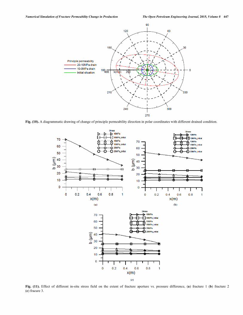
Fig. (11). Effect of different in-situ stress field on the extent of fracture aperture vs. pressure difference, (a) fracture 1 (b) fracture 2
(c) fracure 3.
448 The Open Petroleum Engineering Journal, 2015, Volume 8 Gu et al.
Fig. (12). A diagrammatic drawing of change of principle permeability direction in polar coordinates with different in-situ stress field.
Fig. (13). Principal stress distribution with 10MPa in-situ stress field: (a) no fracture and (b) anisotropic fracture.
3.3. Interaction Effect with in-situ Stress Field
In-situ stress has a major impact on reservoir develop-ment, especially in a pressure sensitive reservoir. If the for-mation is pressure sensitive, the fracture is stress-dependent as well, and what effect the in-situ stress has is necessary to be investigated. Here the model in Fig. (7) is still used, but the in-situ stress is conducted with 10MPa, 15MPa, and 20MPa, while keeping other parameters constant. The calcu-lation results can be seen in Figs. (11 and 12).
As can be seen from Fig. (11), the more the in-situ stress is, the less deformation the fracture performs in the devel-opment process, and the smaller aperture can be detected in all fractures. Different from the above situation, the initial aperture of fractures also declines as the in-situ stress rises. A slight variation in the direction still exists but is hard to be observed as the stress rise; anisotropic permeability remains. It illustrates that the stress has an intensive impact on the value of permeability but little impact on anisotropy and the
principal direction of permeability. Actually, the in-situ stress enhances with depth, and it means if the reservoir is deeper, the aperture of fractures becomes smaller and the reservoir should be more isotropic.
Fluid-solid coupling is an existing phenomenon in porous media flow, and what influence the stress field has for ani-sotropic fractures remains as an open research question. Here we simulate two models, one with the fractures as in Fig. (7) and the other with no fracture. The drain condition is 20-10MPa and in-situ stress 10MPa; no other parameters change. The outcomes from the calculations are represented in Fig. (13), from which we can observe that if a fracture is parallel to the drain pressure gradient, no obvious change can be seen in Fig. (13a). If the fracture and drain pressure gradi-ent are unparalleled, the principal stress in the area among the fractures or near the fractures rotates, and this can be seen from Fig. (13b). It indicates a strong effect by distribu-tion of fractures to the stress field.
Numerical Simulation of Fracture Permeability Change in Production The Open Petroleum Engineering Journal, 2015, Volume 8 449
CONCLUSION
In this paper, a model coupling the porous media flow field and the stress field has been used to study the effect of dynamic behavior of fractures in a production process of oil reservoirs and its influencing factors. Through a series of modeling and simulations, the following conclusions can be summarized:
1. In simulation of pressure-sensitive fractured reservoirs, the coupling of the porous media flow field, fracture field and in-situ stress must be taken into consideration for modeling. Only in this way can the variation of reservoir properties be reflected in detail.
2. Pressure rise can increase the fracture aperture in pres-sure-sensitive formation, and a different direction and connectivity of fractures lead fracture dilation to varying degrees. Based on this finding, the idea of anisotropic fracture porosity is proposed for reservoir-scale simula-tion of pressure-sensitive fractured reservoirs with in-situ stress.
3. In a production process, the level of formation pressure determines the conductivity of fractures and anisotropy of permeability. The lower the formation pressure is, the less the fracture conductivity is and the more isotropic the permeability is. Its slight effect on the direction of principal permeability is also discovered.
4. In-situ stress has an intensive effect on the value of per-meability but a bare effect on anisotropy and the direc-tion of principal permeability. The more the in-situ stress is, i.e., the deeper the formation is, the less the permeabil-ity is. In addition, the fracture field has correlated with the stress field, and its distribution can change the direc-tion of principal stress drastically.
CONFLICT OF INTEREST
The authors confirm that this article content has no con-flict of interest.
ACKNOWLEDGEMENTS
The authors are grateful for financial support from Sci-ence and Technology Project (Grant No. 2011ZX05009) of China and China Scholarship Council. The authors also thank Mr. Junlai Wu for his heuristic physical experiments.
LIST OF SYMBOLS
bf = Fracture aperture (m)
bo = The maximum fracture closure (m)
bres = Residual fracture aperture (m)
Cl = Compressibility of liquid (Pa-1
)
Cp = Compressibility of pore volume (Pa-1
)
D = Depth (m)
E = Young's modulus (Pa)
fi = Body force (N)
G = Shear modulus (Pa)
km = Permeability of matrix (μm2)
kf = Permeability of fracture (μm2)
Pl = Liquid phase pressure (MPa)
Plf = Liquid phase pressure in fractures (MPa)
P0 = Initial pressure (MPa)
qf = Fracture liquid flow (m s-1
)
Qf = Mass source term in fractures (kg m-3
s-1
)
Qm = Mass source term in matrix (kg m-3
s-1
)
S = Storage coefficient (Pa-1
)
Sf = Storage coefficient in fractures (Pa-1
)
Sm = Storage coefficient in matrix (Pa-1
)
t = Time (s)
um = Darcy velocity in matrix (m s1)
uf = Darcy velocity in fractures (m s1)
uxx = Displacement in x direction (m)
uyy = Displacement in y direction (m)
B = Biot-Wilies coefficient (dimensionless)
= Lame’s first constant (Pa)
= Piezo conductivity factor (dimensionless)
= Variation of fluid content (dimensionless)
xx = Normal Stress tensor components in x direction (Pa)
yy = Normal Stress tensor components in y direction (Pa)
xy = Shear stress tensor components (Pa)
xx = Normal Strain in x direction (m)
yy = Normal Strain in y direction (m)
yy = Normal Strain in y direction (m)
xy = Shear Strain (m)
’ = Effective stress (Pa)
nref = Effective normal stress applied to cause a 90% reduction in the compliant aperture (Pa)
n = Rock stress normal to the fracture surface (Pa)
= Poisson's ratio (dimensionless)
μ = Dynamic viscosity (mPa s)
l = Liquid phase density (Kg m3)
s = Solid phase density (Kg m3)
m = Porosity of matrix (dimensionless)
f = Porosity of fractures (dimensionless)
REFERENCES
[1] E.C. Barfield, J.K. Jordan, and W.D. Moore, “An analysis of large scale flooding in the fractured spraberry frend area reservoir,”
Journal of Petroleum Technology, vol. 4, pp. 15-19, 1959.
450 The Open Petroleum Engineering Journal, 2015, Volume 8 Gu et al.
[2] B.H. Currier, “Lisburne reservoir limited-drainage test: a pilot test
case history,” SPE Formation Evaluation, vol. 5, pp. 337-343, 1990.
[3] W. Hu, Z. Song, H. Liu and Y. Ren, “Experimental research on development fracturing technology of changqing ultra-low perme-
ability reservoirs”, In: International Oil and Gas Conference and Exhibition in China, 2000.
[4] J.P. Lathama, J. Xianga, and M. Belaynehb, “Modelling stress-dependent permeability in fractured rock including effects of
propagating and bending fractures”, International Journal of Rock Mechanics and Mining Sciences, vol. 57, pp. 100-112, 2012.
[5] B. Guo, D.S. Schechter, and A. Banik, “Use of Single-Well Test Data for Estimating Permeability Anisotropy of the Naturally Frac-
tured Spraberry Trend Area Reservoirs”, In: SPE Permian Basin Oil and Gas Recovery Conference, Society of Petroleum Engineers,
Midland, Texas. 1998. [6] M.A. Khamis, E. Ozkan, and R. Raghavan, “Interference Testing
with Horizontal Observation Wells”, In: SPE Annual Technical Conference and Exhibition, 2001.
[7] H.Y. Chen, and L.W. Teufel, “Timing and Distance of Well Inter-ference in Anisotropic Reservoirs”, In: SPE Annual Technical Con-
ference and Exhibition, 2002. [8] Y. Liu, F. Guo, B. Tu, and S. Cheng, “Measuring method for ani-
sotropic permeability by non-uniform radial flow in a whole core”, Acta Petrologica Sinica Journal, vol. 26, pp. 66-68, 2005.
[9] G. Capone, M. Alfio, M. Maurizio, M. Mele, and C. Damronsak, “Integrated Formation Evaluation in an Anisotropic Reservoir Off-
shore Deep Water Indonesia Using a Combination of Image Logs, WFTs and Mini DSTs for Pay and Hydrocarbon Definition”, In:
SPE Annual Technical Conference and Exhibition, Society of Pe-troleum Engineers, Florence, Italy, 2010.
[10] V. Kadet, M. Mame and N. Dmitriev, “Complex Laboratory Method of Reservoir Properties Determination for Anisotropic
Layers at the Flowing of Abnormal Oils”, In: SPE Russian Oil and Gas Conference and Exhibition, Society of Petroleum Engineers,
Moscow, Russia, 2010. [11] W. Rui, Y. Xiang, Z. Renbao, R Wang, R Zhao, P Yan, and D
Freeman, “Effect of stress sensitivity on displacement efficiency in CO2 flooding for fractured low permeability reservoirs”. Petroleum
and Science, vol. 6, pp. 277-283, 2009. [12] V.A. Dunayevsky, M.T. Myers, and M.B. Bennett, “The effects of
sequestration/ water floods on exterior stress fields”. American Rock Mechanics Association, 2012.
[13] G.F. Quan, “Experimental study of hydrogen diffusion behaviors in stress fields”, Corrosion, vol. 53, pp. 99-102, 2012.
[14] S.P. Neuman, “Trends, prospects and challenges in quantifying flow and transport through fractured rocks”, Hydrogeology Jour-
nal, vol. 13, pp. 124-47, 2005. [15] J. Feng, J. Dai, Z. Ma, Y. Zhang, Z. Wang, “The theoretical model
between fracture parameters and stress field of low-permeability sandstones”, Acta Petrologica Sinica Journal, vol. 32, pp. 664-671,
2011. [16] O. Meza, V.P. Gandulias, and E.n. Cordova, “Influence of stress
field in the productivity of naturally fractured reservoirs in meta-morphic basement: a case study of the san pedro field, amotape
group”, In: SPE Latin American and Caribbean Petroleum Engi-neering Conference, Society of Petroleum Engineers, Lima, Peru,
2010.
[17] S. Umam, “Assessing horizontal stress direction using seismic and
borehole geometry data: study from balam south field”, In: Interna-tional Petroleum Technology Conference, Doha, Qatar, 2005.
[18] Y. Li, S. Liu, Z. Wang, J. Yuan, and F. Qi, “Analysis of cement sheath coupling effects of temperature and pressure in non-uniform
in-situ stress field”, In: International Oil and Gas Conference and Exhibition in China, Society of Petroleum Engineers, Beijing,
China, 2010. [19] K.B. Min, J. Rutqvist, C.F. Tsang, and L. Jing, “Stress dependent
permeability of fractured rock masses: a numerical study”, Interna-tional Journal of Rock Mechanics and Mining Science, vol. 41, pp.
1191-210, 2004. [20] R.C. Wong, and Y. LI, “A deformation-dependent model for per-
meability changes in oil sand due to shear dilation”, Journal of Ca-nadian Petroleum Technology, vol. 40, pp. 37-44, 2001.
[21] R.C. Wong, and J. Du, “Application of strain-induced permeability model in a coupled geomechanics-reservoir simulator”, Journal of
Canadian Petroleum Technology, vol. 46, pp. 55-61, 2007. [22] M.A. Biot, “Mechanics of deformation and acoustic propagation in
porous media”, Journal of Applied Physics, vol. 33, pp. 1482-1498, 1962.
[23] C. Jiao, S. He, and Q. Xie, “An experimental study on stress-dependent sensitivity of ultra-low permeability sandstone reser-
voirs”, Acta Petrologica Sinica Journal, vol. 32, pp. 489-494, 2011.
[24] T.W. Hicks, R. Wang, R. Zhao, P. Yan, and D. Freeman, “A hydro-thermo-mechanical numerical model for HDR geothermal reservoir
evaluation”, International Journal of Rock Mechanics and Mining Sciences, vol. 33, pp. 499-511, 1996.
[25] J.W. Richards, K. Watanabe, and H. Takahashi, “Progress toward a stochastic rock mechanics model of engineered geothermal sys-
tems”, Journal of Geophysical Research, Solid Earth, vol. 101, pp. 17481-17496, 1996.
[26] J.P. Bloomfield, J.A. Barker, and N. Robinson, “Modeling fracture porosity development using simple growth laws”, Ground Water,
vol. 43, pp. 314-326, 2005. [27] T.D. Racht, “Fundamentals of Fractured Reservoir Engineering”,
Elsevier Science: USA, 1982. [28] B. Zhu, T.W. Hicks, R.J. Pine, J.W. Richards, and S. Xu, “Porosity
and permeability evolution and evaluation in anisotropic porosity multiscale-multiphase-multicomponent structure”, China Science
Bulletin, vol. 57, pp. 320-327, 2012. [29] D. Piazza, C. Galassi, A. Barzegar, and D. Damjanovic, “Dielectric
and piezoelectric properties of PZT ceramics with anisotropic po-rosity”, Journal of Electroceramics, vol. 24. pp. 170-176. 2010.
[30] M.R. Sommer, R.M. Erb, and A.R. Studart, “Injectable materials with magnetically controlled anisotropic porosity”, ACS Applied
Materials & Interfaces, vol. 4, pp. 5086-5091. 2012. [31] C.A. Barton, S.H. Hickman, R. Morin, M.D. Zoback, and D. Be-
noit, “Reservoir-scale fracture permeability in the dixie valley, ne-vada, geothermal field”, In: Proceedings of the: SPE/ISRM Rock
Mechanics in Petroleum Engineering, 1998. [32] Y. Liu, Z. Ding, Y. Qu, and C. Zhao, “The characterization of
fracture orientation and the calculation of anisotropic permeability parameters of reservoirs”, Acta Petrologica Sinica Journal, vol. 32,
pp. 842-846, 2011.
Received: May 12, 2014 Revised: March 29, 2015 Accepted: April 14, 2015
This is an open access article licensed under the terms of the (https://creativecommons.org/licenses/by/4.0/legalcode), which permits unrestricted, non-
commercial use, distribution and reproduction in any medium, provided the work is properly cited.