Numerical simulation of RCS for carrier electronic warfare airplanes Yue Kuizhi a,b , Liu Wenlin a , Li Guanxiong b , Ji Jinzu b, * , Yu Dazhao a a Department of Airborne Vehicle Engineering, Naval Aeronautical and Astronautical University, Yantai 264001, China b School of Aeronautic Science and Engineering, Beihang University, Beijing 100191, China Received 12 April 2014; revised 6 July 2014; accepted 5 December 2014 Available online 21 February 2015 KEYWORDS Carrier aircraft; Configuration design; Electronic warfare; Physical optics method; Stealth Abstract This paper studies the radar cross section (RCS) of carrier electronic warfare airplanes. Under the typical naval operations section, the mathematical model of the radar wave’s pitch angle incidence range analysis is established. Based on the CATIA software, considering dynamic deflec- tions of duck wing leading edge flaps, flaperons, horizontal tail, and rudder, as well as aircraft with air-to-air missile, anti-radiation missile, electronic jamming pod, and other weapons, the 3D models of carrier electronic warfare airplanes Model A and Model B with weapons were established. Based on the physical optics method and the equivalent electromagnetic flow method, by the use of the RCSAnsys software, the characteristics of carrier electronic warfare airplanes’ RCS under steady and dynamic flights were simulated under the UHF, X, and S radar bands. This paper researches the detection probability of aircraft by radars under the condition of electronic warfare, and com- pletes the mathematical statistical analysis of the simulation results. The results show that: The Model A of carrier electronic warfare airplane is better than Model B on stealth performance and on discover probability by radar detection effectively. ª 2015 The Authors. Production and hosting by Elsevier Ltd. on behalf of CSAA & BUAA. This is an open access article under the CC BY-NC-ND license (http://creativecommons.org/licenses/by-nc-nd/4.0/). 1. Introduction Carrier electronic warfare airplane is one of the necessary models on modern aircraft carriers, where carrier electronic warfare airplanes, strike fighters, early warning aircraft, heli- copters, and transport aircraft unite the carrier aircraft wing together. The EA-6B carrier-borne aircraft of the United States is a carrier electronic warfare aircraft on active service on the Nimitz-class aircraft carriers. It was modified and researched on the basis of the A-6 carrier strike aircraft. The EA-18G carrier-borne aircraft is the next generation of carrier electronic warfare airplane in the United States, which was modified and researched on the basis of the F/A-18F carrier strike aircraft. The derivative of the U.S. carrier electronic warfare aircraft is of great reference for the aircraft config- uration of Chinese carrier aircraft wing. The characteristics of the radar cross section (RCS) of car- rier electronic warfare airplanes are not only the performance which aircraft design and manufacturing units are concerned, but also one of the performance indicators that the military * Corresponding author. Tel.: +86 10 82317503. E-mail address: [email protected](J. Ji). Peer review under responsibility of Editorial Committee of CJA. Production and hosting by Elsevier Chinese Journal of Aeronautics, (2015),28(2): 545–555 Chinese Society of Aeronautics and Astronautics & Beihang University Chinese Journal of Aeronautics [email protected]www.sciencedirect.com http://dx.doi.org/10.1016/j.cja.2015.01.004 1000-9361 ª 2015 The Authors. Production and hosting by Elsevier Ltd. on behalf of CSAA & BUAA. This is an open access article under the CC BY-NC-ND license (http://creativecommons.org/licenses/by-nc-nd/4.0/).
Transcript
Chinese Journal of Aeronautics, (2015),28(2): 545–555
Chinese Society of Aeronautics and Astronautics& Beihang University
Peer review under responsibility of Editorial Committee of CJA.
Production and hosting by Elsevier
http://dx.doi.org/10.1016/j.cja.2015.01.0041000-9361 ª 2015 The Authors. Production and hosting by Elsevier Ltd. on behalf of CSAA & BUAA.This is an open access article under the CC BY-NC-ND license (http://creativecommons.org/licenses/by-nc-nd/4.0/).
Yue Kuizhi a,b, Liu Wenlin a, Li Guanxiong b, Ji Jinzu b,*, Yu Dazhao a
a Department of Airborne Vehicle Engineering, Naval Aeronautical and Astronautical University, Yantai 264001, Chinab School of Aeronautic Science and Engineering, Beihang University, Beijing 100191, China
Received 12 April 2014; revised 6 July 2014; accepted 5 December 2014Available online 21 February 2015
KEYWORDS
Carrier aircraft;
Configuration design;
Electronic warfare;
Physical optics method;
Stealth
Abstract This paper studies the radar cross section (RCS) of carrier electronic warfare airplanes.
Under the typical naval operations section, the mathematical model of the radar wave’s pitch angle
incidence range analysis is established. Based on the CATIA software, considering dynamic deflec-
tions of duck wing leading edge flaps, flaperons, horizontal tail, and rudder, as well as aircraft with
air-to-air missile, anti-radiation missile, electronic jamming pod, and other weapons, the 3D models
of carrier electronic warfare airplanes Model A and Model B with weapons were established. Based
on the physical optics method and the equivalent electromagnetic flow method, by the use of the
RCSAnsys software, the characteristics of carrier electronic warfare airplanes’ RCS under steady
and dynamic flights were simulated under the UHF, X, and S radar bands. This paper researches
the detection probability of aircraft by radars under the condition of electronic warfare, and com-
pletes the mathematical statistical analysis of the simulation results. The results show that: The
Model A of carrier electronic warfare airplane is better than Model B on stealth performance
and on discover probability by radar detection effectively.ª 2015 The Authors. Production and hosting by Elsevier Ltd. on behalf of CSAA & BUAA. This is an
open access article under the CC BY-NC-ND license (http://creativecommons.org/licenses/by-nc-nd/4.0/).
1. Introduction
Carrier electronic warfare airplane is one of the necessary
models on modern aircraft carriers, where carrier electronicwarfare airplanes, strike fighters, early warning aircraft, heli-copters, and transport aircraft unite the carrier aircraft wing
together. The EA-6B carrier-borne aircraft of the UnitedStates is a carrier electronic warfare aircraft on active service
on the Nimitz-class aircraft carriers. It was modified andresearched on the basis of the A-6 carrier strike aircraft. TheEA-18G carrier-borne aircraft is the next generation of carrierelectronic warfare airplane in the United States, which was
modified and researched on the basis of the F/A-18F carrierstrike aircraft. The derivative of the U.S. carrier electronicwarfare aircraft is of great reference for the aircraft config-
uration of Chinese carrier aircraft wing.The characteristics of the radar cross section (RCS) of car-
rier electronic warfare airplanes are not only the performance
which aircraft design and manufacturing units are concerned,but also one of the performance indicators that the military
is concerned when used in combat. The military armamentsdepartment puts forward the stealth performance indicatorsof carrier electronic warfare airplanes, expecting to reduce
the aircraft’s RCS characteristics. At the same time, the army’scombat troops analyze the RCS characteristics of carrier elec-tronic warfare airplanes under the conditions of different
pitching angles and azimuth angles based on active service air-craft, expecting to win local wars under high-tech conditionsbased on current equipment. At present, many scholars’
researches of electronic warfare and stealth characteristics ofaircraft are deeper. In the field of electronic warfare, scholarsstudied the gray characteristics of test management of elec-tronic warfare systems,1 analyzed the electronic interference
power assignment method in cooperative air combats of mixedformation,2 discussed the dynamic decision making methodfor cooperation of airborne hard kill/soft kill weapons,3 and
analyzed cooperative generation of phantom radar track usinga team of electronic combat air vehicles based on range gatepull-off.4 In the field of aircraft conceptual design and stealth
design, scholars at home and abroad studied radar stealth,infrared stealth, visible light stealth, and acoustic stealth tech-nologies, as well as the aerodynamic configuration stealth of
the fuselage and the wing, air inlet stealth, surface crackstealth, and other key technologies of the shape-stealth. Theyalso discussed the material stealth technology and summarizedthe avionics/RF system and other solutions of the radar stealth
technology.5 Some other scholars studied the RCS model andalgorithm and other related contents. For example, Li et al.6
studied Gaussian beam on the terahertz radar cross section
of a conducting cylinder distribution. Shi et al.7 studied RCSstatistical characterization using Weibull distribution. Li et al.8
established a comprehensive stealth performance analysis
method and evaluated stealth aircraft based on the RCS char-acteristics of different targets. Wu and Gong9 studied methodsof reducing the RCS of a radar antenna. Chung10 completed
the numerical simulation of RCS of a metal cone and a plasmacovered metal cone. These researches have reference values forthe numerical simulation of a 3D digital model’s RCS. Liuet al.11 three new control factors were proposed to calculate
a multilevel fast multiple algorithm, and the calculation effi-ciency was improved. Huang et al.12 studied recognition ofthe major scattering sources on complex targets based on the
high frequency RCS integrated calculation technique, whichis suitable for solving large complex targets and targets thatneed a lower RCS accuracy. Ledger and Morgan13 established
a reduced-order model. A 3D electromagnetic scatteringnumerical simulation was made in the paper, and it could fore-cast monostatic RCS quickly. Park and Kim14 put forward anangular division algorithm, which accelerated the prediction of
RCS values for large and complex objective models. Althoughexperts and scholars made a lot of contribution in the field ofelectronic warfare and aircraft stealth in the past, there are
shortages of researches in the two fields. Academic papersabout carrier electronic warfare airplanes have not been col-lected. Researches about the influence of an incident wave’s
pitching angle on RCS characteristics are not in place underoperational conditions, and researches of the range of thewave’s pitching angle are not concrete at the time of stealth
design. Researches on RCS characteristics of aircraft and thedetection probability of aircraft under the condition of elec-tronic interference are not thorough.
Based on previous studies, from analyzing the pitchingangle of radar incident wave in the operational profile of a car-rier electronic warfare airplane, this paper established the 3D
computer aided three-dimensional interface application(CATIA) models of carrier electronic warfare airplanes.Based on the physical optics method and the equivalent elec-
tromagnetic flow method, by the use of developedRCSAnsys software, the RCS characteristics of carrier elec-tronic warfare airplanes were analyzed. This paper also
researched the detection probability of aircraft by radars ofdifferent wave bands under the condition of electronic interfer-ence. This paper expected to provide technical supports forRCS characteristics of carrier electronic warfare airplane
research, and to put forward a reference of the strategy toreduce RCS of carrier electronic warfare airplanes.
2. Theoretical basis
The theoretical basis of numerical simulation of a carrier elec-tronic warfare airplane’s RCS characteristics includes the fol-
lowing three aspects: the analysis of the pitching angle ofradar incident wave in the operational profile, the RCS cal-culation method, and the detection probability model in the
condition of electronic warfare.
2.1. Analysis of the pitching angle of radar incident wave in theoperational profile
In modern air and sea battles, a carrier electronic warfare air-plane faces threats of radar and other electronic equipment on
the enemy’s aircraft carriers, destroyers, carrier-based strikefighters, and electronic warfare and early warning airplanes.After analyzing the American 3D defense system of the aircraft
carrier battle group, this paper concluded the schematic dia-gram of the pitching angle of radar incident wave in the opera-tional profile in Fig. 1.
Fig. 1 illustrates that the pitching angle of the enemy’sradar incident wave related to the aircraft under the typicaloperational profile is as follows:
where b is the pitching angle of the incident wave relative tothe aircraft, which is negative when the radar incident wave
is under the aircraft, bf the pitching angle of the shipboardelectronic warfare aircraft relative to the ground, and bf
Numerical simulation of RCS for carrier electronic warfare airplanes 547
negative when the nose is upward, hd the distance between the
aircraft and the sea level, hm the distance between the targetequipment and the sea level, l the distance between the detec-tion radar of the target equipment and the carrier electronic
warfare airplane; Rd the radius of the earth, which is6371 km in general.
Eq. (2) is the constraint condition of Eq. (1). Radar wavecannot illuminate to the aircraft when Eq. (2) is not set up.
In the derivation process of Eq. (1), because the radius ofthe earth is close to infinity compared with the flight heightof the aircraft, the influence of the radius of the earth to the
aircraft pitching angle relative to the incident wave is ignored.
2.2. RCS calculation method
In this paper, the physical optics method and the equivalentelectromagnetic flow method are used to numerically simulate
the RCS characteristics of the carrier electronic warfareairplane.
The equation used by the physical optics method to calcu-
late surface scattering is as follows:ffiffiffiffiffiffiffirpop ¼ �j kffiffiffi
pp
Zs
n � ðer � hiÞ exp½jkr � ði� sÞ�dS ð3Þ
whereffiffiffiffiffiffiffirpop
is the RCS of one surface, j the imaginary unit and
j2 = �1. k ¼ 2p=k the free space wave number, k the radarincident wavelength, n the unit vector of outer normal direc-tion of the surface, er the unit vector of electric field direction
of the receiving antenna, hi the unit vector of magnetic fielddirection of the incident wave, � the dot product, · the crossproduct, r the vector of the local origin to the surface of unit
dS, i the unit vector of incidence direction, s the unit vector
of scattering direction, s ¼ sjsj, s is the scattering direction.
The equation of the equivalent electromagnetic flowmethod is
ffiffiffiffiffiffiffiffiffirecm
p ¼ 1ffiffiffipp
sin hðEi
0 � tÞfs� ðs� tÞ�
� Z0ðHi0 � tÞgs� t
�� e�j2krt �s sinðkl � sÞ
kl � s ð4Þ
where t is the mandatory edge unit vector direction, h the
included angle of incidence directions i and t, Ei0 the strength
of the incident electric field, f and g are the Yoffie Rousseff
diffraction coefficient, Z0 the wave impedance in vacuum, Hi0
the strength of the incident magnetic field, rt the position vec-tor of the middle of the edge; l the vector of the edge.15–19
The superposition equations of the aircraft are as follows:
r ¼Xni¼1ð ffiffiffiffiffiffiffirpop Þ
iþXni¼1ð ffiffiffiffiffiffiffiffiffirecm
p Þi
����������2
ð5Þ
The arithmetic mean value equation of RCS is as follows:
�rbn�N ¼
1
N� nþ 1
XNu¼n
rbu ð6Þ
The unit conversion equation is as follows:
rdBm2 ¼ 10 lg r ð7Þ
where rbu is the RCS value where the incoming wave pitch
angle is b and the azimuth angle is u, �rbn�N the arithmetic mean
value where the incoming wave pitch angle is b and the
azimuth angle is u (u = n�N), r the RCS of the aircraft, �rthe arithmetic mean value of the aircraft’s RCS, rdBm2 the
RCS of the aircraft.
2.3. Detection probability model in the condition of electronic
warfare
The probability of finding a target while the radar issearching is
where PD is the probability of finding a target, X the angularscanning speed, Dha the horizontal beamwidth; fr the repetitionfrequency, Sjk the signal to noise ratio of the individual pulse,
Pt the power of transmitter, G the antenna gain, k the radar
wavelength, E the pulse compression ratio, �r�15
b the arithmetic
mean value of the aircraft when the forward azimuth anglesare �15 and the pitching angle is b, kb Boltzmann’s constant,T0 the standard room temperature, Bn the noise bandwidth, Fn
the noise factor, L the total loss of system, R the distancebetween the enemy radar and the carrier electronic warfare air-plane, Gt the radar transmitting antenna gain, Dfj the receiver
jamming signal bandwidth, Pj the power of jammer, Gj theantenna gain of jammer, vj the polarization loss of the jammingsignal, Dfr the receiver bandwidth.20
After mastering these theories, the RCS characteristics ofthe carrier electronic warfare airplane can be analyzed.
3. Electromagnetic test validation method
This paper studied the RCS characteristics of the carrier elec-tronic warfare airplane. Based on the physical optics method
and the equivalent electromagnetic flow method, this papercompleted the digital simulation of the RCS characteristicsof the aircraft by the use of the RCSAnsys software.RCSAnsys is a kind of software which tests and analyzes char-
acteristics of an aircraft’s RCS. It was developed based on thenumerical analysis of an aircraft’s RCS. Before analyzing anaircraft’s RCS characteristics, the scientificity and accuracy
of the calculation method of RCSAnsys should be tested bythe electromagnetic test.
3.1. Electromagnetic test verification of aircraft RCS numericalsimulation
In this paper, CATIA software is used to create the 3D digitalaircraft models in Fig. 2. Then, the digital aircraft models are
imported to the RCSAnsys software to numerically simulatethe aircraft’s RCS and conclude the curve of the aircraft’sRCS characteristics.
Fig. 2 3D digital models of the aircraft.
Fig. 4 RCS characteristics from numerical simulation and
electromagnetic test.
548 K. Yue et al.
In this paper, a 3D printer is used to create the 3D scaleentity model of the aircraft as shown in Fig. 3(a). Then, the
model is electromagnetically tested in an anechoic chamberas shown in Fig. 3(b). Finally, the aircraft RCS characteristiccurve of the electromagnetic test is obtained after conversion
as shown in Fig. 4.
3.2. Conclusion of electromagnetic test
In this section, based on the physical optics method and the
equivalent electromagnetic flow method, the RCSAnsys soft-ware is used to simulate the RCS characteristics of the 3D digi-tal aircraft model, and after that, compare the result with the
RCS characteristics obtained from the electromagnetic test.The result is shown in Fig. 4. The initial conditions of thenumerical simulation and experiment are: the incident wave
of radar is X band, the radar incident wavelength is 3 cm,the pitching angle of the incident wave is 0�, the polarizationmethod is horizontal, and the azimuth angle of the plane is
0–180�. It is concluded from Fig. 4 that the RCS value fromthe numerical simulation is in line with that from the electro-magnetic test. The conclusion proves that the method is scien-tific and the numerical simulation is accurate. Next, the
software is used to simulate the RCS characteristics of the car-rier electronic warfare airplane.
Fig. 3 Electromagnetic test of aircraft in an anechoic chamber.
4. Aircraft RCS characteristics simulation and analysis
Aircraft RCS characteristics simulation and analysis include
the following 5 steps:
Step 1. 3D digital model establishing of the carrier elec-
Step 3. Aircraft RCS simulation and analysis.Step 4. RCS characteristics analysis of the carrier-borneelectronic warfare aircraft in climb and dive.Step 5. Detection probability of aircraft analysis.
4.1. 3D digital model establishing of the carrier electronicwarfare airplane
In this paper, CATIA software is used to establish the 3D digi-tal model of the carrier electronic warfare airplane. 3D digital
model establishing of the carrier electronic warfare airplaneincludes the following 3 sections: 3D models of the aircraft;3D models of electronic warfare equipment and weapons;
3D models of the electronic warfare airplane.
4.1.1. 3D models of aircraft
In this section, on the background of the EA-18G carrier elec-
tronic warfare airplane in the U.S. and the carrier electronicwarfare airplane derived from the Su-33 carrier-based aircraftin Russia, CATIA software is used to establish the 3D digital
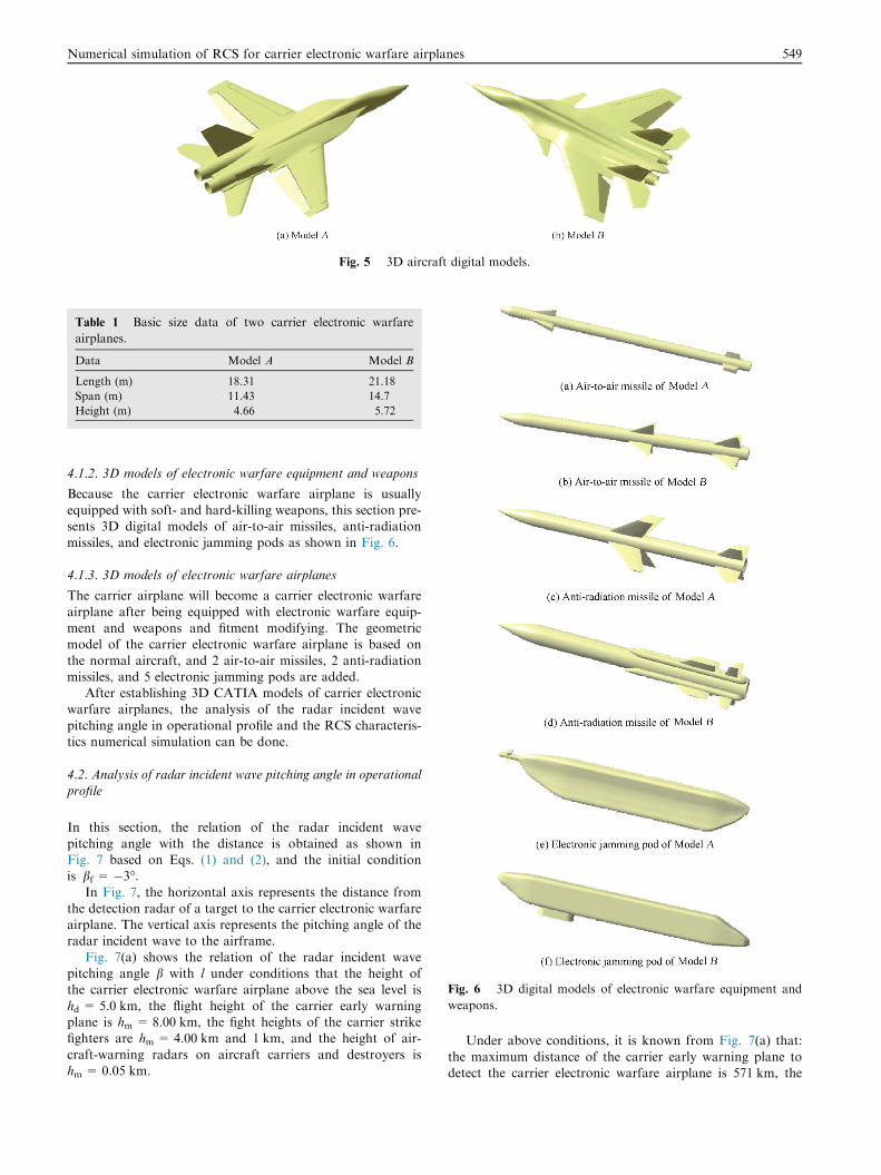
model as shown in Fig. 5. Because EA-18G and Su-33 do notuse stealth-absorbing materials, the RCS characteristics of thetwo aircraft are mainly dependent on the shape of the plane.The 3D models are simplified under the condition that the
main RCS characteristics can be expressed. The basic size dataof two carrier electronic warfare airplanes are in Table 1.
In Fig. 5, Model A carrier electronic warfare airplane is a
kind of normal aerodynamic configuration aircraft with atwo-seater, a twin-engine, twin extraversion vertical tails, a sta-bilator, and a large strake wing. This aircraft has leading edge
flaps and flaperons on wings. Model B carrier electronic war-fare airplane is a kind of tri-surface aerodynamic configurationaircraft with a two-seater, a twin-engine, twin vertical tails, astabilator, and a large strake wing. This aircraft also has lead-
ing edge flaps and flaperons on wings.
Fig. 5 3D aircraft digital models.
Table 1 Basic size data of two carrier electronic warfare
airplanes.
Data Model A Model B
Length (m) 18.31 21.18
Span (m) 11.43 14.7
Height (m) 4.66 5.72
Fig. 6 3D digital models of electronic warfare equipment and
weapons.
Numerical simulation of RCS for carrier electronic warfare airplanes 549
4.1.2. 3D models of electronic warfare equipment and weapons
Because the carrier electronic warfare airplane is usuallyequipped with soft- and hard-killing weapons, this section pre-sents 3D digital models of air-to-air missiles, anti-radiation
missiles, and electronic jamming pods as shown in Fig. 6.
4.1.3. 3D models of electronic warfare airplanes
The carrier airplane will become a carrier electronic warfare
airplane after being equipped with electronic warfare equip-ment and weapons and fitment modifying. The geometricmodel of the carrier electronic warfare airplane is based on
the normal aircraft, and 2 air-to-air missiles, 2 anti-radiationmissiles, and 5 electronic jamming pods are added.
After establishing 3D CATIA models of carrier electronicwarfare airplanes, the analysis of the radar incident wave
pitching angle in operational profile and the RCS characteris-tics numerical simulation can be done.
4.2. Analysis of radar incident wave pitching angle in operationalprofile
In this section, the relation of the radar incident wave
pitching angle with the distance is obtained as shown inFig. 7 based on Eqs. (1) and (2), and the initial conditionis bf = �3�.
In Fig. 7, the horizontal axis represents the distance fromthe detection radar of a target to the carrier electronic warfareairplane. The vertical axis represents the pitching angle of theradar incident wave to the airframe.
Fig. 7(a) shows the relation of the radar incident wavepitching angle b with l under conditions that the height ofthe carrier electronic warfare airplane above the sea level is
hd = 5.0 km, the flight height of the carrier early warningplane is hm = 8.00 km, the fight heights of the carrier strikefighters are hm = 4.00 km and 1 km, and the height of air-
craft-warning radars on aircraft carriers and destroyers ishm = 0.05 km.
Under above conditions, it is known from Fig. 7(a) that:
the maximum distance of the carrier early warning plane todetect the carrier electronic warfare airplane is 571 km, the
radar incident wave pitching angle b is �2.69� at the moment,and b is 3.89� when the detection distance is 25 km; the maxi-
mum distance of the carrier strike fighter to detect the carrierelectronic warfare airplane is 478 km when the height of thecarrier strike fighter is hm = 4.00 km, b is �3.11� at the
moment, and b is �5.29� when the detection distance is25 km; the maximum distance of the carrier strike fighter todetect the carrier electronic warfare airplane is 356 km whenthe height of the carrier strike fighter is hm = 1.00 km, b is
�3.62� at the moment, and b is �12.20� when the detectiondistance is 25 km; the maximum distance of aircraft-warningradars on aircraft carriers and destroyers to detect the carrier
electronic warfare airplane is 277 km, b is �4.02� at themoment, and b is �14.42� when the detection distance is25 km. It can be seen that when the level flight height of the
carrier electronic warfare airplane is 5 km, the incident wavepitching angle of radars outside 25 km and under the heightof 8 km is within the range of �14.42� to 3.89�.
In a similar way, when the carrier electronic warfare air-
plane flies levelly, and the flight height is 0.1 km, Fig. 7(b)shows that the maximum distance of the carrier early warningplane which flies at the height of 8 km to detect the carrier elec-
tronic warfare airplane is 355 km; the maximum distance ofthe carrier strike fighter which flies at the height of 4 km todetect the carrier electronic warfare airplane is 261 km, and
the distance is 148 km when the flight height of the carrierstrike fighter is 1 km; the maximum distance of 0.05 km highaircraft-warning radars on aircraft carriers and destroyers to
detect the carrier electronic warfare airplane is 60 km. Theincident wave pitching angle of radars outside 25 km andunder the height of 8 km is within the range of �3.11� to15.42�.
The following conclusion can be drawn: while designing thestealth plane of which flight height is within the range of0.1 km–5 km, the detection distance of radars outside 25 km
and under the height of 8 km can be reduced if reducing theRCS of the plane of which the pitching angle b is between�14.42� and 15.42�. On the other hand, while performing
the radar detection numerical simulation of planes of whichthe level flight height is within the range of 0.1 km–5.0 km,only the RCS of planes of which the pitching angle b is
between �14.42� and 15.42� need to be analyzed, and thenall the detection distances of radars outside 25 km and underthe height of 8 km can be satisfied.
4.3. Aircraft RCS numerical simulation and analysis
In naval warfare, carrier electronic warfare airplanes mainly
face the detections of UHF band early warning radars on earlywarning planes, X band fire control radars on strike fighters,and S band aircraft-warning radars on aircraft carriers and
destroyers. Under the condition of the same pitching anglesand azimuth angles of the radar incident wave, and underthe detections of UHF, X, S, and other different bands radars,the RCS values of the same carrier electronic warfare airplane
are different.In this section, based on Eqs. (3)–(5), and referring to the
typical radar incident wave pitching angle and radar bands
concluded in Section 4.2, the RCSAnsys software is used tosimulate the RCS of the 3D digital aircraft models built inSection 4.1, and then the intensity distribution of the RCS of
the carrier electronic warfare airplane is obtained as shownin Figs. 8 and 9 under the condition of horizontal polarization,and the RCS characteristics as shown in Fig. 10(a) and (b)
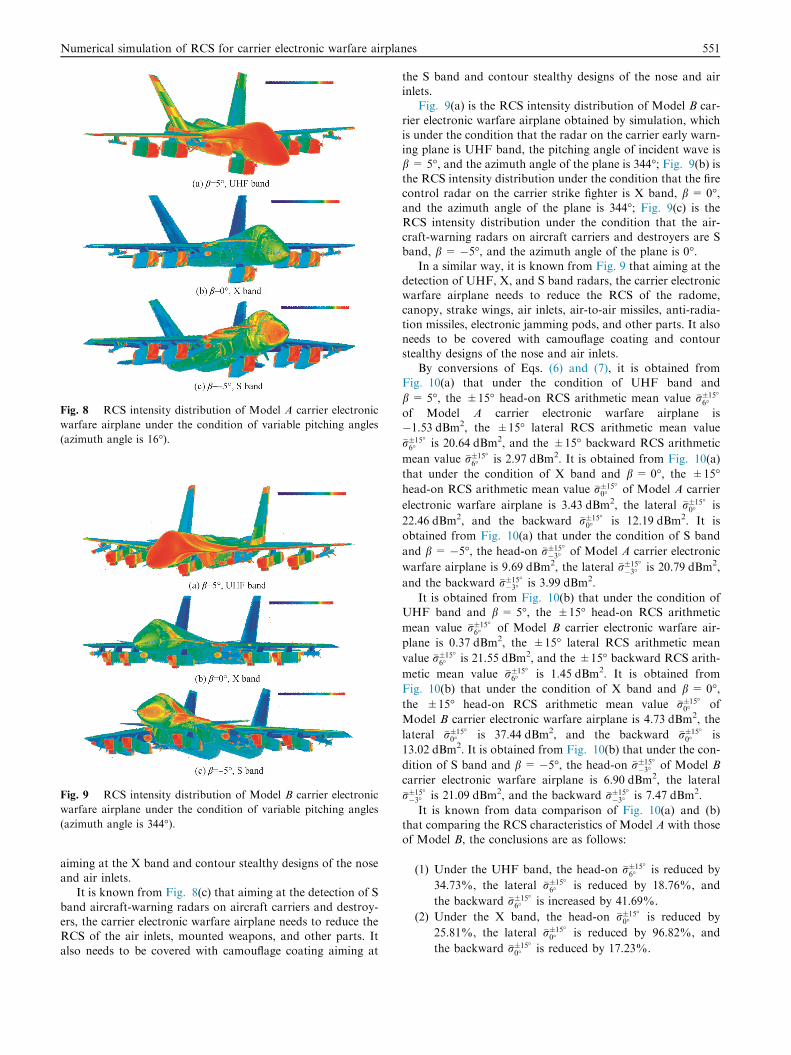
are obtained at the same time.Fig. 8(a) is the RCS intensity distribution of Model A car-
rier electronic warfare airplane obtained by simulation, whichis under the condition that the radar on the carrier early warn-
ing plane is UHF band, the pitching angle of incident wave isb = 5�, and the azimuth angle of the plane is 16�; Fig. 8(b) isthe RCS intensity distribution of Model A under the condition
that the fire control radar on the carrier strike fighter is Xband, b = 0�, and the azimuth angle of the plane is 16�;Fig. 8(c) is the RCS intensity distribution of Model A under
the condition that the aircraft-warning radars on aircraft car-riers and destroyers are S band, b = �5�, and the azimuthangle of the plane is 16�.
It is known from Fig. 8(a) that aiming at the detection ofUHF band radar on the carrier early warning plane, the carrierelectronic warfare airplane needs to reduce the RCS of theradome, canopy, upper surface of the strake wing, and other
parts. It also needs to be covered with camouflage coating aim-ing at the UHF band and contour stealthy design of the nose.
It is known from Fig. 8(b) that aiming at the detection of X
band fire control radar on the carrier strike fighter, the carrierelectronic warfare airplane needs to reduce the RCS of theradome, canopy, strake wings, air inlets, air-to-air missiles,
anti-radiation missiles, electronic jamming pods, and otherparts. It also needs to be covered with camouflage coating
Fig. 8 RCS intensity distribution of Model A carrier electronic
warfare airplane under the condition of variable pitching angles
(azimuth angle is 16�).
Fig. 9 RCS intensity distribution of Model B carrier electronic
warfare airplane under the condition of variable pitching angles
(azimuth angle is 344�).
Numerical simulation of RCS for carrier electronic warfare airplanes 551
aiming at the X band and contour stealthy designs of the noseand air inlets.
It is known from Fig. 8(c) that aiming at the detection of S
band aircraft-warning radars on aircraft carriers and destroy-ers, the carrier electronic warfare airplane needs to reduce theRCS of the air inlets, mounted weapons, and other parts. It
also needs to be covered with camouflage coating aiming at
the S band and contour stealthy designs of the nose and airinlets.
Fig. 9(a) is the RCS intensity distribution of Model B car-
rier electronic warfare airplane obtained by simulation, whichis under the condition that the radar on the carrier early warn-ing plane is UHF band, the pitching angle of incident wave is
b = 5�, and the azimuth angle of the plane is 344�; Fig. 9(b) isthe RCS intensity distribution under the condition that the firecontrol radar on the carrier strike fighter is X band, b = 0�,and the azimuth angle of the plane is 344�; Fig. 9(c) is theRCS intensity distribution under the condition that the air-craft-warning radars on aircraft carriers and destroyers are Sband, b = �5�, and the azimuth angle of the plane is 0�.
In a similar way, it is known from Fig. 9 that aiming at thedetection of UHF, X, and S band radars, the carrier electronicwarfare airplane needs to reduce the RCS of the radome,
canopy, strake wings, air inlets, air-to-air missiles, anti-radia-tion missiles, electronic jamming pods, and other parts. It alsoneeds to be covered with camouflage coating and contour
stealthy designs of the nose and air inlets.By conversions of Eqs. (6) and (7), it is obtained from
Fig. 10(a) that under the condition of UHF band and
b = 5�, the ±15� head-on RCS arithmetic mean value �r�15
6
of Model A carrier electronic warfare airplane is�1.53 dBm2, the ±15� lateral RCS arithmetic mean value
�r�15
6 is 20.64 dBm2, and the ±15� backward RCS arithmetic
mean value �r�15
6 is 2.97 dBm2. It is obtained from Fig. 10(a)
that under the condition of X band and b = 0�, the ±15�head-on RCS arithmetic mean value �r�15
0 of Model A carrier
electronic warfare airplane is 3.43 dBm2, the lateral �r�15
0 is
22.46 dBm2, and the backward �r�15
0 is 12.19 dBm2. It is
obtained from Fig. 10(a) that under the condition of S band
and b = �5�, the head-on �r�15
�3 of Model A carrier electronic
warfare airplane is 9.69 dBm2, the lateral �r�15
�3 is 20.79 dBm2,
and the backward �r�15
�3 is 3.99 dBm2.
It is obtained from Fig. 10(b) that under the condition ofUHF band and b = 5�, the ±15� head-on RCS arithmetic
mean value �r�15
6 of Model B carrier electronic warfare air-
plane is 0.37 dBm2, the ±15� lateral RCS arithmetic mean
value �r�15
6 is 21.55 dBm2, and the ±15� backward RCS arith-
metic mean value �r�15
6 is 1.45 dBm2. It is obtained from
Fig. 10(b) that under the condition of X band and b = 0�,the ±15� head-on RCS arithmetic mean value �r�15
0 of
Model B carrier electronic warfare airplane is 4.73 dBm2, the
lateral �r�15
0 is 37.44 dBm2, and the backward �r�15
0 is
13.02 dBm2. It is obtained from Fig. 10(b) that under the con-
dition of S band and b = �5�, the head-on �r�15
�3 of Model B
carrier electronic warfare airplane is 6.90 dBm2, the lateral
�r�15
�3 is 21.09 dBm2, and the backward �r�15
�3 is 7.47 dBm2.
It is known from data comparison of Fig. 10(a) and (b)that comparing the RCS characteristics of Model A with those
of Model B, the conclusions are as follows:
(1) Under the UHF band, the head-on �r�15
6 is reduced by
34.73%, the lateral �r�15
6 is reduced by 18.76%, and
the backward �r�15
6 is increased by 41.69%.
(2) Under the X band, the head-on �r�15
0 is reduced by
25.81%, the lateral �r�15
0 is reduced by 96.82%, and
the backward �r�15
0 is reduced by 17.23%.
Fig. 10 RCS characteristics of Model A carrier electronic warfare airplane.
552 K. Yue et al.
(3) Under the S band, the head-on �r�15
�3 is increased by
90.41%, the lateral �r�15
�3 is reduced by 6.66%, and the
backward �r�15
�3 is reduced by 55.11%.
The reasons that the RCS of Model A is reduced compared
with that of Model B are as follows:
(1) The size of Model A is smaller than that of Model B.
The length of Model A is reduced by 13.55%, the spanby 22.24%, and the height by 18.53% (The basic sizeis in Table 1).
(2) Model A uses twin extraversion vertical tails while
Model B uses twin vertical tails, so the lateral RCS ofModel A is reduced a lot.
(3) Through simulating the RCS characteristics of the two
3D models, we know the RCS of Model A’s electronicjamming pod is smaller than that of Model B’s.
4.4. RCS characteristics analysis of carrier-borne electronic
warfare aircraft in climb and dive
This paper analyses not only the RCS characteristics of thecarrier-borne electronic warfare aircraft in balanced flight,but also the RCS characteristics in mobile processes, such asclimb and dive. This section analyses the RCS characteristics
of the aircraft during climbing and diving, including threelinks: the establishment of the geometric model, the numericalsimulation of the RCS, and the mathematical statistics analysis
of the RCS.
(1) The establishment of the geometric model
Duck wing, frontal flap, flaperon, horizontal tail, and otherrudder surfaces will be deflected when the carrier-borne elec-
tronic warfare aircraft is in subduction and climb.When climbing, the rudder surface deflection angle of
Model A plane is set as follows: the front flap deflects down5�, the flaperon deflects down 25�, and the horizontal tail
deflects down 25�.When diving, the rudder surface deflection angle of Model
A plane is set as follows: the front flap deflects 0�, the flaperondeflects 0�, and the horizontal tail deflects up 25�.
When climbing, the rudder surface deflection angle of
Model B plane is set as follows: the duck wing deflects up10�, the front flap deflects down 5�, the flaperon deflects down25�, and the horizontal tail deflects down 25�.
When diving, the rudder surface deflection angle of Model
B plane is set as follows: the duck wing deflects down 10�, thefront flap deflects down 0�, the flaperon deflects down 0�, andthe horizontal tail deflects up 25�.
(2) Numerical simulation of airplanes’ RCS
When the incident wave of the radar is X band and hori-zontal polarization, and under the condition that the pitchingangle of the incident wave is �5�, 0�, and 5�, based on thephysical optics method and the equivalent electromagnetic
flow method, the RCS characteristics of Model A and ModelB carrier-borne electronic warfare aircraft in climbing and div-ing have been calculated, as shown in Fig. 11.
(3) RCS contrastive analysis
The mathematical statistics of the RCS characteristics ofthe aircraft in Fig. 11 have been done, and contrastive analysisis shown in Table 2.
It’s known from Fig. 10(a) and (b), and Table 2 that theRCS characteristics in climbing and diving are very differentfrom those in balanced flight. Therefore, this paper suggests:when a plane is approaching enemy targets, before the plane
has been found, the pilot should make the plane in balancedflight and avoid doing big maneuvering flight, in order to avoidenemy radar, for the airplane’s RCS fluctuation is too large.
4.5. Detection probability analysis of carrier electronic warfare
airplane
After obtaining the RCS characteristics curves of the aircraft,this paper anglicized the detection probability of the carrierelectronic warfare airplane under the conditions with and with-
out electronic jamming.The detection probability of the aircraft is obtained by
numerical simulation based on Eqs. (8)–(10) as shown inFig. 12(a) and (b). Initial conditions of numerical simulation
are as follows: the power of transmitter Pt is 10 MW; the
Fig. 11 RCS characteristics of carrier-borne electronic warfare aircraft when climbing and diving.
Table 2 Mathematical statistics of RCS characteristics in climbing and diving.
Mobile process Pitching angle
of incident wave
RCS mean value of Model A in ±30�(dBm2) RCS mean value of Model B in ±30�(dBm2)
Numerical simulation of RCS for carrier electronic warfare airplanes 553
antenna gain G is 100 dB; the pulse compression ratio E is 300;Boltzmann’s constant k is 1.38 · 10�23 WÆs/K; the standard
room temperature T0 is 290 K; the power of jammer Pj is20 kW; the polarization loss of the jamming signal vj is 0.5;the total loss of system L is 20 dB; the noise bandwidth Bn is
0.077 MHz; the noise factor Fn is 55 dB; the horizontalbeamwidth Dha is 7�; the repetition frequency fr is 300 Hz;the angular scanning speed X is 30(�)/s; the antenna gain of
jammer Gj is 7 dB; the receiver bandwidth Dfr is 1.44 MHz;the receiver jamming signal bandwidth Dfj is 1.44 MHz; the
radar transmitting antenna gain Gt is 36 dB; the flight heightsof Model A and Model B are 5 km; the radar wavelengthk = 0.03 m.
When the radar is X band, the RCS of Model A is
�r�15
0 = 3.43 dBm2 = 2.20 m2, and the RCS of Model B is
�r�15
0 = 4.73 dBm2 = 2.97 m2.
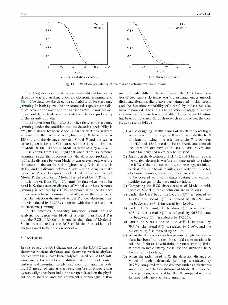
Fig. 12 Detection probability of the carrier electronic warfare airplane.
554 K. Yue et al.
Fig. 12(a) describes the detection probability of the carrier
electronic warfare airplane under no electronic jamming, andFig. 12(b) describes the detection probability under electronicjamming. In both figures, the horizontal axis represents the dis-
tance between the radar and the carrier electronic warfare air-plane, and the vertical axis represents the detection probabilityof the aircraft by radar.
It is known from Fig. 12(a) that when there is no electronicjamming, under the condition that the detection probability is5%, the distance between Model A carrier electronic warfareairplane and the carrier strike fighter using X band radar is
123 km, and the distance between Model B and the carrierstrike fighter is 134 km. Compared with the detection distanceof Model B, the distance of Model A is reduced by 8.20%.
It is known from Fig. 12(b) that when there is electronicjamming, under the condition that the detection probabilityis 5%, the distance between Model A carrier electronic warfare
airplane and the carrier strike fighter using X band radar is48 km, and the distance between Model B and the carrier strikefighter is 56 km. Compared with the detection distance ofModel B, the distance of Model A is reduced by 14.28%.
It is known from Fig. 12(a) and (b) that when the radarband is X, the detection distance of Model A under electronicjamming is reduced by 60.97% compared with the distance
under no electronic jamming. Similarly, when the radar bandis X, the detection distance of Model B under electronic jam-ming is reduced by 58.20% compared with the distance under
no electronic jamming.In the detection probability numerical simulation and
analysis, the reason why Model A is better than Model B is
that the RCS of Model A is smaller than that of Model B.So in order to reduce the RCS of Model B, stealth modi-fications need to be done on Model B.
5. Conclusions
In this paper, the RCS characteristics of the EA-18G carrierelectronic warfare airplanes and electronic warfare airplane
derived from Su-33 have been analyzed. Based on CATIA soft-ware, under the condition of different deflections of controlsurfaces and mounting missiles and electronic jamming pods,
the 3D model of carrier electronic warfare airplanes underdynamic flight has been built in this paper. Based on the physi-cal optics method and the equivalent electromagnetic flow
method, under different bands of radar, the RCS characteris-
tics of two carrier electronic warfare airplanes under smoothflight and dynamic flight have been simulated in this paper,and the detection probability of aircraft by radars has also
been researched. Then, a RCS reduction strategy of carrierelectronic warfare airplanes in stealth subsequent modificationhas been put forward. Through research in this paper, the con-
clusions are as follows:
(1) While designing stealth planes of which the level flightheight is within the range of 0.1–5.0 km, only the RCS
of planes of which the pitching angle b is between�14.42� and 15.42� need to be analyzed, and then allthe detection distances of radars outside 25 km and
under the height of 8 km can be satisfied.(2) Aiming at the detection of UHF, X, and S bands radars,
the carrier electronic warfare airplane needs to reduce
the RCS of the radome, canopy, strake wings, air inlets,vertical tails, air-to-air missiles, anti-radiation missiles,electronic jamming pods, and other parts. It also needsto be covered with camouflage coating and contour
stealthy designs of the nose and air inlets.(3) Comparing the RCS characteristics of Model A with
those of Model B, the conclusions are as follows.
a) Under the UHF band, the head-on �r�15
6 is reduced by
34.73%, the lateral �r�15
6 is reduced by 18.76%, and
the backward �r�15
6 is increased by 41.69%.
b) Under the X band, the head-on �r�15
0 is reduced by
25.81%, the lateral �r�15
0 is reduced by 96.82%, and
the backward �r�15
0 is reduced by 17.23%.
c) Under the S band, the head-on �r�15
�3 is increased by
90.41%, the lateral �r�15
�3 is reduced by 6.66%, and the
backward �r�15
�3 is reduced by 55.11%.
(4) When the plane is approaching enemy targets, before theplane has been found, the pilot should make the plane inbalanced flight and avoid doing big maneuvering flight,
in order to avoid enemy radar, for the airplane’s RCSfluctuation is too large.
(5) When the radar band is X, the detection distance of
Model A under electronic jamming is reduced by60.97% compared with the distance under no electronicjamming. The detection distance of Model B under elec-
tronic jamming is reduced by 58.20% compared with thedistance under no electronic jamming.
Numerical simulation of RCS for carrier electronic warfare airplanes 555
(6) In order to reduce the RCS of Model B, stealth modi-
fications need to be done on Model B.
Research conclusions of this paper are expected to provide
technical support for scattering characteristics research of car-rier electronic warfare airplanes and to provide references forstealth research of carrier electronic warfare airplanes.
Acknowledgement
This study was supported by the National Natural Science
Foundation of China (No.51375490).
References
1. Ke HF, Chen YG, Liu SF. Research on grey characteristics of test
management of electronic warfare system and its application. Acta
Armamentarll 2009;30(5):592–6.
2. Fu ZW, Yu L, Kou YX. Electronic jamming power assignment
method in cooperative air combat of mixed formation. Syst Eng
Electron 2012;34(6):1171–5 [Chinese].
3. Wang YH, Gao XG, Fan H. Dynamic decision making method
for cooperation of airborne hardkill/softkill weapons. Syst Eng
Electron 2012;34(9):1822–8 [Chinese].
4. Gao B, Mao SY. Cooperative generation of phantom radar track
using a team of ECAVS based on RGPO. J Beijing Univ Aeronaut
Astronaut 2011;37(11):1343–6 [Chinese].
5. Sun C, Zhang P. Lo requirements and solutions of avionics/RF
system for advanced aircraft. Acta Aeronaut Astronaut Sin
2008;29(6):1472–81 [Chinese].
6. Li HY, Li Q, Xue K, Zhao YP. Research into influence of
gaussian beam on terahertz radar cross section of a conducting